the gld concept. mdi issues impact on detector design l* background (back-scattered e+-, , n) into...
TRANSCRIPT

The GLD Concept

MDI Issues Impact on Detector Design
L* Background (back-scattered e+- ,, n) into VTX, TPC Crossing angle Minimum veto angle for 2-photon process (imp
ortant for SYSY search), back-scattered e+- into VTX Pair background VTX radius Synchrotron radiation Beam pipe / VTX radius, background hit
s in trackers Muons Detector hit occupancy Neutrons from the extraction line Radiation damage on Si DID TPC resolution Anti-solenoid Design of very forward detectors Beam timing Readout scheme of VTX, etc. etc.
GLD detector concept study includes all these issues. The baseline design should be compatible with the most severe
case: High Lumi option

Requirement from Physics Impact parameter: b = 5 10/(psin3/2) m (c/b-tagging) Momentum: pt/pt2 = 5x10⁻⁵ /GeV (e.g. H recoil mass reconstruction from Zpairs) Jet energy: E/E = 30%/E1/2
(W/Z invariant mass reconstruction from jets) Hermeticity: =5 mrad (for missing energy signatures, e.g. SUSY) Sufficient timing resolution to separating events from different bunch-
crossings Must also be able to cope with high track densities due to high boost and/or
final states with 6+ jets, therefore require: High granularity Good pattern recognition Good two track resolution
General consensus: Calorimetry drives ILC detector design

Calorimetry at the ILC Much ILC physics depends on reconstructing invariant masses
from jets in hadronic final states Kinematic fits won’t necessarily help – Missing particles (e.g. ) +
Beamstrahlung, ISR Aim for jet energy resolution ~ Z for “typical” jets Jet energy resolution is the key to calorimetry The best jet energy resolution is obtained by reconstructing
momenta of individual particles avoiding double counting Charged particles (60%) by tracker Photons (30%) by ECAL Neutral hadrons (10%) by ECAL+HCAL
Particle Flow Analysis The dominant contribution to jet energy resolution comes from
“confusion”, not from single-particle resolution of CAL Separation of particles by fine segmentation / large distance from the IP
is important for CAL

Calorimetry: Optimization for PFA
To avoid the “confusion” and get good jet energy resolution, separation of particles is important for CAL: How? Fine segmentation of CAL High B field Large distance from the IP Large Detector
Often quoted “Figure of Merit”:
22
2
MR
BR
: CAL granularityRM: Effective Moliere length

Calorimetry: B or R? B-field just spreads out energy deposits from charged particles in jet
–not separating neutral particles or collinear particles Detector size is more important – spreads out energy deposits from
all particles R is more important than B
Dense Jet: B-field
neutral
+ve
- ve
Dense Jet: B=0
neutral
+ve
- ve
GLD Concept: Investigate detector parameter space with large detectorsize (R) and slightly lower magnetic field (B) and granularity
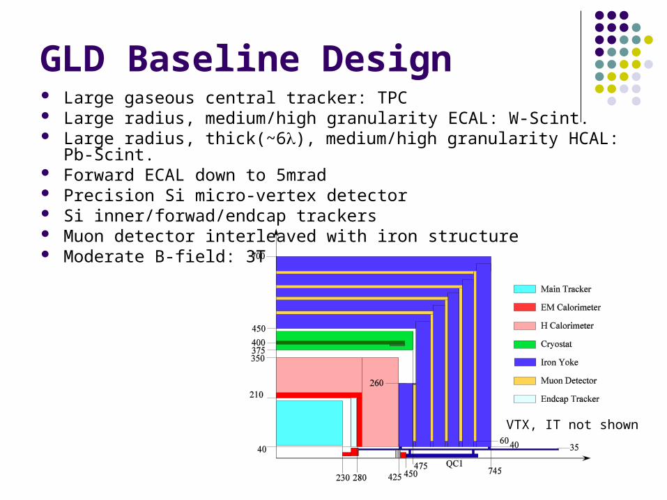
GLD Baseline Design Large gaseous central tracker: TPC Large radius, medium/high granularity ECAL: W-Scint. Large radius, thick(~6), medium/high granularity HCAL: Pb-Scint. Forward ECAL down to 5mrad Precision Si micro-vertex detector Si inner/forwad/endcap trackers Muon detector interleaved with iron structure Moderate B-field: 3T
VTX, IT not shown

Vertex detector Role: Heavy flavor tagging
Important for many physics analyses: e.g. Higgs branching ratio measurement
Efficient flavor tagging requires excellent impact parameter resolution:
Goal: = 5 10/(psin3/2) m Sensor technologies
Must cope with high background rate Readout 20 times/ train, or Fine pixel (20 times more pixels)
option : readout once/ train

Vertex detector Main design consideration
Inner radius: Beam pipe radius: Dense core of
pair background should not hit the beam pipe B-dependence not so large: ~B-1/2
Large machine-option dependence Back scattered e+- from BCAL (L
ow-Z mask in front of BCAL should cover down to R<RVTX )
Layer thickness: As thin as possible to minimize m
ultiple scattering I.P. resolution / tracking efficienc
y for low p particles GLD baseline design
Fine pixel CCD Inner/outer radius: 20(?) – 50 mm Angle coverage: |cos|<0.9/0.95

Si trackers
Role: Cover large gap between TPC and VTX Si Inner Tracker (IT) TPC and endcap ECAL Si Endcap Tracker (ET)
to get better Track finding efficiency Momentum resolution Track-cluster maching in ECAL (PFA)
Design optimization Number of layers and their position Wafer thickness Strip or pixel? for the very forward region

Main tracker: TPC
Performance goal: pt/pt2 = 5x10⁻⁵ /GeV combined with IT and VTX
Advantages of TPC Large number of 3D sampling
Good pattern recognition Identification of non-pointing tracks
(V0 or kink particles) : e.g. GMSB SUSY
Good 2-hit resolution Minimal material Particle ID using dE/dx
G~~
e+ e- ZH X

TPC
Baseline design Inner radius: 40 cm Outer radius: 200 cm Half length: 230 cm Readout: ~200 radial rings
Open questions Readout: GEM or Micromegas? Material budget of inner/outer wall and end plate Background hit rate and its effect on spatial resolution due t
o positive ion buildup (occupancy is OK even with 105 hits in 50s)

Tracking performance
GLD conceptual design achieves the goal of pt/pt2 = 5x10⁻⁵ /GeV
pt/p
t2 (G
eV
-1)
By A.Yamaguchi(Tsukuba)
Monte Carlo

Calorimeter
Performance requirement Goal for jet energy resolution is E/E = 30%/E1/2
Then, what is the requirement for CAL? The answer is not simple. We need a lot of simula
tion study of PFA

ECAL Current baseline design
33 layers of [3mm W + 2mm Scinti. + 1mm gap (readout elec.)]
~28 X0, ~1 , RM~18mm Wavelength shifter fiber + MPC
(Multi-pixel Photon Counter, =SiPM) readout
4cmx4cm tile and 1cm-wide strips Granularity has to be optimize
d by PFA simulation study Calibration method for small s
egments is worrisome Very fine segmentation with Si f
or first few X0 is also discussed
MPC 400pixels
MPC 100pixels (10x10pixels)
~85um
~100um

HCAL Current baseline design
50 layers of [20mm Pb + 5mm Scinti. + 1mm gap (readout elec.)]: (“Hardware compensation” configuration)
~6 Wavelength shifter fiber + MPC
(Multi-pixel Photon Counter, =SiPM) readout
20cmx20cm tile and 1cm-wide strips Granularity has to be optimized
by PFA simulation study Digital HCAL is also considered a
s an option Open questions
Global shape: Octagon, dodecagon, or hexadecagon?
How to extract cables?
Hamamatsu MPC (H100) spectrumUp to ~40 photon peak! is observed

FCAL/BCAL
BCAL Locates just in front of final Q Coverage: down to ~5mrad W/Si or W/Diamond (No detailed
design yet)
FCAL Z~2.3m Also work as a mask protecting
TPC from back-scattered photon from BCAL
W/Si (No detailed design yet)

Muon detector / Magnet Muon detector
Possible technology: Scintillator strip array read out with wavelength shifter fiber + MPC
Number of layers, detector segmentation, etc. have to be studied
Magnet 8 m 3T superconducting sol
enoid Stored energy: 1.6 GJ Excellent field uniformity for
TPC:
mmdzBz
Brz2max
0

Cost Issues Major cost consumers: Solenoid, HCAL, ECAL Solenoid
Cost~0.523xE(MJ)0.662 [PDG]~70M$ HCAL
Volume~230m3, Area (all layers)~87Mcm2
Cost~87M x cost/cm2
ECAL Volume~22m3, Area (all layers)~37Mcm2
Cost~37M x cost/cm2
Requirement for granularity from physics determines the CAL design and the cost: Simulation study is urgent

Summary GLD design study is being carried out both from accelerator point
of view and from physics point of view ILC detectors should be optimized for PFA performance, and
large detectors are suitable for that In GLD concept study, we investigate detector parameter space
with large detector size and slightly lower B and CAL granularity Baseline design of GLD has been shown, but current GLD
baseline design is not really optimized. More simulation study, sub-detector R&D effort, and new ideas are necessary The purpose of this workshop