the management of steam locomotive - athraathra.asn.au/library/uk_the_management_of_steam... ·...
TRANSCRIPT
THE MANAGEMENT OF STEAM LOCOMOTIVE BOILERS
Railway Safety Publication 6
1

First published by the Health and Safety Executive, 2005
Second edition published by the Office of Rail Regulation, 2007
This guidance is issued by the Office of Rail Regulation. Following the guidance is not compulsory and you are free to take other action. But if you do follow the guidance you will normally be doing enough to comply with the law. Railway inspectors seek to secure compliance with the law and may refer to this guidance as illustrating good practice.
2
Contents
Foreword 5
Introduction 6
Risks to people 7
Principal legislation 8
Management of locomotive boilers 11
Responsible person(s) 11
Competent person(s) 11
Locomotives not owned by a railway 11
Fittings and attachments 12
Boiler examination and testing by the competent person 13
Choice of competent person 13
Frequency of examination 14
Thorough examination 14
Examination reports 15
Boiler inspection and testing by the railway 15
Operation 17
Means of escape in an emergency 17
Use of the boiler 17
Repairs and maintenance 18
Records 18
Maintenance policy 18
Materials used for maintenance and repair 18
Boiler feed water 18
Boiler blowdown 19
Boiler washout 19
Washout plugs and mudhole doors 20
Boiler tubes 20
Superheater elements 20
Firebox repairs 21
Rivets and set screws 21
Patches and inserts 21
Welding repairs 21
3
Steam pipes and joints 21
Boiler lay-up procedure 22
Hydraulic pressure testing 22
Safety valves 22
Fusible plugs 22
Asbestos thermal insulation 23
Train heating boilers 23
Oil-fired boilers and conversion from coal to oil fuel 23
Statutory requirements 25
Appendices 26
1: Suggested declaration in respect of the boiler of a locomotive on loan 26
2: Typical boiler inspection, examination and maintenance programme 27
3: Typical locomotive boiler log sheet 29
4: Report of an examination by a competent person of a boiler when cold 31
5: Report of an examination by a competent person of a boiler under normal steam pressure 32
6: Recommended steaming times for replacement of fusible plugs 33
7: Table of working and test pressures 34
8: Materials for locomotive boilers 35
References and further reading 40
References 40
Further reading 41
Further information 42
4
Foreword
This document has evolved from a previous HSE publication, Locomotive boilers HSG29, first published in 1986. HM Railway Inspectorate is indebted to the many people who have contributed to its development and given many constructive comments, in particular:
Allan Garraway, Heritage Railway Association
Alun Rees, Severn Valley Railway and Heritage Railway Association
Graham Beddow, Severn Valley Railway
Mike Heintzman, Severn Valley Railway
Robert Meanley, Birmingham Railway Museum
Glyn Hawkins, HSE Specialist on pressure systems
Major John Poyntz, HM Railway Inspectorate
Steve Turner, HM Railway Inspectorate
David Keay, HM Railway Inspectorate
It is hoped that operators and owners of steam locomotives will find this guidance helpful.
5

Introduction
1 This document is intended to give guidance and advice to those involved in the management, examination, repair, maintenance and operation of railway locomotive boilers. In drafting it, the special needs of minor railways have been taken into account. The document will also be relevant to owners and operators of other rail vehicles that have a steam boiler, such as railway steam cranes, Sentinel locomotives and railcars, although these are not of a conventional railway locomotive type. This document does not set out mandatory standards but it does set out examples of good practice acceptable to HM Railway Inspectorate to provide an adequate level of safety.
2 A considerable amount of knowledge relating to steam locomotive boilers had been accrued by British Railways prior to the end of commercial steam locomotive operation on the network. Procedures for the maintenance and repair of locomotives had been well established, and it is recommended that former British Railways locomotive maintenance and workshop practices are used and are considered to be best practice. Furthermore, private owners such as the National Coal Board and the Central Electricity Generating Board developed maintenance and workshop practices specifically for industrial-type locomotives. The implications of deviations from former methods or materials should be fully assessed before adoption.
Note: There are a number of historic publications that may be obtained from the Heritage Railway Association relating to the care and maintenance of locomotive boilers, in particular, the document formerly published by the British Railways Chief Mechanical and Electrical Engineer Instructions Relative to Boilers 19591 (known colloquially as ‘the Red book’).
3 All references to pressure in this document relate to pressure above atmospheric pressure. The units of pressure used in the text are ‘bar’ and ‘pounds per square inch’, both of which are used and understood by those working with locomotive boilers. A list of equivalent values for 1 bar expressed in other units is given below:
1 bar = 14.5038 lb/in2 (pounds per square inch)
29.53 in of Hg (inches of mercury) 10
5 Pa (Pascals)
105 N/m
2 (Newtons per square meter)
10197.2kgf/m2 (kilogramme force per square meter)
6
Risks to people 4 A defect in a locomotive boiler (or its fittings) that allows an escape of steam can give rise to severe scalding or even death of people on the footplate. The principal dangers to be guarded against are:
(a) collapse of the firebox due to broken stays or low water level;
(b) collapse of fire tubes or superheater flues;
(c) bursting of steam pipes in the cab through work hardening;
(d) blowout of washout plugs, fusible plugs, mudhole door joints and gauge glasses;
(e) reversal of draught (blowback) resulting from the failure of steam pipes, any loss of vacuum in the smoke box, or loose or detached fittings in the smoke box which may interrupt the draught;
(f) failure of superheater elements;
(g) corrosion of the boiler or firebox leading to the risk of cracking.
5 A factor to be borne in mind when considering these dangers is that many preserved locomotives are very old and some may have lain in a scrap yard condition for a number of years without any protection against internal and external corrosion.
6 Saturated or superheated steam, hot coals and flue gas are likely to be discharged into the cab if some of the events described in paragraph 4 occur. As an example of steam temperatures, saturated steam at a gauge pressure of 13 bar g (190 psi) has a temperature of 195°C. Scalding from contact with the steam will be almost instantaneous. In most cases it will be impossible to stop the escape of steam, so the only way to avoid extensive burns will be to flee from the footplate, which carries other risks if the locomotive is in motion.
7
Principal legislation
7 Steam boilers are subject to the requirements of the Pressure Systems Safety Regulations 2000
2,3 which, among other things, requires a periodic examination by a competent person of:
(a) all protective devices;
(b) every pressure vessel in which a defect may give rise to danger; and
(c) those parts of the pipework in which a defect may give rise to danger.
8 The Health and Safety at Work etc Act 19744 (HSW Act) imposes general duties which are
relevant to the safe use of railway locomotive boilers:
(a) Sections 2 and 4 impose a general duty on employers or people who have control of premises to ensure that plant and equipment are maintained in a safe condition, so far as is reasonably practicable;
(b) Section 3 requires that undertakings be conducted, so far as is reasonably practicable, in such a manner as not to endanger people who are not employees;
(c) Section 6 imposes duties on suppliers of articles for use at work. New items of pressure equipment, such as boiler barrels, are subject to the Pressure Equipment Regulations 1999.
5
8
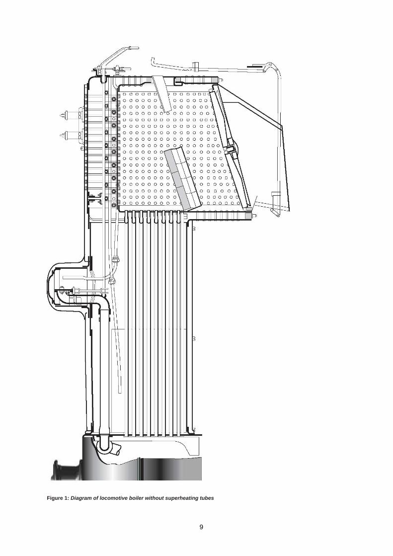
Figure 1: Diagram of locomotive boiler without superheating tubes
9
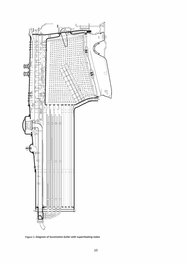
Figure 2: Diagram of locomotive boiler with superheating tubes
10
Management of locomotive boilers Responsible person(s)
9 The safe operation of steam boilers depends upon the correct management approach. The examination, testing, repair and maintenance of boilers should be carried out to an adequate standard, and this in turn requires the choice of suitable people, both to carry out and to supervise these functions. Records should be kept of steaming time, examinations, details of repairs and the extent of maintenance carried out. To ensure that all this is successfully achieved, it is strongly recommended that each railway organisation appoints one person to take responsibility for co-ordinating the work necessary to ensure the safety of the boilers on their railway; large organisations might appoint more than one person, each with clearly defined areas of responsibility. Each person so appointed will be referred to in this publication as the ‘responsible person’.
10 A responsible person should be formally appointed by the railway organisation. The responsible person should be made aware of their responsibilities and duties, and be given sufficient independent authority to prohibit the raising of steam in any boiler if in doubt about its safety.
11 It would be usual to appoint an engineer as the responsible person, and ideally that person would be a chartered mechanical engineer with knowledge of boilers. However, regardless of whether the responsible person is an expert on boilers, he should ensure, by seeking expert advice if necessary, that those who carry out the inspections, examinations, repairs, maintenance and operation of locomotive boilers are competent in the duties they have to perform that relate to boiler safety. The publication Railway Safety Publication 1: Developing and Maintaining Staff Competence
6 contains advice for those
responsible for managing, assessing and maintaining competence.
Competent person(s)
12 Guidance is given in paragraphs 21 and 22 on the selection of a further person or organisation, referred to here as the ‘competent person’, who will carry out the periodical examination of boilers.
13 A competent person should have practical and theoretical knowledge and actual experience and understanding of relevant plant, fittings, type of locomotive and access, where necessary, to specialist services. They should possess a proper degree of independence from those responsible for the operating function, and proper standards of professional probity so as to enable them properly to carry out examinations and such assessments as are necessary.
14 The advice of the competent person might also be obtained on the maintenance and operation of the boiler. Similarly, their guidance might be sought regarding repairs.
Locomotives not owned by a railway
15 Some railways operate, either permanently or occasionally, locomotives owned by one or more independent people or groups, and when entering into any hiring, leasing or loan of a locomotive, the arrangements for its maintenance should be considered. Ideally, the railway should be responsible for inspection, examination, repair, routine maintenance and operation of the boilers of the locomotives that normally use its tracks. However, even where the owners of the locomotives carry out some of these functions, the responsible person of the railway should still have responsibility for ensuring boiler safety.
16 The user of the locomotive, not the owner, is responsible for arranging examinations and maintenance. It will be necessary for the responsible person to maintain close liaison with the owner and to be satisfied with both the choice of competent person, and with the competence of the person(s) carrying out routine inspections, repairs and maintenance of the boiler, and with the standards of workmanship, maintenance and operation. In addition, the responsible person should obtain written assurance from the owner(s) that the boiler has been properly maintained and is in a safe condition.
17 The responsible person should check that the latest report of examination and tests showed the boiler to be in satisfactory condition. It is recommended that such examination and tests were carried out within the previous 14 months or such lesser period as may have been stipulated in the report (see paragraph 18). A suggested form for use in these circumstances is given in Appendix 1. When the responsible person is not able to assure himself on these matters he should arrange to have the boiler examined and tested by a competent person on his behalf, before it is used on the railway.
11
18 Where a locomotive is not owned by the railway on which it is to be operated, the logbook and examination reports (or copies thereof) should be handed over to the responsible person of the railway where it is being operated before it is put into use. Not only will these documents be useful for the user railway, but they will then be readily available to those authorised to see them in connection with an inspection of the railway.
Fittings and attachments
19 For safe operation of a locomotive boiler, the following fittings and attachments should be included:
(a) two safety valves, fitted directly onto the boiler. There should be no means of isolating the safety valve(s) from the steam boiler;
(b) a calibrated steam pressure gauge independently connected to the steam space through an independent shut-off valve, marked in a distinctive manner to indicate the maximum permissible working pressure, and visible to driver and fireman;
(c) at least two methods of determining boiler water level. Preferably both of these will be the transparent type of gauge, but a set of two or three test cocks is acceptable in place of a second transparent gauge. Unless the transparent gauge is of the Klinger reflex type, it must be provided with a transparent safety guard to protect people on the footplate in event of gauge-glass breakage. The fitting of a thin backing plate to the transparent safety guard, painted in alternate black and white diagonal stripes, greatly assists the observation of water level in the gauge glass and is recommended. It is also recommended that water-gauge fittings incorporate valves to restrict the flow of steam and water in the event of breakage of the gauge glass. Where necessary, for operation in poor visibility and hours of darkness, the water gauges should be illuminated;
(d) at least one fusible plug in the firebox crown;
(e) an easily visible and permanent means of identification and the maximum permissible working pressure for the boiler should be marked;
(f) there should be two independent means of supplying feed water to the boiler while it is under steam pressure;
(g) a device for determining the water content of the locomotive water tanks or tender water tank. This can be a gauge, test cocks or a dipstick and should be visible from the locomotive footplate and where applicable, operable from it.
12
20 The design and construction features of the boiler should not be altered from the original design without the written consent of the competent person. Examples may include the replacement of a copper firebox with one of steel construction, using a welded boiler in place of a riveted boiler, the fitting of additional pads or patches or amendment to the design of stays.
Boiler examination and testing by the competent person
Choice of competent person
21 One of the prerequisites of safe boiler operation is the thorough examination carried out periodically by a competent person (see paragraph 12). This examination is required by the Pressure Systems Safety Regulations 2000,
2 and is not to be confused with the more frequent inspection usually
carried out by the railway’s own staff at the time of boiler washout. The words ‘inspection’, ‘competent person’ and ‘examination’ are used throughout this document in the context given in this paragraph.
13
22 The competent person may have a role to play as a general adviser to the railway on the repair, maintenance and use of locomotive boilers, in addition to his prime function of carrying out the examination. The choice of competent person is therefore an important one. Unfortunately it is not possible to stipulate that a person with certain qualifications would necessarily be suitable as a competent person; in practice, knowledge is widened with experience and through the information accumulated. Owing to the problems associated with the construction of a locomotive boiler, which a competent person is unlikely to meet in other types of boiler, he should have had previous experience of locomotive-type boilers. The competent person should normally be a suitably qualified and experienced engineer. The user of the locomotive must select the competent person. It is usual for an engineering surveyor to act on behalf of an associated insurance company. The choice of insurance company may well be dictated by its experience in locomotive boiler examination.
23 Before a boiler is operated, the user/owner must ensure that a written scheme of examination has been prepared.
2 The competent person should draw up the written scheme of examination, or if
drawn up by someone other than the competent person, the competent person must certify it as suitable.
Frequency of examination
24 The examination by a competent person should be carried out in the manner specified in paragraphs 26 to 29 and detailed in the written scheme of examination, that is:
(a) during the course of periodical overhaul;
(b) before a new boiler is steamed for the first time;
(c) at a frequency no greater than the time specified by the competent person in his scheme of examination;
(d) after failure of a fusible plug for any reason.
25 Where any repair has been carried out that, in the opinion of the competent person, may affect the safe working of the boiler, it should be examined by the competent person in such a manner as will enable him to satisfy himself that the repair has been properly carried out.
26 When reporting on any examination, the competent person should be satisfied that the boiler could continue to be steamed safely under normal operating conditions and pressure until the next specified inspection or such lesser period as may be specified in the report, giving due regard to the expected use of the boiler.
Thorough examination
27 The thorough examination consists of an examination by the competent person in accordance with the written scheme when the boiler is cold (which may include a hydraulic pressure test, should the condition of the boiler be cause for concern) and an examination under steam pressure. The latter should be completed as soon as possible after the examination when cold.
28 The examination when cold is essentially a visual examination, both internal and external, of those parts of the boiler and firebox that are accessible, including fittings, steam pipes in the smokebox and on the footplate, superheater elements (where applicable) and supplemented where appropriate by testing the thickness of material and a hydraulic pressure test. The extent of each examination is at the discretion of the competent person. To avoid delay in completing it and, at the same time, to limit preparation to a minimum, the railway should first agree with the competent person on the extent of the preparations required. This would not preclude the competent person from calling for further dismantling after the examination had commenced. However, the least preparation that would be needed would include:
(a) thorough cleaning and descaling of the water side of the boiler;
(b) thorough cleaning of the smokebox and firebox, probably including removal of firebars if practicable;
(c) removal of all mudhole doors and washout plugs;
(d) stripping and cleaning of water gauge frames;
14
(e) removal of the fusible plug(s).
29 Notwithstanding the stipulations in the preceding paragraph, no part of the boiler should remain completely unexamined for longer than the time determined by the competent person, best practice would indicate a maximum time period of ten years. In the intervening period, the competent person may call for the removal of ‘sample’ tubes or other such dismantling necessary for reasons of accessibility, e.g. where the firebox is contained within the frames and is therefore not visible. Preparatory work for this examination may involve:
(a) removal of the boiler fittings, superheater elements and all tubes;
(b) stripping the cladding and insulation from the boiler;
(c) where necessary, lifting the boiler from the locomotive frames;
(d) examination of all engineers’ studs mounted on the boiler.
30 For the examination under steam pressure, a pressure just below the maximum permissible working pressure should be maintained for not less than one hour without signs of leakage or other defects. If the examination discloses significant leakage or other material defect, the pressure should be completely relieved before the defect is rectified. The pressure should be re-applied when the defect has been made good. The boiler should be fitted with a certified safety valve. The setting of the safety valve(s) should be checked against either a master pressure gauge or the one normally used with the boiler if its accuracy has been verified against a master pressure gauge.
31 On completion of the examination under steam pressure, the boiler should be drained and the firebox stays tested either by traditional hammer testing, or by any other suitable non-destructive test not involving the excessive grinding of rivet or stay ends if:
(a) the boiler is new or fresh from major repair;
(b) repairs have been carried out necessitating a full hydraulic pressure test;
(c) a boiler is brought back into use after having been laid up for a period in excess of one year.
Examination reports
32 A suggested format for use when reporting on the examination of a boiler when cold is given in Appendix 4, and in Appendix 5, there is a suggested format for reporting on an examination under steam pressure.
33 The reports should be sent to the responsible person as soon as possible, and in any case within 28 days of the examination. If a report calls for any repairs to a safety critical component, a copy should be sent as soon as practicable and in any case within 28 days to HM Railway Inspectorate or, in the case of a locomotive operating on premises subject to the Mines and Quarries Act 1954, to the local office of the HSE. Moreover, whenever the competent person calls for repairs affecting safe working, he should, if practicable, notify the responsible person or other appropriate railway official of this fact at the time of the examination.
34 A series of examination reports forms a valuable history of a boiler and should be kept for its lifetime. In any case, they should be kept from one main overhaul of the boiler to the next. The previous report should always be made available to the competent person during a periodical thorough examination.
Boiler inspection and testing by the railway
35 In addition to the examination by a competent person previously described, boilers should be inspected as follows by a person appointed by the responsible person:
(a) under steam pressure prior to washout, to look for signs of leakage at tubes, stays, seams, fusible plugs etc. Reference should be made to driver’s report cards for additional information;
15
(b) after washout, before plugs and doors are replaced, and again after plugs, doors and any other fittings are replaced. The boiler should then be inspected in steam to ensure the integrity of all plugs, doors and fittings which may have been repaired;
(c) before bringing into use a boiler that has been laid up for a period during the currency of the certificate of thorough examination, it is necessary to look for evidence of deterioration resulting from the effects of corrosion.
36 These inspections would normally be carried out by the railway’s own staff, if sufficiently experienced in these matters, or by an expert retained by them for the purpose. Their object is to ensure that the boiler remains fit for continued service until either it is inspected again or the competent person carries out the next periodical examination. The competent person should be advised if signs of significant deterioration are seen.
37 The inspections should include the following:
(a) water spaces, to ensure that all scale, dirt and sludge were removed during the washout, paying particular attention to the spaces around the base of the firebox and to the firebox crown and the condition of visible stays for necking, corrosion, pitting, wastage or fracture, checking boiler barrel bottoms and tube nest at tube plate for scale build up;
(b) the hammer testing of stays;
(c) the firebox, for bulging that may indicate the presence of broken stays, and for wasted stay heads, rivet heads on the fire side and water side and stay nuts, and for fractures from rivet, tube or stay holes, or along flange radii;
(d) the condition of the element in fusible plugs and the conditions of the threads;
(e) the inside and outside of the visible parts of both small and large tubes for signs of pitting, cracking, bulging or wastage;
(f) the water side of the boiler shell at foundation ring level for signs of grooving, and firebox wrapper, doorplate, throatplate for signs of cracking or fracture along lines of stays or washout plugs;
(g) the smokebox generally for corrosion and in particular the bottom of the smokebox tube plate for corrosion and wastage due to the accumulation of damp ash;
(h) water gauge fittings and test cocks to ensure that all passages are clear and unobstructed; Note: It should be possible to insert a rod no more than 1.6 mm (1/16 in) smaller than the openings (or a square-section rod with a diagonal of the same dimension). Care should be taken when inserting the rods not to damage any curved pipes sometimes fitted inside the boiler behind the upper gauge fitting. In the case of fittings with coupled cocks it should be possible to pass the rod through both cocks without moving the handle when the coupling rod is fitted and the cocks are in the open position;
(i) gauge glasses for signs of pitting, wastage of ends, flaws or streaks - if these are found, the glass should be replaced;
(j) the alignment of any refitted gauge frame fittings. This should be checked by passing a closely fitting rod through them - misalignment is a prime cause of gauge glass breakage;
(m) the condition of washout plugs, washout holes, mudholes and mudhole doors, with particular attention to the fit of mudhole doors.
(n) steam pipes and superheater elements (where fitted) in the smokebox;
(o) fittings in the smokebox for security, including the integrity of the blast pipe. Any obstruction in the path of the exhaust steam from the blast pipe could cause a serious blowback through the firebox into the driving cab;
(p) operation of the regulator, to check ease of operation.
16
Operation Means of escape in an emergency
38 Since the risk of an escape of steam or boiling water into the cab cannot be entirely eliminated, those on the footplate should be able to escape quickly in the event of trouble. Unless the locomotive is standing at a platform, speedy exit from the footplate is not easy. The opening at the side of the footplate is usually narrow and there may be a pair of doors to be opened.
39 At all times when the locomotive is in motion with the regulator shut, the blower valve should always be open. To minimise the risk of blowback, the blower valve should also be opened when passing under low bridges or through tunnels, and the firebox door should be kept closed.
40 For these reasons, and except in the circumstances of sub-paragraphs (a) and (b) below, it is recommended that the number of people travelling on the footplate of a steam locomotive should be kept to a minimum, and should not exceed four unless either:
(a) special arrangements are made to protect people from an escape of steam, such as provision of a suitable screen, or
(b) the locomotive is standing at a platform, where exit from the footplate is relatively easy and the boiler pressure is maintained at substantially less than its maximum permitted working pressure.
Use of the boiler
41 Except when conducting a hydraulic test, under no circumstances should the maximum permissible working pressure specified on the boiler be exceeded.
42 Maintaining correct water level in the boiler is essential to safe operation and this in turn depends on the gauge glass registering the correct level. Several catastrophic accidents have occurred due to faulty gauges. The gauge glass, cocks and trial taps should be blown through when taking over a locomotive, to ensure that no scale obstructs the passages between the boiler and the gauge glass.
43 For locomotives with coupled gauge-glass cocks, a periodic examination under steam should be conducted with the gauge cocks uncoupled and individually tested. Locomotives having only one gauge glass are fitted with try cocks that should also be tested at each steaming. When two separate gauge glasses are fitted, check that both gauges register the same level of water.
44 It should be noted that on many locomotives a fusible plug is a significant distance from the gauge glass, and with the water just showing at the bottom of the glass, the fusible plug may only be covered by about 25 mm of water. Ascending a gradient with such a level of water will result in the front plug having no water cover and after passing over a summit, the firebox crown may also be uncovered. This situation may also occur under prolonged heavy braking with reasonable water levels. The crown sheet of the firebox may also be uncovered when the locomotive is standing on a superelevated curve. Consideration should always be given to the topography of the line upon which a locomotive is to be used, especially in the case of locomotives moving from one railway to another.
45 Boiler temperature should be raised and lowered gradually so as to minimise stresses due to rapid and uneven expansion or contraction. This is particularly important if boilers are oil-fired. For coal-fired boilers, the practice of dropping the fire and filling the boiler with cold water at the end of the service period should be discouraged.
17

Repairs and maintenance
Records
46 A record should be kept of all boiler steaming days, washouts, inspections, reported defects, repairs and maintenance work carried out. There should be a separate record for each boiler so that there will be no doubt when any boiler is next due for maintenance etc. Some simple record forms are suggested in Appendix 3, but the content of the maintenance policy described in paragraph 47 will determine the overall records that need to be kept.
Maintenance policy
47 A maintenance policy that lays down frequencies of boiler washout and inspection, and of all other maintenance work on the boiler and its fittings, should be adopted. The responsible person, who (if necessary) should take suitable advice and inform the competent person, should approve the policy. A typical maintenance programme is given in Appendix 2 as a guide, but it is important that each railway determines frequency of washout and related maintenance and inspection on the basis of the nature of the boiler feed water, its treatment and locomotive usage. If in any doubt about washout frequency, the railway should seek advice from the competent person. Some aspects of maintenance are discussed more fully later.
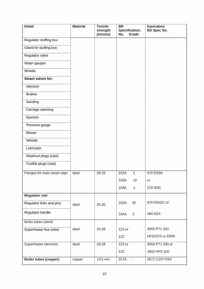
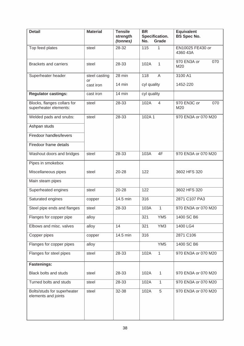
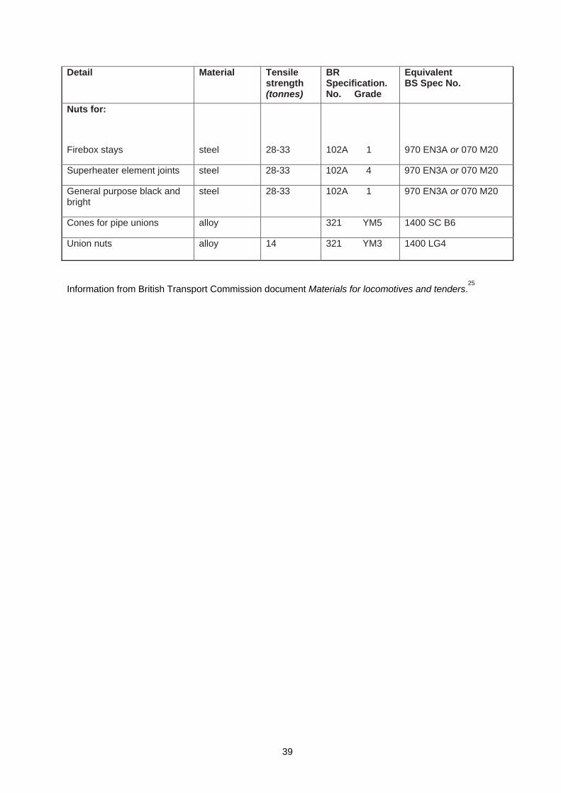
Materials used for maintenance and repair
48 All boiler components should be considered to be safety critical, and as such, replacement items should be manufactured from materials of the highest quality, obtained from sources having quality control systems that will ensure the traceability of any material they may supply. Complete records should be kept for all material orders together with test certificates and certificates of conformity for materials supplied to such orders. The responsible person should ensure that all materials used conform to the materials originally specified for any boiler components that are to be replaced. A schedule of materials for locomotive boilers based upon British Transport Commission specifications is given in Appendix 8. While this provides generic guidance, the original material specifications and method of repair should be obtained where possible. Where significant repairs are needed that will materially affect the original design of a boiler, conformity with the Pressure Equipment Regulations 1999
5 will be required.
Boiler feed water
49 All water contains impurities, which may vary considerably according to the location of their source. These impurities may make the water alkaline or acidic, and dependant on mineral content, will form scale or sludge with widely varying characteristics:
(a) excessive acidity will cause problems with corrosion of tubes and steel plates. An early indication of acidity is the disengagement of existing scale from plates, stays and tubes;
(b) excessive alkalinity will also cause problems, particularly when even minute leakage paths exist at riveted joints;
(c) some waters will deposit heavy quantities of hard scale on heating surfaces, particularly fireboxes and tubes, which will become burned, thinned and mechanically weakened due to the insulating properties of the scale. Excessive scale deposits, particularly around the firebox tubeplate, foundation ring and firehole will impede water circulation, leading to accelerated scale build up, burning and corrosion.
50 To minimise such problems, the responsible person should ensure that the water source used for boiler feed is analysed regularly, as is found to be appropriate following experience of analysis, to establish measures to suitably treat the feed water as necessary to bring it to an acceptable standard for use in a boiler.
51 All boiler contents should be checked periodically between washouts to ensure that dissolved and suspended solids, alkalinity/acidity and concentrations of feed treatment chemicals are kept to levels recommended in British Standard BS 2486: 1978 Recommendation for treatment of water for land boilers.
7
18
52 The objectives of feed water treatment are:
(a) to keep the internal evaporative surfaces of the boiler clean and free from scale;
(b) to prevent corrosion by the control of acidity and reduction of dissolved oxygen;
(c) to prevent the solidification of scale-forming impurities in the water and to assist removal of residue at blowdown and washout periods;
(d) to assist in the prevention of water carry-over in the steam due to high levels of dissolved solids in the water;
(e) the selection, application and control of water treatment should be consistent with these aims.
53 In view of its importance in respect to the rate of boiler deterioration and to the length of boiler washout periods, all water treatment should be authorised and managed by the responsible person after discussion and agreement with the competent person. Feed water treatment regimes will vary considerably dependent on the wide variations in the quality of raw feed water available from area to area, and sometimes even in the same area due to water companies mixing water supplies due to seasonal demand. It is important to recognise that badly specified and/or poorly executed feed water treatment can cause considerable deterioration and damage to boilers. It is therefore essential that all programmes of feed water treatment are planned and managed by individuals who possess an acceptable level of expertise in this subject. It is also essential that considerable diligence is applied to the maintenance and control of feed water regimes once they are established. Ideally one person should undertake the addition of chemicals and maintenance of records. Advice on feed water treatment may be obtained from the Heritage Railway Association or from a number of specialists in this field.
54 Where considerable quantities of boiler feed water are being consumed, consideration should be given to the use of automatic dosing apparatus and even to specialist feed treatment equipment.
55 The feed water treatment selected will dictate special requirements such as blowdown and washout periods. Certain systems which precipitate impurities will require blowdown to remove sediment and mud from the foundation ring and will also determine the frequency at which the boiler needs to be washed out.
Boiler blowdown
56 Certain precautions are necessary when manually blowing down, in addition to the obvious one of ensuring that no one is scalded by the escaping water and steam. Water level should be maintained and a good fire kept in the firebox to maintain sufficient steam pressure to work the injectors (the operation of which should always be tested prior to blowing down). When the locomotive is stationary, a pipe should be firmly connected to the blowdown cock and its open end directed away from the front of the engine to avoid blowing up dirt and grit into the moving parts. Consideration should be given to the generated noise levels and the restraint of the pipe.
Boiler washout
57 The interval between boiler washouts should be determined by the responsible person, as it depends on the purity of the feed water and the extent of steaming and of blowing down.
58 A lot of boiler trouble can be traced to over-rapid cooling preparatory to washing out or water changing. It should always be arranged that boiler draining is only begun after the boiler, when full of water, has cooled down to a temperature of about 20°C above ambient. It should be recognised that a boiler can take several days to cool naturally.
59 The most important factor in boiler washing where hard scale is to be removed is to maintain an adequate pressure and rate of flow of water which, if less than 4 bar (60 lb/in
2), should be boosted.
During the washing out of the boiler shell and firebox water spaces, vigorous rodding is necessary to remove scale. Brass or copper wire rods should be used to avoid damage to threads of washout plugholes and internal parts. For the reasons given in paragraph 46, it is most important that descaling be done thoroughly. Acid cleaning for removal of scale is not recommended and should not be carried out without the agreement of the competent person.
19
Note: The smallest booster pump that can reasonably be used is one delivering 3 litres/sec (2500 gal/h) against a pressure of approximately 4.8 bar (70 lb/in2) that is just sufficient to supply one 19 mm (3/4in) nozzle, straight and offset nozzles are used.
Washout plugs and mudhole doors
60 Washout plugs and mudhole doors should not be removed until the boiler is completely free of steam pressure, which can be determined by opening injectors or other open-ended fittings. The steam pressure gauge should not be relied upon for this purpose. On removal, washout plugs and mudhole doors should be identified with the holes from which they are taken to ensure that they are returned to the same positions on refitting.
61 All plugs should be carefully examined for any cracking occurring around the square head and for the condition of the thread. The threads of plugs should be thoroughly cleaned before replacing and, when fitted, should engage all threads in the plate. Owing to the taper and fine pitch of the threads, some care is necessary when replacing washout plugs (and fusible plugs where applicable) to avoid crossed threads. It is important that the plugs, when fitted, should not bottom on any internal parts. When re-tapping plug holes or renewing plugs, care should be taken to ensure the tap and plug has the correct taper and pitch of thread. All plugs should be manufactured from Leaded Gunmetal LG4 material to British Standard BS 1400: 1985
8 and BS EN 1982: 1999 Copper and copper alloys. Ingots and castings.
9
It is important to note that not all locomotives have the same taper or pitch of thread, and several serious accidents have been caused by fitting incorrect plugs. Washout plugs should never be touched when the boiler is in steam, a fatal accident may result from any attempt to tighten washout plugs when under steam pressure.
62 Mudhole doors, bridges, studs and nuts should be carefully examined after each removal in view of the corrosion that takes place. All mudhole door joints should be of a suitable pattern and joint materials such as cast lead may be used for most classes of locomotive. Both asbestos and lead joints require robust procedures to avoid the health hazards presented by these materials and control measures must be implemented to adequately control the exposure of people to lead and asbestos
10-14 (see also
paragraphs 90-94). Suitable and sufficient arrangements must be made for the disposal of such materials.
10-14 It is essential that the fit of the door spigot in its relevant hole provides the minimum
practicable gap to prevent extrusion of the joint through the gap. Settlement of door joints will occur as pressure is raised and the mudhole door nuts should be progressively tightened to take up this settlement.
Note: With suitable control measures it is possible to recycle lead joints, whereas asbestos joints must be disposed of after single use.
Boiler tubes
63 No boiler tubes should be replaced without prior approval of the responsible person. Suitable tools should be used for the work and it is strongly recommended that only five or six-roller expanders are used for expanding the tube ends, as their use will generally improve the life expectancy of the tube plates. All tubes obtained as replacements should be to British Standard specification BS EN 10216-1: 2002
15 and BS EN 10217-1: 2002,
16 or an equivalent standard. They may be either solid drawn or electric
resistance welded. The responsible person should retain a copy of the relevant material and test certificates for such tubes.
64 When tube plate holes became oversized due to repeated expansion of tubes, it was custom and practice to fit annealed copper liners to bring the tube hole back to original size to permit the fitting of standard diameter tubes without the risk of over-expansion. Where it is considered a possibility to fit liners, it should be established that there is sufficient material to support the tubes. This work should not be undertaken without the prior consent of the competent person. In no circumstances should the thickness of a liner exceed 3 mm (10 SWG). The use of ferrules to reinforce tubes should not be permitted other than where originally fitted for the protection of non-ferrous tubes.
Superheater elements
65 When new superheater elements have had ends fitted, or tubes have been repaired by welding (or brazing in the case of copper ended tubes), they should be tested in the manner prescribed by the
20
competent person. This should be by non-destructive examination, preferably radiography and if necessary, the application of a hydraulic test before they are replaced in the boiler.
66 All repairs to and replacement of superheater flue tubes, whether welded, screwed or copper ended, should be carried out under the supervision of the responsible person or a repairer nominated by him. All tubes should be solid drawn to the appropriate British Standard or an equivalent standard. Where new screwed ends are to be fitted to tubes, these portions should also be to the appropriate British Standard or its equivalent. Certificates of material tests and analyses should be obtained and retained by the responsible person.
Firebox repairs
67 Any work required on the firebox, stays, rivets and studs should be managed by the responsible person and notified to the competent person who may impose additional requirements. Test certificates should be obtained for all replacement materials and retained by the responsible person. Expert advice should be sought, if necessary, on the choice of materials for replacement to ensure the suitability of physical properties and compatibility with designed strength requirements. Deviations from original material specifications should be avoided and details of the materials specified by the British Transport Commission are given in Appendix 8. Special care is necessary in the case of copper; originally only phosphorus deoxidised arsenical copper to British Standards BS 2870:1980,
17 type C107, was used. This
material is now unavailable for tubes and copper to BS EN 1653: 199818
or an equivalent standard should be used.
Rivets and set screws
68 Where rivets in flanges of fireboxes are found to have wasted, it is permissible for them to be replaced with special set screws (often referred to as ‘patch screws’) in cases where it is not possible to refit steel rivets. Copper set screws should only be used in copper plates. Steel set screws may be used in steel or copper plates. It is important that the screw thread for such screws is full and continuous through both flange and plate. Impact wrenches should not be used for screwing in set screws.
Patches and inserts
69 The responsible person should submit a proposal for fitting any patches or inserts to the competent person. The competent person should give his written consent to any patching or to the fitting of inserts, and should confirm approval regarding the use of materials and the method of work.
Welding repairs
70 Only welders properly qualified and certificated for the type of welding to be utilised should carry out welding on the structure or components of a boiler. A copy of the weld procedure and welder approval certificate should be lodged with the responsible person. No boiler should be repaired by welding without the prior agreement of the competent person, who will approve the repair procedure, specify the tests that have to be carried out on completion, and inspect the finished work.
Steam pipes and joints
71 Copper steam pipes leading to injectors and other boiler fittings will work-harden and may crack, thereby scalding people on the footplate. They should be annealed and inspected whenever they are removed and at the time of boiler overhaul. New pipework should be annealed before use. Copper should be annealed by uniformly heating to 500°C (dull red) and quenched in water to remove oxide scale. Steel pipes should be dismantled and inspected at boiler overhauls. All steel and copper small-bore pipes in the smokebox should be renewed at major overhauls. Consideration should also be given to the examination and renewal, if required, of internal small-bore pipes for such items as blowers and ejectors, since failure may lead to uncontrolled discharge of boiler contents and repairs are difficult once tubes are fitted in the boiler.
72 Where practicable, all joints to boiler fittings should be made metal-to-metal where this practice was an original design feature; otherwise, joints should be made using a high grade jointing material of the minimum practicable thickness, and in no circumstances greater than 1.6 mm. Only graphite types of jointing compound should be used, since they aid removal after a long period. Mineral or vegetable oils and greases should not be used as jointing compounds.
21
Boiler lay-up procedure
73 A boiler can deteriorate more quickly when laid up than when in service, so adequate protection is essential during any lay-up period.
74 Immediately prior to laying up, the boiler should be thoroughly cleaned to remove any deposit that may contain acid residues from the combustion of the fuels. Smokebox and firebox doors should be left open to allow ventilation and prevent build-up of condensation. The chimney should be capped.
75 Corrosion on the water side is best prevented by filling the boiler completely with suitably treated and de-oxygenated water, as the risk of corrosion is reduced if air is not present. However, in freezing weather it will be necessary to drain the boiler and provide as much ventilation as possible by removing all mudhole doors and inspection plugs. Consideration should be given to a thorough cleaning of all accessible plates in the smokebox, firebox etc and spraying with corrosion inhibiter such as limewash. The most suitable method of storage is in a dry building.
76 During a lay-up of several years duration, periodical examination is recommended to ensure that undue deterioration is not taking place.
Hydraulic pressure testing
77 Precautions that should be taken are given in the HSE guidance note GS4: Safety in pressure testing.
19 The test should be supervised by a person with adequate experience in these matters.
78 The competent person will advise if a hydraulic pressure test is required at a pressure above working pressure.
79 For a hydraulic test:
(a) cold water with a temperature not less than 7°C should be used;
(b) all air should be excluded from the boiler and associated pipework which is to be subjected to the test;
(c) there should be no sign of excessive leakage, weakness or other defect while the hydraulic pressure is maintained, which should be for a minimum period of five minutes to allow any seepage to become apparent. In practice, the pressure will usually be applied for a longer period to allow time for examination of appropriate parts of the boiler while under pressure;
(d) for new build and untried designs, deflections of firebox plates and tube plates should be determined by gauge readings taken before, during and after the hydraulic test. These results should be compared with the design deflections and they should be part of the data required for the approval of a new boiler by HM Railway inspectorate;
(e) the hydraulic test pressure on a riveted boiler should not normally exceed the figures given in Appendix 7.
Safety valves
80 If safety valves require attention, they should be overhauled by an expert acceptable to the competent person and whenever possible, should subsequently be set prior to being fitted to the boiler. Unless steam tested at working temperature and pressure, the valve(s) should be retested on the locomotive boiler in conjunction with a certified calibrated gauge. The responsible person should retain a test certificate issued by the organisation that repaired and initially set the safety valve. An accumulation test should be carried out to demonstrate that the pressure will not rise above the safe working pressure by more than 10% at maximum steaming rates.
Fusible plugs
81 The fusible element in fusible plugs should always consist of lead of high purity so that the fusing temperature remains constant. Scale should not be allowed to build up on the water side of the fusible plug and the fire side of the plug should be kept clear of the products of combustion. Fusible plugs should be removed and examined at every washout and the lead element should be renewed at regular intervals. Appendix 6 gives an indication of steaming times prior to changing fusible plugs. Ordinarily,
22
fusible plugs should be spot faced and no form of jointing compound or tape should be used, but there are, however, some locomotives fitted with taper plugs that are not seated.
Note: BR standard plugs are not always suitable for steel fireboxes due to the coarse pitch of the thread.
Asbestos thermal insulation
82 Boilers were formerly insulated with material containing asbestos. Prior to 1970, crocidolite (blue asbestos) was commonly used for boiler insulation but all types of asbestos are dangerous, crocidolite and amosite (brown asbestos) probably carrying the greatest risk. In addition, work on thermal and acoustic insulation and on coating carries a special risk, requiring careful planning, a high level of precaution and strict control.
83 Before any work involving disturbance of insulation begins, unless it is known with certainty that it has been replaced with a non-asbestos alternative, bulk samples of the material should be analysed to establish if asbestos is present and to determine its type. Work which involves the disturbance of asbestos insulation is subject to the provisions of the Control of Asbestos Regulations 2006,
20 and must
not be undertaken by anyone except a contractor licensed under those regulations. Advice should be sought from the local HSE office or a licensed contractor immediately if insulation material containing asbestos, or material suspected to be asbestos, is discovered during the overhaul of a boiler.
84 Asbestos waste must be disposed of only at a waste disposal site licensed for the purpose by a Waste Disposal Authority and in accordance with the requirements of the authority. The Control of Pollution (Special Waste) Regulations 1980
21 require that the authority be notified of any intended
disposal of asbestos.
Train heating boilers
85 Train heating boilers, being automatic in operation, have complex control equipment in addition to the normal components of a steam boiler. The water-tube types are very different in concept from the usual locomotive boilers and require a substantial amount of servicing and maintenance to their accessories to keep them in safe working order. It is not intended to describe the maintenance and servicing of these boilers in this publication as they vary from one type of boiler to another. Advice on servicing and maintenance may be obtained from the manufacturers, but allowances should be made for local conditions etc, and for cases where the boiler is not in regular use.
86 Particular attention should be paid to testing the low water cut-out and lock-out on smoke-tube boilers and the steam temperature limit switch on water-tube types. The flame failure devices on all types need careful attention as malfunction and failure to ignite within a predetermined time could give rise to fuel spillage with consequent risk of a fire or vapour explosion within the combustion chamber.
Oil-fired boilers and conversion from coal to oil fuel
87 There are two forms oil firing, using either heavy oil or light oil. It is unlikely that the use of heavy oil would be pursued following an assessment of the attendant risks such as controlling the by-products of combustion and the maintenance of contaminated parts.
88 Oil firing requires modifications to coal-fired locomotives, such as lining the firebox with suitable firebricks and ensuring compatible drafting and suitably protected pipes between the oil tank and the burner. Heating coils in the tank may be required to facilitate the flow. A compressed air supply will be required to enable the oil to be atomised when lighting up a cold locomotive. Some infrastructure changes will be necessary to receive and store fuel oil. Advice from those with experience should be sought before any attempt is made to carry out a conversion from coal to oil firing. All conversions from coal to oil firing will be subject to approval by HM Railway Inspectorate.
89 Steam can be raised very quickly in an oil-fired locomotive and it is important that a person competent in such matters ensures that this process does not damage the locomotive. Experience has shown that a minimum of four hours should be allowed for steam raising. Normal firebox temperatures in an oil-burning locomotive are much higher than those of coal-burning locomotives, so tending to cause accelerated rates of corrosion, loosening of stays, thermal cracking and burning of plates. Oil firing also carries additional fire and explosion risks, e.g. when re-lighting an accidentally extinguished fire.
23

Note: In 1970, the Ffestiniog Railway conducted tests with light-oil firing to minimise fire risks in the forests above the line and, finding that fuel costs were reduced, the railway has continued to use oil.
24
Statutory requirements 90 The following is a list of the principal acts and regulations that may be relevant to railway locomotive boilers. The list is not exhaustive and the notes relating to each one are intended to be only broadly descriptive.
91 The Health and Safety at Work etc Act 19744 (HSW Act):
(a) Section 2 imposes a duty on every employer to ensure, so far as is reasonably practicable, the health and safety at work of his employees and, in particular, to provide plant and systems of work that are safe, and safe means of access to and egress from any place of work.
(b) Section 3 imposes a duty on every employer to conduct his undertaking, so far as is reasonably practicable, in such a way as to ensure that people not in his employment are not exposed to risks from his undertaking.
(c) Section 4 imposes a duty on any person in control of premises who makes plant available for others to use to ensure that, so far as is reasonably practicable, the plant is safe for use and that there is a safe means of access to or egress from the premises.
(d) Section 6 imposes a duty on every supplier of any article for use at work to ensure that, so far as is reasonably practicable, it will be safe when properly used.
92 The Reporting of Injuries, Diseases and Dangerous Occurrences Regulations 199522
requires that the bursting of a railway locomotive boiler, or any dangerous occurrence relating to the operation of a boiler, must be reported to HM Railway Inspectorate. Such dangerous occurrences include the collapse of a boiler tube.
93 The Control of Asbestos Regulations 200620
require a licence (issued by HSE) to be held to carry out work with asbestos insulation or coating. The work should be carried out by a specialist licensed contractor and it is recommended that advice be sought from the local HSE office.
94 The report formats suggested in appendices 4 and 5 do not take account of the recommendations given in the Approved Code of Practice to the Pressure Systems Safety Regulations 20003, and of the Written Scheme required under those regulations.
95 HMRI is currently reviewing the content of appendices 4 and 5 with a view to bringing them more closely in line with the recommendations in the ACOP. Until a revision is published Competent Persons examining boilers should ensure that their reports are consistent with the written scheme of examination for the boiler and with the ACOP.
Note: All the suggested words and layouts for reporting and record-keeping purposes in the following Appendices are for guidance only and are not in any way statutory.
25
Appendices
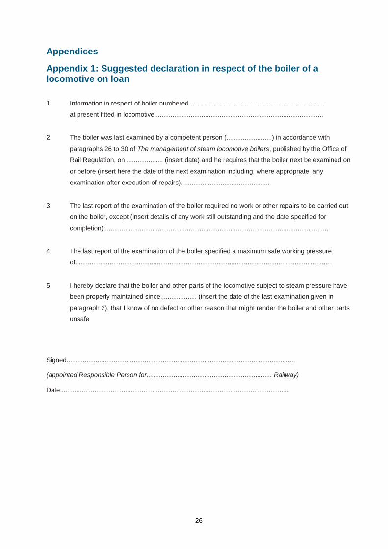
Appendix 1: Suggested declaration in respect of the boiler of a locomotive on loan 1 Information in respect of boiler numbered......................................................................….
at present fitted in locomotive.............................................................................................
2 The boiler was last examined by a competent person (.........................) in accordance with
paragraphs 26 to 30 of The management of steam locomotive boilers, published by the Office of
Rail Regulation, on .................... (insert date) and he requires that the boiler next be examined on
or before (insert here the date of the next examination including, where appropriate, any
examination after execution of repairs). ...............................................
3 The last report of the examination of the boiler required no work or other repairs to be carried out
on the boiler, except (insert details of any work still outstanding and the date specified for
completion):...........................................................................................................................
4 The last report of the examination of the boiler specified a maximum safe working pressure
of.............................................................................................................................................
5 I hereby declare that the boiler and other parts of the locomotive subject to steam pressure have
been properly maintained since.................... (insert the date of the last examination given in
paragraph 2), that I know of no defect or other reason that might render the boiler and other parts
unsafe
Signed..............................................................................................................................
(appointed Responsible Person for..................................................................... Railway)
Date..............................................................................................................................
26
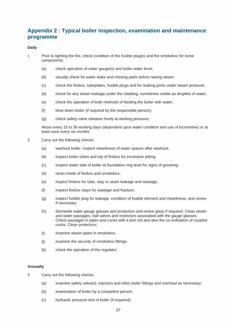
Appendix 2 : Typical boiler inspection, examination and maintenance programme Daily
1 Prior to lighting the fire, check condition of the fusible plug(s) and the smokebox for loose components:
(a) check operation of water gauge(s) and boiler water level;
(b) visually check for water leaks and missing parts before raising steam;
(c) check the firebox, tubeplates, fusible plugs and for leaking joints under steam pressure;
(d) check for any steam leakage under the cladding, sometimes visible as droplets of water;
(e) check the operation of both methods of feeding the boiler with water;
(f) blow down boiler (if required by the responsible person);
(g) check safety valve releases freely at working pressure;
About every 15 to 30 working days (dependent upon water condition and use of locomotive) or at least once every six months
2 Carry out the following checks:
(a) washout boiler, inspect cleanliness of water spaces after washout;
(b) inspect boiler tubes and top of firebox for excessive pitting;
(c) inspect water side of boiler at foundation ring level for signs of grooving;
(d) clean inside of firebox and smokebox;
(e) inspect firebox for tube, stay or seam leakage and wastage;
(f) inspect firebox stays for wastage and fracture;
(g) inspect fusible plug for leakage, condition of fusible element and cleanliness, and renew if necessary.
(h) dismantle water-gauge glasses and protectors and renew glass if required. Clean steam and water passages, ball valves and restrictors associated with the gauge glasses. Check passages in pipes and cocks with a test rod and also the co-ordination of coupled cocks. Clean protectors;
(i) examine steam pipes in smokebox;
(j) examine the security of smokebox fittings;
(k) check the operation of the regulator.
Annually
3 Carry out the following checks:
(a) examine safety valve(s), injectors and other boiler fittings and overhaul as necessary;
(b) examination of boiler by a competent person;
(c) hydraulic pressure test of boiler (if required);
27
(d) check calibration of pressure gauge;
(e) remove and examine fusible plugs.
Boiler overhaul
4 In addition to the examinations and maintenance listed above, the following items will need attention at intervals and may be grouped together at an overhaul:
(a) complete examination of the inside and outside of the boiler shell and firebox, entailing removal of all tubes and cladding and lifting the boiler from the locomotive frame where necessary, e.g. on narrow firebox locomotives;
(b) examine all steam pipes;
(c) anneal and examine all copper pipes;
(d) overhaul all boiler fittings.
28
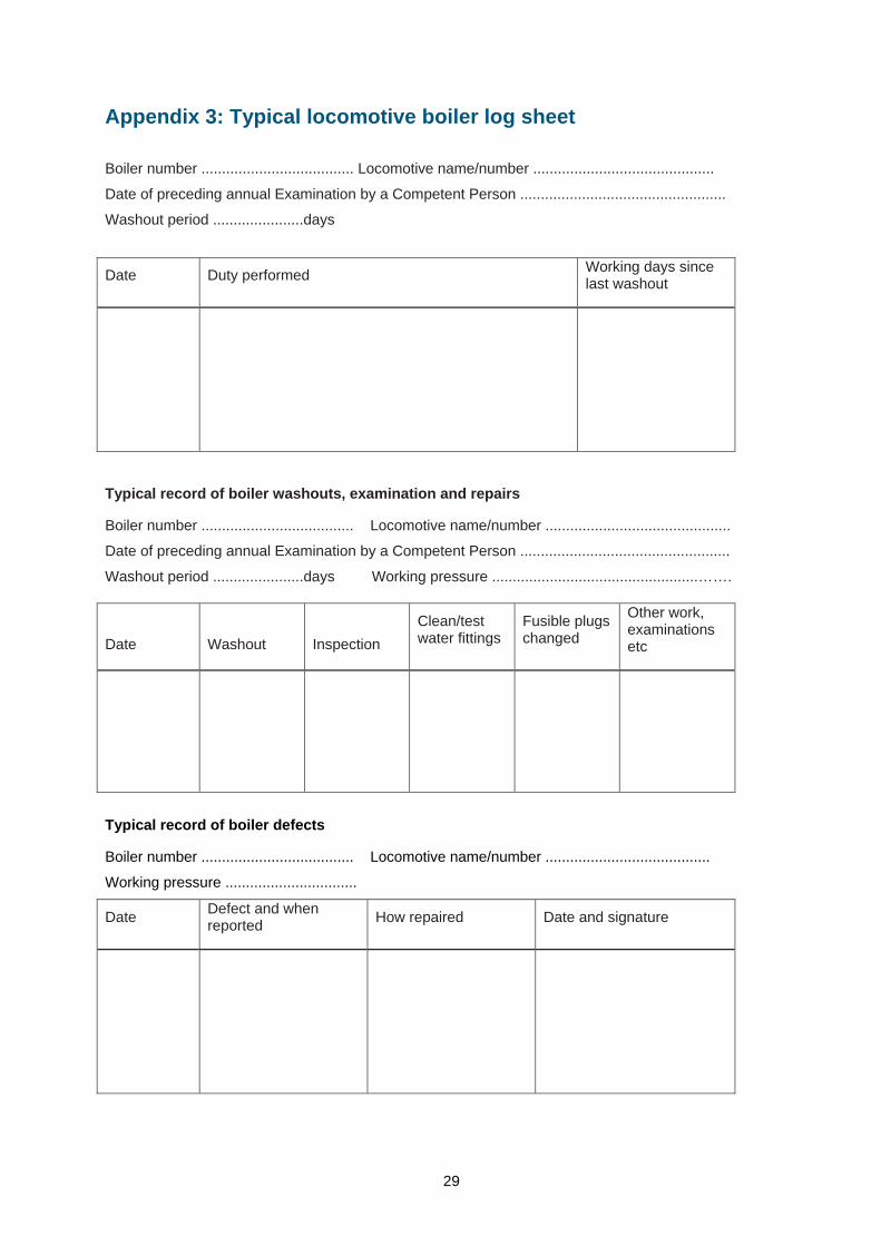
Appendix 3: Typical locomotive boiler log sheet
Boiler number ..................................... Locomotive name/number ............................................
Date of preceding annual Examination by a Competent Person ..................................................
Washout period ......................days
Date Duty performed Working days since last washout
Typical record of boiler washouts, examination and repairs
Boiler number ..................................... Locomotive name/number .............................................
Date of preceding annual Examination by a Competent Person ...................................................
Washout period ......................days Working pressure ..................................................…….
Date
Washout
Inspection Clean/test water fittings
Fusible plugs changed
Other work, examinations etc
Typical record of boiler defects
Boiler number ..................................... Locomotive name/number ........................................
Working pressure ................................
Defect and when reported How repaired Date and signature Date
29
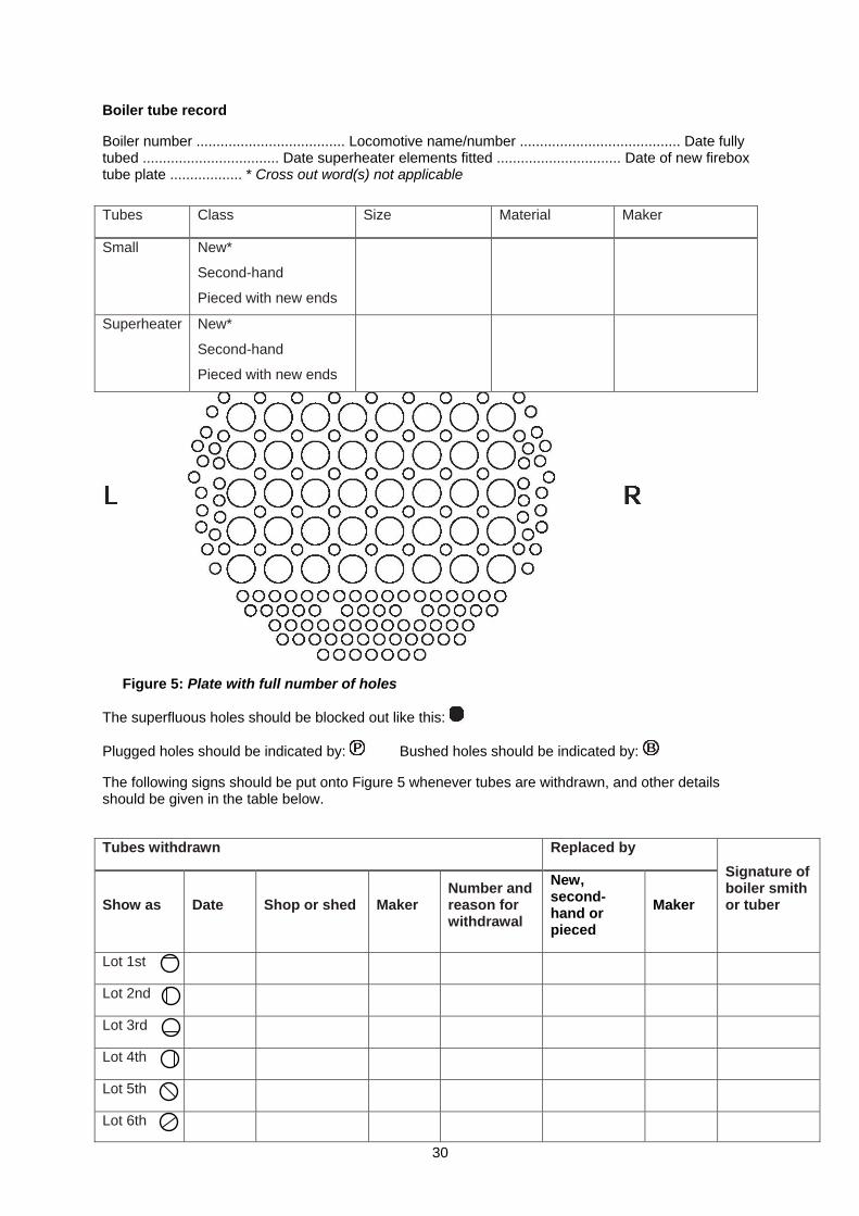
Boiler tube record
Boiler number ..................................... Locomotive name/number ........................................ Date fully tubed .................................. Date superheater elements fitted ............................... Date of new firebox tube plate .................. * Cross out word(s) not applicable
Tubes Class Size Material Maker
Small New*
Second-hand
Pieced with new ends
Superheater New*
Second-hand
Pieced with new ends
Figure 5: Plate with full number of holes
The superfluous holes should be blocked out like this:
Plugged holes should be indicated by: Bushed holes should be indicated by:
The following signs should be put onto Figure 5 whenever tubes are withdrawn, and other details should be given in the table below.
Tubes withdrawn Replaced by
Show as Date Shop or shed Maker Number and reason for withdrawal
New, second-hand or pieced
Maker
Signature of boiler smith or tuber
Lot 1st
Lot 2nd
Lot 3rd
Lot 4th
Lot 5th
Lot 6th
30
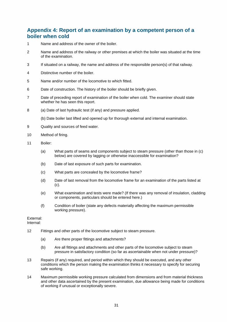
Appendix 4: Report of an examination by a competent person of a boiler when cold 1 Name and address of the owner of the boiler.
2 Name and address of the railway or other premises at which the boiler was situated at the time of the examination.
3 If situated on a railway, the name and address of the responsible person(s) of that railway.
4 Distinctive number of the boiler.
5 Name and/or number of the locomotive to which fitted.
6 Date of construction. The history of the boiler should be briefly given.
7 Date of preceding report of examination of the boiler when cold. The examiner should state whether he has seen this report.
8 (a) Date of last hydraulic test (if any) and pressure applied.
(b) Date boiler last lifted and opened up for thorough external and internal examination.
9 Quality and sources of feed water.
10 Method of firing.
11 Boiler:
(a) What parts of seams and components subject to steam pressure (other than those in (c) below) are covered by lagging or otherwise inaccessible for examination?
(b) Date of last exposure of such parts for examination.
(c) What parts are concealed by the locomotive frame?
(d) Date of last removal from the locomotive frame for an examination of the parts listed at (c).
(e) What examination and tests were made? (If there was any removal of insulation, cladding or components, particulars should be entered here.)
(f) Condition of boiler (state any defects materially affecting the maximum permissible working pressure).
External: Internal:
12 Fittings and other parts of the locomotive subject to steam pressure.
(a) Are there proper fittings and attachments?
(b) Are all fittings and attachments and other parts of the locomotive subject to steam pressure in satisfactory condition (so far as ascertainable when not under pressure)?
13 Repairs (if any) required, and period within which they should be executed, and any other conditions which the person making the examination thinks it necessary to specify for securing safe working.
14 Maximum permissible working pressure calculated from dimensions and from material thickness and other data ascertained by the present examination, due allowance being made for conditions of working if unusual or exceptionally severe.
31

Appendix 5: Report of an examination by a competent person of a boiler under normal steam pressure 1 Name and address of the owner of the boiler.
2 Name and address of the railway or other premises at which the boiler was situated at the time of the examination.
3 If situated on a railway, the name and address of the responsible person(s) of that railway.
4 Distinctive number of the boiler.
5 Name and/or number of the locomotive to which fitted.
6 Condition (external).
7 Fittings and other parts of the locomotive subject to steam pressure:
(a) Is the safety valve adjusted so as to prevent the boiler being worked at a pressure greater than the maximum permitted working pressure specified in the previous report of examination of the boiler when cold?
(b) Is the pressure gauge working correctly?
(c) Is the pressure gauge marked to correctly show the maximum permissible pressure?
(d) Is the water gauge in proper working order?
8 Repairs required before steam pressure may be raised in the boiler.
9 Other repairs (if any) required, and period within which they should be executed, and any other conditions which the person making the examination thinks it necessary to specify for securing safe working.
10 Other observations.
I certify that on..................….. I examined the above-mentioned boiler, including its fittings, attachments
and other parts of the locomotive subject to steam pressure, and that the above is a true report of the
result. It can continue to be steamed under normal operation conditions and pressure until..................….
Signature....................................................... Position in company or association ..............................................……………....
Counter signature and title of offical of company or association ......................................................................................................
Address ....................................................... Name of company or association ……………………….
..................................................................... .............................…………………………………………
..................................................................... .......................................................................................
..................................................................... Date ...............................................................................
32
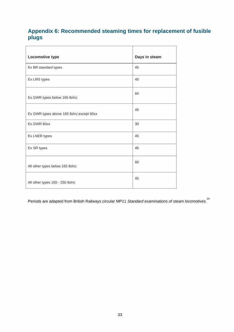
Appendix 6: Recommended steaming times for replacement of fusible plugs
Locomotive type
Days in steam
Ex BR standard types 45
Ex LMS types 45
Ex GWR types below 165 lb/in2 60
45
Ex GWR types above 165 lb/in2 except 60xx
Ex GWR 60xx 30
Ex LNER types 45
Ex SR types 45
All other types below 165 lb/in2 60
45
All other types 165 - 250 lb/in2
Periods are adapted from British Railways circular MP11 Standard examinations of steam locomotives.24
33
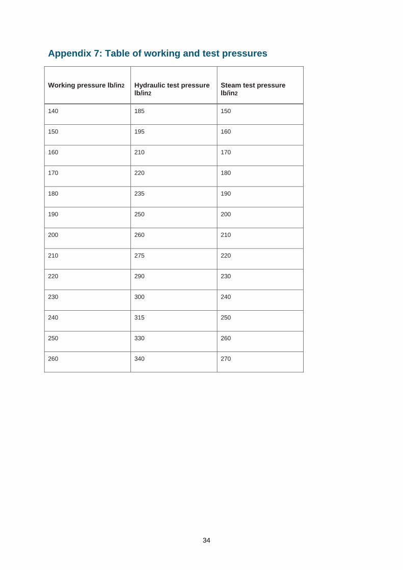
Appendix 7: Table of working and test pressures
Hydraulic test pressure lb/in2
Working pressure lb/in2 Steam test pressure lb/in2
140 185 150
150 195 160
160 210 170
170 220 180
180 235 190
190 250 200
200 260 210
210 275 220
220 290 230
230 300 240
240 315 250
250 330 260
260 340 270
34
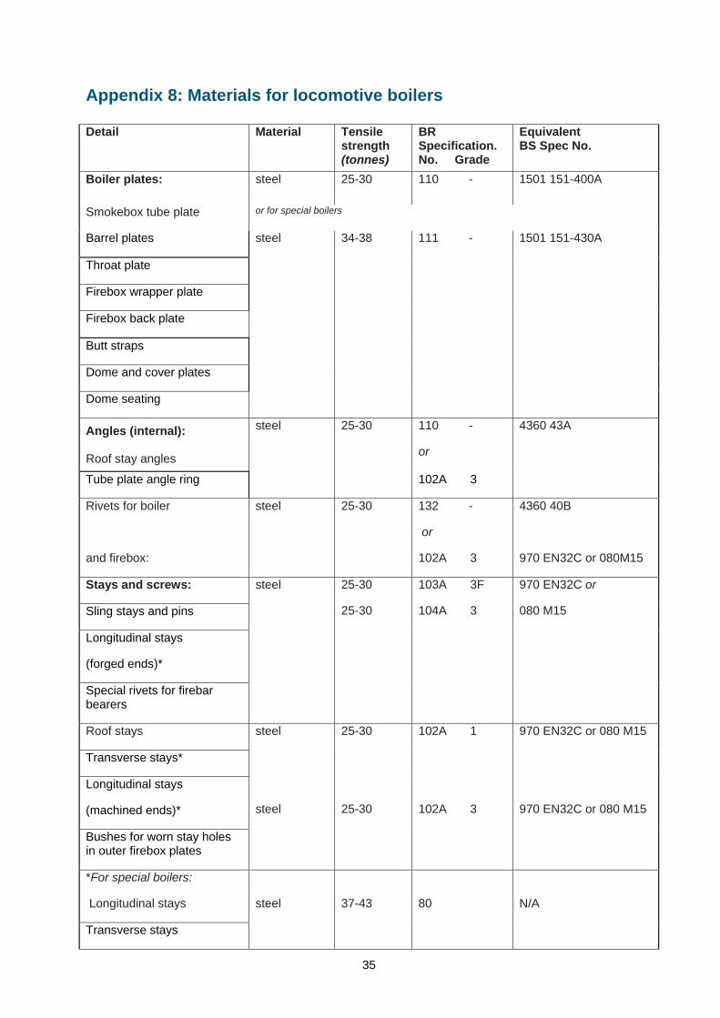
Appendix 8: Materials for locomotive boilers Detail Material Tensile
strength BR Specification. No. Grade
Equivalent BS Spec No.
(tonnes) steel 25-30 110 - Boiler plates: 1501 151-400A
Smokebox tube plate or for special boilers
Barrel plates
Throat plate
Firebox wrapper plate
Firebox back plate
Butt straps
Dome and cover plates
Dome seating
steel 34-38 111 - 1501 151-430A
Angles (internal): Roof stay angles
110 -
or
Tube plate angle ring
steel 25-30
102A 3
4360 43A
Rivets for boiler
and firebox:
steel 25-30 132 -
or
102A 3
4360 40B
970 EN32C or 080M15
Stays and screws:
Sling stays and pins
Longitudinal stays
(forged ends)*
Special rivets for firebar bearers
steel 25-30
25-30
103A 3F
104A 3
970 EN32C or
080 M15
Roof stays
Transverse stays*
Longitudinal stays
(machined ends)*
steel
Bushes for worn stay holes in outer firebox plates
steel
25-30
102A 1
102A 3
970 EN32C or 080 M15
25-30 970 EN32C or 080 M15
*For special boilers:
Longitudinal stays
Transverse stays
steel 37-43 80 N/A
35
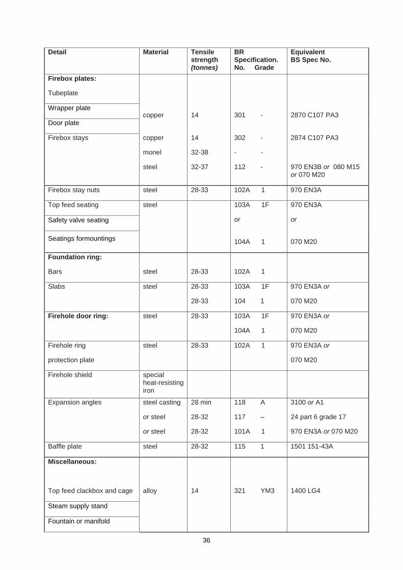
Detail Material Tensile strength (tonnes)
BR Specification. No. Grade
Equivalent BS Spec No.
Firebox plates:
Tubeplate
Wrapper plate
Door plate
copper
14
301 -
2870 C107 PA3
Firebox stays copper
monel
steel
14
32-38
32-37
302 -
- -
112 -
2874 C107 PA3
970 EN3B or 080 M15 or 070 M20
Firebox stay nuts steel 28-33 102A 1 970 EN3A
Top feed seating
Safety valve seating
Seatings formountings
steel 103A 1F
or
104A 1
970 EN3A
or
070 M20
Foundation ring:
Bars steel 28-33 102A 1
Slabs steel 28-33
28-33
103A 1F
104 1
970 EN3A or
070 M20
Firehole door ring: steel 28-33 103A 1F
104A 1
970 EN3A or
070 M20
Firehole ring
protection plate
steel 28-33 102A 1 970 EN3A or
070 M20
Firehole shield special heat-resisting iron
Expansion angles steel casting
or steel
or steel
28 min
28-32
28-32
118 A
117 –
101A 1
3100 or A1
24 part 6 grade 17
970 EN3A or 070 M20
Baffle plate steel 28-32 115 1 1501 151-43A
Miscellaneous:
Top feed clackbox and cage
Steam supply stand
Fountain or manifold
alloy
14
321 YM3
1400 LG4
36
Detail Material Tensile strength (tonnes)
BR Specification. No. Grade
Equivalent BS Spec No.
Regulator stuffing box
Gland for stuffing box
Regulator valve
Water gauges
Whistle
Steam valves for:
Injectors
Brakes
Sanding
Carriage warming
Ejectors
Pressure gauge
Blower
Whistle
Lubricator
Washout plugs (cast)
Fusible plugs (cast)
Flanges for main steam pipe steel 28-33 102A 1
103A 1F
104A 1
970 EN3A
or
070 M20
Regulator rod:
Regulator links and pins
Regulator handle
steel 25-30
103A 3F
104A 3
970 EN32C or
080 M15
Boiler tubes (steel)
Superheater flue tubes steel 20-28
123 or
122
3059 PT1 320
HFS/CFS or ERW
Superheater elements steel 20-28 123 or
122
3059 PT1 320 or
3602 HFS 320
Boiler tubes (copper): copper 14.5 min 317A - 2871 C107-PA3
37
Detail Material Tensile strength
BR Specification. No. Grade
Equivalent BS Spec No.
(tonnes) Top feed plates steel 28-32 115 1 EN10025 FE430 or
4360 43A
steel 28-33 102A 1 970 EN3A or 070 M20 Brackets and carriers
Superheater header steel casting or cast iron
28 min
14 min
118 A
cyl quality
3100 A1
1452-220
Regulator castings: cast iron 14 min cyl quality
Blocks, flanges collars for superheater elements:
steel 28-33 102A 4 970 EN3C or 070 M20
Welded pads and snubs:
Ashpan studs
Firedoor handles/levers
steel 28-33 102A 1 970 EN3A or 070 M20
Firedoor frame details
Washout doors and bridges steel 28-33 103A 4F 970 EN3A or 070 M20
Pipes in smokebox
Miscellaneous pipes steel 20-28 122 3602 HFS 320
Main steam pipes
Superheated engines steel 20-28 122 3602 HFS 320
Saturated engines copper 14.5 min 316 2871 C107 PA3
Steel pipe ends and flanges steel 28-33 103A 1 970 EN3A or 070 M20
Flanges for copper pipe alloy 321 YM5 1400 SC B6
Elbows and misc. valves alloy 14 321 YM3 1400 LG4
Copper pipes copper 14.5 min 316 2871 C106
Flanges for copper pipes alloy YM5 1400 SC B6
Flanges for steel pipes steel 28-33 102A 1 970 EN3A or 070 M20
Fastenings:
Black bolts and studs steel 28-33 102A 1 970 EN3A or 070 M20
Turned bolts and studs steel 28-33 102A 1 970 EN3A or 070 M20
Bolts/studs for superheater elements and joints
steel 32-38 102A 5
970 EN3A or 070 M20
38
Detail Material Tensile strength
BR Specification. No. Grade
Equivalent BS Spec No.
(tonnes) Nuts for:
Firebox stays steel 28-33 102A 1 970 EN3A or 070 M20
Superheater element joints steel 28-33 102A 4 970 EN3A or 070 M20
General purpose black and bright
steel 28-33 102A 1 970 EN3A or 070 M20
Cones for pipe unions alloy 321 YM5 1400 SC B6
Union nuts alloy 14 321 YM3 1400 LG4
Information from British Transport Commission document Materials for locomotives and tenders.25
39
References and further reading References
1 British Railways London Midland Region Chief Mechanical and Electrical Engineers Instructions Relative to Boilers, British Railways Board 1959, updated and amended 1965
2 Pressure Systems Safety Regulations 2000, SI 2000/128 The Stationery Office 2000 ISBN 0 11 085836 0
3 Safety of pressure systems. Pressure Systems Safety Regulations 2000. Approved Code of Practice L122 HSE Books 2000 ISBN 0 7176 1767 X
4 Health and Safety at Work Act 1974 Ch 37 The Stationery Office 1974 ISBN 0 10 543774 3
5 Pressure Equipment Regulations 1999 SI 1999/2001 The Stationery Office 2001 ISBN 0 11 082790 2
6 Railway Safety Publication 1: Developing and maintaining staff competence http://www.rail-reg.gov.uk/upload/pdf/sf-dev-staff.pdf
7 BS 2486: 1997 Recommendations for treatment of water for steam boilers and water heaters British Standards Institution
8 BS 1400: 1985 Specification for copper alloy ingots and copper alloy and high conductivity copper castings British Standards Institution
9 BS EN 1982: 1999 Copper and copper alloys. Ingots and castings British Standards Institution
10 Control of Lead at Work Regulations 2002 SI 2002/2676 The Stationery Office 2002 ISBN 0 11 042971 6
11 Control of lead at work. Control of Lead at Work Regulations 2002. Approved Code of Practice and guidance L132 (Third edition) HSE Books 2002 ISBN 0 7176 2565 6
12 Control of Substances Hazardous to Health Regulations 2002 SI 2002/2677 The Stationery Office 2002 ISBN 0 11 042919 2
13 Control of substances hazardous to health. The Control of Substances Hazardous to Health Regulations 2002. Approved Code of Practice and guidance L5 (Fourth edition) HSE Books 2002 ISBN 0 7176 2534 6
14 Control of Asbestos at Work Regulations 2002 SI 2002/2675 The Stationery Office 2002 ISBN 0 11 042918 4
15 BS EN 10216-1: 2002 Seamless steel tubes for pressure purposes. Technical delivery conditions. Non-alloy steel tubes with specified room temperature properties British Standards Institution
16 BS EN 10217-1: 2002 Welded steel tubes for pressure purposes. Technical delivery conditions. Non-alloy steel tubes with specified room temperature British Standards Institution
17 BS 2870: 1980 Specification for rolled copper and copper alloys: sheet, strip and foil British Standards Institution
18 BS EN 1653: 1998 Copper and copper alloys. Plate sheet and circles for boilers, pressure vessels and hot water storage units British Standards Institution
19 Safety in pressure testing General Guidance Note GS4 (Third edition) HSE Books 1998 ISBN 0 7176 1629 0
20 Control of Asbestos Regulations 2006 SI 2006/2739 The Stationery Office 2006
21 Control of Pollution (Special Waste) (Amended) Regulations 1988 SI 1988/1790 The Stationery Office 1988 ISBN 0 11 087790 X
40
22 Reporting of Injuries, Diseases and Dangerous Occurrences Regulations 1995 SI 1995/3163 The Stationery Office 1995 ISBN 0 11 053751 3
23 Asbestos (Prohibitions) (Amendment) Regulations 1999 SI 1999/2373 The Stationery Office 1999 ISBN 0 11 085167 6
24 British Railways Board circular MP11 Standard examinations of steam locomotives British Railways Board
25 British Transport Commission London Midland Region Materials for locomotives and tenders British Transport Commission
Further reading
Written schemes of examination: Pressure Systems Safety Regulations 2000 Leaflet INDG178(rev1) HSE Books 2002 (single copy free or priced packs of 15 ISBN 0 7176 2269 X)
Safe work in confined spaces. Confined Spaces Regulations 1997. Approved Code of Practice, Regulations and guidance L101 HSE Books 1997 ISBN 0 7176 1405 0
Safe work in confined spaces Leaflet INDG258 HSE Books 1997 (single copy free or priced packs of 20 ISBN 0 7176 1442 5)
Railways and Other Transport Systems (Approval of Works, Plant and Equipment) Regulations 1994 SI 1994/157 The Stationery Office 1994 ISBN 0 11 043157 X
Mines and Quarries Act 1954 Ch 70 The Stationery Office 1954
Handbook for Railway Steam Locomotive Enginemen British Transport Commission 1957, reprinted by Ian Allan Ltd 1998 ISBN 0711006288
BS 970-1: 1996 Specification for wrought steels for mechanical and allied engineering purposes. General inspection and testing procedures and specific requirements for carbon, carbon manganese, alloy and stainless steels British Standards Institution
BS 2633: 1987 Specification for Class 1 arc welding of ferritic steel pipework for carrying fluids British Standards Institution
BS 2871 Part 1: 1971 Specification copper and copper alloys. Tube Copper tubes for water, gas and sanitation British Standards Institution
41

Further information
HSE priced and free publications are available by mail order from HSE Books, PO Box 1999, Sudbury, Suffolk CO10 2WA Tel: 01787 881165 Fax: 01787 313995 Website: www.hsebooks.co.uk (HSE priced publications are also available from bookshops and free leaflets can be downloaded from HSE’s website: www.hse.gov.uk)
British Standards are available from BSI Customer Services, 389 Chiswick High Road, London W4 4AL Tel: 020 8996 9001 Fax: 020 8996 7001 Website: www.bsi-global.com
The Stationery Office publications are available from: The Stationery Office, PO Box 29, Norwich NR3 1GN Tel: 0870 600 5522 Fax: 0870 600 5533 e-mail: [email protected] Website: www.tso.co.uk (They are also available from bookshops)
This leaflet contains notes on good practice which are not compulsory but which you may find helpful in considering what you need to do.
© Crown copyright This publication may be freely reproduced, except for advertising, endorsement or commercial purposes. First published 2005. Revised and web version published October 2007.
42