the perpetual motion machine - uni-potsdam.de
TRANSCRIPT

Honeypot Architectures for IPv6 Networks
Dissertation
eingereicht von
Dipl.-Inf. Sven Schindler
vorgelegt derMathematisch-Naturwissenschaftlichen Fakultät
der Universität Potsdamzur Erlangung des Akademischen Grades
Doktor der Naturwissenschaften- Dr. rer. nat. -
angefertigt am
Institut für Informatik und Computational ScienceProfessur Betriebssysteme und Verteilte Systeme
Betreuung:Prof. Dr. Bettina Schnor
Potsdam, den 28. November 2016

Schindler, [email protected] Architectures for IPv6 NetworksDissertation, Institut für Informatik und Computational SciencePotsdam University, November 2016

Writing a dissertation is not an easy task. Besides the writer’s effortand endurance, it affects a lot of surrounding people. I would like touse this paragraph to thank all the people who accompanied me on thisway. First of all, I would like to thank all members of our IPv6 researchgroup at the University of Potsdam, especially Prof. Dr. Bettina Schnorand Prof. Dr. Thomas Scheffler, not only for their scientific and techni-cal assistance but also for their moral support. Together, we had countlessconstructive discussions and developed plenty of interesting concepts andideas. I would further like to thank the German internet service providerStrato AG, especially Wilhelm Boeddinghaus and Christian Seitz, forproviding the required infrastructure for a number of darknet experimentsand for sharing their network expertise. I also want to say thank you tomy colleagues and friends at Immobilien Scout. They gave me the re-quired time for research and conferences and endured me on workingdays where early morning research had already exhausted my concentra-tion. I would further like to thank my partner Franzi for her never-endingsupport. We missed many weekends together and experienced a lot ofearly mornings in order to finish my work. This thesis would not havebeen possible without her understanding and tolerance, I really appreci-ate this. I don’t want to forget to say thank you to all of my family andfriends. I skipped quite some get-togethers in order get my work doneand they always showed tolerance and gave me the required moral sup-port.

Abstract
The decrease of available IPv4 addresses and the requirement for new features demands Internetservice providers to deploy IPv6 networks. It is not a question of if, but when new networkattacks will appear, which target the comparatively new network protocol. Virtual honeypotsprovide an important tool for the observation of assaults in computer networks. In contrast tointrusion detection systems, honeypots interact with an attacker and therefore allow the creationof fine-grained evaluations of attack sequences. This thesis focuses on honeypot architectureswhich are specialized in the observation of IPv6 network attacks. A survey of existing honeypotsolutions reveals a need for IPv6-specific honeypots with support for large IPv6 address spaces.Long-term observations of two different darknets prove that IPv6 networks are not free of unin-tended activity. Large-scale network scans search through vast and unforeseeable address rangesto find and explore new IPv6-enabled hosts.This thesis proposes two different honeypot architectures and presents the corresponding proto-type implementations, called Honeydv6 and Hyhoneydv6, to overcome the need for IPv6 hon-eypot solutions. Honeydv6 is a low-interaction honeypot which is able to simulate entire IPv6networks to efficiently observe network scan approaches and assaults. It extends the well-knownlow-interaction honeypot solution Honeyd with a custom IPv6 stack and a new dynamic honey-pot instantiation mechanism. The utilization of a custom network stack implementation allowsHoneydv6 to simulate multiple hosts with different IPv6 addresses on a single host and to ob-serve even low-level IPv6 attacks, such as assaults to the IPv6 fragmentation mechanism. Thedynamic instantiation mechanism spawns new low-interaction honeypots on-demand based onattackers’ destinations. This approach allows Honeydv6 to cover large IPv6 address spaces andto respond to attacks that target arbitrary IPv6 address ranges.Low-interaction honeypots only simulate network services up to a certain degree of granular-ity. For complex attack scenarios where authentic network services are a requirement, low-interaction honeypots may not suffice and a deployment of high-interaction honeypots becomesnecessary. However, the vast IPv6 address space makes classical high-interaction honeypot de-ployment strategies impossible and new architectural approaches are required. Hyhoneydv6 wasdesigned to efficiently allow the deployment of high-interaction honeypots in IPv6 networks. Incontrast to Honeydv6, Hyhoneydv6 is a hybrid honeypot framework which includes a combina-tion of low- and virtual machine-based high-interaction honeypots. Low-interaction honeypotsin the Hyhoneydv6 architecture process network scans and attacks to less complex network ser-vices. High-interaction honeypots focus on the processing of attacks to complex and proprietarynetwork services. The Hyhoneydv6 architecture includes a newly developed proxy mechanismwhich allows to transparently forward attackers from low- to high-interaction honeypots. Hy-honeydv6 adapts the dynamic low-interaction honeypot instantiation mechanism of Honeydv6to dynamically deploy high-interaction honeypots. This includes an on-demand address recon-figuration of high-interaction honeypot instances.The performance measurements of the Honeydv6 and the Hyhoneydv6 prototype implementa-tion show that both architectures do not rely on expensive infrastructures and can be run onoff-the-shelf hardware.

Contents
1 Introduction 11.1 Motivation . . . . . . . . . . . . . . . . . . . . . . . . . . . . . . . . . . . . . 31.2 Thesis Outline . . . . . . . . . . . . . . . . . . . . . . . . . . . . . . . . . . . 41.3 Publications . . . . . . . . . . . . . . . . . . . . . . . . . . . . . . . . . . . . 4
2 Background 72.1 IPv6 . . . . . . . . . . . . . . . . . . . . . . . . . . . . . . . . . . . . . . . . 7
2.1.1 Address Format and Scopes . . . . . . . . . . . . . . . . . . . . . . . 72.1.2 Base Header Format . . . . . . . . . . . . . . . . . . . . . . . . . . . 82.1.3 Extension Header . . . . . . . . . . . . . . . . . . . . . . . . . . . . . 92.1.4 IPv6 Neighbor Discovery . . . . . . . . . . . . . . . . . . . . . . . . . 102.1.5 Stateless IPv6 Autoconfiguration . . . . . . . . . . . . . . . . . . . . . 112.1.6 IPv6 Privacy Extensions . . . . . . . . . . . . . . . . . . . . . . . . . 13
2.2 Remote IPv6 Attacks . . . . . . . . . . . . . . . . . . . . . . . . . . . . . . . 132.2.1 Classification Scheme . . . . . . . . . . . . . . . . . . . . . . . . . . 142.2.2 Attacks on IPv6 Extension Headers . . . . . . . . . . . . . . . . . . . 152.2.3 Attacks on the IPv6 Fragmentation Mechanism . . . . . . . . . . . . . 182.2.4 Attacks on the IPv6 Flow Label . . . . . . . . . . . . . . . . . . . . . 21
2.3 IPv6 Network Scan Approaches . . . . . . . . . . . . . . . . . . . . . . . . . 232.4 Darknets . . . . . . . . . . . . . . . . . . . . . . . . . . . . . . . . . . . . . . 242.5 Honeypots . . . . . . . . . . . . . . . . . . . . . . . . . . . . . . . . . . . . . 24
3 Related Work 273.1 Prior IPv6 Darknet Experiments . . . . . . . . . . . . . . . . . . . . . . . . . 273.2 Low-interaction Honeypots . . . . . . . . . . . . . . . . . . . . . . . . . . . . 293.3 High-interaction Honeypots . . . . . . . . . . . . . . . . . . . . . . . . . . . . 303.4 Hybrid Honeypots . . . . . . . . . . . . . . . . . . . . . . . . . . . . . . . . . 313.5 Large-scale Honeyfarms . . . . . . . . . . . . . . . . . . . . . . . . . . . . . 363.6 Survey of Hybrid Honeypots and Large-scale Honeyfarms . . . . . . . . . . . 40
4 IPv6 Network Attack Monitoring with Honeydv6 474.1 Adapting the Configuration of Virtual Hosts . . . . . . . . . . . . . . . . . . . 484.2 Implementing a custom IPv6 Network Stack . . . . . . . . . . . . . . . . . . . 494.3 Pitfalls . . . . . . . . . . . . . . . . . . . . . . . . . . . . . . . . . . . . . . . 564.4 Covering huge Address Spaces using Random IPv6 Request Processing . . . . 584.5 Tricking Nmap’s IPv6 Operating System Fingerprinting . . . . . . . . . . . . . 59
i
4.5.1 Fingerprinting in IPv4 Networks . . . . . . . . . . . . . . . . . . . . . 604.5.2 Fingerprinting in IPv6 Networks . . . . . . . . . . . . . . . . . . . . . 624.5.3 Implementation of an IPv6 Personality Engine for Honeydv6 . . . . . . 65
4.6 Honeydv6 Performance Evaluation . . . . . . . . . . . . . . . . . . . . . . . . 694.6.1 IPv4 and IPv6 Throughput Comparison . . . . . . . . . . . . . . . . . 694.6.2 Scalability of Honeydv6 . . . . . . . . . . . . . . . . . . . . . . . . . 704.6.3 User Tests . . . . . . . . . . . . . . . . . . . . . . . . . . . . . . . . . 71
4.7 Summary . . . . . . . . . . . . . . . . . . . . . . . . . . . . . . . . . . . . . 71
5 IPv6 Darknet Observations 735.1 Nine Months of IPv6 Traffic Monitoring in a /48 darknet . . . . . . . . . . . . 73
5.1.1 Darknet Setup . . . . . . . . . . . . . . . . . . . . . . . . . . . . . . . 735.1.2 Automatic Traffic Analysis . . . . . . . . . . . . . . . . . . . . . . . . 735.1.3 Observed Traffic . . . . . . . . . . . . . . . . . . . . . . . . . . . . . 745.1.4 Summary . . . . . . . . . . . . . . . . . . . . . . . . . . . . . . . . . 76
5.2 Seventeen Months of IPv6 Traffic Monitoring in a /34-Network . . . . . . . . . 765.2.1 Darknet setup . . . . . . . . . . . . . . . . . . . . . . . . . . . . . . . 775.2.2 Dark- and Honeynet Traffic Monitor . . . . . . . . . . . . . . . . . . . 785.2.3 Stage 1: Observations without Honeypot Service Interactions . . . . . 785.2.4 Stage 2: Observations with minimal Honeypot Interactions . . . . . . . 795.2.5 Stage 3: Observations with frequent Honeypot Interactions . . . . . . . 1005.2.6 Summary . . . . . . . . . . . . . . . . . . . . . . . . . . . . . . . . . 104
6 Hyhoneydv6 - A hybrid IPv6-Honeynet Architecture 1076.1 IPv6 Honeypot Requirements . . . . . . . . . . . . . . . . . . . . . . . . . . . 1076.2 Honeypot Distribution Strategies . . . . . . . . . . . . . . . . . . . . . . . . . 1086.3 Architecture Overview . . . . . . . . . . . . . . . . . . . . . . . . . . . . . . 1096.4 Converting Honeydv6 into a hybrid Honeypot Architecture . . . . . . . . . . . 110
6.4.1 Component Overview . . . . . . . . . . . . . . . . . . . . . . . . . . 1106.4.2 High-interaction Honeypot Manager . . . . . . . . . . . . . . . . . . . 1116.4.3 Address Reconfiguration Server . . . . . . . . . . . . . . . . . . . . . 1176.4.4 Transparent Proxy . . . . . . . . . . . . . . . . . . . . . . . . . . . . 1196.4.5 Attack Distribution . . . . . . . . . . . . . . . . . . . . . . . . . . . . 127
6.5 Summary . . . . . . . . . . . . . . . . . . . . . . . . . . . . . . . . . . . . . 127
7 Hyhoneydv6 Performance Evaluation 1297.1 Test Setup and Hardware Specifications . . . . . . . . . . . . . . . . . . . . . 1297.2 Machine Creation, Boot and Backup Time . . . . . . . . . . . . . . . . . . . . 1307.3 Address Reconfiguration and transparent Proxy . . . . . . . . . . . . . . . . . 1337.4 Throughput . . . . . . . . . . . . . . . . . . . . . . . . . . . . . . . . . . . . 1357.5 Summary . . . . . . . . . . . . . . . . . . . . . . . . . . . . . . . . . . . . . 136
8 Conclusion and Future Work 1378.1 Research Contributions . . . . . . . . . . . . . . . . . . . . . . . . . . . . . . 137
ii
8.2 Future Work . . . . . . . . . . . . . . . . . . . . . . . . . . . . . . . . . . . . 1398.2.1 Update Honeyd-based Projects . . . . . . . . . . . . . . . . . . . . . . 1398.2.2 Real-World Attack Observations and Honeypot Parameter Tuning . . . 1398.2.3 Large-Scale Darknet Experiments . . . . . . . . . . . . . . . . . . . . 140
8.3 Final Words . . . . . . . . . . . . . . . . . . . . . . . . . . . . . . . . . . . . 140
A Creating Virtual Machine Images for Hyhoneydv6 141
B Hyhoneydv6 High-Interaction Honeypot XML Configuration 143
C Darknet Traffic Capture Script 145
D Darknet Traffic Analysis Script 147
E Abbreviations 149
Bibliography 151
Index 163
iii

iv
1 Introduction
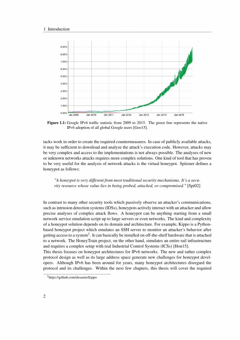
The Internet Protocol (IP) contributes an essential functionality to today’s global Internet infras-tructure. IP is probably best known for its address structure which makes packet routing and theinterconnection of multiple independent networks possible. However, the protocol introduces alot more features, such as the fragmentation of oversized network packets or the indication ofservice types [Pos81b].The Internet Protocol version 4 (IPv4) has long been the dominating protocol in the global Inter-net. However, this situation is about to change. On September 24, 2015, the IPv4 address poolof the American Registry for Internet Numbers, one of the five Regional Internet Registries,has depleted [Ame15]. A so-called IPv4 Unmet Requests Policy has been established and Inter-net Service Providers are forced to join a waiting list if they plan to acquire new IPv4 addressspaces. The German IPv6 Council is one of various groups that actively requests Internet ServiceProviders (ISPs) and organizations to migrate to the IPv4 successor IPv6 to confront the IPv4address depletion1. In contrast to 32-bit addresses of the Internet Protocol version 4, 128-bitIPv6 addresses provide a much larger address space. The IPv4 address space contains aroundfour billion addresses. Considering the address structure defined in RFC 4291, the smallest pos-sible IPv6 subnet alone contains 18,446,744,073,709,551,616 IPv6 addresses [HD06, RIP15].According to RIPE NCC, most ISPs assign each of their end users an address space that includes65,536 times the address space of this smallest possible IPv6 subnet.A Google traffic statistic, shown in Figure 1.1, reveals that various ISPs and organizations havestarted the deployment of IPv6 within the last few years [Goo15]. From 2014 to 2015, the IPv6traffic grew more than 100 percent. In some countries, such as Belgium, the IPv6 adoptionalmost reaches 40 percent.It can be expected that the advances in the deployment of IPv6 lead to an increased numberof attacks in IPv6 networks. Besides classical attacks to upper layer protocols, the IPv6 pro-tocol design introduces new vulnerabilities which may also be a target for future attacks. In2014, a publication by Ullrich et al. presented a classification of IPv6 attacks and countermea-sures [Joh14]. Altogether, the authors listed fifty different IPv6-related vulnerabilities. Whilesome of these weaknesses are also present in IPv4 networks in a similar form, others are quiteIPv6-specific. They target particular IPv6 headers, tunneling or fragmentation methods. To-day, it is rather simple for technology enthusiastic users to execute such kind of attacks. Thereare bundled tools and scripts publicly available which almost automatically exploit most of thelisted vulnerabilities. Two well-known examples for IPv6 attack tool bundles are the THC-IPv6-Attack-Toolkit [Heu15] and the SI6 Networks’ IPv6 Toolkit [SI612]. Certainly, further gaps willbe found and new attacks occur in the future.Researchers and developers of network security tools require a deep understanding of how at-
1http://www.ipv6council.de
1
1 Introduction
Figure 1.1: Google IPv6 traffic statistic from 2009 to 2015. The green line represents the nativeIPv6 adoption of all global Google users [Goo15].
tacks work in order to create the required countermeasures. In case of publicly available attacks,it may be sufficient to download and analyze the attack’s execution code. However, attacks maybe very complex and access to the implementations is not always possible. The analyses of newor unknown networks attacks requires more complex solutions. One kind of tool that has provento be very useful for the analysis of network attacks is the virtual honeypot. Spitzner defines ahoneypot as follows:
"A honeypot is very different from most traditional security mechanisms. It’s a secu-rity resource whose value lies in being probed, attacked, or compromised." [Spi02]
In contrast to many other security tools which passively observe an attacker’s communications,such as intrusion detection systems (IDSs), honeypots actively interact with an attacker and allowprecise analyses of complex attack flows. A honeypot can be anything starting from a smallnetwork service emulation script up to large servers or even networks. The kind and complexityof a honeypot solution depends on its domain and architecture. For example, Kippo is a Python-based honeypot project which emulates an SSH server to monitor an attacker’s behavior aftergetting access to a system2. It can basically be installed on off-the-shelf hardware that is attachedto a network. The HoneyTrain project, on the other hand, simulates an entire rail infrastructureand requires a complex setup with real Industrial Control Systems (ICSs) [Hon15].This thesis focuses on honeypot architectures for IPv6 networks. The new and rather complexprotocol design as well as its large address space generate new challenges for honeypot devel-opers. Although IPv6 has been around for years, many honeypot architectures disregard theprotocol and its challenges. Within the next few chapters, this thesis will cover the required
2https://github.com/desaster/kippo
2
1.1 Motivation
IPv6 and honeypot background before introducing two new honeypot architectures which havebeen especially designed for the observation of attacks in IPv6 networks.
1.1 Motivation
In January 1980, RFC 760 [Pos80a], later replaced by RFC 791 [Pos81b], first defined the In-ternet Protocol version 4. After more than 35 years later, the number of available IPv4 networkmonitoring and security solutions is countless. Numerous and comprehensive researches, suchas the network observations published by Pang et al. [PYB+04], have been conducted to deter-mine and encounter threats in IPv4 networks.
IPv6 was first defined in December 1995 in RFC 1883 [DH95], which was obsoleted threeyears later by RFC 2460 [DH98]. Compared to its predecessor or common upper layer pro-tocols, such as TCP [Pos81c] or UDP [Pos80b], IPv6 is a relatively young protocol. One ofthe first IPv6 stack implementations was provided by the KAME project, which started in April1998 [Had02]. Although more than fifteen years have passed since then, the number of securitysolutions for IPv6 networks still falls far below the number of available IPv4 solutions. This the-sis is mainly motivated by this lack of available IPv6 network security tools. It covers differentexisting honeypot solutions and introduces new IPv6-specific honeypot architectures to remedythis deficiency and to support the observation of attacks in IPv6 networks.
The lack of IPv6 security tools is certainly one reason for the shortcoming in IPv6 network expe-rience. Few research has been conducted to determine the activity and the current threat level inIPv6 networks. Ford et al. conducted one of the first so-called IPv6 darknet experiments, wherethey observed the activity within an unused IPv6 address space for multiple months [FSR06].The experiment started in December 2004, almost ten years after the initial specification of IPv6.At this time, no threats could be identified. However, the utilized 48-bit address space was rela-tively small in comparison to the address space that IPv6 has to offer. More than five years later,Huston and Czyz et al. started further observations in larger address spaces [Hus10, CLM+13].Back then, the authors of these experiments came to the same conclusion, that the IPv6 addressspace is mostly free of threats and that uncommon traffic is mainly caused by misconfiguration.The increase of IPv6 traffic within the last few years may have changed this situation. A majoraim of this thesis is to gain a better understanding of the kind of network traffic that can beexpected in IPv6 networks. With the support of further darknet experiments, this thesis deter-mines the current threat level in IPv6 networks to enhance the development of IPv6 networksecurity tools. A special focus of the traffic observations lies on the approaches that are usedby attackers to locate hosts in IPv6 networks. Most of the previous experiments provided broadand well prepared traffic statistics. However, they did not go into the details about the behaviorof individual sources. Gont and Chown presented several ways to reduce the search space inIPv6 networks because the vast IPv6 address space makes brute-force network scans basicallyimpossible [GC15]. It is still unknown whether attackers actually apply these approaches to findhosts in the vast IPv6 address space. This thesis addresses these questions and shows how IPv6honeypots and darknets can be used to retrieve the corresponding answers.
3
1 Introduction
1.2 Thesis Outline
The thesis comprises the following chapters:
Chapter 2: Background provides an introduction into the Internet Protocol version 6 (IPv6).Besides the essential structure and functionality of IPv6, the chapter presents possible IPv6 net-work scan approaches and a classification of remote IPv6 network attacks. This is followed byan introduction into darknets and honeypots to support the observation of network attacks.
Chapter 3: Related Work discusses related darknet experiments and honeypot projects. Thechapter furthermore surveys hybrid honeypot and large-scale honeyfarm solutions to evaluatetheir applicability in IPv6 networks.
Chapter 4: IPv6 Network Attack Monitoring with Honeydv6 presents the architecture, implemen-tation and performance evaluation of the low-interaction honeypot framework Honeydv6, whichcan be used to simulated entire IPv6 networks on a single host. It introduces a new request han-dling approach which allows honeypots to cover entire IPv6 networks with a single machine.
Chapter 5: IPv6 Darknet Observations shows the results of two IPv6 darknet experiments. Thechapter analyses and highlights observed IPv6 network scan approaches and evaluates the cur-rent threat level in IPv6 networks.
Chapter 6: Hyhoneydv6 - A hybrid IPv6-Honeynet Architecture introduces the hybrid honey-pot architecture Hyhoneydv6. The architecture was designed to provide authentic network ser-vices in large-scale IPv6 networks. The chapter discusses strategies for the distribution of high-interaction honeypots in IPv6 networks and presents the implementation of a dynamic high-interaction honeypot instantiation mechanism.
Chapter 7: Hyhoneydv6 Performance Evaluation presents performance measurement resultsof Hyhoneydv6. Chapter 7 proves that the proposed architecture can efficiently deploy high-interaction honeypots in large IPv6 networks on off-the-shelf hardware to provide an authenticenvironment for IPv6 network attacks.
Chapter 8: Conclusion and Future Work summarizes the results of this thesis and highlightsadditional topics for future work.
1.3 Publications
Major contributions of this thesis have been presented at international conferences:
• Sven Schindler, Bettina Schnor, Simon Kiertscher, Thomas Scheffler, and Eldad Zack.HoneydV6: A low-interaction IPv6 honeypot. In 10th International Conference on Secu-rity and Cryptography (SECRYPT), Reykjavik, Iceland, 2013.
4
1.3 Publications
• Sven Schindler, Bettina Schnor, Simon Kiertscher, Thomas Scheffler, and Eldad Zack.IPv6 network attack detection with HoneydV6. In Mohammad S. Obaidat and JoaquimFilipe, editors, E-Business and Telecommunications, volume 456, pages 252–269. SpringerPress, 2014. ISBN: 978-3-662-44787-1.
• Sven Schindler, Oliver Eggert, Bettina Schnor, and Thomas Scheffler. Shellcode Detec-tion in IPv6 Networks with HoneydV6. In 11th International Conference on Security andCryptography (SECRYPT), Vienna, Austria, 2014.
• Sven Schindler, Thomas Scheffler, and Bettina Schnor. Taming the IPv6 Address Spacewith Hyhoneydv6. In Proceedings of the World Congress on Internet Security (WorldCIS),Dublin, Ireland, 2015, received Best Paper Award.
• Sven Schindler, Bettina Schnor, and Thomas Scheffler. Hyhoneydv6: A hybrid HoneypotArchitecture for IPv6 Networks. International Journal of Intelligent Computing Research(IJICR), 6(2):570–578, 2015. ISSN: 2042-4655.
5

1 Introduction
6

2 Background
IPv6 was mainly developed to encounter the problem of insufficient addresses in IPv4 networks.However, IPv6 is not just an extended version of IPv4 but a complete redesign that providesnew features. The protocol induces new challenges, not only for attackers, but also for operatorsand developers of honeypots. This chapter provides the groundwork to gain an understandingof these challenges. It introduces IPv6 fundamentals as well as the concepts of darknets andhoneypots in the following sections.
2.1 IPv6
The large number of possible addresses belongs to the most well-known and crucial character-istics of IPv6. However, IPv6 introduces a lot of further changes over its predecessor whichmay not be noticeable at a first glance. Compared to IPv4, the IPv6 design is more modularand provides a great flexibility. This section presents IPv6 fundamentals required in this thesis.Besides the new address format, this section introduces the different headers used in IPv6, theIPv6 privacy extensions as well as Stateless Address Autoconfiguration (SLAAC) as a new wayto automatically configure node addresses.
2.1.1 Address Format and Scopes
An IPv6 address is 128 bit long, usually represented as a sequence of 2-byte hexadecimal num-bers separated by a colon and followed by a prefix length.
Example: 2001:0db8:24ab:871a:0000:0000:0000:03ab/64
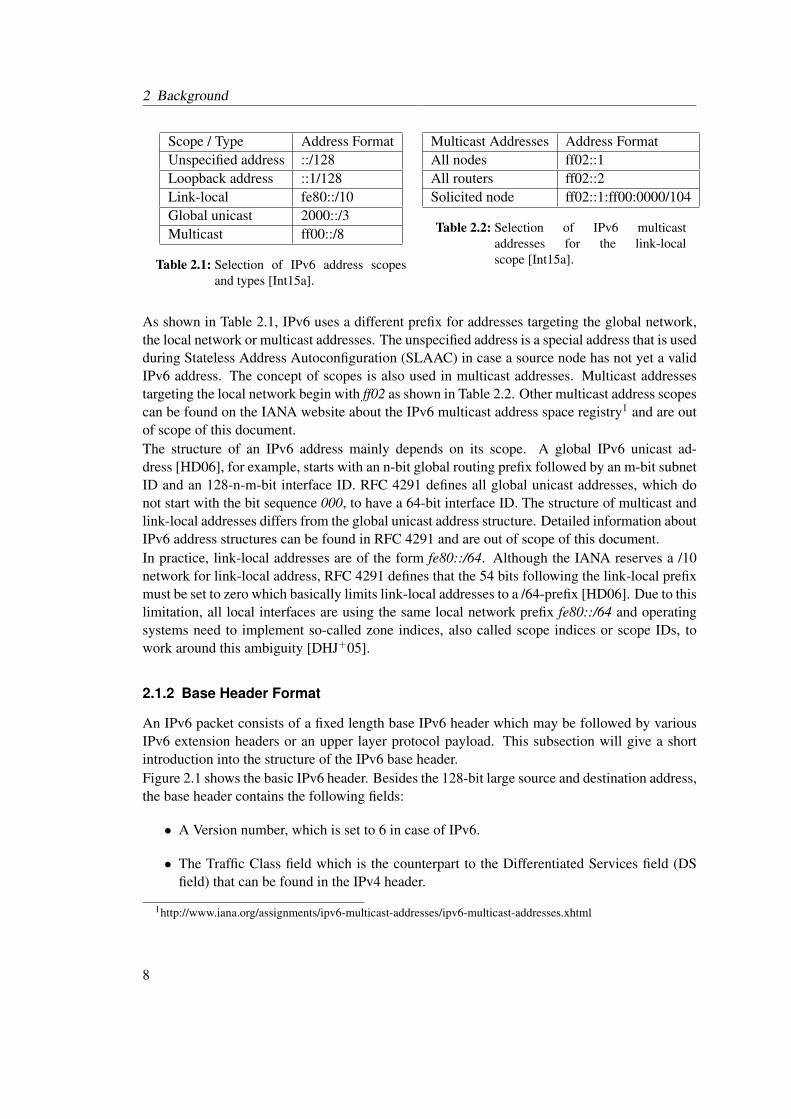
The prefix length can be used to determine the prefix and interface ID part of an IPv6 address. Asingle sequence of zeros can be stripped out so that the address of the previous example can beshortened to 2001:db8:24ab:871a::3ab/64. More details about the notation of IPv6 addressescan be found in [HD06].IPv6 introduces various address scopes and special address types that can only be used in certainuse cases. Table 2.1 lists selected types and scopes used throughout this thesis. Table 2.2 showsvarious multicast addresses which play an important role for a number of IPv6 network attacksand which are fundamental for the development of IPv6 specific honeypots.
7
2 Background
Scope / Type Address FormatUnspecified address ::/128Loopback address ::1/128Link-local fe80::/10Global unicast 2000::/3Multicast ff00::/8
Table 2.1: Selection of IPv6 address scopesand types [Int15a].
Multicast Addresses Address FormatAll nodes ff02::1All routers ff02::2Solicited node ff02::1:ff00:0000/104
Table 2.2: Selection of IPv6 multicastaddresses for the link-localscope [Int15a].
As shown in Table 2.1, IPv6 uses a different prefix for addresses targeting the global network,the local network or multicast addresses. The unspecified address is a special address that is usedduring Stateless Address Autoconfiguration (SLAAC) in case a source node has not yet a validIPv6 address. The concept of scopes is also used in multicast addresses. Multicast addressestargeting the local network begin with ff02 as shown in Table 2.2. Other multicast address scopescan be found on the IANA website about the IPv6 multicast address space registry1 and are outof scope of this document.The structure of an IPv6 address mainly depends on its scope. A global IPv6 unicast ad-dress [HD06], for example, starts with an n-bit global routing prefix followed by an m-bit subnetID and an 128-n-m-bit interface ID. RFC 4291 defines all global unicast addresses, which donot start with the bit sequence 000, to have a 64-bit interface ID. The structure of multicast andlink-local addresses differs from the global unicast address structure. Detailed information aboutIPv6 address structures can be found in RFC 4291 and are out of scope of this document.In practice, link-local addresses are of the form fe80::/64. Although the IANA reserves a /10network for link-local address, RFC 4291 defines that the 54 bits following the link-local prefixmust be set to zero which basically limits link-local addresses to a /64-prefix [HD06]. Due to thislimitation, all local interfaces are using the same local network prefix fe80::/64 and operatingsystems need to implement so-called zone indices, also called scope indices or scope IDs, towork around this ambiguity [DHJ+05].
2.1.2 Base Header Format
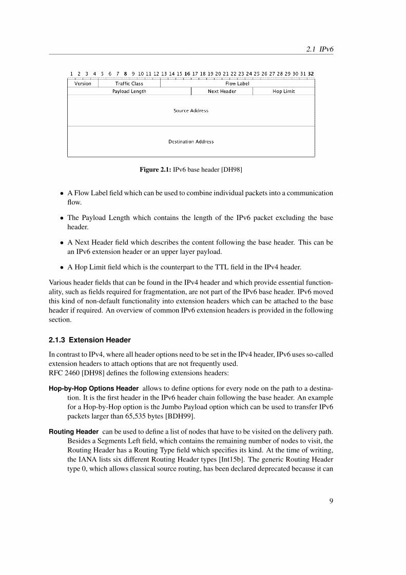
An IPv6 packet consists of a fixed length base IPv6 header which may be followed by variousIPv6 extension headers or an upper layer protocol payload. This subsection will give a shortintroduction into the structure of the IPv6 base header.Figure 2.1 shows the basic IPv6 header. Besides the 128-bit large source and destination address,the base header contains the following fields:
• A Version number, which is set to 6 in case of IPv6.
• The Traffic Class field which is the counterpart to the Differentiated Services field (DSfield) that can be found in the IPv4 header.
1http://www.iana.org/assignments/ipv6-multicast-addresses/ipv6-multicast-addresses.xhtml
8
2.1 IPv6
Figure 2.1: IPv6 base header [DH98]
• A Flow Label field which can be used to combine individual packets into a communicationflow.
• The Payload Length which contains the length of the IPv6 packet excluding the baseheader.
• A Next Header field which describes the content following the base header. This can bean IPv6 extension header or an upper layer payload.
• A Hop Limit field which is the counterpart to the TTL field in the IPv4 header.
Various header fields that can be found in the IPv4 header and which provide essential function-ality, such as fields required for fragmentation, are not part of the IPv6 base header. IPv6 movedthis kind of non-default functionality into extension headers which can be attached to the baseheader if required. An overview of common IPv6 extension headers is provided in the followingsection.
2.1.3 Extension Header
In contrast to IPv4, where all header options need to be set in the IPv4 header, IPv6 uses so-calledextension headers to attach options that are not frequently used.RFC 2460 [DH98] defines the following extensions headers:
Hop-by-Hop Options Header allows to define options for every node on the path to a destina-tion. It is the first header in the IPv6 header chain following the base header. An examplefor a Hop-by-Hop option is the Jumbo Payload option which can be used to transfer IPv6packets larger than 65,535 bytes [BDH99].
Routing Header can be used to define a list of nodes that have to be visited on the delivery path.Besides a Segments Left field, which contains the remaining number of nodes to visit, theRouting Header has a Routing Type field which specifies its kind. At the time of writing,the IANA lists six different Routing Header types [Int15b]. The generic Routing Headertype 0, which allows classical source routing, has been declared deprecated because it can
9

2 Background
be used to conduct DoS attacks [ASNN07]. An example for a commonly used RoutingHeader is Routing Header type 2. The header adds mobility support by allowing to routebetween home and care-of address of a mobile node [PJA11].
Fragment Header is used to carry information about fragmented packets. Similar to the frag-mentation mechanism in IPv4, the IPv6 fragmentation header contains a field called Iden-tification to allow the correlation of multiple fragments to a single packet as well as afragment offset to determine the fragment position.
Destination Options Header can be used to define options for the target node(s). It is the onlyIPv6 extension header that is allowed to occur more than once in the header chain, oncebefore and once after a Routing Header. At the time of writing, the IANA defines morethan 20 possible destination options. Among these is the Home Address Option whichallows to inform recipients about a node’s home address [PJA11].
Furthermore, RFC 4302 and RFC 4303 define the Authentication header and the EncapsulationSecurity Payload header respectively [Ken05a, Ken05b]. Since then, a number of further ex-tension headers, such as the Mobility Header, have been proposed but are out of scope of thisdocument.RFC 2460 does not define a consistent extension header format which may lead to many dif-ferent extension headers having a different structure. Especially for the designers of hardwarecircuits for IPv6 firewalls, this flexibility becomes a difficult issue. Therefore, RFC 6564 pro-poses to use a uniform extension header format. The proposed header format contains an 8-bitnext header field and an 8-bit value for the extension header length followed by header specificdata [KWK+12]. However, the proposed format is not backward compatible and well-knownextension headers with a different structure, such as the Fragment Header, have already beenwidely implemented.
2.1.4 IPv6 Neighbor Discovery
While IPv4 uses the Address Resolution Protocol (ARP) for the address resolution of localneighbors, IPv6 requires an entirely new protocol called Neighbor Discovery (ND) which isdescribed in RFC 4861 [NNSS07]. In contrast to ARP, the Neighbor Discovery protocol isnot limited to the sole link-layer address resolution but provides further functionalities such asrouter discovery and traffic redirection. A further distinction to ARP, which operates directly ontop of the link-layer, is that the ND protocol extends the Internet Control Message Protocol forthe Internet Protocol Version 6 (ICMPv6) and therefore requires a working IPv6 network. Thisdependency forces the ND protocol to deal with certain causality dilemmas, e.g. sending NDmessages without having a configured IPv6 address.The ND protocol was mainly developed to support the following use cases [NNSS07]: RouterDiscovery, Prefix Discovery, Parameter Discovery, Address Autoconfiguration, Address resolu-tion, Next-hop determination, Neighbor Unreachability Detection, Duplicate Address Detectionand Redirects. This section provides a limited introduction into the Address resolution as wellas into the Router and Prefix Discovery mechanisms. These mechanisms are essential for thedevelopment of IPv6 honeypots. At the same time, they belong to the most targeted mechanism
10
2.1 IPv6
when it comes to attacks on the IPv6 design. RFC 4861 further defines messages required forIPv6 Stateless Address Autoconfiguration (SLAAC) and Duplicate Address Detection which arepresented in the subsequent section. Other goals of the ND protocol are exhaustively describedin RFC 4861 and are out of scope of this document.
Resolving Link-Layer Addresses
RFC 4861 defines two ICMPv6 message types needed to resolve the link-layer address of a localneighbor: the Neighbor Solicitation and the Neighbor Advertisement message.When a node requires the link-layer address of another node in the local network then it sendsa Neighbor Solicitation message to the corresponding node. Besides ICMPv6 type, code andchecksum, the message contains the IPv6 target address for which the link-layer address is re-quested. At this point of time, the requesting node is not able to send the message directly tothe target because it is not aware of the target’s link-layer address. Instead, the node sends theNeighbor Solicitation to a so-called solicited-node multicast address. Every IPv6 node in thelocal network automatically joins a solicited-node multicast group. The solicited-node multicastaddress is created by attaching the well-known prefix ff02::1:ff00:0/104 to the last three bytes ofthe generated interface identifier [HD06].A node which receives a Neighbor Solicitation message via the solicited-node multicast addressreplies with a Neighbor Advertisement that has its link-layer address attached. The format ofa Neighbor Advertisement message is very similar to the format of a Neighbor Solicitation.Besides ICMPv6 type, code and checksum as well as the requested target address, it containsvarious flags which are out of scope of this document.
Router and Prefix Discovery
A node requires various information, such as global network prefixes and IPv6 addresses ofsurrounding routers, to communicate with other nodes outside of the local network. The IPv6ND protocol provides the two ICMPv6 message types Router Solicitation and Router Advertise-ments to gain the necessary information. Similar to the resolution of local addresses, a node cansend a Router Solicitation to the all-routers multicast address to retrieve the required informa-tion.Routers that receive a Router Solicitation reply with a Router Advertisement which carries anumber of configuration parameters. Among the parameters is the hop limit, that the nodeshould use when sending IPv6 packets, the lifetime of the router as well as timeout values forpacket retransmission and host availability. Furthermore, attached ICMPv6 options may carrythe router’s source link-layer address, the Maximum Transmission Unit (MTU) as well as therequired prefix information.
2.1.5 Stateless IPv6 Autoconfiguration
IPv6 has a built-in mechanism called Stateless Address Autoconfiguration (SLAAC) which al-lows an automatic address configuration for nodes joining an IPv6 network [TNJ07]. SLAACeliminates the need for a custom address configuration or protocols such as DHCP to make a
11
2 Background
communication possible, as it was the case in IPv4 networks. To the main functions of SLAACbelong:
• Generation of link-local addresses to enable the communication of a node in the localnetwork
• Generation of global addresses to enable Internet-wide communication of a node
A short introduction into these functions will be provided by the following subsections.
Generation of a Link-Local Address
A new node that wants to join an IPv6 network and which has SLAAC enabled first generatesa link-local address to enable the communication to other nodes in the local network. The link-local address is a combination of the link-local prefix fe80::/10 and an interface identifier whichis commonly generated based on the underlying protocol.In case of an Ethernet interface, it is common to use the Extended Unique Identifier EUI-64 asinterface identifier. The EUI-64 algorithm concatenates the first three bytes of the 48-byte longethernet address, the so-called Organizationally Unique Identifier (OUI), to the well-known bytesequence 0xFFFE and the last three bytes of the ethernet address to build a 64-byte interfaceidentifier. RFC 2491 further defines that the so-called the universal/local-bit, which is the sev-enth bit of the OUI portion, needs to be inverted to signalize whether the address is globallyor locally inverted [ASJH99]. According to RFC 2491, the inversion of the universal/local-bitmakes it easier for administrators to create custom addresses when there is no hardware tokenavailable because the bit is set to zero in this case.Before a generated link-local address can be assigned to an interface, the node must join theall-nodes multicast group as well as the solicited-node multicast group.After the node has joined the multicast groups, it runs a Duplicate Address Detection [TNJ07]to make sure that the chosen address is not already assigned to another node. The DuplicateAddress Detection works as follows: a Neighbor Solicitation message is sent to a solicitednode multicast address using the unspecified address as source address. If the node receivesa Neighbor Advertisement message within a certain timeframe then the requested address isalready taken by another node, otherwise, the node can proceed with the assignment of the localaddress. If the duplicate address detection fails than the address assignment process will becanceled in case of an address that was generated based on the link-layer. Due to the use ofthe solicited-node multicast group, a node can observe wether another node is carrying out aDuplicate Address Detection with the same address at the same time without actually being theowner of the requested address.
Generation of a Global Address
If the link-local address could be successfully generated, then a node can start the generation of aglobal address. For this purpose, the node needs to learn the prefixes that are used in the network.With the help of a Router Solicitation message that is sent to the all routers address in the localnetwork, a node can request each router in the network to reply with a Router Advertisement
12
2.2 Remote IPv6 Attacks
message. Among other information, a Router Advertisement message may contain a number ofPrefix Information options which include the prefixes maintained by a router. Using this prefixinformation, a node can assemble its global address by attaching the prefix to the previouslygenerated interface identifier.
2.1.6 IPv6 Privacy Extensions
Generating interface identifiers based on link-layer addresses, as presented in the previous sec-tion, leads to a major privacy issue. Regardless of where a node generates a global-local address,the interface identifier stays the same. This allows services which communicate with their clientsover IPv6 to keep track of their network location. RFC 4941 points out that the address corre-lation has a major privacy impacts especially when using mobile nodes, e.g. an employer couldtrack an employee’s working hours. This is a problem which does not exist in IPv4 networksbecause IPv4 addresses are not subdivided into network prefix and interface identifier. A node’sIPv4 address is entirely different in distinct IPv4 networks.IPv6 privacy extensions were originally designed to provide a mechanism that avoids the iden-tification of network cards when using IEEE based auto generated addresses [NDK07]. Theywere first described in RFC 3041 and later updated by RFC 4941.IPv6 privacy extensions provide a protocol for temporary and randomly generated IPv6 ad-dresses which avoid node tracking and which do not interfere with IPv6 Stateless Address Au-toconfiguration. The protocol presented in RFC 4941 uses one-way hash functions, such asMD5 [TC11], and random values to generate randomized interface identifiers. RFC 4941 in-cludes the history of generated interface identifiers into the hash sum generation to avoid theregeneration of the same address and to improve the randomness of an address.In some cases, a node may act as a client as well as a server at the same time. Thus, the noderequires a constant IPv6 server address. RFC 4941 proposes to use a constant IPv6 address forserver connections and multiple temporary IPv6 addresses for client connections. The temporaryIPv6 addresses have a configurable lifetime after which they should only be used for existingconnections while new connections must be initiated with a new temporary address.
2.2 Remote IPv6 Attacks
IPv6 introduces new attack vectors and inherits a number of well-known IPv4-related issues.This section presents and classifies currently known remote attacks targeting IPv6 networks.Locally applied IPv6 mechanisms, such as SLAAC, are targets of various local network attacks.This thesis, however, focuses on honeypots as an instrument to observe network attacks. Al-though it is possible to set up a honeypot to observe local network attacks, it is more commonto observe remote attacks. Therefore, this section focuses on currently known remote networksattacks so that local IPv6 attacks are out of scope of this document.Before presenting details about the selected IPv6 attacks, this section will introduce a scheme tosimplify the classification as well as the comparability of the attacks2.
2The reduced CVSSv2 vulnerability classification was developed as part of the Diploma thesis by ChristianFrieben [Fri14]. This thesis further extends this classification with attacks on the IPv6 Flow Label.
13

2 Background
2.2.1 Classification Scheme
Each IPv6 attack presented in the following sections will be classified based on the CommonVulnerability Scoring System Version 2 (CVSSv2) [MSR07]. CVSSv2 defines the three follow-ing metric groups which contain different metrics for the classification of vulnerabilities:
• Base Metrics: constant and environment independent vulnerability metrics.
• Temporal Metrics: environment independent metrics which may change over time.
• Environmental Metrics: environment specific metrics.
The classification in this document is based on a subset of the base metrics. Temporal andenvironmental metrics are not relevant in this analysis. The base metrics group contains sixdifferent metrics from which the following three are included in this IPv6 vulnerability andattack classification:
• Access Vector describes the network location from where an attacker is able to exploit avulnerability relative to the target network. The vulnerability score rises with the possibledistance from the target network required to execute an attack. Possible values are:
◦ Local: physical access to target system required.
◦ Adjacent Network: attacker needs to be located in the collision domain of the targetnetwork.
◦ Network: remote network access sufficient to exploit target system, no physical accessrequired.
• Access Complexity marks the complexity of an attack. A lower access complexity signifiesa higher vulnerability score. The access complexity can take one of the following values:
◦ High: attack requires rare system configurations or special preparations, e.g. the instal-lation of certain system privileges.
◦ Medium: requires the adversary to collect certain information before the attack cantake place. The attacker needs to belong to a certain user group or to have similarprivileges.
◦ Low: the vulnerable system can be attacked without certain permissions or insightsabout the target system, e.g. due to a fault or poor default configuration.
• Availability Impact describes the impact on the system’s availability after an attack tookplace. A large impact leads to a higher vulnerability score.
◦ None: attack has no influence on the availability of the system.
◦ Partial: system slows down or operation is partially interrupted after the attack tookplace.
◦ Complete: attack causes unavailability of the target system.
14
2.2 Remote IPv6 Attacks
Besides the CVSSv2 score and the CVSSv2 metrics Access Vector, Access Complexity andAvailability Impact, the classification contains the following custom fields to further classify anattack:
• Damage Score: describes the vulnerability level of an attack. The levels specified in this doc-ument are either adopted from existing attack evaluations or computed using the publiclyavailable CVSSv2 calculator3.
• Effect: provides a general description of the possible impact of an attack, such as denial-of-service or firewall evasion.
• Type: describes the source of an attack, such as a faulty protocol design or a wrong nodebehavior.
• Status: indicates whether the a vulnerability has been fixed.
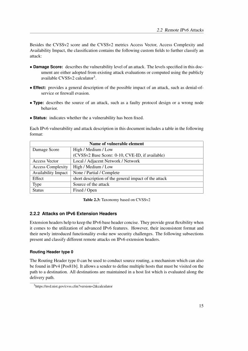
Each IPv6 vulnerability and attack description in this document includes a table in the followingformat:
Name of vulnerable elementDamage Score High / Medium / Low
(CVSSv2 Base Score: 0-10, CVE-ID, if available)Access Vector Local / Adjacent Network / NetworkAccess Complexity High / Medium / LowAvailability Impact None / Partial / CompleteEffect short description of the general impact of the attackType Source of the attackStatus Fixed / Open
Table 2.3: Taxonomy based on CVSSv2
2.2.2 Attacks on IPv6 Extension Headers
Extension headers help to keep the IPv6 base header concise. They provide great flexibility whenit comes to the utilization of advanced IPv6 features. However, their inconsistent format andtheir newly introduced functionality evoke new security challenges. The following subsectionspresent and classify different remote attacks on IPv6 extension headers.
Routing Header type 0
The Routing Header type 0 can be used to conduct source routing, a mechanism which can alsobe found in IPv4 [Pos81b]. It allows a sender to define multiple hosts that must be visited on thepath to a destination. All destinations are maintained in a host list which is evaluated along thedelivery path.
3https://nvd.nist.gov/cvss.cfm?version=2&calculator
15
2 Background
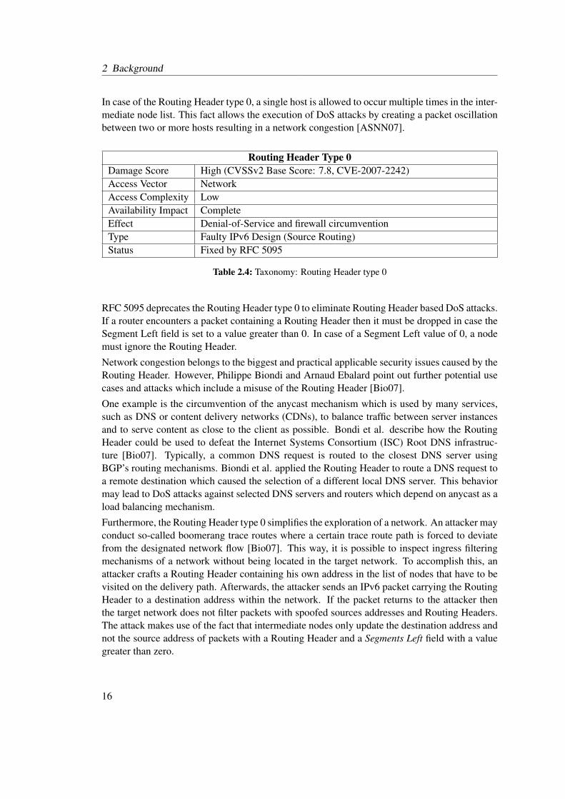
In case of the Routing Header type 0, a single host is allowed to occur multiple times in the inter-mediate node list. This fact allows the execution of DoS attacks by creating a packet oscillationbetween two or more hosts resulting in a network congestion [ASNN07].
Routing Header Type 0Damage Score High (CVSSv2 Base Score: 7.8, CVE-2007-2242)Access Vector NetworkAccess Complexity LowAvailability Impact CompleteEffect Denial-of-Service and firewall circumventionType Faulty IPv6 Design (Source Routing)Status Fixed by RFC 5095
Table 2.4: Taxonomy: Routing Header type 0
RFC 5095 deprecates the Routing Header type 0 to eliminate Routing Header based DoS attacks.If a router encounters a packet containing a Routing Header then it must be dropped in case theSegment Left field is set to a value greater than 0. In case of a Segment Left value of 0, a nodemust ignore the Routing Header.
Network congestion belongs to the biggest and practical applicable security issues caused by theRouting Header. However, Philippe Biondi and Arnaud Ebalard point out further potential usecases and attacks which include a misuse of the Routing Header [Bio07].
One example is the circumvention of the anycast mechanism which is used by many services,such as DNS or content delivery networks (CDNs), to balance traffic between server instancesand to serve content as close to the client as possible. Bondi et al. describe how the RoutingHeader could be used to defeat the Internet Systems Consortium (ISC) Root DNS infrastruc-ture [Bio07]. Typically, a common DNS request is routed to the closest DNS server usingBGP’s routing mechanisms. Biondi et al. applied the Routing Header to route a DNS request toa remote destination which caused the selection of a different local DNS server. This behaviormay lead to DoS attacks against selected DNS servers and routers which depend on anycast as aload balancing mechanism.
Furthermore, the Routing Header type 0 simplifies the exploration of a network. An attacker mayconduct so-called boomerang trace routes where a certain trace route path is forced to deviatefrom the designated network flow [Bio07]. This way, it is possible to inspect ingress filteringmechanisms of a network without being located in the target network. To accomplish this, anattacker crafts a Routing Header containing his own address in the list of nodes that have to bevisited on the delivery path. Afterwards, the attacker sends an IPv6 packet carrying the RoutingHeader to a destination address within the network. If the packet returns to the attacker thenthe target network does not filter packets with spoofed sources addresses and Routing Headers.The attack makes use of the fact that intermediate nodes only update the destination address andnot the source address of packets with a Routing Header and a Segments Left field with a valuegreater than zero.
16

2.2 Remote IPv6 Attacks
Inconsistent Extension Header Format
RFC 2460 defines that intermediate nodes on a path should not evaluate IPv6 extension headers,except for the Hop-by-Hop Options header [DH98]. However, a number of advanced existingrouters and firewalls are parsing and evaluating all existing IPv6 headers [KWK+12]. RFC 6564points out that the introduction of new IPv6 extension header types may break existing solutionsand possibly introduce new vulnerabilities. According to RFC 6564, especially the introductionof new extension headers with Hop-by-Hop behavior or new options for the existing Hop-by-Hop extension header will cause significant problems. In the future, outdated nodes may falselydrop or ignore packets containing newer and yet unknown extension headers. An attacker canexploit this situation and execute denial-of-service attacks or to create covert channels that evadefirewalls by crafting packets with unknown extension header types.
Inconsistent Extension Header FormatDamage Score Low to mediumAccess Vector NetworkAccess Complexity LowAvailability Impact CompleteEffect Denial-of-Service or evasion of firewallsType Wrong node behaviorStatus Fixed by RFC 6564 and RFC 7045
Table 2.5: Taxonomy: inconsistent extension header format
Invalid Destination Options
Each option carried by a Destination Options header has an 8-bit field which describes the optiontype. The first two most significant bits of the option type define the packet handling in case thedestination is not able to process an option. Table 2.6 lists the possible behaviors.
Bits Behavior if option cannot be processed00 If the processing of a 00 option fails, ignore the option and continue processing the
header.01 Discard the packet if option cannot be processed.10 If an 10 option cannot be processed, the packet is discarded and an ICMPv6 message
with type 4 (Parameter Problem) and code 2 (unrecognized IPv6 option encountered)has to be sent to the source address.
11 A 11 option has to be processed the same way as a 10 option with one exception:If the destination address is a multicast address, then it must not send an ICMPv6packet to the source.
Table 2.6: Processing of unknown options based on the first two most significant bits of the optiontype [DH98].
The processing rule for options with the most significant bits 10 allows an attacker to conduct
17
2 Background
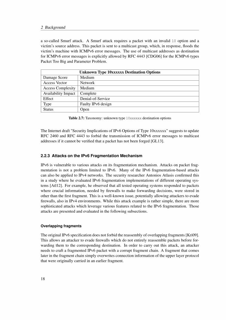
a so-called Smurf attack. A Smurf attack requires a packet with an invalid 10 option and avictim’s source address. This packet is sent to a multicast group, which, in response, floods thevictim’s machine with ICMPv6 error messages. The use of multicast addresses as destinationfor ICMPv6 error messages is explicitly allowed by RFC 4443 [CDG06] for the ICMPv6 typesPacket Too Big and Parameter Problem.
Unknown Type 10xxxxxx Destination OptionsDamage Score MediumAccess Vector NetworkAccess Complexity MediumAvailability Impact CompleteEffect Denial-of-ServiceType Faulty IPv6 designStatus Open
Table 2.7: Taxonomy: unknown type 10xxxxxx destination options
The Internet draft "Security Implications of IPv6 Options of Type 10xxxxxx" suggests to updateRFC 2460 and RFC 4443 to forbid the transmission of ICMPv6 error messages to multicastaddresses if it cannot be verified that a packet has not been forged [GL13].
2.2.3 Attacks on the IPv6 Fragmentation Mechanism
IPv6 is vulnerable to various attacks on its fragmentation mechanism. Attacks on packet frag-mentation is not a problem limited to IPv6. Many of the IPv6 fragmentation-based attackscan also be applied to IPv4 networks. The security researcher Antonios Atlasis confirmed thisin a study where he evaluated IPv6 fragmentation implementations of different operating sys-tems [Atl12]. For example, he observed that all tested operating systems responded to packetswhere crucial information, needed by firewalls to make forwarding decisions, were stored inother than the first fragment. This is a well-known issue, potentially allowing attackers to evadefirewalls, also in IPv4 environments. While this attack example is rather simple, there are moresophisticated attacks which leverage various features related to the IPv6 fragmentation. Thoseattacks are presented and evaluated in the following subsections.
Overlapping fragments
The original IPv6 specification does not forbid the reassembly of overlapping fragments [Kri09].This allows an attacker to evade firewalls which do not entirely reassemble packets before for-warding them to the corresponding destination. In order to carry out this attack, an attackerneeds to craft a fragmented IPv6 packet with a corrupt fragment chain. A fragment that comeslater in the fragment chain simply overwrites connection information of the upper layer protocolthat were originally carried in an earlier fragment.
18
2.2 Remote IPv6 Attacks
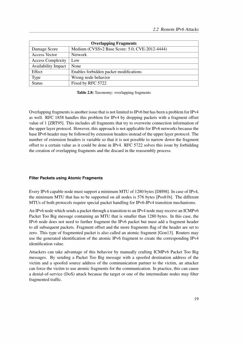
Overlapping FragmentsDamage Score Medium (CVSSv2 Base Score: 5.0, CVE-2012-4444)Access Vector NetworkAccess Complexity LowAvailability Impact NoneEffect Enables forbidden packet modificationsType Wrong node behaviorStatus Fixed by RFC 5722
Table 2.8: Taxonomy: overlapping fragments
Overlapping fragments is another issue that is not limited to IPv6 but has been a problem for IPv4as well. RFC 1858 handles this problem for IPv4 by dropping packets with a fragment offsetvalue of 1 [ZRT95]. This includes all fragments that try to overwrite connection information ofthe upper layer protocol. However, this approach is not applicable for IPv6 networks because thebase IPv6 header may be followed by extension headers instead of the upper layer protocol. Thenumber of extension headers is variable so that it is not possible to narrow down the fragmentoffset to a certain value as it could be done in IPv4. RFC 5722 solves this issue by forbiddingthe creation of overlapping fragments and the discard in the reassembly process.
Filter Packets using Atomic Fragments
Every IPv6 capable node must support a minimum MTU of 1280 bytes [DH98]. In case of IPv4,the minimum MTU that has to be supported on all nodes is 576 bytes [Pos81b]. The differentMTUs of both protocols require special packet handling for IPv6-IPv4 transition mechanisms.
An IPv6 node which sends a packet through a transition to an IPv4 node may receive an ICMPv6Packet Too Big message containing an MTU that is smaller than 1280 bytes. In this case, theIPv6 node does not need to further fragment the IPv6 packet but must add a fragment headerto all subsequent packets. Fragment offset and the more fragments flag of the header are set tozero. This type of fragmented packet is also called an atomic fragment [Gon13]. Routers mayuse the generated identification of the atomic IPv6 fragment to create the corresponding IPv4identification value.
Attackers can take advantage of this behavior by manually crafting ICMPv6 Packet Too Bigmessages. By sending a Packet Too Big message with a spoofed destination address of thevictim and a spoofed source address of the communication partner to the victim, an attackercan force the victim to use atomic fragments for the communication. In practice, this can causea denial-of-service (DoS) attack because the target or one of the intermediate nodes may filterfragmented traffic.
19

2 Background
Filter Packets using Atomic FragmentsDamage Score HighAccess Vector NetworkAccess Complexity LowAvailability Impact CompleteEffect Denial-of-Service for spoofed IP addressesType Faulty IPv6 designStatus Open
Table 2.9: Taxonomy: filter packets using atomic fragments
The network draft "Deprecating the Generation of IPv6 Atomic Fragments" attempts to depre-cate this behavior [GLA14]. If approved, the generation of atomic fragments, as described inRFC 2460, will be forbidden. Furthermore, the draft updates RFC 6145, which standardizes theStateless IP/ICMP Translation (SIIT) algorithm in a way that it does not rely on atomic IPv6fragments. The update ensures, that from the IPv6 node’s point of view, the MTU conforms atleast to the required 1280 bytes. Moreover, the update states that a Don’t Fragment flag of aresulting IPv4 packet must be cleared if a packet is less than or equal to 1280 bytes large.
Drop Packets at Destination using Atomic Fragments
This chapter presented how overlapping fragments can be used to evade firewalls. RFC 5722solves this problem by forbidding the creation of overlapping fragments and discarding them.However, this newly defined behavior opens a new attack vector. By crafting atomic fragmentsusing a spoofed IPv6 source and destination address as well as a valid fragment identification,an attacker can trigger the discard of all received packets having the selected identification.RFC 5722 defines that overlapping fragments must be silently discarded. The consequenceof this behavior combined with the atomic fragment attack is that the victim does not get anyinformation about the packet loss. This is especially a problem when the upper layer protocol isconnectionless, e.g. in case of UDP.
Drop Packets at Destination using Atomic FragmentsDamage Score Low to mediumAccess Vector NetworkAccess Complexity MediumAvailability Impact NoneEffect Packet dropsType Wrong node behavior / implementation errorStatus Fixed by RFC 6946
Table 2.10: Taxonomy: drop packets at destination using atomic fragments
RFC 6946 updates RFC 2460 and RFC 5722 and states that atomic fragments need to be ana-lyzed entirely isolated even if other fragments with the same identification are currently in thefragment queue.
20

2.2 Remote IPv6 Attacks
Oversized Header Chains
Due to its extension header concept, IPv6 has no fixed header length. Except for the headerlength field in the IPv6 base header, there is virtually no restriction regarding the number andlength of extension headers. An attacker may use this fact and inflate the header chain of a frag-mented packet in a way that important upper layer protocol information are moved to anotherfragment than the first in the header chain. This is especially a problem for stateless firewallswhich only consider the packets of a connection independently to make a routing decision. Frag-mented packets which have important upper layer protocol information in a different fragmentmay evade these kinds of firewalls.
The almost arbitrary length of the extension header chain is also a problem for stateful firewalls.These firewalls need to keep track of the extension header chain even if its distributed overmultiple fragments. By crafting a lot of large fragmented packets with an oversized headerchain, an attacker may overload a stateful firewall.
Oversized Header ChainsDamage Score High (CVSSv2 Base Score: 7.5, CVE-2006-4572)Access Vector NetworkAccess Complexity LowAvailability Impact PartialEffect Forbidden service access or denial-of-serviceType Erroneous firewall behaviorStatus Fixed by RFC 7112
Table 2.11: Taxonomy: Oversized header chains
RFC 7112 updates RFC 2460 in order to remove this attack vector [GMB14]. The update definesthat the entire IPv6 header chain must be contained within the first fragment. A node receiving apacket where the header chain is not contained in the first packet should discard the packet andreply with an ICMPv6 error message. This behavior is not restricted to the actual destinationnode but also for all intermediate nodes.
2.2.4 Attacks on the IPv6 Flow Label
The Flow Label field, which allows to assign multiple packets to a single stream, is a new field inthe IPv6 base header which has no equivalent in the IPv4 header. Although the standardizationprocess of its usage is not yet finished, it may raise security issues when widely used in thefuture. Ullrich et al. as well as RFC 6437 point out that the IPv6 flow label could be used tocarry out DoS attacks, create covert channels or to execute man-in-the-middle attacks [ACJR11,Joh14]. This section focuses on DoS attacks as well as man-in-the-middle attacks because acovert channel requires a counterpart in the local network which is out of scope of this thesis.
21

2 Background
Flow Label Flooding
A large number of different Flow Label values may exhaust the memory of a stateful firewallwhich evaluates these values. An attacker can exploit this behavior by opening many connectionswith different Flow Label values to a node on the other side of the firewall. In the worst case,the firewall is not able to process any more traffic so that the attack results in a DoS attack.
Flow Label FloodingDamage Score HighAccess Vector NetworkAccess Complexity LowAvailability Impact CompleteEffect Denial-of-ServiceType Faulty IPv6 DesignStatus Open
Table 2.12: Taxonomy: Flow Label flooding
Besides the utter disregard of the Flow Label field, there is currently no countermeasure againstthe generation of an excessive amount of Flow Label values available [Joh14].
Theft-of-Service
A forwarding node may deliberately manipulate the Flow Label field of an incoming packetto influence further load balancing mechanisms. Although this does not necessarily result ina DoS attack, it may cause a connection that performs worse than feasible. Furthermore, theintermediate node could use the privileged Flow Label value to accelerate other connections.
Flow Label Theft-of-ServiceDamage Score LowAccess Vector NetworkAccess Complexity HighAvailability Impact PartialEffect Theft-of-ServiceType Faulty IPv6 DesignStatus Open
Table 2.13: Taxonomy: Flow Label Theft-of-Service
Currently, there is no countermeasure to this attack available. However, the access complexityis comparatively high because the vicious node must be placed between source and destination.The availability impact, on the other hand, is only partial. Malicious intermediate nodes couldcause a lot more damage so that this attack is rather negligible.
22

2.3 IPv6 Network Scan Approaches
2.3 IPv6 Network Scan Approaches
Modern network scanning tools such as ZMap [DWH13] allow to scan the entire IPv4 Internetin less than 45 minutes. The huge IPv6 address space makes it practically impossible to applylinear networks scans as in IPv4 networks. Even a scan for all hosts in a relatively small IPv6network, such as a /64 network, would take years to finish. Gont et al. point out that theactual IPv6 address search space can be reduced by searching for certain IPv6 address patternsonly [GC15]. He introduces the following scan approach for IPv6 networks:
Low-byte addresses For simplification, many administrators configure so-called low-byte ad-dresses where only the last few bytes of an interface identifier are configured. Most ofthe bytes are left at zero which makes an address easy to remember. An example is theaddress 2001:db8::3. Typically a low-byte address uses only the last or last two bytes ofthe interface identifier which reduces the search space to 216 addresses.
Embedded IPv4 addresses Especially in dual-stack environments, where a device has an IPv4as well as an IPv6 address assigned to it, administrators tend to configure the last few bytesof an IPv6 address with the corresponding IPv4 address. For example, a device havingthe IPv4 address 93.184.216.34 gets the IPv6 address 2001:db8::93.184.216.34 assigned.Hence, an attacker only needs to search through the IPv4 address space if the IPv6 prefixis known. If the IPv4 subnet is known, the search space can be further reduced.
Embedded port Similar to embedded IPv4 addresses, it is common to embed the port of aservice running on the IPv6 host into the IPv6 address. For example, a web server listeningon port 80 may have the address 2001:db8::80. This reduces the applied address space tothe number of well-known ports.
Wordy addresses The hexadecimal IPv6 notation allows to embed a number of words into anaddress, e.g. 2001:db8::cafe. A dictionary-based network scan can leverage this possibil-ity and quickly find those hosts.
Addressees configured with SLAAC If stateless address auto configuration with embeddedIEEE identifiers is used and the network prefix is known, then a scan can reduce thesearch space by only testing combinations that contain valid Ethernet addresses.
Transitions IPv6 to IPv4 transition mechanisms usually utilize certain address patterns. TheISATAP mechanism, for example, includes 0000:5EFE between prefix and the host’s IPv4address [TGT08]. Again, this reduces the search space to the number of possible IPv4addresses.
DNS If administrators added DNS entries for their IPv6 hosts, these hosts could be found byrequesting common domain names from DNS servers or by leveraging reverse DNS map-pings. Of course, this approach cannot be observed in a darknet.
Publicly available IPv6 network scanners, such as scan6 [SI612], bundle these scanning ap-proaches into easy-to-use tools. It is therefore reasonable to expect the listed approaches whenobserving IPv6 traffic.
23
2 Background
2.4 Darknets
An important condition for the development of network security tools is an understanding ofthe expected network traffic and the services that are focused by potential attacks. Metrics suchas traffic rate, requested services or scanning patterns help to customize network tools so thatthey can properly handle their specific use cases. One approach to collect the required pieces ofinformation about a network is the utilization of so-called darknets. A darknet is a system whichmonitors the activity in an unused address space [BCJ+06]. In contrast to intrusion detectionsystems (IDSs), darknets do not interact with an attacker but only passively monitor their activity.Although their capabilities are very limited, darknets provide a valuable tool when it comes tothe basic evaluation of network traffic and the resulting threat level of a network.In contrast to many other network appliances, such as firewalls or IDSs, there is no specificinstruction of how to set up a darknet. Besides an unused address space, the installation of adarknet requires a component which captures network traffic. Darknet experiments presentedin this thesis make use of machines running the packet analyzer tool tcpdump [Tcp15]. Thecaptured traffic can either be analyzed manually or with the help of various traffic analysis tools.Because there is still a lack of IPv6-specific traffic analysis tools, a number of scripts weredeveloped within the scope of this thesis to automate the analysis of IPv6 darknet traffic.
2.5 Honeypots
Passive network traffic monitoring, as conducted by darknets, is not sufficient if an extensiveanalysis of attacks to upper layer network services is required. In a darknet environment, anattacker typically aborts an attack to a specific service because of the lack of interaction. Theseuse cases require more sophisticated security appliances such as so-called honeypots.As pointed out in the introduction of this thesis, honeypots are very different from most tradi-tional security mechanisms. The only purpose of a honeypot is to get attacked so that informa-tion about an attack’s purpose or procedure can be gathered [Spi02]. A honeypot system hasno production value and is commonly configured to monitor an unused address space. Hence,every communication with the honeypot can be considered potentially hostile. A honeypot canbe something like a computer or even a mobile phone which is set up to attract attackers. Byusing various monitoring mechanisms, honeypots can provide valuable data about an attack andthe strategies used by the attacker. This information can later be used to develop appropriatecountermeasures.IDSs, such as Snort [BBEN07], passively observe the network communication between multiplehosts and send alarms if they detect patterns that indicate malicious activities. Honeypots, on theother hand, interact directly with an adversary and therefore have a lot more control and insightinto the communication. This property of honeypots even allows an end-to-end communicationto an attacker through encrypted channels, which could not be accomplished using a darknet oran IDS.Some scenarios, such as the observation of worm propagations, require the installation of com-plex honeypot networks. Such a network of honeypots is also called a honeynet [MFHM15].Honeypots are typically classified based on their level of interaction. Although other classifica-
24
2.5 Honeypots
tions and classes exist, the following three classes of honeypots are most commonly used withinpublications and throughout this thesis:
High-interaction honeypots are real or virtual machines running genuine services [GJJ+12].They provide an authentic environment, usually extended with various hidden loggingmechanisms, which can be attacked. This way, high-interaction honeypots allow a com-prehensive analysis of attacks even to sophisticated and complicated network services. Acompromised high-interaction honeypot may be used by an attacker to conduct furtherattacks to other machines [MFHM15]. This potential security threat needs to be consid-ered and, depending on the use case, perhaps prevented when deploying high-interactionhoneypots.
Low-interaction honeypots simulate services instead of providing genuine and authentic net-work services [GJJ+12]. This approach usually requires less performance and providescertain control and logging mechanisms which are not implemented in the real service.However, many low-interaction honeypots only provide a subset of service capabilitiesand the simulation granularity differs between different low-interaction honeypot imple-mentations. A major advantage over high-interaction honeypots is that an attacker is notable to carry out further attacks after compromising a low-interaction honeypot becausethe honeypot has a lot more control over possible actions. Low-interaction honeypotscan further be subdivided into single-purpose and general-purpose honeypots. A single-purpose honeypot is specialized in the simulation of one specific service while general-purpose honeypots are able to simulate a variety of network services.
Hybrid honeypots are a combination of both, low- and high-interaction honeypots [GJJ+12].Hybrid honeypot architectures try to pool the advantages of both honeypot interaction lev-els while eliminating their disadvantages. A common approach is to process sophisticatedattacks with the help of high-interaction honeypots while forwarding network scans or lesscomplex attacks to low-interaction honeypots. However, the traffic distribution betweenlow- and high-interaction honeypots differs from project to project.
Honeyfarms maintain a collection of honeypots [VMC+05]. The term usually refers to large-scale honeypot projects which deploy hundreds or even thousands of honeypots. A honey-farm can be installed, for example, in data centers or cloud infrastructures which providethe required hardware infrastructure.
A comprehensive classification and evaluation of different honeypot implementations can befound in a honeypot study published by the European Network and Information Security Agency(ENISA) [GJJ+12]. The next chapter presents a selection of major honeypot projects whichutilize various concepts valuable for the development of IPv6-specific honeypots.
25

2 Background
26
3 Related Work
The last chapter introduced the fundamental theoretical background required for this thesis, in-cluding the concepts of darknets and honeypots. This chapter begins with a presentation ofmajor IPv6 darknet experiments and summarizes their results. Subsequently, considerable hon-eypot projects are presented and their capabilities, in respect of their eligibility for the use inIPv6 networks, evaluated. The different honeypot projects are divided into several subsections,depending on their level of interaction.
3.1 Prior IPv6 Darknet Experiments
This section presents the results of selected IPv6 darknet experiments, ordered by their publi-cation title. Network sizes, the technique used to monitor the networks and the duration varyamong the different experiments which leads to very different observations. Therefore, thissection summarizes common conclusions after presenting the individual experiments.
Initial Results from an IPv6 Darknet
In 2006, Matthew Ford et al. published a traffic statistic of their IPv6 darknet with a /48 prefix,which may have been the world’s first IPv6 darknet [FSR06]. Within approximately 16 months,they captured about 12 ICMPv6 packets which were most probably caused by misconfigurationand typographical errors resulting from the long and unwieldy IPv6 addresses. In comparison,Pang et al. observed in 2004 about 30,000 packets of background radiation per second in a classA IPv4 network [PYB+04].
Background Radiation in IPv6
In 2010, Geoff Huston presented the results of a darknet experiment where he examined thebackground radiation in a 2400::/12 network provided by APNIC [Hus10]. Within 9 days, thedarknet received about 21,000 packets. It is assumed that the received traffic is caused by mis-configuration and probably a small number of guess probes. Scans that are definitely producedby bots or viruses could not be detected. In contrast to classical darknet experiments, the used/12 address block was not vacant. About 1.6 percent of the network addresses had already beenallocated. Even though traffic targeting the allocated address space was filtered before furtheranalysis, it is difficuilt to compare the results of this experiment to other darknet results.
27
3 Related Work
Understanding IPv6 Internet Background Radiation
Czyz et al. conducted one of the largest publicly documented IPv6 traffic observations, in-cluding five /12 networks from five different Regional Internet Registries (RIRs) [CLM+13].In contrast to classical darknet experiments, where an unused address space is under observa-tion, the authors used a so-called covering prefix methodology. The observed address space isnot completely unused but partially occupied by customers of the corresponding RIRs. BorderGateway Protocol (BGP) update messages were used to announce routes for the entire /12 net-works. The methodology leverages the fact that if there is no more specific route for a destinationavailable, in this case announced by an RIR customer, then the traffic is routed to a collectionserver which captures the network traffic. In some cases, the used methodology caused routingproblems and led to a number of discussions. For example, RIPE received multiple customercomplains because of BGP validation issues caused by the experiment1. A major problem of thisapproach is that if a route is temporary unavailable on a BGP router or if a prefix owner does notannounce a route intentionally, then the traffic is also forwarded to the collection server. There-fore, customers may experience routing failures and traffic captured with the covering prefixmethodology may contain actual production traffic. Eventually, RIPE replaced their provided/12 prefix with an unallocated /13 and /14 prefix.The covering prefix methodology has the advantage that it is able to cover large network spacesaround production networks. The authors show that the number of captured packets is muchhigher than the amount of traffic that would have been observed with classical network tele-scopes. Furthermore, it is easier to find routing instabilities and misconfigurations and allowsthe observation of traffic close to production networks.The authors presented statistics for two datasets of captured traffic, one dataset containing a24 hour traffic capture and a three months capture dataset. The captured packets were segre-gated into the categories unallocated/unrouted, unallocated/routed, allocated/unrouted and allo-cated/routed. In both datasets, the allocated traffic included about 95% of the total amount oftraffic. About 5% of the traffic belonged to an unallocated prefix.The 24-hour-dataset contained about 42% UDP, 20% TCP and 38% ICMPv6 traffic. Accordingto the authors, the huge amount of UDP traffic was caused by misconfigured DNS servers. Incase of the 3-month-dataset, TCP was the most occurring packet type with about 45%, followedby UDP with about 31% and ICMPv6 with about 23%. Before filtering the captured traffic, itcontained about 34% transition traffic, send from sources belonging to Teredo [Hui06] or similarIPv6 transition mechanisms.The presented results show that few IPv6 sources are responsible for most of the captured IPv6traffic and that most traffic is targeted at a small number of destinations. In case of the unallo-cated and unrouted traffic in the 3-months-capture, a single source address was responsible forabout 35% of the entire ARIN traffic. Furthermore, more than 30% of the packets in the APNICcapture were targeting a single destination.The authors could not find any evidence of malicious activity in the IPv6 networks, like large-scale networks scans or distributed DoS attacks. However, the traffic indicates network mis-configurations in various cases. This stands in contrast to their one-week IPv4 capture that was
1https://labs.ripe.net/Members/mirjam/ipv6-darknet-experiment/view
28

3.2 Low-interaction Honeypots
created in parallel to the IPv6 experiment and which shows active network probing and a hightraffic pollution.
Summary
All published IPv6 darknet results indicate that IPv6 networks are mostly free of threats. Noneof the observations show malicious activity or large-scale network scans. The first IPv6 darknetexperiment, conducted in 2006, captured a negligible number of unintentional transmitted pack-ets. Latest results indicate that IPv6 is actively being used, although the traffic captured in thescope of the darknet experiments was most probably caused by misconfiguration. The amount oftraffic that was captured in all IPv6 darknet experiments is still very low compared to the trafficthat can be found in IPv4 networks.
3.2 Low-interaction Honeypots
Low-interaction honeypots allow the observation of attacks without installing a complex net-work infrastructure. A recent study about different honeypots, published by the European Net-work and Information Security Agency, lists seven different low-interaction, general-purposehoneypots [GJJ+12]. Within the scope of this thesis, two of the honeypots projects were consid-ered for a use in IPv6 networks: Honeyd [Pro04], because it provides great flexibility throughthe use of a customized network stack, and Dionaea [Dio14], because it is the only project whichwas classified to be very useful in the ENISA study. Both honeypot projects are introduced inthe following subsections.
Honeyd
Honeyd is a low-interaction honeypot which has been developed by Niels Provos in the C pro-gramming language and is currently available in version 1.5c on the project website2.Honeyd provides a framework that enables users to write service scripts for Honeyd’s virtualhosts, e.g. a script that simulates a telnet service and captures all log-in attempts of an attacker.These service scripts can be bound to IPv4 addresses which are managed by Honeyd.Honeyd supports the simulation of entire IPv4 networks which is accomplished by a customizednetwork stack implementation using the network capture library libpcap [Tcp15] to bypass thehost’s stack implementation.Honeyd does not implement an IPv6 stack and can only simulate IPv4 networks. Within thescope of this thesis, Honeyd was chosen to be extended for the use in IPv6 networks. Chapter 4describes the IPv6 implementation process and explains the internal functioning of Honeyd.
Dionaea
Dionaea is a low-interaction honeypot which provides several exploitable weaknesses for differ-ent protocols, such as SIP [RSC+02], HTTP [FGM+99] or FTP [PR85]. Its main focus lies on
2http://www.honeyd.org/
29
3 Related Work
attacks to the Server Message Block (SMB) protocol. Dionaea provides the ability to automati-cally detect and extract shellcode attacks through the libemu shellcode detection library [Pau14].Malware, downloaded by an attacker, can automatically be stored for later analysis. The honey-pot stores events in a SQLite database so that SQL queries can be used to evaluate attacks.Dionaea has built-in IPv6 support. However, in contrast to Honeyd, Dionaea connects to anattacker via sockets of the underlying operating system and is therefore not able to simulateentire networks.
3.3 High-interaction Honeypots
The ENISA honeypot study evaluated five different high-interaction honeypot projects. Two ofthe projects, the high-interaction honeypots Argos [PSB06] and HIHAT [MFHM15], are rateduseful [GJJ+12]. The following subsections provide an overview of the basic functioning ofthese two projects. The ENISA considered HIHAT as a single high-interaction honeypot projectalthough the report refers to the aggregated functionality of multiple tools, called Honeypot-Creator and HIHAT. This sections describes the capabilities of these sub-projects individuallybut in a single subsection. All other projects were classified not to be useful and are out of scopeof this thesis.
Argos
Argos is a high-interaction honeypot which is based on the open-source machine emulatorQEMU [Bel05]. The project utilizes a modified x86 processor which allows the monitoringof all CPU instructions. Argos allows the deployment of all x86-compatible high-interactionhoneypot operating systems, such as Linux or Windows, without any modification.In order to automatically detect network attacks, Argos employs a methodology called taintchecking. Data that comes from a potential attacker through the emulated network interface ismarked as tainted. Argos monitors the flow of tainted data and rises an alarm when the databecomes a part of a CPU instruction. This is the case, for example, when a tainted value isstored in the x86 EIP register, which is responsible for holding the instruction pointer. In caseof an alarm, the tainted memory blocks are dumped into a file for later analysis.Some information about an attack, such as process identifier or open files, are normally notaccessible from outside of a virtual machine. Argos works around this limitation by injectingcustom shellcode into the virtual address space of the process to retrieve the missing information.This mechanism, however, requires a separate process running on the guest operating systemwhich sends the extracted information to the host operating system. Currently, the extractionmechanism is only available for Linux and Windows systems.
Honeypot-Creator and HIHAT
Honeypot-Creator is a system, which can automatically convert PHP-based web applicationsinto high-interaction honeypots. HIHAT allows the automatic analysis of high-interaction hon-eypot data collected with Honeypot-Creator [MFHM15]. Although the ENISA rates both projects
30
3.4 Hybrid Honeypots
under the name HIHAT, this section presents both sub-projects individually.Honeypot-Creator takes a PHP-based web application as an input and recursively searches forall PHP and HTML files of the application. The system adds additional logging statements to thebegin of each file in the search result. The logging statements evaluate the global PHP variables$_SERVER, $_GET, $_POST and $_COOKIE which store valuable information about all requests aswell as the server configuration. All logged data is persisted into a SQL database running on anexternal logging server.Logging statements, created by a high-interaction honeypot that was created with the Honeypot-Creator, can be evaluated with the analysis tool HIHAT. HIHAT provides an interface whichhelps the honeypot provider to quickly overview logged events and find specific attacks. It isnot a fully automated log analyzer and requires human interaction. With the help of regularexpressions, HIHAT is able to automatically filter predefined attack patterns. The operator canfilter the events based on various criteria, such as date or time. Files, which an attacker triesto download within an attack, can automatically be downloaded for a later analysis. A furtherfeature of HIHAT is the automatic determination of an attacker’s position based on the sourceIP address.
3.4 Hybrid Honeypots
Hybrid honeypots combine low- and high-interaction honeypots in order to avert the disadvan-tages of both honeypot types while combining their advantages. The combination of differenthoneypot types requires complex architectural concepts. Different hybrid honeypot projects andtheir approaches to incorporate low- and high-interaction honeypots are described in this section.
A Hybrid Honeypot Architecture for Scalable Network Monitoring
Bailey et al. presented one of the first hybrid honeypot architectures which utilizes low- andhigh-interaction honeypots and which focuses on observations of worm propagations [BCW+04].Low-interaction honeypots are located directly in a target network, such as in a university orcorporation network, and process known and uninteresting traffic. Interesting traffic, caused byunknown attacks, is forwarded from the low-interaction honeypots to a central backend whichcontains multiple high-interaction honeypots as well as a control monitor. The control monitoris able to regulate the low-interaction honeypot behavior and balances the incoming traffic overa fixed number of high-interaction honeypots under a certain load.A novel approach detects new kind of attacks and decides when to hand-off traffic to high-interaction honeypots. Prevalence filters, located in the low-interaction honeypot layer, evaluatethe first bytes of a connection and try to detect new type of attacks. When encountering a novelattack, that is if a traffic flow deviates all previously observed flows, the low-interaction honeypothands-off the connection to a high-interaction honeypot. The hand-off requires the replay of thethree-way TCP handshake and the subsequent traffic to an available high-interaction honeypot.The presented prevalence filter is limited to the observation of the first packets of each traffic flowonly. Because an attack may differ from previous attacks later on, the architecture implements asampling support which periodically forwards known attacks to a high-interaction honeypot.
31
3 Related Work
The utilization of a fixed number of high-interaction honeypots causes a number of architecturallimitations. First, IP addresses of these honeypots stay unchanged which may quickly revealthe honeypot infrastructure. Second, multiple attacks may be forwarded to the same honeypotinstances which aggravates a forensic analysis. The monitoring capabilities of the architectureare limited to the observation of the network communication at the low- and high-interactionhoneypots. The authors make no statements about how to manage fatal high-interaction honey-pot system errors or how to analyze any high-interaction honeypot internals, such as hard diskor memory.In a study with three low-interaction honeypot sensors, the authors found out that most of thepackets belong to previously observed attacks and that it is sufficient to only observe about 0.25percent of the traffic to find novel attacks. Even though all three sensors mostly observed thesame kind of traffic within this study, the authors point out that it is important to deploy multiplesensors in order to monitor worm propagation.The presented architecture has not been completely implemented so that further performancetests were left for future work.
GQ
Cui et al. presented a hybrid honeypot system which utilizes a machine learning approach forthe processing of network attacks [CPW06].Incoming traffic first arrives, through GRE tunnels or directly through network telescopes, ata GQ Controller. The GQ controller implements various filter mechanisms and connects at-tackers to high-interaction honeypots running on an VMware ESX host. Besides a first packetsfilter, which can also be found in the architecture presented by Bailey et al., the GQ Controllercontains a protocol learning network proxy component which is located between attacker andhigh-interaction honeypot. The proxy component, which is based on the replay system Role-Player [CPWK06], observes the communication with the attacker and learns new and unknownprotocol flows. As long as the proxy is able to replay a previously observed and potentiallyslightly modified network flow, it directly answers to the attacker without any further commu-nication to a high-interaction honeypot. As soon as a protocol deviation is observed, the proxyreplays the communication as client to a high-interaction honeypot until the deviation point isreached. From then on, the proxy forwards traffic coming from the attacker directly to the high-interaction honeypot and learns the protocol behavior.The usage of Role Player as protocol replay system limits the honeypot architecture to protocolswhich do not use encryption [CPWK06]. Hence, attacks which require SSH or HTTPS to workcan not be monitored with this architecture.One of the main goals of the presented system is a high scalability. To achieve this, the GQController implements a number of traffic filtering techniques to reduce the load on the high-interaction honeypots.The high-interaction honeypots are separated from each other by using virtual local area net-works (VLANs) and network address translation (NAT) is used to map the IP address expectedby an attacker to the actual IP address of the honeypot. A major limitation of the NAT-based IPassignment approach is that the honeypot address differs from the attacker’s target address which
32
3.4 Hybrid Honeypots
may quickly reveal the honeypot. Outgoing traffic of a high-interaction honeypot is filtered orforwarded based on certain policies which include various traffic attributes, such as source ad-dress or traffic rate. Potential malicious traffic is routed back into the honeynet to a new availablehoneypot.
Honeybrid
In [Ber09], the author presents the hybrid honeypot architecture called Honeybrid which formsa skeleton for honeypot solutions with focus on scaleability. Similar to most hybrid honeypotarchitectures, Honeybrid comprises low- and high-interaction honeypots as well as a networkgateway. Incoming network traffic first arrives at the gateway, which, by default, forwards thetraffic to low-interaction honeypots. The gateway includes a so-called Decision Engine, whichfilters uninteresting traffic to reduce the load on the honeypots. A second component of thegateway is a Redirection Engine which redirects traffic to high-interaction honeypots if it isdetected as interesting by the Decision Engine.Honeybrid is rather a framework than a fully implemented honeypot architecture. It allows toimplement custom honeypot solutions according to individual research goals. The DecisionEngine is written in a modular style which allows to implement and combine several decisionfilters. The author presents an example where payloads of incoming connections are matchedagainst a database of previously observed payloads in order to identify new kind of attacks.The Redirection Engine of Honeybrid forwards interesting connections to high-interaction hon-eypots. It replaces the IP addresses in the original network traffic and initializes the requiredTCP or UDP connection on the high-interaction honeypots. Because the proposed architectureforwards connections after they have started to exchange payload, protocols that use encryption,such as SSH or HTTPS, are not supported. A further limitation of the architecture is that IPaddresses on the high-interaction honeypots do not match the address expected by an attackerwhich may uncover the honeypot architecture.Honeybrid is flexible in terms of the applied honeypot solutions. An evaluation, provided by theauthor uses QEMU-based virtual machines as high-interaction honeypots and Honeyd [Pro04]to implement the low-interaction honeypot side. This setup is limited to IPv4 networks. Theauthor does not provide any information about whether the architecture can be applied to IPv6capable honeypots.
VMI-Honeymon
Lengyel et al. [LNM+12] introduced the Perl-based high-interaction honeypot monitor VMI-Honeymon and a corresponding integration into a hybrid honeypot architecture based on Hon-eybrid [Ber09]. The presented system detects anomalies in a virtual machine based high-interaction honeypot by frequently analyzing the virtual machine’s memory. The authors de-cided to use Xen for the machine virtualization after facing stability issues with KVM.Xen provides a library called LibVMI [Paynd] for virtual machine introspection. A Volatil-ity [Vol15] extension that uses the LibVMI API is used to find files which were newly createdby attackers in the main memory of a high-interaction honeypot. In order to take the load offthe high-interaction honeypots and to ensure that only one attacker is attacking one honeypot at
33
3 Related Work
a time, VMI-Honeymon adds Dionaea [Dio14] to the low-interaction honeypot layer of Honey-brid [Ber09].Furthermore, the authors implemented a custom Honeybrid Decision Engine module which sup-ports a communication between Honeybrid and Dionaea. Previously observed IP addresses,which attacked Dionaea and left a payload, are automatically filtered by Honeybrid. OutgoingDNS requests are forwarded to DNS chef [DNS14], which is as special DNS proxy designedfor penetration testing. It provides detailed logging information about incoming DNS requestsso that it is possible to identify communication endpoints of an attack. Outgoing traffic is fil-tered and a honeypot is allowed to communicate back to an attacker only in order to avoid theinfection of further hosts.An attacker is redirected from a high-interaction honeypot back to a low-interaction honeypotafter 10 minutes of stalled communication. VMI-Honeymon then executes the Volatility analysisfor the high-interaction honeypot and parses the results. If an attacker placed a new binary onthe high-interaction honeypot then this binary is uploaded to the online virus scanning serviceVirusTotal3.The authors tested the prototype implementation of VMI-Honeymon with high-interaction hon-eypots running Windows XP SP2. In order to simplify the memory analyzes, the Windows XPconfiguration was slightly modified. Automatic system updates and processes, such as screen-saver, were disabled and no additional software was installed. Hence, the high-interaction hon-eypots listened for network requests on the default ports 135, 139 and 445 only. Because theproposed system is an extension of Honeybrid, it has the same limitations, such as the missingsupport of encrypted protocols.
Honey@home
Antonatos et al. present a hybrid honeypot architecture, called Honey@home, which focuses onlarge-scale network monitoring [AAM07]. The architecture was developed within the scope ofan EU research project called NoAH [Koh09], running from 2005 to 2008.Honey@home allows interested third parties to participate in the architecture by installing aspecial client which forwards traffic of an unused IP address space or unused ports to a centrallocation which processes the traffic. The Honey@home client installs a pseudo-interface on thehost machine and either requests a new IP address via DHCP or uses a statically configured IPaddress to start the monitoring process.The central core of the architecture contains the low-interaction honeypot Honeyd [Pro04] aswell as a set of the high-interaction honeypot Argos [PSB06]. Honeyd is used to process un-interesting traffic, such as network scans. Connections which are considered interesting, forexample if they finish the initial TCP handshake, are forwarded to an Argos instance. The se-lection of the Argos instance is based on the destination port of the incoming connection. Forexample, a connection which targets a classical Windows service is forwarded to an Argos in-stance that runs a Windows operating system. To achieve this, the authors implemented theability to hand-off a connection from low- to high-interaction honeypot into Honeyd. However,the they do not provide any information about how the hand-off mechanism works.
3https://www.virustotal.com
34
3.4 Hybrid Honeypots
In order to hide the actual honeypot addresses and to protect the identity of the participants, theanonymity network TOR4 is used. TOR implements onion routing which encrypts a messagemultiple times for different onion routers on a path to hide a users identity [AAM07].The static set of high-interaction honeypots and the connection via TOR has a number of lim-itations which were not discussed by the authors. Multiple attackers may be forwarded to thesame high-interaction honeypot. It is not clear how the system reacts in case an attacker suc-cessfully compromises or even shuts down a high-interaction honeypot. Furthermore, althoughTOR makes sure that an IP address remains hidden on the network layer, it does not concealan address on the application layer. For example, an attacker which successfully establishes aconnection to a high-interaction honeypot via SSH may quickly discover the real IP address ofthe honeypot.Honey@home does not support IPv6 networks, primarily due to the use of Honeyd for the low-interaction honeypot layer. Honeyd implements a customized IPv4 network stack which doesnot support IPv6.In [AAM07], the authors make contradictory statements about whether a Honey@home clientcan be used to observe larger address space chunks. A Honey@home client is described tobe responsible for the monitoring of a single IP address. However, the authors also state thata Backus-Naur Form-based configuration expressions can be used to monitor multiple IP ad-dresses with a single client.
A hybrid System for Wireless Mesh Networks
In [RGAS12], the authors present a hybrid honeypot architecture for wireless mesh networks.In contrast to traditional wireless networks, wireless mesh networks do not depend on a fewavailable access points to establish a connection to the Internet. Devices in a mesh network mayshare an Internet connection so that a connection can be established via other devices in thenetwork which are directly or indirectly connected to the Internet. Wireless mesh networks areself organizing and can rapidly grow through the addition of further participants which are hardto control. The presented honeypot system is designed to help analyzing attacks within thesenetworks.The proposed architectures divides a wireless mesh network into multiple clusters, each con-sisting of low-interaction and high-interaction honeypots. The low-interaction honeypots handleport scans, generate attack signatures and collect malware samples within their cluster. If anattack is detected, then the connection is handed over to a high-interaction honeypot which runsvarious malware detection and analysis tools. The result logs of an analysis are sent to a centralrepository which formats and stores them in a unified format in a database.The authors suggest to request a unique identification, such as a social security number, whenaccessing the mesh network. This identification is used by the architecture to automaticallyexpel malicious users, e.g. users that executed an attack.The authors propose to use the low-interaction honeypot Honeyd although it does not fulfillall architectural requirements. The presented architecture expects a malware detection enginein the low-interaction honeypot layer because traffic is only forwarded to a high-interaction
4https://www.torproject.org
35

3 Related Work
honeypot if it detects malware in this layer. However, the official version of Honeyd does notprovide a malware detection engine. Similar to other projects which are based on Honeyd,the proposed architecture cannot be used in IPv6 networks due to the missing IPv6 support ofHoneyd. Because there is no implementation of the proposed architecture available, it is notpossible to provide any further evaluation.
3.5 Large-scale Honeyfarms
The honeypot projects presented in the previous sections apply and combine different interac-tion levels to provide preferably authentic services or best possible performances. This sectionpresents honeypot projects which focus on the provisioning of a large number of honeypot in-stances, also called honeyfarms. Although all of the following projects implement various mech-anisms to increase their system performance, the main focus lies on the supply of a large numberof machines. Large-scale honeyfarms, as presented in this section, require multiple servers, datacenters or even cloud-based infrastructures.
Collapsar
One of the first presented honeyfarm architectures is Collapsar [JD04]. Similar to the Honey@home architecture [AAM07], Collapsar was designed in a distributed manner, which allows thirdparties, such as businesses or universities, to provide their address space for the monitoring ofattacks. Collapsar requires the installation of so-called redirectors, which tunnel connections tounused IP addresses to a gateway that is connected to a so-called Collapsar Center. The Collap-sar Center contains virtual machine-based high-interaction honeypots, a honeypot managementstation as well as a correlation engine. A gateway transparently distributes incoming packets tothe corresponding honeypots and filters unwanted traffic. From an attacker’s point of view, thehoneypots seem to be located in the production network which contains the redirector.The honeypots are running on VMware and User Mode Linux (UML) virtual machines. Thetransparent tunneling mechanism from redirector to the actual honeypot requires changes to thenetwork interface implementation of the virtualization software. The packets tunneled to thegateway are directly injected into the network interface controller (NIC) implementation of thehoneypot. The server-side honeypots have different operating systems installed running variousnetwork services, for example, Linux machines running Apache httpd or Windows XP machinesrunning RPC system services.Collapsar applies different internal and external logging mechanisms. The packet analyzer tooltcpdump [Tcp15] is used to capture raw traffic between attacker and honeypot. The VMware-based honeypots use the logging module Sebek [The15a] and the UML machines use the loggingmodule kernort [JXE04] to log internal system events.Collapsar also provides client-side honeypots. In contrast to the server-side honeypots, Col-lapsar’s client-side honeypots actively connect to malicious web servers using different clientsoftware to detect new malware. Client-side honeypots are out of scope of this dissertation andwill not be presented in more detail.
36
3.5 Large-scale Honeyfarms
Collapsar’s redirectors implement ARP spoofing to acquire IP addresses which limits the pro-posed architecture to IPv4 networks. The authors do not provide any information about whetherCollapsar will support IPv6 networks in the future.
Potemkin
In [VMC+05], the authors present the Potemkin honeyfarm system which is able to dynamicallycreate thousands of virtual machine-based high-interaction honeypots on-demand.Potemkin implements a special gateway which is connected to the Internet and which dispatchesincoming requests to internal honeyfarm servers running Xen virtualization software. Based onthe IP addresses of these incoming requests, a virtual machine monitor uses two techniquescalled flash cloning and delta virtualization to rapidly instantiate new high-interaction honey-pots.flash cloning creates a copy of an already booted virtual machine reference image for each newvirtual machine to avert a time consuming startup phase. Delta virtualization allows to transferthe corresponding memory contents of the reference machine on-demand to the newly instanti-ated and already running honeypot instance. The presented implementation of the delta virtu-alization leverages Xen’s shadow memory table mechanism. A Xen guest operating system hasno direct access to the physical memory of the host machine. Instead, Xen inserts a further layerwhich represents the physical memory of the guest machine and which is located between theguest’s virtual address space and the physical machine memory of the host machine. Potemkin’smachine cloning mechanism shares the physical address between multiple virtual machine in-stances. This works by referencing the same physical host memory location in multiple shadowtables for different honeypots at the same time. The virtual machine monitor keeps track of thememory tables and allocates a dedicated memory location as soon as a virtual machine needs toupdate a referenced value in the memory.The communication between gateway and the honeyfarm servers is entirely based on the datalink layer. Initially, newly created virtual machines have no assigned IP address. An unspeci-fied management packet is used to achieve a dynamic IP configuration based on the incomingrequests.The gateway implements various containment policies to control incoming and outgoing re-quests. Connections to standard services, sent from a honeypot and targeting hosts on the Inter-net, may be intercepted and redirected back into the honeynet. This way, an infected honeypotonly infects further hosts in the honeyfarm instead of arbitrary hosts in the global Internet.According to the authors, the feasibility of presented concept could be proved by a limitedimplementation of the Potemkin honeyfarm. However, it was not possible to find a publiclyavailable access to the project for further verification.In contrast to the previously presented hybrid honeypot systems, the Potemkin architecture doesnot use low-interaction honeypots but handles all traffic with high-interaction honeypots. Virtualmachines may also be used for the processing of network scans. The authors provided twodifferent solutions to avoid a high machine load when an attacker scans through the honeyfarm.The first solution suggests to filter incoming network scans entirely. A second solution advisesto provide a range of machines for the processing of network scans and to dynamically migratedetected sophisticated attacks to new machine instances. The current Potemkin implementation
37
3 Related Work
includes a scan filter which allows one packet belonging to a network scan to pass in a 60second time window. The authors presented measurement results of their implementation whichindicate the number of machines needed to handle live IPv4 traffic in a /16 network with andwithout a scan filtering. The virtual machines where configured to shutdown after 5 minutes ofinactivity. About 63000 simultaneous machines where necessary to process the traffic withoutscan filtering. By enabling scan filtering, the number of machines could be reduced to about1700.In order to avoid intermingled infections, incoming packets are extended and assigned to a so-called universe which uniquely identifies traffic flowing from one source to a certain destination.Each universe is represented by a selected number of virtual machines so that attacks can beanalyzed independently.The authors do not provide any information about whether Potemkin can be deployed in IPv6networks. The correlation between attacker and source address, that is used to inspect attacks in-dividually, cannot simply be adopted for IPv6 networks. The huge IPv6 address space and IPv6privacy extensions [NDK07] allow an attacker to use many different source addresses through-out an attack. Hence, requests belonging to the same attack would be improperly assigned todifferent virtual machines.The presented implementation is based on paravirtualization which requires modifications tothe guest operating systems. Currently, only Linux is supported although the authors state thatWindows will be supported in future implementations. Furthermore, the implementation worksstable with memory-based filesystems only. A stable support for disk devices is promised forfuture implementations.
An Adaptive Honeypot System to Capture IPv6 Address Scans
The huge IPv6 address space not only makes it hard for an attacker to find a possible destinationhost, but it is also a challenge for IPv6 honeypot designers to distribute their honeypots in away that allows the honeypots to be found by an attacker. Kishimoto et al. presented a honey-pot architecture which focuses on this problem and which is capable of handling IPv6 addressspaces [KOY+12].The authors propose to deploy a number of QEMU-based high-interaction honeypots into anunused address space that is connected to the Internet via a SLAAC enabled router. An addressmanager dynamically configures these high-interaction honeypots based on requested destina-tion addresses. The addresses requested by an attacker are resolved by capturing and evaluatingall Neighbor Solicitations messages in the network. If a requested address has not yet beenconfigured and fulfills certain requirements, the address manager connects to a high-interactionhoneypot via SSH and executes an address reconfiguration according to the requested address.The address manager is connected to a MySQL database where the address and state of eachconfigured machine is maintained.Not all requested destinations can trigger the configuration of a high-interaction honeypot. Theauthors propose to only configure machines for addresses which were generated based on theEUI-64 algorithm. This approach strongly reduces the size of the address space and furtherenables the address manager to select a high-interaction honeypot machine image which is ap-
38
3.5 Large-scale Honeyfarms
propriate for a requested destination. Furthermore, it avoids that an attacker becomes suspiciousbecause it prevents connections to random addresses.The connection to SLAAC and the restriction to EUI-64 generated addresses causes a numberof limitations in the proposed architecture. If an attacker searches for certain manually con-figured address patterns, such as low-byte addresses or addresses containing hex-based strings,she or he will not find a honeypot instance. Furthermore, addresses generated with IPv6 pri-vacy extensions have a random appearance and therefore can also not be found in the proposedarchitecture.The address reconfiguration mechanism requires an SSH server running on the high-interactionhoneypots. This may reveal the honeypot architecture when using operating systems, such as aconventional Windows installation, which have no SSH server running by default.Depending on the network size and the traffic level in the honeypot network, the proposed ar-chitecture may become inefficient in terms of consumption of system resources. Because thearchitecture deploys high-interaction honeypots only, all kinds of interactions require a virtualmachine instance. Therefore, even a mere address scan which only sends ICMPv6 Echo Requestmessages to a honeypot requires a full virtual machine which unnecessarily occupies system re-sources. Moreover, SLAAC requires a 64-bit interface identifier to work. Hence, the proposedarchitecture can only work in /64 networks. The authors propose to deploy multiple instancesof their honeypot architecture into the required networks. These instances may communicateand share their configuration needed across all networks in order to maintain the states and ad-dresses of the honeypots across multiple networks. However, even the coverage of a relativelysmall /48-IPv6-network would require 216 architecture instances which is practically not feasibleon off-the-shelf hardware.The authors do not provide a publicly available implementation of their architecture so that amore detailed analysis of the proposed approach is currently not possible.
HoneyCloud
In [CLRC12], the authors propose a large scale cloud based honeypot solution called Honey-Cloud. With the help of an Amazon Elastic Compute Cloud (EC2), the system is able to handlethousands of attackers by creating new virtual machine based high-interaction honeypots foreach attacker. The system utilizes various log mechanisms and integrates multiple intrusiondetection systems.According to the authors, most exploits aim at operating system vulnerabilities. Therefore, thesystem focuses on attacks on operating system level. HoneyCloud utilizes different log mech-anisms up to the capture of keystrokes. Each attacker is assigned to a separate high-interactionhoneypot to simplify the analysis of attacks. All honeypots write events into separate log fileswhich avoids unclear and intermingled log files.The proposed system employs a modified OpenSSH server which randomly accepts SSH cre-dentials to provide system access to an attacker. HoneyCloud is currently not able to handleother services or network scans.A gateway manages configured IP address ranges and forwards incoming traffic to the corre-sponding machines. It uses a CloudController component to instantiate new virtual machines
39
3 Related Work
when required. In order to improve performance, the CloudController is able to instantiate acertain number of unused machines which can be assigned to an attacker later. The authors donot provide detailed information about the address configuration and how the gateway communi-cates with the individual machines. It appears that the public IP addresses are configured on thegateway only and that the addresses of the high-interaction honeypot instances differ from thepublic addresses. This fact increases the risk of revealing the honeypot. An attacker, who suc-cessfully logged into a machine, may easily discover the private honeypot address and becomesuspicious.Snort [BBEN07] and p0f[Mic14] sensors, as well as log mechanisms like syslog [Ger09], areused to monitor incoming attacks. Before deleting a compromised machine, a backup of thelog files and the home directory of an attacker is created. If an attacker tries to access a deletedmachine again, a new machine will be created and the home directory will be restored. However,other system changes will be lost which may lead to a revelation of the honeypot.Protection mechanisms against unwanted outgoing traffic and the deliberate deletion of an at-tacker’s home directory and log files are not provided by the authors. Although the authors claimthat the architecture can run on arbitrary EC2-compatible cloud infrastructures, it has only beentested with Amazon EC2 instances. At the time of writing, Amazon EC2 does not support IPv6networks which limits the proposed honeypot architecture to IPv4 networks.
3.6 Survey of Hybrid Honeypots and Large-scale Honeyfarms
The previous section introduced major low- and high-interaction honeypot, hybrid honeypot andlarge-scale honeyfarm architectures. While low-interaction honeypot solutions have relativelylow performance requirements, high-interaction honeypots provide authentic services which al-low fine-grained analyzes. One of the main challenges for IPv6 honeypot developers is thedistribution of honeypots in the large IPv6 address space while providing authentic network ser-vices. At some point, an attacker should be able to find a honeypot instance when scanningthrough the address space. This is a demand which cannot be met by a single high-interactionhoneypot. Hybrid honeypots and large-scale honeyfarms, however, are well suited for these usecases, in particular when there is a requirement for the provisioning of genuine network services.This section surveys different hybrid honeypot and large-scale honeyfarm architectures in termsof their IPv6 applicability, their handling of network scans and their high-interaction honey-pot deployment strategies. Table 3.1 summarizes the results of the survey which includes thefollowing properties:
IPv6 Support - Determines whether an architecture can be deployed in IPv6 networks. Possibletable values are either yes, if an architecture has IPv6 support or no, if IPv6 is not sup-ported. A dash character indicates that it could not be determined whether an architecturesupports IPv6 networks.
Scan Support - If an architecture is able to handle arbitrary network scans then this value is setto yes. A value of no indicates that the architecture either includes filter mechanisms toreduce the system load or that the architecture restricts the scan support to certain addressranges.
40

3.6 Survey of Hybrid Honeypots and Large-scale Honeyfarms
Honeypot IPv6 Sup. Scan Sup. IP Alignment Dyn. Inst.A Hybrid Honeypot - yes no noArchitecture for ScalableNetwork Monitoring [BCW+04]
GQ [CPW06] - no no yes
Honeybrid [Ber09] no yes no no
VMI-Honeymon [LNM+12] - - no no
Honey@home [AAM07] no yes no no
A Hybrid System for no yes - noWireless MeshNetworks [RGAS12]
Collapsar [JD04] - - no no
Potemkin [VMC+05] - no yes yes
An adaptive honeypot yes no yes yessystem to captureIPv6 adress scans [KOY+12]
HoneyCloud [CLRC12] no no - yes
Table 3.1: Capability comparison of major large-scale and hybrid honeypot architectures.
IP Alignment - Indicates whether the address of a high-interaction honeypot corresponds tothe address that is expected by an attacker. For architectures that utilize NAT or similarmechanism to establish a connection to an attacker, this value is set to no, otherwise it isset to yes.
Dynamic Instantiation - This field is set to yes in case an architecture dynamically creates high-interaction honeypot instances. A fixed number of honeypots constrains an architectureto forward multiple attackers to the same honeypot instance or to restrict the number ofattackers to the number of available machines. If an architecture uses a fixed number ofhigh-interaction honeypots then this field is set to no.
IPv6 Support
The comparison shows that, even after more than 15 years after the publication of the initial IPv6specification, there is still a lack of IPv6 compatible honeypot projects. Nine of the ten architec-tures do not support IPv6 at all or do not focus on IPv6-related challenges. The only architecture
41
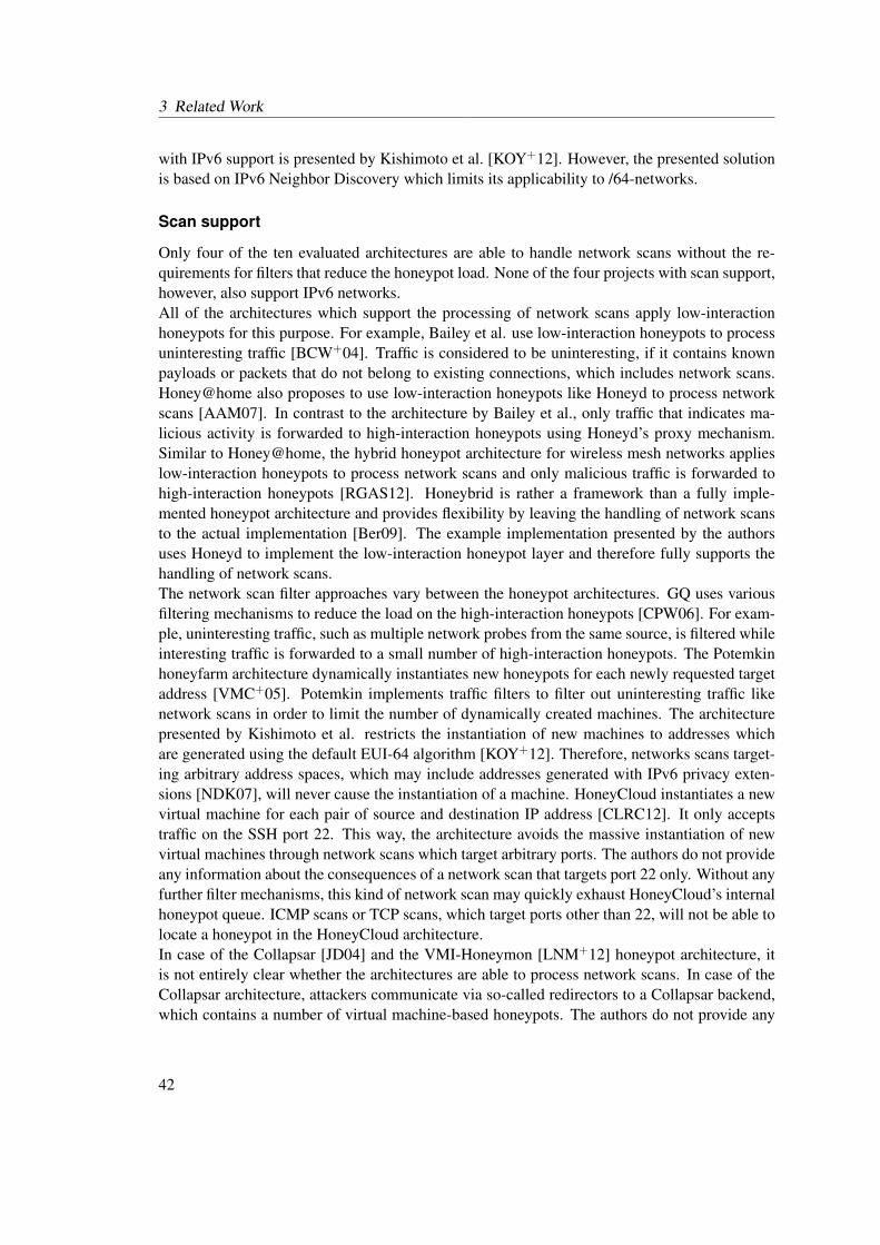
3 Related Work
with IPv6 support is presented by Kishimoto et al. [KOY+12]. However, the presented solutionis based on IPv6 Neighbor Discovery which limits its applicability to /64-networks.
Scan support
Only four of the ten evaluated architectures are able to handle network scans without the re-quirements for filters that reduce the honeypot load. None of the four projects with scan support,however, also support IPv6 networks.All of the architectures which support the processing of network scans apply low-interactionhoneypots for this purpose. For example, Bailey et al. use low-interaction honeypots to processuninteresting traffic [BCW+04]. Traffic is considered to be uninteresting, if it contains knownpayloads or packets that do not belong to existing connections, which includes network scans.Honey@home also proposes to use low-interaction honeypots like Honeyd to process networkscans [AAM07]. In contrast to the architecture by Bailey et al., only traffic that indicates ma-licious activity is forwarded to high-interaction honeypots using Honeyd’s proxy mechanism.Similar to Honey@home, the hybrid honeypot architecture for wireless mesh networks applieslow-interaction honeypots to process network scans and only malicious traffic is forwarded tohigh-interaction honeypots [RGAS12]. Honeybrid is rather a framework than a fully imple-mented honeypot architecture and provides flexibility by leaving the handling of network scansto the actual implementation [Ber09]. The example implementation presented by the authorsuses Honeyd to implement the low-interaction honeypot layer and therefore fully supports thehandling of network scans.The network scan filter approaches vary between the honeypot architectures. GQ uses variousfiltering mechanisms to reduce the load on the high-interaction honeypots [CPW06]. For exam-ple, uninteresting traffic, such as multiple network probes from the same source, is filtered whileinteresting traffic is forwarded to a small number of high-interaction honeypots. The Potemkinhoneyfarm architecture dynamically instantiates new honeypots for each newly requested targetaddress [VMC+05]. Potemkin implements traffic filters to filter out uninteresting traffic likenetwork scans in order to limit the number of dynamically created machines. The architecturepresented by Kishimoto et al. restricts the instantiation of new machines to addresses whichare generated using the default EUI-64 algorithm [KOY+12]. Therefore, networks scans target-ing arbitrary address spaces, which may include addresses generated with IPv6 privacy exten-sions [NDK07], will never cause the instantiation of a machine. HoneyCloud instantiates a newvirtual machine for each pair of source and destination IP address [CLRC12]. It only acceptstraffic on the SSH port 22. This way, the architecture avoids the massive instantiation of newvirtual machines through network scans which target arbitrary ports. The authors do not provideany information about the consequences of a network scan that targets port 22 only. Without anyfurther filter mechanisms, this kind of network scan may quickly exhaust HoneyCloud’s internalhoneypot queue. ICMP scans or TCP scans, which target ports other than 22, will not be able tolocate a honeypot in the HoneyCloud architecture.In case of the Collapsar [JD04] and the VMI-Honeymon [LNM+12] honeypot architecture, itis not entirely clear whether the architectures are able to process network scans. In case of theCollapsar architecture, attackers communicate via so-called redirectors to a Collapsar backend,which contains a number of virtual machine-based honeypots. The authors do not provide any
42

3.6 Survey of Hybrid Honeypots and Large-scale Honeyfarms
information about the handling of probe packets by redirectors. VMI-Honeymon builds uponHoneybrid and could theoretically be able to efficiently process network scans. However, thesample implementation of VMI-Honeymon differs from the proposed Honeybrid implementa-tion and it is not clear whether the authors added mechanisms to filter network scans.
IP Alignment
Two of the ten evaluated architectures make sure that the IP address of a high-interaction hon-eypot equals the address which was originally requested by an attacker. Six of the evaluatedarchitectures use proxy techniques, such as NAT, which result in different IP addresses on thehigh-interaction honeypots than originally requested. In two cases, the IP configuration was notfurther specified.The Potemkin honeyfarm architecture [VMC+05] and the adaptive honeypot system to captureIPv6 address scans, presented by Kishimoto et al. [KOY+12], dynamically instantiate new ma-chines on-demand. Both architectures deploy high-interaction honeypots based on incomingrequests without the utilization of low-interaction honeypots. Kishimoto et al. remotely config-ure the IPv6 address of a machine via SSH before forwarding an attacker to the machine. Thisapproach, however, requires an SSH daemon running on the high-interaction honeypots whichmay reveal honeypot systems where an installed SSH daemon is unusual. It is also not clearwhether Kishimoto et al. hide all traces of the IP address reconfiguration, for example, by delet-ing the corresponding shell history entries. Potemkin uses a different approach to reconfigureIP addresses. The Potemkin architecture includes a clone manager which creates new honey-pot instances by cloning an already running Xen base machine image. As soon as the cloningprocess is finished, the clone manager sends an unspecified configuration packet to the newlyinstantiated machine. This configuration packet contains the desired IP address and triggers theaddress reconfiguration.In six of the ten evaluated projects, the addresses of the high-interaction honeypots differ fromthe originally requested addresses. Bailey et al. apply a proxy component, which forwardsnew and unknown connection flows from low-interaction to a rigid number of high-interactionhoneypots [BCW+04] . The IP addresses on these honeypots stay unaltered and the proxy im-plementation is required to tunnel connections to the high-interaction honeypots. GQ employsNAT to translate the public IP addresses to the actual honeypot addresses [CPW06]. Honey-brid’s prototype implementation works with a fixed number of high-interaction honeypots andimplements a Redirection Engine which proxies connections from low- to the high-interactionhoneypots [Ber09]. The process does not include an address reconfiguration. The same appliesto the VMI-Honeymon architecture which is built upon Honeybrid [LNM+12]. Collapsar is an-other architecture, which applies a fixed number of high-interaction honeypots in its backend.Network packets are directly injected into the virtualized NICs of the virtual machine-basedhigh-interaction honeypots in order to avoid an IP address reconfiguration.In case of the HoneyCloud [CLRC12] architecture and the hybrid system for wireless meshnetworks [RGAS12], it is not clear whether an IP reconfiguration is applied. In case of theHoneyCloud architecture, the system description indicates that the public IP addresses are onlyconfigured on the HoneyCloud gateway, which is located between attackers and high-interactionhoneypots.
43
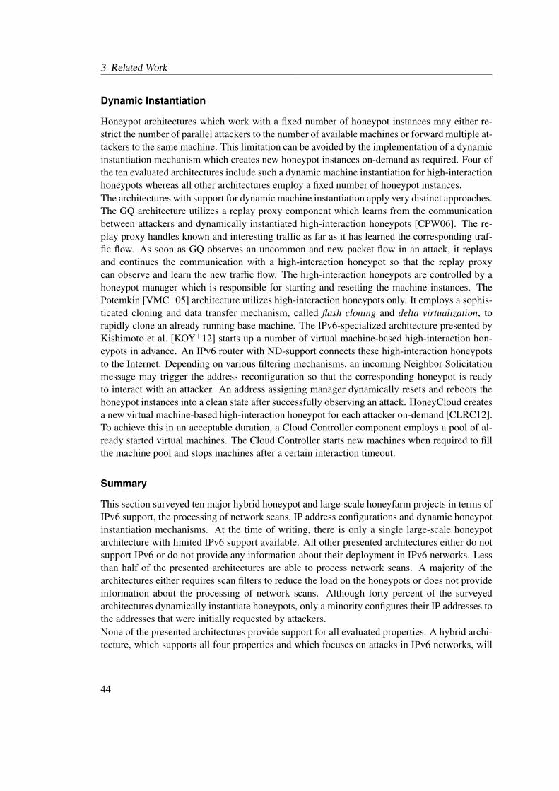
3 Related Work
Dynamic Instantiation
Honeypot architectures which work with a fixed number of honeypot instances may either re-strict the number of parallel attackers to the number of available machines or forward multiple at-tackers to the same machine. This limitation can be avoided by the implementation of a dynamicinstantiation mechanism which creates new honeypot instances on-demand as required. Four ofthe ten evaluated architectures include such a dynamic machine instantiation for high-interactionhoneypots whereas all other architectures employ a fixed number of honeypot instances.The architectures with support for dynamic machine instantiation apply very distinct approaches.The GQ architecture utilizes a replay proxy component which learns from the communicationbetween attackers and dynamically instantiated high-interaction honeypots [CPW06]. The re-play proxy handles known and interesting traffic as far as it has learned the corresponding traf-fic flow. As soon as GQ observes an uncommon and new packet flow in an attack, it replaysand continues the communication with a high-interaction honeypot so that the replay proxycan observe and learn the new traffic flow. The high-interaction honeypots are controlled by ahoneypot manager which is responsible for starting and resetting the machine instances. ThePotemkin [VMC+05] architecture utilizes high-interaction honeypots only. It employs a sophis-ticated cloning and data transfer mechanism, called flash cloning and delta virtualization, torapidly clone an already running base machine. The IPv6-specialized architecture presented byKishimoto et al. [KOY+12] starts up a number of virtual machine-based high-interaction hon-eypots in advance. An IPv6 router with ND-support connects these high-interaction honeypotsto the Internet. Depending on various filtering mechanisms, an incoming Neighbor Solicitationmessage may trigger the address reconfiguration so that the corresponding honeypot is readyto interact with an attacker. An address assigning manager dynamically resets and reboots thehoneypot instances into a clean state after successfully observing an attack. HoneyCloud createsa new virtual machine-based high-interaction honeypot for each attacker on-demand [CLRC12].To achieve this in an acceptable duration, a Cloud Controller component employs a pool of al-ready started virtual machines. The Cloud Controller starts new machines when required to fillthe machine pool and stops machines after a certain interaction timeout.
Summary
This section surveyed ten major hybrid honeypot and large-scale honeyfarm projects in terms ofIPv6 support, the processing of network scans, IP address configurations and dynamic honeypotinstantiation mechanisms. At the time of writing, there is only a single large-scale honeypotarchitecture with limited IPv6 support available. All other presented architectures either do notsupport IPv6 or do not provide any information about their deployment in IPv6 networks. Lessthan half of the presented architectures are able to process network scans. A majority of thearchitectures either requires scan filters to reduce the load on the honeypots or does not provideinformation about the processing of network scans. Although forty percent of the surveyedarchitectures dynamically instantiate honeypots, only a minority configures their IP addresses tothe addresses that were initially requested by attackers.None of the presented architectures provide support for all evaluated properties. A hybrid archi-tecture, which supports all four properties and which focuses on attacks in IPv6 networks, will
44

3.6 Survey of Hybrid Honeypots and Large-scale Honeyfarms
be presented later in this thesis. One main requirement for this architecture is an IPv6 compati-ble low-interaction honeypot solution which is able to simulate a large number of machines. Thedevelopment of this low-interaction honeypot solution is presented in the subsequent chapter.
45

3 Related Work
46
4 IPv6 Network Attack Monitoring withHoneydv6
Section 3.6 surveyed major hybrid honeypot and large-scale honeyfarm architectures and cameto the conclusion that the number of available IPv6 compatible solutions is very limited.A main contribution of this thesis is a hybrid honeypot architecture which is especially designedfor the attack monitoring in IPv6 networks. An essential requirement for this architecture isan IPv6 compatible multipurpose low-interaction honeypot layer which is able to efficientlysimulate a large number of machines. At the time of writing, there is no such honeypot solutionavailable. This section presents a newly developed low-interaction IPv6 honeypot that is basedon the well-known honeypot Honeyd [Pro04] and which aims at filling the gap of low-interactionhoneypots for IPv6 networks.Honeyd was chosen to provide the base layer for the new IPv6 honeypot architecture becauseof its ability to simulate entire IPv4 networks on a single host. An extension of Honeyd’s cus-tomized network stack allows the deployment of large IPv6 honeynets with millions of IPv6addresses on a single machine.Honeyd has already been proven to efficiently trap attackers in IPv4 networks. This was con-firmed by researchers of the Edith Cowan University in Perth, who conducted a study to findout whether Honeyd’s emulation capabilities are sufficient to deceive a human attacker [Gup03].Based on a questionnaire, the research team selected six university students to attack a newlyspawned Honeyd-based honeynet. In order to retrieve realistic attack results, the actual intentionof the experiment was left concealed and the candidates were left in the misguided believe thattheir hacking skills were tested on a real network. After a number of test iterations they came tothe conclusion that Honeyd could successfully deceive the attackers and that it is able to provideuseful log information about the conducted attacks.Even though Honeyd’s customized network stack provides great flexibility when it comes tohandling of thousands of IP addresses, it impedes an extension for IPv6 networks. The exist-ing IPv6 functionality of the underlying host operating system cannot be reused and must bereimplemented. The customized packet processing has to be modified and essential parts ofentirely new protocols such as ICMPv6 or the Neighbor Discovery (ND) protocol have to beimplemented.The following sections present and explain all major IPv6-specific features and modificationsto Honeyd. This is followed by performance measurements which show, that the newly imple-mented IPv6 version of Honeyd, called Honeydv6, does not perform significantly worse thanits IPv4 counterpart. Some implementations require a deeper understanding of Honeyd’s inter-nal architecture. This insight into the technical background is provided in the correspondingsections when required.
47
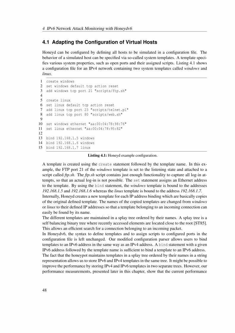
4 IPv6 Network Attack Monitoring with Honeydv6
4.1 Adapting the Configuration of Virtual Hosts
Honeyd can be configured by defining all hosts to be simulated in a configuration file. Thebehavior of a simulated host can be specified via so-called system templates. A template speci-fies various system properties, such as open ports and their assigned scripts. Listing 4.1 showsa configuration file for an IPv4 network containing two system templates called windows andlinux.
1 create windows2 set windows default tcp action reset3 add windows tcp port 21 "scripts/ftp.sh"45 create linux6 set linux default tcp action reset7 add linux tcp port 23 "scripts/telnet.pl"8 add linux tcp port 80 "scripts/web.sh"9
10 set windows ethernet "aa:00:04:78:98:76"11 set linux ethernet "aa:00:04:78:95:82"1213 bind 192.168.1.5 windows14 bind 192.168.1.6 windows15 bind 192.168.1.7 linux
Listing 4.1: Honeyd example configuration.
A template is created using the create statement followed by the template name. In this ex-ample, the FTP port 21 of the windows template is set to the listening state and attached to ascript called ftp.sh. The ftp.sh script contains just enough functionality to capture all log-in at-tempts, so that an actual log-in is not possible. The set statement assigns an Ethernet addressto the template. By using the bind statement, the windows template is bound to the addresses192.168.1.5 and 192.168.1.6 whereas the linux template is bound to the address 192.168.1.7.Internally, Honeyd creates a new template for each IP address binding which are basically copiesof the original defined template. The names of the copied templates are changed from windowsor linux to their defined IP addresses so that a template belonging to an incoming connection caneasily be found by its name.The different templates are maintained in a splay tree ordered by their names. A splay tree is aself balancing binary tree where recently accessed elements are located close to the root [ST85].This allows an efficient search for a connection belonging to an incoming packet.In Honeydv6, the syntax to define templates and to assign scripts to configured ports in theconfiguration file is left unchanged. Our modified configuration parser allows users to bindtemplates to an IPv6 address in the same way as an IPv4 address. A bind statement with a givenIPv6 address followed by the template name is sufficient to bind a template to an IPv6 address.The fact that the honeypot maintains templates in a splay tree ordered by their names in a stringrepresentation allows us to store IPv6 and IPv4 templates in the same tree. It might be possible toimprove the performance by storing IPv4 and IPv6 templates in two separate trees. However, ourperformance measurements, presented later in this chapter, show that the current performance
48
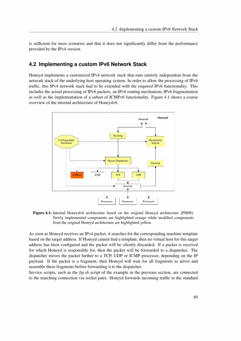
4.2 Implementing a custom IPv6 Network Stack
is sufficient for most scenarios and that it does not significantly differ from the performanceprovided by the IPv4 version.
4.2 Implementing a custom IPv6 Network Stack
Honeyd implements a customized IPv4 network stack that runs entirely independent from thenetwork stack of the underlying host operating system. In order to allow the processing of IPv6traffic, this IPv4 network stack had to be extended with the required IPv6 functionality. Thisincludes the actual processing of IPv6 packets, an IPv6 routing mechanism, IPv6 fragmentationas well as the implementation of a subset of ICMPv6 functionality. Figure 4.1 shows a coarseoverview of the internal architecture of Honeydv6.
Figure 4.1: Internal Honeydv6 architecture based on the original Honeyd architecture [PH08].Newly implemented components are highlighted orange while modified componentsfrom the original Honeyd architecture are highlighted yellow.
As soon as Honeyd receives an IPv4 packet, it searches for the corresponding machine templatebased on the target address. If Honeyd cannot find a template, then no virtual host for this targetaddress has been configured and the packet will be silently discarded. If a packet is receivedfor which Honeyd is responsible for, then the packet will be forwarded to a dispatcher. Thedispatcher moves the packet further to a TCP, UDP or ICMP processor, depending on the IPpayload. If the packet is a fragment, then Honeyd will wait for all fragments to arrive andassemble these fragments before forwarding it to the dispatcher.Service scripts, such as the ftp.sh script of the example in the previous section, are connectedto the matching connection via socket pairs. Honeyd forwards incoming traffic to the standard
49
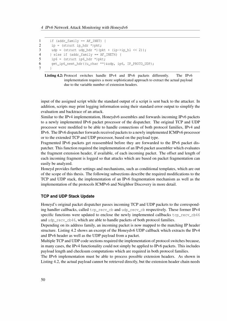
4 IPv6 Network Attack Monitoring with Honeydv6
1 if (addr_family == AF_INET) {2 ip = (struct ip_hdr *)pkt;3 udp = (struct udp_hdr *)(pkt + (ip->ip_hl << 2));4 } else if (addr_family == AF_INET6) {5 ip6 = (struct ip6_hdr *)pkt;6 get_ip6_next_hdr((u_char **)&udp, ip6, IP_PROTO_UDP);7 }
Listing 4.2: Protocol switches handle IPv4 and IPv6 packets differently. The IPv6implementation requires a more sophisticated approach to extract the actual payloaddue to the variable number of extension headers.
input of the assigned script while the standard output of a script is sent back to the attacker. Inaddition, scripts may print logging information using their standard error output to simplify theevaluation and backtrace of an attack.Similar to the IPv4 implementation, Honeydv6 assembles and forwards incoming IPv6 packetsto a newly implemented IPv6 packet processor of the dispatcher. The original TCP and UDPprocessor were modified to be able to handle connections of both protocol families, IPv4 andIPv6. The IPv6 dispatcher forwards received packets to a newly implemented ICMPv6 processoror to the extended TCP and UDP processor, based on the payload type.Fragmented IPv6 packets get reassembled before they are forwarded to the IPv6 packet dis-patcher. This function required the implementation of an IPv6 packet assembler which evaluatesthe fragment extension header, if available, of each incoming packet. The offset and length ofeach incoming fragment is logged so that attacks which are based on packet fragmentation caneasily be analyzed.Honeyd provides further settings and mechanisms, such as conditional templates, which are outof the scope of this thesis. The following subsections describe the required modifications to theTCP and UDP stack, the implementation of an IPv6 fragmentation mechanism as well as theimplementation of the protocols ICMPv6 and Neighbor Discovery in more detail.
TCP and UDP Stack Update
Honeyd’s original packet dispatcher passes incoming TCP and UDP packets to the correspond-ing handler callbacks, called tcp_recv_cb and udp_recv_cb respectively. These former IPv4specific functions were updated to enclose the newly implemented callbacks tcp_recv_cb46and udp_recv_cb46, which are able to handle packets of both protocol families.Depending on its address family, an incoming packet is now mapped to the matching IP headerstructure. Listing 4.2 shows an excerpt of the Honeydv6 UDP callback which extracts the IPv4and IPv6 header as well as the UDP payload from a packet.Multiple TCP and UDP code sections required the implementation of protocol switches because,in many cases, the IPv4 functionality could not simply be applied to IPv6 packets. This includespayload length and checksum computations which are required in both protocol families.The IPv6 implementation must be able to process possible extension headers. As shown inListing 4.2, the actual payload cannot be retrieved directly, but the extension header chain needs
50

4.2 Implementing a custom IPv6 Network Stack
1 struct tuple {2 ...3 //currently used to store the ipv4 addresses4 ip_addr_t ip_src;5 ip_addr_t ip_dst;6 //currently used to store the ipv6 addresses7 struct addr src_addr;8 struct addr dst_addr;9 uint16_t sport;
10 uint16_t dport;11 ...12 };
Listing 4.3: Excerpt of the modified tuple structure which maintains common attributes of aconnection.
to be traversed first. A newly implemented function, called get_ip6_next_hdr, implementsthe header chain evaluation and provides a pointer to the requested extension header or to theactual payload.Honeyd maintains UDP and TCP connections in special structures called udp_con and tcp_conrespectively. As shown in Listing 4.3, these connection structures include a pointer to a tuplestructure which holds common connection details, such as address and port pairs of a connection.Honeyd originally used the variables ip_src and ip_dst of type ip_addr_t to store IPv4addresses of a connection. Due to its smaller size, the ip_addr_t is not eligible to store IPv6addresses, so that the fields src_addr and dst_addr had to be added to the tuple structure inorder to store IPv6 addresses. All functions in Honeydv6, which require access to the addressof a connection, process either of the two address entries, depending of the connection’s addressfamily.
Fragmentation
IPv6 fragmentation handling differs from IPv4 insofar as only source nodes may fragment pack-ets. The newly implemented function ip6_send_fragments handles the fragmentation of out-going IPv6 packets that are larger than the Maximum Transmission Unit (MTU). The reassem-bling of incoming fragmented packets is done by another newly implemented function calledip6_fragment. All fragments are maintained in a splay tree using the fragment6 structureshown in Listing 4.4.Besides source and destination addresses, fragment length and a fragment identification value,the structure contains a queue which stores received fragments belonging to a packet. Whena packet arrives, the function ip6_fragment_find is used to search for already received frag-ments in the splay tree. If the received packet is the first received fragment, then the functionip6_fragment_new is used to insert a new entry into the splay tree. If other fragments havealready been received, then ip6_insert_fragment is used to add the packet to the fragmentqueue.
51
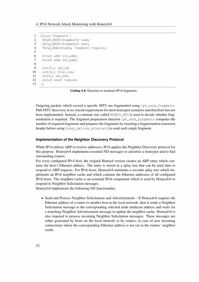
4 IPv6 Network Attack Monitoring with Honeydv6
1 struct fragment6 {2 SPLAY_ENTRY(fragment6) node;3 TAILQ_ENTRY(fragment6) next;4 TAILQ_HEAD(frag6q, frag6ent) fraglist;56 struct addr src_addr;7 struct addr dst_addr;89 uint32_t ip6_id;
10 uint32_t total_len;11 uint8_t nxt_hdr;12 struct event timeout;13 };
Listing 4.4: Structure to maintain IPv6 fragments.
Outgoing packets which exceed a specific MTU are fragmented using ip6_send_fragments.Path MTU discovery in no crucial requirement for most honeypot scenarios and therefore has notbeen implemented. Instead, a constant size called HONEYD_MTU is used to decide whether frag-mentation is required. The fragment preparation function ip6_send_fragments computes thenumber of required fragments and prepares the fragments by inserting a fragmentation extensionheader before using honey_deliver_ethernet6 to send each single fragment.
Implementation of the Neighbor Discovery Protocol
While IPv4 utilizes ARP to resolve addresses, IPv6 applies the Neighbor Discovery protocol forthis purpose. Honeydv6 implements essential ND messages to advertise a honeypot and to findsurrounding routers.For every configured IPv4 host, the original Honeyd version creates an ARP entry which con-tains the host’s Ethernet address. The entry is stored in a splay tree that can be used later torespond to ARP requests. For IPv6 hosts, Honeydv6 maintains a seconds splay tree which im-plements an IPv6 neighbor cache and which contains the Ethernet addresses of all configuredIPv6 hosts. The neighbor cache is an essential IPv6 component which is used by Honeydv6 torespond to Neighbor Solicitation messages.Honeydv6 implements the following ND functionality:
• Send and Process Neighbor Solicitations and Advertisements - If Honeydv6 requires theEthernet address of a router or another host in the local network, then it sends a NeighborSolicitation message to the corresponding solicited node multicast address and waits fora matching Neighbor Advertisement message to update the neighbor cache. Honeydv6 isalso required to process incoming Neighbor Solicitation messages. These messages areeither generated by hosts on the local network or by routers, in case of new incomingconnections where the corresponding Ethernet address is not yet in the routers’ neighborcache.
52
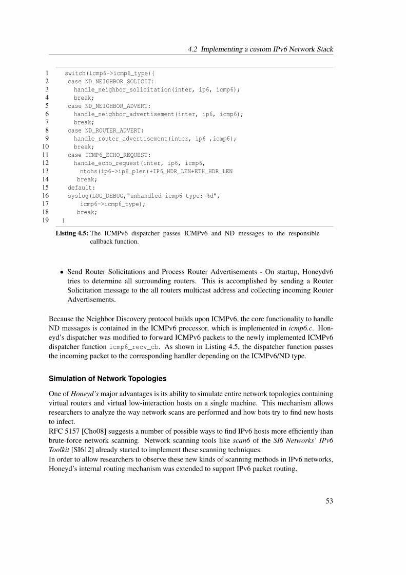
4.2 Implementing a custom IPv6 Network Stack
1 switch(icmp6->icmp6_type){2 case ND_NEIGHBOR_SOLICIT:3 handle_neighbor_solicitation(inter, ip6, icmp6);4 break;5 case ND_NEIGHBOR_ADVERT:6 handle_neighbor_advertisement(inter, ip6, icmp6);7 break;8 case ND_ROUTER_ADVERT:9 handle_router_advertisement(inter, ip6 ,icmp6);
10 break;11 case ICMP6_ECHO_REQUEST:12 handle_echo_request(inter, ip6, icmp6,13 ntohs(ip6->ip6_plen)+IP6_HDR_LEN+ETH_HDR_LEN14 break;15 default:16 syslog(LOG_DEBUG,"unhandled icmp6 type: %d",17 icmp6->icmp6_type);18 break;19 }
Listing 4.5: The ICMPv6 dispatcher passes ICMPv6 and ND messages to the responsiblecallback function.
• Send Router Solicitations and Process Router Advertisements - On startup, Honeydv6tries to determine all surrounding routers. This is accomplished by sending a RouterSolicitation message to the all routers multicast address and collecting incoming RouterAdvertisements.
Because the Neighbor Discovery protocol builds upon ICMPv6, the core functionality to handleND messages is contained in the ICMPv6 processor, which is implemented in icmp6.c. Hon-eyd’s dispatcher was modified to forward ICMPv6 packets to the newly implemented ICMPv6dispatcher function icmp6_recv_cb. As shown in Listing 4.5, the dispatcher function passesthe incoming packet to the corresponding handler depending on the ICMPv6/ND type.
Simulation of Network Topologies
One of Honeyd’s major advantages is its ability to simulate entire network topologies containingvirtual routers and virtual low-interaction hosts on a single machine. This mechanism allowsresearchers to analyze the way network scans are performed and how bots try to find new hoststo infect.RFC 5157 [Cho08] suggests a number of possible ways to find IPv6 hosts more efficiently thanbrute-force network scanning. Network scanning tools like scan6 of the SI6 Networks’ IPv6Toolkit [SI612] already started to implement these scanning techniques.In order to allow researchers to observe these new kinds of scanning methods in IPv6 networks,Honeyd’s internal routing mechanism was extended to support IPv6 packet routing.
53
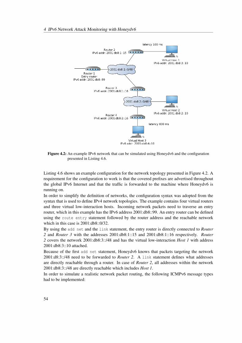
4 IPv6 Network Attack Monitoring with Honeydv6
Figure 4.2: An example IPv6 network that can be simulated using Honeydv6 and the configurationpresented in Listing 4.6.
Listing 4.6 shows an example configuration for the network topology presented in Figure 4.2. Arequirement for the configuration to work is that the covered prefixes are advertised throughoutthe global IPv6 Internet and that the traffic is forwarded to the machine where Honeydv6 isrunning on.In order to simplify the definition of networks, the configuration syntax was adopted from thesyntax that is used to define IPv4 network topologies. The example contains four virtual routersand three virtual low-interaction hosts. Incoming network packets need to traverse an entryrouter, which in this example has the IPv6 address 2001:db8::99. An entry router can be definedusing the route entry statement followed by the router address and the reachable networkwhich in this case is 2001:db8::0/32.By using the add net and the link statement, the entry router is directly connected to Router2 and Router 3 with the addresses 2001:db8:1::15 and 2001:db8:1::16 respectively. Router2 covers the network 2001:db8:3::/48 and has the virtual low-interaction Host 1 with address2001:db8:3::10 attached.Because of the first add net statement, Honeydv6 knows that packets targeting the network2001:d8:3::/48 need to be forwarded to Router 2. A link statement defines what addressesare directly reachable through a router. In case of Router 2, all addresses within the network2001:db8:3::/48 are directly reachable which includes Host 1.In order to simulate a realistic network packet routing, the following ICMPv6 message typeshad to be implemented:
54
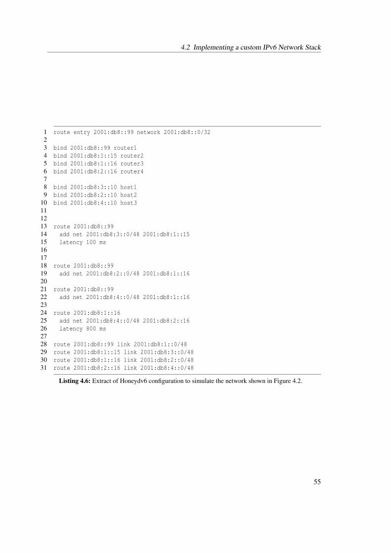
4.2 Implementing a custom IPv6 Network Stack
1 route entry 2001:db8::99 network 2001:db8::0/3223 bind 2001:db8::99 router14 bind 2001:db8:1::15 router25 bind 2001:db8:1::16 router36 bind 2001:db8:2::16 router478 bind 2001:db8:3::10 host19 bind 2001:db8:2::10 host2
10 bind 2001:db8:4::10 host3111213 route 2001:db8::9914 add net 2001:db8:3::0/48 2001:db8:1::1515 latency 100 ms161718 route 2001:db8::9919 add net 2001:db8:2::0/48 2001:db8:1::162021 route 2001:db8::9922 add net 2001:db8:4::0/48 2001:db8:1::162324 route 2001:db8:1::1625 add net 2001:db8:4::0/48 2001:db8:2::1626 latency 800 ms2728 route 2001:db8::99 link 2001:db8:1::0/4829 route 2001:db8:1::15 link 2001:db8:3::0/4830 route 2001:db8:1::16 link 2001:db8:2::0/4831 route 2001:db8:2::16 link 2001:db8:4::0/48
Listing 4.6: Extract of Honeydv6 configuration to simulate the network shown in Figure 4.2.
55
4 IPv6 Network Attack Monitoring with Honeydv6
• Time Exceeded - Each time an IPv6 packet traverses a router, its hop limit gets decreased.As soon as the hop limit reaches zero, Honeydv6 sends an ICMPv6 Time Exceeded mes-sage back to the source.
• Destination Unreachable - If a packet is sent to an undefined address within Honeydv6’saddress space or to a closed UDP port then the honeypot replies with an ICMPv6 Desti-nation Unreachable message.
Both packet types are essential in order to make network scanning tools like traceroute6 workand to allow attackers exploring the virtual network.Honeyd’s internal routing functionality required various extensions to handle IPv6 traffic. Thisincludes the computation of the hop limit values and functions to find and compare IPv6 net-works. Details about the routing implementation can be found in the published sources of Hon-eydv61 and are left out of this thesis for conciseness reasons.The simulation of physical network properties, as provided by the IPv4 Honeyd version, was alsoadapted to support IPv6 traffic. It is possible to define factors, such as packet loss or networklatency, as shown in Listing 4.6. In this example, a packet transfer from Router 1 to Virtual Host1 takes about 100 milliseconds while a packet from Router 3 to Virtual Host 3 needs about 800milliseconds. If no latency is set, then a packet is passed to the next hop without any extra delayexcept the time needed for computation.
4.3 Pitfalls
The development of Honeydv6 revealed two major pitfalls which, if disregarded, may cause anunexpected and hardly debuggable system behavior: embedded scope indices, which compli-cated address comparisons needed to route packets, and hidden dynamic arrays, which causedmemory access violations. The following two subsections explain both issues in more detail.
Embedded Scope Indices
Honeydv6 uses the function intf_get of the network library libdnet [Dug15] to retrieve all localinterfaces. On some operating systems, however, the retrieved link-local interface addressescontained scope indices which were directly embedded in the address.Scope indices are required by an operating system to determine the interface that should beused when sending a packet to a local destination in cases where multiple local interfaces areavailable. Some operating systems rely on the fact that the 54 bits which follow a local net-work prefix must be set to zero [HD06] and use these spare bits to embed a scope index. Anexample for such an operating system is OpenBSD2, which integrated the IPv6 implementationof the KAME project [LJS10, Had02]. In order to convert these addresses into valid link-localaddresses, the scope indices must be removed. A new function called addr_remove_scope_idwas implemented to remove potential embedded scope indices from link-local addresses.
1https://redmine.cs.uni-potsdam.de/projects/honeydv62http://www.openbsd.org
56
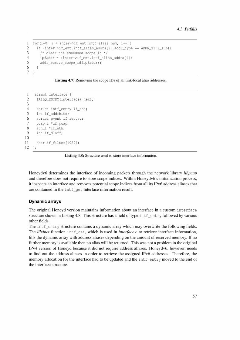
4.3 Pitfalls
1 for(i=0; i < inter->if_ent.intf_alias_num; i++){2 if (inter->if_ent.intf_alias_addrs[i].addr_type == ADDR_TYPE_IP6){3 /* clear the embedded scope id */4 ip6addr = &inter->if_ent.intf_alias_addrs[i];5 addr_remove_scope_id(ip6addr);6 }7 }
Listing 4.7: Removing the scope IDs of all link-local alias addresses.
1 struct interface {2 TAILQ_ENTRY(interface) next;34 struct intf_entry if_ent;5 int if_addrbits;6 struct event if_recvev;7 pcap_t *if_pcap;8 eth_t *if_eth;9 int if_dloff;
1011 char if_filter[1024];12 };
Listing 4.8: Structure used to store interface information.
Honeydv6 determines the interface of incoming packets through the network library libpcapand therefore does not require to store scope indices. Within Honeydv6’s initialization process,it inspects an interface and removes potential scope indices from all its IPv6 address aliases thatare contained in the intf_get interface information result.
Dynamic arrays
The original Honeyd version maintains information about an interface in a custom interfacestructure shown in Listing 4.8. This structure has a field of type intf_entry followed by variousother fields.The intf_entry structure contains a dynamic array which may overwrite the following fields.The libdnet function intf_get, which is used in interface.c to retrieve interface information,fills the dynamic array with address aliases depending on the amount of reserved memory. If nofurther memory is available then no alias will be returned. This was not a problem in the originalIPv4 version of Honeyd because it did not require address aliases. Honeydv6, however, needsto find out the address aliases in order to retrieve the assigned IPv6 addresses. Therefore, thememory allocation for the interface had to be updated and the intf_entry moved to the end ofthe interface structure.
57
4 IPv6 Network Attack Monitoring with Honeydv6
4.4 Covering huge Address Spaces using Random IPv6 RequestProcessing
The huge IPv6 address space makes it hard, if not impossible, for an attacker to find a single hoston the network by pure chance. While this fact is very welcome in common networks, it impedesthe behavioral analysis of actual attackers who may or may not be able to find a machine. Newapproaches are required to observe IPv6 network scan techniques and analyze attackers actionswhen they actually find a running host.Honeydv6 implements a new mechanism which dynamically creates simulated hosts on-demandand randomly accepts IPv6 connections. This approach makes sure that, after a certain numberof connection attempts, an attacker will definitely find a machine to exploit. Honeydv6 logs allconnection attempts, even to IPv6 addresses that are not explicitly defined in the configurationfile. This enables researchers to analyze IPv6 network scans and to observe new and unknownscan patterns.The dynamic host creation works as follows: when a packet arrives, Honeydv6 tries to find aconfigured virtual low-interaction host which matches the packet’s destination. If no host can befound, then a new template will dynamically be created with a specified acceptance probability.A user can enable the so-called IPv6 random mode by adding the randomipv6 statement fol-lowed by the acceptance probability to the Honeydv6 configuration file. In order to define thetemplate that should be used for dynamically created machines, a name of a default template hasto be specified right after the acceptance probability.An example configuration is provided in Listing 4.9. The configuration defines the templaterandomdefault to be the default template. The default template has HTTP port 80 and FTPport 21 opened and assigned to the corresponding scripts. Besides the configured open portsand the matching script assignments, the template has a defined Ethernet address. Honeydv6replaces the last three bytes of this Ethernet address with randomly generated bytes for eachnewly created template, which corresponds to Honeyd’s default behavior. Currently, only onedefault template is supported.If Honeydv6 rejects a request and skips the machine creation, then the target address will beblacklisted. Future requests to a blacklisted address will always be ignored to keep the systemstate consistent and to avoid revealing the honeypot. Depending on the given probability value,the list of blacklisted machines may become much larger than the list of instantiated machines.Eventually, a simple list structure that stores all blacklisted machines would quickly exhaustthe memory of a Honeydv6 host. Therefore, Honeydv6 implements a Bloom filter to storeblacklisted machines. A Bloom filter is a probabilistic data structure, maintaining a large bitmask of a fixed size [BM03]. When adding an element to a Bloom filter, its hash is mappedto the bit mask. The bit mask can be used later to test whether an entry has been added to thefilter structure. Honeydv6 uses the filter to mark each blocked address. A special characteristicof a Bloom filter is that the test for added entries is probabilistic and does not always returnthe correct answer. The filter is able to test whether an entry has not been added to it with aprobability of 100 percent. However, due to its limited size, it is possible that multiple entriesmap to the same bits in the mask so that the filter is not able to certainly determine whether anentry has already been added to it. Hence, a destination address which is detected as blocked by
58

4.5 Tricking Nmap’s IPv6 Operating System Fingerprinting
1 create randomdefault2 set randomdefault default tcp action reset3 add randomdefault tcp port 21 "scripts/ftp.sh"4 add randomdefault tcp port 80 "scripts/web.sh"5 set randomdefault ethernet "aa:00:04:78:98:78"67 randomipv6 0.5 randomdefault 25689 randomexclude 2001:db8::1
10 randomexclude 2001:db8::211 randomexclude 2001:db8::3
Listing 4.9: Honeyd configuration to randomly accept IPv6 connections.
Honeydv6 may have actually never been observed in the network before. However, if the Bloomfilter returns that an address has not been blocked then Honeydv6 can continue the dynamictemplate creation. This behavior is accepted in favor of the low amount of memory that isconsumed by the filter structure.In some cases it may be useful to exclude certain addresses from the automatic template creation,e.g. if production nodes are located in the same network as Honeydv6. This can be done by usingthe randomexclude statement. An excluded address is automatically blacklisted and Honeydv6will ignore all requests to this address.It is possible to define an upper bound for the number of dynamically created templates by thehoneypot. This number can be defined in the Honeydv6 configuration file next to the defaulttemplate name. In the example above, the maximum number of allowed templates is 256. It isimportant to restrict the number of dynamically created virtual low-interaction hosts in order toavoid memory-exhaustion attacks. Each created machine and each blacklisted address causesmemory consumption until the maximum number of allowed machines is reached.It is recommended to restrict the number of dynamically created machines as well as the accep-tance probability to an appropriate low value, depending on the use case. A large number ofuniformly distributed host may easily reveal the honeypot and should therefore be avoided.
4.5 Tricking Nmap’s IPv6 Operating System Fingerprinting
A commonly used software to perform network reconnaissance is the Nmap Security Scan-ner [Lyo11]. Besides various port scanning techniques, Nmap implements a mechanism to al-low the remote classification of operating systems. This is accomplished by sending varioustest packets to a desired destination and matching the responses against a local fingerprintingdatabase. This section presents how Honeydv6 leverages Nmap’s fingerprinting database todeceive the security scanner by imitating various operating systems.Internally, Nmap applies different approaches to determine an operating system, depending onwhether the target is an IPv4 or an IPv6 host. Even though this section focuses on the operatingsystem classification in IPv6 networks, it is beneficial to consider the structure of an IPv4 fin-
59
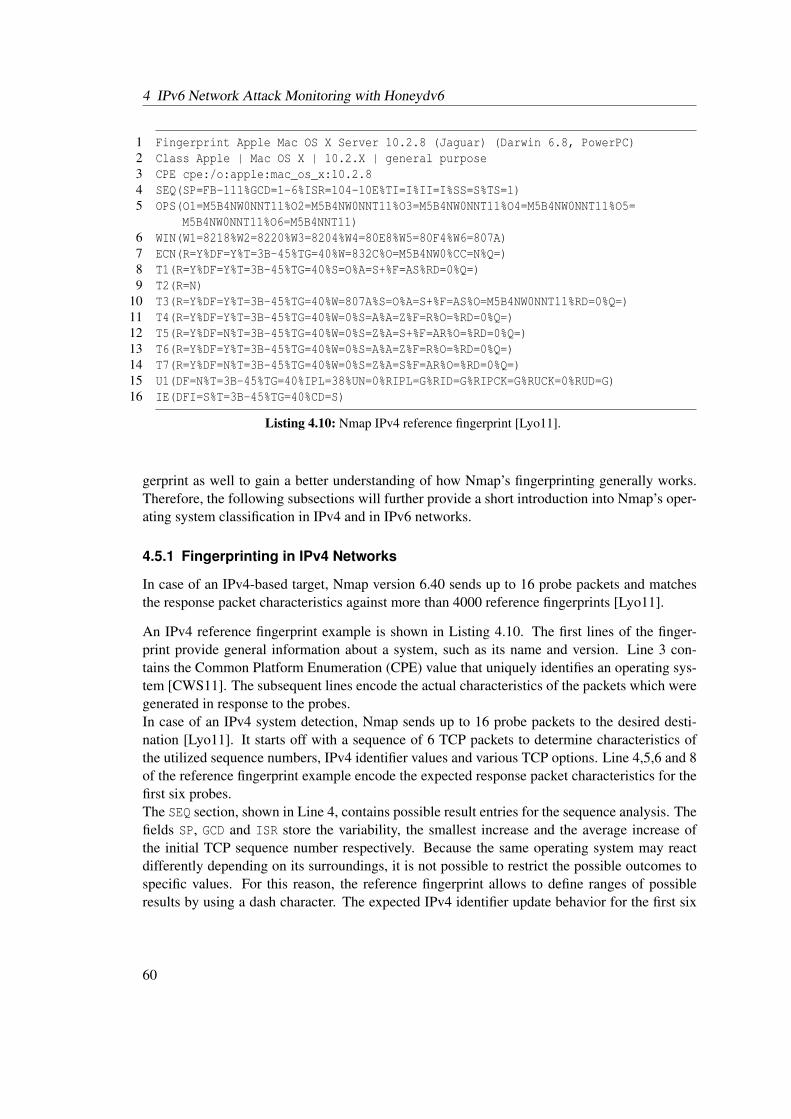
4 IPv6 Network Attack Monitoring with Honeydv6
1 Fingerprint Apple Mac OS X Server 10.2.8 (Jaguar) (Darwin 6.8, PowerPC)2 Class Apple | Mac OS X | 10.2.X | general purpose3 CPE cpe:/o:apple:mac_os_x:10.2.84 SEQ(SP=FB-111%GCD=1-6%ISR=104-10E%TI=I%II=I%SS=S%TS=1)5 OPS(O1=M5B4NW0NNT11%O2=M5B4NW0NNT11%O3=M5B4NW0NNT11%O4=M5B4NW0NNT11%O5=
M5B4NW0NNT11%O6=M5B4NNT11)6 WIN(W1=8218%W2=8220%W3=8204%W4=80E8%W5=80F4%W6=807A)7 ECN(R=Y%DF=Y%T=3B-45%TG=40%W=832C%O=M5B4NW0%CC=N%Q=)8 T1(R=Y%DF=Y%T=3B-45%TG=40%S=O%A=S+%F=AS%RD=0%Q=)9 T2(R=N)
10 T3(R=Y%DF=Y%T=3B-45%TG=40%W=807A%S=O%A=S+%F=AS%O=M5B4NW0NNT11%RD=0%Q=)11 T4(R=Y%DF=Y%T=3B-45%TG=40%W=0%S=A%A=Z%F=R%O=%RD=0%Q=)12 T5(R=Y%DF=N%T=3B-45%TG=40%W=0%S=Z%A=S+%F=AR%O=%RD=0%Q=)13 T6(R=Y%DF=Y%T=3B-45%TG=40%W=0%S=A%A=Z%F=R%O=%RD=0%Q=)14 T7(R=Y%DF=N%T=3B-45%TG=40%W=0%S=Z%A=S%F=AR%O=%RD=0%Q=)15 U1(DF=N%T=3B-45%TG=40%IPL=38%UN=0%RIPL=G%RID=G%RIPCK=G%RUCK=0%RUD=G)16 IE(DFI=S%T=3B-45%TG=40%CD=S)
Listing 4.10: Nmap IPv4 reference fingerprint [Lyo11].
gerprint as well to gain a better understanding of how Nmap’s fingerprinting generally works.Therefore, the following subsections will further provide a short introduction into Nmap’s oper-ating system classification in IPv4 and in IPv6 networks.
4.5.1 Fingerprinting in IPv4 Networks
In case of an IPv4-based target, Nmap version 6.40 sends up to 16 probe packets and matchesthe response packet characteristics against more than 4000 reference fingerprints [Lyo11].
An IPv4 reference fingerprint example is shown in Listing 4.10. The first lines of the finger-print provide general information about a system, such as its name and version. Line 3 con-tains the Common Platform Enumeration (CPE) value that uniquely identifies an operating sys-tem [CWS11]. The subsequent lines encode the actual characteristics of the packets which weregenerated in response to the probes.In case of an IPv4 system detection, Nmap sends up to 16 probe packets to the desired desti-nation [Lyo11]. It starts off with a sequence of 6 TCP packets to determine characteristics ofthe utilized sequence numbers, IPv4 identifier values and various TCP options. Line 4,5,6 and 8of the reference fingerprint example encode the expected response packet characteristics for thefirst six probes.The SEQ section, shown in Line 4, contains possible result entries for the sequence analysis. Thefields SP, GCD and ISR store the variability, the smallest increase and the average increase ofthe initial TCP sequence number respectively. Because the same operating system may reactdifferently depending on its surroundings, it is not possible to restrict the possible outcomes tospecific values. For this reason, the reference fingerprint allows to define ranges of possibleresults by using a dash character. The expected IPv4 identifier update behavior for the first six
60
4.5 Tricking Nmap’s IPv6 Operating System Fingerprinting
probes is stored in the TI field. In case of the reference fingerprint, this value is set to I toindicate that the identifier is increasing with each probe. Nmap furthermore evaluates responsesto packets containing a TCP timestamp option [JBB92]. The result of this evaluation is stored inthe TS field of the fingerprint. In case of the reference fingerprint example, this value is set to 1to indicate a 2 Hz timestamp generation frequency. The SEQ section of the reference fingerprintcontains two more fields called II and SS. These fields contain IPv4 identifier characteristics thatare derived from subsequent test results. The SS field encodes whether the TCP and successiveICMP sequences share the same IPv4 identifier values. The II field is the ICMP counterpart tothe TI field and encodes the increase of IPv4 identification values for ICMP probes.For the first six probe packets, a selection of TCP options and their order in the responses isstored in the O1 to O6 fields of OPS section in line 5. An option is encoded into a single characterand, depending on the option type, concatenated to its value. For example, the reference finger-print contains a Maximum Segment Size option with a value of 5B4 [Pos81c]. Similar to the OPSsection, the WIN section in line 6 contains the possible TCP windows sizes for each response ofthe six initial probe packets.Section T1 describes multiple expected IP and TCP header values and options in response tothe first of the six TCP requests. For example, the R field encodes whether there is an expectedresponse. In case of the example fingerprint reference, this values is set to yes (Y). Similarly,the DF fields indicates whether the Don’t Fragment bit is set in the IPv4 header [Pos81b]. TheT1 section further encodes expected TTL values, windows sizes, sequence and acknowledgmentnumbers as well as TCP flags and options. These fields are described in detail in [Lyo11]and are out of scope of this document. Nmap generates six further TCP probes with differentconfigurations. Similar to T1, their expected response properties are encoded in the same way insection T2 to T7.The ECN section, shown in line 7 of the reference fingerprint example, provides informationabout the expected response to a single probe that evaluates the Explicit Congestion Notification(ECN) support of the target system. ECN is normally used to prevent packet drops in overloadednetworks utilizing different IP and TCP header flags [RFB01]. The format of the ECN sectioncorresponds to the format of the T sections. However, it includes an additional field called CC todescribe whether the target supports ECN.A reference fingerprint also includes characteristics for packets that are sent in response to UDPand ICMP probes. Nmap sends a single UDP packet with a specific payload to a closed port andtwo further ICMP echo requests. The expected results for these tests are mainly stored in the U1and IE section respectively, shown in Line 15 and 16 in Listing 4.10. Both sections contain someof the fields that are known from the T sections. In addition, the U1 section encodes informationabout the IP length (IPL, RIPL), IPv4 ID and checksum(RID, RIPCK), faulty use of unused headersections (UN) and the completeness of the UDP payload in the error response (RUD).The anticipated properties of the responses to the two ICMP echo request messages are stored inthe IE section. Similar to the DF field of the T sections, the DFI field in the IE section describesif an enabled Don’t Fragment bit can be expected in the IPv4 header. The CD field describes thesystems behavior regarding ICMP code modifications. Although a code value of zero is expectedin case of an echo reply message, the example system shown in Listing 4.10 only mirrors codevalues from the corresponding echo requests, which is indicated by a value of S [Pos81a, Lyo11].
61
4 IPv6 Network Attack Monitoring with Honeydv6
More details about Nmap’s IPv4 fingerprinting mechanism, the individual properties and theirencoding are presented in "The Official Nmap Project Guide to Network Discovery and SecurityScanning" and left out of this thesis for conciseness reasons [Lyo11].Honeyd 1.5c allows a virtual IPv4 host to mimic the behavior of a specific operating system sothat an Nmap scan retrieves a desired response. The honeypot detects Nmap probe packets andevaluates the Nmap IPv4 reference fingerprint database in order to generate appropriate replies3.The subsequent subsections introduce Nmap’s method for IPv6 fingerprinting and present Hon-eydv6’s approach to imitate various operating systems in IPv6 networks.
4.5.2 Fingerprinting in IPv6 Networks
Similar to the fingerprinting mechanism implemented in the IPv4 version of Honeyd, Honeydv6supports the imitation of operating systems for Nmap scanners in IPv6 networks. Even thoughmost of the generated probe packets are very similar to the IPv4 probes, Nmap utilizes a com-pletely different approach when evaluating the responses. Nmap’s IPv4 fingerprinting mecha-nism matches responses against thousands of existing reference fingerprints located in a localdatabase. As shown in the previous subsection, the database format is rather simple. Differ-ent system configurations and intermediate network devices may alter an operating system’sfingerprint [FGM+15]. Therefore, a single operating system may require multiple reference fin-gerprints which leads to an unnecessary large number of database entries which are difficult tomaintain. In order to mitigate this problem, Nmap’s IPv6 fingerprinting engine is based on adifferent approach. It utilizes a machine learning method called logistic regression to classify anoperating system. Fifield et al. present this fingerprinting concept in detail in their publication"Remote Operating System Classification over IPv6" [FGM+15]. This section introduces thebasic idea of logistic regression in simplified terms and presents how Honeydv6 leverages thisconcept to trick Nmap scanners in IPv6 networks.
Logistic Regression for Operating Systems Classifications
Regression analysis is a statistical method to compute the relationship between dependent andpredictor variables [CH13]. Predictor variables can be considered as an input set which leadsto a certain response, also called a dependent variable. In order to understand Nmap’s finger-printing approach, it is sufficient to consider the characteristics of probe response packets to bepredictor variables. For example, a possible predictor variable may be the initial sequence num-ber of a TCP header. Nmap refers to predictor variables as features, which is a common termin the scope of machine learning [Lyo11]. In the best case, a set of operating system character-istics refers to a specific operating system. In Nmap’s use case, the response, and therefore thedependent variable, is binary: a set of characteristics either forms a specific operating system orit does not. By utilizing a statistical method, called logistic regression, Nmap is able to computethe probability that a set of observed network packet properties belongs to a specific operatingsystem. A fundamental operation of this approach is the so-called logistic regression function,which computes a probability π from set of predictor variables x1 to xp [CH13]:
3Details about the Honeyd IPv4 operating system fingerprinting are presented by Valli and Warren in "Honeyd -A OS Fingerprinting Artifice." [Val03].
62
4.5 Tricking Nmap’s IPv6 Operating System Fingerprinting
π = Pr(Y = 1|X1 = x1, ...,Xp = xp) =eβ0+β1x1+β2x2+...+βpxp
1+ eβ0+β1x1+β2x2+...+βpxp
The coefficients β0 to βp must be computed from a set of existing training data with the supportof particular optimization functions. Details about these underlying methods are not required tounderstand how Honeydv6 deceives Nmap’s IPv6 fingerprinting mechanism and are out of scopeof this document. Chatterjee and Hadi provide more details on this topic and the correspondingcomputation models in "Regression Analysis by Example" [CH13].In order to compute the probability π that a number of packet characteristics x1 to xp representa specific operating system, Nmap computes the output of the logistic regression function foreach known operating system. In order to obtain the β-values for the logistic regression function,Nmap uses a set of existing IPv6 fingerprint samples to train its regression model. Nmap usesLIBLINEAR4 to perform a so-called one-vs-rest multiclass classification for all possible op-erating systems [FGM+15]. The LIBLINEAR one-vs-rest classification, also called one-vs-allclassification, computes the β-values for each operating system by splitting the training data intotwo different sets: a set containing the reference values of the selected operating system and asecond set containing the reference values of all other operating systems [RK04]. Furthermore,LIBLINEAR is configured to apply a machine learning mechanism called L2-regularization.This method scales the coefficients to avoid the problem of overfitting, which in simple termsmeans that the computed logistic regression function is too training data specific and ineligibleto compute the probability for new inputs [McC15]. Nmap’s computed model, including thescales and mean values for each operating system class, is stored and distributed within its of-ficial source code in a file called FPModel.cc. The evaluation of this model file is essential forHoneydv6 to be able to respond to a remote Nmap operating system classification.
IPv6 Fingerprinting Probes
Fifield et al. proposed and implemented 18 qualified probe packets into Nmap’s IPv6 finger-printing engine [FGM+15]. This subsection provides a general overview of the utilized IPv6probes based on their publication. A majority of the packets aim to collect the same informationas an IPv4 fingerprinting process and therefore have a similar packet structure.
S1 to S6: As in the case of an IPv4 system classification, an IPv6 probing begins with a trans-mission of a series of six TCP packets, named S1 to S6, with specific configurations in an 100milliseconds interval to an open port. All packets contain different TCP options in order to forcethe target system to use a different negotiation for new connections. The responses to theseprobes mainly help to determine the behavior of a system’s sequence and identification numbergenerator, similar to the information gathered for the SEQ section in Listing 4.10.
TECN, T2 to T7: Following the sequence probes S1 to S6, Nmap sends seven further TCP pack-ets to the desired destination. These packets evaluate a system’s response behavior to differentflag combinations and are referred to as TECN and T2 to T7. TECN is the IPv6 counterpart to
4http://www.csie.ntu.edu.tw/~cjlin/liblinear/
63
4 IPv6 Network Attack Monitoring with Honeydv6
the ECN probe of an IPv4 operating system classification and evaluates the support of conges-tion control [RFB01]. The packets T2 to T7 mostly differ in their flag and port configurations.The first half of the packets is sent to an open port whereas the second half is sent to a closedport. Aim of these probes is the evaluation of a system’s response behavior when handling un-common TCP flag combinations.
U1: Nmap sends a single UDP packet to a closed port and therefore tries to trigger an ICMPv6Destination Unreachable message. This is another test which is derived from Nmap’s IPv4 fin-gerprinting implementation, as shown in the reference fingerprint in Listing 4.10. According toFifield et al., this UDP probe has no provable value for the outcome of a fingerprinting and wasadded for historical reasons only [FGM+15].
IE1, IE2, NI: Nmap sends three different ICMPv6 packets to a target of an IPv6 fingerprinting.The first probe is an ICMPv6 echo request message that contains a code value unequal to zero.Similar to the IE probes of an IPv4 fingerprinting, this test verifies whether a target system mir-rors invalid ICMPv6 code values. The IE2 probe is an ICMPv6 echo request message whichcarries an invalid IPv6 header chain, containing the Hop-by-Hop header twice. According toFifield et al., most operating systems either drop this probe or respond with various ICMPv6error messages [FGM+15]. Another novel probe includes a Node Information Query, which isused in practice to gather information about a host’s name or addresses [CH06]. According toFifield et al. and the official Nmap documentation, Nmap sends a Node Information Query ask-ing for a list of the targets IPv4 addresses. Fifield et al. state that most tested operating systemsmisinterpret this message and respond with a hostname. It is important to note that in contrastto what the official Nmap documentation states, Nmap does not evaluate a Node InformationReply. Version 6.40 of Nmap obviously prepares a Node Information Query in its fingerprintingengine, however, it does not consider its result in the fingerprinting model. It is not clear whetherthe results gathered from a Node Information Reply are evaluated in future Nmap version.
NS: If an IPv6 fingerprinting targets a host in the local network, then Nmap sends a NeighborSolicitation message to the target and evaluates flags and options of the corresponding response.
Selected Logistic Regression Features
After sending the probe packets, Nmap converts selected response packet attributes into a fea-ture vector for the logistic regression function. In case of Nmap version 6.40, this feature vectorcontains 659 different features. The features are obtained from the following response packetproperties:
TCP_ISR: Similar to the ISR field in the SEQ section, shown in the reference fingerprint in List-ing 4.10, the TCP_ISR feature stores the average increase of the initial sequence number for theS1 to S6 probes.
PLEN: The PLEN feature is derived from the payload length that is defined in the IPv6 baseheader. In Nmap 6.40, it is one of two features that are generated from a field which cannot be
64
4.5 Tricking Nmap’s IPv6 Operating System Fingerprinting
found in the IPv4 header.
TC: This is the second feature that is derived from an IPv6 only field. As suggested by its name,it encodes the value of the utilized traffic class which is stored in the IPv6 base header.
TCP_WINDOW: For each TCP packet, the communicated Window Size value is encoded into afeature called TCP_WINDOW.
TCP_FLAG_*: Nmap uses 12 different features for each probe packet to evaluate encounteredTCP flags. This includes default flags, such as SYN and ACK, but also the values which are ob-served in the adjacent reserved section. Within the Nmap model source code, features containingvalid flags are referenced using their name’s first character attached to the prefix TCP_FLAG_.For example, the SYN flag is referred to as TCP_FLAG_S. The reserved fields are referred to asTCP_FLAG_RES8 to TCP_FLAG_RES11.
TCP_OPT_0-16 and TCP_OPTLEN_0-16: Nmap evaluates the first 16 encountered optioncodes and lengths of each TCP response packet. The corresponding results are stored in theTCP_OPT_0 to TCP_OPT_15 and TCP_OPTLEN_0 to TCP_OPTLEN_15 features respectively.
TCP_MSS: The TCP_MSS feature contains the evaluation of the maximum TCP segment size thatis provided in the probe responses.
TCP_SACKOK: An operating system may support selective acknowledgments, which allows aTCP connection to resend a selection of lost packets rather than an entire TCP window [MMFR96].The TCP_SACKOK feature encodes whether selective acknowledgments are permitted or not.
TCP_WSCALE: The 16-bit Window Size field of the TCP header may be insufficient to encodeappropriately large values required for fast TCP data transfers. The introduction of a TCP Win-dow Scale option helps to further increase the TCP Window Size by providing a shift value thatis applied to the Window Size [JBB92]. If a probed operating system makes use of the TCPWindow Scaling option then the shift value is stored in the TCP_WSCALE feature.
All features except for the TCP_ISR feature are derived from all possible probe response packetsand stored sequentially in the Nmap fingerprinting model. As shown in Listing 4.11, the Nmapfingerprinting model contains feature scaling values to normalize each packet attribute to havea value in the range [0,1]. Features that could not be derived from a probe response are set to avalue of -1 in the feature vector [FGM+15].
4.5.3 Implementation of an IPv6 Personality Engine for Honeydv6
Honeydv6 implements an IPv6 personality engine which allows the imitation of arbitrary op-erating systems contained in Nmap’s IPv6 fingerprinting model. The implementation leveragesthe fact that the Nmap source code includes, besides the scale factors and logistic regression
65

4 IPv6 Network Attack Monitoring with Honeydv6
1 double FPscale[][2] = {2 { -20, 0.0416667 }, /* S1.PLEN */3 { -0, 0.00520833 }, /* S1.TC */4 { -20, 0.0416667 }, /* S2.PLEN */5 { -0, 0.00520833 }, /* S2.TC */6 { -20, 0.05 }, /* S3.PLEN */7 ...8 };
Listing 4.11: Nmap scaling factors for IPv6 fingerprinting features.
1 double FPmean[][659] = {2 /* Linux 2.6.38 - 3.2 */3 { +0.83333333, +0.00000000, +0.83333333,...4 /* Linux 2.6.32 - 2.6.39 */5 { +0.83333333, +0.00000000, +0.83333333,6 /* HP ProCurve 2520G switch */7 { +1.00000000, +0.00000000, +1.00000000,8 ...
Listing 4.12: Excerpt of Nmap’s mean value array which contains mean values for each IPv6feature. It is located in the FPModel.cc source file of the official Nmap source code.
coefficients, mean values for each feature of every operating system. An excerpt of these meanvalues is shown in Listing 4.12. Actually, Nmap makes use of these mean values when comput-ing novelty values for the probed targets [FGM+15]. If the feature vector of a probed operatingsystem exceeds a certain novelty threshold then the user is shown a message stating that theoperating system classification did not yield definitive results. This mechanism prevents Nmapfrom determining obscure classification results. Honeydv6 evaluates the mean values to forgepackets that conform to a desired operating system in response to an Nmap fingerprinting.A Python converter script convert.py, which is part of the Honeydv6 source code, is able to au-tomatically generate a personality engine from an Nmap fingerprinting model. It requires thelocation of Nmap’s FPModel.cc source file as an input and generates the corresponding Hon-eydv6 source file personality6.c. The converter parses the afore mentioned FPScale and FPMeanvectors and generates a newly developed personality6 entry for each operating system. Dur-ing this process, each mean value of the FPMean vector is rescaled using the FPScale valuesto retrieve the original packet properties. The format of a personality6 structure is shown inListing 4.13. The personality structures are embedded into Honeydv6’s personality engine ini-tialization function personality6_init. The embedding process is achieved by using Pythonstring templates. A file called personality6.tmpl.c contains the scaffolding for the Honeydv6personality engine. The $personality6_config_new_calls placeholder within the templatefile is replaced with initialization calls for the computed personality6 entries during the con-version process.The IPv6 personality engine detects Nmap scan probes based on a selection of packet charac-
66
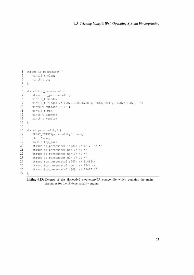
4.5 Tricking Nmap’s IPv6 Operating System Fingerprinting
1 struct ip_personate6 {2 uint16_t plen;3 uint8_t tc;4 };56 struct tcp_personate6 {7 struct ip_personate6 ip;8 uint16_t window;9 uint16_t flags; /* 0,0,0,0,RES8,RES9,RES10,RES11,C,E,U,A,P,R,S,F */
10 uint8_t options[16][2];11 uint16_t mss;12 uint8_t sackok;13 uint8_t wscale;14 };1516 struct personality6 {17 SPLAY_ENTRY(personality6) node;18 char *name;19 double tcp_isr;20 struct ip_personate6 ie[2]; /* IE1, IE2 */21 struct ip_personate6 ni; /* NI */22 struct ip_personate6 ns; /* NS */23 struct ip_personate6 u1; /* U1 */24 struct tcp_personate6 s[6]; /* S1-S6*/25 struct tcp_personate6 tecn; /* TECN */26 struct tcp_personate6 t[6]; /* T2-T7 */27 };
Listing 4.13: Excerpt of the Honeydv6 personality6.h source file which contains the mainstructures for the IPv6 personality engine.
67

4 IPv6 Network Attack Monitoring with Honeydv6
teristics. For example, the S5 probe can be identified by a maximum TCP segment size of 536bytes and a window scaling value of 10. Honeydv6’s personality engine matches incoming traf-fic against known Nmap probe characteristics and forges expected responses. Depending on theencountered probes and their protocol, Honeydv6 applies the following response packet trans-formations:
TCP - S1..S6, T2..T7, TECN: When sending responses to Nmap’s TCP probes, Honeydv6 derivesthe expected Window Size values, TCP flags and TCP options directly from the defined finger-print entry. The values are stored in the personality6 structure, as shown in Listing 4.13. For anumber of known TCP options, the personality engine uses the length values that are defined inthe corresponding standard. All other options and their length are extracted from the fingerprintentry. The Traffic Class field of the IPv6 base header is derived directly from the fingerprintentry for all TCP packets. It is not required to adapt the IPv6 Payload Length value because it isdeduced from the inserted TCP options. Similar to its IPv4 counterpart, the IPv6 personality en-gine provides two main functions called tcp_personality6 and tcp_personality6_optionsto implement the TCP packet forgery.
ICMPv6 - IE1, IE2: In case of the two ICMPv6 echo request message probes, Honeydv6 ex-tracts the expected Payload Length value from the fingerprint and mirrors the request data backto the client. If the expected length is longer than the received data, then Honeydv6 applies apayload padding. Similar to the TCP probes, the Traffic Class field in the IPv6 base header iscopied from corresponding fingerprint entry.
ICMPv6 - NI: Although Nmap does not yet evaluate the NI probe response, Honeydv6 wasextended to support the handling of Node Information Queries in order to provide better finger-printing results for future Nmap versions. If an operating system personality requires Honeydv6to send an answer to a Node Information Query, then it prepares the corresponding Node In-formation Reply with the Traffic Class and Payload Length that will later be derived from theNmap fingerprinting model. Honeydv6 currently mirrors the Qtype value from the request anduses a Code value of zero, which indicates a successful reply [CH06]. If a Node InformationQuery targets a virtual low-interaction host which has no personality defined then the responseCode of the Node Information Reply is set to 1 to indicate a refused answer.
UDP - U1: Nmap’s U1 probe connects to a closed UDP port and tries to trigger an ICMPv6Destination Unreachable message. The response generated by Honeydv6 includes the expectedpart of the invoking packet. The packet processing is equivalent to the processing of IE1 andIE2 probes.
NS: Similar to the processing of the TCP and ICMPv6 probes, the Traffic Class value for theNeighbor Solicitation probe is directly derived from the system’s fingerprint entry. Dependingon whether the expected Payload Length value exceeds a threshold of 28 bytes, Honeydv6 at-taches a Target link-layer address option to the Neighbor Advertisement in order to increase thepacket length [NNSS07].
68
4.6 Honeydv6 Performance Evaluation
If the Traffic Class or Payload Length has a value of -1 in the fingerprinting model for a specificprobe packet then the personality engine causes the discard of a response. The personalityengine provides a function called personality6_ip6_response to test whether Nmap expectsa response for an incoming probe.A user can enable the operating system imitation by using the personality6 statement in theHoneydv6 configuration file. For example, the configuration statement set OS personality6"Linux 2.6.38 - 3.2" causes Honeydv6 to mimic a Linux operating system for requests thattarget the virtual low-interaction host OS.Besides through various manual tests, the functioning of Honeydv6’s IPv6 fingerprinting imita-tion could successfully be verified with the help of a blind study. Within the scope of a bachelorthesis, a student was asked to remotely determine the operating systems of three different andallegedly real machines [Spl16]. Two of these servers were actually Honeydv6 machines whichsimulated a Linux 2.6.18 and a Windows Server 2012 R2. The student successfully determinedthe desired operating systems using Nmap version 7 without noticing that the machines wereactually honeypot instances.
4.6 Honeydv6 Performance Evaluation
Honeydv6 provides a superset of the original Honeyd 1.5c functionality. It is able to handleIPv6 traffic and still provides the established IPv4 capabilities. The implementation of the IPv6functionality keeps the number of modifications to the IPv4 source code as low as possible. Thisavoids new programming errors and negative impacts on the IPv4 stack performance. Never-theless, in some cases, minor modifications to the IPv4 work flow had to be done. This sectionpresents measurement results to quantify the performance of the modified IPv4 and the new IPv6implementation in Honeydv6.
4.6.1 IPv4 and IPv6 Throughput Comparison
In order to evaluate the performance impact of the IPv6 modifications, the average applicationlayer throughput of the original Honeyd 1.5c was compared with the throughput of Honeydv6.A newly developed Honeyd benchmark service script and a corresponding client allows to mea-sure the time needed to transfer large files over the network to the honeypot. Honeyd 1.5c andHoneydv6 were installed on a Fujitsu PRIMERGY TX200 S5 Server with an Intel Xeon pro-cessor 5500 series and 4096 MB of RAM running Ubuntu 12.04. The benchmark client wasinstalled on a Lenovo ThinkPad L520 with an Intel i5-2450M CPU and 4096 MB of RAM. Bothmachines were connected via a Brocade FWS648G FastIron switch using Gigabit Ethernet.Table 4.1 shows the results for transferring 50 MB and 100 MB traffic from the client via IPv4and IPv6 to the honeypot benchmark service.
69

4 IPv6 Network Attack Monitoring with Honeydv6
Filesize Honeyd 1.5c (IPv4) Honeydv6 (IPv4) Honeydv6 (IPv6)50 MB 15.98 s 16.19 s 16.33 s
100 MB 31.85 s 31.94 s 32.36 s
Table 4.1: Comparison of transmission time in seconds between the original Honeyd version 1.5cand Honeydv6.
For each experiment, Table 4.1 shows the median from 5 runs. It takes about 16 seconds totransfer 50 MB to the honeypots and about twice as much time to transfer 100 MB.In case of transferring 50 MB over IPv4, the original version of Honeyd is approximately 0.2seconds faster than Honeydv6. For sending 100 MB, the original version was about 0.09 secondsfaster than its IPv6 counterpart. This indicates that the overhead is in the magnitude of themeasurement error and negligible. The overhead is most probably caused by a number of newlyadded IPv4/IPv6 switches in the source code. Furthermore, the IPv6 transfer is insignificantlyslower than the IPv4 transfer of both versions. Honeydv6 needed approximately 0.35 secondslonger than the original 1.5c version to transfer 50 MB and about 0.51 seconds longer to transfer100 MB over an IPv6 network.
4.6.2 Scalability of Honeydv6
While throughput measurements can help to get an impression of the performance impact causedby the IPv6 modifications, throughput is not a very useful criteria to evaluate a honeypot for itssuitability in a network. A honeypot like Honeyd rather needs to be able to handle a large numberof connections than transferring huge files.Provos and Holz, for example, measured the number of TCP requests per second that Honeydis able to process [PH08]. In order to evaluate the performance impact on the application layer,the web server benchmark servload [ZHS12]5 was employed to measure the number of HTTPGET requests per second, that Honeyd 1.5c and Honeydv6 is able to process. Servload is able toreplay a previously captured HTTP access log file based on the request timestamps. A generatedlog file, containing 20,000 HTTP GET requests, was used to send up to 600 requests per secondfrom different source addresses to both honeypot versions.Honeydv6 was configured to simulate a single machine with a running web server. The machinetemplate was bound to an IPv4 and an IPv6 address and port 80 was configured to apply themock web server script web.sh that is included in the original Honeyd version. The web.sh scriptsimulates a Microsoft IIS 5.0 server and, depending on the incoming request, delivers either adirectory listing of the server or a 404 NOT FOUND page. The generated benchmark requestsdemanded a non-existing index.html page so that the web.sh script responses with an HTTP 404NOT FOUND error code and an error message.As with the throughput measurements, the test run was executed with Honeyd 1.5c and the IPv4and IPv6 stack of Honeydv6.
5Download available from http://www.salbnet.org/
70
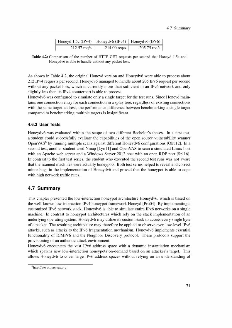
4.7 Summary
Honeyd 1.5c (IPv4) Honeydv6 (IPv4) Honeydv6 (IPv6)212.57 req/s 214.00 req/s 205.75 req/s
Table 4.2: Comparison of the number of HTTP GET requests per second that Honeyd 1.5c andHoneydv6 is able to handle without any packet loss.
As shown in Table 4.2, the original Honeyd version and Honeydv6 were able to process about212 IPv4 requests per second. Honeydv6 managed to handle about 205 IPv6 request per secondwithout any packet loss, which is currently more than sufficient in an IPv6 network and onlyslightly less than its IPv4 counterpart is able to process.Honeydv6 was configured to simulate only a single target for the test runs. Since Honeyd main-tains one connection entry for each connection in a splay tree, regardless of existing connectionswith the same target address, the performance difference between benchmarking a single targetcompared to benchmarking multiple targets is insignificant.
4.6.3 User Tests
Honeydv6 was evaluated within the scope of two different Bachelor’s theses. In a first test,a student could successfully evaluate the capabilities of the open source vulnerability scannerOpenVAS6 by running multiple scans against different Honeydv6 configurations [Oku12]. In asecond test, another student used Nmap [Lyo11] and OpenVAS to scan a simulated Linux hostwith an Apache web server and a Windows Server 2012 host with an open RDP port [Spl16].In contrast to the first test series, the student who executed the second test runs was not awarethat the scanned machines were actually honeypots. Both test series helped to reveal and correctminor bugs in the implementation of Honeydv6 and proved that the honeypot is able to copewith high network traffic rates.
4.7 Summary
This chapter presented the low-interaction honeypot architecture Honeydv6, which is based onthe well-known low-interaction IPv4 honeypot framework Honeyd [Pro04]. By implementing acustomized IPv6 network stack, Honeydv6 is able to simulate entire IPv6 networks on a singlemachine. In contrast to honeypot architectures which rely on the stack implementation of anunderlying operating system, Honeydv6 may utilize its custom stack to access every single byteof a packet. The resulting architecture may therefore be applied to observe even low-level IPv6attacks, such as attacks to the IPv6 fragmentation mechanism. Honeydv6 implements essentialfunctionality of ICMPv6 and the Neighbor Discovery protocol. These protocols support theprovisioning of an authentic attack environment.Honeydv6 encounters the vast IPv6 address space with a dynamic instantiation mechanismwhich spawns new low-interaction honeypots on-demand based on an attacker’s target. Thisallows Honeydv6 to cover large IPv6 address spaces without relying on an understanding of
6http://www.openvas.org
71

4 IPv6 Network Attack Monitoring with Honeydv6
existing IPv6 scan approaches. Final performance measurements show that Honeydv6 providesthe required performance to cover large IPv6 address spaces.
72
5 IPv6 Darknet Observations
The development of IPv6 honeypots requires an understanding of the threat level in IPv6 net-works. This chapter presents the results of two different darknet experiments, a 9-month ob-servation of a /48 darknet and a 17-months observation of a /34 darknet. The main objectivesof both experiments were the assessment of the threat level in IPv6 networks and an evaluationof the type of traffic that can be expected in IPv6 networks. A further intention was the ob-servation of IPv6 network scan approaches to confirm or disconfirm whether sophisticated scanapproaches, as presented in Section 2.3, do exist in the real world.
5.1 Nine Months of IPv6 Traffic Monitoring in a /48 darknet
A first darknet experiment was conducted in 2012. As part of the experiment, a new /48 IPv6darknet was installed and monitored for 9 months. The observation period included the timearound the World IPv6 Launch on the 6th of June, a day on which multiple large companiesenabled IPv6 access for their customers [Int15d]. The following subsections describe the instal-lation of the darknet, tools that were used to simplify the evaluation of darknet traffic and theactual results of the experiment.
5.1.1 Darknet Setup
The address space for the darknet experiment was provided by the tunnel broker HurricaneElectric1 and the incoming traffic was tunneled to a darknet monitor using a Simple InternetTransition (SIT) tunnel. A tcpdump-based monitoring script, shown in Appendix C, was used tocapture all incoming packets on the darknet monitor.
5.1.2 Automatic Traffic Analysis
Although the traffic rate in IPv6 darknets is still low compared to the amount of traffic that canbe observed in IPv4 darknets, it is not feasible to analyze all received packets manually andindividually. The traffic capture and analyzer tool tshark, which is part of the Wireshark distri-bution [The15b], was used as a basis for the development of a new darknet traffic analyzer script.The analyzer script computes and prints various packet statistics, such as the protocol distribu-tion, observed sources and destinations and most requested TCP and UDP ports. An excerpt ofthe script is shown in Appendix D. Some individual packets with special characteristics, such asuncommon TCP flag combinations, were analyzed separately after running the automatic trafficanalyzes.
1http://he.net
73
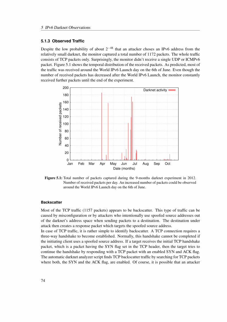
5 IPv6 Darknet Observations
5.1.3 Observed Traffic
Despite the low probability of about 2−48 that an attacker choses an IPv6 address from therelatively small darknet, the monitor captured a total number of 1172 packets. The whole trafficconsists of TCP packets only. Surprisingly, the monitor didn’t receive a single UDP or ICMPv6packet. Figure 5.1 shows the temporal distribution of the received packets. As predicted, most ofthe traffic was received around the World IPv6 Launch day on the 6th of June. Even though thenumber of received packets has decreased after the World IPv6 Launch, the monitor constantlyreceived further packets until the end of the experiment.
0
20
40
60
80
100
120
140
160
180
200
Jan Feb Mar Apr May Jun Jul Aug Sep Oct
Num
ber
of re
ceiv
ed p
ack
ets
Date (months)
Darknet activity
Figure 5.1: Total number of packets captured during the 9-months darknet experiment in 2012.Number of received packets per day. An increased number of packets could be observedaround the World IPv6 Launch day on the 6th of June.
Backscatter
Most of the TCP traffic (1157 packets) appears to be backscatter. This type of traffic can becaused by misconfiguration or by attackers who intentionally use spoofed source addresses outof the darknet’s address space when sending packets to a destination. The destination underattack then creates a response packet which targets the spoofed source address.In case of TCP traffic, it is rather simple to identify backscatter. A TCP connection requires athree-way handshake to become established. Normally, this handshake cannot be completed ifthe initiating client uses a spoofed source address. If a target receives the initial TCP handshakepacket, which is a packet having the SYN flag set in the TCP header, then the target tries tocontinue the handshake by responding with a TCP packet with an enabled SYN and ACK flag.The automatic darknet analyzer script finds TCP backscatter traffic by searching for TCP packetswhere both, the SYN and the ACK flag, are enabled. Of course, it is possible that an attacker
74
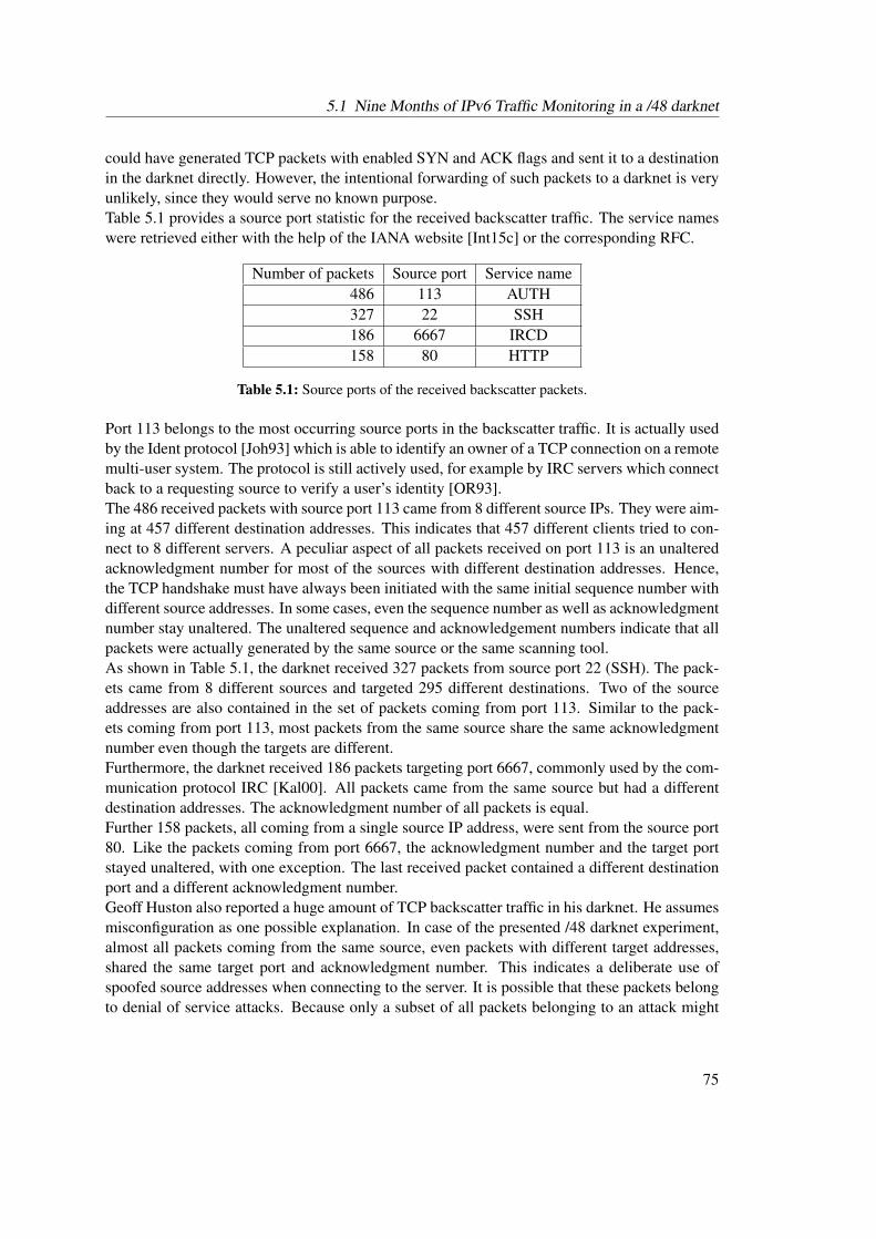
5.1 Nine Months of IPv6 Traffic Monitoring in a /48 darknet
could have generated TCP packets with enabled SYN and ACK flags and sent it to a destinationin the darknet directly. However, the intentional forwarding of such packets to a darknet is veryunlikely, since they would serve no known purpose.Table 5.1 provides a source port statistic for the received backscatter traffic. The service nameswere retrieved either with the help of the IANA website [Int15c] or the corresponding RFC.
Number of packets Source port Service name486 113 AUTH327 22 SSH186 6667 IRCD158 80 HTTP
Table 5.1: Source ports of the received backscatter packets.
Port 113 belongs to the most occurring source ports in the backscatter traffic. It is actually usedby the Ident protocol [Joh93] which is able to identify an owner of a TCP connection on a remotemulti-user system. The protocol is still actively used, for example by IRC servers which connectback to a requesting source to verify a user’s identity [OR93].The 486 received packets with source port 113 came from 8 different source IPs. They were aim-ing at 457 different destination addresses. This indicates that 457 different clients tried to con-nect to 8 different servers. A peculiar aspect of all packets received on port 113 is an unalteredacknowledgment number for most of the sources with different destination addresses. Hence,the TCP handshake must have always been initiated with the same initial sequence number withdifferent source addresses. In some cases, even the sequence number as well as acknowledgmentnumber stay unaltered. The unaltered sequence and acknowledgement numbers indicate that allpackets were actually generated by the same source or the same scanning tool.As shown in Table 5.1, the darknet received 327 packets from source port 22 (SSH). The pack-ets came from 8 different sources and targeted 295 different destinations. Two of the sourceaddresses are also contained in the set of packets coming from port 113. Similar to the pack-ets coming from port 113, most packets from the same source share the same acknowledgmentnumber even though the targets are different.Furthermore, the darknet received 186 packets targeting port 6667, commonly used by the com-munication protocol IRC [Kal00]. All packets came from the same source but had a differentdestination addresses. The acknowledgment number of all packets is equal.Further 158 packets, all coming from a single source IP address, were sent from the source port80. Like the packets coming from port 6667, the acknowledgment number and the target portstayed unaltered, with one exception. The last received packet contained a different destinationport and a different acknowledgment number.Geoff Huston also reported a huge amount of TCP backscatter traffic in his darknet. He assumesmisconfiguration as one possible explanation. In case of the presented /48 darknet experiment,almost all packets coming from the same source, even packets with different target addresses,shared the same target port and acknowledgment number. This indicates a deliberate use ofspoofed source addresses when connecting to the server. It is possible that these packets belongto denial of service attacks. Because only a subset of all packets belonging to an attack might
75
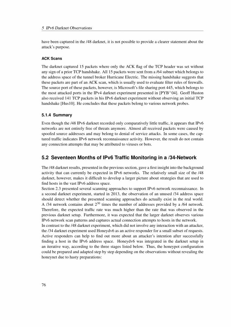
5 IPv6 Darknet Observations
have been captured in the /48 darknet, it is not possible to provide a clearer statement about theattack’s purpose.
ACK Scans
The darknet captured 15 packets where only the ACK flag of the TCP header was set withoutany sign of a prior TCP handshake. All 15 packets were sent from a /64 subnet which belongs tothe address space of the tunnel broker Hurricane Electric. The missing handshake suggests thatthese packets are part of an ACK scan, which is usually used to evaluate filter rules of firewalls.The source port of these packets, however, is Microsoft’s file sharing port 445, which belongs tothe most attacked ports in the IPv4 darknet experiment presented in [PYB+04]. Geoff Hustonalso received 141 TCP packets in his IPv6 darknet experiment without observing an initial TCPhandshake [Hus10]. He concludes that these packets belong to various network probes.
5.1.4 Summary
Even though the /48 IPv6 darknet recorded only comparatively little traffic, it appears that IPv6networks are not entirely free of threats anymore. Almost all received packets were caused byspoofed source addresses and may belong to denial of service attacks. In some cases, the cap-tured traffic indicates IPv6 network reconnaissance activity. However, the result do not containany connection attempts that may be attributed to viruses or bots.
5.2 Seventeen Months of IPv6 Traffic Monitoring in a /34-Network
The /48 darknet results, presented in the previous section, gave a first insight into the backgroundactivity that can currently be expected in IPv6 networks. The relatively small size of the /48darknet, however, makes it difficult to develop a larger picture about strategies that are used tofind hosts in the vast IPv6 address space.Section 2.3 presented several scanning approaches to support IPv6 network reconnaissance. Ina second darknet experiment, started in 2013, the observation of an unused /34 address spaceshould detect whether the presented scanning approaches do actually exist in the real world.A /34 network contains about 230 times the number of addresses provided by a /64 network.Therefore, the expected traffic rate was much higher than the rate that was observed in theprevious darknet setup. Furthermore, it was expected that the larger darknet observes variousIPv6 network scan patterns and captures actual connection attempts to hosts in the network.In contrast to the /48 darknet experiment, which did not involve any interaction with an attacker,the /34 darknet experiment used Honeydv6 as an active responder for a small subset of requests.Active responders can help to find out more about an attacker’s intention after successfullyfinding a host in the IPv6 address space. Honeydv6 was integrated in the darknet setup inan iterative way, according to the three stages listed below. Thus, the honeypot configurationcould be prepared and adapted step by step depending on the observations without revealing thehoneynet due to hasty preparations:
76
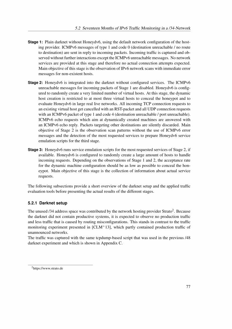
5.2 Seventeen Months of IPv6 Traffic Monitoring in a /34-Network
Stage 1: Plain darknet without Honeydv6, using the default network configuration of the host-ing provider. ICMPv6 messages of type 1 and code 0 (destination unreachable / no routeto destination) are sent in reply to incoming packets. Incoming traffic is captured and ob-served without further interactions except the ICMPv6 unreachable messages. No networkservices are provided at this stage and therefore no actual connection attempts expected.Main objective of this stage is the observation of IPv6 network scans with immediate errormessages for non-existent hosts.
Stage 2: Honeydv6 is integrated into the darknet without configured services. The ICMPv6unreachable messages for incoming packets of Stage 1 are disabled. Honeydv6 is config-ured to randomly create a very limited number of virtual hosts. At this stage, the dynamichost creation is restricted to at most three virtual hosts to conceal the honeypot and toevaluate Honeydv6 in large real live networks. All incoming TCP connection requests toan existing virtual host get cancelled with an RST-packet and all UDP connection requestswith an ICMPv6 packet of type 1 and code 4 (destination unreachable / port unreachable).ICMPv6 echo requests which aim at dynamically created machines are answered withan ICMPv6 echo reply. Packets targeting other destinations are silently discarded. Mainobjective of Stage 2 is the observation scan patterns without the use of ICMPv6 errormessages and the detection of the most requested services to prepare Honeydv6 serviceemulation scripts for the third stage.
Stage 3: Honeydv6 runs service emulation scripts for the most requested services of Stage 2, ifavailable. Honeydv6 is configured to randomly create a large amount of hosts to handleincoming requests. Depending on the observations of Stage 1 and 2, the acceptance ratefor the dynamic machine configuration should be as low as possible to conceal the hon-eypot. Main objective of this stage is the collection of information about actual servicerequests.
The following subsections provide a short overview of the darknet setup and the applied trafficevaluation tools before presenting the actual results of the different stages.
5.2.1 Darknet setup
The unused /34 address space was contributed by the network hosting provider Strato2. Becausethe darknet did not contain productive systems, it is expected to observe no production trafficand less traffic that is caused by routing misconfigurations. This stands in contrast to the trafficmonitoring experiment presented in [CLM+13], which partly contained production traffic ofunannounced networks.The traffic was captured with the same tcpdump-based script that was used in the previous /48darknet experiment and which is shown in Appendix C.
2https://www.strato.de
77
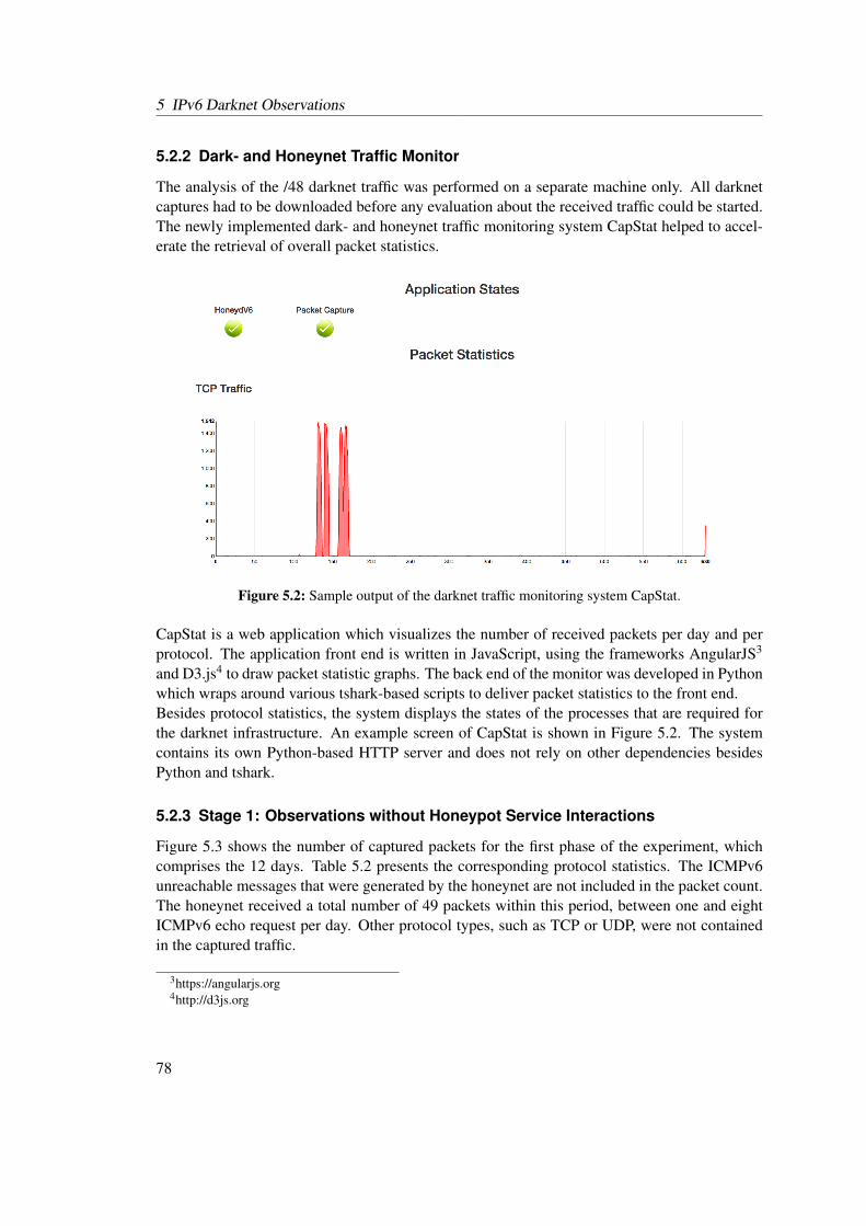
5 IPv6 Darknet Observations
5.2.2 Dark- and Honeynet Traffic Monitor
The analysis of the /48 darknet traffic was performed on a separate machine only. All darknetcaptures had to be downloaded before any evaluation about the received traffic could be started.The newly implemented dark- and honeynet traffic monitoring system CapStat helped to accel-erate the retrieval of overall packet statistics.
Figure 5.2: Sample output of the darknet traffic monitoring system CapStat.
CapStat is a web application which visualizes the number of received packets per day and perprotocol. The application front end is written in JavaScript, using the frameworks AngularJS3
and D3.js4 to draw packet statistic graphs. The back end of the monitor was developed in Pythonwhich wraps around various tshark-based scripts to deliver packet statistics to the front end.Besides protocol statistics, the system displays the states of the processes that are required forthe darknet infrastructure. An example screen of CapStat is shown in Figure 5.2. The systemcontains its own Python-based HTTP server and does not rely on other dependencies besidesPython and tshark.
5.2.3 Stage 1: Observations without Honeypot Service Interactions
Figure 5.3 shows the number of captured packets for the first phase of the experiment, whichcomprises the 12 days. Table 5.2 presents the corresponding protocol statistics. The ICMPv6unreachable messages that were generated by the honeynet are not included in the packet count.The honeynet received a total number of 49 packets within this period, between one and eightICMPv6 echo request per day. Other protocol types, such as TCP or UDP, were not containedin the captured traffic.
3https://angularjs.org4http://d3js.org
78
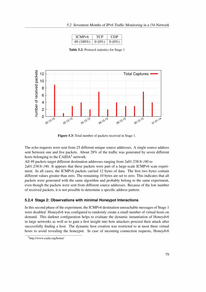
5.2 Seventeen Months of IPv6 Traffic Monitoring in a /34-Network
ICMPv6 TCP UDP49 (100%) 0 (0%) 0 (0%)
Table 5.2: Protocol statistics for Stage 1
0
2
4
6
8
10
12
20.12.13
22.12.13
24.12.13
26.12.13
28.12.13
30.12.13
01.01.14
num
ber
of re
ceiv
ed p
ackets
Total Captures
Figure 5.3: Total number of packets received in Stage 1.
The echo requests were sent from 25 different unique source addresses. A single source addresssent between one and five packets. About 28% of the traffic was generated by seven differenthosts belonging to the CAIDA5 network.All 49 packets target different destination addresses ranging from 2a01:238:8::/40 to2a01:238:b::/40. It appears that these packets were part of a large-scale ICMPv6 scan experi-ment. In all cases, the ICMPv6 packets carried 12 bytes of data. The first two bytes containdifferent values greater than zero. The remaining 10 bytes are set to zero. This indicates that allpackets were generated with the same algorithm and probably belong to the same experiment,even though the packets were sent from different source addresses. Because of the low numberof received packets, it is not possible to determine a specific address pattern.
5.2.4 Stage 2: Observations with minimal Honeypot Interactions
In this second phase of the experiment, the ICMPv6 destination unreachable messages of Stage 1were disabled. Honeydv6 was configured to randomly create a small number of virtual hosts ondemand. This darknet configuration helps to evaluate the dynamic instantiation of Honeydv6in large networks as well as to gain a first insight into how attackers proceed their attack aftersuccessfully finding a host. The dynamic host creation was restricted to at most three virtualhosts to avoid revealing the honeypot. In case of incoming connection requests, Honeydv6
5http://www.caida.org/home/
79
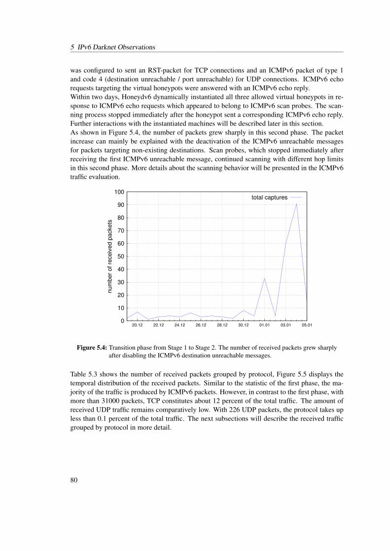
5 IPv6 Darknet Observations
was configured to sent an RST-packet for TCP connections and an ICMPv6 packet of type 1and code 4 (destination unreachable / port unreachable) for UDP connections. ICMPv6 echorequests targeting the virtual honeypots were answered with an ICMPv6 echo reply.Within two days, Honeydv6 dynamically instantiated all three allowed virtual honeypots in re-sponse to ICMPv6 echo requests which appeared to belong to ICMPv6 scan probes. The scan-ning process stopped immediately after the honeypot sent a corresponding ICMPv6 echo reply.Further interactions with the instantiated machines will be described later in this section.As shown in Figure 5.4, the number of packets grew sharply in this second phase. The packetincrease can mainly be explained with the deactivation of the ICMPv6 unreachable messagesfor packets targeting non-existing destinations. Scan probes, which stopped immediately afterreceiving the first ICMPv6 unreachable message, continued scanning with different hop limitsin this second phase. More details about the scanning behavior will be presented in the ICMPv6traffic evaluation.
0
10
20
30
40
50
60
70
80
90
100
20.12 22.12 24.12 26.12 28.12 30.12 01.01 03.01 05.01
num
ber
of re
ceiv
ed p
ackets
total captures
Figure 5.4: Transition phase from Stage 1 to Stage 2. The number of received packets grew sharplyafter disabling the ICMPv6 destination unreachable messages.
Table 5.3 shows the number of received packets grouped by protocol, Figure 5.5 displays thetemporal distribution of the received packets. Similar to the statistic of the first phase, the ma-jority of the traffic is produced by ICMPv6 packets. However, in contrast to the first phase, withmore than 31000 packets, TCP constitutes about 12 percent of the total traffic. The amount ofreceived UDP traffic remains comparatively low. With 226 UDP packets, the protocol takes upless than 0.1 percent of the total traffic. The next subsections will describe the received trafficgrouped by protocol in more detail.
80
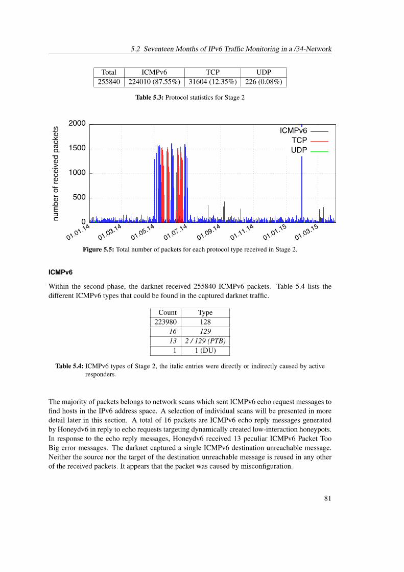
5.2 Seventeen Months of IPv6 Traffic Monitoring in a /34-Network
Total ICMPv6 TCP UDP255840 224010 (87.55%) 31604 (12.35%) 226 (0.08%)
Table 5.3: Protocol statistics for Stage 2
��
����
�����
�����
�����
��������
��������
��������
��������
��������
��������
��������
��������
�������������������������� ������
���
���
Figure 5.5: Total number of packets for each protocol type received in Stage 2.
ICMPv6
Within the second phase, the darknet received 255840 ICMPv6 packets. Table 5.4 lists thedifferent ICMPv6 types that could be found in the captured darknet traffic.
Count Type223980 128
16 12913 2 / 129 (PTB)1 1 (DU)
Table 5.4: ICMPv6 types of Stage 2, the italic entries were directly or indirectly caused by activeresponders.
The majority of packets belongs to network scans which sent ICMPv6 echo request messages tofind hosts in the IPv6 address space. A selection of individual scans will be presented in moredetail later in this section. A total of 16 packets are ICMPv6 echo reply messages generatedby Honeydv6 in reply to echo requests targeting dynamically created low-interaction honeypots.In response to the echo reply messages, Honeydv6 received 13 peculiar ICMPv6 Packet TooBig error messages. The darknet captured a single ICMPv6 destination unreachable message.Neither the source nor the target of the destination unreachable message is reused in any otherof the received packets. It appears that the packet was caused by misconfiguration.
81
5 IPv6 Darknet Observations
Table 5.5 lists the top ten sources that generated a large number of ICMPv6 packets.
Packet count Source14994 2a00:1398:200:0:886b:f3ff:fe66:2b6e7844 2001:4b20:ca1d::e47721 2001:630:212:225:225:90ff:fe0c:45a67685 2001:470:0:12d::27620 2001:388:1:180f:20e:cff:fe4b:fb757600 2001:468:d01:103::80df:9d087514 2001:610:1:80bb:202:a5ff:fee7:227a7370 2607:f380:a44:4::47353 2a00:1398:200:0:84:90ff:fe69:7c3c7250 2001:388:1:5001:21c:c0ff:fea2:4a3a
Table 5.5: Top ten ICMPv6 sources
All packets generated by the sources in Table 5.5 could clearly be identified as ICMPv6 echorequest based scanning probes. For each source address, the target address space, the scanpattern as well as the time span in which the scan was executed was analyzed. Furthermore, theorganization that stays behind a network scan was identified, if possible, using the linux tools digfor reverse DNS lookups and whois. The online service ultratools6 was used to retrieve furtherinformation about the responsible Autonomous System (AS).The target address space of each scan was visualized by converting each contacted address intoa 128-bit integer value that could be depicted on a gnuplot7 diagram. The conversion fromIPv6 address to number was achieved with the help of a python script that utilizes only pythonstandard libraries. First plotting attempts revealed that the applied gnuplot version 4.6.6 is notable to plot the large 128-bit integer values. For this reason, a newly developed script downsizesthe generated 128-bit values without destroying the proportions. After downsizing all addresses,the lowest scanned address equals zero. All other address values in the visualization describethe distance between the corresponding address and the lowest scanned address.
ICMPv6 top source I By far most of the received ICMPv6 packets were generated by a sourcethat refers to an AS registered by the Karlsruhe Institute of Technology. Multiple echo requestmessage based network scans sent 14994 packets to 4352 unique destinations. Except two ofthe received packets, all packets arrived with a hop limit value of 57. Noticeable is the factthat all scans tried to contact only low-byte addresses ending with ::1 in various subnets. Thesame source generated a large number of TCP packets as shown in the TCP section. Figure 5.6visualizes the scanned address space.
6https://www.ultratools.com/tools/asnInfo7http://www.gnuplot.info
82
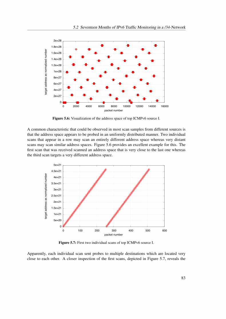
5.2 Seventeen Months of IPv6 Traffic Monitoring in a /34-Network
��
������
������
������
������
������
��������
��������
��������
��������
������
�� ����� ����� ����� ����� ������ ������ ������ ������
�����������������������������������
�������������
Figure 5.6: Visualization of the address space of top ICMPv6 source I.
A common characteristic that could be observed in most scan samples from different sources isthat the address space appears to be probed in an uniformly distributed manner. Two individualscans that appear in a row may scan an entirely different address space whereas very distantscans may scan similar address spaces. Figure 5.6 provides an excellent example for this. Thefirst scan that was received scanned an address space that is very close to the last one whereasthe third scan targets a very different address space.
��
������
������
��������
������
��������
������
��������
������
��������
������
�� ���� ���� ���� ���� ���� ����
�����������������������������������
�������������
Figure 5.7: First two individual scans of top ICMPv6 source I.
Apparently, each individual scan sent probes to multiple destinations which are located veryclose to each other. A closer inspection of the first scans, depicted in Figure 5.7, reveals the
83
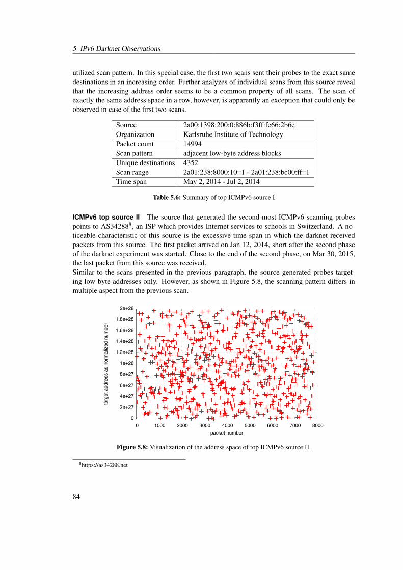
5 IPv6 Darknet Observations
utilized scan pattern. In this special case, the first two scans sent their probes to the exact samedestinations in an increasing order. Further analyzes of individual scans from this source revealthat the increasing address order seems to be a common property of all scans. The scan ofexactly the same address space in a row, however, is apparently an exception that could only beobserved in case of the first two scans.
Source 2a00:1398:200:0:886b:f3ff:fe66:2b6eOrganization Karlsruhe Institute of TechnologyPacket count 14994Scan pattern adjacent low-byte address blocksUnique destinations 4352Scan range 2a01:238:8000:10::1 - 2a01:238:bc00:ff::1Time span May 2, 2014 - Jul 2, 2014
Table 5.6: Summary of top ICMPv6 source I
ICMPv6 top source II The source that generated the second most ICMPv6 scanning probespoints to AS342888, an ISP which provides Internet services to schools in Switzerland. A no-ticeable characteristic of this source is the excessive time span in which the darknet receivedpackets from this source. The first packet arrived on Jan 12, 2014, short after the second phaseof the darknet experiment was started. Close to the end of the second phase, on Mar 30, 2015,the last packet from this source was received.Similar to the scans presented in the previous paragraph, the source generated probes target-ing low-byte addresses only. However, as shown in Figure 5.8, the scanning pattern differs inmultiple aspect from the previous scan.
��
������
������
������
������
������
��������
��������
��������
��������
������
�� ����� ����� ����� ����� ����� ����� ����� �����
�����������������������������������
�������������
Figure 5.8: Visualization of the address space of top ICMPv6 source II.
8https://as34288.net
84
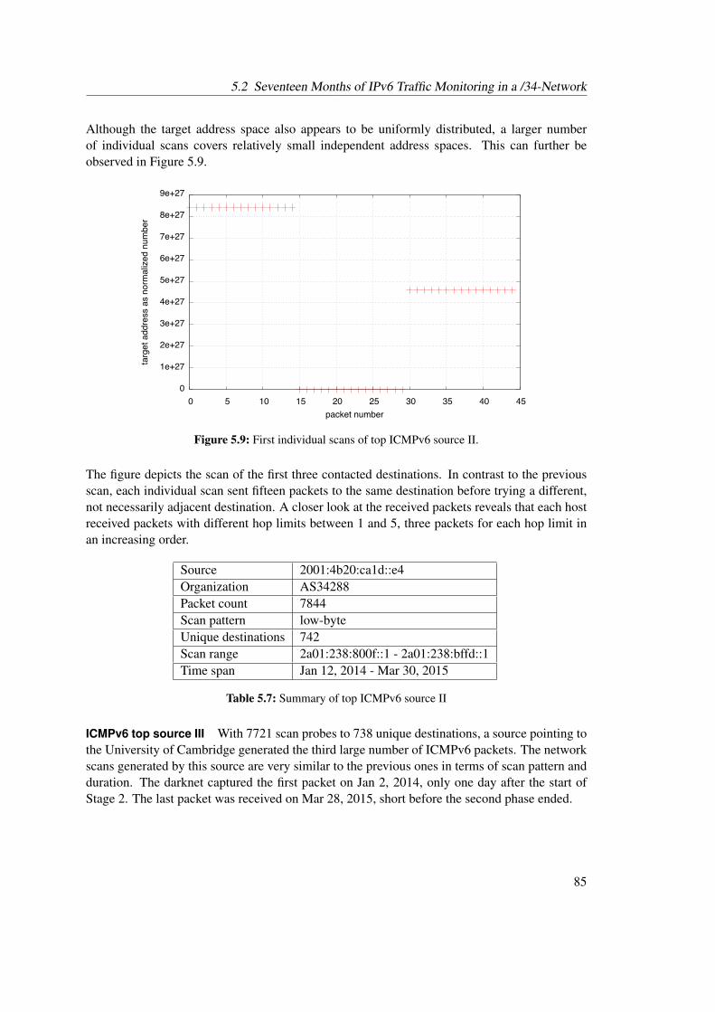
5.2 Seventeen Months of IPv6 Traffic Monitoring in a /34-Network
Although the target address space also appears to be uniformly distributed, a larger numberof individual scans covers relatively small independent address spaces. This can further beobserved in Figure 5.9.
��
������
������
������
������
������
������
������
������
������
�� �� ��� ��� ��� ��� ��� ��� ��� ���
�����������������������������������
�������������
Figure 5.9: First individual scans of top ICMPv6 source II.
The figure depicts the scan of the first three contacted destinations. In contrast to the previousscan, each individual scan sent fifteen packets to the same destination before trying a different,not necessarily adjacent destination. A closer look at the received packets reveals that each hostreceived packets with different hop limits between 1 and 5, three packets for each hop limit inan increasing order.
Source 2001:4b20:ca1d::e4Organization AS34288Packet count 7844Scan pattern low-byteUnique destinations 742Scan range 2a01:238:800f::1 - 2a01:238:bffd::1Time span Jan 12, 2014 - Mar 30, 2015
Table 5.7: Summary of top ICMPv6 source II
ICMPv6 top source III With 7721 scan probes to 738 unique destinations, a source pointing tothe University of Cambridge generated the third large number of ICMPv6 packets. The networkscans generated by this source are very similar to the previous ones in terms of scan pattern andduration. The darknet captured the first packet on Jan 2, 2014, only one day after the start ofStage 2. The last packet was received on Mar 28, 2015, short before the second phase ended.
85
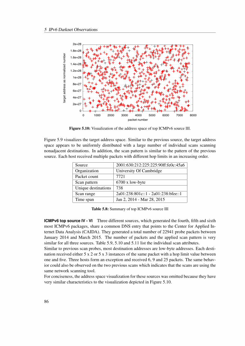
5 IPv6 Darknet Observations
��
������
������
������
������
������
��������
��������
��������
��������
������
�� ����� ����� ����� ����� ����� ����� ����� �����
�����������������������������������
�������������
Figure 5.10: Visualization of the address space of top ICMPv6 source III.
Figure 5.9 visualizes the target address space. Similar to the previous source, the target addressspace appears to be uniformly distributed with a large number of individual scans scanningnonadjacent destinations. In addition, the scan pattern is similar to the pattern of the previoussource. Each host received multiple packets with different hop limits in an increasing order.
Source 2001:630:212:225:225:90ff:fe0c:45a6Organization University Of CambridgePacket count 7721Scan pattern 6700 x low-byteUnique destinations 738Scan range 2a01:238:801c::1 - 2a01:238:bfee::1Time span Jan 2, 2014 - Mar 28, 2015
Table 5.8: Summary of top ICMPv6 source III
ICMPv6 top source IV - VI Three different sources, which generated the fourth, fifth and sixthmost ICMPv6 packages, share a common DNS entry that points to the Center for Applied In-ternet Data Analysis (CAIDA). They generated a total number of 22941 probe packets betweenJanuary 2014 and March 2015. The number of packets and the applied scan pattern is verysimilar for all three sources. Table 5.9, 5.10 and 5.11 list the individual scan attributes.Similar to previous scan probes, most destination addresses are low-byte addresses. Each desti-nation received either 5 x 2 or 5 x 3 instances of the same packet with a hop limit value betweenone and five. Three hosts form an exception and received 6, 9 and 25 packets. The same behav-ior could also be observed on the two previous scans which indicates that the scans are using thesame network scanning tool.For conciseness, the address space visualization for these sources was omitted because they havevery similar characteristics to the visualization depicted in Figure 5.10.
86

5.2 Seventeen Months of IPv6 Traffic Monitoring in a /34-Network
Source 2001:470:0:12d::2Organization Center for Applied Internet Data Analysis (CAIDA)Packet count 7721Scan pattern 6770 x low-byteUnique destinations 737Scan range 2a01:238:8000::1 - 2a01:238:bfe5::1Time span Jan 4, 2014 - Mar 30, 2015
Table 5.9: Summary of top ICMPv6 source IV
Source 2001:388:1:180f:20e:cff:fe4b:fb75Organization Center for Applied Internet Data Analysis (CAIDA)Packet count 7620Scan pattern 6840 x low-byteUnique destinations 735Scan range 2a01:238:8003::1 - 2a01:238:bff1::1Time span Feb 7, 2014 - Mar 4, 2015
Table 5.10: Summary of top ICMPv6 source V
Source 2001:468:d01:103::80df:9d08Organization Center for Applied Internet Data Analysis (CAIDA)Packet count 7600Scan pattern 6475 x low-byteUnique destinations 721Scan range 2a01:238:8000::1 - 2a01:238:bffb::1Time span Jan 4, 2014 - Mar 17, 2015
Table 5.11: Summary of top ICMPv6 source VI
ICMPv6 top source VII SURF9, an ICT organization from the Netherlands, generated a totalnumber of 7514 ICMPv6 echo request message-based scan probes. Table 5.12 lists the proper-ties of the network scans. They appear to correlate to the network scans that were conductedby CAIDA. The scans apply the same scan pattern which mostly probe low-byte addresses withdifferent hop limit values.
9https://www.surf.nl
87
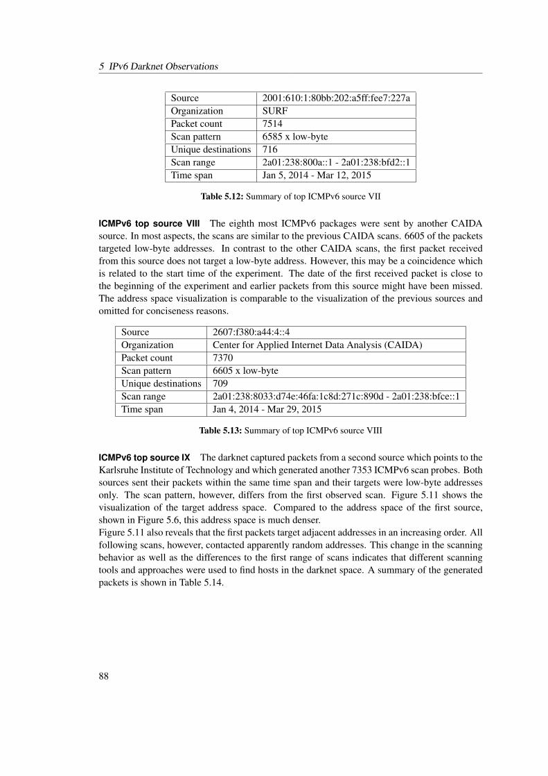
5 IPv6 Darknet Observations
Source 2001:610:1:80bb:202:a5ff:fee7:227aOrganization SURFPacket count 7514Scan pattern 6585 x low-byteUnique destinations 716Scan range 2a01:238:800a::1 - 2a01:238:bfd2::1Time span Jan 5, 2014 - Mar 12, 2015
Table 5.12: Summary of top ICMPv6 source VII
ICMPv6 top source VIII The eighth most ICMPv6 packages were sent by another CAIDAsource. In most aspects, the scans are similar to the previous CAIDA scans. 6605 of the packetstargeted low-byte addresses. In contrast to the other CAIDA scans, the first packet receivedfrom this source does not target a low-byte address. However, this may be a coincidence whichis related to the start time of the experiment. The date of the first received packet is close tothe beginning of the experiment and earlier packets from this source might have been missed.The address space visualization is comparable to the visualization of the previous sources andomitted for conciseness reasons.
Source 2607:f380:a44:4::4Organization Center for Applied Internet Data Analysis (CAIDA)Packet count 7370Scan pattern 6605 x low-byteUnique destinations 709Scan range 2a01:238:8033:d74e:46fa:1c8d:271c:890d - 2a01:238:bfce::1Time span Jan 4, 2014 - Mar 29, 2015
Table 5.13: Summary of top ICMPv6 source VIII
ICMPv6 top source IX The darknet captured packets from a second source which points to theKarlsruhe Institute of Technology and which generated another 7353 ICMPv6 scan probes. Bothsources sent their packets within the same time span and their targets were low-byte addressesonly. The scan pattern, however, differs from the first observed scan. Figure 5.11 shows thevisualization of the target address space. Compared to the address space of the first source,shown in Figure 5.6, this address space is much denser.Figure 5.11 also reveals that the first packets target adjacent addresses in an increasing order. Allfollowing scans, however, contacted apparently random addresses. This change in the scanningbehavior as well as the differences to the first range of scans indicates that different scanningtools and approaches were used to find hosts in the darknet space. A summary of the generatedpackets is shown in Table 5.14.
88
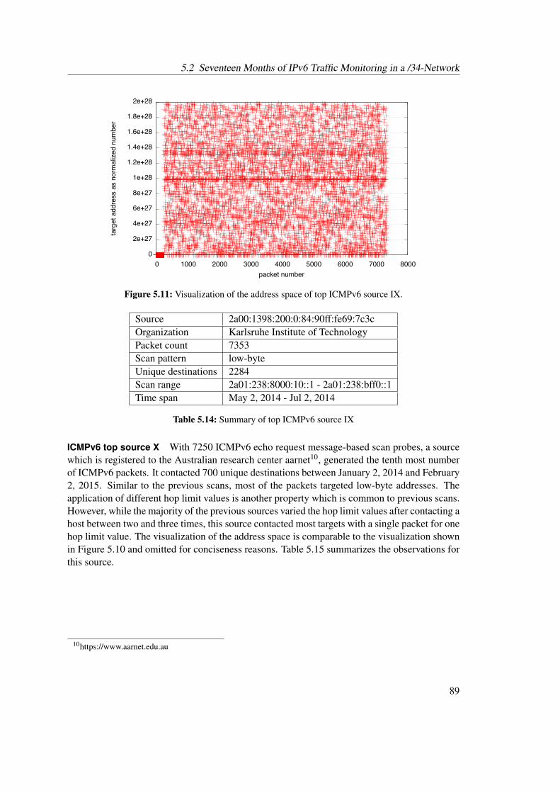
5.2 Seventeen Months of IPv6 Traffic Monitoring in a /34-Network
��
������
������
������
������
������
��������
��������
��������
��������
������
�� ����� ����� ����� ����� ����� ����� ����� �����
�����������������������������������
�������������
Figure 5.11: Visualization of the address space of top ICMPv6 source IX.
Source 2a00:1398:200:0:84:90ff:fe69:7c3cOrganization Karlsruhe Institute of TechnologyPacket count 7353Scan pattern low-byteUnique destinations 2284Scan range 2a01:238:8000:10::1 - 2a01:238:bff0::1Time span May 2, 2014 - Jul 2, 2014
Table 5.14: Summary of top ICMPv6 source IX
ICMPv6 top source X With 7250 ICMPv6 echo request message-based scan probes, a sourcewhich is registered to the Australian research center aarnet10, generated the tenth most numberof ICMPv6 packets. It contacted 700 unique destinations between January 2, 2014 and February2, 2015. Similar to the previous scans, most of the packets targeted low-byte addresses. Theapplication of different hop limit values is another property which is common to previous scans.However, while the majority of the previous sources varied the hop limit values after contacting ahost between two and three times, this source contacted most targets with a single packet for onehop limit value. The visualization of the address space is comparable to the visualization shownin Figure 5.10 and omitted for conciseness reasons. Table 5.15 summarizes the observations forthis source.
10https://www.aarnet.edu.au
89
5 IPv6 Darknet Observations
Source 2001:388:1:5001:21c:c0ff:fea2:4a3aOrganization aarnet - Australia’s National Research and Education NetworkPacket count 7250Scan pattern 6515 x low-byteUnique destinations 700Scan range 2a01:238:8000:10::1 - 2a01:238:bff0::1Time span Jan 2, 2014 - Feb 2, 2015
Table 5.15: Summary of top ICMPv6 source X
Interaction with active responders Stage 2 allowed Honeydv6 to dynamically instantiate atmost three low-interaction hosts. This configuration helped to gain a first insight into how attack-ers proceed their attacks after finding a host. Furthermore, it allowed to conduct a first evaluationof the dynamic low-interaction honeypot instantiation mechanism in large address spaces with-out revealing the honeypot infrastructure. Although the allowed number of dynamic hosts wasstrongly restricted in this second stage, some interesting interactions could be observed.A dynamically instantiated host with the address 2a01:238:82d3:cb86:9e85:2230:865:7b74 re-ceived an ICMPv6 echo request message on January 2, 2014 which was part of the network scanthat is shown in Table 5.8. While other targets of the scan procedure were contacted multipletimes, using different hop limit values, the newly instantiated host was contacted only once.The ICMPv6 echo reply message instantly stopped the interaction with the host. No furtherinteraction with the contacted host could be observed.Another host, with the address 2a01:238:bc98:b172:c16c:1694:436d:e6ee, was dynamically in-stantiated on January 2, 2014. In contrast to the first host, the communication did not stopafter the first interaction. The host received further echo request messages on October 16, 2014,November 7, 2014, March 24, 2015 and March 25, 2015. These echo requests were sent fromdifferent source addresses. The first source points to the domain nps.edu, which belongs tothe Naval Postgraduate School located in the United States11. All further requests to this sourcecame from two different sources that belong to the address space of the German webhosting com-pany Strato, which also provided the darknet space for this experiment. It is not clear whetherthe different sources belong to the same experiment or if they were conducted with the same net-work scanning tool. The probability that this is a coincidence, however, is extremely low. Witha total number of about 30000 unique destinations in Stage 2, only about 1.5∗10−24 percent ofall hosts in the /34 network received a packet. This fact amplifies the argument for a possibleconnection between the different probe packets.The most interesting interaction could be observed between three sources, of which two alsobelong to the Naval Postgraduate School, and a dynamically created Honeydv6 host. On Jan-uary 1, 2014, an ICMPv6 echo request message coming from 2001:d18:1:1:ba27:ebff:fe7a:353caused the instantiation of a new low-interaction host having the apparently random address2a01:238:a446:f445:844:e9be:6dc5:ad21. On October 16, 2014, another source that belongs tothe address space of the Naval Postgraduate School sent an echo request message to the samedestination. The corresponding echo reply message caused an ICMPv6 Packet Too Big error
11http://nps.edu
90
5.2 Seventeen Months of IPv6 Traffic Monitoring in a /34-Network
message. Because an echo reply message only returns the data that was sent by the corre-sponding echo request message, the size of the packet stays unaltered. Hence, an excess of theMaximum Transmission Unit (MTU) can only be explained with a return path that is differentto the original path or the misconfiguration of the target or one of the intermediate hosts. A no-ticeable characteristic of the Packet Too Big message is that it was sent directly from the targethost which means that the Echo Reply could successfully reach its destination. The initial echorequest message had an IPv6 payload length of 1260 bytes which does not include the length ofthe 40-byte IPv6 base header. Hence, the total IPv6 packet size including the base header is 1300bytes which is 20 bytes over the minimum size that each IPv6 host must support [DH98]. AnMTU of 1280 bytes is also defined in the Packet Too Big message. An ICMPv6 error messageof this type carries as much as possible of the message that caused the MTU excess [CDG06].An interesting anomaly of the error message is that its data section contains binary data thatapparently includes a passwd entry for the user nobody in group 9999 instead of the originalmessage. One possible explanation for this behavior is an attack that exploits the faulty process-ing of ICMPv6 error messages. However, no published information about such an attack couldbe found and it is more probable that the payload is caused by flaws in the scanner implemen-tation. A different source which apparently utilized the same scanning methodology and whichalso replied with ICMPv6 Packet Too Big messages contacted the same address in November2014 and March 2015. However, in contrast to the first error messages, the data sections of thesemessages were correct.
TCP
The darknet captured a total number of 31604 TCP packets within the second stage of the ex-periment. Table 5.16 provides a flag statistic over the delivered TCP packets.
Packet count Packet flags31521 SYN27 ACK7 ACK + FIN4 RST17 No flags28 Miscellaneous flag combinations
Table 5.16: TCP packet flags of Stage 2
Only 26 of the 31604 carried an actual payload. Most of the received packets appear to belongto TCP SYN scans. This kind of scan sends TCP packets with activated SYN flags to its targetin order to gain information about available services. If the requested service is available on thetarget machine, then the target continues the TCP handshake with a packet that has the SYN andACK flag set. Otherwise, it signalizes the connection attempt to a closed port with a TCP packethaving the RST flag set. The darknet captured a total number of 31521 of those connectionattempts where the SYN flag is the only set flag.When an attacker forges a connection request using a source address that lies within the dark-net’s address space than the darknet will receive the responses to those packets. In this case, the
91
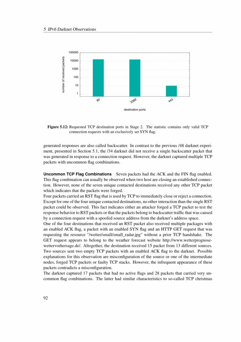
5 IPv6 Darknet Observations
��
���
����
�����
������
�������
������ ��
�
��������������������������
�����������������
Figure 5.12: Requested TCP destination ports in Stage 2. The statistic contains only valid TCPconnection requests with an exclusively set SYN flag.
generated responses are also called backscatter. In contrast to the previous /48 darknet experi-ment, presented in Section 5.1, the /34 darknet did not receive a single backscatter packet thatwas generated in response to a connection request. However, the darknet captured multiple TCPpackets with uncommon flag combinations.
Uncommon TCP Flag Combinations Seven packets had the ACK and the FIN flag enabled.This flag combination can usually be observed when two host are closing an established connec-tion. However, none of the seven unique contacted destinations received any other TCP packetwhich indicates that the packets were forged.Four packets carried an RST flag that is used by TCP to immediately close or reject a connection.Except for one of the four unique contacted destinations, no other interaction than the single RSTpacket could be observed. This fact indicates either an attacker forged a TCP packet to test theresponse behavior to RST packets or that the packets belong to backscatter traffic that was causedby a connection request with a spoofed source address from the darknet’s address space.One of the four destinations that received an RST packet also received multiple packages withan enabled ACK flag, a packet with an enabled SYN flag and an HTTP GET request that wasrequesting the resource "/wetter/small/small_radar.jpg" without a prior TCP handshake. TheGET request appears to belong to the weather forecast website http://www.wetterprognose-wettervorhersage.de/. Altogether, the destination received 15 packet from 13 different sources.Two sources sent two empty TCP packets with an enabled ACK flag to the darknet. Possibleexplanations for this observation are misconfiguration of the source or one of the intermediatenodes, forged TCP packets or faulty TCP stacks. However, the infrequent appearance of thesepackets contradicts a misconfiguration.The darknet captured 17 packets that had no active flags and 28 packets that carried very un-common flag combinations. The latter had similar characteristics to so-called TCP christmas
92
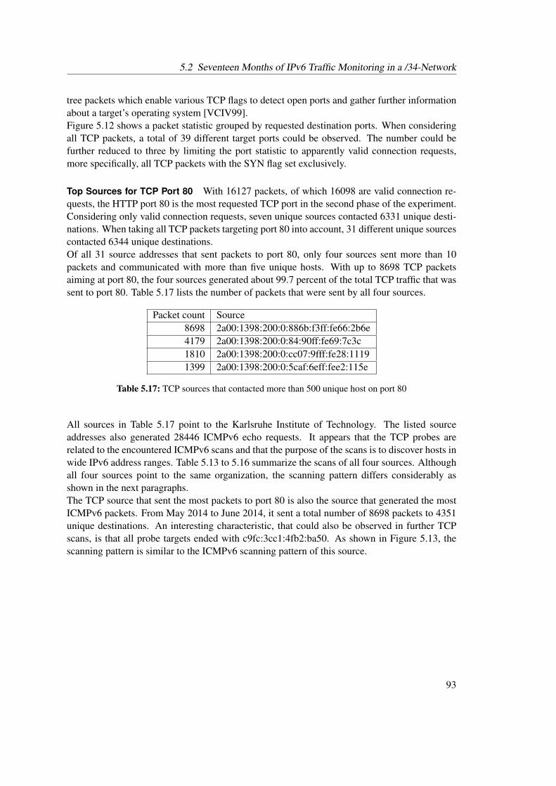
5.2 Seventeen Months of IPv6 Traffic Monitoring in a /34-Network
tree packets which enable various TCP flags to detect open ports and gather further informationabout a target’s operating system [VCIV99].Figure 5.12 shows a packet statistic grouped by requested destination ports. When consideringall TCP packets, a total of 39 different target ports could be observed. The number could befurther reduced to three by limiting the port statistic to apparently valid connection requests,more specifically, all TCP packets with the SYN flag set exclusively.
Top Sources for TCP Port 80 With 16127 packets, of which 16098 are valid connection re-quests, the HTTP port 80 is the most requested TCP port in the second phase of the experiment.Considering only valid connection requests, seven unique sources contacted 6331 unique desti-nations. When taking all TCP packets targeting port 80 into account, 31 different unique sourcescontacted 6344 unique destinations.Of all 31 source addresses that sent packets to port 80, only four sources sent more than 10packets and communicated with more than five unique hosts. With up to 8698 TCP packetsaiming at port 80, the four sources generated about 99.7 percent of the total TCP traffic that wassent to port 80. Table 5.17 lists the number of packets that were sent by all four sources.
Packet count Source8698 2a00:1398:200:0:886b:f3ff:fe66:2b6e4179 2a00:1398:200:0:84:90ff:fe69:7c3c1810 2a00:1398:200:0:cc07:9fff:fe28:11191399 2a00:1398:200:0:5caf:6eff:fee2:115e
Table 5.17: TCP sources that contacted more than 500 unique host on port 80
All sources in Table 5.17 point to the Karlsruhe Institute of Technology. The listed sourceaddresses also generated 28446 ICMPv6 echo requests. It appears that the TCP probes arerelated to the encountered ICMPv6 scans and that the purpose of the scans is to discover hosts inwide IPv6 address ranges. Table 5.13 to 5.16 summarize the scans of all four sources. Althoughall four sources point to the same organization, the scanning pattern differs considerably asshown in the next paragraphs.The TCP source that sent the most packets to port 80 is also the source that generated the mostICMPv6 packets. From May 2014 to June 2014, it sent a total number of 8698 packets to 4351unique destinations. An interesting characteristic, that could also be observed in further TCPscans, is that all probe targets ended with c9fc:3cc1:4fb2:ba50. As shown in Figure 5.13, thescanning pattern is similar to the ICMPv6 scanning pattern of this source.
93
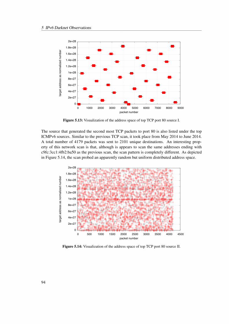
5 IPv6 Darknet Observations
��
������
������
������
������
������
��������
��������
��������
��������
������
�� ����� ����� ����� ����� ����� ����� ����� ����� �����
�����������������������������������
�������������
Figure 5.13: Visualization of the address space of top TCP port 80 source I.
The source that generated the second most TCP packets to port 80 is also listed under the topICMPv6 sources. Similar to the previous TCP scan, it took place from May 2014 to June 2014.A total number of 4179 packets was sent to 2101 unique destinations. An interesting prop-erty of this network scan is that, although is appears to scan the same addresses ending withc9fc:3cc1:4fb2:ba50 as the previous scan, the scan pattern is completely different. As depictedin Figure 5.14, the scan probed an apparently random but uniform distributed address space.
��
������
������
������
������
������
��������
��������
��������
��������
������
�� ���� ����� ����� ����� ����� ����� ����� ����� �����
�����������������������������������
�������������
Figure 5.14: Visualization of the address space of top TCP port 80 source II.
94
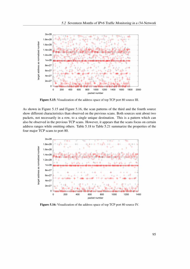
5.2 Seventeen Months of IPv6 Traffic Monitoring in a /34-Network
��
������
������
������
������
������
��������
��������
��������
��������
������
�� ���� ���� ���� ���� ����� ����� ����� ����� ����� �����
�����������������������������������
�������������
Figure 5.15: Visualization of the address space of top TCP port 80 source III.
As shown in Figure 5.15 and Figure 5.16, the scan patterns of the third and the fourth sourceshow different characteristics than observed on the previous scans. Both sources sent about twopackets, not necessarily in a row, to a single unique destination. This is a pattern which canalso be observed in the previous TCP scans. However, it appears that the scans focus on certainaddress ranges while omitting others. Table 5.18 to Table 5.21 summarize the properties of thefour major TCP scans to port 80.
��
������
������
������
������
������
��������
��������
��������
��������
������
�� ���� ���� ���� ���� ����� ����� �����
�����������������������������������
�������������
Figure 5.16: Visualization of the address space of top TCP port 80 source IV.
95

5 IPv6 Darknet Observations
Source 2a00:1398:200:0:886b:f3ff:fe66:2b6eOrganization Karlsruhe Institute of TechnologyPacket count 8698Scan pattern Adjacent address blocks, addresses ending with c9fc:3cc1:4fb2:ba50Unique destinations 4351Scan range 2a01:238:8000:0:c9fc:3cc1:4fb2:ba50 -
2a01:238:bc00:ff:c9fc:3cc1:4fb2:ba50Time span May 24, 2014 - Jun 24, 2014
Table 5.18: Summary of top TCP port 80 source I
Source 2a00:1398:200:0:84:90ff:fe69:7c3cOrganization Karlsruhe Institute of TechnologyPacket count 4179Scan pattern Apparently random addresses ending with c9fc:3cc1:4fb2:ba50Unique destinations 2101Scan range 2a01:238:8000:0:c9fc:3cc1:4fb2:ba50 -
2a01:238:bff0:1:c9fc:3cc1:4fb2:ba50Time span May 24, 2014 - Jun 23, 2014
Table 5.19: Summary of top TCP port 80 source II
Source 2a00:1398:200:0:cc07:9fff:fe28:1119Organization Karlsruhe Institute of TechnologyPacket count 1810Scan pattern Apparently random addresses ending with 0:c9fc:3cc1:4fb2:ba50Unique destinations 911Scan range 2a01:238:8000:0:c9fc:3cc1:4fb2:ba50 -
2a01:238:bfc0:0:c9fc:3cc1:4fb2:ba50Time span May 24, 2014 - Jun 23, 2014
Table 5.20: Summary of top TCP port 80 source III
Source 2a00:1398:200:0:5caf:6eff:fee2:115eOrganization Karlsruhe Institute of TechnologyPacket count 1399Scan pattern Apparently random addresses ending with 0:c9fc:3cc1:4fb2:ba50Unique destinations 706Scan range 2a01:238:8000:0:c9fc:3cc1:4fb2:ba50 -
2a01:238:bfc0:0:c9fc:3cc1:4fb2:ba50Time span May 24, 2014 - Jun 23, 2014
Table 5.21: Summary of top TCP port 80 source IV
96

5.2 Seventeen Months of IPv6 Traffic Monitoring in a /34-Network
Top Sources for TCP Port 3389 A total number of 15413 packets were sent to port 3389,which belongs to Microsoft’s proprietary Remote Desktop Protocol (RDP) [Mic15b]. As shownin Table 5.22, the statistics of port 3389 are very similar to the port 80 statistics.
Packet count Source8341 2a00:1398:200:0:886b:f3ff:fe66:2b6e3972 2a00:1398:200:0:84:90ff:fe69:7c3c1745 2a00:1398:200:0:cc07:9fff:fe28:11191355 2a00:1398:200:0:5caf:6eff:fee2:115e
Table 5.22: TCP sources that contacted more than 500 unique host on port 3389
The sources that generated the most traffic on port 3389 are the same sources that generatedabout 99 percent of the TCP traffic aiming port 80. Between May 14, 2014 and the June 17,2014, the four sources contacted a number of unique hosts on port 3389 that is almost identicalto the number of hosts contacted on port 80. The observed scan patterns of all four sources equaltheir port 80 counterparts. Therefore, the address space visualizations for this port is omitted forreasons of brevity. Table 5.23 to 5.26 summarize the scan observations for all four sources.
Source 2a00:1398:200:0:886b:f3ff:fe66:2b6eOrganization Karlsruhe Institute of TechnologyPacket count 8341Scan pattern Adjacent address blocks of low-byte addressesUnique destinations 4352Scan range 2a01:238:8000:10::1 - 2a01:238:bc00:ff::1Time span May 14, 2014 - Jun 17, 2014
Table 5.23: Summary of top TCP port 3389 source I
Source 2a00:1398:200:0:84:90ff:fe69:7c3cOrganization Karlsruhe Institute of TechnologyPacket count 3972Scan pattern Apparently random low-byte addressesUnique destinations 2094Scan range 2a01:238:8000:10::1 - 2a01:238:bff0::1Time span May 14, 2014 - Jun 17, 2014
Table 5.24: Summary of top TCP port 3389 source II
97
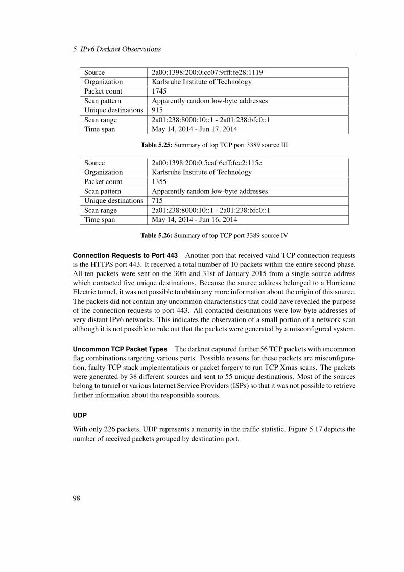
5 IPv6 Darknet Observations
Source 2a00:1398:200:0:cc07:9fff:fe28:1119Organization Karlsruhe Institute of TechnologyPacket count 1745Scan pattern Apparently random low-byte addressesUnique destinations 915Scan range 2a01:238:8000:10::1 - 2a01:238:bfc0::1Time span May 14, 2014 - Jun 17, 2014
Table 5.25: Summary of top TCP port 3389 source III
Source 2a00:1398:200:0:5caf:6eff:fee2:115eOrganization Karlsruhe Institute of TechnologyPacket count 1355Scan pattern Apparently random low-byte addressesUnique destinations 715Scan range 2a01:238:8000:10::1 - 2a01:238:bfc0::1Time span May 14, 2014 - Jun 16, 2014
Table 5.26: Summary of top TCP port 3389 source IV
Connection Requests to Port 443 Another port that received valid TCP connection requestsis the HTTPS port 443. It received a total number of 10 packets within the entire second phase.All ten packets were sent on the 30th and 31st of January 2015 from a single source addresswhich contacted five unique destinations. Because the source address belonged to a HurricaneElectric tunnel, it was not possible to obtain any more information about the origin of this source.The packets did not contain any uncommon characteristics that could have revealed the purposeof the connection requests to port 443. All contacted destinations were low-byte addresses ofvery distant IPv6 networks. This indicates the observation of a small portion of a network scanalthough it is not possible to rule out that the packets were generated by a misconfigured system.
Uncommon TCP Packet Types The darknet captured further 56 TCP packets with uncommonflag combinations targeting various ports. Possible reasons for these packets are misconfigura-tion, faulty TCP stack implementations or packet forgery to run TCP Xmas scans. The packetswere generated by 38 different sources and sent to 55 unique destinations. Most of the sourcesbelong to tunnel or various Internet Service Providers (ISPs) so that it was not possible to retrievefurther information about the responsible sources.
UDP
With only 226 packets, UDP represents a minority in the traffic statistic. Figure 5.17 depicts thenumber of received packets grouped by destination port.
98
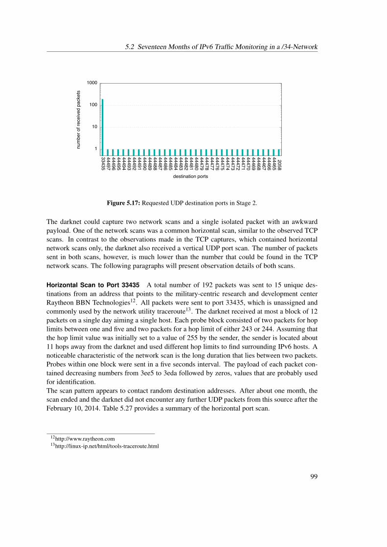
5.2 Seventeen Months of IPv6 Traffic Monitoring in a /34-Network
��
���
����
�����
�����
�����
�����
�����
�����
�����
�����
�����
�����
�����
�����
�����
�����
�����
�����
�����
�����
�����
�����
�����
�����
�����
�����
�����
�����
�����
�����
�����
�����
�����
�����
�����
�����
�����
����
��������������������������
�����������������
Figure 5.17: Requested UDP destination ports in Stage 2.
The darknet could capture two network scans and a single isolated packet with an awkwardpayload. One of the network scans was a common horizontal scan, similar to the observed TCPscans. In contrast to the observations made in the TCP captures, which contained horizontalnetwork scans only, the darknet also received a vertical UDP port scan. The number of packetssent in both scans, however, is much lower than the number that could be found in the TCPnetwork scans. The following paragraphs will present observation details of both scans.
Horizontal Scan to Port 33435 A total number of 192 packets was sent to 15 unique des-tinations from an address that points to the military-centric research and development centerRaytheon BBN Technologies12. All packets were sent to port 33435, which is unassigned andcommonly used by the network utility traceroute13. The darknet received at most a block of 12packets on a single day aiming a single host. Each probe block consisted of two packets for hoplimits between one and five and two packets for a hop limit of either 243 or 244. Assuming thatthe hop limit value was initially set to a value of 255 by the sender, the sender is located about11 hops away from the darknet and used different hop limits to find surrounding IPv6 hosts. Anoticeable characteristic of the network scan is the long duration that lies between two packets.Probes within one block were sent in a five seconds interval. The payload of each packet con-tained decreasing numbers from 3ee5 to 3eda followed by zeros, values that are probably usedfor identification.The scan pattern appears to contact random destination addresses. After about one month, thescan ended and the darknet did not encounter any further UDP packets from this source after theFebruary 10, 2014. Table 5.27 provides a summary of the horizontal port scan.
12http://www.raytheon.com13http://linux-ip.net/html/tools-traceroute.html
99
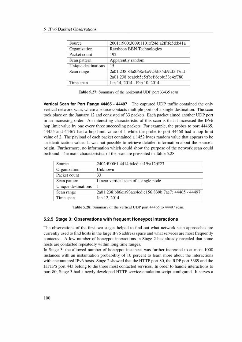
5 IPv6 Darknet Observations
Source 2001:1900:3009:1101:f24d:a2ff:fe5d:b41aOrganization Raytheon BBN TechnologiesPacket count 192Scan pattern Apparently randomUnique destinations 15Scan range 2a01:238:84a8:68c4:a923:b35d:92f5:f7dd -
2a01:238:beab:b5e5:f8cf:6cbb:33e4:f780Time span Jan 14, 2014 - Feb 10, 2014
Table 5.27: Summary of the horizontal UDP port 33435 scan
Vertical Scan for Port Range 44465 - 44497 The captured UDP traffic contained the onlyvertical network scan, where a source contacts multiple ports of a single destination. The scantook place on the January 12 and consisted of 33 packets. Each packet aimed another UDP portin an increasing order. An interesting characteristic of this scan is that it increased the IPv6hop limit value by one every three succeeding packets. For example, the probes to port 44465,44455 and 44467 had a hop limit value of 1 while the probe to port 44468 had a hop limitvalue of 2. The payload of each packet contained a 1452 bytes random value that appears to bean identification value. It was not possible to retrieve detailed information about the source’sorigin. Furthermore, no information which could show the purpose of the network scan couldbe found. The main characteristics of the scan are presented in Table 5.28.
Source 2402:f000:1:4414:64cd:aa19:a12:ff23Organization UnknownPacket count 33Scan pattern Linear vertical scan of a single nodeUnique destinations 1Scan range 2a01:238:b86e:a93a:e4cd:c156:839b:7ae7: 44465 - 44497Time span Jan 12, 2014
Table 5.28: Summary of the vertical UDP port 44465 to 44497 scan.
5.2.5 Stage 3: Observations with frequent Honeypot Interactions
The observations of the first two stages helped to find out what network scan approaches arecurrently used to find hosts in the large IPv6 address space and what services are most frequentlycontacted. A low number of honeypot interactions in Stage 2 has already revealed that somehosts are contacted repeatedly within long time ranges.In Stage 3, the allowed number of honeypot instances was further increased to at most 1000instances with an instantiation probability of 10 percent to learn more about the interactionswith encountered IPv6 hosts. Stage 2 showed that the HTTP port 80, the RDP port 3389 and theHTTPS port 443 belong to the three most contacted services. In order to handle interactions toport 80, Stage 3 had a newly developed HTTP service emulation script configured. It serves a
100
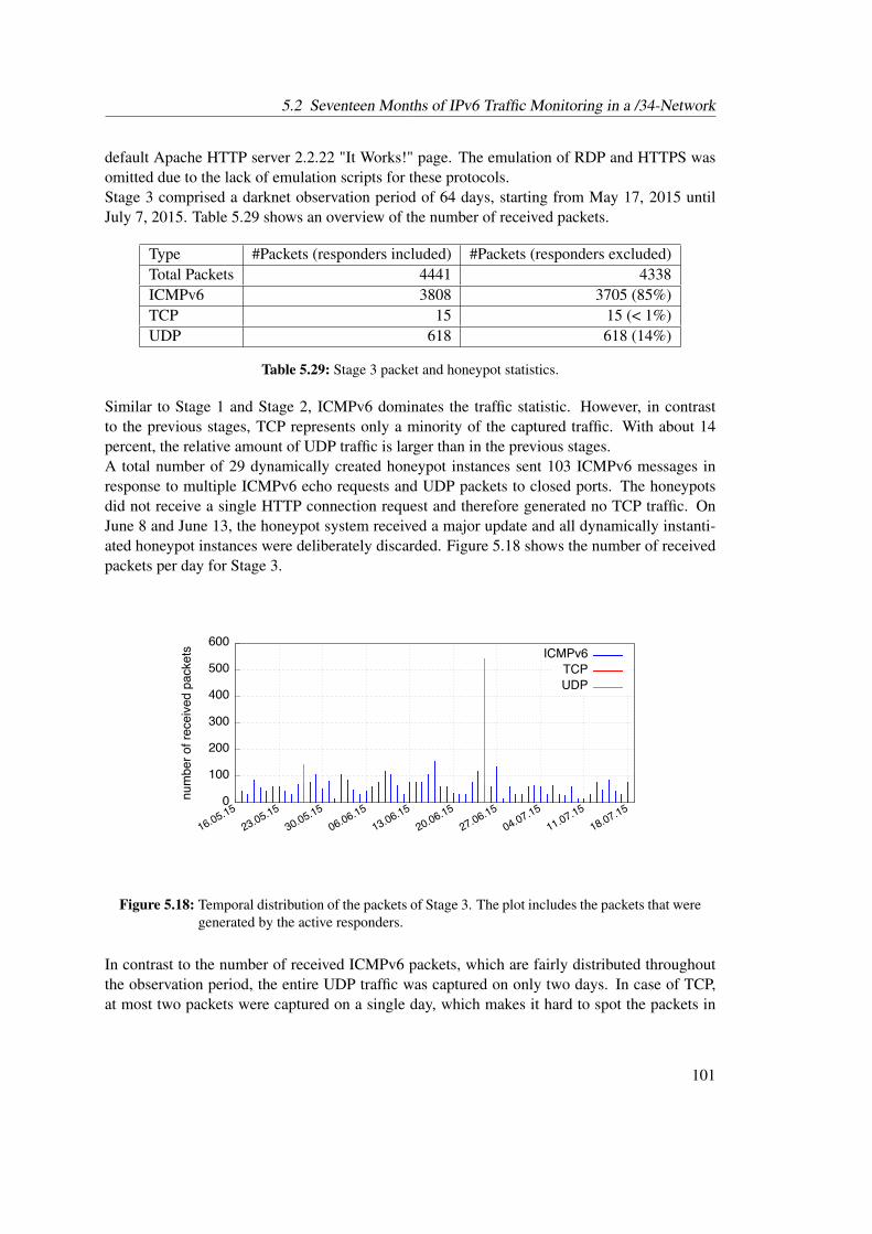
5.2 Seventeen Months of IPv6 Traffic Monitoring in a /34-Network
default Apache HTTP server 2.2.22 "It Works!" page. The emulation of RDP and HTTPS wasomitted due to the lack of emulation scripts for these protocols.Stage 3 comprised a darknet observation period of 64 days, starting from May 17, 2015 untilJuly 7, 2015. Table 5.29 shows an overview of the number of received packets.
Type #Packets (responders included) #Packets (responders excluded)Total Packets 4441 4338ICMPv6 3808 3705 (85%)TCP 15 15 (< 1%)UDP 618 618 (14%)
Table 5.29: Stage 3 packet and honeypot statistics.
Similar to Stage 1 and Stage 2, ICMPv6 dominates the traffic statistic. However, in contrastto the previous stages, TCP represents only a minority of the captured traffic. With about 14percent, the relative amount of UDP traffic is larger than in the previous stages.A total number of 29 dynamically created honeypot instances sent 103 ICMPv6 messages inresponse to multiple ICMPv6 echo requests and UDP packets to closed ports. The honeypotsdid not receive a single HTTP connection request and therefore generated no TCP traffic. OnJune 8 and June 13, the honeypot system received a major update and all dynamically instanti-ated honeypot instances were deliberately discarded. Figure 5.18 shows the number of receivedpackets per day for Stage 3.
��
����
����
����
����
����
����
��������
��������
��������
��������
��������
��������
��������
��������
��������
��������
�������������������������� ������
���
���
Figure 5.18: Temporal distribution of the packets of Stage 3. The plot includes the packets that weregenerated by the active responders.
In contrast to the number of received ICMPv6 packets, which are fairly distributed throughoutthe observation period, the entire UDP traffic was captured on only two days. In case of TCP,at most two packets were captured on a single day, which makes it hard to spot the packets in
101
5 IPv6 Darknet Observations
the visualization. The following subsections present the analysis results for all protocol typesobserved in Stage 3 individually.
ICMPv6
With more than 3800 packets, ICMPv6 represents the majority of the captured traffic. A totalnumber of 52 unique sources sent ICMPv6 messages to 257 different destinations. All packetsexcept one were of type 128, which is a common IPv6 echo request message [CDG06]. As inthe second stage, the darknet captured a large number of ICMPv6 echo request message-basednetwork scans. Although the top sources differ from the sources that were observed within Stage2, no new and more sophisticated scan patterns could be detected. Therefore, a detailed analysisof all patterns and their sources is not included in this section for conciseness reasons.The echo requests caused the dynamic instantiation of 24 honeypot instances. Altogether, thecreated honeypot instances sent 35 ICMPv6 echo reply messages in response to echo requests.Of all 24 dynamically created honeypot instances, 23 received only a single echo requests andtherefore generated only a single response.A single honeypot instance with the address 2a01:238:8b6f:b9c8:8818:e646:a503:c244 seemedto have drawn special interest. It sent 12 echo reply messages in response to 12 echo requestmessages, all coming from different sources. The destination was initially contacted on May26 and received further echo requests on May 27 and May 30, 2015. Although most of thesources point to Raytheon BBN Technologies, some of the sources belonged to very differentsubnets and were registered to various institutions and organizations. This included addresseswhich were registered to wide ranging sources, such as the Russian hardware shop FIRSTVDS14
or the Australian hosting company Crucial15. The data section of all requests starts with theASCII string "Internet Measurement - Session ID", which reveals that the probe packets belongto a large-scale Internet measurement. A noticeable characteristic of this measurement is thatit seems to utilize a shared state about contacted hosts throughout the different sources. Theaddress of the instantiated honeypot has a random appearance and it can therefore be ruled outthat this address was contacted multiple times by coincidence. On June 8, 2015, the sourcewas removed from the honeypot configuration within the scope of a honeypot update. It wasdeliberately not reconfigured to observe how the measurement reacts to destinations that havebecome unavailable. The destination received two more echo requests from Raytheon BBNTechnologies on June 10 and July 10, 2015. The received echo requests, however, differed inmany aspects from the earlier received requests. Both requests came in two IPv6 fragments andcontained, when assembled, an ICMPv6 echo request data field of 1500 bytes. In contrast tothe previously received packets the payload did not indicate an Internet measurement and onlycontained 1500 times the value 0x6f. A possible goal of these requests may be the observationof fragmentation behavior. However, because this source did not receive any further packets, itis not possible to determine the exact purpose of the experiment.A conspicuous packet that was captured by the darknet is a single ICMPv6 message of type 4 andcode 1, a type which is used to signalize the reception of an unrecognized header type [CDG06].
14http://firstvds.ru15https://www.crucial.com.au
102
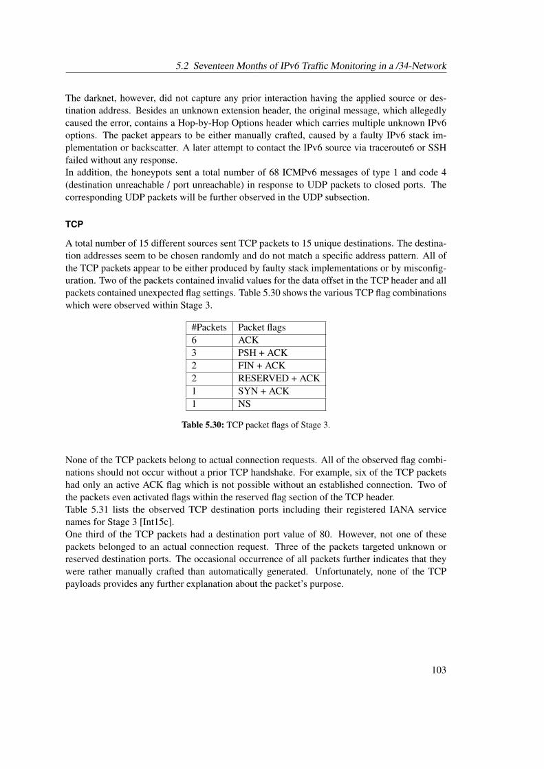
5.2 Seventeen Months of IPv6 Traffic Monitoring in a /34-Network
The darknet, however, did not capture any prior interaction having the applied source or des-tination address. Besides an unknown extension header, the original message, which allegedlycaused the error, contains a Hop-by-Hop Options header which carries multiple unknown IPv6options. The packet appears to be either manually crafted, caused by a faulty IPv6 stack im-plementation or backscatter. A later attempt to contact the IPv6 source via traceroute6 or SSHfailed without any response.In addition, the honeypots sent a total number of 68 ICMPv6 messages of type 1 and code 4(destination unreachable / port unreachable) in response to UDP packets to closed ports. Thecorresponding UDP packets will be further observed in the UDP subsection.
TCP
A total number of 15 different sources sent TCP packets to 15 unique destinations. The destina-tion addresses seem to be chosen randomly and do not match a specific address pattern. All ofthe TCP packets appear to be either produced by faulty stack implementations or by misconfig-uration. Two of the packets contained invalid values for the data offset in the TCP header and allpackets contained unexpected flag settings. Table 5.30 shows the various TCP flag combinationswhich were observed within Stage 3.
#Packets Packet flags6 ACK3 PSH + ACK2 FIN + ACK2 RESERVED + ACK1 SYN + ACK1 NS
Table 5.30: TCP packet flags of Stage 3.
None of the TCP packets belong to actual connection requests. All of the observed flag combi-nations should not occur without a prior TCP handshake. For example, six of the TCP packetshad only an active ACK flag which is not possible without an established connection. Two ofthe packets even activated flags within the reserved flag section of the TCP header.Table 5.31 lists the observed TCP destination ports including their registered IANA servicenames for Stage 3 [Int15c].One third of the TCP packets had a destination port value of 80. However, not one of thesepackets belonged to an actual connection request. Three of the packets targeted unknown orreserved destination ports. The occasional occurrence of all packets further indicates that theywere rather manually crafted than automatically generated. Unfortunately, none of the TCPpayloads provides any further explanation about the packet’s purpose.
103
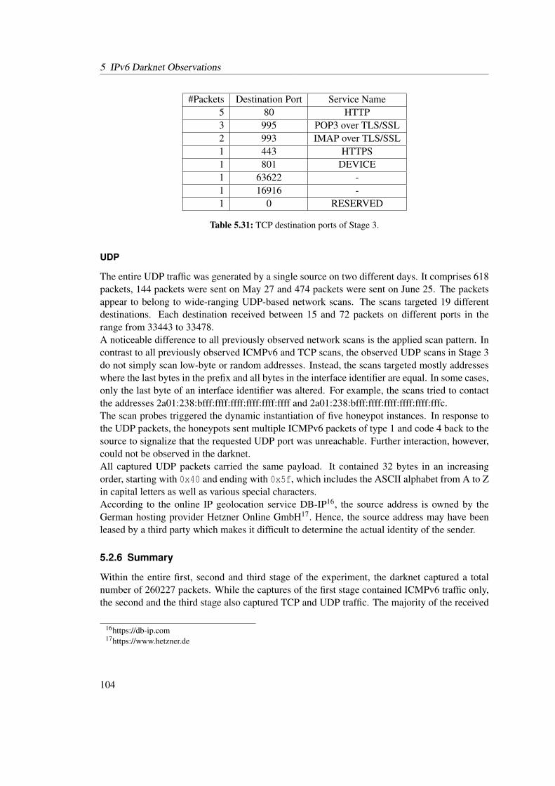
5 IPv6 Darknet Observations
#Packets Destination Port Service Name5 80 HTTP3 995 POP3 over TLS/SSL2 993 IMAP over TLS/SSL1 443 HTTPS1 801 DEVICE1 63622 -1 16916 -1 0 RESERVED
Table 5.31: TCP destination ports of Stage 3.
UDP
The entire UDP traffic was generated by a single source on two different days. It comprises 618packets, 144 packets were sent on May 27 and 474 packets were sent on June 25. The packetsappear to belong to wide-ranging UDP-based network scans. The scans targeted 19 differentdestinations. Each destination received between 15 and 72 packets on different ports in therange from 33443 to 33478.A noticeable difference to all previously observed network scans is the applied scan pattern. Incontrast to all previously observed ICMPv6 and TCP scans, the observed UDP scans in Stage 3do not simply scan low-byte or random addresses. Instead, the scans targeted mostly addresseswhere the last bytes in the prefix and all bytes in the interface identifier are equal. In some cases,only the last byte of an interface identifier was altered. For example, the scans tried to contactthe addresses 2a01:238:bfff:ffff:ffff:ffff:ffff:ffff and 2a01:238:bfff:ffff:ffff:ffff:ffff:fffc.The scan probes triggered the dynamic instantiation of five honeypot instances. In response tothe UDP packets, the honeypots sent multiple ICMPv6 packets of type 1 and code 4 back to thesource to signalize that the requested UDP port was unreachable. Further interaction, however,could not be observed in the darknet.All captured UDP packets carried the same payload. It contained 32 bytes in an increasingorder, starting with 0x40 and ending with 0x5f, which includes the ASCII alphabet from A to Zin capital letters as well as various special characters.According to the online IP geolocation service DB-IP16, the source address is owned by theGerman hosting provider Hetzner Online GmbH17. Hence, the source address may have beenleased by a third party which makes it difficult to determine the actual identity of the sender.
5.2.6 Summary
Within the entire first, second and third stage of the experiment, the darknet captured a totalnumber of 260227 packets. While the captures of the first stage contained ICMPv6 traffic only,the second and the third stage also captured TCP and UDP traffic. The majority of the received
16https://db-ip.com17https://www.hetzner.de
104
5.2 Seventeen Months of IPv6 Traffic Monitoring in a /34-Network
packets belongs to large horizontal ICMPv6 echo request message-based network scans. It ap-pears that most of the scans are conducted by universities or other research institutions. Thescanning methodology differs between multiple scans although some sources seem to apply thesame scanning pattern and even contact the same sources. A majority of the ICMPv6-basednetwork scans contacted only low-byte addresses in various, not necessarily adjacent networks.Four sources, which point to the Karlsruhe Institute of Technology and which generated largeICMPv6 echo request message-based network scans, were also responsible for the majority ofthe TCP traffic. Valid connection requests to HTTP, HTTPS and Microsoft’s RDP ports couldbe observed as part of large TCP SYN scans.UDP traffic represents a minority in the captures. However, the darknet monitor captured thefirst vertical scan in the UDP traffic and observed new scanning methodologies which search forcertain address patterns only. A common property of all encountered network scans is that theycontact wide-ranging and mostly random and unpredictable destinations.For all three protocol types, the darknet captured scattered packets with uncommon properties,e.g. invalid TCP flag combinations or invalid ICMPv6 payloads. It appears that most of thesepackets are caused by misconfigurations or faulty IPv6/TCP stack implementations. It is alsopossible, that some of the various invalid TCP packets belonged to TCP Xmas scans.Honeydv6 has proven to be a useful tool for the evaluation of interactions which take placewhen an attacker has found a host in the IPv6 address space. The dynamic host instantiation ofHoneydv6 could be used to reveal that encountered hosts are requested repeatedly over a periodof time. However, in many cases, network scans stopped immediately after receiving the firstresponse. The darknet captured packets of apparently faulty network scanner implementationswhich sent contents of a passwd file in response to ICMPv6 echo reply messages that weregenerated by Honeydv6.It can be concluded that the IPv6 address space is currently mostly free of threats especiallycompared the to threat level of IPv4 networks. Although the darknet received more packets thananticipated, only about 1.5∗10−24 percent of all hosts in the /34 address space were contacted.
105

5 IPv6 Darknet Observations
106

6 Hyhoneydv6 - A hybrid IPv6-HoneynetArchitecture
The darknet results, presented in the previous chapter, have shown that attackers apply wide-ranging network scans to mostly unpredictable destination addresses. Some of the scans targetedprotocols that can not be simulated with Honeydv6. One example is Microsoft’s proprietaryRemote Desktop Protocol [Mic15b], which was a target of large-scale TCP SYN scans.Honeydv6 is based on the official IPv4 version 1.5c of Honeyd and therefore provides a frame-work for service scripts instead of actually simulating services itself. In order to simulate net-works services, such as SNMP or HTTP, the corresponding service emulation scripts have tobe developed. There is a number of already developed service scripts available and linked onthe official Honeyd website1. However, the emulation capabilities of these scripts are often lim-ited to a certain granularity and in many cases, modification of these scripts is needed to avoidrevealing the honeypot.In contrast to low-interaction honeypots, high-interaction honeypots provide actual serviceswhich, in most cases, do not need any modification and which are harder to detect for an attacker.However, compared to most available low-interaction honeypot solutions, high-interaction hon-eypots have higher performance requirements and provide less flexibility. As explained in sec-tion 4.4, the huge address IPv6 space requires new architectural honeypot approaches whichenable attackers to find targets in a honeynet. It is technically not feasible to statically installa sufficient amount of high-interaction honeypots to cover whole IPv6 networks. The low-interaction honeypot Honeydv6 implements a dynamic instantiation mechanism to handle largeIPv6 address spaces. A comparable solution for high-interaction honeypots, however, is not yetavailable.This chapter presents a hybrid honeypot architecture that combines low- and high-interactionhoneypots to allow the observation of complex attacks in IPv6 networks. The design of thearchitecture was preceded by the definition of various requirements that should be fulfilled byan IPv6 honeypot architecture to be successful. These requirement are presented in the followingsection.
6.1 IPv6 Honeypot Requirements
This section introduces a number of requirements for IPv6 honeypots which were defined priorto the design of the presented honeypot architecture. These requirements are based on experi-ences from earlier darknet experiments and Honeydv6 deployments. They shall guarantee an
1http://www.honeyd.org/contrib.php
107

6 Hyhoneydv6 - A hybrid IPv6-Honeynet Architecture
appropriate honeypot deployment in IPv6 networks and an authentic attack environment to suc-cessfully observe IPv6 network attacks:
R1: Pv6 Address Space Coverage - An attacker must be able to find a honeypot by scanningthrough the honeynet. It is not possible to predict whether an attacker uses an existing ora new IPv6 network scanning approach. Therefore, the architectural design should not bebased on assumptions which consider existing scanning approaches only. Furthermore,the architecture should support networks with a prefix smaller than 64 bits, e.g. a /34network, and should not be restricted to a single /64 network.
R2: Genuine Service Emulation - Services simulated on low-interaction honeypots cannot pro-vide the same functional granularity as real network services running on high-interactionhoneypots. This restriction may lead to weaker attack analysis results or even reveal thehoneypot architecture. Proprietary or complex network services are difficult to replicate.Therefore, the architecture should include high-interaction honeypots which run actualnetworks services and authentic operating systems.
R3: Honeypot Concealment- Changes to the implementation of the high-interaction honey-pot’s operating system may be detected by an attacker and reveal the honeypot. Manywell-known operating systems are proprietary and do not allow internal adjustments.Therefore, the internals of the operating system running on the high-interaction honeypotshould not be modified. The IPv6 address of a high-interaction honeypot should matchthe address that is requested by an attacker. Furthermore, the forwarding of attackers fromhoneypot to honeypot instance should work transparently. For example, an attacker shouldnot notice when she or he is forwarded from low- to high-interaction honeypot instances.
R4 :Price/Performance - Even though high-interaction honeypots require considerably moreperformance than low-interaction honeypots, it should still be possible to install the systemon off-the-shelf hardware. For example, CERTs and students should be able to deploy theresulting honeypot architecture without hiring cloud based infrastructures.
6.2 Honeypot Distribution Strategies
Requirement R1, presented in the previous section, assures that an attacker is able to find honey-pots in the vast IPv6 address space. Honeydv6 implements a dynamic instantiation mechanismfor low-interaction honeypots to fulfill this requirement. In order to meet this demand for thedeployment of high-interaction honeypots, as required by R2, the following approaches wereconsidered:
Cover well-known Addresses - Linear brute force scans in IPv6 networks are technically notfeasible and it is expected to observe new scanning approaches, which intelligently searchthrough well-known address ranges, in the near future. Section 2.3 presents several possi-ble approaches of IPv6 network scans. Based on these scanning approaches, the honeypotarchitecture may provide high-interaction honeypots for expected addresses. However,
108
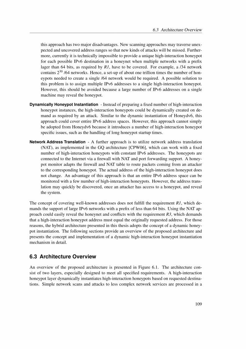
6.3 Architecture Overview
this approach has two major disadvantages. New scanning approaches may traverse unex-pected and uncovered address ranges so that new kinds of attacks will be missed. Further-more, currently it is technically impossible to provide a unique high-interaction honeypotfor each possible IPv6 destination in a honeynet when multiple networks with a prefixlager than 64 bits, as required by R1, have to be covered. For example, a /34 networkcontains 230 /64 networks. Hence, a set-up of about one trillion times the number of hon-eypots needed to create a single /64 network would be required. A possible solution tothis problem is to assign multiple IPv6 addresses to a single high-interaction honeypot.However, this should be avoided because a large number of IPv6 addresses on a singlemachine may reveal the honeypot.
Dynamically Honeypot Instantiation - Instead of preparing a fixed number of high-interactionhoneypot instances, the high-interaction honeypots could be dynamically created on de-mand as required by an attack. Similar to the dynamic instantiation of Honeydv6, thisapproach could cover entire IPv6 address spaces. However, this approach cannot simplybe adopted from Honeydv6 because it introduces a number of high-interaction honeypotspecific issues, such as the handling of long honeypot startup times.
Network Address Translation - A further approach is to utilize network address translation(NAT), as implemented in the GQ architecture [CPW06], which can work with a fixednumber of high-interaction honeypots with constant IPv6 addresses. The honeypots areconnected to the Internet via a firewall with NAT and port forwarding support. A honey-pot monitor adapts the firewall and NAT table to route packets coming from an attackerto the corresponding honeypot. The actual address of the high-interaction honeypot doesnot change. An advantage of this approach is that an entire IPv6 address space can bemonitored with a few number of high-interaction honeypots. However, the address trans-lation may quickly be discovered, once an attacker has access to a honeypot, and revealthe system.
The concept of covering well-known addresses does not fulfill the requirement R1, which de-mands the support of large IPv6 networks with a prefix of less than 64 bits. Using the NAT ap-proach could easily reveal the honeynet and conflicts with the requirement R3, which demandsthat a high-interaction honeypot address must equal the originally requested address. For thosereasons, the hybrid architecture presented in this thesis adopts the concept of a dynamic honey-pot instantiation. The following sections provide an overview of the proposed architecture andpresents the concept and implementation of a dynamic high-interaction honeypot instantiationmechanism in detail.
6.3 Architecture Overview
An overview of the proposed architecture is presented in Figure 6.1. The architecture con-sist of two layers, especially designed to meet all specified requirements. A high-interactionhoneypot layer dynamically instantiates high-interaction honeypots based on requested destina-tions. Simple network scans and attacks to less complex network services are processed in a
109
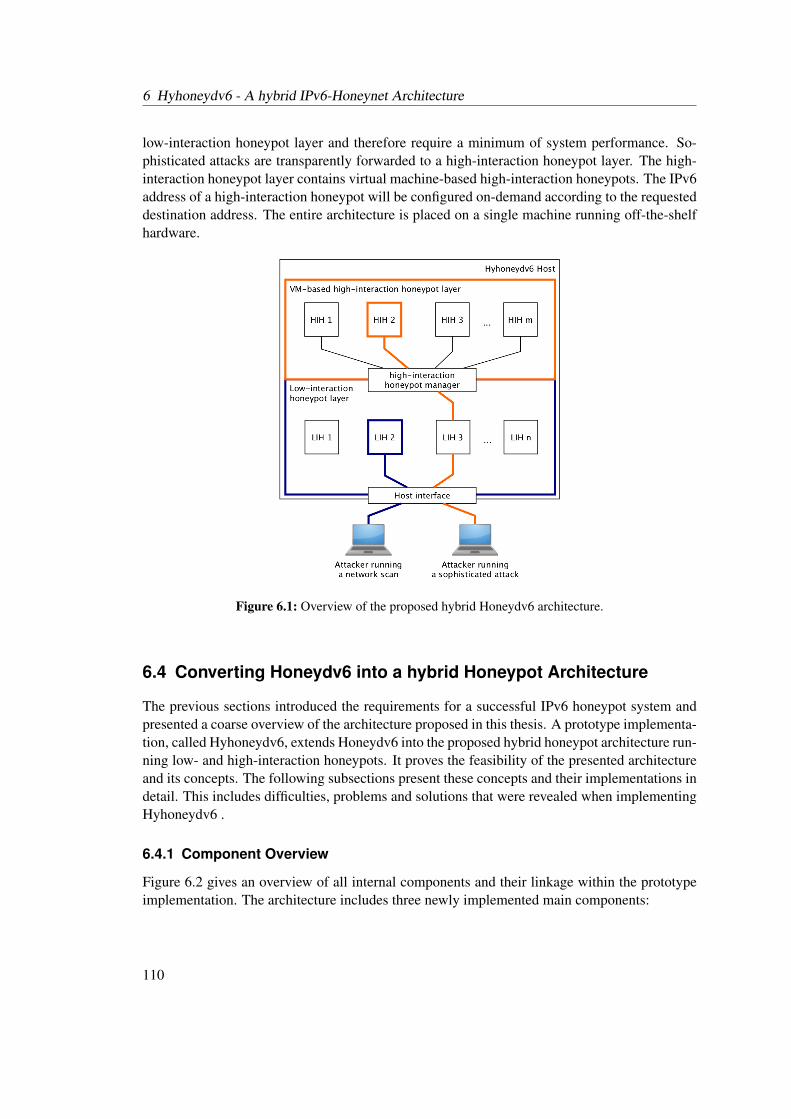
6 Hyhoneydv6 - A hybrid IPv6-Honeynet Architecture
low-interaction honeypot layer and therefore require a minimum of system performance. So-phisticated attacks are transparently forwarded to a high-interaction honeypot layer. The high-interaction honeypot layer contains virtual machine-based high-interaction honeypots. The IPv6address of a high-interaction honeypot will be configured on-demand according to the requesteddestination address. The entire architecture is placed on a single machine running off-the-shelfhardware.
Figure 6.1: Overview of the proposed hybrid Honeydv6 architecture.
6.4 Converting Honeydv6 into a hybrid Honeypot Architecture
The previous sections introduced the requirements for a successful IPv6 honeypot system andpresented a coarse overview of the architecture proposed in this thesis. A prototype implementa-tion, called Hyhoneydv6, extends Honeydv6 into the proposed hybrid honeypot architecture run-ning low- and high-interaction honeypots. It proves the feasibility of the presented architectureand its concepts. The following subsections present these concepts and their implementations indetail. This includes difficulties, problems and solutions that were revealed when implementingHyhoneydv6 .
6.4.1 Component Overview
Figure 6.2 gives an overview of all internal components and their linkage within the prototypeimplementation. The architecture includes three newly implemented main components:
110
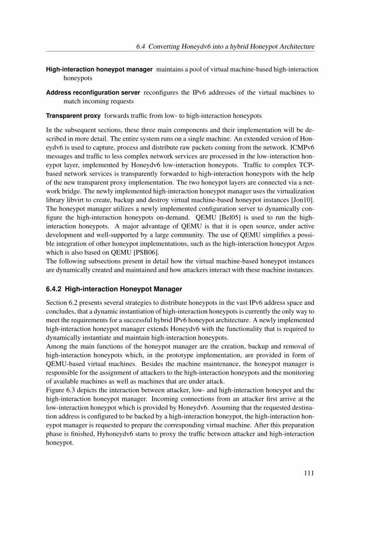
6.4 Converting Honeydv6 into a hybrid Honeypot Architecture
High-interaction honeypot manager maintains a pool of virtual machine-based high-interactionhoneypots
Address reconfiguration server reconfigures the IPv6 addresses of the virtual machines tomatch incoming requests
Transparent proxy forwards traffic from low- to high-interaction honeypots
In the subsequent sections, these three main components and their implementation will be de-scribed in more detail. The entire system runs on a single machine. An extended version of Hon-eydv6 is used to capture, process and distribute raw packets coming from the network. ICMPv6messages and traffic to less complex network services are processed in the low-interaction hon-eypot layer, implemented by Honeydv6 low-interaction honeypots. Traffic to complex TCP-based network services is transparently forwarded to high-interaction honeypots with the helpof the new transparent proxy implementation. The two honeypot layers are connected via a net-work bridge. The newly implemented high-interaction honeypot manager uses the virtualizationlibrary libvirt to create, backup and destroy virtual machine-based honeypot instances [Jon10].The honeypot manager utilizes a newly implemented configuration server to dynamically con-figure the high-interaction honeypots on-demand. QEMU [Bel05] is used to run the high-interaction honeypots. A major advantage of QEMU is that it is open source, under activedevelopment and well-supported by a large community. The use of QEMU simplifies a possi-ble integration of other honeypot implementations, such as the high-interaction honeypot Argoswhich is also based on QEMU [PSB06].The following subsections present in detail how the virtual machine-based honeypot instancesare dynamically created and maintained and how attackers interact with these machine instances.
6.4.2 High-interaction Honeypot Manager
Section 6.2 presents several strategies to distribute honeypots in the vast IPv6 address space andconcludes, that a dynamic instantiation of high-interaction honeypots is currently the only way tomeet the requirements for a successful hybrid IPv6 honeypot architecture. A newly implementedhigh-interaction honeypot manager extends Honeydv6 with the functionality that is required todynamically instantiate and maintain high-interaction honeypots.Among the main functions of the honeypot manager are the creation, backup and removal ofhigh-interaction honeypots which, in the prototype implementation, are provided in form ofQEMU-based virtual machines. Besides the machine maintenance, the honeypot manager isresponsible for the assignment of attackers to the high-interaction honeypots and the monitoringof available machines as well as machines that are under attack.Figure 6.3 depicts the interaction between attacker, low- and high-interaction honeypot and thehigh-interaction honeypot manager. Incoming connections from an attacker first arrive at thelow-interaction honeypot which is provided by Honeydv6. Assuming that the requested destina-tion address is configured to be backed by a high-interaction honeypot, the high-interaction hon-eypot manager is requested to prepare the corresponding virtual machine. After this preparationphase is finished, Hyhoneydv6 starts to proxy the traffic between attacker and high-interactionhoneypot.
111
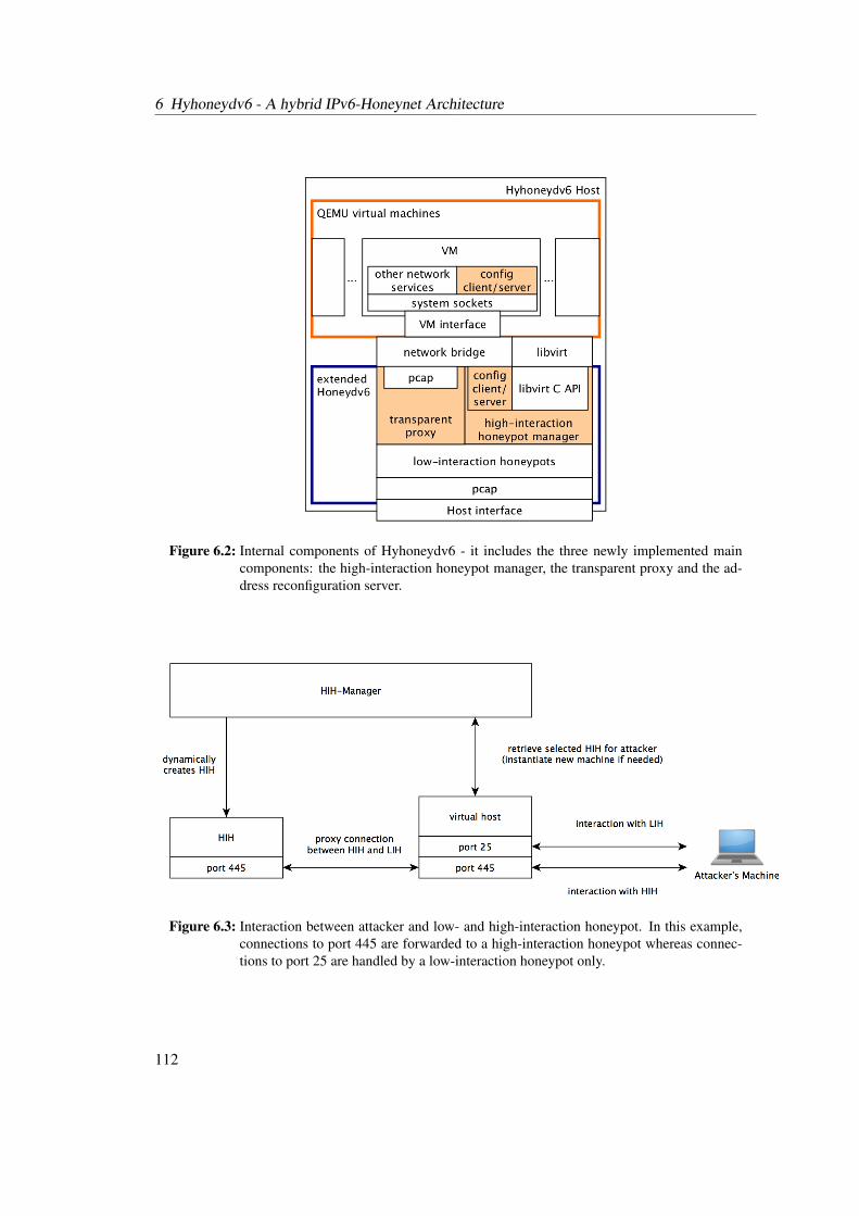
6 Hyhoneydv6 - A hybrid IPv6-Honeynet Architecture
Figure 6.2: Internal components of Hyhoneydv6 - it includes the three newly implemented maincomponents: the high-interaction honeypot manager, the transparent proxy and the ad-dress reconfiguration server.
Figure 6.3: Interaction between attacker and low- and high-interaction honeypot. In this example,connections to port 445 are forwarded to a high-interaction honeypot whereas connec-tions to port 25 are handled by a low-interaction honeypot only.
112
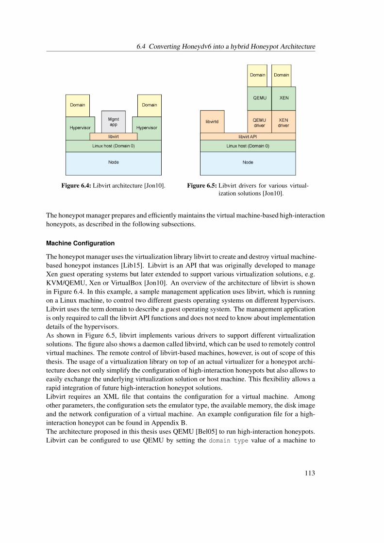
6.4 Converting Honeydv6 into a hybrid Honeypot Architecture
Figure 6.4: Libvirt architecture [Jon10]. Figure 6.5: Libvirt drivers for various virtual-ization solutions [Jon10].
The honeypot manager prepares and efficiently maintains the virtual machine-based high-interactionhoneypots, as described in the following subsections.
Machine Configuration
The honeypot manager uses the virtualization library libvirt to create and destroy virtual machine-based honeypot instances [Lib15]. Libvirt is an API that was originally developed to manageXen guest operating systems but later extended to support various virtualization solutions, e.g.KVM/QEMU, Xen or VirtualBox [Jon10]. An overview of the architecture of libvirt is shownin Figure 6.4. In this example, a sample management application uses libvirt, which is runningon a Linux machine, to control two different guests operating systems on different hypervisors.Libvirt uses the term domain to describe a guest operating system. The management applicationis only required to call the libvirt API functions and does not need to know about implementationdetails of the hypervisors.As shown in Figure 6.5, libvirt implements various drivers to support different virtualizationsolutions. The figure also shows a daemon called libvirtd, which can be used to remotely controlvirtual machines. The remote control of libvirt-based machines, however, is out of scope of thisthesis. The usage of a virtualization library on top of an actual virtualizer for a honeypot archi-tecture does not only simplify the configuration of high-interaction honeypots but also allows toeasily exchange the underlying virtualization solution or host machine. This flexibility allows arapid integration of future high-interaction honeypot solutions.Libvirt requires an XML file that contains the configuration for a virtual machine. Amongother parameters, the configuration sets the emulator type, the available memory, the disk imageand the network configuration of a virtual machine. An example configuration file for a high-interaction honeypot can be found in Appendix B.The architecture proposed in this thesis uses QEMU [Bel05] to run high-interaction honeypots.Libvirt can be configured to use QEMU by setting the domain type value of a machine to
113
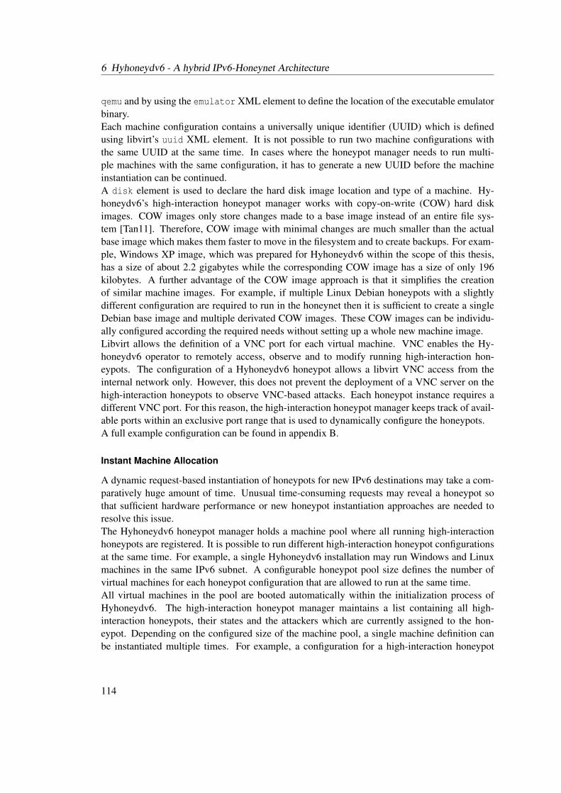
6 Hyhoneydv6 - A hybrid IPv6-Honeynet Architecture
qemu and by using the emulator XML element to define the location of the executable emulatorbinary.Each machine configuration contains a universally unique identifier (UUID) which is definedusing libvirt’s uuid XML element. It is not possible to run two machine configurations withthe same UUID at the same time. In cases where the honeypot manager needs to run multi-ple machines with the same configuration, it has to generate a new UUID before the machineinstantiation can be continued.A disk element is used to declare the hard disk image location and type of a machine. Hy-honeydv6’s high-interaction honeypot manager works with copy-on-write (COW) hard diskimages. COW images only store changes made to a base image instead of an entire file sys-tem [Tan11]. Therefore, COW image with minimal changes are much smaller than the actualbase image which makes them faster to move in the filesystem and to create backups. For exam-ple, Windows XP image, which was prepared for Hyhoneydv6 within the scope of this thesis,has a size of about 2.2 gigabytes while the corresponding COW image has a size of only 196kilobytes. A further advantage of the COW image approach is that it simplifies the creationof similar machine images. For example, if multiple Linux Debian honeypots with a slightlydifferent configuration are required to run in the honeynet then it is sufficient to create a singleDebian base image and multiple derivated COW images. These COW images can be individu-ally configured according the required needs without setting up a whole new machine image.Libvirt allows the definition of a VNC port for each virtual machine. VNC enables the Hy-honeydv6 operator to remotely access, observe and to modify running high-interaction hon-eypots. The configuration of a Hyhoneydv6 honeypot allows a libvirt VNC access from theinternal network only. However, this does not prevent the deployment of a VNC server on thehigh-interaction honeypots to observe VNC-based attacks. Each honeypot instance requires adifferent VNC port. For this reason, the high-interaction honeypot manager keeps track of avail-able ports within an exclusive port range that is used to dynamically configure the honeypots.A full example configuration can be found in appendix B.
Instant Machine Allocation
A dynamic request-based instantiation of honeypots for new IPv6 destinations may take a com-paratively huge amount of time. Unusual time-consuming requests may reveal a honeypot sothat sufficient hardware performance or new honeypot instantiation approaches are needed toresolve this issue.The Hyhoneydv6 honeypot manager holds a machine pool where all running high-interactionhoneypots are registered. It is possible to run different high-interaction honeypot configurationsat the same time. For example, a single Hyhoneydv6 installation may run Windows and Linuxmachines in the same IPv6 subnet. A configurable honeypot pool size defines the number ofvirtual machines for each honeypot configuration that are allowed to run at the same time.All virtual machines in the pool are booted automatically within the initialization process ofHyhoneydv6. The high-interaction honeypot manager maintains a list containing all high-interaction honeypots, their states and the attackers which are currently assigned to the hon-eypot. Depending on the configured size of the machine pool, a single machine definition canbe instantiated multiple times. For example, a configuration for a high-interaction honeypot
114
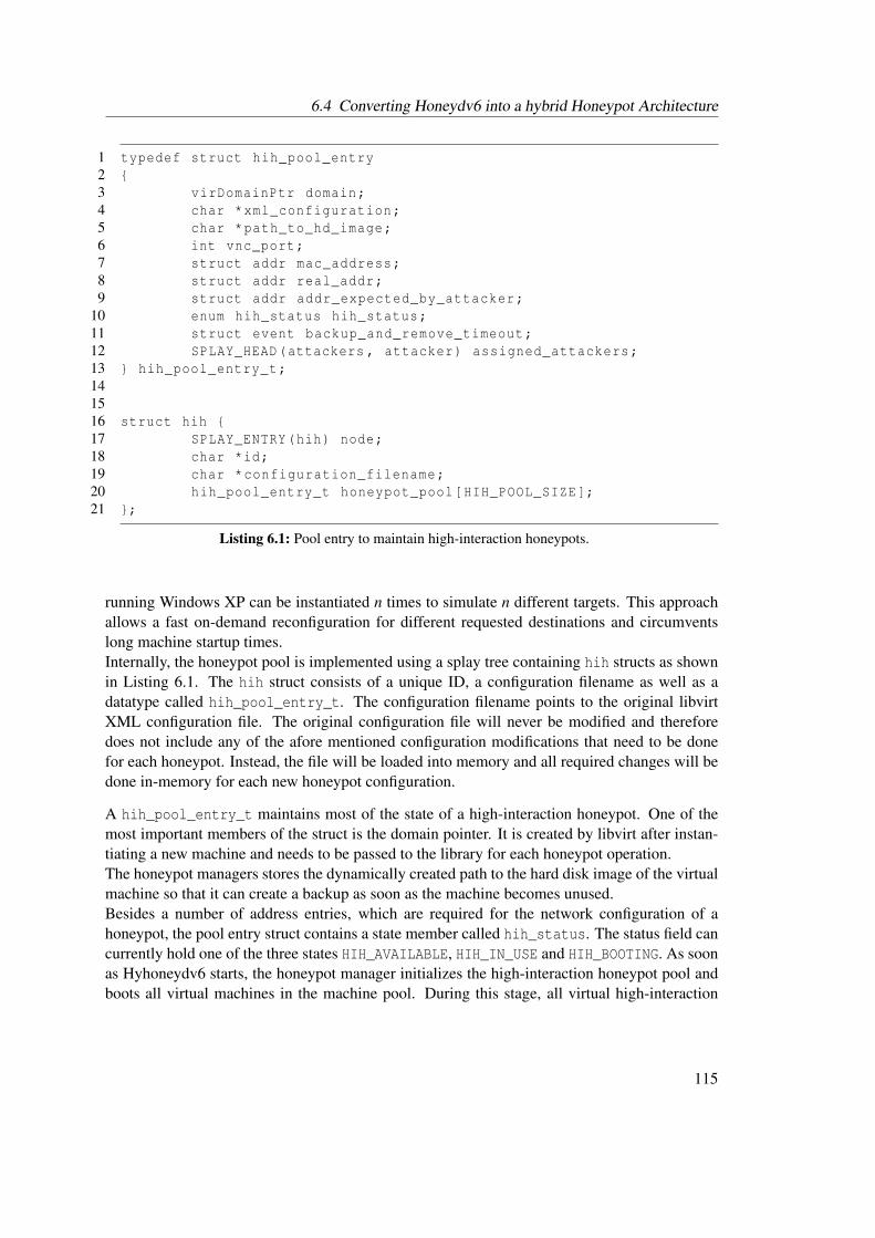
6.4 Converting Honeydv6 into a hybrid Honeypot Architecture
1 typedef struct hih_pool_entry2 {3 virDomainPtr domain;4 char *xml_configuration;5 char *path_to_hd_image;6 int vnc_port;7 struct addr mac_address;8 struct addr real_addr;9 struct addr addr_expected_by_attacker;
10 enum hih_status hih_status;11 struct event backup_and_remove_timeout;12 SPLAY_HEAD(attackers , attacker) assigned_attackers;13 } hih_pool_entry_t;141516 struct hih {17 SPLAY_ENTRY(hih) node;18 char *id;19 char *configuration_filename;20 hih_pool_entry_t honeypot_pool[HIH_POOL_SIZE];21 };
Listing 6.1: Pool entry to maintain high-interaction honeypots.
running Windows XP can be instantiated n times to simulate n different targets. This approachallows a fast on-demand reconfiguration for different requested destinations and circumventslong machine startup times.Internally, the honeypot pool is implemented using a splay tree containing hih structs as shownin Listing 6.1. The hih struct consists of a unique ID, a configuration filename as well as adatatype called hih_pool_entry_t. The configuration filename points to the original libvirtXML configuration file. The original configuration file will never be modified and thereforedoes not include any of the afore mentioned configuration modifications that need to be donefor each honeypot. Instead, the file will be loaded into memory and all required changes will bedone in-memory for each new honeypot configuration.
A hih_pool_entry_t maintains most of the state of a high-interaction honeypot. One of themost important members of the struct is the domain pointer. It is created by libvirt after instan-tiating a new machine and needs to be passed to the library for each honeypot operation.The honeypot managers stores the dynamically created path to the hard disk image of the virtualmachine so that it can create a backup as soon as the machine becomes unused.Besides a number of address entries, which are required for the network configuration of ahoneypot, the pool entry struct contains a state member called hih_status. The status field cancurrently hold one of the three states HIH_AVAILABLE, HIH_IN_USE and HIH_BOOTING. As soonas Hyhoneydv6 starts, the honeypot manager initializes the high-interaction honeypot pool andboots all virtual machines in the machine pool. During this stage, all virtual high-interaction
115
6 Hyhoneydv6 - A hybrid IPv6-Honeynet Architecture
honeypots are in the HIH_BOOTING state. When a honeypot finished the booting process, itnotifies the honeypot manager and changes into the state HIH_AVAILABLE. How the notificationprocess works is explained in detail in Section 6.4.3. The HIH_AVAILABLE state indicates thatthe honeypot has booted completely and that no attackers are assigned to the honeypot. Fornew incoming attacks, Hyhoneydv6 may request the honeypot manager to find an applicablehigh-interaction honeypot. The manager searches through its machine pool for honeypots thatare in the state HIH_AVAILABLE. After assigning an attacker to a high-interaction honeypot, thecorresponding machine state will be changed to HIH_IN_USE. A machine in this state is onlyavailable for further attackers who request the same destination.After a configurable timeout, a machine in the state HIH_IN_USE is considered unused andan automatic memory and hard disk backup will be created. The honeypot manager uses thebackup_and_remove_timeout event in the hih_pool_entry struct to store the needed backupinformation. As soon as the backup has finished, a new machine for the newly released pool slotwill be created and the booting process started.
Automatic backup
The honeypot manager automatically cleans up the machine pool by removing unused machinesafter a configurable timeout. A memory backup is copied into a separate backup folder on thehost that is running Hyhoneydv6. This is accomplished with the help of libvirt’s virDomainSavefunction which persists the memory state of a virtual machine in a file of a provided location.High-interaction honeypots never work directly on the configured base hard disk image. Hy-honeydv6 always creates a copy of the specified disk image. Therefore, there is no need tocreate another backup of the disk image. It is recommended to use COW hard disk images be-cause of their smaller size. This speeds up the Hyhoneydv6 booting process as shown later inthe performance measurement sections.
Network Configuration
The low- and the high-interaction honeypot layer is connected through a network bridge. Toavoid a direct access from the Internet to the high-interaction honeypots, the network interfaceof the host operating system is not directly connected to the bridge. Hyhoneydv6 provides aspecial TCP proxy mechanism, which is presented in Section 6.4.4, to transfer network trafficfrom the hosts network interface to the interfaces of the high-interaction honeypots.
116
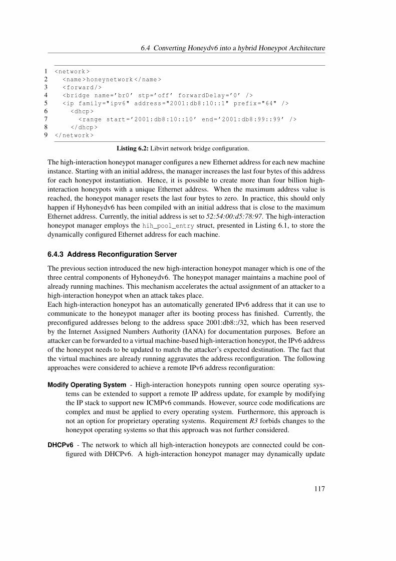
6.4 Converting Honeydv6 into a hybrid Honeypot Architecture
1 <network >2 <name >honeynetwork </name >3 <forward/>4 <bridge name=’br0’ stp=’off’ forwardDelay=’0’ />5 <ip family="ipv6" address ="2001:db8:10::1" prefix="64" />6 <dhcp >7 <range start=’2001:db8:10::10’ end=’2001:db8:99::99’ />8 </dhcp >9 </network >
Listing 6.2: Libvirt network bridge configuration.
The high-interaction honeypot manager configures a new Ethernet address for each new machineinstance. Starting with an initial address, the manager increases the last four bytes of this addressfor each honeypot instantiation. Hence, it is possible to create more than four billion high-interaction honeypots with a unique Ethernet address. When the maximum address value isreached, the honeypot manager resets the last four bytes to zero. In practice, this should onlyhappen if Hyhoneydv6 has been compiled with an initial address that is close to the maximumEthernet address. Currently, the initial address is set to 52:54:00:d5:78:97. The high-interactionhoneypot manager employs the hih_pool_entry struct, presented in Listing 6.1, to store thedynamically configured Ethernet address for each machine.
6.4.3 Address Reconfiguration Server
The previous section introduced the new high-interaction honeypot manager which is one of thethree central components of Hyhoneydv6. The honeypot manager maintains a machine pool ofalready running machines. This mechanism accelerates the actual assignment of an attacker to ahigh-interaction honeypot when an attack takes place.Each high-interaction honeypot has an automatically generated IPv6 address that it can use tocommunicate to the honeypot manager after its booting process has finished. Currently, thepreconfigured addresses belong to the address space 2001:db8::/32, which has been reservedby the Internet Assigned Numbers Authority (IANA) for documentation purposes. Before anattacker can be forwarded to a virtual machine-based high-interaction honeypot, the IPv6 addressof the honeypot needs to be updated to match the attacker’s expected destination. The fact thatthe virtual machines are already running aggravates the address reconfiguration. The followingapproaches were considered to achieve a remote IPv6 address reconfiguration:
Modify Operating System - High-interaction honeypots running open source operating sys-tems can be extended to support a remote IP address update, for example by modifyingthe IP stack to support new ICMPv6 commands. However, source code modifications arecomplex and must be applied to every operating system. Furthermore, this approach isnot an option for proprietary operating systems. Requirement R3 forbids changes to thehoneypot operating systems so that this approach was not further considered.
DHCPv6 - The network to which all high-interaction honeypots are connected could be con-figured with DHCPv6. A high-interaction honeypot manager may dynamically update
117
6 Hyhoneydv6 - A hybrid IPv6-Honeynet Architecture
the DHCPv6 configuration of the network and map the Ethernet addresses of the high-interaction honeypots to the corresponding IPv6 addresses. However, this approach re-quires the operating system running on the high-interaction honeypot to rerun its DHCPv6client to renew its IP configuration. For most operating systems, this process is done onstartup or when a link is reattached to the network. A reboot of the machine is not ap-plicable within the honeypot use case due to the time that is required to reboot a virtualmachine.
Remote Login - The architecture presented by Kishimoto et al. [KOY+12] uses SSH to re-configure the IPv6 address of a high-interaction honeypot before forwarding an attackerto the machine. This approach could be adopted in the Hyhoneydv6 architecture. Thehigh-interaction honeypot manager could reconfigure the operating system’s IP addressby using a remote shell service like SSH or telnet. However, Hyhoneydv6 needs to makesure that revealing shell history entries are either removed before allowing an attackeraccess to the system or not readable. Otherwise, an attacker could quickly detect the re-cent IP address update. This approach requires that all operating systems have a remotecommand-line login. In case of Windows machines, SSH does currently not belong to thedefault running services and an open SSH port may reveal the honeypot architecture.
Custom Server Instead of modifying the guest operating system or installing heavyweight net-work services, a custom server may be developed and installed on the high-interactionhoneypots. The server would have to wait for messages that contain IP address updates,apply the updates and remove all traces of itself before the attacker gets connected to thehigh-interaction honeypot. The server needs to be developed in a language and style thatis supported on all common operating systems. Otherwise, the maintenance work requiredto support different operating systems would increase to an unmaintainable level.
Due to the discussed restrictions of the DHCPv6 and the remote login approach, Hyhoneydv6applies a custom server to trigger the IPv6 address reconfiguration. The newly implementedIPv6 address configuration server is running on the high-interaction honeypots and is startedautomatically when the system has finished its booting process. The server sends a startupmessage to the honeypot manager which signalizes that the booting process has finished. Themessage contains a string of the semicolon separated Ethernet and IPv6 address of the virtualmachine. The honeypot manager maintains the preconfigured addresses and the address that isrequested by the attacker in the mac_address, real_addr and addr_expected_by_attackermembers of the hih_pool_entry structure that is shown in Listing 6.1.When Hyhoneydv6 requires a new high-interaction honeypot with a specific IPv6 address, thenthe honeypot manager starts the IPv6 address reconfiguration progress. The first step in thereconfiguration chain is the search for an available high-interaction honeypot. Hyhoneydv6’sconfiguration file defines the machine type that has be used for the dynamic instantiation pro-cess. If there is no honeypot for the selected machine type available, then the connection to theattacker will be closed. Otherwise, the honeypot manager sets the located machine into the stateHIH_IN_USE so that it becomes unavailable for further address reconfigurations. Hyhoneydv6’shoneypot manager uses the hih_pool_entry of the selected machine to obtain the preconfig-ured IPv6 address. This address is used to connect to server on the high-interaction honeypot to
118
6.4 Converting Honeydv6 into a hybrid Honeypot Architecture
start the IPv6 address reconfiguration process. Similar to the initial startup message, the IPv6address reconfiguration message includes a plain textual representation of the new IPv6 address.Because the startup and the reconfiguration messages are only send through the local network,there is no need for further protection or encryption.Besides the reconfiguration of IPv6 addresses and the communication to the honeypot manager,the IPv6 configuration server provides an initial address generation function for systems with-out DHCPv6 support, such as Windows XP [Mic15a]. The internal honeypot network doesnot include a SLAAC-enabled router. Therefore, without the newly implemented configurationserver or DHCPv6, these systems could not obtain a valid IPv6 address. Similar to SLAAC,the address configuration server generates and assign new valid IPv6 addresses based on themachines’ Ethernet addresses and the prefix of the honeypot network using the modified IPv6Extended Unique Identifier (EUI)-64 algorithm.
6.4.4 Transparent Proxy
Hyhoneydv6 uses low-interaction honeypots to process network scans and attacks to less com-plex network services. Attacks to complex network services are processed by high-interactionhoneypots. The hybrid approach provides great flexibility and reduces the load on the high-interaction honeypot layer. High-interaction honeypots are only assigned to an attacker if thecorresponding TCP handshake has been completed successfully. Hence, a simple TCP SYNscan is processed in the low-interaction honeypot layer only and does not unnecessarily allocatehigh-interaction honeypot instances. That implies, however, that Hyhoneydv6 must be able topass a connection that has already finished the initial TCP handshake from a low- to a high-interaction honeypot. The mechanism of reassigning an existing TCP connection to anothernode in the network is sometimes referred to as connection handoff [BCW+04].Requirement R3 prevents a modification of the high-interaction honeypot operating systemwhich impedes the development of a completely transparent handoff mechanism. The mainreason for this lies in the design of TCP, more precisely, in the way the initial three-way TCPhandshake works. In order to establish a connection to a server, a client needs to send a TCPpacket with an active SYN control flag to the server. Besides the active SYN flag, the packetcontains a random initial sequence number. If the server accepts the TCP connection, it respondswith a packet with an active SYN and ACK control flag. The server acknowledges the initialSYN packet from the client by sending an acknowledgement number that equals the client’sincremented initial sequence number. This second packet of the three-way TCP handshake alsocontains the server’s random initial sequence number. All future packet acknowledgements thatare sent from client to server are based on this server-side generated sequence number. It shouldnot be possible to predict the initial sequence number. Otherwise, an adversary could simpleintercept an established TCP connection. If the initial sequence number of a high-interactionhoneypot could be predicted, then Hyhoneydv6 could use this number to perform the TCP hand-shake on the low-interaction honeypots. As soon as a low-interaction honeypot is ready to handover a connection to a high-interaction honeypot, it could simply replay the TCP handshakewith the same sequence numbers that it used for the adversary and forward all subsequent pack-ets without any modification. However, as pointed out earlier, a sequence number prediction isnot possible and a different handoff approach is required.
119

6 Hyhoneydv6 - A hybrid IPv6-Honeynet Architecture
For a limited number of operating systems, there are modular designs and implementationsavailable which simplify a TCP connection handoff. One example is the TCP handoff designthat has been published by Tang et al. [TCRM01]. These solutions, however, are out of scopeof this document. They still require adjustments of the high-interaction honeypot operatingsystem or additional system software. The number of additional uncommon software on thehigh-interaction honeypots should be kept as low as possible to reduce the risk of revealing thehoneypot.This thesis proposes the following two approaches for implementing a honeypot specific TCPhandoff-like mechanism without the need for operating system modifications:
Proxied handoff - In case of a proxied handoff, the entire communication between attacker andhigh-interaction honeypot traverses the low-interaction honeypot as shown in Figure 6.6.The low-interaction honeypot first completes the TCP handshake with the attacker andthen opens a new connection to the high-interaction honeypot. Messages coming from theattacker are then forwarded to the high-interaction honeypot. In the same way, the high-interaction honeypot responses are tunneled back to the attacker. Because a connection tothe high-interaction honeypot is only established if the TCP handshake with the attackercould be successfully completed, TCP-SYN-scans do not require a high-interaction hon-eypot instance. Furthermore, this approach has the advantage that the entire communi-cation is flowing through the low-interaction honeypot layer. Hence, mechanisms suchas logging, shellcode detection or statistical analyses continue to work. This approach isstill limited to the capabilities provided by TCP. An implementation of an entirely trans-parent mechanism is not possible without operating system modifications. However, allmajor connection parameters, such as source address, destination address and ports, canbe included in the proxy process to conceal the honeypot.
Controlled bypass - The controlled bypass is depicted in Figure 6.7. Instead of acting as aproxy through the entire communication, the low-interaction honeypot only forwards thefirst TCP-SYN packet of the attacker to the high-interaction honeypot to establish a con-nection. When accepting a new connection, either a firewall rule update or a dynamicIPv6 address assignment enables the communication between honeypot and adversary.The advantage of this approach is that the actual TCP handshake is performed on the high-interaction honeypot only and no actual TCP handoff of an existing connection needs tobe done. Due to the fact that the low-interaction honeypot still needs to allow the firstpackage to be forwarded to the high-interaction honeypot, the low-interaction honeypotkeeps control over the number of connections being established. However, this approachrequires special mechanisms to deal with SYN flooding attacks and to avoid the unnec-essary allocation of high-interaction honeypots. When a connection request for a config-ured virtual target first arrives at the low-interaction honeypot, it is not clear whether thispacket belongs to TCP SYN scan. Each established connection to a different destinationaddress requires a new high-interaction honeypot instance. Therefore, a TCP SYN scanmay quickly exhaust the capabilities of the honeypot system.
Both approaches require an infrastructure which forbids an adversary to communicate directlyto a high-interaction honeypot without connecting to a low-interaction honeypot. Otherwise, an
120
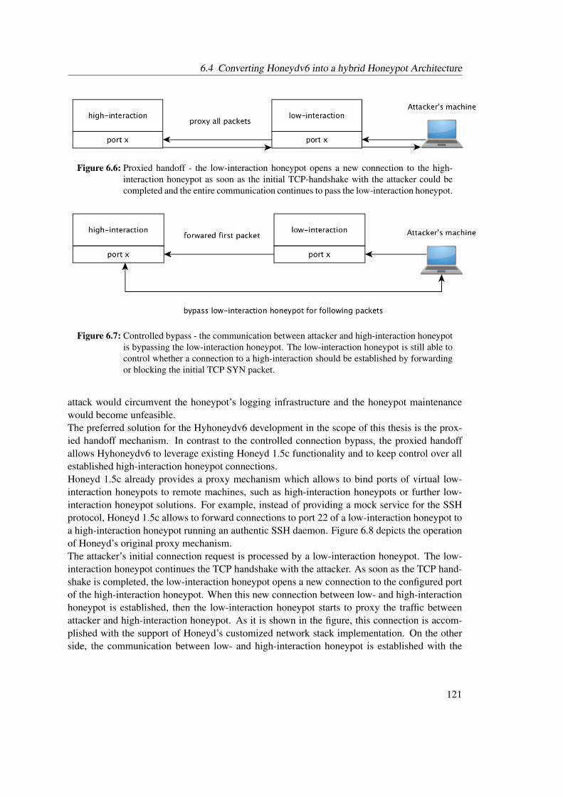
6.4 Converting Honeydv6 into a hybrid Honeypot Architecture
Figure 6.6: Proxied handoff - the low-interaction honeypot opens a new connection to the high-interaction honeypot as soon as the initial TCP-handshake with the attacker could becompleted and the entire communication continues to pass the low-interaction honeypot.
Figure 6.7: Controlled bypass - the communication between attacker and high-interaction honeypotis bypassing the low-interaction honeypot. The low-interaction honeypot is still able tocontrol whether a connection to a high-interaction should be established by forwardingor blocking the initial TCP SYN packet.
attack would circumvent the honeypot’s logging infrastructure and the honeypot maintenancewould become unfeasible.The preferred solution for the Hyhoneydv6 development in the scope of this thesis is the prox-ied handoff mechanism. In contrast to the controlled connection bypass, the proxied handoffallows Hyhoneydv6 to leverage existing Honeyd 1.5c functionality and to keep control over allestablished high-interaction honeypot connections.Honeyd 1.5c already provides a proxy mechanism which allows to bind ports of virtual low-interaction honeypots to remote machines, such as high-interaction honeypots or further low-interaction honeypot solutions. For example, instead of providing a mock service for the SSHprotocol, Honeyd 1.5c allows to forward connections to port 22 of a low-interaction honeypot toa high-interaction honeypot running an authentic SSH daemon. Figure 6.8 depicts the operationof Honeyd’s original proxy mechanism.The attacker’s initial connection request is processed by a low-interaction honeypot. The low-interaction honeypot continues the TCP handshake with the attacker. As soon as the TCP hand-shake is completed, the low-interaction honeypot opens a new connection to the configured portof the high-interaction honeypot. When this new connection between low- and high-interactionhoneypot is established, then the low-interaction honeypot starts to proxy the traffic betweenattacker and high-interaction honeypot. As it is shown in the figure, this connection is accom-plished with the support of Honeyd’s customized network stack implementation. On the otherside, the communication between low- and high-interaction honeypot is established with the
121
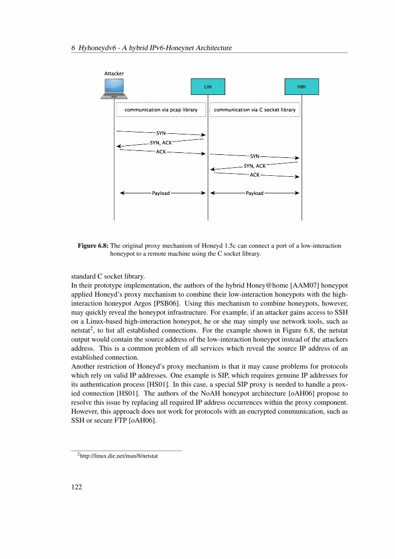
6 Hyhoneydv6 - A hybrid IPv6-Honeynet Architecture
Figure 6.8: The original proxy mechanism of Honeyd 1.5c can connect a port of a low-interactionhoneypot to a remote machine using the C socket library.
standard C socket library.In their prototype implementation, the authors of the hybrid Honey@home [AAM07] honeypotapplied Honeyd’s proxy mechanism to combine their low-interaction honeypots with the high-interaction honeypot Argos [PSB06]. Using this mechanism to combine honeypots, however,may quickly reveal the honeypot infrastructure. For example, if an attacker gains access to SSHon a Linux-based high-interaction honeypot, he or she may simply use network tools, such asnetstat2, to list all established connections. For the example shown in Figure 6.8, the netstatoutput would contain the source address of the low-interaction honeypot instead of the attackersaddress. This is a common problem of all services which reveal the source IP address of anestablished connection.Another restriction of Honeyd’s proxy mechanism is that it may cause problems for protocolswhich rely on valid IP addresses. One example is SIP, which requires genuine IP addresses forits authentication process [HS01]. In this case, a special SIP proxy is needed to handle a prox-ied connection [HS01]. The authors of the NoAH honeypot architecture [oAH06] propose toresolve this issue by replacing all required IP address occurrences within the proxy component.However, this approach does not work for protocols with an encrypted communication, such asSSH or secure FTP [oAH06].
2http://linux.die.net/man/8/netstat
122

6.4 Converting Honeydv6 into a hybrid Honeypot Architecture
Implementation of TCP Handoff and Payload Exchange into Honeydv6
The previous section introduced the idea behind Hyhoneydv6’s proxied handoff approach tohandover connections from low- to high-interaction honeypots. This section focuses on theimplementation and the Honeydv6 modifications that were required to integrate the TCP handoffmechanism into Honeydv6.The proxy implementation extends the customized IPv6 network stack of Honeydv6, whichprovides a high degree of control and transparency. All main IPv6 header fields, such as sourceand destination addresses, source and destination ports as well as the hop limit field, are adaptedwhen proxying traffic to a high-interaction honeypot. The resulting implementation does notrequire any changes to the implementation of the high-interaction honeypot operating system.Honeydv6’s configuration settings were extended so that users can enable the transparent proxymechanism using the proxy transparent keyword. For example, a user can use the followingstatement to specify a binding of port 22 of the low-interaction honeypot myhoneypot to a high-interaction honeypot having the name debian:
add myhoneypot tcp port 22 proxy transparent debian
The binding of a high-interaction honeypot is not limited to a single machine. It is even possibleto bind different high-interaction honeypots to different ports of the same low-interaction hon-eypot. However, it is recommend to bind the all ports of a low-interaction honeypot to the samehigh-interaction honeypot in order to avoid a disclosure of the honeypot infrastructure. Moredetails about the installation and configuration of high-interaction honeypots can be found inAppendix A.By configuring Hyhoneydv6 using the previous example configuration line, the payload of allestablished connections to port 22 of the low-interaction honeypot myhoneypot is forwardedto the high-interaction honeypot debian. TCP connections which do not properly completeinitial the three-way handshake are not forwarded to a high-interaction honeypot. This mech-anism reduces the system load when processing common TCP SYN scans where an adversaryfinishes the three-way handshake with an active RST flag which causes the system to drop theconnection.An example connection is depicted in Figure 6.9. In this example, an attacker first conductsa simple TCP SYN scan and finishes the three-way TCP handshake with an RST packet. Ina second attempt, the attacker actually establishes a connection to a low-interaction honeypotwith the IPv6 address 2001:db8::5. Hyhoneydv6 starts the IPv6 address reconfiguration of anavailable high-interaction honeypot as explained in Section 6.4.3. During the reconfigurationphase, the connection between low-interaction honeypot and the adversary is held open.The customized TCP stack of Honeydv6 was extended to be able to actively open connections.When opening a connection to a high-interaction honeypot, Hyhoneydv6 takes over severalproperties of the low-interaction honeypot connection. This includes the source and destina-tion address, source and destination port as well as the hop limit. Due to the restrictions of TCP,the sequence numbers can not be adopted from the low-interaction honeypot connection. There-fore, an attacker could still reveal the proxy implementation by using network packet inspectiontools to extract and compare the connection’s sequence numbers. However, common network
123
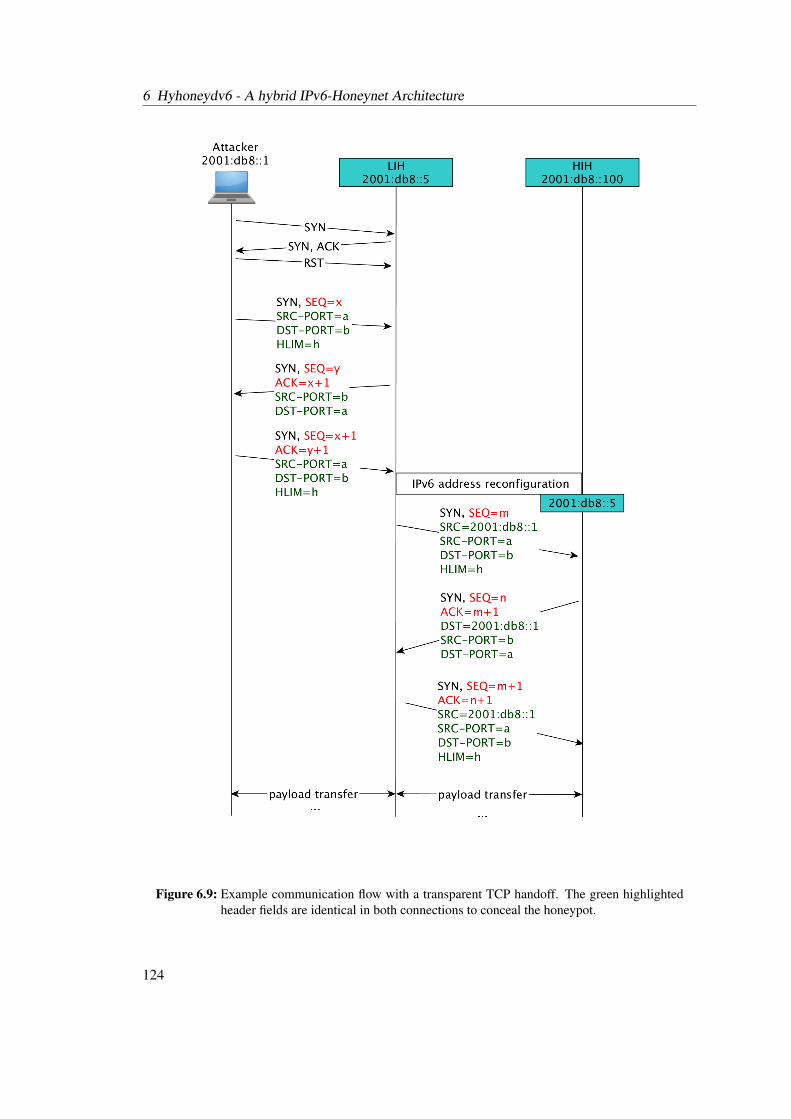
6 Hyhoneydv6 - A hybrid IPv6-Honeynet Architecture
Figure 6.9: Example communication flow with a transparent TCP handoff. The green highlightedheader fields are identical in both connections to conceal the honeypot.
124
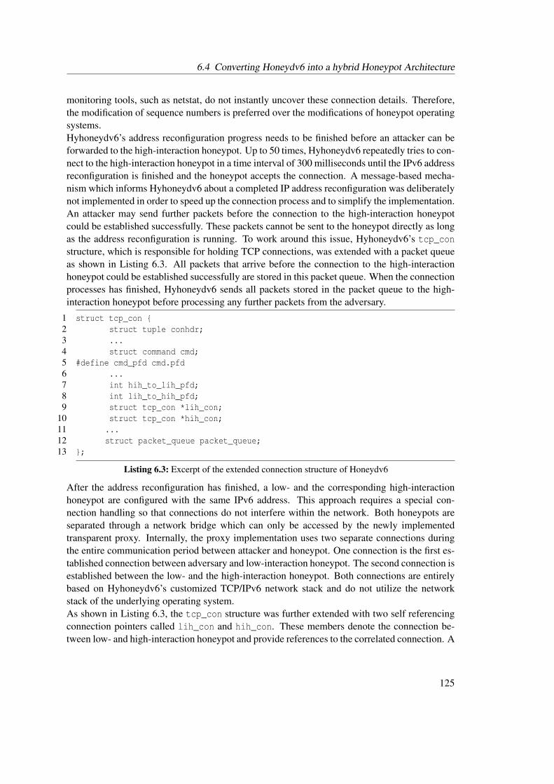
6.4 Converting Honeydv6 into a hybrid Honeypot Architecture
monitoring tools, such as netstat, do not instantly uncover these connection details. Therefore,the modification of sequence numbers is preferred over the modifications of honeypot operatingsystems.Hyhoneydv6’s address reconfiguration progress needs to be finished before an attacker can beforwarded to the high-interaction honeypot. Up to 50 times, Hyhoneydv6 repeatedly tries to con-nect to the high-interaction honeypot in a time interval of 300 milliseconds until the IPv6 addressreconfiguration is finished and the honeypot accepts the connection. A message-based mecha-nism which informs Hyhoneydv6 about a completed IP address reconfiguration was deliberatelynot implemented in order to speed up the connection process and to simplify the implementation.An attacker may send further packets before the connection to the high-interaction honeypotcould be established successfully. These packets cannot be sent to the honeypot directly as longas the address reconfiguration is running. To work around this issue, Hyhoneydv6’s tcp_constructure, which is responsible for holding TCP connections, was extended with a packet queueas shown in Listing 6.3. All packets that arrive before the connection to the high-interactionhoneypot could be established successfully are stored in this packet queue. When the connectionprocesses has finished, Hyhoneydv6 sends all packets stored in the packet queue to the high-interaction honeypot before processing any further packets from the adversary.
1 struct tcp_con {2 struct tuple conhdr;3 ...4 struct command cmd;5 #define cmd_pfd cmd.pfd6 ...7 int hih_to_lih_pfd;8 int lih_to_hih_pfd;9 struct tcp_con *lih_con;
10 struct tcp_con *hih_con;11 ...12 struct packet_queue packet_queue;13 };
Listing 6.3: Excerpt of the extended connection structure of Honeydv6
After the address reconfiguration has finished, a low- and the corresponding high-interactionhoneypot are configured with the same IPv6 address. This approach requires a special con-nection handling so that connections do not interfere within the network. Both honeypots areseparated through a network bridge which can only be accessed by the newly implementedtransparent proxy. Internally, the proxy implementation uses two separate connections duringthe entire communication period between attacker and honeypot. One connection is the first es-tablished connection between adversary and low-interaction honeypot. The second connection isestablished between the low- and the high-interaction honeypot. Both connections are entirelybased on Hyhoneydv6’s customized TCP/IPv6 network stack and do not utilize the networkstack of the underlying operating system.As shown in Listing 6.3, the tcp_con structure was further extended with two self referencingconnection pointers called lih_con and hih_con. These members denote the connection be-tween low- and high-interaction honeypot and provide references to the correlated connection. A
125

6 Hyhoneydv6 - A hybrid IPv6-Honeynet Architecture
non-NULL lih_con pointer indicates that the current connection structure is a high-interactionhoneypot while a non-NULL hih_con pointer indicates that the connection is a low-interactionhoneypot. A tcp_con cannot stand for a low- and a high-interaction honeypot at the same time.Thus, at most one of both connection pointers can be set to a non-NULL value. Whenever Hy-honeydv6 needs to identify the type of a connection or when it requires access to an attached low-or high-interaction honeypot connection, it employs these members of the connection structure.Besides the previously introduced connection pointers, two file descriptor members were addedto the TCP connection structure. These file descriptors are used for the actual TCP payloadexchange between both connections. Similar to the connection pointers, only one of both filedescriptors must be initialized, depending on the type of the connection.To some extend, the data exchange implementation between low- and high honeypots reusescomponents provided by Honeyd 1.5c. The understanding of the proposed concept requires aninsight into how the original Honeyd version exchanges data between service scripts and low-interaction honeypots. Honeyd 1.5c uses the system call execvp to execute service scripts whichimplement the actual network service functionality. By executing the system calls socketpairand dup2, Honeyd creates two pairs of sockets to connect the standard output and the standarderror of a service script to the corresponding low-interaction honeypot connection.After establishing the connection to the service script, the low-interaction honeypot can use afile descriptor called pfd for the exchange of data. The file descriptor pfd is a member of thecommand structure that is stored in the tcp_con structure and can be referenced by cmd_pfd, asshown in Listing 6.3. Hyhoneydv6 extends this mechanism to allow the communication betweenlow- and high-interaction honeypots.
Figure 6.10: Multiple internal file descriptors allow a data exchange between low- and high-interaction honeypot connections.
Figure 6.10 gives a coarse overview of the traffic flow between attacker and high-interactionhoneypot. Traffic coming from the attacker flows through the custom network stack and isprocessed by a low-interaction honeypot connection.Hyhoneydv6 uses the file descriptor lih_to_hih_pfd on the low-interaction honeypot side toforward the traffic to the file descriptor pfd of the corresponding high-interaction honeypot.Similar to the process of reading service script outputs, the high-interaction honeypot reads thisinput from the pfd file descriptor and forwards it through the customized network stack to the
126
6.5 Summary
assigned virtual machine. Responses coming from the virtual machine are directly written intothe hih_to_lih_pfd file descriptor. Similar to the high-interaction honeypot connection, thelow-interaction honeypot reads this response from its pfd file descriptor and forwards the outputvia the customized network stack to the attacker’s machine.At a first glance, the usage of two separate file descriptors may seem unnecessarily complex.However, this way the integration of the transparent proxy was less complicated. Employingonly a single file descriptor on each honeypot side would require multiple changes to Honeyd’slibevent based packet processing.
6.4.5 Attack Distribution
In [CPW06], the authors create a new honeypot instance for every attack with a distinct sourceIP address. This approach allows observing attacks from different adversaries in an isolatedmanner. A stored machine state can be correlated to a single adversary. To analyze a specificattack, this approach does not require to extract the corresponding commands from an unclearcommand set belonging to different attacks. Because of the limited number of available IPv4addresses, the approach works well in IPv4 networks. In case of attacks that are performed inIPv6 networks, it is more probable that an attacker uses different IPv6 source addresses than inIPv4 networks. This mainly has the following reasons:
• The IPv6 address space is much larger than the IPv4 address space. For Internet ServiceProviders (ISPs), it is very common to hand out entire IPv6 address spaces even to theirprivate customers instead of single addresses as it is the case for IPv4 addresses. Hence,an attacker has a lot more addresses to choose from. The darknet results, presented inChapter 5, have shown that address spaces are scanned from different source addresseswhich actually belong to the same institution. Classical defense mechanism which blockconspicuous IP addresses will therefore not work in IPv6 networks. This fact may furtherinduce attackers to constantly change their IPv6 source addresses.
• An attacker may have IPv6 privacy extensions enabled [NDK07]. Thus, the attacker’soperating system may use different IPv6 source addresses for different connections au-tomatically. Further information about IPv6 privacy extensions can be found in section2.1.6.
For these reasons, Hyhoneydv6 assigns incoming network traffic to high-interaction honeypotsbased on the target addresses without considering the attackers’ source addresses. Analyses ofthe darknet results, shown in Chapter 5, confirm that the chance of being contacted from twodifferent source addresses belonging to the same institution is much higher than two independentadversaries attacking the same machine.
6.5 Summary
A major drawback of the earlier presented low-interaction honeypot framework Honeydv6 isits limitation to service scripts. In contrast to high-interaction honeypots, which deploy real
127
6 Hyhoneydv6 - A hybrid IPv6-Honeynet Architecture
network services, service scripts only provide an emulated version of a service up to a certaingranularity. Complex or proprietary network services may be difficult or even impossible toimplement. High-interaction honeypots, on the other hand, can hardly be deployed throughentire IPv6 networks due to their larger performance requirements. This section presented thehybrid honeypot architecture Hyhoneydv6. By combining low- and high-interaction honeypots,Hyhoneydv6 can provide the same flexibility as Honeydv6 while providing genuine networkservices. Network scans and attacks to less sophisticated network services are processed bylow-interaction honeypots. Attacks to complex or even proprietary network services are handledby high-interaction honeypots.This section discussed three different honeypot distribution strategies and comes to the con-clusion, that a dynamic instantiation of high-interaction honeypots is the preferable strategyfor the honeypot deployment in IPv6 networks. Three newly implemented Hyhoneydv6 corecomponents make the dynamic instantiation of high-interaction honeypots possible: a high-interaction honeypot manager, an address reconfiguration server and a transparent proxy. Thehigh-interaction honeypot manager maintains a pool of virtual machine-based high-interactionhoneypots. It is responsible for the creation and backup of the virtual machines as well as the as-signment of attackers. The address reconfiguration server is one of four evaluated mechanisms todynamically update the IPv6 address on the virtual machines on-demand, based on the requestedtargets. Before assigning an attacker to a high-interaction honeypot, the honeypot manager trig-gers the address reconfiguration so that the IPv6 address of a high-interaction honeypot equalsthe address that is expected by an attacker. The transparent proxy implementation allows to for-ward attackers from low- to high-interaction honeypots. It adopts all main IPv6 header fields ofa low-interaction honeypot connection so that the migration appears transparent to the attacker.Hyhoneydv6 assigns the same IPv6 address to connected low- and high-interaction honeypots.Both honeypot types are separated by a network bridge. By evaluating the utilized interfaces,the transparent proxy implementation is able to distinguish between connections to low- andhigh-interaction honeypots even though their header fields are equal.Hyhoneydv6 is not limited to a specific hypervisor and allows the integration of various high-interaction honeypot solutions, such as the Argos honeypot project [PSB06]. The performancemeasurements, presented in the following chapter, show that Hyhoneydv6 performs well onoff-the-shelf hardware.
128
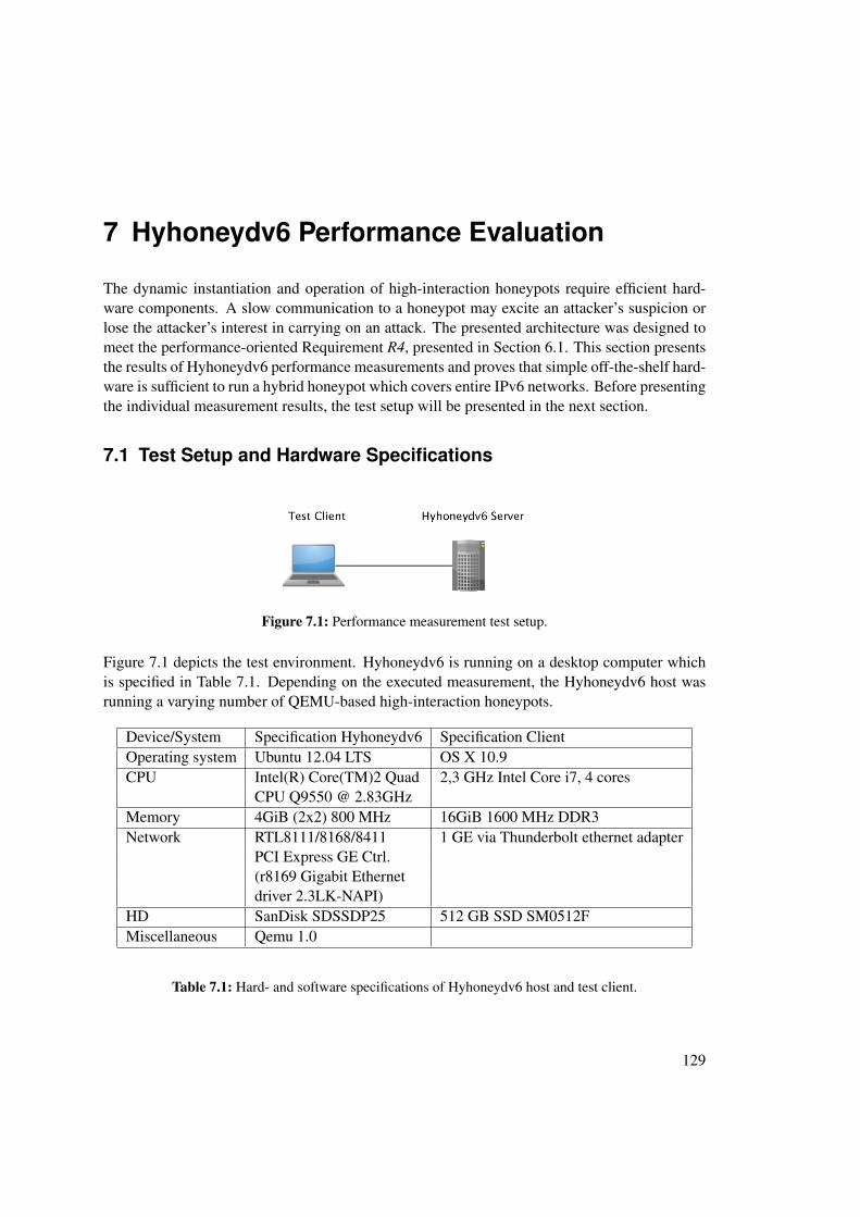
7 Hyhoneydv6 Performance Evaluation
The dynamic instantiation and operation of high-interaction honeypots require efficient hard-ware components. A slow communication to a honeypot may excite an attacker’s suspicion orlose the attacker’s interest in carrying on an attack. The presented architecture was designed tomeet the performance-oriented Requirement R4, presented in Section 6.1. This section presentsthe results of Hyhoneydv6 performance measurements and proves that simple off-the-shelf hard-ware is sufficient to run a hybrid honeypot which covers entire IPv6 networks. Before presentingthe individual measurement results, the test setup will be presented in the next section.
7.1 Test Setup and Hardware Specifications
Figure 7.1: Performance measurement test setup.
Figure 7.1 depicts the test environment. Hyhoneydv6 is running on a desktop computer whichis specified in Table 7.1. Depending on the executed measurement, the Hyhoneydv6 host wasrunning a varying number of QEMU-based high-interaction honeypots.
Device/System Specification Hyhoneydv6 Specification ClientOperating system Ubuntu 12.04 LTS OS X 10.9CPU Intel(R) Core(TM)2 Quad 2,3 GHz Intel Core i7, 4 cores
CPU Q9550 @ 2.83GHzMemory 4GiB (2x2) 800 MHz 16GiB 1600 MHz DDR3Network RTL8111/8168/8411 1 GE via Thunderbolt ethernet adapter
PCI Express GE Ctrl.(r8169 Gigabit Ethernetdriver 2.3LK-NAPI)
HD SanDisk SDSSDP25 512 GB SSD SM0512FMiscellaneous Qemu 1.0
Table 7.1: Hard- and software specifications of Hyhoneydv6 host and test client.
129

7 Hyhoneydv6 Performance Evaluation
0.001
0.01
0.1
1
10
100
1000
1 10 100 1000 10000
cop
y t
ime in s
eco
nd
s
image size in MB
image copy duration
Figure 7.2: Average copy time comparisons.
A client machine, which is also specified in Table 7.1, was directly connected to the Hyhoneydv6host and utilized whenever client interaction was required.
7.2 Machine Creation, Boot and Backup Time
The first number of measurements focused on the time that Hyhoneydv6 requires to start andinitialize its machine pool. Hyhoneydv6 creates a copy of the hard disk image for each newvirtual high-interaction honeypot before it starts the boot process. The size of this hard diskimage may have a significant influence on the total honeypot startup time. The first measurementwas conducted to find out how the boot time increases for larger machine image sizes.Hyhoneydv6’s image copy process does not verify the validity of a machine image. This factallowed to measure the boot time using five non-functional random machine images with specificsizes. By using the Linux command line utility dd together with the pseudorandom generator/dev/urandom, a 1MB, 10MB, 100MB, 1GB and a 10GB image file was created. Furthermore,measuring points were integrated around Hyhoneydv6’s image copy mechanism to determinethe exact time needed to create an image copy. The copy process was repeated five times foreach image size. Figure 7.2 shows the median results of this measurements.As shown in Figure 7.2, the copy time increases almost linear with a growing image size. Ittakes less then 10 milliseconds to copy a 1MB image file and still less than a second to copya 100MB image file, which is a realistic size for common initial COW disk images. A 10GBdisk image, however, requires about two minutes until the copy process finishes. It is thereforerecommended to only use COW disk images when running Hyhoneydv6 because a full-size diskimage copy would unnecessarily slow down the high-interaction honeypot startup process.When the copy process could be finished successfully, Hyhoneydv6 begins to startup the high-interaction honeypots. A second measurement determined the exact startup time of machines
130
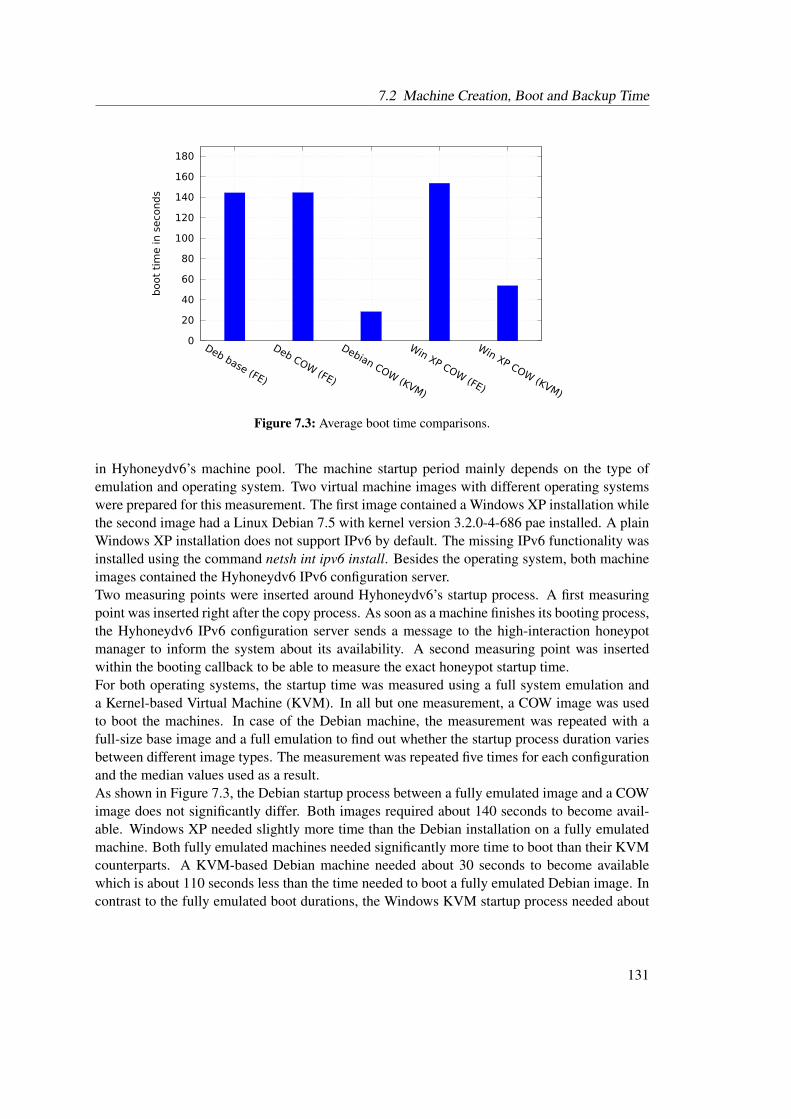
7.2 Machine Creation, Boot and Backup Time
0
20
40
60
80
100
120
140
160
180
Deb base (FE)
Deb COW (FE)
Debian COW (KVM)
Win XP COW (FE)
Win XP COW (KVM)
boot
tim
e in s
eco
nd
s
Figure 7.3: Average boot time comparisons.
in Hyhoneydv6’s machine pool. The machine startup period mainly depends on the type ofemulation and operating system. Two virtual machine images with different operating systemswere prepared for this measurement. The first image contained a Windows XP installation whilethe second image had a Linux Debian 7.5 with kernel version 3.2.0-4-686 pae installed. A plainWindows XP installation does not support IPv6 by default. The missing IPv6 functionality wasinstalled using the command netsh int ipv6 install. Besides the operating system, both machineimages contained the Hyhoneydv6 IPv6 configuration server.Two measuring points were inserted around Hyhoneydv6’s startup process. A first measuringpoint was inserted right after the copy process. As soon as a machine finishes its booting process,the Hyhoneydv6 IPv6 configuration server sends a message to the high-interaction honeypotmanager to inform the system about its availability. A second measuring point was insertedwithin the booting callback to be able to measure the exact honeypot startup time.For both operating systems, the startup time was measured using a full system emulation anda Kernel-based Virtual Machine (KVM). In all but one measurement, a COW image was usedto boot the machines. In case of the Debian machine, the measurement was repeated with afull-size base image and a full emulation to find out whether the startup process duration variesbetween different image types. The measurement was repeated five times for each configurationand the median values used as a result.As shown in Figure 7.3, the Debian startup process between a fully emulated image and a COWimage does not significantly differ. Both images required about 140 seconds to become avail-able. Windows XP needed slightly more time than the Debian installation on a fully emulatedmachine. Both fully emulated machines needed significantly more time to boot than their KVMcounterparts. A KVM-based Debian machine needed about 30 seconds to become availablewhich is about 110 seconds less than the time needed to boot a fully emulated Debian image. Incontrast to the fully emulated boot durations, the Windows KVM startup process needed about
131
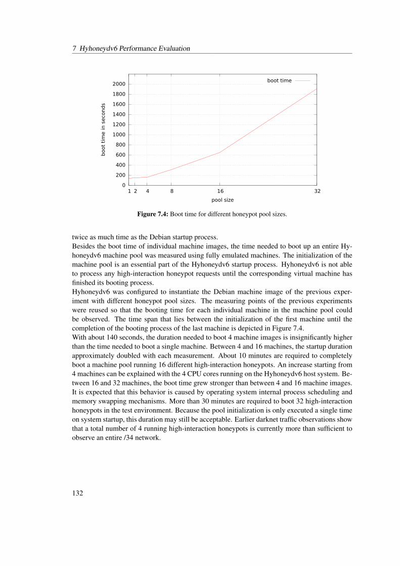
7 Hyhoneydv6 Performance Evaluation
0
200
400
600
800
1000
1200
1400
1600
1800
2000
1 2 4 8 16 32
boot
tim
e in s
eco
nd
s
pool size
boot time
Figure 7.4: Boot time for different honeypot pool sizes.
twice as much time as the Debian startup process.Besides the boot time of individual machine images, the time needed to boot up an entire Hy-honeydv6 machine pool was measured using fully emulated machines. The initialization of themachine pool is an essential part of the Hyhoneydv6 startup process. Hyhoneydv6 is not ableto process any high-interaction honeypot requests until the corresponding virtual machine hasfinished its booting process.Hyhoneydv6 was configured to instantiate the Debian machine image of the previous exper-iment with different honeypot pool sizes. The measuring points of the previous experimentswere reused so that the booting time for each individual machine in the machine pool couldbe observed. The time span that lies between the initialization of the first machine until thecompletion of the booting process of the last machine is depicted in Figure 7.4.With about 140 seconds, the duration needed to boot 4 machine images is insignificantly higherthan the time needed to boot a single machine. Between 4 and 16 machines, the startup durationapproximately doubled with each measurement. About 10 minutes are required to completelyboot a machine pool running 16 different high-interaction honeypots. An increase starting from4 machines can be explained with the 4 CPU cores running on the Hyhoneydv6 host system. Be-tween 16 and 32 machines, the boot time grew stronger than between 4 and 16 machine images.It is expected that this behavior is caused by operating system internal process scheduling andmemory swapping mechanisms. More than 30 minutes are required to boot 32 high-interactionhoneypots in the test environment. Because the pool initialization is only executed a single timeon system startup, this duration may still be acceptable. Earlier darknet traffic observations showthat a total number of 4 running high-interaction honeypots is currently more than sufficient toobserve an entire /34 network.
132
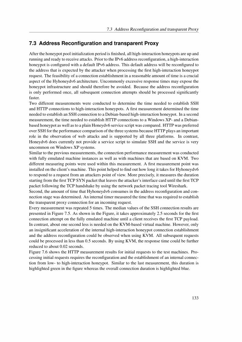
7.3 Address Reconfiguration and transparent Proxy
7.3 Address Reconfiguration and transparent Proxy
After the honeypot pool initialization period is finished, all high-interaction honeypots are up andrunning and ready to receive attacks. Prior to the IPv6 address reconfiguration, a high-interactionhoneypot is configured with a default IPv6 address. This default address will be reconfigured tothe address that is expected by the attacker when processing the first high-interaction honeypotrequest. The feasibility of a connection establishment in a reasonable amount of time is a crucialaspect of the Hyhoneydv6 architecture. Uncommonly excessive response times may expose thehoneypot infrastructure and should therefore be avoided. Because the address reconfigurationis only performed once, all subsequent connection attempts should be processed significantlyfaster.Two different measurements were conducted to determine the time needed to establish SSHand HTTP connections to high-interaction honeypots. A first measurement determined the timeneeded to establish an SSH connection to a Debian-based high-interaction honeypot. In a secondmeasurement, the time needed to establish HTTP connections to a Windows XP- and a Debian-based honeypot as well as to a plain Honeydv6 service script was compared. HTTP was preferredover SSH for the performance comparison of the three systems because HTTP plays an importantrole in the observation of web attacks and is supported by all three platforms. In contrast,Honeydv6 does currently not provide a service script to simulate SSH and the service is veryuncommon on Windows XP systems.Similar to the previous measurements, the connection performance measurement was conductedwith fully emulated machine instances as well as with machines that are based on KVM. Twodifferent measuring points were used within this measurement. A first measurement point wasinstalled on the client’s machine. This point helped to find out how long it takes for Hyhoneydv6to respond to a request from an attackers point of view. More precisely, it measures the durationstarting from the first TCP SYN packet that leaves the attacker’s interface card until the first TCPpacket following the TCP handshake by using the network packet tracing tool Wireshark.Second, the amount of time that Hyhoneydv6 consumes in the address reconfiguration and con-nection stage was determined. An internal timer measured the time that was required to establishthe transparent proxy connection for an incoming request.Every measurement was repeated 5 times. The median values of the SSH connection results arepresented in Figure 7.5. As shown in the Figure, it takes approximately 2.5 seconds for the firstconnection attempt on the fully emulated machine until a client receives the first TCP payload.In contrast, about one second less is needed on the KVM-based virtual machine. However, onlyan insignificant acceleration of the internal high-interaction honeypot connection establishmentand the address reconfiguration could be observed when using KVM. All subsequent requestscould be processed in less than 0.5 seconds. By using KVM, the response time could be furtherreduced to about 0.02 seconds.Figure 7.6 shows the HTTP measurement results for initial requests to the test machines. Pro-cessing initial requests requires the reconfiguration and the establishment of an internal connec-tion from low- to high-interaction honeypot. Similar to the last measurement, this duration ishighlighted green in the figure whereas the overall connection duration is highlighted blue.
133

7 Hyhoneydv6 Performance Evaluation
��
����
��
����
��
����
��
����
���������� ����������� ��������������� ����������������
�����������������������������
������������
���������������������������������������������
�����
��������
Figure 7.5: Time needed to establish an SSH connection to a Debian-based high-interaction honey-pot.
��
��
��
��
��
��
��
��
��
����������
�����������
�������
�����
�����������
�������
�����
�����������
������������
�����������������������������
�����
��������
Figure 7.6: Time needed to establish the first HTTP connections.
In case of the virtual machine-based high-interaction honeypots, the reconfiguration consumesmost of the required total time. As expected, a request to the plain Honeydv6 HTTP servicescript is significantly faster than the requests targeting the virtual machines. It does not requireany machine reconfiguration and takes about 18 milliseconds to deliver the first HTTP pay-load. Furthermore, the connection establishment to Debian-based machines is faster then theestablishment to Windows XP-based machines. The time needed for an initial connection to aDebian-based machines is about two seconds. A KVM-based Windows XP machine requires at
134
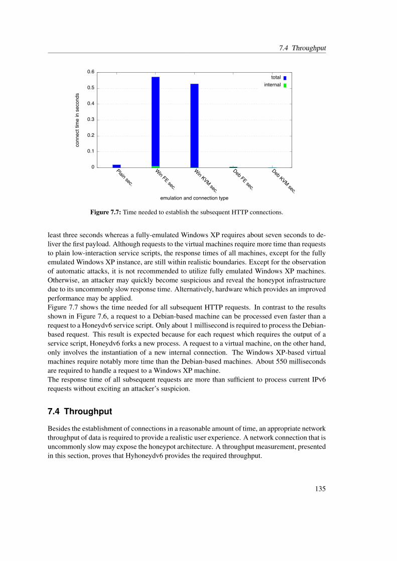
7.4 Throughput
��
����
����
����
����
����
����
����������
�����������
�������
�����
�����������
�������
�����
�����������
������������
�����������������������������
�����
��������
Figure 7.7: Time needed to establish the subsequent HTTP connections.
least three seconds whereas a fully-emulated Windows XP requires about seven seconds to de-liver the first payload. Although requests to the virtual machines require more time than requeststo plain low-interaction service scripts, the response times of all machines, except for the fullyemulated Windows XP instance, are still within realistic boundaries. Except for the observationof automatic attacks, it is not recommended to utilize fully emulated Windows XP machines.Otherwise, an attacker may quickly become suspicious and reveal the honeypot infrastructuredue to its uncommonly slow response time. Alternatively, hardware which provides an improvedperformance may be applied.Figure 7.7 shows the time needed for all subsequent HTTP requests. In contrast to the resultsshown in Figure 7.6, a request to a Debian-based machine can be processed even faster than arequest to a Honeydv6 service script. Only about 1 millisecond is required to process the Debian-based request. This result is expected because for each request which requires the output of aservice script, Honeydv6 forks a new process. A request to a virtual machine, on the other hand,only involves the instantiation of a new internal connection. The Windows XP-based virtualmachines require notably more time than the Debian-based machines. About 550 millisecondsare required to handle a request to a Windows XP machine.The response time of all subsequent requests are more than sufficient to process current IPv6requests without exciting an attacker’s suspicion.
7.4 Throughput
Besides the establishment of connections in a reasonable amount of time, an appropriate networkthroughput of data is required to provide a realistic user experience. A network connection that isuncommonly slow may expose the honeypot architecture. A throughput measurement, presentedin this section, proves that Hyhoneydv6 provides the required throughput.
135
7 Hyhoneydv6 Performance Evaluation
0
50
100
150
200
250
300
350
400
FE KVM
req
uest
s /
seco
nd
high-interaction honeypot virtualization type
Figure 7.8: Transparent HTTP requests/second.
The Apache webserver httpd1 was installed on a Debian high-interaction honeypot and the pub-licly available service benchmark servload version 0.9 [ZHS12] was used to measure the numberof http requests that Hyhoneydv6 is able to process with an opened connection. A single Debianmachine instance was booted and servload was configured to request the default httpd test pageup to 400 times per second.Figure 7.8 shows the measurement results. The fully emulated Debian machine was able to pro-cess 200 requests per second while the KVM-based machine could process about 320 requestsper second which is more than sufficient for the current threat level in IPv6 networks.
7.5 Summary
This section presented the performance measurement results of the Hyhoneydv6 prototype im-plementation. The results show that Hyhoneydv6 performs better than required by the currentthreat level in IPv6 networks, even on off-the-shelf hardware. An initial startup with four high-interaction honeypots could be accomplished in slightly more than two minutes. Within aboutten minutes, a machine pool with sixteen different high-interaction honeypot instances could bestarted successfully.With one exception, the transparent proxy implementation was able to establish connectionswithin an acceptable time even on fully emulated machines. An SSH connection to a fully emu-lated Debian honeypot could be established in about 2.5 seconds. By using a KVM-based virtualmachine, the connection time could be further reduced to about 1.5 seconds. A fully emulatedWindows XP, however, requires improved hardware to provide a realistic attack environment.On an established connection, the proxy implementation could handle about 200 requests evenon a fully emulated machine, which should be more than sufficient for most IPv6 honeypot usecases.
1https://httpd.apache.org
136
8 Conclusion and Future Work
This thesis revealed several new challenges that appear in the context of IPv6 honeypot develop-ments. Darknet observations confirm that attackers scan large and unpredictable address spaceswhen searching for new hosts in IPv6 networks. Modern IPv6 honeypot architectures thereforedemand new architectural approaches, such as sophisticated honeypot distribution strategies.The honeypot survey presented in the first part of this thesis has shown that there is currently nota single architecture for the observation of large-scale IPv6 network attacks available.This thesis proposes two new honeypot architectures, called Honeydv6 and Hyhoneydv6, to fillthe gap of available honeypot solutions for large IPv6 networks. Section 8.1 presents a shortsummary of both honeypot architectures, the conducted honeypot survey and the results fromtwo long-term darknet experiments. Section 8.2 explains how future IPv6 network securityresearch can benefit from these contributions.
8.1 Research Contributions
This thesis makes the following contributions to the research area of IPv6 honeypots:
IPv6 Attack Classification: A classification that is based on the Common Vulnerability ScoringSystem Version 2 (CVSSv2) categorizes currently known remote IPv6 attacks [MSR07].The classification includes attacks on IPv6 extension headers, fragmentation mechanismsand the IPv6 Flow Label. Besides the basic CVSSv2 metrics, the classification providesan overall score, effect, type and status to further describe an attack.
Honeypot Survey: In a survey of ten different major honeypot architectures were examined fortheir applicability in IPv6 networks. Besides basic IPv6 functionality, the survey con-sidered whether the architectures implement a dynamic honeypot instantiation and IP ad-dress configuration mechanism to provide an authentic attack environment. Furthermore,it was determined if and how the architectures provide support for the handling of net-work scans. The survey revealed that only one of the ten examined architectures explicitlysupports IPv6 networks. However, this architecture is limited to 64-bit large networksand can therefore not be applied within larger address spaces, such as the /34 space usedin the presented darknet experiment. All other architectures do either not implement anyIPv6 functionality or their authors do not provide any information about the deploymentin IPv6 networks. Furthermore, the survey has shown that, prior to this thesis, there wereno honeypot solutions with support for all examined features available.
Honeydv6: Honeydv6 is one of two IPv6 honeypot architectures proposed in this thesis. Itis a low-interaction honeypot architecture which extends the well-known IPv4 honey-pot Honeyd [Pro04]. Honeydv6 implements a customized IPv6 network stack, including
137
8 Conclusion and Future Work
basic ICMPv6 and Neighbor Discovery (ND) protocol functionality, which runs com-pletely in user-space. By evaluating the IPv6 fingerprinting database of the Nmap securityscanner [FGM+15], Honeydv6 is able to mimic various operating systems. The customnetwork stack allows the simulation of entire IPv6 networks on a single machine andthe observation of low-level IPv6 attacks. Honeydv6 encounters the vast IPv6 addressspace with a dynamic instantiation mechanism for low-interaction honeypots. Based onan attacker’s target, Honeydv6 dynamically spawns new low-interaction honeypots on-demand. One major advantage of this mechanism is that it can cover large IPv6 addressspaces without relying on an understanding about an attacker’s scan approaches.
Hyhoneydv6: One disadvantage of Honeydv6 is that its service scripts can only mock servicesup to a certain level of granularity. This thesis proposes the Hyhoneydv6 architectureto overcome this limitation. A combination of low- and high-interaction honeypots al-lows Hyhoneydv6 to provide the same flexibility as Honeydv6 while providing genuinenetwork services. Network scans or attacks to less sophisticated network services arehandled by low-interaction honeypots while attacks to complex network services are pro-cessed by high-interaction honeypots. Hyhoneydv6 implements a high-interaction honey-pot manager which maintains a pool of virtual machine-based high-interaction honeypots.The high-interaction honeypot manager utilizes an address reconfiguration server and anewly developed proxy implementation to transparently forward attackers from low- tohigh-interaction honeypots. Performance measurements of the Hyhoneydv6 prototype im-plementation prove that the architecture can cover entire IPv6 networks on off-the-shelfhardware.
Darknet Observations: A 9-months /48 and a 17-months /34 darknet were deployed to deter-mine the current threat level in IPv6 networks. The traffic rate of both IPv6 networks wasstill relatively low compared to the rate that can be observed in IPv4 networks. However, itcan be concluded that IPv6 networks are not free of unintended activity. The 9-months /48darknet captured a lot of backscatter traffic, caused by spoofed source addresses, whichappears to belong to denial of service attacks. The /34 darknet experiment revealed manylarge-scale network scans which applied different scan patterns to find hosts in differentand mostly unpredictable address spaces. With the support of Honeydv6-based active re-sponders, it could be shown that different sources appear to share their scan results andrepeatedly contact discovered hosts. A majority of the observed network scans, however,seems to belong to research institutions and organizations which try to gather informationabout current IPv6 deployments.
138
8.2 Future Work
8.2 Future Work
This thesis makes important contributions to the research field of IPv6 network security. Thepresented honeypot architectures enable new ways to monitor IPv6 network attacks and to re-veal and analyze new vulnerabilities. Existing and future honeypot projects which are currentlyrestricted to IPv4 networks can profit from the proposed concepts and their prototype implemen-tations. Furthermore, researchers can benefit from the observations that were made within thescope of two long-term darknet observations presented in this thesis. The captured scan patternsand the processed traffic statistics support future honeypot designers to adjust their architecturesaccording to IPv6 network requirements. A selection of new sources for future research arepresented in the following subsections.
8.2.1 Update Honeyd-based Projects
Honeyd [Pro04] is a honeypot framework that has been used as a foundation for many otherhoneypot architectures. Honeybrid [Ber09], Honey@home [AAM07] and the hybrid system forwireless mesh networks [RGAS12], which were also evaluated in the scope of this thesis, arethree examples for Honeyd-based architectures. These projects can benefit from Honeydv6’snewly implemented IPv6 network stack. Besides being able to process IPv6 network traffic,Honeydv6’s dynamic honeypot instantiation mechanism prepares a foundation for entirely newfeatures and ways to observe IPv6 network attacks.Honeydv6 provides a superset of Honeyd’s features and does not change the IPv4 configurationsyntax. Therefore, honeypot projects which are based on Honeyd can easily use Honeydv6 asa replacement. However, depending on the project, it may be necessary to update upper layerservices or infrastructure components, such as logging facilities, to work with IPv6 addresses.
8.2.2 Real-World Attack Observations and Honeypot Parameter Tuning
The darknet observations presented in Chapter 5 have shown that the threat level in IPv6 net-works is still very low compared to the threat level in IPv4 networks. It can be expected that thissituation will change with the increase of accessible network devices and the decrease of avail-able IPv4 addresses. Honeydv6 and Hyhoneydv6 were subject to multiple performance testswhich required the processing of a huge amount of network traffic. Furthermore, Honeydv6 wasdeployed as an active responder in a long-term darknet experiment. However, there are no re-sults from Honeydv6 and Hyhoneydv6 deployments in highly-loaded real-world IPv6 networksavailable. Future IPv6 traffic and attacks, however, play an important role when it comes to thedefinition of honeypot configuration parameters. Optimal values for the dynamic instantiationof honeypots or the Hyhoneydv6 pool size still have to be found. A machine pool size of about4 machines is more than sufficient to handle the current amount of IPv6 network traffic even inlarge IPv6 networks. However, an optimal value that is able to handle tomorrow’s IPv6 networktraffic is currently unknown. Future IPv6 honeypot experiments may deliver these results onceIPv6 is the dominating protocol in the global Internet.
139
8 Conclusion and Future Work
8.2.3 Large-Scale Darknet Experiments
Chapter 5 revealed that the level and the kind of network traffic can differ sharply betweendifferent IPv6 address spaces. These and prior darknet experiments, such as the experiments byCzyz et al. [CLM+13] and Geoff Huston [Hus10], observed relatively small chunks of addressspace compared to the vast space that IPv6 has to offer. Future experiments should observelarger IPv6 address spaces in order to gain a more comprehensive picture of the activities in IPv6networks. The honeynet project1 set up an infrastructure called HoneyMap, which visualizes theresults of a collaboration of honeypots. Future IPv6 traffic experiments may adopt this approachand allow a collaboration of a large number of independent darknets to increase the observationcoverage and to learn about different characteristics in different IPv6 address spaces.
8.3 Final Words
The expensive acquisition of remaining IPv4 address spaces and techniques, such as networkaddress translation, have supported the circumvention of an extensive IPv6 deployment withinthe last few years. However, this situation is about to change and Internet Service Providers(ISPs) are more and more requested to prepare the way for the IPv6. Certainly, it is only amatter of time until IPv6 represents a majority in global traffic statistics. It can be expected thatthe number of attacks in IPv6 networks increases with the expansion of the IPv4 successor. Thecontributions of this thesis can support the analyses of future IPv6 network attacks and help todevelop the required countermeasures.
1https://www.honeynet.org
140
A Creating Virtual Machine Images forHyhoneydv6
Hyhoneydv6 can cover large IPv6 address spaces with high-interaction honeypots. The high-interaction honeypots must be provided in form of virtual machine images. Hyhoneydv6 sup-ports various operating systems. One requirement is that the operating system is able to run thedynamic Hyhoneydv6 address configuration server. The server is written in Python to supportall major operating systems, such as Windows and Linux.Hyhoneydv6 utilizes the virtualization API libvirt[Lib15] to control the instantiation, backupand destruction of high-interaction honeypots. libvirt supports various virtualization solutions,e.g. Xen, VirtualBox or KVM/QEMU. This chapter describes how new QEMU machine imagescan be created and integrated into a Hyhoneydv6 honeypot environment.
QEMU Installation: This step depends on the operating system on which Hyhoneydv6 is run-ning on. Most major Linux distributions provide QEMU packages. It is possible to com-pile QEMU from its sources which are provided on the official QEMU website1.
QEMU Base Hard Disk Image Creation: Hyhoneydv6 makes a copy of the hard disk for everynew machine that has to be dynamically created. To avoid copying entire hard disk imagesand to save memory on the host system, it is recommended to create one base image perhigh-interaction honeypot operating system. The base image can be used later to createmultiple copy-on-write images. A copy-on-write image only stores changes made to thebase image. It is smaller compared to the base image and therefore faster to copy andto backup. The hard disk for the QEMU base image can be created with the followingcommand: QEMU-img create -f qcow2 base.img 10G.
Operating System Installation: After creating the base image hard disk, a machine using thenewly created hard disk can be started with the command QEMU-system-i386 -m 256 -hda base.img -cdrom cdrom-with-os.iso -boot d. The next required step is the installationof the operating system for the high-interaction honeypot which should be located on theprovided cdrom disk image file. The actual installation process depends on the operatingsystem that is going to be installed.
Honeypot Network Configuration: Hyhoneydv6 uses a network bridge to communicate withthe high-interaction honeypots. Details about the network configuration can be found inthe Hyhoneydv6 network configuration file hihs/xmls/honeynetwork.xml. By default, thenetwork is configured to assign IPv6 addresses via DHCPv6. If the installed operating sys-tem does not support DHCPv6, e.g. Windows XP, then a static address can be configured.
1http://wiki.qemu.org/
141
A Creating Virtual Machine Images for Hyhoneydv6
Although the static IPv6 address is only active until the first IPv6 address reconfigura-tion is finished, it is recommended to choose different static IPv6 addresses for differentmachine images in order to avoid network address conflicts.
Dynamic IPv6 Configuration Server Installation: Hyhoneydv6 is able to dynamically recon-figure IPv6 addresses of the virtual high-interaction machine images. The reconfigurationis done by the IPv6 address configuration server that is running on the high-interactionhoneypots until the address configuration has finished. The configuration server is writtenin Python so that a Python interpreter needs to be installed on the high-interaction hon-eypot operating system. When Python is successfully installed, the configuration serverneeds to be copied to the high-interaction honeypot. The address configuration serverneeds to be started automatically with the high-interaction honeypot boot process. Anautostart configuration depends on the type of operating system. A Linux reconfigurationserver, for example, requires a corresponding init script.
Copy-On-Write Image Creation: After the base image has successfully been created, the fol-lowing command can be used to create a copy-on-write image: QEMU-img create -bbase.img -f qcow2 base-clone.img. The copy-on-write images will only store the changesmade to the base image. It is therefore important to note that all changes to the base imagerequire a recreation of the assigned copy-on-write images.
Honeypot XML Definition: For each high-interaction honeypot booting process, Hyhoneydv6sends a machine description in form of an XML file to libvirt. The description containsinformation about the amount of memory, the number of processors, the hard disk imagefile, the network configuration, the virtualization solution etc. An example XML descrip-tion is provided in Appendix B. A new XML description for the honeypot has to be createdbefore Hyhoneydv6 can be configured to run a new high-interaction honeypot. In orderto simplify this process, Hyhoneydv6 provides an example file called example_hih.xml.This sample file can be used as a template for new configurations. For most cases, it issufficient to adapt the the hard disk source in the devices section, the amount of neededmemory as well as the name of the honeypot. Some of the values are redefined by Hy-honeydv6 and therefore can not be configured manually, e.g. the VNC port, the UUID orthe mac address. More details about the possible configuration parameters can be foundin documentation that is available on the official libvirt website2.
Honeypot Integration into Hyhoneydv6 Configuration: The XML configuration that was cre-ated in the previous step can be added to the Hyhoneydv6 configuration file by using thehih statement. For example, a machine called linux with an XML configuration calledlinux.xml can be created by using the statement hih linux hihs/xmls/linux.xml. Aconfiguration that transparently forwards an SSH connection to this newly defined ma-chine can then be configured using the statement add template tcp port 22 proxytransparent linux.
2https://libvirt.org
142
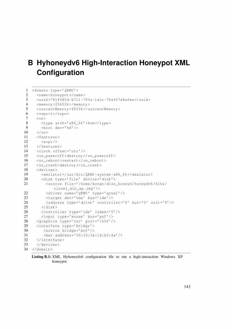
B Hyhoneydv6 High-Interaction Honeypot XMLConfiguration
1 <domain type=’QEMU ’>2 <name >honeypot </name >3 <uuid >7816585d-b711 -703a-1a1c -78e557e8afea </uuid >4 <memory >256536</memory >5 <currentMemory >65536</currentMemory >6 <vcpu >1</vcpu >7 <os>8 <type arch=’x86_64 ’>hvm </type >9 <boot dev=’hd’/>
10 </os>11 <features >12 <acpi/>13 </features >14 <clock offset=’utc ’/>15 <on_poweroff >destroy </on_poweroff >16 <on_reboot >restart </on_reboot >17 <on_crash >destroy </on_crash >18 <devices >19 <emulator >/usr/bin/QEMU -system -x86_64 </emulator >20 <disk type=’file ’ device=’disk ’>21 <source file=’/home/bongo/diss_honeyd/honeydv6/hihs/
clone1_win_xp.img ’/>22 <driver name=’QEMU ’ type=’qcow2 ’/>23 <target dev=’hda’ bus=’ide ’/>24 <address type=’drive ’ controller=’0’ bus=’0’ unit=’0’/>25 </disk >26 <controller type=’ide’ index=’0’/>27 <input type=’mouse ’ bus=’ps2 ’/>28 <graphics type=’vnc’ port=’1056’/>29 <interface type=’bridge ’>30 <source bridge=’br0 ’/>31 <mac address=’00:16:3e:1d:b3:4a’/>32 </interface >33 </devices >34 </domain >
Listing B.1: XML Hyhoneydv6 configuration file to run a high-interaction Windows XPhoneypot.
143

B Hyhoneydv6 High-Interaction Honeypot XML Configuration
144
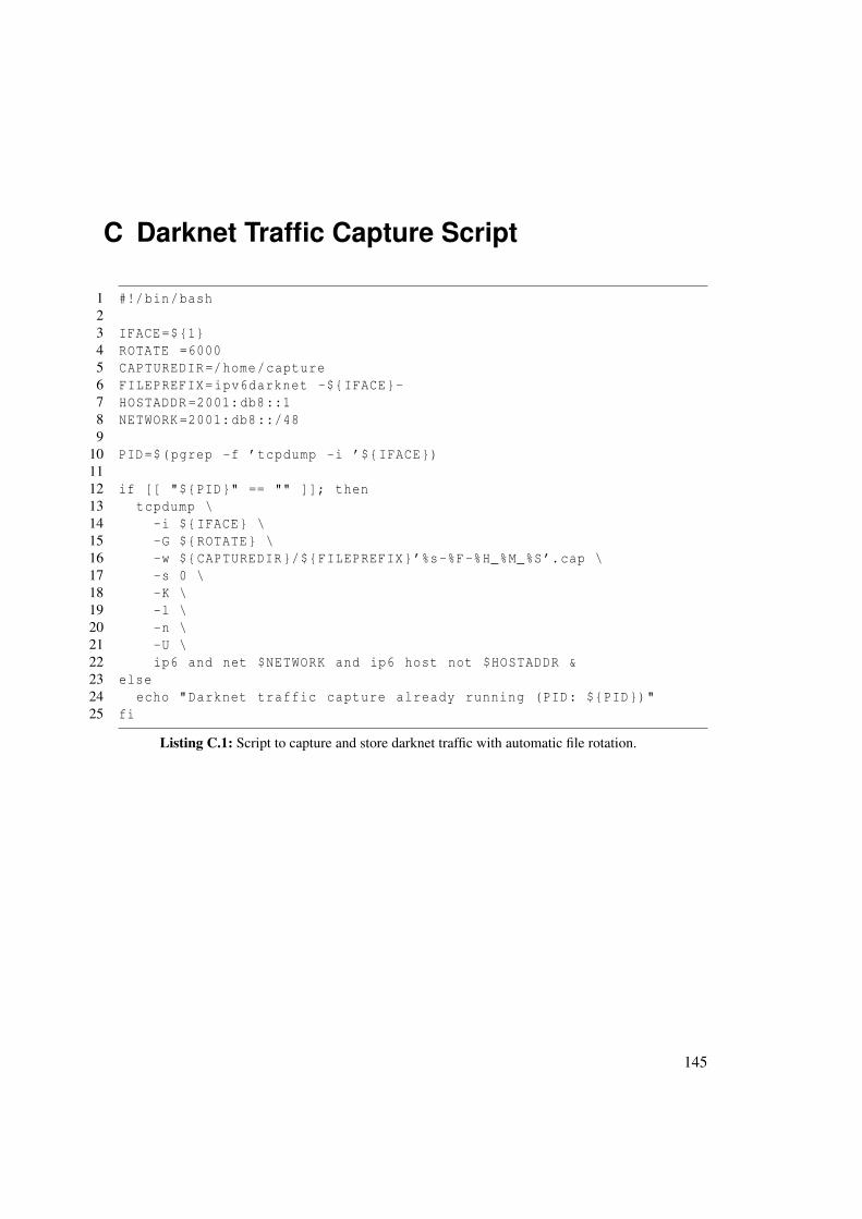
C Darknet Traffic Capture Script
1 #!/bin/bash23 IFACE=${1}4 ROTATE =60005 CAPTUREDIR=/home/capture6 FILEPREFIX=ipv6darknet -${IFACE}-7 HOSTADDR =2001:db8::18 NETWORK =2001:db8::/489
10 PID=$(pgrep -f ’tcpdump -i ’${IFACE})1112 if [[ "${PID}" == "" ]]; then13 tcpdump \14 -i ${IFACE} \15 -G ${ROTATE} \16 -w ${CAPTUREDIR}/${FILEPREFIX}’%s-%F-%H_%M_%S’.cap \17 -s 0 \18 -K \19 -l \20 -n \21 -U \22 ip6 and net $NETWORK and ip6 host not $HOSTADDR &23 else24 echo "Darknet traffic capture already running (PID: ${PID})"25 fi
Listing C.1: Script to capture and store darknet traffic with automatic file rotation.
145

C Darknet Traffic Capture Script
146
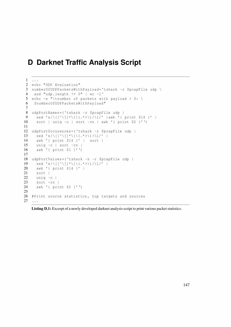
D Darknet Traffic Analysis Script
1 ...2 echo "UDP Evaluation"3 numberOfUDPPacketsWithPayload=‘tshark -r $pcapFile udp \4 and "udp.length != 0" | wc -l‘5 echo -e "\tnumber of packets with payload > 0: \6 $numberOfUDPPacketsWithPayload"78 udpPortNames=(‘tshark -r $pcapFile udp |9 sed ’s/\[[^\[]*\]\(.* >\)/\1/’ |awk ’{ print $14 }’ |
10 sort | uniq -c | sort -rn | awk ’{ print $2 }’‘)1112 udpPortOccurences=(‘tshark -r $pcapFile udp |13 sed ’s/\[[^\[]*\]\(.* >\)/\1/’ |14 awk ’{ print $14 }’ | sort |15 uniq -c | sort -rn |16 awk ’{ print $1 }’‘)1718 udpPortValues=(‘tshark -n -r $pcapFile udp |19 sed ’s/\[[^\[]*\]\(.* >\)/\1/’ |20 awk ’{ print $14 }’ |21 sort |22 uniq -c |23 sort -rn |24 awk ’{ print $2 }’‘)2526 #Print source statistics , top targets and sources27 ...
Listing D.1: Excerpt of a newly developed darknet analysis script to print various packet statistics.
147

D Darknet Traffic Analysis Script
148

E Abbreviations
ARIN American Registry for Internet Numbers
ARP Address Resolution Protocol
AS Autonomous System
BGP Border Gateway Protocol
CAIDA Center for Applied Internet Data Analysis
CDN content delivery network
COW copy-on-write
CPE Common Platform Enumeration
CVSSv2 Common Vulnerability Scoring System Version 2
DHCP Dynamic Host Configuration Protocol
DoS denial-of-service
EC2 Elastic Compute Cloud
ECN Explicit Congestion Notification
ENISA European Network and Information Security Agency
EUI Extended Unique Identifier
IANA Internet Assigned Numbers Authority
ICMPv6 Internet Control Message Protocol for the Internet Protocol Version 6
ICS Industrial Control System
IDS intrusion detection system
IP Internet Protocol
IPv4 Internet Protocol version 4
IPv6 Internet Protocol version 6
149
E Abbreviations
ISC Internet Systems Consortium
ISP Internet Service Provider
KVM Kernel-based Virtual Machine
MTU Maximum Transmission Unit
NAT network address translation
ND Neighbor Discovery
NIC network interface controller
OUI Organizationally Unique Identifier
RDP Remote Desktop Protocol
RIR Regional Internet Registry
RPC remote procedure call
SIIT Stateless IP/ICMP Translation
SIT Simple Internet Transition
SLAAC Stateless Address Autoconfiguration
SMB Server Message Block
UML User Mode Linux
UUID universally unique identifier
VLAN virtual local area network
VNC Virtual Network Computing
150

Bibliography
[AAM07] Spiros Antonatos, Kostas Anagnostakis, and Evangelos Markatos. Honey@Home:A New Approach to Large-scale Threat Monitoring. In Proceedings of the 2007 ACMWorkshop on Recurring Malcode, WORM ’07, pages 38–45, New York, NY, USA,2007. ACM.
[ACJR11] S. Amante, B. Carpenter, S. Jiang, and J. Rajahalme. IPv6 Flow Label Specification.RFC 6437 (Proposed Standard), November 2011.
[Ame15] American Registry for Internet Numbers. Waiting list for unmet requests, October2015. https://www.arin.net/resources/request/waiting_list.html.
[ASJH99] G. Armitage, P. Schulter, M. Jork, and G. Harter. IPv6 over Non-Broadcast MultipleAccess (NBMA) networks. RFC 2491 (Proposed Standard), January 1999.
[ASNN07] J. Abley, P. Savola, and G. Neville-Neil. Deprecation of Type 0 Routing Headers inIPv6. RFC 5095 (Proposed Standard), December 2007.
[Atl12] A. Atlasis. Attacking IPv6 Implementation Using Fragmentation. In Black Hat Eu-rope, March 2012.
[BBEN07] Jay Beale, Andrew R. Baker, Joel Esler, and Stephen Northcutt. Snort: IDS and IPStoolkit. Jay Beale’s open source security series. Syngress, 2007.
[BCJ+06] Michael Bailey, Evan Cooke, Farnam Jahanian, Andrew Myrick, and Sushant Sinha.Practical Darknet Measurement. In Proceedings of the 40th Annual Conference onInformation Sciences and Systems (CISS ’06), pages 1496–1501, Princeton, New Jer-sey, USA, March 2006.
[BCW+04] Michael D. Bailey, Evan Cooke, David Watson, Farnam Jahanian, and Niels Provos.A Hybrid Honeypot Architecture for Scalable Network Monitoring. Technical ReportCSE-TR-499-04, University of Michigan, Ann Arbor, Michigan, USA, October 2004.
[BDH99] D. Borman, S. Deering, and R. Hinden. IPv6 Jumbograms. RFC 2675 (ProposedStandard), August 1999.
[Bel05] Fabrice Bellard. QEMU, a Fast and Portable Dynamic Translator. In Proceedings ofthe Annual Conference on USENIX Annual Technical Conference, ATEC ’05, pages41–41, Berkeley, CA, USA, 2005. USENIX Association.
151
Bibliography
[Ber09] Robin G. Berthier. Advanced honeypot architecture for network threats quantifica-tion. PhD thesis, University of Maryland, University of Maryland, College Park, MD,USA, 2009. AAI3359256.
[Bio07] Biondi, P. and A. Ebalard. IPv6 Routing Header Security. http://www.secdev.org/conf/IPv6_RH_security-csw07.pdf, April 2007. [Online; accessed 29-June-2015].
[BM03] Andrei Broder and Michael Mitzenmacher. Network Applications of Bloom Filters:A Survey. Internet Math., 1(4):485–509, 2003.
[CDG06] A. Conta, S. Deering, and M. Gupta. Internet Control Message Protocol (ICMPv6)for the Internet Protocol Version 6 (IPv6) Specification. RFC 4443 (Draft Standard),March 2006. Updated by RFC 4884.
[CH06] M. Crawford and B. Haberman. IPv6 Node Information Queries. RFC 4620 (Exper-imental), August 2006.
[CH13] S. Chatterjee and A.S. Hadi. Regression Analysis by Example. Wiley Series in Prob-ability and Statistics. Wiley, 5th edition, 2013.
[Cho08] T. Chown. IPv6 Implications for Network Scanning. RFC 5157 (Informational),March 2008.
[CLM+13] Jakub Czyz, Kyle Lady, Sam G. Miller, Michael Bailey, Michael Kallitsis, and Man-ish Karir. Understanding IPv6 Internet Background Radiation. In Proceedings of the2013 Conference on Internet Measurement Conference, IMC ’13, pages 105–118,New York, NY, USA, 2013. ACM.
[CLRC12] Patrice Clemente, Jean-François Lalande, and Jonathan Rouzaud-Cornabas. Hon-eyCloud: elastic honeypots - On-attack provisioning of high-interaction honeypots.In International Conference on Security and Cryptography, pages 434–439, Rome,Italy, July 2012.
[CPW06] Weidong Cui, Vern Paxson, and Nicholas C. Weaver. GQ: Realizing a System toCatch Worms in a Quarter Million Places. ICSI Technical Report TR-06-004, Uni-versity of California, Berkeley, CA, September 2006.
[CPWK06] Weidong Cui, Vern Paxson, Nicholas Weaver, and Randy H. Katz. Protocol-Independent Adaptive Replay of Application Dialog. In Proceedings of the 13thAnnual Network and Distributed System Security Symposium (NDSS), February 2006.
[CWS11] Brant A. Cheikes, David Waltermire, and Karen Scarfone. Common Platform Enu-meration: Naming Specification Version 2.3. National Institute of Standards andTechnology, Maryland, USA, 2011.
[DH95] S. Deering and R. Hinden. Internet Protocol, Version 6 (IPv6) Specification. RFC1883 (Proposed Standard), December 1995. Obsoleted by RFC 2460.
152
Bibliography
[DH98] S. Deering and R. Hinden. Internet Protocol, Version 6 (IPv6) Specification. RFC2460 (Draft Standard), December 1998. Updated by RFCs 5095, 5722, 5871, 6437,6564, 6935, 6946, 7045, 7112.
[DHJ+05] S. Deering, B. Haberman, T. Jinmei, E. Nordmark, and B. Zill. IPv6 Scoped AddressArchitecture. RFC 4007 (Proposed Standard), March 2005. Updated by RFC 7346.
[Dio14] dionaea catches bugs, Accessed August, 2014. http://dionaea.carnivore.it/.
[DNS14] DNSchef, November 2014. https://thesprawl.org/projects/dnschef/.
[Dug15] Dug Song. Libdnet, Accessed November, 2015. http://libdnet.sourceforge.net.
[DWH13] Zakir Durumeric, Eric Wustrow, and J. Alex Halderman. ZMap: Fast Internet-wideScanning and Its Security Applications. In 22nd USENIX Security Symposium, pages605–620, Washington, D.C., 2013. USENIX.
[FGM+99] R. Fielding, J. Gettys, J. Mogul, H. Frystyk, L. Masinter, P. Leach, and T. Berners-Lee. Hypertext Transfer Protocol – HTTP/1.1. RFC 2616 (Draft Standard), June1999. Obsoleted by RFCs 7230, 7231, 7232, 7233, 7234, 7235, updated by RFCs2817, 5785, 6266, 6585.
[FGM+15] David Fifield, Alexandru Geana, Luis MartinGarcia, Mathias Morbitzer, and J.D.Tygar. Remote Operating System Classification over IPv6. In Proceedings of the 8thACM Workshop on Artificial Intelligence and Security, AISec ’15, pages 57–67, NewYork, NY, USA, 2015. ACM.
[Fri14] Christian Frieben. IPv6 im Wandel Analyse der IPv6-Standardisierung unter Sicher-heitsaspekten. Master’s thesis, University of Potsdam, Germany, 2014.
[FSR06] Matthew Ford, Jonathan Stevens, and John Ronan. Initial Results from an IPv6 Dark-net. In ICISP ’06: Proceedings of the International Conference on Internet Surveil-lance and Protection, Washington, DC, USA, 2006. IEEE Computer Society.
[GC15] F. Gont and T. Chown. Network Reconnaissance in IPv6 Networks, August 2015.http://tools.ietf.org/html/draft-ietf-opsec-ipv6-host-scanning-08.
[Ger09] R. Gerhards. The Syslog Protocol. RFC 5424 (Proposed Standard), March 2009.
[GJJ+12] T. Grudziecki, P. Jacewicz, L. Juszczyk, P. Kijewski, and P. Pawlinski. ProactiveDetection of Security Incidents - Honeypots. Honeypot study, European Networkand Information Security Agency, November 2012.
[GL13] F. Gont and W. Liu. Security Implications of IPv6 Options ofType 10xxxxxx, March 2013. http://tools.ietf.org/html/draft-gont-6man-ipv6-smurf-amplifier-03.
153

Bibliography
[GLA14] F. Gont, W. Liu, and T. Anderson. Deprecating the Generation ofIPv6 Atomic Fragments, August 2014. https://tools.ietf.org/html/draft-ietf-6man-deprecate-atomfrag-generation-01.
[GMB14] F. Gont, V. Manral, and R. Bonica. Implications of Oversized IPv6 Header Chains.RFC 7112 (Proposed Standard), January 2014.
[Gon13] F. Gont. Processing of IPv6 "Atomic" Fragments. RFC 6946 (Proposed Standard),May 2013.
[Goo15] Google Inc. Google IPv6 - Statistics, October 2015. https://www.google.com/intl/en/ipv6/statistics.html.
[Gup03] Nirbhay Gupta. Is honeyd effective or not? In Australian Computer, Network & In-formation Forensics Conference. School of Computer and Information Science, EdithCowan University, Western Australia, 2003.
[Had02] Ibrahim Haddad. Linux IPv6: Which One to Deploy? Linux Journal, 2002(96):5–,April 2002.
[HD06] R. Hinden and S. Deering. IP Version 6 Addressing Architecture. RFC 4291 (DraftStandard), February 2006. Updated by RFCs 5952, 6052, 7136, 7346, 7371.
[Heu15] Marc Heuse. THC IPv6 Attack Tool Kit, Accessed November, 2015. http://www.thc.org/thc-ipv6/.
[Hon15] Project HoneyTrain. Technical report, Kotamis GmbH, Hans-Peter Fichtner andMichael Krammel, September 2015.
[HS01] M. Holdrege and P. Srisuresh. Protocol Complications with the IP Network AddressTranslator. RFC 3027 (Informational), January 2001.
[Hui06] C. Huitema. Teredo: Tunneling IPv6 over UDP through Network Address Transla-tions (NATs). RFC 4380 (Proposed Standard), February 2006. Updated by RFCs5991, 6081.
[Hus10] Geoff Huston. Background Radiation in IPv6, October 2010. https://labs.ripe.net/Members/mirjam/background-radiation-in-ipv6.
[Int15a] Internet Assigned Numbers Authority. Internet Protocol Version 6 Address Space,October 2015. http://www.iana.org/assignments/ipv6-address-space/ipv6-address-space.xhtml.
[Int15b] Internet Assigned Numbers Authority. Internet Protocol Version 6 (IPv6) Pa-rameters, July 2015. http://www.iana.org/assignments/ipv6-parameters/ipv6-parameters.xhtml.
154

Bibliography
[Int15c] Internet Assigned Numbers Authority. Service Name and Transport ProtocolPort Number Registry, November 2015. http://www.iana.org/assignments/service-names-port-numbers/service-names-port-numbers.xhtml.
[Int15d] Internet Society. IPv6 is the new normal, Accessed November, 2015. http://www.worldipv6launch.org.
[JBB92] V. Jacobson, R. Braden, and D. Borman. TCP Extensions for High Performance. RFC1323 (Proposed Standard), May 1992. Obsoleted by RFC 7323.
[JD04] Xuxian Jiang and Xuxian Jiang Dongyan. Collapsar: A VM-Based Architecturefor Network Attack Detention Center. In Proceedings of the 13th USENIX SecuritySymposium, SSYM’04, pages 15–28, San Diego, CA, 2004.
[Joh93] M. St. Johns. Identification Protocol. RFC 1413 (Proposed Standard), February 1993.
[Joh14] Johanna Ullrich and Katharina Krombholz and Heidelinde Hobel and AdrianDabrowski and Edgar Weippl. Ipv6 security: Attacks and countermeasures in a nut-shell. In 8th USENIX Workshop on Offensive Technologies (WOOT 14), San Diego,CA, 2014. USENIX Association.
[Jon10] M. Tim Jones. Anatomy of the libvirt virtualization library. IBM developer Works,pages 97–108, 2010.
[JXE04] Xuxian Jiang, Dongyan Xu, and R. Eigenmann. Protection mechanisms for applica-tion service hosting platforms. In Proceedings of the 2004 IEEE International Sympo-sium on Cluster Computing and the Grid, CCGRID ’04, pages 656–663, Washington,DC, USA, 2004. IEEE Computer Society.
[Kal00] C. Kalt. Internet Relay Chat: Architecture. RFC 2810 (Informational), April 2000.
[Ken05a] S. Kent. IP Authentication Header. RFC 4302 (Proposed Standard), December 2005.
[Ken05b] S. Kent. IP Encapsulating Security Payload (ESP). RFC 4303 (Proposed Standard),December 2005.
[Koh09] J. Kohlrausch. Experiences with the NoAH Honeynet Testbed to Detect new InternetWorms. In IT Security Incident Management and IT Forensics, 2009. IMF ’09. FifthInternational Conference on, pages 13–26, 2009.
[KOY+12] K. Kishimoto, K. Ohira, Y. Yamaguchi, H. Yamaki, and H. Takakura. An AdaptiveHoneypot System to Capture IPv6 Address Scans. In Cyber Security (CyberSecurity),2012 International Conference on, pages 165–172, Dec 2012.
[Kri09] S. Krishnan. Handling of Overlapping IPv6 Fragments. RFC 5722 (Proposed Stan-dard), December 2009. Updated by RFC 6946.
[KWK+12] S. Krishnan, J. Woodyatt, E. Kline, J. Hoagland, and M. Bhatia. A Uniform Formatfor IPv6 Extension Headers. RFC 6564 (Proposed Standard), April 2012.
155

Bibliography
[Lib15] libvirt - The virtualization API, Accessed November, 2015. http://libvirt.org.
[LJS10] Q. Li, T. Jinmei, and K. Shima. IPv6 Core Protocols Implementation. The MorganKaufmann Series in Networking. Elsevier Science, 2010.
[LNM+12] Tamas K. Lengyel, Justin Neumann, Steve Maresca, Bryan D. Payne, and Agge-los Kiayi. Virtual Machine Introspection in a Hybrid Honeypot Architecture. In5th Workshop on Cyber Security Experimentation and Test, Berkeley, CA, 2012.USENIX.
[Lyo11] Gordon Fyodor Lyon. Nmap Network Scanning: The Official Nmap Project Guide toNetwork Discovery and Security Scanning. Insecure, USA, 2011.
[McC15] James McCaffrey. Test Run - L1 and L2 Regularization for Machine Learning, Febru-ary 2015. https://msdn.microsoft.com/en-us/magazine/dn904675.aspx.
[MFHM15] Michael Müter, Felix Freiling, Thorsten Holz, and Jeanna Matthews. A GenericToolkit for Converting Web Applications Into High-Interaction Honeypots. http://people.clarkson.edu/~jmatthew/publications/honeypot-raid2007.pdf,Accessed July, 2015.
[Mic14] Michal Zalewski. p0f v3, 2014. http://lcamtuf.coredump.cx/p0f3/.
[Mic15a] Microsoft Corporation. IPv6 configuration methods, Accessed November,2015. https://www.microsoft.com/resources/documentation/windows/xp/all/proddocs/en-us/sag_ip_v6_imp_config_meth.mspx.
[Mic15b] Microsoft Corporation. Remote Desktop Protocol, Accessed November, 2015.https://msdn.microsoft.com/en-us/library/aa383015.aspx.
[MMFR96] M. Mathis, J. Mahdavi, S. Floyd, and A. Romanow. TCP Selective Acknowledg-ment Options. RFC 2018 (Proposed Standard), October 1996.
[MSR07] Peter Mell, Karen Scarfone, and Sasha Romanosky. A Complete Guide to the Com-mon Vulnerability Scoring System Version 2.0. NIST and Carnegie Mellon University,1 edition, June 2007.
[NDK07] T. Narten, R. Draves, and S. Krishnan. Privacy Extensions for Stateless AddressAutoconfiguration in IPv6. RFC 4941 (Draft Standard), September 2007.
[NNSS07] T. Narten, E. Nordmark, W. Simpson, and H. Soliman. Neighbor Discovery for IPversion 6 (IPv6). RFC 4861 (Draft Standard), September 2007. Updated by RFCs5942, 6980, 7048, 7527, 7559.
[oAH06] European Network of Affined Honeypots. D1.4 Architecture Integration, Oct 2006.[Online; accessed 30-October-2016].
[Oku12] Krzysztof Okupski. Analyse des OpenSource Sicherheitsscanners OpenVAS. Bach-elor’s thesis, University of Potsdam, Germany, 2012.
156

Bibliography
[OR93] J. Oikarinen and D. Reed. Internet Relay Chat Protocol. RFC 1459 (Experimental),May 1993. Updated by RFCs 2810, 2811, 2812, 2813, 7194.
[Pau14] Paul Baecher and Markus Koetter. libemu – x86 Shellcode Emulation, AccessedAugust, 2014. http://libemu.carnivore.it/.
[Paynd] Bryan D. Payne. vmitools - Virtual machine introspection tools , nd.
[PH08] Niels Provos and Thorsten Holz. Virtual Honeypots - From Botnet Tracking to Intru-sion Detection. Addison-Wesley, 2008.
[PJA11] C. Perkins, D. Johnson, and J. Arkko. Mobility Support in IPv6. RFC 6275 (ProposedStandard), July 2011.
[Pos80a] J. Postel. DoD standard Internet Protocol. RFC 760, January 1980. Obsoleted byRFC 791, updated by RFC 777.
[Pos80b] J. Postel. User Datagram Protocol. RFC 768 (INTERNET STANDARD), August1980.
[Pos81a] J. Postel. Internet Control Message Protocol. RFC 792 (INTERNET STANDARD),September 1981. Updated by RFCs 950, 4884, 6633, 6918.
[Pos81b] J. Postel. Internet Protocol. RFC 791 (INTERNET STANDARD), September 1981.Updated by RFCs 1349, 2474, 6864.
[Pos81c] J. Postel. Transmission Control Protocol. RFC 793 (INTERNET STANDARD),September 1981. Updated by RFCs 1122, 3168, 6093, 6528.
[PR85] J. Postel and J. Reynolds. File Transfer Protocol. RFC 959 (INTERNET STAN-DARD), October 1985. Updated by RFCs 2228, 2640, 2773, 3659, 5797, 7151.
[Pro04] Niels Provos. A virtual honeypot framework. In Proceedings of the 13th Conferenceon USENIX Security Symposium - Volume 13, SSYM’04, pages 1–1, Berkeley, CA,USA, 2004. USENIX Association.
[PSB06] Georgios Portokalidis, Asia Slowinska, and Herbert Bos. Argos: An Emulator forFingerprinting Zero-day Attacks for Advertised Honeypots with Automatic SignatureGeneration. In Proceedings of the 1st ACM SIGOPS/EuroSys European Conferenceon Computer Systems 2006, EuroSys ’06, pages 15–27, New York, NY, USA, 2006.ACM.
[PYB+04] Ruoming Pang, Vinod Yegneswaran, Paul Barford, Vern Paxson, and Larry Peterson.Characteristics of internet background radiation. In Proceedings of the 4th ACMSIGCOMM conference on Internet measurement, IMC ’04, pages 27–40, New York,NY, USA, 2004. ACM.
157

Bibliography
[RFB01] K. Ramakrishnan, S. Floyd, and D. Black. The Addition of Explicit CongestionNotification (ECN) to IP. RFC 3168 (Proposed Standard), September 2001. Updatedby RFCs 4301, 6040.
[RGAS12] P. Rawat, S Goel, M Agarwal, and R. Singh. Securing WMN Using Hybrid Honey-pot System. International Journal of Distributed and Parallel Systems, 3(6), 2012.
[RIP15] RIPE Network Coordination Centre. Understanding IP Addressing andCIDR Charts, April 2015. https://www.ripe.net/about-us/press-centre/understanding-ip-addressing.
[RK04] Ryan Rifkin and Aldebaro Klautau. In Defense of One-Vs-All Classification. Journalof Machine Learning Research, 5:101–141, December 2004.
[RSC+02] J. Rosenberg, H. Schulzrinne, G. Camarillo, A. Johnston, J. Peterson, R. Sparks,M. Handley, and E. Schooler. SIP: Session Initiation Protocol. RFC 3261 (ProposedStandard), June 2002. Updated by RFCs 3265, 3853, 4320, 4916, 5393, 5621, 5626,5630, 5922, 5954, 6026, 6141, 6665, 6878, 7462, 7463.
[SI612] SI6 Networks. SI6 Networks’ IPv6 Toolkit - A security assessment and troubleshoot-ing tool for the IPv6 protocols, 2012.
[Spi02] L. Spitzner. Honeypots: Tracking Hackers. Addison-Wesley Longman PublishingCo., Inc., Boston, MA, USA, 2002.
[Spl16] Jan Splett. Vergleich der Schwachstellen-Analyse-Softwares OpenVAS und Nmap.Bachelor’s thesis, University of Potsdam, Germany, 2016.
[ST85] Daniel Dominic Sleator and Robert Endre Tarjan. Self-adjusting binary search trees.J. ACM, 32(3):652–686, July 1985.
[Tan11] Chunqiang Tang. Fvd: A high-performance virtual machine image format for cloud.In Proceedings of the 2011 USENIX Conference on USENIX Annual Technical Con-ference, USENIXATC’11, pages 18–18, Berkeley, CA, USA, 2011. USENIX Asso-ciation.
[TC11] S. Turner and L. Chen. Updated Security Considerations for the MD5 Message-Digest and the HMAC-MD5 Algorithms. RFC 6151 (Informational), March 2011.
[Tcp15] tcpdump and libpcap, April 2015. http://www.tcpdump.org.
[TCRM01] Wenting Tang, Ludmila Cherkasova, Lance Russell, and MattW. Mutka. ModularTCP Handoff Design in STREAMS–Based TCP/IP Implementation. In Network-ing — ICN 2001, volume 2094 of Lecture Notes in Computer Science, pages 71–81.Springer Berlin Heidelberg, 2001.
[TGT08] F. Templin, T. Gleeson, and D. Thaler. Intra-Site Automatic Tunnel Addressing Pro-tocol (ISATAP). RFC 5214 (Informational), March 2008.
158

[The15a] The Honeynet Project. Sebek Project Site, Accessed November, 2015. https://projects.honeynet.org/sebek/.
[The15b] The Wireshark Foundation. Wireshark, Accessed November, 2015. https://www.wireshark.org.
[TNJ07] S. Thomson, T. Narten, and T. Jinmei. IPv6 Stateless Address Autoconfiguration.RFC 4862 (Draft Standard), September 2007. Updated by RFC 7527.
[Val03] Craig Valli. Honeyd - A OS Fingerprinting Artifice. In Craig Valli and Matt Warren,editors, Australian Computer, Network & Information Forensics Conference. Schoolof Computer and Information Science, Edith Cowan University, Western Australia,2003.
[VCIV99] Marco de Vivo, Eddy Carrasco, Germinal Isern, and Gabriela O. de Vivo. A Reviewof Port Scanning Techniques. SIGCOMM Comput. Commun. Rev., 29(2):41–48, April1999.
[VMC+05] Michael Vrable, Justin Ma, Jay Chen, David Moore, Erik Vandekieft, Alex C. Sno-eren, Geoffrey M. Voelker, and Stefan Savage. Scalability, Fidelity, and Containmentin the Potemkin Virtual Honeyfarm. In Proceedings of the Twentieth ACM Sympo-sium on Operating Systems Principles, SOSP ’05, pages 148–162, New York, NY,USA, 2005. ACM.
[Vol15] The Volatility Framework, Accessed November, 2015. http://www.volatilityfoundation.org.
[ZHS12] Jörg Zinke, Jan Habenschuß, and Bettina Schnor. servload: Generating Represen-tative Workloads for Web Server Benchmarking. In International Symposium onPerformance Evaluation of Computer and Telecommunication Systems (SPECTS),volume 44, pages 82–89, Genoa, Italy, July 2012. IEEE Communications Society.
[ZRT95] G. Ziemba, D. Reed, and P. Traina. Security Considerations for IP Fragment Filtering.RFC 1858 (Informational), October 1995. Updated by RFC 3128.
159

160

Selbständigkeitserklärung
Hiermit erkläre ich, daß ich die vorliegende Arbeit selbständig angefertigt, nicht anderweitig zuPrüfungszwecken vorgelegt und keine anderen als die angegebenen Hilfsmittel verwendet habe.Sämtliche wissentlich verwendeten Textausschnitte, Zitate oder Inhalte anderer Verfasser wur-den ausdrücklich als solche gekennzeichnet.
Potsdam, den 28. November 2016
Sven Schindler

162

Index
ACK Scan, 76Address Autoconfiguration, 10Address Resolution, 10Argos, 30ARP, 10Atomic Fragments, 19
Background Radiation, 27, 28Backscatter, 74Bloom Filter, 58
CapStat, 78CDN, see Content Delivery NetworkCollapsar, 36Common Platform Enumeration, 60Content Delivery Network, 16Copy-on-write, 114COW, see Copy-on-writeCVSSv2, 14
Darknet, 3, 24, 73Delta Virtualization, 37Destination Options, 17Destination Options Header, 10Dionaea, 30DNS, 23Duplicate Address Detection, 10, 12
EC2, 39ECN, see Explicit Congestion NotificationEUI-64, 12Explicit Congestion Notification, 61Extension Header, 9
Fingerprinting, see Nmap FingerprintingFlash Cloning, 37Fragment Header, 10
Future Work, 139
Global Address, 13GQ, 32
HIHAT, 31Honey at home, 34Honeybrid, 33HoneyCloud, 39Honeyd, 29, 47Honeydv6, 47
Configuration, 48Dispatcher, 49Fragmentation, 51ICMPv6 Dispatcher, 53Neighbor Discovery, 52Network Simulation, 53Network Stack, 49Performance, 69Personality Engine, 65, 66Scope Indices, 56Service Scripts, 49Throughput, 69User Tests, 71
Honeyfarm, 25, 36Honeypot, 2, 24
High-interaction, 25, 30Hybrid, 25, 31Low-interaction, 25, 29
Honeypot-Creator, 31Hop-by-Hop Options Header, 9Hyhoneydv6, 107
Address Reconfiguration, 117Architecture, 110Attack Distribution, 127Components, 110
163

Index
Honeypot Manager, 111Machine Allocation, 114Network Configuration, 116Performance Evaluation, 129Throughput, 135Transparent Proxy, 119
IANA, 8ICS, 2IDS, 2, 24IPv4, 1IPv6, 1, 7
Address Format, 7Address Scopes, 7Atomic Fragments, 19Attacks, 13Darknet, 73Extension Header, 9Flow Label, 9, 21Fragmentation, 18Header Format, 8Honeypot Distribution Strategies, 108Honeypot Requirements, 108Hop Limit, 9Neighbor Discovery, 10Privacy Extensions, 13Scan Approaches, 23Transitions, 23
Kippo, 2KVM, 113
Libvirt, 113Link-local Address, 8, 12Logistic Regression, 62Low-byte Address, 23
Neighbor Advertisement, 11Neighbor Discovery, 10Neighbor Solicitation, 11Neighbor Unreachability Detection, 10Network Address Translation, 109Nmap, 59Nmap Fingerprinting, 59
IPv4, 60
IPv6, 62Probes, 63
Node Information Query, 64
Organizationally Unique Identifier, 12OUI, see Organizationally Unique Identifier
Parameter Discovery, 10Potemkin, 37Prefix Discovery, 11
QEMU, 114
Random IPv6 Request Processing, 58Research Contributions, 137Role Player, 32Router Advertisement, 13Router Discovery, 11Router Solicitation, 13Routing Header, 10
SIIT, see Stateless IP/ICMP TranslationSIP, 122SLAAC, see Stateless Address Autoconfig-
urationSmurf Attack, 18Solicited-node Multicast Address, 11Splay Tree, 48Stateless Address Autoconfiguration, 11, 12Stateless IP/ICMP Translation, 20
TCP Connection Handoff, 120Temporary Address, 13TOR, 35
UML, see User Mode LinuxUser Mode Linux, 36
VMI-Honeymon, 33
Wireless Mesh Networks, 35Wordy Address, 23
Xmas Scan, 98
164