the petawatt laser system
TRANSCRIPT

March 11, 1997
This is a preprint of a paper intended for publication in a journal or proceedings. Sincechanges may be made before publication, this preprint is made available with theunderstanding that it will not be cited or reproduced without the permission of theauthor.
UCRL-JC-124492PREPRINT
D. M. Pennington, M. D. Perry, B. C. Stuart,R. Boyd, J. A. Britten, C. G. Brown,S. Herman, J. L. Miller, H. Nguyen,B. Shore, G. Tiebohl, V. Yanosvsky
This paper was prepared for submittal to2nd Annual International Conference on Solid-State
Lasers for Applications to Inertial Confinement FusionParis, France
October 22-25, 1996
The Petawatt Laser System
Lawre
nce
Liverm
ore
National
Labora
tory
DISCLAIMER
This document was prepared as an account of work sponsored by an agency ofthe United States Government. Neither the United States Government nor theUniversity of California nor any of their employees, makes any warranty, expressor implied, or assumes any legal liability or responsibility for the accuracy,completeness, or usefulness of any information, apparatus, product, or processdisclosed, or represents that its use would not infringe privately owned rights.Reference herein to any specific commercial product, process, or service by tradename, trademark, manufacturer, or otherwise, does not necessarily constitute orimply its endorsement, recommendation, or favoring by the United StatesGovernment or the University of California. The views and opinions of authorsexpressed herein do not necessarily state or reflect those of the United StatesGovernment or the University of California, and shall not be used for advertisingor product endorsement purposes.

THE PETAWATT LASER SYSTEM
D. M. Pennington, M. D. Perry, B. C. Stuart, R. Boyd, J. A. Britten, C. G. Brown,S. Herman, J. L. Miller, H. Nguyen, B. Shore, G. Tietbohl, V. Yanovsky
Laser Program, Lawrence Livermore National Laboratory,PO Box 808, L-439, Livermore, CA 94550
ABSTRACT
We recently demonstrated the production of over a petawatt of peak power in the Nova/Petawatt LaserFacility, generating > 600 J in ~ 440 fs. The Petawatt Laser Project was initiated to develop the capabilityto test the fast ignitor concept for inertial confinement fusion (ICF), and to provide a unique capability inhigh energy density physics. The laser was designed to produce near kJ pulses with a pulse durationadjustable between 0.5 and 20 ps. At the shortest pulse lengths, this laser is expected to surpass 10
21
W/cm2 when focused later this year. Currently, this system is limited to 600 J pulses in a 46.3-cm beam.
Expansion of the beam to 58 cm, with the installation of 94-cm gratings, will enable 1 kJ operation.Target experiments with petawatt pulses will be possible either integrated with Nova in the 10 beam targetchamber or as a stand alone system in an independent, dedicated chamber. Focusing the beam onto a targetwill be accomplished using an on axis parabolic mirror. The design of a novel targeting system enablingthe production of ultrahigh contrast pulses and an easily variable effective focal length is also described.
1.0 INTRODUCTION
The Petawatt Project was initially proposed as a high risk, potentially high payoff project to develop thecapability to test the “fast ignitor” concept[1] for inertial confinement fusion (ICF), and to provide LLNLwith a unique capability in high energy density physics. Conventional ICF relies on creating a hot, densecentral core formed by compression of a deuterium/tritium plasma. The necessity of forming the hot centralcore requires substantial energy and places severe requirements on implosion symmetry.[2] In the fastignitor concept, ignition is decoupled from compression. The pellet is assembled cold, and at the point ofmaximum compression is ignited by raising a small section of the pellet on the periphery of the dense corerapidly above the ignition temperature. The fusion burn then propagates throughout the compressed fuelbefore the pellet disassembles. In order to transfer enough energy to the ions in a small, well-definedvolume faster than hydrodynamic disassembly, or the heat can conduct away, the energy must be depositeddirectly in the dense fuel in a volume less than ~ 4000 µm2, and in a duration ~ 10 ps, dependent on thedensity, convergence ratio, etc.. If this energy can be deposited in the dense fuel, ignition could, inprinciple be achieved with substantially less laser energy than conventional ICF.
In addition to testing the concept of fast ignition, the extreme conditions produced by the Petawatt open anew regime of laser-matter interactions to study. Coupled with the short pulse duration , the enormouslight pressure (> 300 Gbar) and high irradiance make possible the production of extremely dense matter atkilovolt to megavolt temperatures. Focused irradiance above 1020 W/cm2 is required to achieve thesimultaneous conditions of hot (> 1 keV), dense (~ 1024 cm-3) matter of relevance to equation of state andhydrodynamic measurements. Lower irradiance lasers result in high-density absorption occurring early inthe laser pulse, while remaining energy is absorbed at lower densities. With an irradiance > 1021 W/cm2,the absorption physics enter a new regime where it may be possible to achieve high temperatures at soliddensity. The Petawatt will also enable the production of copious amounts of hard (10 keV to > 1 MeV) x-rays, which can serve as a high energy backlighter for radiographic measurements on Nova implosions.
Several new advances in technology enabled the production of petawatt pulses. The first was thedevelopment of broadband laser materials for solid state laser systems, such as Ti:sapphire and Cr:LiSAF.Second is the application of the chirped-pulse amplification (CPA) technique[3] to solid state lasers.[4,5]By stretching the pulse prior to amplification, the limitation on pulse energy imposed by beamfilamentation due to small scale self-focusing can be overcome. The CPA technique has been applied by toexisting , large scale Nd:glass laser systems at CEA, Limeil[6,7], the Rutherford-Appleton Laboratory[8],

ILE, Osaka[9], and at LLNL[10,11]. Manufacture of pulse compression gratings of sufficient size andquality to permit the demonstration of a petawatt-scale laser was considered to be one of the mostchallenging aspect of the Petawatt Laser Project. At the onset of the project there was not a facility in theworld capable of making such optics. To address this issue, a facility was built at LLNL, and uniqueprocessing techniques were developed to allow the fabrication of high laser-damage, high-efficiencydiffraction gratings with a uniform submicron period over a length scale approaching 1 meter.[12] Usingthese technological advances, the LLNL Petawatt laser can produce kilojoule level pulses with a durationadjustable between 0.5 and 20 ps, and peak power of over one petawatt.
2.0 LASER SYSTEM
2.1 Petawatt Front-end
A schematic of the Petawatt front end is shown in Fig. 1. The Petawatt laser begins with a commercialmode-locked Ti:sapphire oscillator which produces transform-limited 100-fs, 1054-nm pulses at 300 mWand 83.5 MHz. These pulses are stretched to 3 ns in a single-grating (1480 lines/mm), single lens (210 cmfocal length) pulse stretcher (θi = 48.0°). The output bandwidth is clipped at 17 nm due to the 180-mmdiameter lens in the stretcher. Following the stretcher, a single pulse is switched into a linear, TEM00,Ti:sapphire regenerative amplifier operating at 1054 nm[13], producing a total gain of ~ 108. The linearcavity is composed of two 5-m radius of curvature mirrors separated by 120 cm, forming a stable TEM00
cavity. The 0.1% doped Ti:sapphire crystal is pumped from both sides by 130 mJ of energy, produced by aQ-switched, frequency doubled Nd:YAG laser, focused to ~ 5 J/cm2. The initial gain per pass is 1.35,producing ~ 6.5 mJ after 130 passes. The spectrum is reshaped by the polarizing optics to a Gaussianprofile with a 8 nm spectral full width at half maximum (FWHM), and a temporal FWHM of 1.5 ns.Above the 6 mJ level further amplification is achieved in a Ti:sapphire ring regenerative amplifier with alarger mode size, to prevent the onset of nonlinear effects, such as self-phase modulation and self-focusing.[13] Another 0.1%-doped Ti:sapphire crystal is pumped from both sides by 350 mJ of energy,produced by a Q-switched, frequency doubled Nd:YAG laser, focused to ~ 6.5 J/cm2. After 15 round tripsthe output energy is ~ 50 mJ, while maintaining a TEM00 spatial mode. Up to this point, the system runsat 10 Hz with an energy stability of 2%. A pulse slicer eliminates pulse leakage from the regenerativeamplifier, while a half-wave slicer switches a single pulse into the Nd:glass amplifier stage of the system.The remaining pulses are compressed to 320-fs in a single-grating, variable pulse width, air compressor foruse in sub-terawatt level experiments[14,15] and Nova x-ray diagnostic characterization.
Fig. 1: Chirped-pulse amplification in two 1054.5-nm Ti:sapphire regenerative amplifiersproduces 50-mj, 1-ns stretched pulses.
The pulse selected for further amplification is spatially expanded and clipped on a serrated aperture to give anear-uniform top-hat spatial profile for efficient energy extraction in the Nd:glass amplifiers. The beam isimage relayed and spatially filtered between each stage of amplification. Following expansion to 15- mm

diameter, the pulse is amplified in two 19-mm diameter Nd:doped phosphate glass rods (LG-760), separatedby a Pockels cell for isolation. Each amplifier head produces a gain of ~12, amplifying the 20 mJ input to2 J. The beam is further expanded to 38-mm diameter, then amplified in a 45-mm diameter Nd:glass(LHG8) amplifier to 15 J. A Faraday rotator between the second 19-mm amplifier and the 45-mm amplifierisolate the system. Following expansion to 80-mm diameter, the beam can either be propagated to the 100TW Laser System in the Nova 2-beam chamber[11], or through an image-relayed beamline which injectsthe beam into Nova beamline-6 for further amplification. For experiments in the 10-beam chamber, a 37-actuator deformable mirror can be installed in the beam at the output of the 45 mm amplifier in the MORto pre-correct for pump-induced abberations in the disk-amplifier section.
2.2 Beam Transport and Diagnostics
The Nova preamplifier system has multiple stages of amplification and magnification. These opticsrepresent a significant source of spectral gain narrowing due both to amplification and bandwidth limitingoptical components. The bandwidth, near field beam profile, and pulse length are measured in the PetawattMOR, as well as at the output of the Nova amplifier chain in the output sensor diagnostics package.Comparative measurements in the two diagnostics indicate that the passive bandwidth losses due to theNova amplifier chain are less than 10%. In order to minimize the gain narrowing of the spectrum caused byhigh gain amplification of the laser pulse, we chose to inject the beam as far down the Nova amplifier chainas possible. The petawatt injection beamline is vacuum relay imaged from the serrated aperture in thePetawatt MOR to the injection point after the first 10-cm amplifier on Nova. The output beam diameterfrom the Nova chain for the petawatt beam is reduced 80% from the normal Nova configuration (70-cm to58.3-cm) to reduce the fill in the amplifier chain and thereby improve the beam quality by minimizing edgeeffects in the disk amplifiers.
Fig. 2: The Petawatt beam injects into Nova in the 9.4-cm disk amplifier section of beamline-6.
The component schematic for the Petawatt laser system is shown in Fig. 2. With the Petawatt MORcapable of up to 10 joules of laser output energy, a gain of only a few hundred is needed from Nova to reachthe Petawatt maximum expected energy of ~1 kJ (allowing for passive transmission losses). As a result, alimited set of Nova disk amplifiers can be fired to obtain the necessary energy. The 46-cm disk amplifiersproduce a two-fold problem. First, the amplifiers are split into two halves to prevent parasitic oscillationsin the amplifier slab, this destroys the coherence between the two halves of the beam. Second, the two

halves of the 46-cm disks thermally distort in opposite directions when fired, steering the two halves of thebeam. Together, these effects would limit the peak focal plane irradiance to much less than the diffractionlimit. As a result, the 46-cm amplifiers are removed for Petawatt experiments. The space left by theamplifier removal is sealed by a section of beam tube to limit phase errors due to turbulence, and ensureoptical cleanliness.
Above a certain fluence level, nonlinear effects begin to degrade the beam quality, due to the intensity-dependent refractive index n n n Io= + 2 , where I is the intensity of the pulse, and no and n2 are the linearand nonlinear refractive indices, respectively. This intensity-dependent refractive index produces a nonlinearphase retardation which results in wave front distortion and eventually beam filamentation.[16,17] Thenonlinear phase retardation, or B-integral, is given by
We have calculated the fluence levels and B-integral in each component of the amplifier chain. For a 46.3-cm diameter output beam, the output intensity from the amplifier chain is 0.83 GW/cm2. To achieve apetawatt pulse, the total nonlinear phase retardation, or B-integral, is 1.0 in the Nova driver section and1.52 in the power section. This corresponds to total ∆B of ~ 2.52 in the Nova amplifier section. Inaddition to B-integral, self-phase modulation in the amplifier chain can degrade the quality of the compressedpulse in CPA systems, ultimately limiting the pulse contrast.[18]
2.3 Pulse Compressor and Diagnostics
Following amplification, the beam is propagated through the Nova switchyard to the 10-beam target bayusing the normal chain optics. Figure 3 is a layout of the major Petawatt components located in the Nova10-beam target bay. The photograph of the interior of the compressor chamber, shown in Fig. 4, providesa sense of scale. The Petawatt system is designed to operate with a nominal input beam diameter of 58 cm.For experiments to date the beam diameter was limited to 46.3 cm, since the current generation of gratings (74-cm diam.) can only support a 46.3-cm diameter beam. Full aperture gratings (94-cm diam.), to beinstalled in May 1997, will allow use of a 58-cm diameter beam. A 94 cm Nova turning mirror (M1) isinserted into the beamline just inside the target bay to divert the beam into the Petawatt compressor. Thebeam passes through a fused silica vacuum window (W1) at the entrance to the compressor, and is reflectedby a second mirror (M2) onto the first diffraction grating (G1). The single pass pulse compressor comprisesG1 and G2, nominally spaced by 8.4 meters. The grating separation and angle are set to match the stretcherparameters in the Petawatt front-end. At the input to the compressor the frequency components of the beamare dispersed in time from red to blue. As the beam propagates to the second grating the blue componentscatch up with the red components. The second grating stops the dispersion process at this point, producinga temporally compressed pulse. The diffraction efficiency of each grating is 94 and 95%, respectively. Theoptical throughput of the compressor was determined to be 84%, due to M1, M2, G1, and G2. Thecompressed beam is reflected off of a full aperture beamsplitter (B1), with a reflectivity of 99.92% and sentto the focusing on-axis parabolic mirror (M3), located in the target chamber. A low energy beam sampletransmitted through B1 is focused by a diagnostic beam reducing telescope (L1, L2). Following L1, asecond beam splitter (B2) is inserted into the beam for full energy shots to reduce the B-integral in thediagnostic path. An uncoated duplicate optic is inserted during alignment to provide sufficient energy forthe diagnostics. A gold coated mirror (M5) directs the beam down out of the compressor, through L2 to M6on the laser diagnostic station beneath the compressor chamber. To reduce B-integral in the optical path,L2 serves as the vacuum barrier for the compressor. The 80-cm gold coated mirror ( M4 ) behind B1 is usedto direct back scattered light that is

Fig.3: Layout of the major Petawatt components located in the Nova 10-beam target bay.
Fig. 4: Photograph of the interior of the compressor chamber provides a sense of scale.
transmitted through B1 to the diagnostics via a reflection off of the back surface of B1. M4 is tilted toseparate the back scattered light in angle from the laser output beam sample.
2.4 Laser Output Diagnostics

Diagnostic measurements at the output of the compressor include energy, near field irradiance, far fieldirradiance, single shot autocorrelation, spectrum, and wave front. The output beam sample is transmittedthrough B1 then reduced in size by a telescope made up of L1 and L2. This is followed by an additionalrelay and the beam splitters that distribute samples to the instruments. Since the output beam peak poweris extremely large the beam sample must be attenuated significantly to avoid phase errors due the nonlinearrefractive index of the optics (B-integral effects). Our experiments indicate that nonlinear temporaldiagnostics, such as the autocorrelator, are significantly impaired for B-integral values greater than ~1.0.However the transmission to the diagnostics must be high for initial alignment and operation of theautocorrelator with a low energy beam. Following L1 an additional reflecting surface, on B2, is inserted toreduce the ∆B on the small optics for high power operation.
The near field camera is used both for alignment and shot diagnostics. The nominal object plane in thecompressor is just before L1. The far-field camera is a telephoto system with an overall system focal lengthof 60 m (referred to the full beam size). A 0.3 m spectrometer operated in second order provides awavelength range of 27 nm with a resolution of 0.106 nm/pixel, collected by a CCD camera. The secondorder single shot autocorrelator uses a 0.5 mm thick LiIO3 doubling crystal and has a range of 4.6 ps, witha resolution of 18 fs/pixel. The autocorrelation signal is collected on a CCD camera to provide a measureof the compressed pulse length. The wave front diagnostic is a Hartmann sensor for the deformable mirrorlocated in the Petawatt MOR. The lens system for the wave front sensor puts a telecentric image(collimated light at the image) of the deformable mirror at the lenslet array. The magnification is set to putthe lenslets at prescribed locations relative to the deformable mirror actuators.
3.0 SYSTEM PERFORMANCE
Several experimental shot series have been performed to characterize the propagation issues associated withand performance of the Petawatt Laser System. For initial Petawatt demonstration, we used a sub-aperture(46.3 cm) beam. A 46.3-cm diameter beam produces the equivalent intensity on the current 74-cm diametergratings as a full aperture (58.3 cm) beam would on the 94-cm gratings. An aperture was installed in thePetawatt MOR to produce a 46.3-cm beam diameter at the output of the Nova chain. In May, 1996, thecompressor was activated with the 46.3-cm diameter beam, and sub-aperture (17-cm diameter) diagnostics.Full aperture diagnostics were activated in December, 1996, demonstrating good compression across thebeam aperture.
Spectra, energy and pulse length measurements were obtained in the MOR at the output of the 45-mmamplifier, in the Nova output sensor diagnostic, and at the output of the Petawatt compressor. Figure 5shows the progression of spectral gain narrowing as amplifiers were sequentially fired, as measured at theoutput of the compressor. The output of the two regenerative amplifiers in the Petawatt MOR isnominally Gaussian, with 65 Å of bandwidth FWHM. When the two 19-mm and the 45-mm Nd:glassamplifiers in the Petawatt MOR are fired, this spectrum narrows to approximately 53 Å FWHM, producingan 18% decrease in the total bandwidth. As the beam is progressively amplified in the Nova amplifier chainthe bandwidth continues to narrow, but the spectrum remains Gaussian in shape. Addition of the 9.4-cmand 15-cm disk amplifiers reduces the spectrum by an additional 19%. In order to obtain sufficient energyout of the laser chain, all three 20-cm disk amplifiers are fired, producing another 7% reduction inbandwidth. The final three 31-cm amplifiers reduce the bandwidth by 5%. No additional narrowing isobserved when the MOR energy is increased with all the aforementioned amplifiers fired. The total spectralgain narrowing observed with all amplifiers fired is ~ 41% from the output of the regenerative amplifiers tothe output of the Nova chain. The energies recorded in the Nova output sensor calorimeter provide the gainachieved with each stage of amplification.
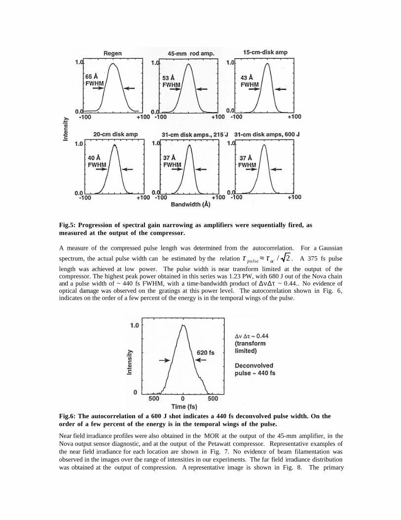
Fig.5: Progression of spectral gain narrowing as amplifiers were sequentially fired, asmeasured at the output of the compressor.
A measure of the compressed pulse length was determined from the autocorrelation. For a Gaussian
spectrum, the actual pulse width can be estimated by the relation τ τpulse ac≈ / 2 . A 375 fs pulse
length was achieved at low power. The pulse width is near transform limited at the output of thecompressor. The highest peak power obtained in this series was 1.23 PW, with 680 J out of the Nova chainand a pulse width of ~ 440 fs FWHM, with a time-bandwidth product of ∆ν∆τ ~ 0.44.. No evidence ofoptical damage was observed on the gratings at this power level. The autocorrelation shown in Fig. 6,indicates on the order of a few percent of the energy is in the temporal wings of the pulse.
Fig.6: The autocorrelation of a 600 J shot indicates a 440 fs deconvolved pulse width. On theorder of a few percent of the energy is in the temporal wings of the pulse.
Near field irradiance profiles were also obtained in the MOR at the output of the 45-mm amplifier, in theNova output sensor diagnostic, and at the output of the Petawatt compressor. Representative examples ofthe near field irradiance for each location are shown in Fig. 7. No evidence of beam filamentation wasobserved in the images over the range of intensities in our experiments. The far field irradiance distributionwas obtained at the output of compression. A representative image is shown in Fig. 8. The primary
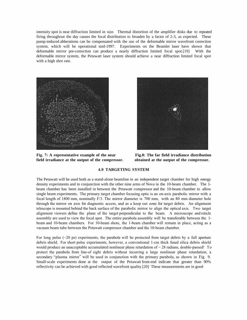
intensity spot is near diffraction limited in size. Thermal distortion of the amplifier disks due to repeatedfiring throughout the day causes the focal distribution to broaden by a factor of 2-3, as expected. Thesepump-induced abberations can be compensated with the use of the deformable mirror wavefront correctionsystem, which will be operational mid-1997. Experiments on the Beamlet laser have shown thatdeformable mirror pre-correction can produce a nearly diffraction limited focal spot.[19] With thedeformable mirror system, the Petawatt laser system should achieve a near diffraction limited focal spotwith a high shot rate.
Fig. 7: A representative example of the near Fig.8: The far field irradiance distributionfield irradiance at the output of the compressor. obtained at the output of the compressor.
4.0 TARGETING SYSTEM
The Petawatt will be used both as a stand-alone beamline in an independent target chamber for high energydensity experiments and in conjunction with the other nine arms of Nova in the 10-beam chamber. The 1-beam chamber has been installed in between the Petawatt compressor and the 10-beam chamber to allowsingle beam experiments. The primary target chamber focusing optic is an on-axis parabolic mirror with afocal length of 1800 mm, nominally F/3. The mirror diameter is 700 mm, with an 80 mm diameter holethrough the mirror on axis for diagnostic access, and as a keep out zone for target debris. An alignmenttelescope is mounted behind the back surface of the parabolic mirror to align the optical axis. Two targetalignment viewers define the plane of the target perpendicular to the beam. A microscope and reticleassembly are used to view the focal spot. The entire parabola assembly will be transferable between the 1-beam and 10-beam chambers. For 10-beam shots, the 1-beam chamber will remain in place, acting as avacuum beam tube between the Petawatt compressor chamber and the 10-beam chamber.
For long pulse (~20 ps) experiments, the parabola will be protected from target debris by a full aperturedebris shield. For short pulse experiments, however, a conventional 1-cm thick fused silica debris shieldwould produce an unacceptable accumulated nonlinear phase retardation of ~ 28 radians, double-passed! Toprotect the parabola from line-of sight debris without incurring a large nonlinear phase retardation, asecondary “plasma mirror” will be used in conjunction with the primary parabola, as shown in Fig. 9.Small-scale experiments done at the output of the Petawatt front-end indicate that greater than 90%reflectivity can be achieved with good reflected wavefront quality.[20] These measurements are in good

Fig 9: (a) A conventional debris shield cannot be used in the Petawatt targeting system for shortpulses. The accumulated nonlinear phase retardation for double-pass through a 1-cm thickfused silica debris shield would produce 28 radians of B. (b) Debris shields can be eliminatedby focusing with a plasma mirror.
Fig. 10: Small-scale experiments done at the output of the Petawatt front-end indicate thatgreater than 90% reflectivity can be achieved with good reflected wavefront quality.Measurements are in good agreement with the theoretical calculations.
agreement with the theoretical calculations shown in Fig 10. For irradiances > 1014 W/cm2 , short pulseradiation creates a critical density plasma on the surface of dielectric materials. For incident pulses < 500fs, the plasma has insufficient time to undergo hydrodynamic expansion, producing a density scale lengthless than the incident wavelength. The resulting reflected wavefront is comparable in quality to thatreflected from a conventional high precision optic, as seen in Fig 11. The plasma mirror substrate can be

either flat or curved to produce a variable F number focal geometry. This substrate also acts as a singleshot debris shield for line-of-sight target debris. Targets will also be specially shaped to help deflect debrisaway from surrounding optics and diagnostics. An additional benefit of the plasma mirror is that thetemporal pre-pulse on the beam is used in forming the plasma mirror, producing a high contrast ratio (107)pulse.
Fig11: For femtosecond pulses, the resulting reflected wavefront from (a) a plasma mirror iscomparable in quality to that reflected from (b) a conventional high precision optic.
5.0 SUMMARY
The overall performance of the Petawatt Laser to date has exceeded expectation. We have demonstrated theproduction of over a petawatt of peak power in the Nova/Petawatt Laser Facility, generating > 600 J in <500 fs. Currently, this system is limited to 600 J pulses in a 46.3-cm beam. Expansion of the beam to 58cm, with the installation of 94-cm gratings, will enable 1 kJ operation. Target experiments with petawattpulses will be possible either integrated with Nova in the 10 beam target chamber or as a stand alonesystem in an independent, dedicated chamber. Focusing the beam onto a target will be accomplished usingan on-axis parabolic mirror either alone, or in conjunction with a plasma mirror, enabling the production ofultrahigh contrast pulses and an easily variable effective focal length. At the shortest pulse lengths, thislaser should surpass 10
21 W/cm
2 when focused in May.
6.0 ACKNOWLEDGEMENTS
The authors would like to thank the members of the Nova Engineering and Operations staff for theirassistance in the design and activation of the Petawatt Laser System, and performing these experiments.This work was performed under the auspices of the U.S. Department of Energy by the Lawrence LivermoreNational Laboratory under Contract No. W-7405-ENG-48.
7.0 REFERENCES
[1] M. Tabak, J. Hammer, M. E. Glinsky, W. L. Kruer, S. C. Wilks, J. Woodworth, E. M.Campbell,
M. D. Perry, and R. J. Mason, “Ignition and high gain with ultra-powerful lasers,” Phys.

Plasmas, vol. 1, pp. 1626-1634, 1994.[2] J. Lindl, “Development of the indirect-drive approach to inertial confinement fusion and the
target physics basis for ignition and gain,” Physics of Plasmas , vol. 2, pp. 3933-4024, 1995.[3] C. E. Cook, “Pulse compression- key to more efficient radar transmission,” Proc. IRE, vol. 48,
pp. 310-316, 1960.[4] R. A. Fisher and W. K. Bischel, “Pulse compression for more efficient operation of solid-state
laser amplifier chains II,” IEEE J. Quantum Electron., vol. QE-11, pp. 46-52, 1975.[5] D. Strickland and G. Mourou, “Compression of amplified chirped optical pulses,” Opt. Comm.,
vol. 56, pp. 219-221, 1985.[6] C. Sauteret, D. Husson, G. Thiell, S. Seznac, et. al., “Generation of 20-TW pulses of picosecond
duration using chirped-pulse amplification in a Nd:glass power chain,” Opt. Lett., vol. 16, pp.238, 1991.
[7] C. Rouyer, E. Mazataud, I. Allais, A. Pierre, S. Seznac, C. Sauteret, and G. Mourou,“Generation of 50-TW femtosecond pulses in a Ti:sapphire/Nd:glass chain,” Opt. Lett., vol. 18,pp. 214-216, 1993.
[8] C. N. Danson, L. Barzanti, Z. Chang, A. Damerell, et. al. , “High contrast multi-terawatt pulsegeneration using chirped pulse amplification on the Vulcan Laser Facility,” Opt. Comm., vol.103, pp. 392-397, 1993.
[9] K. Yamakawa, H. Shiraga, and Y. Kato, Opt. Lett., vol. 16, pp. 1593, 1991.[10] M. D. Perry, F. G. Patterson, and J. Weston, “Spectral shaping in chirped-pulse amplification,”
Opt. Lett., vol. 15, pp. 381-383, 1990.[11] B. C. Stuart, M. D. Perry, J. Miller, G. Tietbohl, S. Herman, J. A. Britten, C. Brown, D.
Pennington, and V. Yanovsky, “125-TW Ti:sapphire/Nd:glass laser system,” Opt. Lett., 1997.[12] R. Boyd, J. Britten, D. Decker, B. W. Shore, B. C. Stuart, M. D. Perry, and L. Li, “High-
efficiency metallic diffraction gratings for laser applications,” Appl. Opt., vol. 34, pp. 1697-1706, 1995.
[13] B. C. Stuart, S. Herman, and M. D. Perry, “Chirped-pulse amplification in Ti:sapphire beyond1 µm,” IEEE J. Quantum Electron., vol. 31, pp. 528-538, 1995.
[14] B. C. Stuart, M. D. Feit, A. M. Rubenchik, B. W. Shore, and M. D. Perry, “Laser induceddamage in dielectrics with nanosecond to subpicosecond pulses,” Phys. Rev. Lett., vol. 74, pp.2248-2251, 1995.
[15] B. C. Stuart, M. D. Feit, A. M. Rubenchik, B. W. Shore, and M. D. Perry, “Nanosecond tofemtosecond laser induced breakdown in dielectrics,” Phys. Rev. B, vol. 53, pp. 1749-1761,1996.
[16] Y. R. Shen, The Principles of Nonlinear Optics. New York: Wiley, 1984.[17] W. Koechner, Solid-State Laser Engineering , 3rd ed. New York: Springer-Verlag, 1990.[18] M. D. Perry, T. Ditmire, and B. C. Stuart, “Self-phase modulation in chirped-pulse
amplification,” Opt. Lett., vol. 19, pp. 2149-2151, 1994.[19] B. M. V. Wonterghem, E. S. Bliss, J. A. Caird, R. G. Hartley, M. W. Kartz, J. T. Salmon, andP.
J. Wegner, “Experimental measurements of deformable mirror effects on focal spot irradiancedistributions,” presented at Solid-State Lasers for Application to Inertial Confinement Fusion,Paris, France, 1996.
[20] M. D. Perry, V. Yanovsky, M. Feit, and A. Rubenchik, “Plasma mirrors,” Phys. Plasmas,submitted, 1997.

Technical Inform
ation Departm
ent • Lawrence Liverm
ore National Laboratory
University of C
alifornia • Livermore, C
alifornia 94551