the port talbot steelworks (power generation enhancement ...... · the port talbot steelworks...
TRANSCRIPT

Planning Act 2008 The Infrastructure Planning (Applications: Prescribed Forms and Procedure) Regulations 2009
The Port Talbot Steelworks (Power Generation Enhancement) Order
MAH1.01 - High Level Assessment of Major Accident Hazards
PINS Reference EN010062
Document No. MAH1.01
Author Pinsent Masons
Revision Date Description
0 April 2015 Submission Version

The Port Talbot Steelworks (Power Generation Enhancement) Order High Level Assessment of Major Accident Hazards MAH1.01
April 2015 2
Contents 1. Introduction .............................................................................................. 3
2. Executive Summary ................................................................................. 5
3. Review of Major Hazards ......................................................................... 6
4. Major Loss of Containment of Fuel Gas ................................................ 7
5. Conclusions ........................................................................................... 11
Appendices:
Appendix 1 - Process Risk Assessment Process
Appendix 2 - Calculations
Appendix 3 - DNV-GL ‘Corus Technical Note’
Appendix 4 - Port Talbot Steelworks Safety Report 2013

The Port Talbot Steelworks (Power Generation Enhancement) Order High Level Assessment of Major Accident Hazards MAH1.01
April 2015 3
1. Introduction
1.1 This report has been written in support of an application by Tata Steel UK Limited ("Tata") under the Planning Act 2008 for a development consent order ("DCO") to construct, operate and maintain a process gas-fired power generating station ("the Proposed Development") within the Port Talbot Steelworks at Port Talbot, South Wales ("the Application").
1.2 The report contains a high-level assessment of the extent and severity of known major hazards at the Proposed Development with the potential to impact on the existing steelworks installation and the local population.
1.3 As a result of the presence of 'hazardous substances'1 at installations within the Port Talbot steelworks site, the site is a ‘Control of Major Accident Hazards (COMAH) Tier 1’ site. Tata is therefore obliged to hold and maintain a 'safety report' for the site under the terms of the Control of Major Accident Hazards Regulations 1999 ("the COMAH Regulations").
1.4 Although the Proposed Development would not itself be a COMAH site for the purposes of the COMAH Regulations, it would be situated within the formal 'consultation zone' of the steelworks which is a regulated 'establishment'2. When new facts arise or modifications take place within a regulated establishment, the safety report for that site may need to be reviewed under the terms of regulation 8 of the COMAH Regulations.
1.5 As no additional qualifying inventories of COMAH substances will be present at the Proposed Development, Tata currently considers that the current ‘2013 COMAH Safety Report’ for the steelworks site will not need updating. Instead, the presence of the Proposed Development will be reflected in the ‘2018 Port Talbot COMAH Safety Report’. Final decisions in relation to the COMAH Safety Report will be taken once more information becomes available on the design of the Proposed Development. This approach has been verbally agreed with Tata's Principal HSE Inspector, Mr Alan Strawbridge.
1.6 Tata has adopted a six stage risk assessment process to review health and safety risks within the consultation zone of the Port Talbot Steelworks COMAH site. The stages in this process are set out in detail in the ‘2013 Port Talbot Safety Report’, an extract of which outlining these phases is enclosed at Appendix 1 to this report.
1 As defined in regulation 2 of the Control of Major Accident Hazards Regulations 1999 2 As defined in regulation 2 of the COMAH Regulations.

The Port Talbot Steelworks (Power Generation Enhancement) Order High Level Assessment of Major Accident Hazards MAH1.01
April 2015 4
1.7 Tata's Process Safety Department (part of the Health, Safety and Environmental Department) has carried out a high-level, initial assessment of the potential for increased risk to health and safety at the Port Talbot Steelworks as a result of the Proposed Development. This initial review forms part of the existing six-stage framework. The Proposed Development has passed the first (HS1) stage of this package of risk assessments and the findings of that initial assessment are set out in this report, the "HS1 Stage 'High Level' Risk Assessment".
1.8 The Proposed Development will in due course be assessed at the HS2 stage, when more detailed information is available about the detailed design. The HS2 stage will result in a more granular and detailed risk assessment. Both HS1 and HS2 stages are in the ‘Inherently Safe Design’ phase where actions and recommendations focus on eliminating, reducing, replacing or simplifying the threats and sources of hazards.
1.9 As the design progresses, a more detailed set of Process Hazard Review and Risk Assessments (HS3) will be carried out to ensure that the risks are controlled to ‘As Low As Reasonably Practicable’ (ALARP). Where ‘Major Accident Hazards’ are identified, ‘Layer of Protection Analysis’ (LOPA) studies will be carried out to ensure that the causative mechanisms are credible, that the safeguards claimed are documented, any improvements recommended from the risk assessments captured and an ALARP demonstration made.
1.10 As stated above, it has been agreed with Tata's Principal HSE Inspector that the current ‘2013 COMAH Safety Report’ will not need updating at present. Tata will, however, continue to complete the six-stage assessment process in respect of the Proposed Development and will keep the HSE informed of any change in assumptions, risks or proposed approach.

The Port Talbot Steelworks (Power Generation Enhancement) Order High Level Assessment of Major Accident Hazards MAH1.01
April 2015 5
2. Executive Summary
2.1 This assessment identifies that the only possible, known major hazard from the Proposed Development is the potential for major loss of containment fuel gas from inside the power generation plant building due to a guillotine of gas pipework and a subsequent escape of fuel gas from the power generation plant building. Such an escape would have the potential to impact both the wider Port Talbot Steelworks site and the local community, most especially those in Tiabach.
2.2 This assessment concludes that such an escape is a barely credible threat and, in the unlikely event that it did occur, a number of controls would be in place to limit the duration of any such release and therefore the risk to the public. The assessment further finds that, even if the control measures failed to prevent or mitigate a catastrophic release of fuel gas, the Proposed Development poses no additional ‘Major Accident Hazard’ to on-site or off-site populations. In other words, the presence of the Proposed Development would not increase the risk from the rest of the steelworks site.
2.3 The information contained in this report is intended to demonstrate the suitability of the site for the Proposed Development and show that Tata has adequately considered the impact of known hazards from the Proposed Development to the public. Potential risks will continue to be considered as the design of the Proposed Development is progressed to ensure that any such risks are adequately managed and controlled through the design, site safety procedures and through Tata's on-going obligations under the COMAH Regulations.

The Port Talbot Steelworks (Power Generation Enhancement) Order High Level Assessment of Major Accident Hazards MAH1.01
April 2015 6
3. Review of Major Hazards
3.1 An assessment of the existing risks on the Port Talbot is given in the Port Talbot 2013 COMAH Safety Report', which is appended to this report.
3.2 The Proposed Development comprises only a very small addition to the existing inventory of hazardous substances on the Port Talbot Site. The only hazardous substance affected by the Proposed Development is the blast furnace gas (BFG), the volume of which will increase by only around 100m³ (of a current total volume of around 100,000m³). In addition, although the existing pipe work carrying the BFG will be extended slightly to accommodate the Proposed Development, the location of the hazardous substances within the site is not considered to change in any significant way, and in particular the BFG will not be brought significantly closer to the boundary of the site within these new pipes. The risk of known major hazards across the Port Talbot COMAH site is therefore not considered to increase to the extent that the current safety report needs to be reviewed. This conclusion has been discussed with Tata's HSE Principal Inspector and will be kept under continual review as the assessment progresses through Tata's 6 stage process.
3.3 Tata has concluded that the only new or different major hazard that could potentially arise from the Proposed Development is the possibility for major loss of containment of fuel gas from inside the power generation plant building of the Proposed Development and a subsequent escape of gas from that building. The potential consequences of such an incident are described in section 4 below.

The Port Talbot Steelworks (Power Generation Enhancement) Order High Level Assessment of Major Accident Hazards MAH1.01
April 2015 7
4. Major Loss of Containment of Fuel Gas
4.1 Major loss of containment of fuel gases (one of which is highly toxic) from inside the proposed power generation plant building and a subsequent escape of gas from that building would have the potential to impact both the wider Port Talbot Steelworks site and the local community, most especially those in Tiabach.
4.2 In order to capture the likelihood and potential severity of such a major loss of containment of fuel gas from the Proposed Development, Tata has reviewed early plans for the design of the Proposed Development and undertaken dispersion modelling. The results of this modelling are set out in Appendix 2 of this report.
4.3 Blast-furnace gas ("BFG") is the primary fuel gas for the Proposed Development. BFG has a high ignition temperature and low calorific value and therefore does not ignite easily. BFG also contains some toxic gases which are harmful to human health, including carbon monoxide. Natural gas, which the proposed development may use as back up fuel, would ignite more easily but is not as toxic as BFG.
4.4 Although the likelihood of either fuel gas igniting (in an uncontrolled way) is very low, should it occur, the Proposed Development will not impact on the risk profile of the wider Port Talbot. This is because:
4.4.1 the nature of the hot fired plant means there would be many sources of ignition local to any release, such that fires or delayed ignitions are likely to occur soon after release and inside the power generation building only; and
4.4.2 as the Proposed Development is some considerable distance from all of the main installations and buildings located on the wider Port Talbot site, such an ignition with the power generation building would not increase risks to other parts of the site.
4.5 The nature of natural gas means that, were it to escape, it is likely the natural gas would ignite quickly and close to the point of release. In contrast, BFG would not ignite easily upon its release and is therefore more likely to escape from the boundary of the Proposed Development. This means that the ‘Major Accident’ scenarios impacting beyond the boundary of the Proposed Development are limited to a toxic gas release of BFG from inside the power generation plant building of the Proposed Development. This would only occur due to a guillotine or damage to one or both of the 72” diameter BFG fuel gas pipelines.
4.6 If the fuel pipes carrying BFG were to be damaged outside the buildings housing the Proposed Development, the leaked gas would be contained within the existing ducts carrying the piping and would travel at ground level. The risk posed by damage to external pipes carrying BFG is something which is already covered by the existing Safety Report and, as the length of additional pipework and ducting

The Port Talbot Steelworks (Power Generation Enhancement) Order High Level Assessment of Major Accident Hazards MAH1.01
April 2015 8
required for the Proposed Development is minimal (and does not take the BFG piping closer to the site boundary), this is a risk which is not increased by the introduction of the Proposed Development.
4.7 The possibility of fuel pipes carrying BFG being damaged inside buildings of the same size and location as those which will be required to house the Proposed Development is however not a scenario which is directly covered in the existing Safety Report. Tata has therefore considered this in more detail (including undertaking dispersion modelling) as it represents the only Major Accident scenario that could impact beyond the boundary of the Proposed Development.
4.8 It should be noted that it is highly unlikely that fuel gas pipes would be damaged because there are no credible causative mechanisms. Even if the pipe carrying the fuel gases was somehow to be guillotined or damaged, it is considered even more unlikely that such an escape of gas would go unnoticed for a significant period of time because there will be a number of controls in place to limit the duration of such a release. Such controls will include toxic and flammable gas detection systems and alarms both inside and outside the perimeter of the building.
4.9 These controls will be built into the final design of the Proposed Development and will be incorporated into the operation of the Proposed Development via the successful contractor under Tata Steel Design requirements.
Dispersion Modelling – Methodology
4.10 In the very unlikely event that fuel gas pipes were to be damaged inside the buildings of the Proposed Development, the effect of such a release on local populations would depend on the duration of the release, how it would be contained and the extent to which the gas disperses. To measure the possible effects of such an event, Tata has undertaken dispersion modelling. The results of this modelling are presented in Appendix 2.
4.11 Whilst the chemistry of the fuel gases is well documented, data about the final design which is needed to enable precision modelling is not available at this stage. Assumptions have therefore been made regarding the location and size of building vents to allow the dispersion modelling to be carried out.
4.12 The modelling has assumed that the building is a pressure vessel that has been pressurised to 50mbg by a massive Loss of Containment (LoC) of un-ignited BFG which is vented to atmosphere from vertically orientated roof vents at 35m elevation. These assumptions are based on the size of volume relief vents elsewhere on the steelworks site and are considered reasonable based on the information presently available. Should these assumptions change as the design progresses, Tata will revisit this modelling as part of the continuing six-stage assessment process it is committed to in order to comply with its COMAH obligations for the steelworks site.

The Port Talbot Steelworks (Power Generation Enhancement) Order High Level Assessment of Major Accident Hazards MAH1.01
April 2015 9
4.13 Tata has completed this initial modelling internally using ‘Det Norke Veritas (DNV-GL) PHAST 7.0’ modelling software and has also used previous similar modelling from both DNV-GL and ‘Hazard Research & Risk Consultants Ltd (HazRes)’ to lend validation to the models.
4.14 Further modelling will be carried out as the design is finalised, to feed into more detailed assessments of the risk of the Proposed Development as part of the six-stage process described above.
4.15 Although Tata Steel have a DNV-GL PHAST software licence and have competence in its use for dispersion and explosion modelling, it is recognised that, at a later stage, it will be appropriate for the models to either be conducted or validated by an independent and competent third party. Such a requirement and the outcome of a further analysis will be discussed with the Health and Safety Executive when appropriate.
Dispersion Modelling – Estimate of Severity
4.16 Although the models are based on the best data available (including assumptions frequently made and the historical evidence), it must be emphasised that the likelihood of these events occurring is considered negligible, not only in scale but in causative mechanism.
4.17 Nevertheless, should such an event take place, the modelling demonstrates that the most significant potential consequence would be fatalities associated with the toxicity of the BFG, as BFG contains a large proportion of carbon monoxide.
4.18 The dispersion modelling shows that any highly toxic gas plumes emanating from the power generation building of the Proposed Development would rise higher than the 35 metre roof line of the buildings on site and would rise to in excess of 50 metres above ground level as they crossed the perimeter road. By the time any such plumes were to reach neighbouring properties, the plumes would be over 100 metres high and therefore highly unlikely to cause a risk to health.
4.19 If the wind was blowing towards the wider Port Talbot site there is the potential for any escaped plumes (especially plumes of lower concentrations) to reach any person working at the higher heights on the blast furnaces (such work only ever being intermittent and temporary). This event is however far less likely to occur than the impact of a loss of containment of BFG from one blast furnace area to another, which is a risk already discussed in that installation’s risk assessments and which would invoke an established plant evacuation procedure.
4.20 As the design of the Proposed Development is finalised, measures in alignment with best practice and applicable guidance and standards to prevent, control and mitigate these scenarios will be implemented.
4.21 These best practice measures will be determined as the design progresses, more accurate design data becomes available and modelling is carried out. The

The Port Talbot Steelworks (Power Generation Enhancement) Order High Level Assessment of Major Accident Hazards MAH1.01
April 2015 10
measures will be secured via further risk assessments as the design progresses in accordance with Tata Steel Safety Management System and auditable implementation at the ‘HS4’ stage of the Tata Steel six stage project Risk Assessment process.

The Port Talbot Steelworks (Power Generation Enhancement) Order High Level Assessment of Major Accident Hazards MAH1.01
April 2015 11
5. Conclusions
5.1 The Proposed Development at the Port Talbot steelworks site would pose no additional ‘Major Accident Hazard’ to on-site or off-site populations even if the control measures fail to prevent or mitigate a catastrophic release of BFG due to guillotine of the toxic 72” BFG pipework within the power generation plant within the Proposed Development.

The Port Talbot Steelworks (Power Generation Enhancement) Order
MAH1.01 - High Level Assessment of Major Accident Hazards
Appendices

The Port Talbot Steelworks (Power Generation Enhancement) Order
MAH1.01 - High Level Assessment of Major Accident Hazards
Appendix 1: Process Risk Assessment Process

Reference Page Revision Date Prepared by
PT Power Plant Development 1 Issue 1 18/08/2011 Malcolm Warren
Appendix 1: Six Stage Project Risk Assessment Process

Reference Page Revision Date Prepared by
PT Power Plant Development 2 Issue 1 18/08/2011 Malcolm Warren
PROJECT OVERVIEW
HAZARD IDENTIFICATION
PROPOSED DESIGN HAZOP
FINAL DESIGN (including FDS) fixed for Construction
MOC RECORD
Produce brief overview describing project
ALL CHANGES RECORDED:Risk assessments carried out and
recorded for changes.
PROGRESS PROJECT TASKLIST:attach into MOC record
TENDER (Based On User
Requirement Specification)
OUTCOMESWHY
Introduction to Project
Determine an outline of proposals together with a
cost indication
Scope Definition Studies and re-design to remove
hazards
Identify high level/ low cost impacting changes
required to satisfy safety, environmental and asset
issues
INHERENT SAFETY STAGE
‘STRATEGIC’ HAZARDS IDENTIFIED:TEAM Event
Carried Out On Scope Definition Studies, Planning Permission
Manning, MaintainabilityInfrastructure, Service/utilities
User Requirement Specification developed
Review design proposals from selected contractors
FUNCTIONAL SAFETY STAGE
‘PROCESS’ HAZARDS IDENTIFIED:Team Event
Inputs include any existing PHR/LOPA/HAZOP’s
Layer Of Protection Analysis (LOPA) and CBA for ALARP Demonstration
Manage the design change
MOC TASKLIST
PROGRESS MOC RECORD THROUGH TO COMPLETION
Manage/monitor project tasks
Manage/monitor project phases
ApprovalAuthorisation
Installation & CommissioningCompletion
Rev.6 (10/1/13)
Process Safety Flowchart
SAFEGUARD REGISTER
ALARP Demonstration and determination of
residual risk Carry out SIL/LOPA studies for any
SISs
DESIGN COMPLETION: risks controlled to ALARP
ALARP demonstration cases in progress
Confirm Final Design
MOCDefines ownership and authorisation of Project
Key Stages
UMBRELLA DOCUMENT:Authoriser, Approver
Captures brief project description
Re-Design to remove hazards or include
additional ‘Safeguards’
CONTRACTOR SELECTED
Engineering progressed to an Accurate Design Representation
and Functional Design Speciification suitable for HAZOP etc.
All Safeguards defined to Contractor
RISKS ASSESSED;HAZAN, QRA
Safety Functions Allocated to Safeguards and CBA carried out.
SAFEGUARD DEFINITION DOCUMENT:Procedures
Safety Instrumented Systems (SIS),Non Return Valves (NRV),
Pressure Relief Valves (PRV),
Hazards require risk reduction by Safeguards
or re-design
Define Hazards and Safeguards

The Port Talbot Steelworks (Power Generation Enhancement) Order
High Level Assessment of Major Accident Hazards
Appendix 2: Calculations

The Port Talbot Steelworks (Power Generation Enhancement) Order High Level Assessment of Major Accident Hazards MAH1.01
1. Calculated Extent PHAST
Several projects which included works to the gas infrastructure have been carried out by Tata Steel at Port Talbot Steelworks in recent years (for example BOS Gas Recovery, BF4 Re-Build, New Perimeter Road and the New COG Holder Projects) and, as a result, a great deal of independent dispersion modelling has been carried out for major Losses of Containment.
The BOS Gas recovery project in particular engaged DNV-GL to carry out modelling of release of both BOS Gas and BFG from the volume relief vents in the new BOS Gas Holder. To capitalise further on this existing work the BFG release model was used to calibrate and lend validation to the internal model of BFG LoC from roof vents in the new power plant, this calibration can be reviewed by comparing the ‘5D weather conditions’ 12800ppm CO plume shown in Graph 2 with Graph 1 from Figure 111.16 of the DNV-GL ‘Corus Technical Note’, see Appendix 3 which shows a reasonable correlation.
Graph 1 from 111.16 of the DNV-GL ‘Corus Technical Note’ NB: (yellow is 55% CarboxyHemaglobin COHb which broadly corresponds to 12800 ppm CO)

The Port Talbot Steelworks (Power Generation Enhancement) Order High Level Assessment of Major Accident Hazards MAH1.01
Graph 2 Tata Steel ‘Model Calibration’
Using the model configuration and settings used to generate Graph 2 the release point and area was changed to 35 metres elevation, the Power Plant roof level, and run for 1 Metre diameter and 2 Metre diameter (total area equivalent of 5 x 1 m dia) vertically orientated roof vents.
Graph 3 and Graph 4 show that the plume does not touch the ground in both ‘2F weather conditions’ and ‘5D weather conditions’ in both cases.
Graph 3: 1 metre diameter roof vent

The Port Talbot Steelworks (Power Generation Enhancement) Order High Level Assessment of Major Accident Hazards MAH1.01
Graph 4: 5 x 1 metre diameter roof vents

The Port Talbot Steelworks (Power Generation Enhancement) Order
High Level Assessment of Major Accident Hazards
Appendix 3: DNV-GL ‘Corus Technical Note’

DET NORSKE VERITAS
PHAST Modelling of
BOS and Blast Furnace Gas Releases
Corus Strip Products UK
Report no/DNV ref no: 22635811 Rev 3, December 2008


DET NORSKE VERITAS
PHAST Modelling of BOS Gas Releases
Corus Strip Products UK
MANAGING RISK
Date : <01/12/2088>
Table of Content Page
1 INTRODUCTION ............................................................................................................. 1
2 APPROACH....................................................................................................................... 1
2.1 Release Scenarios.......................................................................................................... 1
2.2 Hazard Levels................................................................................................................ 6
2.3 Assumptions.................................................................................................................. 6
3 RESULTS ........................................................................................................................... 7
3.1 Release Modelling......................................................................................................... 7
3.2 Consequences................................................................................................................ 7
4 DISCUSSION................................................................................................................... 17
APPENDIX I: DERIVATION OF CO CONCENTRATIONS OF INTE REST.............. 19
APPENDIX II: WORST-CASE DISPERSION TO CO CONCENTRAT IONS OF INTEREST ....................................................................................................................... 20
II.1 Gas Holder .................................................................................................................. 21
II.2 Distribution System..................................................................................................... 29
II.3 Collection System ....................................................................................................... 33
APPENDIX III: WORST-CASE DISPERSION TO CO CONCENTRA TIONS OF INTEREST FOR THE NEW MODELLED CASES ................................................... 41
III.1 Gas Holder ................................................................................................................. 42
III.2 Distribution system.................................................................................................... 58

DET NORSKE VERITAS
PHAST Modelling of BOS Gas Releases
Corus Strip Products UK
MANAGING RISK
Date : <01/12/2088>

DET NORSKE VERITAS
PHAST Modelling of BOS Gas Releases
Corus Strip Products UK
MANAGING RISK
Date : <01/12/2088> Page 1
1 INTRODUCTION Corus Strip Products plan to build a gasholder for BOS Gas and associated piping at their Port Talbot works in South Wales. BOS gas contains 50% to 60% carbon monoxide depending on temperature, besides hydrogen, nitrogen, carbon dioxide and water vapour. It is therefore both toxic and flammable.
Corus have identified potential “worst case” scenarios for releases of BOS gas from the gas holder, associated piping (which is of large diameter) and vents. They have contracted DNV to model the toxic and flammable consequences of these releases using DNV’s commercial software PHAST and to present these in terms of distances to specified hazard levels. Corus hold licences for PHAST and are therefore familiar with the software.
Section 2 of this Technical Note summarises the approach DNV have adopted in discussion with Corus, including the scenarios specified, hazard levels modelled and assumptions made.
Section 3 first of all sets out the results obtained from the modelling of release rate, which determines the duration of most of the release scenarios and in turn the toxic concentrations of concern. This section then presents in tabular form the worst case hazard distances for each scenario and effect level.
The results are briefly discussed in Section 4.
2 APPROACH This section summarises the release scenarios and hazard levels modelled, as well as summarising any assumptions made.
2.1 Release Scenarios
The plant items that were considered for the purposes of this analysis are:
• Gas Holder, which includes the Gas Holder, Inlet Stub, Outlet stub and a series of vents.
• Distribution System, which mainly includes piping.
• Collection System, which includes piping and the Cooler Outlet.
Corus have indicated that a series of release scenarios from each of the above plant items are to be considered as potential releases. These are summarised in Table 2.1.
Only two (2) BOS gas compositions were modelled, at temperatures of 40° and 70°C, saturated, and at pressures slightly over atmospheric.
In addition, some new cases have been requested to be modelled. These are summarized in Table 2.2. Three (3) BOS gas compositions were modelled, at temperatures of 20°C, 40°C and 70°C, saturated, and at pressures slightly over atmospheric. In addition, release of Blast Furnace Gas (BFG) from the Gas Holder vents has been taken into account.

DET NORSKE VERITAS
PHAST Modelling of BOS Gas Releases
Corus Strip Products UK
MANAGING RISK
Date : <01/12/2088> Page 2
Table 2.1: Release Scenarios Considered
Plant Item Component Vessel type / Pipe and diameter
Failure mode Potential
release Nm3 Substance
Temperature (°C)
Pressure (bara)
Release height (m)
75000 1
63000 5
51000 10 Gas holder Tank
Hole 500 mm dia
39000
BOS gas 40 1.02
15
Pipe 2300 mm dia Hole 500 mm
dia 75000 BOS gas 70 1.02 2
Pipe 2300 mm dia Guillotine fracture
75000 BOS gas 70 1.02 2
Pipe 2300 mm dia Hole 500 mm
dia 75000 BOS gas 40 1.02 2
Inlet stub
Pipe 2300 mm dia Guillotine fracture
75000 BOS gas 40 1.02 2
Pipe 1370 mm dia Hole 500 mm
dia 75000 BOS gas 70 1.02 2
Pipe 1370 mm dia Guillotine fracture
75000 BOS gas 70 1.02 1
Pipe 1370 mm dia Hole 500 mm
dia 75000 BOS gas 40 1.02 2
Outlet stub
Pipe 1370 mm dia Guillotine fracture
75000 BOS gas 40 1.02 1
Pipe 650 mm dia Open end Continuous BOS gas 40 1.02 52
Vent
Pipe 650 mm dia Open end Continuous BOS gas 70 1.02 52
Gas holder
Vents Pipe 650 mm dia × 12 Open end Continuous BOS gas 40 1.02 52

DET NORSKE VERITAS
PHAST Modelling of BOS Gas Releases
Corus Strip Products UK
MANAGING RISK
Date : <01/12/2088> Page 3
Plant Item Component Vessel type / Pipe and diameter
Failure mode Potential
release Nm3 Substance
Temperature (°C)
Pressure (bara)
Release height (m)
Pipe 650 mm dia × 12 Open end Continuous BOS gas 70 1.02 52
Pipe 1370 mm dia Hole 500 mm
dia Continuous BOS gas 40 1.15 2
Pipe 1370 mm dia Guillotine fracture
Continuous BOS gas 40 1.15 2
Pipe 1370 mm dia Hole 500 mm
dia Continuous BOS gas 70 1.15 2
Distribution System Pipe
Pipe 1370 mm dia Guillotine fracture
Continuous BOS gas 70 1.15 2
2 Pipe 2300 mm dia
Hole 500 mm dia
75000 BOS gas 70 1.02 8
2 Pipe 2300 mm dia
Guillotine fracture
75000 BOS gas 70 1.02 8
Pipe 2300 mm dia Hole 500 mm
dia 75000 BOS gas 40 1.02 8
Pipe
Pipe 2300 mm dia Guillotine fracture
75000 BOS gas 40 1.02 8
Pipe 2300 mm dia Hole 500 mm
dia 75000 BOS gas 70 1.02 18
Pipe 2300 mm dia Guillotine fracture
75000 BOS gas 70 1.02 18
Pipe 2300 mm dia Hole 500 mm
dia 75000 BOS gas 40 1.02 18
Collection system
Cooler outlet
Pipe 2300 mm dia Guillotine fracture
75000 BOS gas 40 1.02 18

DET NORSKE VERITAS
PHAST Modelling of BOS Gas Releases
Corus Strip Products UK
MANAGING RISK
Date : <01/12/2088> Page 4
Table 2.2: Additional Scenarios Considered
Plant Item Component Vessel type and
diameter Failure mode
Potential release Nm3
Substance Temperature
(°C) Pressure (bara)
Release height
1
5
10
Hole 500 mm dia
86000 BOS gas 70 1.02
15
1
5
10
Hole 500 mm dia
86000 BOS gas 40 1.02
15
1
5
10
Gas Holder (shell) Tank
Hole 500 mm dia
86000 BOS gas 20 1.02
15
70 1.02 1
40 1.02 1 Inlet Stub Pipe 2300 mm dia Hole 500 mm
dia 86000 BOS gas
20 1.02 1
70 1.02 2.2
40 1.02 2.2 Outlet stub Pipe 1200 mm dia Hole 500 mm
dia 86000 BOS gas
20 1.02 2.2
Vent Pipe 650 mm dia Open end 30 min Furnace Gas 20 1.05 52
Gas Holder
Vents Pipe 650 mm dia x 12 Open end 30 min Furnace Gas 20 1.05 52

DET NORSKE VERITAS
PHAST Modelling of BOS Gas Releases
Corus Strip Products UK
MANAGING RISK
Date : <01/12/2088> Page 5
Plant Item Component Vessel type and
diameter Failure mode
Potential release Nm3
Substance Temperature
(°C) Pressure (bara)
Release height
8
10 BOS gas 70 1.2
16
8
10 BOS gas 40 1.2
16
8
10
116 tonnes
BOS gas 20 1.2
16
8
10 BOS gas 70 1.2
16
8
10 BOS gas 40 1.2
16
8
10
Distribution system Pipe Pipe 1200 mm dia Hole 500 mm
dia
35 min
BOS gas 20 1.2
16
DET NORSKE VERITAS
PHAST Modelling of BOS Gas Releases
Corus Strip Products UK
MANAGING RISK
Date : <01/12/2088> Page 6
2.2 Hazard Levels
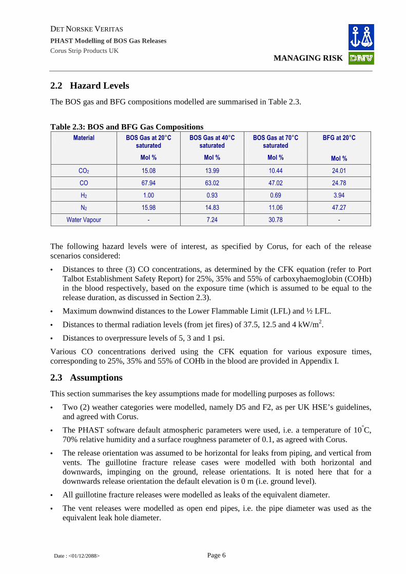
The BOS gas and BFG compositions modelled are summarised in Table 2.3.
Table 2.3: BOS and BFG Gas Compositions Material BOS Gas at 20°C
saturated
Mol %
BOS Gas at 40°C saturated
Mol %
BOS Gas at 70°C saturated
Mol %
BFG at 20°C
Mol %
CO2 15.08 13.99 10.44 24.01
CO 67.94 63.02 47.02 24.78
H2 1.00 0.93 0.69 3.94
N2 15.98 14.83 11.06 47.27
Water Vapour - 7.24 30.78 -
The following hazard levels were of interest, as specified by Corus, for each of the release scenarios considered:
• Distances to three (3) CO concentrations, as determined by the CFK equation (refer to Port Talbot Establishment Safety Report) for 25%, 35% and 55% of carboxyhaemoglobin (COHb) in the blood respectively, based on the exposure time (which is assumed to be equal to the release duration, as discussed in Section 2.3).
• Maximum downwind distances to the Lower Flammable Limit (LFL) and ½ LFL.
• Distances to thermal radiation levels (from jet fires) of 37.5, 12.5 and 4 kW/m2.
• Distances to overpressure levels of 5, 3 and 1 psi.
Various CO concentrations derived using the CFK equation for various exposure times, corresponding to 25%, 35% and 55% of COHb in the blood are provided in Appendix I.
2.3 Assumptions
This section summarises the key assumptions made for modelling purposes as follows:
• Two (2) weather categories were modelled, namely D5 and F2, as per UK HSE’s guidelines, and agreed with Corus.
• The PHAST software default atmospheric parameters were used, i.e. a temperature of 10°C, 70% relative humidity and a surface roughness parameter of 0.1, as agreed with Corus.
• The release orientation was assumed to be horizontal for leaks from piping, and vertical from vents. The guillotine fracture release cases were modelled with both horizontal and downwards, impinging on the ground, release orientations. It is noted here that for a downwards release orientation the default elevation is 0 m (i.e. ground level).
• All guillotine fracture releases were modelled as leaks of the equivalent diameter.
• The vent releases were modelled as open end pipes, i.e. the pipe diameter was used as the equivalent leak hole diameter.

DET NORSKE VERITAS
PHAST Modelling of BOS Gas Releases
Corus Strip Products UK
MANAGING RISK
Date : <01/12/2088> Page 7
• A release duration of 1.5 hours was assumed, as agreed with Corus, for all releases described in Table 2.1 as “Continuous”, using the discharge rate as predicted by the PHAST software.
• For releases with a defined, limited inventory, the discharge rate was assumed to be constant throughout the release duration, which was determined by the available inventory. For the original scenarios (as set out in Table 2.1), the maximum release duration was assumed, as for the “Continuous” release cases, to be 1.5 hours. For the additional Gas Holder cases (Table 2.2), the release duration is calculated as the potential release quantity divided by the discharge rate, with no limit.
• All distances to toxic concentrations and radiation levels of interest are reported at a height of 1.5 m.
• For the toxic effects, the averaging time was assumed equal to the exposure time, i.e. the release duration (see Section 2.2 for CO concentrations of interest).
• The maximum downwind distances to LFL and ½ LFL are reported at the cloud centreline height.
• The explosion modelling was conducted with the PHAST software, using the TNT explosion model (an unconfined vapour cloud explosion model) with the software default values.
3 RESULTS
This section summarises the results for all the release scenarios considered, in terms of the release and consequence modelling respectively.
3.1 Release Modelling
The release modelling results are summarised in terms of the initial release rate, which was used to determine the release duration for each scenario. For the original scenarios only the maximum release duration was set to 1.5 hours, as discussed in Section 2.3.
The release durations were used to determine the CO concentrations of interest for 25%, 35% and 55% of COHb in the blood using the data in Appendix I.
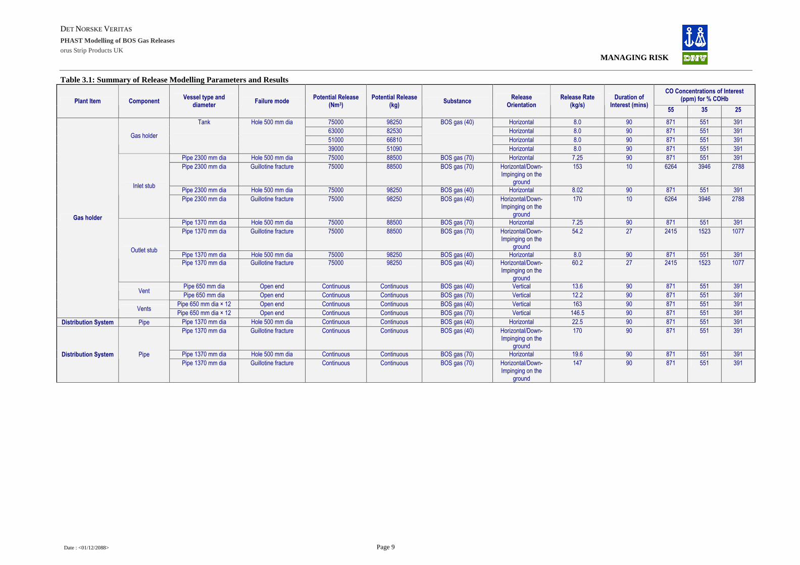
The results are summarised in Table 3.1 (original scenarios) and Table 3.2 (new cases).
3.2 Consequences
The consequence results for the hazard levels of interest are summarised in Table 3.3. The results are presented for the hazards levels set out in Section 2.2. Side views of the dispersion, showing the hazard levels of interest, are presented in Appendix II. New cases are summarised in Table 3.4 and Appendix III.
The values given are for the worst-case outcomes for the different weather categories and release orientations considered (as indicated in the brackets): see footnote to the table.
A brief discussion of the results is provided in Section 4.

DET NORSKE VERITAS
PHAST Modelling of BOS Gas Releases
Corus Strip Products UK
MANAGING RISK
Date : <01/12/2088> Page 8
(this page left blank)
DET NORSKE VERITAS
PHAST Modelling of BOS Gas Releases
orus Strip Products UK
MANAGING RISK
Date : <01/12/2088> Page 9
Table 3.1: Summary of Release Modelling Parameters and Results CO Concentrations of Interest
(ppm) for % COHb Plant Item Component Vessel type and
diameter Failure mode
Potential Release (Nm3)
Potential Release (kg)
Substance Release
Orientation Release Rate
(kg/s) Duration of
Interest (mins) 55 35 25
75000 98250 Horizontal 8.0 90 871 551 391
63000 82530 Horizontal 8.0 90 871 551 391
51000 66810 Horizontal 8.0 90 871 551 391 Gas holder
Tank
Hole 500 mm dia
39000 51090
BOS gas (40)
Horizontal 8.0 90 871 551 391
Pipe 2300 mm dia Hole 500 mm dia 75000 88500 BOS gas (70) Horizontal 7.25 90 871 551 391
Pipe 2300 mm dia Guillotine fracture 75000 88500 BOS gas (70) Horizontal/Down-Impinging on the
ground
153 10 6264 3946 2788
Pipe 2300 mm dia Hole 500 mm dia 75000 98250 BOS gas (40) Horizontal 8.02 90 871 551 391 Inlet stub
Pipe 2300 mm dia Guillotine fracture 75000 98250 BOS gas (40) Horizontal/Down-Impinging on the
ground
170 10 6264 3946 2788
Pipe 1370 mm dia Hole 500 mm dia 75000 88500 BOS gas (70) Horizontal 7.25 90 871 551 391
Pipe 1370 mm dia Guillotine fracture 75000 88500 BOS gas (70) Horizontal/Down-Impinging on the
ground
54.2 27 2415 1523 1077
Pipe 1370 mm dia Hole 500 mm dia 75000 98250 BOS gas (40) Horizontal 8.0 90 871 551 391 Outlet stub
Pipe 1370 mm dia Guillotine fracture 75000 98250 BOS gas (40) Horizontal/Down-Impinging on the
ground
60.2 27 2415 1523 1077
Pipe 650 mm dia Open end Continuous Continuous BOS gas (40) Vertical 13.6 90 871 551 391 Vent
Pipe 650 mm dia Open end Continuous Continuous BOS gas (70) Vertical 12.2 90 871 551 391
Pipe 650 mm dia × 12 Open end Continuous Continuous BOS gas (40) Vertical 163 90 871 551 391
Gas holder
Vents Pipe 650 mm dia × 12 Open end Continuous Continuous BOS gas (70) Vertical 146.5 90 871 551 391
Distribution System Pipe Pipe 1370 mm dia Hole 500 mm dia Continuous Continuous BOS gas (40) Horizontal 22.5 90 871 551 391
Pipe 1370 mm dia Guillotine fracture Continuous Continuous BOS gas (40) Horizontal/Down-Impinging on the
ground
170 90 871 551 391
Pipe 1370 mm dia Hole 500 mm dia Continuous Continuous BOS gas (70) Horizontal 19.6 90 871 551 391 Distribution System Pipe
Pipe 1370 mm dia Guillotine fracture Continuous Continuous BOS gas (70) Horizontal/Down-Impinging on the
ground
147 90 871 551 391

DET NORSKE VERITAS
PHAST Modelling of BOS Gas Releases
orus Strip Products UK
MANAGING RISK
Date : <01/12/2088> Page 10
CO Concentrations of Interest (ppm) for % COHb Plant Item Component
Vessel type and diameter
Failure mode Potential Release
(Nm3) Potential Release
(kg) Substance
Release Orientation
Release Rate (kg/s)
Duration of Interest (mins)
55 35 25
Pipe 2300 mm dia Hole 500 mm dia 75000 88500 BOS gas (70) Horizontal 7.25 90 871 551 391
88500 Horizontal 7.25 90 871 551 391
Pipe 2300 mm dia Guillotine fracture 75000 88500 BOS gas (70) Horizontal/Down-Impinging on the
ground 153 10 6264 3946 2788
88500 Horizontal/Down-Impinging on the
ground 153 10 6264 3946 2788
Pipe 2300 mm dia Hole 500 mm dia 75000 98250 BOS gas (40) Horizontal 8.0 90 871 551 391
Pipe
Pipe 2300 mm dia Guillotine fracture 75000 98250 BOS gas (40) Horizontal/Down-Impinging on the
ground 170 10 6264 3946 2788
Pipe 2300 mm dia Hole 500 mm dia 75000 88500 BOS gas (70) Horizontal 7.25 90 871 551 391
Pipe 2300 mm dia Guillotine fracture 75000 88500 BOS gas (70) Horizontal/Down-Impinging on the
ground 153 10 6264 3946 2788
Pipe 2300 mm dia Hole 500 mm dia 75000 98250 BOS gas (40) Horizontal 8.0 90 871 551 391
Collection system
Cooler outlet
Pipe 2300 mm dia Guillotine fracture 75000 98250 BOS gas (40) Horizontal/Down-Impinging on the
ground
170 10 6264 3946 2788

DET NORSKE VERITAS
PHAST Modelling of BOS Gas Releases
orus Strip Products UK
MANAGING RISK
Date : <01/12/2088> Page 11
Table 3.2: Summary of Release Modelling Parameters and Results (New Cases) CO Concentrations of Interest
(ppm) for % COHb Plant Item Component
Vessel type and diameter
Failure mode Potential release
(Nm3) Potential Release
(kg) Substance
Release Orientation
Release Rate (kg/s)
Duration of Interest (mins)
55 35 25
Hole 500 mm dia 86000 101480 BOS gas (70) Horizontal 7.25 233 478 303 216
Hole 500 mm dia 86000 112660 BOS gas (40) Horizontal 8.0 234 476 303 216 Gas Holder
(shell) Tank
Hole 500 mm dia 86000 116100 BOS gas (20) Horizontal 8.4 231 481 305 217
101480 Horizontal 7.25 233 478 303 216
112660 Horizontal 8.0 234 476 303 216 Inlet Stub Pipe 2300 mm dia Hole 500 mm dia 86000
116100
BOS gas (70, 40, 20)
Horizontal 8.4 231 481 305 217
101480 Horizontal 7.25 233 478 303 216
112660 Horizontal 8.0 234 476 303 216 Outlet stub Pipe 1200 mm dia Hole 500 mm dia 86000
116100
BOS gas (70, 40, 20)
Horizontal 8.4 231 481 305 217
Vent Pipe 650 mm dia Open end - 30 min Furnace Gas Vertical 22.8 30 2212 1395 987
Gas Holder
Vents Pipe 650 mm dia x 12 Open end - 30 min Furnace Gas Vertical 273.8 30 2212 1395 987
BOS gas (70) 22.5 86 902 570 405
BOS gas (40) 26.2 74 1015 641 455 116000
BOS gas (20) 27.6 70 1061 670 475
BOS gas (70) 22.5 35 1924 1214 859
BOS gas (40) 26.2 35 1924 1214 859
Distribution system Pipe Pipe 1200 mm dia Hole 500 mm dia -
35 min release
BOS gas (20)
Horizontal
27.6 35 1924 1214 859

DET NORSKE VERITAS
PHAST Modelling of BOS Gas Releases
orus Strip Products UK
MANAGING RISK
Date : <01/12/2088> Page 12
Table 3.3: Summary of Worst-Case Consequence Results Distance (m) to CO Concentrations (m) for %
COHb Downwind Distance
(m) to Distance (m) to Jet Fire Radiation Level
(kW/m2) Distance (m) to
Overpressure Level (psi) Plant Item Component Vessel type and
diameter Failure mode Substance
Release height (m)
Reference Figure
55 35 25 LFL ½ LFL 37.5 12.5 4 5 3 1
1 Figure II.1 162 (5D) 197 (5D) 245 (5D) 7.0 (2F) 17.5 (2F) No Hazard at ground level
34 (2F) 41 (2F) 13 14 18
5 150 (2F) 177 (2F) 200 (2F) 8.0 (2F) 17 (2F) No Hazard at ground level
33 (2F) 40 (2F) 13 14 18
10 No Hazard at ground level
137 (2F) 161 (2F) 8.5 (2F) 17 (2F) No Hazard at ground level
No Hazard at ground level
36 (2F) 13 14 18
Gas holder Tank Hole 500 mm dia BOS gas
(40)
15 No Hazard at ground level
No Hazard at ground level
No Hazard at ground level
8.5 (2F) 17.5 (2F) No Hazard at ground level
No Hazard at ground level
28 (2F) 13 14 18
Pipe 2300 mm dia Hole 500 mm dia BOS gas (70)
2 Figure II.2 83 (5D) 95 (5D) 105 (5D) 5 (2F) 10.5 (2F) No Hazard at ground level
32 (2F) 39 (2F) 12 13 16
Pipe 2300 mm dia Guillotine fracture BOS gas
(70) 2 Figure II.3 92 (5D, H) 112 (5D, H) 130 (5D, H) 29 (2F, D) 53 (2F, H) 84 (5D, H) 124 (2F, H) 148 (2F, H) 59 (H) 62 (H) 75 (H)
Pipe 2300 mm dia Hole 500 mm dia BOS gas (40)
2 Figure II.4 187 (5D) 210 (5D) 240 (5D) 8.0 (2F) 15.0 (2F) No Hazard at ground level
34 (2F) 41 (2F) 13 14 18
Inlet stub
Pipe 2300 mm dia Guillotine fracture BOS gas
(40) 2 Figure II.5 460 (5D, D) 603 (5D, D) 738 (5D, D) 89 (5D, D) 160 (5D, D) 108 (2F, H) 130 (2F, H) 156 (2F, H) 174 (D) 182 (D) 215 (D)
Pipe 1370 mm dia Hole 500 mm dia BOS gas (70)
2 As
Figure II.2 83 (5D) 95 (5D) 105 (5D) 5 (2F) 10.5 (2F)
No Hazard at ground level
33 (2F) 39 (2F) 12 13 16
Pipe 1370 mm dia Guillotine fracture BOS gas (70)
1 Figure II.6 305 (5D, D) 400 (5D, D) 500 (5D, D) 30 (5D, D) 51 (5D, D) No Hazard at ground level
79 (2F, H) 94 (2F, H) 60 (D) 64 (D) 78 (D)
Pipe 1370 mm dia Hole 500 mm dia BOS gas (40)
2 As
Figure II.4 187 (5D) 210 (5D) 240 (5D) 8.0 (2F) 15.0 (2F)
No Hazard at ground level
34 (2F) 41 (2F) 13 14 18
Outlet stub
Pipe 1370 mm dia Guillotine fracture BOS gas
(40) 1 Figure II.7 440 (5D, D) 560 (5D, D) 680 (5D, D) 60 (5D, D) 110 (5D, D) 57 (5D, H) 83 (2F, H) 100 (2F, H) 115 (D) 121 (D) 142 (D)
Pipe 650 mm dia Open end BOS gas (40)
52 Figure II.8 No Hazard at ground level
No Hazard at ground level
No Hazard at ground level
<1 <3 No Hazard at ground level
No Hazard at ground level
No Hazard at ground level
- - -
Vent
Pipe 650 mm dia Open end BOS gas (70)
52 Figure II.9 No Hazard at ground level
No Hazard at ground level
No Hazard at ground level
<1 <2 No Hazard at ground level
No Hazard at ground level
No Hazard at ground level
- - -
Pipe 650 mm dia × 12 Open end BOS gas (40)
52 Figure II.10 No Hazard at ground level
No Hazard at ground level
No Hazard at ground level
3 7 No Hazard at ground level
No Hazard at ground level
No Hazard at ground level
- - -
Gas holder
Vents
Pipe 650 mm dia × 12 Open end BOS gas (70)
52 Figure II.11 No Hazard at ground level
No Hazard at ground level
No Hazard at ground level
2 6 No Hazard at ground level
No Hazard at ground level
No Hazard at ground level
- - -
Pipe 1370 mm dia Hole 500 mm dia BOS gas
(40) 2 Figure II.12 480 (5D) 540 (5D) 590 (5D) 9.0 (2F) 17 (2F) 41 (2F) 48 (2F) 57 (2F) 13 14 18
Pipe 1370 mm dia Guillotine fracture BOS gas
(40) 2 Figure II.13 1330 (5D, D) 1685 (5D, D) 2020 (5D, D) 94 (5D, D) 187 (5D, D) 101 (2F, H) 117 (2F, H) 140 (2F, H) 199 (D) 205 (D) 232 (D)
Pipe 1370 mm dia Hole 500 mm dia BOS gas
(70) 2 Figure II.14 193 (5D) 230 (5D) 260 (5D) 6 (2F) 13.0 (2F) 32 (5D) 45 (2F) 53 (2F) 12 13 16
Distribution System Pipe
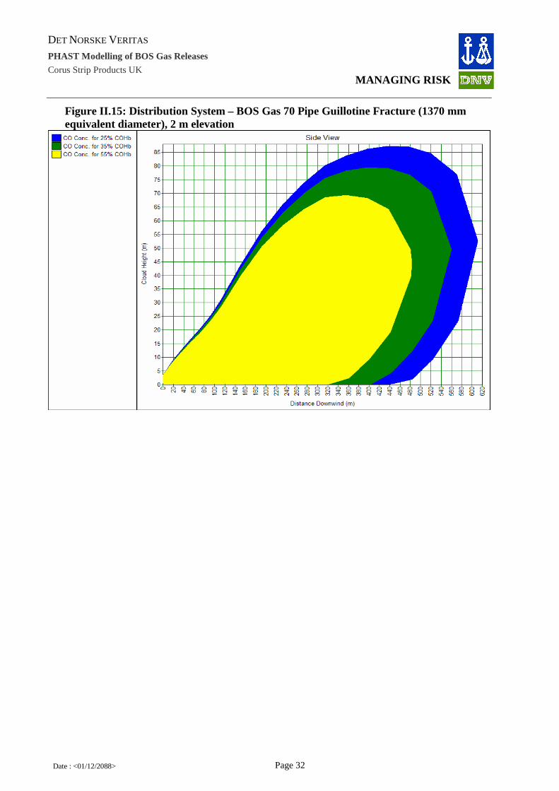
Pipe 1370 mm dia Guillotine fracture BOS gas
(70) 2 Figure II.15 350 (5D, H) 420 (5D, H) 475 (5D, H) 52 (5D, D) 90 (5D, D) 94 (2F, H) 110 (2F, H) 130 (2F, H) 93 (D) 98 (D) 116 (D)

DET NORSKE VERITAS
PHAST Modelling of BOS Gas Releases
orus Strip Products UK
MANAGING RISK
Date : <01/12/2088> Page 13
Distance (m) to CO Concentrations (m) for % COHb
Downwind Distance (m) to
Distance (m) to Jet Fire Radiation Level (kW/m2)
Distance (m) to Overpressure Level (psi) Plant Item Component
Vessel type and diameter
Failure mode Substance Release height (m)
Reference Figure
55 35 25 LFL ½ LFL 37.5 12.5 4 5 3 1
2 As
Figure II.2 83 (5D) 95 (5D) 105 (5D) 5 (2F) 11 (2F)
No Hazard at ground level
33 (2F) 39 (2F) 12 13 16 Pipe 2300 mm dia
Hole 500 mm dia
BOS gas
(70) 8 Figure II.16
No Hazard at ground level
No Hazard at ground level
No Hazard at ground level
5.0 (2F) 12.0 (2F) No Hazard at ground level
No Hazard at ground level
35 (2F) 12 13 15
2 As
Figure II.3 92 (5D, H) 112 (5D, H) 130 (5D, H) 29 (2F, D) 53 (2F, H) 84 (5D, H) 124 (2F, H) 148 (2F, H) 59 (H) 62 (H) 75 (H)
Pipe 2300 mm dia Guillotine fracture BOS gas
(70) 8 Figure II.17 52 (5D, D) 75 (5D, H) 100 (5D, H) 29 (2F, D) 47 (2F, H) 83 (5D, H) 123 (2F, H) 147 (2F, H) 49 (H) 51 (H/D) 72 (D)
Pipe 2300 mm dia Hole 500 mm dia BOS gas
(40) 8 Figure II.18 125 (2F) 152 (2F) 170 (2F) 9.0 (2F) 17 (2F)
No Hazard at ground level
No Hazard at ground level
38 (2F) 13 14 18
Pipe
Pipe 2300 mm dia Guillotine fracture BOS gas
(40) 8
As Figure II.5
460 (5D, D) 603 (5D, D) 738 (5D, D) 89 (5D, D) 160 (5D, D) 108 (2F, H) 129 (2F, H) 156 (2F, H) 174 (D) 182 (D) 215 (D)
Pipe 2300 mm dia Hole 500 mm dia BOS gas
(70) 18 Figure II.19
No Hazard at ground level
No Hazard at ground level
No Hazard at ground level
6.0 (2F) 13.0 (2F) No Hazard at ground level
No Hazard at ground level
No Hazard at ground level
12 13 15
Pipe 2300 mm dia Guillotine fracture BOS gas
(70) 18 Figure II.20 52 (5D, D) 61 (5D, D) 70 (5D, D) 29 (2F, D) 48 (2F, H) 82 (5D, H) 115 (2F, H) 142 (2F, H) 49 (H) 52 (H) 72 (D)
Pipe 2300 mm dia Hole 500 mm dia BOS gas
(40) 18 Figure II.21
No Hazard at ground level
No Hazard at ground level
No Hazard at ground level
9 (2F) 18 (2F) No Hazard at ground level
No Hazard at ground level
18 (2F) 13 14 18
Collection system
Cooler outlet
Pipe 2300 mm dia Guillotine fracture BOS gas
(40) 18
As Figure II.5
460 (5D, D) 603 (5D, D) 738 (5D, D) 89 (5D, D) 160 (5D, D) 105 (2F, H) 122 (2F, H) 152 (2F, H) 174 (D) 182 (D) 215 (D)
Notes: 1. Distances given are for worst-case results (weather category in parentheses). 2. Distances to toxic concentrations of interest and radiation levels given at 1.5 m elevation. 3. Maximum downwind distances to LFL, 1/2 LFL are given at the cloud centreline height. 4. Explosion modelling conducted with PHAST, using the TNT explosion model.

DET NORSKE VERITAS
PHAST Modelling of BOS Gas Releases
orus Strip Products UK
MANAGING RISK
Date : <01/12/2088> Page 14
Table 3.4: Summary of Worst-Case Consequence Results (New Cases)
Distance to CO Concentrations (m) for % COHb Downwind Distance to
(m) Distance (m) to Jet Fire Radiation Level (kW/m2)
Distance [m] Overpressure (psi)
Plant Item Component Vessel type and diameter
Failure mode Substance Temperature Release height (m)
Reference Figure
55 35 25 LFL 1/2 LFL 37.5 12.5 4 5 3 1
1 Figure III.1 103 (5D) 133 (5D) 172 (5D) 4.81 (2F) 10.82 (2F) No Hazard at ground level
32.1 (2F) 38.3 (2F) 11.8 12.5 15.0
5 Figure III.2 93 (5D) 121 (5D) 167 (5D) 4.99 (2F) 11.02 (2F) No Hazard at ground level
31 (2F) 37.3 (2F) 11.8 12.4 15.0
10 Figure III.3 No Hazard at ground level
No Hazard at ground level
93 (5D) 5.07 (2F) 11.61 (2F) No Hazard at ground level
No Hazard at ground level
32.3 (2F) 11.8 12.4 15.0
Hole 500 mm dia
BOS gas 70ºC
15 Figure III.4 No Hazard at ground level
No Hazard at ground level
No Hazard at ground level
5.12 (2F) 11.97 (2F) No Hazard at ground level
No Hazard at ground level
No Hazard at ground level
11.8 12.4 15.0
1 Figure III.5 229 (5D) 296 (5D) 359 (5D) 6.87 (2F) 17.34 (2F) No Hazard at ground level
33.9 (2F) 40.6 (2F) 12.4 13.3 16.8
5 Figure III.6 197 (2F) 242 (5D) 306 (5D) 8.01 (2F) 16.23 (2F) No Hazard at ground level
32.7 (2F) 39.7 (2F) 12.7 13.6 17.5
10 Figure III.7 158 (2F) 182 (2F) 229 (5D) 8.23 (2F) 16.87 (2F) No Hazard at ground level
No Hazard at ground level
35.2 (2F) 12.7 13.6 17.4
Hole 500 mm dia
BOS gas 40ºC
15 Figure III.8 No Hazard at ground level
No Hazard at ground level
No Hazard at ground level
8.37 (2F) 17.26 (2F) No Hazard at ground level
No Hazard at ground level
27.7 (2F) 12.7 13.6 17.4
1 Figure III.9 1114 (2F) 1602 (2F) 2073 (2F) 7.98 (2F) 20.03 (2F) No Hazard at ground level
51.4 (5D) 53.4 (5D) 22.8 23.8 27.7
5 Figure III.10 856 (2F) 1284 (2F) 1705 (2F) 8.89 (2F) 17.64 (2F) No Hazard at ground level
No Hazard at ground level
51.9 (5D) 12.9 14.0 18.1
10 Figure III.11 528 (2F) 884 (2F) 1241 (2F) 9.11 (2F) 18.3 (2F) No Hazard at ground level
No Hazard at ground level
40.1 (5D) 12.9 14.0 18.1
Gas Holder (shell)
Tank
Hole 500 mm dia
BOS gas 20ºC
15 Figure III.12 277 (2F) 531 (2F) 832 (2F) 9.25 (2F) 18.7 (2F) No Hazard at ground level
No Hazard at ground level
No Hazard at ground level
12.9 13.9 18.0
70ºC 1 As
Figure III.1 103 (5D) 133 (5D) 172 (5D) 4.81 (2F) 10.82 (2F)
No Hazard at ground level
32.1 (2F) 38.3 (2F) 11.8 12.5 15.0
40ºC 1 As
Figure III.5 229 (5D) 296 (5D) 359 (5D) 6.87 (2F) 17.34 (2F)
No Hazard at ground level
33.9 (2F) 40.6 (2F) 12.4 13.3 16.8 Inlet Stub Pipe 2300 mm
dia Hole 500 mm
dia BOS gas
20ºC 1 As
Figure III.9 1114 (2F) 1602 (2F) 2073 (2F) 7.98 (2F) 20.03 (2F)
No Hazard at ground level
51.4 (5D) 53.4 (5D) 22.8 23.8 27.7
70ºC 2.2 Figure III.13 110 (5D) 137(5D) 175 (5D) 4.9 (2F) 10.25 (2F) No Hazard at ground level
32.1 (2F) 38.3 (2F) 11.8 12.4 15.0
40ºC 2.2 Figure III.14 225 (5D) 292 (5D) 356(5D) 7.75 (2F) 14.33 (2F) No Hazard at ground level
33.9 (2F) 40.6 (2F) 12.7 13.6 17.5 Outlet stub Pipe 1200 mm
dia Hole 500 mm
dia BOS gas
20ºC 2.2 Figure III.15 1038 (2F) 1522 (2F) 1988 (2F) 8.62 (2F) 15.45 (2F) No Hazard at ground level
51.3 (5D) 53.3 (5D) 12.9 14.0 18.1
Vent Pipe 650 mm
dia Open end
Furnace Gas
20ºC 52 Figure III.16 No Hazard at ground level
No Hazard at ground level
No Hazard at ground level
<1 <1 No Hazard at ground level
No Hazard at ground level
No Hazard at ground level
- - -
Gas Holder
Vents Pipe 650 mm
dia x 12 Open end
Furnace Gas
20ºC 52 Figure III.17 No Hazard at ground level
No Hazard at ground level
No Hazard at ground level
<1 2.5 (5D) No Hazard at ground level
No Hazard at ground level
No Hazard at ground level
- - -

DET NORSKE VERITAS
PHAST Modelling of BOS Gas Releases
orus Strip Products UK
MANAGING RISK
Date : <01/12/2088> Page 15
Distance to CO Concentrations (m) for % COHb Downwind Distance to
(m) Distance (m) to Jet Fire Radiation Level (kW/m2)
Distance [m] Overpressure (psi)
Plant Item Component Vessel type and diameter
Failure mode Substance Temperature Release height (m)
Reference Figure
55 35 25 LFL 1/2 LFL 37.5 12.5 4 5 3 1
8 Figure III.18 195 (5D) 241 (5D) 275 (5D) 6.02 (2F) 14.29 (2F) No Hazard at ground level
41.6 (2F) 52.3 (2F) 11.9 12.6 15.2
10 Figure III.19 165 (5D) 238 (5D) 279 (5D) 6.04 (2F) 14.37 (2F) No Hazard at ground level
No Hazard at ground level
50.7 (2F) 11.9 12.6 15.2 BOS gas 70ºC
16 Figure III.20 No Hazard at ground level
No Hazard at ground level
166 (5D) 6.1 (2F) 14.54 (2F) No Hazard at ground level
No Hazard at ground level
45.7 (2F) 11.9 12.6 15.3
8 Figure III.21 494 (2F) 629 (2F) 712 (2F) 8.89 (2F) 18.83 (2F) 40.8 (2F) 46.2 (2F) 57.4 (2F) 12.8 13.8 17.8
10 Figure III.22 468 (2F) 613 (2F) 698 (2F) 8.92 (2F) 18.91 (2F) No Hazard at ground level
44.1 (2F) 56.1 (2F) 12.8 13.8 17.8 BOS gas 40ºC
16 Figure III.23 345 (2F) 537 (2F) 629 (2F) 8.97 (2F) 19.08 (2F) No Hazard at ground level
26 (5D) 52.3 (2F) 12.8 13.8 17.8
8 Figure III.24 1224 (2F) 1483 (2F) 1680 (2F) 9.72 (2F) 20.09 (2F) No Hazard at ground level
55.2 (5D) 64.1 (5D) 23.1 24.2 28.5
10 Figure III.25 1211 (2F) 1481 (2F) 1682 (2F) 9.75 (2F) 20.17 (2F) No Hazard at ground level
No Hazard at ground level
63.3 (5D) 23.0 24.2 28.5 BOS gas 20ºC
16 Figure III.26 1069 (2F) 293 (5D) 1632 (2F) 9.8 (2F) 20.24 (2F) No Hazard at ground level
No Hazard at ground level
56.5 (5D) 23.0 24.2 28.5
8 Figure III.27 105 (5D) 173 (5D) 210 (5D) 6.02 (2F) 14.29 (2F) No Hazard at ground level
41.6 (2F) 52.3 (2F) 11.9 12.6 15.2
10 Figure III.28 No Hazard at ground level
130 (5D) 177 (5D) 6.04 (2F) 14.37 (2F) No Hazard at ground level
No Hazard at ground level
50.7 (2F) 11.9 12.6 15.2 BOS gas 70ºC
16 Figure III.29 No Hazard at ground level
No Hazard at ground level
No Hazard at ground level
6.1 (2F) 14.54 (2F) No Hazard at ground level
No Hazard at ground level
45.7 (2F) 11.9 12.6 15.3
8 Figure III.30 328 (2F) 443 (2F) 544 (2F) 8.89 (2F) 18.83 (2F) 40.8 (2F) 46.2 (2F) 57.4 (2F) 12.8 13.8 17.8
10 Figure III.31 288 (2F) 414 (2F) 521 (2F) 8.92 (2F) 18.91 (2F) No Hazard at ground level
44.1 (2F) 56.1 (2F) 12.8 13.8 17.8 BOS gas 40ºC
16 Figure III.32 No Hazard at ground level
268 (2F) 415 (2F) 8.97 (2F) 19.08 (2F) No Hazard at ground level
26 (5D) 52.3 (2F) 12.8 13.8 17.8
8 Figure III.33 866 (2F) 1150 (2F) 1341 (2F) 9.72 (2F) 20.09 (2F) No Hazard at ground level
55.2 (5D) 64.1 (5D) 23.1 24.2 28.5
10 Figure III.34 798 (2F) 1135 (2F) 1334 (2F) 9.75 (2F) 20.17 (2F) No Hazard at ground level
No Hazard at ground level
63.3 (5D) 23.0 24.2 28.5
Distribution system
Pipe Pipe 1200 mm
dia Hole 500 mm
dia
BOS gas 20ºC
16 Figure III.35 300 (2F) 880 (2F) 1225 (2F) 9.8 (2F) 20.24 (2F) No Hazard at ground level
No Hazard at ground level
56.5 (5D) 23.0 24.2 28.5
Notes: 1. Distances given are for worst-case results (weather category in parentheses). 2.Distances to toxic concentrations of interest and radiation levels given at 1.5 m elevation. 3. Maximum downwind distances to LFL, 1/2 LFL are given at the cloud centreline height. 4. Explosion modelling conducted with PHAST, using the TNT explosion model.

DET NORSKE VERITAS
PHAST Modelling of BOS Gas Releases
orus Strip Products UK
MANAGING RISK
Date : <01/12/2088> Page 16
(this page left blank)

DET NORSKE VERITAS
PHAST Modelling of BOS Gas Releases
Corus Strip Products UK
MANAGING RISK
Date : <01/12/2088> Page 17
4 DISCUSSION
The scope of this study was to model the consequences associated with the defined scenarios only, rather than to assess the implications with respect to affected populations or equipment. Similarly, the uncertainty/sensitivity in the results is intended to be covered by the number of different scenarios modelled. However, the key influences are briefly summarised as follows:
• Composition: The BOS gas at ‘40°C – saturated’ has a higher carbon monoxide content than the equivalent ‘70°C – saturated’, which is reflected by the higher distances to CO concentrations of interest, as indicated in the results table. The BOS gas at ‘20°C – saturated’ has even a higher carbon monoxide content than the equivalent ’40°C and 70°C – saturated’. This is reflected by the higher distances to the CO concentrations of interest.
• Weather conditions/atmospheric parameters: At the specified release conditions (for all cases modelled), the gas clouds are more buoyant than air, but buoyancy effects are dominant earlier for the F2 weather conditions than for the D5 conditions. This means that cloud lift-off occurs earlier for the F2 conditions than for the D5 conditions. Hence the dispersion distances at ground level or 1.5 m tend to be greater in D5 weather conditions, except for the 20°C BOS Gas. This effect is due to the greater turbulence in D5 conditions leading to the cloud being diluted from just under to just above the air density as the cloud cools down, whereas the cloud remains buoyant (i.e. just below the density of air) in the less turbulent F2 conditions. 20°C BOS Gas is slightly heavier than air; cloud lift-off phenomenon is not present and therefore the cloud is more effectively dispersed in the more turbulent D5 conditions.
• It should be noted that the buoyancy and hence the dispersion results are sensitive to different atmospheric parameters, such as ambient temperature, relative humidity and surface roughness.
• Release Hole Size: The maximum distances for the various hazard levels reported are dominated by guillotine fracture releases, as these result in much higher release rates compared to releases from smaller leak hole sizes (i.e. 2.3 m equivalent diameter for guillotine fractures compared to 0.5 m equivalent diameter for leaks).
The hazard ranges presented in Table 3.3 and Table 3.4 are summarised as follows:
• The worst-case hazard range to the lowest CO concentration of interest may exceed 2 km for only one case, a guillotine fracture of a 1370 mm diameter pipe from the distribution system, for a BOS Gas 40°C release (with a downwards release orientation). As mentioned previously, the dispersion distance will generally be sensitive to the specified atmospheric parameters. The worst-case hazard range to the lowest CO concentration of interest for a BOS Gas 20°C release.may exceed 2km for the BOS Gas release from the gas holder system. The other toxic hazard ranges are generally below (and in most cases substantially below) 1 km.
• The distances to the toxic CO concentrations of interest dominate the hazard ranges, noting that the hazard ranges of potential flammable cloud, jet fire thermal radiation and explosion overpressures are generally predicted to be less than 200 m for the majority of the cases considered. The predicted hazard ranges for these are likely to be conservative on the basis that:

DET NORSKE VERITAS
PHAST Modelling of BOS Gas Releases
Corus Strip Products UK
MANAGING RISK
Date : <01/12/2088> Page 18
(a) Low release pressures for all the scenarios modelled result in relatively low release velocities that would not be able to sustain a stable jet flame; and
(b) Overpressure levels are based on treating the whole cloud as an explosive mass.

DET NORSKE VERITAS
PHAST Modelling of BOS Gas Releases
Corus Strip Products UK
MANAGING RISK
Date : <01/12/2088> Page 19
APPENDIX I: DERIVATION OF CO CONCENTRATIONS OF INTE REST
These are determined using the CFK equation as referenced in the Port Talbot Establishment Safety Report. This equation describes the relationship between atmospheric CO concentration and percentage carboxyhaemoglobin (%COHb) in the blood.
TIME TIME TIME ppm CO
MINS % COHb
ppm CO
MINS % COHb
ppm CO
MINS % COHb
5491 5 25% 7776 5 35% 12346 5 55%
2788 10 25% 3946 10 35% 6264 10 55%
1887 15 25% 2670 15 35% 4237 15 55%
1437 20 25% 2033 20 35% 3224 20 55%
1167 25 25% 1650 25 35% 2617 25 55%
987 30 25% 1395 30 35% 2212 30 55%
859 35 25% 1214 35 35% 1924 35 55%
762 40 25% 1077 40 35% 1707 40 55%
688 45 25% 971 45 35% 1539 45 55%
628 50 25% 887 50 35% 1405 50 55%
579 55 25% 818 55 35% 1295 55 55%
539 60 25% 760 60 35% 1204 60 55%
504 65 25% 712 65 35% 1127 65 55%
475 70 25% 670 70 35% 1061 70 55%
450 75 25% 634 75 35% 1003 75 55%
427 80 25% 603 80 35% 954 80 55%
408 85 25% 575 85 35% 910 85 55%
391 90 25% 551 90 35% 871 90 55%
318 120 25% 447 120 35% 707 120 55%
274 150 25% 386 150 35% 609 150 55% 246 180 25% 346 180 35% 547 180 55% 227 210 25% 319 210 35% 503 210 55% 213 240 25% 299 240 35% 471 240 55%

DET NORSKE VERITAS
PHAST Modelling of BOS Gas Releases
Corus Strip Products UK
MANAGING RISK
Date : <01/12/2088> Page 20
APPENDIX II: WORST-CASE DISPERSION TO CO CONCENTRAT IONS OF INTEREST
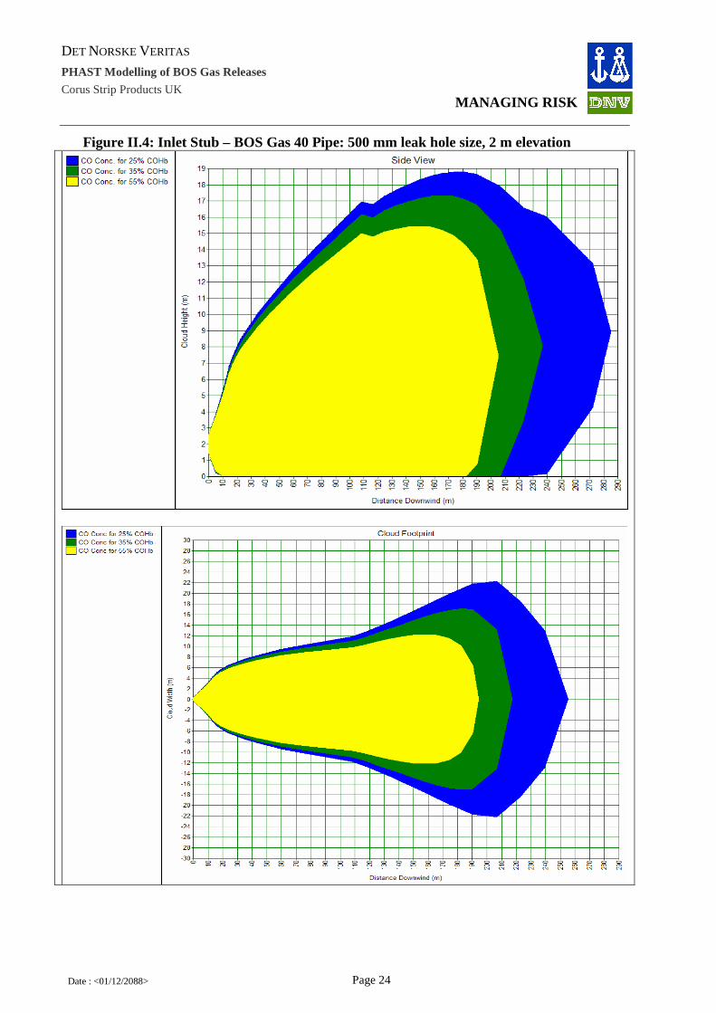
Side views and footprints (at 1.5 m height for scenarios affecting the ground and at the release height for scenario not affecting the ground) of the worst case cloud dispersion (as presented in Table 3.3) to the CO concentrations of interest (corresponding to 25%, 35% and 55% COHb in the bloodstream) are presented below for each scenario modelled. Footprints are provided only for the leak cases (not for guillotine ruptures)

DET NORSKE VERITAS
PHAST Modelling of BOS Gas Releases
Corus Strip Products UK
MANAGING RISK
Date : <01/12/2088> Page 21
II.1 Gas Holder
Figure II.1: Gas Holder - BOS Gas 40 Tank: 500 mm leak hole size, 1m elevation

DET NORSKE VERITAS
PHAST Modelling of BOS Gas Releases
Corus Strip Products UK
MANAGING RISK
Date : <01/12/2088> Page 22
Figure II.2: Inlet Stub – BOS Gas 70 Pipe: 500 mm leak hole size, 2m elevation

DET NORSKE VERITAS
PHAST Modelling of BOS Gas Releases
Corus Strip Products UK
MANAGING RISK
Date : <01/12/2088> Page 23
Figure II.3: Inlet Stub – BOS Gas 70 Pipe Guillotine Fracture (2300 mm equivalent diameter), 2m elevation
DET NORSKE VERITAS
PHAST Modelling of BOS Gas Releases
Corus Strip Products UK
MANAGING RISK
Date : <01/12/2088> Page 24
Figure II.4: Inlet Stub – BOS Gas 40 Pipe: 500 mm leak hole size, 2 m elevation

DET NORSKE VERITAS
PHAST Modelling of BOS Gas Releases
Corus Strip Products UK
MANAGING RISK
Date : <01/12/2088> Page 25
Figure II.5: Inlet Stub – BOS Gas 40 Pipe Guillotine Fracture (2300 mm equivalent diameter), 0m elevation
Outlet Stub – BOS Gas 70 Pipe: 500 mm leak hole size, 2 m elevation: Results as for Figure II.2.

DET NORSKE VERITAS
PHAST Modelling of BOS Gas Releases
Corus Strip Products UK
MANAGING RISK
Date : <01/12/2088> Page 26
Figure II.6: Outlet Stub – BOS Gas 70 Pipe Guillotine Fracture (1370 mm equivalent diameter), 0m elevation
Outlet Stub – BOS Gas 40 Pipe: 500 mm leak hole size, 2 m elevation: Results as for Figure II.4.
Figure II.7: Outlet Stub – BOS Gas 40 Pipe Guillotine Fracture (1370 mm equivalent diameter), 0m elevation

DET NORSKE VERITAS
PHAST Modelling of BOS Gas Releases
Corus Strip Products UK
MANAGING RISK
Date : <01/12/2088> Page 27
Figure II.8: Open End Vent, 650 mm equivalent diameter, BOS Gas 40, 52 m elevation (No hazard at ground level)
Figure II.9: Open End Vent, 650 mm equivalent diameter, BOS Gas 70, 52 m elevation (No hazard at ground level)

DET NORSKE VERITAS
PHAST Modelling of BOS Gas Releases
Corus Strip Products UK
MANAGING RISK
Date : <01/12/2088> Page 28
Figure II.10: Open End Vent, 2252 mm equivalent diameter, BOS Gas 40, 52 m elevation (No hazard at ground level)
Figure II.11: Open End Vent, 2252 mm equivalent diameter, BOS Gas 70, 52 m elevation (No hazard at ground level)

DET NORSKE VERITAS
PHAST Modelling of BOS Gas Releases
Corus Strip Products UK
MANAGING RISK
Date : <01/12/2088> Page 29
II.2 Distribution System
Figure II.12: Distribution System – BOS Gas 40 Pipe: 500 mm leak hole size, 2 m elevation

DET NORSKE VERITAS
PHAST Modelling of BOS Gas Releases
Corus Strip Products UK
MANAGING RISK
Date : <01/12/2088> Page 30
Figure II.13: Distribution System – BOS Gas 40 Pipe Guillotine Fracture (1370 mm equivalent diameter), 0 m elevation

DET NORSKE VERITAS
PHAST Modelling of BOS Gas Releases
Corus Strip Products UK
MANAGING RISK
Date : <01/12/2088> Page 31
Figure II.14: Distribution System – BOS Gas 70 Pipe: 500 mm leak hole size, 2 m elevation
DET NORSKE VERITAS
PHAST Modelling of BOS Gas Releases
Corus Strip Products UK
MANAGING RISK
Date : <01/12/2088> Page 32
Figure II.15: Distribution System – BOS Gas 70 Pipe Guillotine Fracture (1370 mm equivalent diameter), 2 m elevation

DET NORSKE VERITAS
PHAST Modelling of BOS Gas Releases
Corus Strip Products UK
MANAGING RISK
Date : <01/12/2088> Page 33
II.3 Collection System Collection System – BOS Gas 70 Pipe: 500 mm leak hole size, 2 m elevation: Results as for Figure II.2. Figure II.16: Collection System – BOS Gas 70 Pipe: 500 mm leak hole size, 8 m elevation (No hazard at ground level)

DET NORSKE VERITAS
PHAST Modelling of BOS Gas Releases
Corus Strip Products UK
MANAGING RISK
Date : <01/12/2088> Page 34
Collection System – BOS Gas 70 Pipe Guillotine Fracture (2300 mm equivalent diameter), 2m elevation: Results as for Figure II.3.

DET NORSKE VERITAS
PHAST Modelling of BOS Gas Releases
Corus Strip Products UK
MANAGING RISK
Date : <01/12/2088> Page 35
Figure II.17: Collection System – BOS Gas 70 Pipe Guillotine Fracture (2300 mm equivalent diameter), 8m elevation
a. Release Orientation: Horizontal
b. Release Orientation: Down – Impinging on the ground (0 m elevation)

DET NORSKE VERITAS
PHAST Modelling of BOS Gas Releases
Corus Strip Products UK
MANAGING RISK
Date : <01/12/2088> Page 36
Figure II.18: Collection System – BOS Gas 40 Pipe 500 mm leak hole size, 8 m elevation

DET NORSKE VERITAS
PHAST Modelling of BOS Gas Releases
Corus Strip Products UK
MANAGING RISK
Date : <01/12/2088> Page 37
Collection System – BOS Gas 40 Pipe Guillotine Fracture (2300 mm equivalent diameter), 0m elevation: Results as for Figure II.5. Figure II.19: Collection System – BOS Gas 70 Pipe (Cooler Outlet): 500 mm leak hole size, 18m elevation: No hazard at ground level.

DET NORSKE VERITAS
PHAST Modelling of BOS Gas Releases
Corus Strip Products UK
MANAGING RISK
Date : <01/12/2088> Page 38
Figure II.20: Collection System – BOS Gas 70 Pipe (Cooler Outlet) Guillotine Fracture (2300 mm equivalent diameter), 0m elevation

DET NORSKE VERITAS
PHAST Modelling of BOS Gas Releases
Corus Strip Products UK
MANAGING RISK
Date : <01/12/2088> Page 39
Figure II.21: Collection System – BOS Gas 40 Pipe (Cooler Outlet): 500 mm leak hole size, 18 m elevation: No hazard at ground level.

DET NORSKE VERITAS
PHAST Modelling of BOS Gas Releases
Corus Strip Products UK
MANAGING RISK
Date : <01/12/2088> Page 40
Collection System – BOS Gas 40 Pipe Guillotine Fracture (2300 mm equivalent diameter), 0m elevation: Results as for Figure II.5.

DET NORSKE VERITAS
PHAST Modelling of BOS Gas Releases
Corus Strip Products UK
MANAGING RISK
Date : <01/12/2088> Page 41
APPENDIX III: WORST-CASE DISPERSION TO CO CONCENTRA TIONS OF INTEREST FOR THE NEW MODELLED CASES
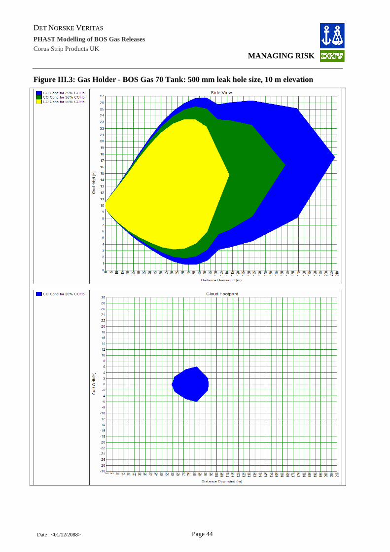
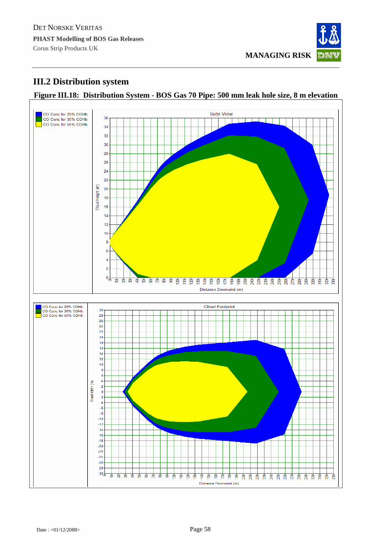
Side views and footprints (at 1.5m height for the scenarios affecting the ground and at the release height for the scenarios not affecting the ground) of the worst case cloud dispersion (as presented in Table 3.4) to the CO concentrations of interest (corresponding to 25%, 35% and 55% COHb in the bloodstream) are presented below for each of the new modelled scenarios.

DET NORSKE VERITAS
PHAST Modelling of BOS Gas Releases
Corus Strip Products UK
MANAGING RISK
Date : <01/12/2088> Page 42
III.1 Gas Holder
Figure III.1: Gas Holder - BOS Gas 70 Tank: 500 mm leak hole size, 1m elevation

DET NORSKE VERITAS
PHAST Modelling of BOS Gas Releases
Corus Strip Products UK
MANAGING RISK
Date : <01/12/2088> Page 43
Figure III.2: Gas Holder - BOS Gas 70 Tank: 500 mm leak hole size, 5 m elevation
DET NORSKE VERITAS
PHAST Modelling of BOS Gas Releases
Corus Strip Products UK
MANAGING RISK
Date : <01/12/2088> Page 44
Figure III.3: Gas Holder - BOS Gas 70 Tank: 500 mm leak hole size, 10 m elevation

DET NORSKE VERITAS
PHAST Modelling of BOS Gas Releases
Corus Strip Products UK
MANAGING RISK
Date : <01/12/2088> Page 45
Figure III.4: Gas Holder - BOS Gas 70 Tank: 500 mm leak hole size, 15 m elevation (No hazard at ground level)

DET NORSKE VERITAS
PHAST Modelling of BOS Gas Releases
Corus Strip Products UK
MANAGING RISK
Date : <01/12/2088> Page 46
Figure III.5: Gas Holder - BOS Gas 40 Tank: 500 mm leak hole size, 1 m elevation

DET NORSKE VERITAS
PHAST Modelling of BOS Gas Releases
Corus Strip Products UK
MANAGING RISK
Date : <01/12/2088> Page 47
Figure III.6: Gas Holder - BOS Gas 40 Tank: 500 mm leak hole size, 5 m elevation

DET NORSKE VERITAS
PHAST Modelling of BOS Gas Releases
Corus Strip Products UK
MANAGING RISK
Date : <01/12/2088> Page 48
Figure III.7: Gas Holder - BOS Gas 40 Tank: 500 mm leak hole size, 10 m elevation

DET NORSKE VERITAS
PHAST Modelling of BOS Gas Releases
Corus Strip Products UK
MANAGING RISK
Date : <01/12/2088> Page 49
Figure III.8: Gas Holder - BOS Gas 40 Tank: 500 mm leak hole size, 15 m elevation (No hazard at ground level)

DET NORSKE VERITAS
PHAST Modelling of BOS Gas Releases
Corus Strip Products UK
MANAGING RISK
Date : <01/12/2088> Page 50
Figure III.9: Gas Holder - BOS Gas 20 Tank: 500 mm leak hole size, 1 m elevation

DET NORSKE VERITAS
PHAST Modelling of BOS Gas Releases
Corus Strip Products UK
MANAGING RISK
Date : <01/12/2088> Page 51
Figure III.10: Gas Holder - BOS Gas 20 Tank: 500 mm leak hole size, 5 m elevation

DET NORSKE VERITAS
PHAST Modelling of BOS Gas Releases
Corus Strip Products UK
MANAGING RISK
Date : <01/12/2088> Page 52
Figure III.11: Gas Holder - BOS Gas 20 Tank: 500 mm leak hole size, 10 m elevation

DET NORSKE VERITAS
PHAST Modelling of BOS Gas Releases
Corus Strip Products UK
MANAGING RISK
Date : <01/12/2088> Page 53
Figure III.12: Gas Holder - BOS Gas 20 Tank: 500 mm leak hole size, 15 m elevation

DET NORSKE VERITAS
PHAST Modelling of BOS Gas Releases
Corus Strip Products UK
MANAGING RISK
Date : <01/12/2088> Page 54
Figure III.13: Outlet Stub - BOS Gas 70: 500 mm leak hole size, 2.2 m elevation

DET NORSKE VERITAS
PHAST Modelling of BOS Gas Releases
Corus Strip Products UK
MANAGING RISK
Date : <01/12/2088> Page 55
Figure III.14: Outlet Stub - BOS Gas 40: 500 mm leak hole size, 2.2 m elevation

DET NORSKE VERITAS
PHAST Modelling of BOS Gas Releases
Corus Strip Products UK
MANAGING RISK
Date : <01/12/2088> Page 56
Figure III.15: Outlet Stub - BOS Gas 20: 500 mm leak hole size, 2.2 m elevation

DET NORSKE VERITAS
PHAST Modelling of BOS Gas Releases
Corus Strip Products UK
MANAGING RISK
Date : <01/12/2088> Page 57
Figure III.16: Open End Vent, 650 mm equivalent diameter, BFG, 52m elevation (No hazard at ground level)
Figure III.17: Open End Vent, 2252 mm equivalent diameter, BFG, 52m elevation (No hazard at ground level)
DET NORSKE VERITAS
PHAST Modelling of BOS Gas Releases
Corus Strip Products UK
MANAGING RISK
Date : <01/12/2088> Page 58
III.2 Distribution system
Figure III.18: Distribution System - BOS Gas 70 Pipe: 500 mm leak hole size, 8 m elevation

DET NORSKE VERITAS
PHAST Modelling of BOS Gas Releases
Corus Strip Products UK
MANAGING RISK
Date : <01/12/2088> Page 59
Figure III.19: Distribution System - BOS Gas 70 Pipe: 500 mm leak, 10 m Elevation

DET NORSKE VERITAS
PHAST Modelling of BOS Gas Releases
Corus Strip Products UK
MANAGING RISK
Date : <01/12/2088> Page 60
Figure III.20: Distribution System - BOS Gas 70 Pipe: 500 mm leak, 16 m elevation

DET NORSKE VERITAS
PHAST Modelling of BOS Gas Releases
Corus Strip Products UK
MANAGING RISK
Date : <01/12/2088> Page 61
Figure III.21: Distribution System - BOS Gas 40 Pipe: 500 mm leak hole size, 8 m elevation

DET NORSKE VERITAS
PHAST Modelling of BOS Gas Releases
Corus Strip Products UK
MANAGING RISK
Date : <01/12/2088> Page 62
Figure III.22: Distribution System - BOS Gas 40 Pipe: 500 mm leak 10 m elevation

DET NORSKE VERITAS
PHAST Modelling of BOS Gas Releases
Corus Strip Products UK
MANAGING RISK
Date : <01/12/2088> Page 63
Figure III.23: Distribution System - BOS Gas 40 Pipe: 500 mm leak, 16 m elevation

DET NORSKE VERITAS
PHAST Modelling of BOS Gas Releases
Corus Strip Products UK
MANAGING RISK
Date : <01/12/2088> Page 64
Figure III.24: Distribution System - BOS Gas 20 Pipe: 500 mm leak hole size, 8 m elevation

DET NORSKE VERITAS
PHAST Modelling of BOS Gas Releases
Corus Strip Products UK
MANAGING RISK
Date : <01/12/2088> Page 65
Figure III.25: Distribution System - BOS Gas 20 Pipe: 500 mm leak, 10 m elevation
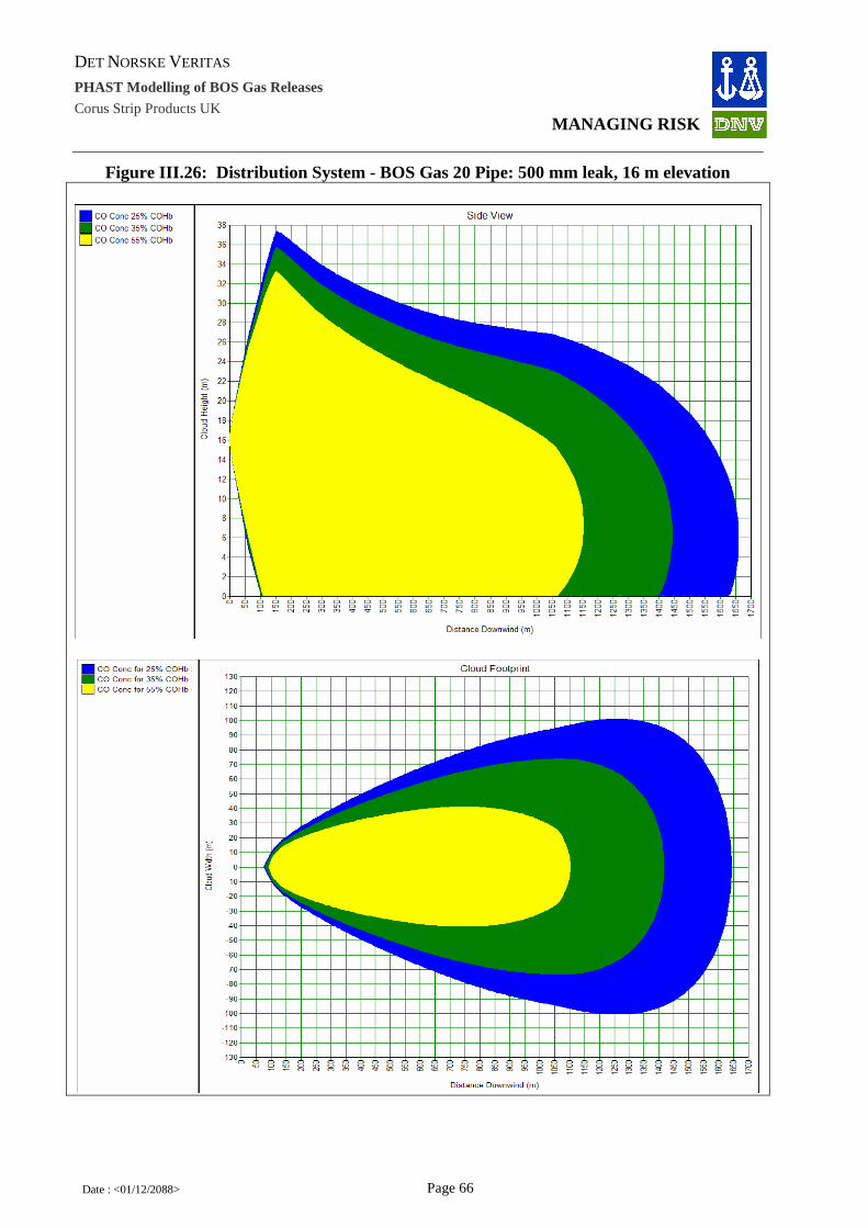
DET NORSKE VERITAS
PHAST Modelling of BOS Gas Releases
Corus Strip Products UK
MANAGING RISK
Date : <01/12/2088> Page 66
Figure III.26: Distribution System - BOS Gas 20 Pipe: 500 mm leak, 16 m elevation

DET NORSKE VERITAS
PHAST Modelling of BOS Gas Releases
Corus Strip Products UK
MANAGING RISK
Date : <01/12/2088> Page 67
Figure III.27: Distribution System - BOS Gas 70 Pipe: 500 mm hole, 8 m elevation, 35 min release

DET NORSKE VERITAS
PHAST Modelling of BOS Gas Releases
Corus Strip Products UK
MANAGING RISK
Date : <01/12/2088> Page 68
Figure III.28: Distribution System - BOS Gas 70 Pipe: 500mm hole, 10 m elevation, 35 min release

DET NORSKE VERITAS
PHAST Modelling of BOS Gas Releases
Corus Strip Products UK
MANAGING RISK
Date : <01/12/2088> Page 69
Figure III.29: Distribution system - BOS Gas 70 Pipe: 500 mm leak hole, 16 m elevation, 35 min release (No hazard at ground level)

DET NORSKE VERITAS
PHAST Modelling of BOS Gas Releases
Corus Strip Products UK
MANAGING RISK
Date : <01/12/2088> Page 70
Figure III.30: Distribution System - BOS Gas 40 Pipe: 500mm hole, 8 m elevation, 35 min release

DET NORSKE VERITAS
PHAST Modelling of BOS Gas Releases
Corus Strip Products UK
MANAGING RISK
Date : <01/12/2088> Page 71
Figure III.31: Distribution System - BOS Gas 40 Pipe: 500 mm hole, 10 m elevation, 35 min release

DET NORSKE VERITAS
PHAST Modelling of BOS Gas Releases
Corus Strip Products UK
MANAGING RISK
Date : <01/12/2088> Page 72
Figure III.32: Distribution System - BOS Gas 40 Pipe: 500 mm hole, 16 m elevation, 35 min release

DET NORSKE VERITAS
PHAST Modelling of BOS Gas Releases
Corus Strip Products UK
MANAGING RISK
Date : <01/12/2088> Page 73
Figure III .33: Distribution System - BOS Gas 20 Pipe: 500 mm hole, 8 m elevation, 35 min release

DET NORSKE VERITAS
PHAST Modelling of BOS Gas Releases
Corus Strip Products UK
MANAGING RISK
Date : <01/12/2088> Page 74
Figure III.34: Distribution System - BOS Gas 20 Pipe: 500 mm hole, 10 m elevation, 35 min release

DET NORSKE VERITAS
PHAST Modelling of BOS Gas Releases
Corus Strip Products UK
MANAGING RISK
Date : <01/12/2088> Page 75
Figure III.35: Distribution System - BOS Gas 20 Pipe: 500 mm hole, 16m elevation, 35 min release

DNV Energy DNV Energy is a leading professional service provider in safeguarding and improving business performance, assisting energy companies along the entire value chain from concept selection through exploration, production, transportation, refining and distribution. Our broad expertise covers Asset Risk & Operations Management, Enterprise Risk Management; IT Risk Management; Offshore Classification; Safety, Health and Environmental Risk Management; Technology Qualification; and Verification. DNV Energy Regional Offices: Americas and West Africa Det Norske Veritas Ltda Rua Sete de Setembro 111/12 Floor 20050006 Rio de Janeiro Brazil Phone: +55 21 2517 7232
Nordic and Eurasia Det Norske Veritas AS Veritasveien 1 N-1322 Hovik Norway Phone: +47 67 57 99 00
Asia and Middle East Det Norske Veritas Sdn Bhd 24th Floor, Menara Weld Jalan Raja Chulan 50200 Kuala Lumpur Phone: +603 2050 2888
Offshore Class and Inspection Det Norske Veritas AS Veritasveien 1 N-1322 Hovik Norway Phone: +47 67 57 99 00
Europe and North Africa Det Norske Veritas Ltd Palace House 3 Cathedral Street London SE1 9DE United Kingdom Phone: +44 20 7357 6080
Cleaner Energy & Utilities Det Norske Veritas AS Veritasveien 1 N-1322 Hovik Norway Phone: +47 67 57 99 00
- o0o -

The Port Talbot Steelworks (Power Generation Enhancement) Order
High Level Assessment of Major Accident Hazards
Appendix 4: Port Talbot Steelworks Safety Report 2013

PORT TALBOT SAFETY REPORT
2013

Introduction This report has been written to satisfy the requirements of the Control of Major Accident Hazards Regulations 1999 as amended and is intended by demonstration and provision of evidence, to confirm the safety and integrity of the activities within the Port Talbot site of Tata Steel UK Limited.
The previous COMAH safety report assessment conclusion was that, while having no serious deficiencies, it did not contain the minimum information and did not make all of the demonstrations required by Schedule 4 of the regulations. Therefore, the company decided to re-write the Safety Report rather than undertaking a revision of the 2008 document. The Port Talbot and Scunthorpe reports are on the same submission cycle and the sites have worked closely together to provide reports that are common in format and, where possible, in content. In addition, the third Tata Steel UK COMAH Tier 1 site, Trostre, has also come into the same cycle and has been involved in the resubmission process. Significant Improvement Activities Since the last safety report submission there have been some significant improvement activities within the Company and Business that have had a positive impact on process safety and COMAH:- Tata Steel Europe (Company Level):-
- The Implementation of a Company Health & Safety Management system - The Implementation of a Group Process Safety Team that sets policy and procedure
on Process Safety - The establishment of a Process Safety Steering Committee chaired by a board
member - The broadening of focus to Losses of Containment and High Potential Near Misses
as well as accident statistics Strip Products UK Hub (Business Level):-
- The Journey Culture change programme that has broken down barriers between management and the workforce and has created a more open environment in which safety is paramount.
- The creation of a Business Process Safety team, providing support and specialist advice to manufacturing, engineering and technical
- The Business Process Safety Roadmap that has driven the PHA programme, MOC implementation, employee awareness and reporting
- The incorporation of the Six Stage Hazard Study process into the Project Management Processes
- The design and ongoing implementation of a Competence Assurance System - The integration of Human Factors into process safety management
Port Talbot Site (Site Level):-
- New benzole storage tanks with associated fire suppression system - Collection and distribution of Basic Oxygen Steelmaking gas (BOS gas) - Redesign and rebuild of Blast Furnace number 4

- UKAS accreditation status for Blast Furnace Pressure systems - Closure of over 300 “red PHA actions” - Improved site security including entry and induction process - Implementation of the ROSOV plan
It should be noted that the last 5 years has been an extremely difficult period for the Company as a whole and the Strip Products UK business due to the global financial recession. The investment in safety through this period demonstrates the company’s commitment to its vision to be a world leader in the steel industry for safety.
Current Organisational Change Programme At time of writing this report, the Strip Products UK Hub, which includes the Port Talbot site, has committed to an organisational change programme to reduce the white collar and administration headcount by 500. This change is necessary for business reasons and the senior management team is committed to ensuring that safety, including process safety, is not negatively affected by the changes. To ensure all safety implications are understood and fully risk assessed, a Management of Organisational Change process is being applied. Report Format & Structure The report is structured in two parts, a general section that covers the Company, Business and Site processes and management systems, and five works area reports that detail the specific hazards and risk controls through detailed discussion of a representative set of scenarios. The general section has been formatted to reflect the Safety Report Assessment Manual (SRAM) Criteria published by the competent authority. The works area reports are structured to give a clear description of the Basis of Process Safety, the detailed demonstration of representative scenarios, and the overall demonstration of ALARP for the works area. The reports are supported with sets of appendices with detailed demonstration and supplementary information. As the report has been restructured and rewritten it has not been possible to indicate the differences to the last report. Many of the report sections are similar and it is intended, by the next submission, that the Company processes are fully aligned so that the majority of the general report is the same for all three sites. For this report, section 10 for Port Talbot and Scunthorpe are identical and section 12 – Process Safety has minor differences only. Representative Set of Scenarios In order to provide detailed demonstration, the site has determined a set of 19 scenarios that represent the different types of hazard and risk controls present, including safety and environmental impacts. The list can be seen below with the unprotected and protected risks. The representative sets for both Port Talbot and Scunthorpe have been aligned to an extent. Differences between the design and installation and also each site’s previous event history have been reflected.
Table A – Port Talbot Representative Set Scenarios

Area Scenario Type of
Event Substance Fatalities Type Unprotected Risk
Protected Risk
1 Energy Catastrophic failure of the BOS gas main
leading to toxic gas release LOC BOS gas >5 S
2 Energy Catastrophic failure of the main leading to
toxic gas release LOC BFG 2-4 S
3 Energy Semi-confined explosion of BFG in boiler due
to failure of valves to seal Explosion BFG/Fuel 1 S
4 Energy Catastrophic failure of 40 barg oxygen
storage vessels or pipe work LOC Oxygen 1 S
5 Energy Oxygen ingress into BOS gas holder leading
to a Vapour Cloud Explosion Explosion BOS gas 2-4 S
6 Raw Materials
Semi-confined explosion in ammonia
incinerator due to BMS failure on start up Explosion COG 1 S
7 Raw Materials
Overfill of benzole storage tank due to
undetected water ingress LOC Benzole 0 E
8 Raw Materials
Catastrohpic failure of benzole storage tank
due to vehicle impact leading to pool fire or
potential VCE
Fire & Explosion Benzole >5 S
9 Raw Materials
Semi-confined explosion in coke battery bus
flue from mechanical failure of reversal winch Explosion BFG 1 S
10 Raw Materials
Semi-confined explosion in COG flarestack Explosion COG 1 S
11 Raw Materials
Failure of bellows leading to release of COG
which then ignites Fire COG 0 S
12 Steelmaking Release of BFG from structural failure of
adjacent equipment damaging the main LOC BFG 2 to 4 S
13 Steelmaking Natural gas leak from flexible hose causing
jet fire LOC & Fire Natural Gas 0 S
14 Ironmaking
Semi-confined explosion of BFG in stoves
mixed gas downleg from air ingress due to
valve failure Explosion BFG 2 - 4 S
15 Ironmaking Molten metal water explosion inside BF4
leading to vessel failure and LOC of BFG Explosion &
LOC BFG 2 - 4 S
16 Ironmaking
Overpressurisation of th BF4 top due to Davy
cone failure in the gas plant leading to
release of BFG LOC BFG 2 - 4 S
17 Mills Semi-confined explosion in reheat furnace
due to BMS failure during start up Explosion COG 1 S
18 Mills Hydrogen explosion from failure to purge
before base batch annealing furnace Explosion Hydrogen 0 S
19 Mills Natural gas jet fire from pipe failure
Jet Fire Natural Gas 1 S
Along with each of the representative set scenarios, the report makes an ALARP demonstration for cumulative risks to an individual and, where applicable, societal risks in each works area section. Improvement Plan

A number of safety report improvement plan items have been identified. These have come from a number of different sources including the predictive process, competent authority interventions, the Company Health & Safety Management System and MAPP audits. Only significant items have been included in the safety report improvement plan. There are other areas of improvement that are ongoing or have been identified in the compilation of this report.
Table B – Port Talbot Improvement Plan Section Improvement Plan Owner Timescale
MAPP & SMS Roll out Process Safety leadership training for senior managers and BMT
S, H & E Manager
By end 2013/14
MAPP & SMS Incorporate Process Safety into Leadsafe programme S, H & E Manager
By end 2014/15
MAPP & SMS Review the Permit to Work System and determine a plan for improvement areas
Engineering Director
Prior to next SR
Predictive Carry out cyclic PHR studies on COMAH plants Manufacturing Director
Prior to next SR
Predictive Complete safeguard registers Manufacturing
Director Prior to next
SR
Predictive Review OBRA procedures and carry out improvements identified
S, H & E Manager
Prior to next SR
Mechanical Continue improvement programme for mechanical integrity for example works arising gas mains and flare stacks
Engineering Director
To plan
Control & Instrumentation
Continue to improve business standards to ensure systems are consistently applied
Engineering Director
Prior to next SR
Human Factors Continue the HF improvement plan S, H & E
Manager Prior to next SR
Emergency Preparedness
Install site wide toxic gas alarm system
S, H & E Manager
By end 2013/14
Ironmaking Install recommended additional layers of protection to stoves gas downleg
Manufacturing Director
Prior to next SR
Energy Review the location of the oxygen storage vessels on central road at the end of their life
Engineering Director
Prior to next SR


Compiled by:- Mal Hill H&S Advisor Lucy James Senior Safety Systems Engineer Mark Thomas Manager, Electrical Engineering Kian Chu Graduate Mechanical Engineer Matthew Jones Principal Engineer, Welding & Metallurgy Joe Cook Human Factors Specialist Richard Leonard Environment Legislation & Compliance Manager Alan Dalgleish Manager, Works Protection Wilfred Richard Process Safety Engineer, Raw Materials Robert Williams-Oyenigba Process Safety Engineer, Ironmaking Anthony Dede-Benefor Process Safety Engineer, Steelmaking Isabel Vazquez Process Safety Engineer, Energy Martin Jones Process Safety Engineer, Mills Ella Woolcock Process Safety Specialist Dave Lewis Process Safety Engineer Malcolm Warren Process Safety Specialist Helen Lewis Process Safety Administration Assistant Marion Davies Process Safety Manager Contributions from:- Works Managers, Works Engineers, Operational Support Managers, Manufacturing Managers, Engineers (mechanical, electrical, process control, process, environment), Technicians, Operators, Human Resources, Group Process Safety & Reprographics. In collaboration with :- Scunthorpe, Trostre, Group Process Safety

Index
Introduction & Summary Main Report Section 9 – Descriptive Section 10 – Predictive Section 11 – MAPP & SMS Section 12 – Process Safety Section 12 – Mechanical Section 12 – Control & Instrumentation Section 12 – Human Factors Section 13 – Environment Section 14 – Emergency Response Works Area Reports Raw Materials Ironmaking Steelmaking Energy Mills

Page 1 of 17
Section 9 Descriptive
Aspects

Descriptive
Page 2 of 17
Document History
No. Revision Date Who 0 February 2013 Submission 12-2-13 M. Davies 1 Document history page added. Duplicate Criteria
9.9, 9.10 and 9.11 relabelled 4-4-13 M. Davies

Descriptive
Page 3 of 17
Criterion 9.1 .................................................................................................................... 4 Criterion 9.2 .................................................................................................................... 4 Criterion 9.3 .................................................................................................................... 6 Criterion 9.4 .................................................................................................................... 7 Criterion 9.5 .................................................................................................................... 7 Criterion 9.6 .................................................................................................................. 10 Criterion 9.7 .................................................................................................................. 15 Criterion 9.8 .................................................................................................................. 16 Criterion 9.9, 9.10 & 9.11 .............................................................................................. 17 Criterion 9.9, 9.10 & 9.11 .............................................................................................. 17

Descriptive
Page 4 of 17
Criterion 9.1
The safety report should give details to allow communication with the competent authority.
Port Talbot Site Address:- Registered Office:- Tata Steel Strip Products UK Tata Steel Europe Limited PO Box 42 Business Headquarters Port Talbot 30 Millbank South Wales London SA13 2NG SW1P 4WY United Kingdom United Kingdom Telephone Exchange: 01639 871111 Telephone: (0207) 7174444 Fax: (0207) 7174455 Registered in England No 05957565
Web-site: www.tatasteeleurope.com
Points of Contact:- Mr Jon Ferriman Business Hub Director Telephone: 01639 87111 Ext2170 Fax: 01639 872020 e-mail: [email protected] Mr Mike Wixey Engineering Director Telephone: 01639 87111 Ext2141 Fax: 01639 872020 e-mail [email protected] Mr Ian Hobson Manufacturing Director Telephone: 01639 871111 Ext2280 Fax: 01639 872020 e-mail: [email protected] Mr. Glenn Perry Health, Safety & Environment Manager Telephone: 01639 871111 Ext 2021 Fax: 01639 872020 e-mail: [email protected] Mrs. Marion Davies Process Safety Manager Telephone: 01639 871111 Ext 2117 Fax: 01639 872020 e-mail: [email protected] Criterion 9.2
The safety report should identify the maximum quantities of every dangerous substance present, or potentially present, on the establishment.

Descriptive
Page 5 of 17
The maximum quantities of dangerous substances held on the TSSPUK Port Talbot site is shown in table 9.2 below. The list was collated based on the guidance provided Schedule 1 Part 2 of the COMAH Regulation or met the criteria laid down in Schedule 1 Part 3 of the same regulation. Each works area section of this report includes the quantities of these substances held in that area.
Table 9.2 – Maximum Inventory of Dangerous Substances
Substance Name Lower Tier Threshold
Upper Tier Threshold
Maximum Site Quantity
Metric Tonnes Schedule 1 Part 2 - Named Substances Hydrogen Hydrogen 5 50 2.7 Oxygen Oxygen 200 2000 126.4 Liquefied Extremely Flammable Gases
Gaseous Natural Gas
50 200
18.6 Propane 8.0
TOTAL LEFG 26.6 Petroleum Products
Gas Oils (including diesel fuels) 2500 25000 661.5
Schedule 1 Part 3 - Categories Toxic Blast Furnace Gas
50 200
230.6 Basic Oxygen Steelmaking Gas 129.3 Benzole 340.0 Coke Oven Gas 54.6 TOTAL Toxic 754.5
Highly Flammable
Benzole 5000 50000 340.0
Extremely Flammable
Coke Oven Gas
10 50
54.6 Blast Furnace Gas 230.6 Basic Oxygen Steelmaking Gas 129.3 TOTAL Extremely Flammable 754.5
Dangerous to the Environment (R51/53)
Benzole
200 500
54.6 Coal Tar 1800.0 BOS Filter Cake (upto 8% ZnO) 80000.0 Heavy Fuel Oil 900.0 TOTAL Dangerous to the Environment 82754.6
The identification of dangerous substance on site is carried out in accordance with the TSSPUK code of practice PSC-03.1 - Identification of High Hazard Facility and High Hazard Installation. (Appendix 1.11). All substances that could give be involved in a MAH are identified, whether or not they are above the lower tier threshold. Where substances have more than one classification they have been counted in both categories. In addition to COMAH substances, this code of practice identifies other dangerous substances that could give rise to major accident hazards. For example, explosive dusts. TSE policy states that we will manage all these hazards to reduce the risks of a MAH to

Descriptive
Page 6 of 17
ALARP as described in TSE Standard HSS-50 (Appendix 1.1). Non-COMAH dangerous substances are not discussed further in this report unless they could initiate a COMAH major accident.
Molten metal and slag are dangerous substances specific to this industry. Other than personal safety hazards, the main hazard of handling these materials are reaction with water causing a molten metal water explosion. There is a potential for a molten metal water explosion to be the initiating event for a COMAH major accident scenario and this is included in the Ironmaking Works Area Safety Report. Handling and transport of molten metal is not considered to give rise to a COMAH major accident hazard, as any such credible molten metal water explosion is too remote from COMAH inventory and/or controls. Blast Furnace Gas is an anomaly. Following the classification process it is “Extremely Flammable”. However, BFG is a very low heating value fuel, containing inerts of approximately 58% nitrogen and 17% carbon dioxide. Therefore, the gas is only likely to support stable combustion at elevated temperatures, or with a permanent pilot flame. Site experience suggests that BFG may be ignited by a high ignition source such as a welding torch. However, the resulting combustion is slow and lazy. BFG is not typically considered an explosion hazard for the same reasons. Criterion 9.3
For each dangerous substance identified, the safety report should describe its chemical name (including common use chemical name) and CAS number according to IUPAC nomenclature. The chemical names and CAS numbers for the dangerous substances are illustrated in table 9.3.
Table 9.3 – Dangerous Substance Information
IUPAC Nomenclature Name Composition CAS Number
Hydrogen Hydrogen 100% Hydrogen 1333-74-0 Oxygen Oxygen 100% Oxygen 7782-44-7 Natural Gas Natural Gas 86-94% Methane
2-8% Ethane 0-8% Nitrogen 0.5-3% Propane 0-2.2% Carbon Dioxide
74-82-8 74-84-0 7727-37-9 74-98-6 124-38-9
Propane Propane >99% Propane 74-98-6 Diesel Gas Oil, Diesel Complex mixture of middle
distillate hydrocarbons C10 to C28 68334-30-5
Blast Furnace Gas BFG 40-60% Nitrogen 20-25% Carbon Monoxide 15-30% Carbon Dioxide 1-8% Hydrogen
65996-68-1

Descriptive
Page 7 of 17
Basic Oxygen Steelmaking Gas
BOS Gas 50-80% Carbon Monoxide 10-20% Carbon Dioxide 8-30% Nitrogen 0.5-2.5% Hydrogen 01-0.5% Oxygen
65996-68-1
Crude Benzole Benzole 68-80% Benzene 10-20% Toluene 2-5% Xylene 3-5% Napthalene <0.2% Hydrogen Sulphide <1% Hydrogen cyanide
65996-78-3
Coke Oven Gas COG 62-66% Hydrogen 21-25% Methane 5-7% Carbon Monoxide 1-5% Nitrogen
65996-81-8
Crude Coal Tar
Coal Tar
Complex mixture of mainly aromatic and polyaromatic hydrocarbons and heterocyclic hydrocarbons, including about 15% naphthalene.
65996-89-6
BOS Gas Cleaning Solids
BOS Filter Cake
60-70% Iron 0.5-2.5% Silicon 1-3% Zinc 2-5% Calcium
NA
Heavy Fuel Oil Heavy Fuel Oil Mixture 68476-33-5 Criterion 9.4
The safety report should describe the physical and chemical behaviour of each dangerous substance identified, relevant to normal operating conditions and foreseeable accident conditions. MSDS sheets for the dangerous substances are attached in appendix 4 and can be found using the links in table 9.3 above. The works area sections of the report detail the specific operating conditions and dangerous substances in that area. Criterion 9.5
The safety report should describe the immediate and delayed harm to man and the environment for each dangerous substance identified. The table below summarises the potential harm from each dangerous substance.

Descriptive
Page 8 of 17
Table 9.5 – Harm Potential of Dangerous Substances
Name Impact Immediate Harm
Delayed Harm Health Effect Lethal Concentration
Fire and Explosion Harm Environmental Effect Route(s) to Harm
Hydrogen People Buildings
VCE Flash fire Jet-fire
None Harmful by inhalation. Asphyxiant
N/A Extremely flammable.
Explosive air/vapour mixtures may form at ambient temperature
None Air
Oxygen People Buildings
Jet-fire None None N/A Strongly supports combustion. May react violently with combustible materials.
N/A Air
Natural Gas People Buildings
VCE Flash fire
None Harmful by inhalation. Asphyxiant
N/A Extremely flammable. Explosive air/vapour mixtures may form at ambient temperature
None Air
Propane People Buildings
Vapour Cloud Explosion
None Harmful by inhalation. Asphyxiant
N/A Extremely flammable.
Explosive air/vapour mixtures may form at ambient temperature
None Air
Gas Oil Environment Physical damage Long term impact Toxic to aquatic organisms. Some constituents may bio-accumulate
Ground
BFG People Buildings
Semi-confined explosion Toxic
None Toxic Rapidly fatal if >20,000 ppm as COG (>5,000 ppm as CO)
Semi-confined explosion. None Air
BOS Gas People Buildings
VCE Semi-confined explosion Jet-fire Toxic
None Toxic Rapidly fatal if >8,000 ppm as COG (>5,000 ppm as CO)
Extremely flammable. Vapour may form an explosive mixture with air. Jet fire.
None Air

Descriptive
Page 9 of 17
Name Impact Immediate Harm
Delayed Harm Health Effect Lethal Concentration
Fire and Explosion Harm Environmental Effect Route(s) to Harm
Benzole People Buildings Environment
VCE Pool fire Toxic
Minor components may cause delayed harm to aquatic organisms. Carcinogenic
Toxic and carcinogenic
1,000 ppm Highly volatile and flammable. Vapour may form an explosive mixture with air.
Toxic to fish. Vapour, ground.
COG People Buildings
Semi-confined explosion Toxic
None Toxic Rapidly fatal if >80,000 ppm as COG (>5,000 ppm as CO)
Semi-confined explosion. Jet fire.
None Air
Coal Tar Environment Toxic to aquatic organisms. May cause long-term adverse effects to the aquatic environment.
Irritant. Carcinogenic if prolonged contact or exposure. Possible harm to unborn children.
N/A Combustible (flammable if dry). Toxic to aquatic organisms, may cause long-term adverse effects to the aquatic environment.
Vapour, ground.
BOS Filter Cake
Environment R50/53- Very toxic to aquatic organisms. May cause long term adverse effects in the aquatic environment.
Irritant due to lime content (alkali). Fume hazard at elevated temperatures.
N/A N/A R50/53- Very toxic to aquatic organisms, may cause long term adverse effects in the aquatic environment
Ground
Heavy Fuel Oil
People Environment
VCE Long or repeated skin contact may irritate the skin and may cause formation of cancer tumours
Vapours may irritate eyes and respiratory system. High doses may cause nausea and headaches.
N/A Combustible. Vapours may form explosive mixtures with air.
Harmful to aquatic organisms, may cause long-term adverse effects in the aquatic environment. Release of the product into water will result in a film of hydrocarbons floating on the surface. Due to low water solubility the predominant loss is through volatilisation. Molecules with higher molecular weight will be absorbed on sediment. Has the potential to bio-accumulate.

Descriptive
Page 10 of 17
The harm criteria for the dangerous substances relevant to Tata Steel, including Toxic Effects, Thermal Radiation Effects and Overpressure Effects are detailed in PSG-04.1.13 Harm Criteria for modelling, Appendix 1.6. Criterion 9.6
The safety report should describe the environment of the establishment in sufficient detail to allow the consequences of major accidents to be assessed. General
Port Talbot Establishment is situated South-East of Swansea. The site boundary is defined in Map 10 (Appendix 3.11). Map 12 (Appendix 3.13) shows the Establishment layout, together with the immediate surroundings indicating the Industrial Areas, Agricultural Areas, Urban Settlements, Schools, Listed Buildings, Motorway, Railway network, Harbours, Scheduled Ancient Monuments (SAM) and Environmentally Sensitive Sites (SSSI’s – Site of Special Scientific Interest). Access to and from the Establishment is via one of two Security Gatehouses located at O/S Co-ordinates: - MAIN ACCESS 277732E 187629N WEST END ACCESS 277169E 188560N These are shown on Map 1 Appendix 3.1. Significant traffic routes for rescue and emergency operation are the two main roads adjacent to the Establishment, i.e. the A48 and M4 Motorway shown on Map 12. It should be noted, however, that the new Port Talbot Distributor Road (PDR) will also provide a route for emergency access from the autumn of 2013. The Surrounding Population Adjacent to the Port Talbot Establishment are the wards of Port Talbot, Taibach, Margam, Aberafan and Sandfields East. The population of each ward based on the 2011 census is: - Port Talbot - 5276 Taibach - 4582 Margam - 2389 Aberafan - 5336 Sandfields East - 6117 The Surrounding Environment The wards are shown on Map 12. The only hazard with an off-site impact is the release of Basic Oxygen Steelmaking gas that contains up to 80% carbon monoxide. Dispersion modelling has been carried out to determine the potential harm outside the Establishment. This indicates that the only ward that potentially could be affected is Taibach. The Energy Installation report contains more details on this. To the north of the Establishment is an area allocated for light industrial use surrounding an operational dock. Parts of this area were sold to the Welsh Development Agency (WDA) in 1999. Associated British Ports (ABP) and DWR Cymru operate plant adjacent to the Establishment and access to these plants is via the Tata Establishment roadways. These areas are shown

Descriptive
Page 11 of 17
on Map 10. The only area likely to be affected by a major incident is the old Dock owned by ABP. Meteorological Data Historical local weather data has been obtained from the Meteorological Office in Exeter. The wind direction and speed data (wind rose format) in Appendix 9.2 is based on readings taken at the weather station at Mumbles Head, Swansea, which is located 6 miles due west of the Port Talbot Site, in the period January 2003 to December 2012. The current readings are in the same order of magnitude as those obtained for the period 2002-2006 used in the Port Talbot 2008 re-submitted safety report and show that the prevailing wind direction comes from a Westerly/ South Westerly direction. The data given in Appendix 9.2 was measured at the same weather station in the same period (January 2003 to December 2012) and summarises the Pasquill stability classes. For the purposes of dispersion modelling and based on the data contained in Appendix 9.2, the conditions used were: Pasquill Class F at a wind speed of 2 m/s (3.8 knots) and Pasquill Class D at a wind speed of 5 m/s (9.7 knots). Further details of PHAST Modelling criteria and justification for its use are given in the Predictive section 10.5 of this report Lightning Hazard Munich RE has provided the hazard report of the area around Swansea in the UK. The whole area, including the territory of TATA Port Talbot Steel Works, lies in the zone of low frequency of lighting strikes (less than 2 per km2 and less than 2 per year). This is illustrated in the following map.

Descriptive
Page 12 of 17
Geological and Hydrological Data Port Talbot Establishment is entirely underlain by Coal Measures, which dip gently northwards. The northern part of the works overlies the lowest beds of the Upper Coal Measures, the central part is on the Middle coal measures, and the southern part is on Lower Coal Measures. The surface of the bedrock dips steeply towards Swansea Bay and the sand and gravel drift is commonly 20 m deep. Much of the Establishment has been built up with slag, especially along the coast and at the Old River estuary area. The beach is mainly sandy, but there are several outcrops of clay. A copy of the BGS Map (Sheet 247) is kept at the Tata Swinden Technology Centre. A geological cross-section is shown in Appendix 9.1. All major buildings and structures are built on appropriately designed piled reinforced concrete foundations. Designs are based on the ground condition as determined from boreholes. Ground Water

Descriptive
Page 13 of 17
Two groundwater bodies underlie the Establishment. The upper unconfined aquifer is the blown sand that blankets the Establishment, whilst the lower, confined aquifer is the estuarine sands underlying an impervious clay layer. There are no drinking water abstraction points on the Establishment. The only known abstraction point in the vicinity is at Kenfig Industrial Estate (SS797.834) approximately 1 km south east of the Establishment boundary shown on Map 12. Pumping tests show a high potential yield in the glacial sands and gravels, and a licence is held for abstraction for industrial use, but is not currently used. The EA monitor groundwater levels at Kenfig Pool, to the south. Surface Water Of the surface waters within the Establishment’s vicinity, the Rivers Kenfig, Afan and Frwdwyllt have been given river water quality targets by the Environment Agency. All three rivers are graded A or B for chemical water quality, dependent on the stretch of river. Compliance with targets is very good. There is no water quality classification for the aquifers on the Establishment. All surface drainage water including fire-fighting water arising within the Establishment is collected by the Works effluent system. To the north end of the Establishment, this is primarily to Margam No 1 Sump. Surface drainage from the south end of the Establishment is primarily captured by the deep drain system. Other areas of the Establishment, e.g. BOS Plant and Coke Ovens, have local sumps that collect surface drainage water. All of the sumps are integrated within the Establishment effluent system. There are drying lagoons on the Establishment for the Blast Furnace and BOS slurry. The run off water from these goes into the local sumps and then into No 2 sump, before discharge to sea. The responsibility for these lagoons lies with the Blast Furnace and Steelmaking and Concast Installations.
All discharges, with the exception of sewage and iron ore stockyards, leave the Establishment via No 2 sump to the long sea outfall. No 3 sump has a weir, which if breached, would allow effluent to discharge via the Abbey Beach Outfall. All of the sumps and discharge points are shown on Map 8 (Appendix 3.9).
These are not considered to be vulnerable to the effects of a major accident.
The Built Environment A number of Listed Buildings and Ancient Monuments surround the Port Talbot Establishment. These are not considered to be vulnerable to the effects of a major accident. The adjacent Transport and Utilities that may be vulnerable to the effects of a Major Accident are:-
• The Main Railway Line (Paddington to Fishguard).
• The new Peripheral Distribution Road (PDR)
The position of the railway line relative to the site is shown on Map 1 (Appendix 3.1).
For the main Paddington to Fishguard railway line, approximately ten trains per hour pass the Establishment. Normal train speed is in the range 60 to 80 mph with no planned stops in the section of railway line adjacent to the Establishment. In the event of a major release of BOS gas passengers and crew onboard the trains would not be exposed to harmful levels of CO

Descriptive
Page 14 of 17
long enough to be affected, assuming the slowest speed and that the train itself does not give any protection from the outside environment. The PDR is the largest transport project for Wales since the creation of the M4. It will provide a 4.8 km link to the motorway at Junction 38 (Margam) into Port Talbot and the Docks. Work started in January 2011 and is due to be completed in the autumn of 2013. The route of the PDR (shown on Map 1) passes through land that was previously owned by Tata Steel and that was subject to a Compulsory Purchase Order. The PDR will change the main entrance into site and therefore the visitor centre and security gates will be relocated. The new road also goes through the existing main site stores so a new store building and a new apprentice training centre are being built adjacent to the new entrance. With the exception of the visitor centre, the new buildings are further from the site major accident hazards. Toxic Gas Refuges have been incorporated into the design of the new buildings. Consideration has been made to the public traffic on the road. As with the railway line, any exposure will be transient and being in a vehicle will offer a degree of protection. Consideration was made to positioning traffic lights either side of the site that could be used to stop traffic in the event of an emergency. On balance, it was decided that this would not be proportionate and may lead to build-up of traffic that was then vulnerable if the wind direction changed. The off-site plan will be amended before the new road is opened to the public to address the emergency action required by the emergency authorities.
The Natural Environment Port Talbot Establishment has, in its near vicinity, and on its own land, areas of significant environmental importance – protected sites of local, national and European importance. The sites are shown on Map 12 (Appendix 3.13) and the reasons for their importance are summarised below.
Eglwys Nunydd Reservoir, built for the steelworks and owned and maintained by Tata is, at 225 acres in size, the largest sheet of fresh water in the county. It is located on the old site of Margam Moors, which, prior to being reclaimed for the building of the works, was itself a notable site for wildfowl. The reservoir is now important for the large numbers of wintering waterfowl and passage migrants it attracts. Notable species including Great Crested and Little Grebes, Mallard, Gadwall and Coot now breed here.
Margam Moors is the last remaining example of the once extensive coastal levels in West Glamorgan. Bounded to the seaward by dunes, and to the landward by high ground, the meadows provide an agriculturally managed freshwater habitat, which hosts many species of plant on the edge of their geographical range, and nationally important invertebrates. Mesotrophic marsh, fen meadows and ditch communities support Flowering-rush, Frogbit, Arrowhead, Cyperus Sedge and Brown Sedge on the edge of their range, with others such as Lesser Water-plantain, Tubular Water-dropwort and Marsh Helleborine of local interest. The nationally rare beetle, Haliplus Mucronatus, the dragonfly Sympetrum Sanguineum, the regionally rare beetle Anacaena Bipustulata, and the water bug Corixa Panzeri have all been found in the ditches.
Kenfig Pool and Dunes. This large dune system is noted by botanists for its large slacks supporting many fen plants including the very rare Liparis Loeselii (fen orchid). Kenfig Pool, the largest freshwater lake in Glamorgan, has good aquatic zonation and supports numerous wildfowl in winter. Only the careful management of the recreational, educational and other competing claims upon the pool and dunes will retain the special scientific interest of this site. Within a European context, the area is of priority because of its dune grasslands, dune with creeping willow, humid dune slacks, because it contains over 40% of the known UK

Descriptive
Page 15 of 17
population of fen orchid, and because it is an important site for petalwort. Kenfig SSSI was designated a SAC (Special Area of Conservation) in 2004.
Swansea Bay, to the west of the Works, is a designated shellfish bed. Criterion 9.7
The safety report should describe the environment of the establishment in sufficient detail to allow the contribution of external factors to major accidents at the establishment to be assessed. Although deep coal mining is known to have taken place beneath the Establishment, there are no records of any problems having been encountered with ground stability as a consequence of these activities. A feasibility study for an excavation to mine coking coal is being conducted at the Port Talbot site. The Margam Mine infrastructure would be located on a ring-fenced site on the Port Talbot site and access shafts would run beneath the site to the coal measures which are several km off-site in a SE direction. If the company decides to proceed it will consult with the CA and write a COMAH modification report. In the event that the project goes ahead, the first coal is planned to be extracted in 2018. British Geological Survey (BGS) data listing the “Larger British Earthquakes in the 20th Century”, included in the 2002 Safety Report, (i.e. those having a magnitude greater than 4.5 ML) shows no record of any significant seismic events affecting this Establishment. A flood risk assessment has been performed for Port Talbot site, using data obtained from the Environment Agency. The assessment shows that there is no risk of a COMAH major accident arising from foreseeable flood events. See appendices 9.3 and 9.4. Air traffic is a potential risk to the site, albeit very low. The following airfields have been identified and their distances from the nearest Port Talbot boundary established:-
Cardiff International airport – greater than 20 miles. RAF St. Athan – greater than 20 miles. Swansea Airport – 8 Miles.
Port Talbot is greater than 40 kilometres away from the Mid Wales Military Training Area (MTA) that carries an enhanced risk and is greater than 40km from the Area of Intense Aircraft Activity (AIAA) in the mid Somerset area. Port Talbot is in the centre of a Military Avoidance Area. The conclusion is that the risk from military aircraft is low. One area that is specific and local to the Port Talbot site is the question of elective helicopter flights to and around the site. Two categories are relevant. Firstly, the use of air ambulances in the event of a serious accident on site and secondly the electricity distribution line monitoring carried out by the electricity transmission company. Since 2008, the security of the site has improved significantly with the implementation of security gates and access control. The Works Protection department are on site 24/7 and carry out patrols and inspections on a frequent basis. There are no radio transmission masts in the area that could impact safety control systems or communications.

Descriptive
Page 16 of 17
Criterion 9.8
The safety report should give an overview of the establishment, particularly identifying those relevant to Major Accident Hazards. The overall geography of the Establishment, including some key features such as major installations, location of hazardous substances, points of access, road and rail routes and drainage systems are given in the following maps and diagrams: Map 1 (Appendix 3.1)
• Main access/egress points via Security Gatehouses. Roadways (GREEN) that would be the access and egress routes in the event of a major emergency.
• Railway lines (BLUE). • Raw materials stocking area (RED).
Map 2 (Appendix 3.2)
• Major installations. • Installations with major Hazard Potential. • Location of gas vents.
Map 2.1 (Appendix 3.3)
• COMAH Hazardous Substances storage locations. • Establishment Ancillary Systems. • Stores locations.
Map 3 (Appendix 3.4) COG Spinal Main Map 4 (Appendix 3.5) BFG Spinal Main. Map 5 (Appendix 3.6) Industrial Water Supplies. Map 6 (Appendix 3.7) Natural Gas Spinal Main. Map 7 (Appendix 3.8) Basic Oxygen Steelmaking Gas Spinal Main. Map 8 (Appendix 3.9) Establishment drainage system including monitoring stations, and effluent treatment Installations. Map 9 (Appendix 3.10) Location of hydrant mains Map 11 (Appendix 3.12) Oxygen Gas Spinal Main. Map 14 (Appendix 3.13)Map of the consultation zone at Port Talbot site.
Figure 9.8 - Port Talbot Works Area Relationships
Raw Materials
Iron Making
Steel Making
Rolling Mills
Energy

Descriptive
Page 17 of 17
Criteria 9.9, 9.10 & 9.11
These sections require detailed information on processes, scenarios and measures in place with regard to major accident hazards. These are addressed in the Works Area Safety Reports. Criteria 9.12 & 9.13
These sections do not require a response since the Port Talbot site is not part of a domino group and no other organisations were involved in creating this safety report.

Section 10 Predictive Aspects
Criterion 10.1

Predictive
Page 2 of 11
The safety report should clearly describe how the operator uses risk assessment to help make decisions about the measures necessary to prevent major accidents and to mitigate their consequences. Tata Steel Europe (TSE) has a standard for Process Safety Risk Management HSS-50 (Appendix 1.1). This standard gives specific requirements for the management of High Hazard Facilities within the organization to ensure compliance with the Tata Steel Health & Safety Management system and to ensure that Major Accident Risks are reduced to As Low As Reasonably Practicable (ALARP). The application of HSS-50 is broader than the requirements of COMAH because it endeavors to identify all major accident risks within the company, for example water/molten metal explosions and coal powder explosions. However, these risks are not covered in this safety report, which deals solely with COMAH, unless they form initiating events for a COMAH major accident scenario. TSE Code of Practice PSC-03.2 “Process Hazard Analysis (PHA) in High Hazard Facilities” (Appendix 1.2) describes the generic methodology used to identify, assess and mitigate or eliminate process safety risks both on a cyclic basis for existing assets and during the design process for new or modified installations.
Figure 10.1 – Two Pyramid Model

Predictive
Page 3 of 11
For the UK COMAH sites a more detailed process flow has been created to specify the steps required to ensure that major accident hazards are identified and reduced to ALARP.
Figure 10.2 – UK COMAH Process
Criterion 10.1.1 It should be clear that human factors have been taken into account in the risk analysis. The structured PHA methodology used in TSE is designed to identify all causative mechanisms of major accident hazards including human failure. Once a MAH has been identified that is either caused by human failure, or has a layer of protection that relies on a procedure or human interaction, then Human Failure Analysis is applied. TSE guidance PSG-10.0.50 “Human Factors in Process Safety Risk Management” (Appendix 1.29) defines the requirement and PSG-10.0.52 “Human Failure Analysis in PSRM” (Appendix 1.31) provides guidance on how to apply it.
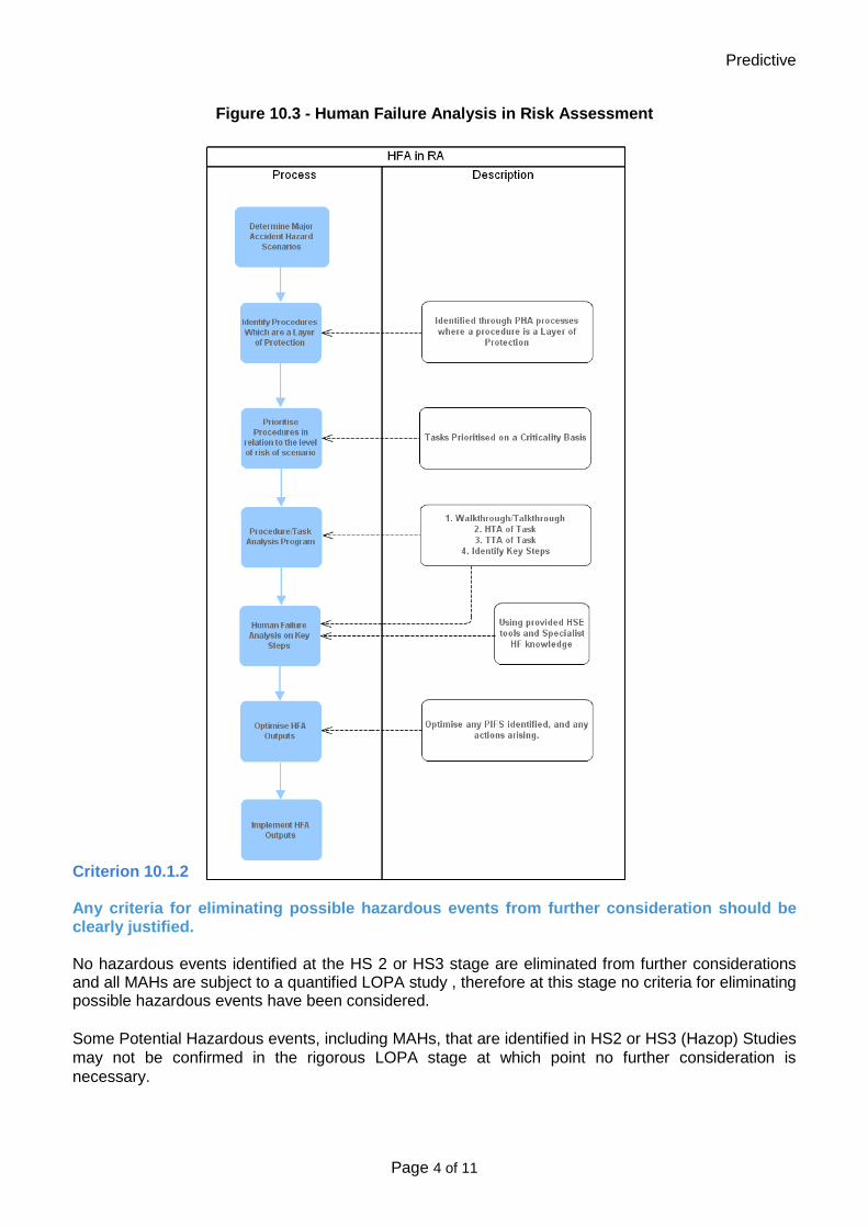
Predictive
Page 4 of 11
Figure 10.3 - Human Failure Analysis in Risk Assessment Criterion 10.1.2 Any criteria for eliminating possible hazardous events from further consideration should be clearly justified. No hazardous events identified at the HS 2 or HS3 stage are eliminated from further considerations and all MAHs are subject to a quantified LOPA study , therefore at this stage no criteria for eliminating possible hazardous events have been considered. Some Potential Hazardous events, including MAHs, that are identified in HS2 or HS3 (Hazop) Studies may not be confirmed in the rigorous LOPA stage at which point no further consideration is necessary.

Predictive
Page 5 of 11
Criterion 10.2 The safety report should demonstrate that the operator has used information and data that are suitable and sufficient for risk analysis. Criterion 9.6 describes the appropriate meteorological conditions for the site based on recent data and the current description of the general environment including off-site populations and surrounding environmental features. TSE guidance document PSG-04.1.13 “Harm Criteria for Modelling” (Appendix 1.6) specifies the harm criteria and consequence modelling criteria for toxic, thermal and pressure effects including stability/wind speed conditions. Criterion 10.3 The safety report should identify all potential major accidents and define a representative and sufficient set for the purpose of risk analysis. The PHA process as described in PSC-03.2 (Appendix 1.2) has been used to identify all major accidents in TSE. Again TSE has published guidance on the selection of representative sets following the HSE guidance for COMAH sites in PSG-04.1.12 “Selection of a representative set of major accident scenarios for detailed description in the site safety report to the competent authority” (Appendix 1.5). Criterion 10.3.1 The safety report should demonstrate that a systematic process has been used to identify all foreseeable major accidents. PSC-03.2 “Process Hazard Analysis in High Hazard Facilities” (Appendix 1.2) describes the key steps of PHA. Figure 10.4 is an excerpt from PSC03.2 which gives an overview of the process

Predictive
Page 6 of 11
Criterion 10.3.2 The hazard identification methods used should be appropriate for the scale and nature of the hazards. PSC-03.3 “Policy on PHA Methodologies” (Appendix 1.7) determines the overall approach to hazard studies and gives guidance on the level of study that should be used. As a minimum, businesses are required to carry out PHR2 to identify major accidents. This methodology is described in detail in PSG-03.2.52 Process Hazard Review Stage 2 (Appendix 1.8). In some business units, a decision has been made to apply level 3 process safety studies e.g. Hazard and Operability Studies (HAZOP) to more complex processes. This traditional technique has been extended to include a qualitative risk assessment in addition to hazard identification. The methodology is described in PSG-03.2.53 “How to do Process Hazard Identification and Risk Assessment” (Appendix 1.3). Criterion 10.4 The safety report should contain estimates of the probability (qualitative or quantitative) of each major accident scenario or the conditions under which they occur, including a summary of the initiating events and event sequences (internal or external), which may play a role in triggering each scenario. All PHA methodologies in TSE require a qualitative assessment of where the hazard lies on the TSE risk grid PSC-03.2.10 “Process Safety Risk Tolerability Grid” (Appendix 1.9) after safeguards i.e protected (residual) risk. For COMAH sites, an assessment of risk before safeguards, i.e. unprotected (inherent risk) is also undertaken. The qualitative assessment is the judgement of the hazard study team on the potential severity and the probability of the scenario based on experience and historical plant knowledge. This qualitative assessment is then used as a filter for determining if a further semi-quantitative assessment is required. Different approaches have been taken in different businesses depending on the culture of the business. In Port Talbot and Trostre, the filter is purely severity i.e. any scenario involving fatalities (single or more) or any scenario causing a MATTE is then analysed further using Layer of Protection Analysis (LOPA). In Scunthorpe, the filter is based on residual risk for major accident scenarios i.e. risks deemed to be in the borderline of tolerability. Both approaches are equally valid. TSE guidance document PSG-03.2.56 “LOPA Methodology for ALARP Demonstration” (Appendix 1.4) defines the LOPA process and gives guidelines on selecting and deriving failure rate values. TSE guidance document PSG-04.1.12 “Selection of a representative sets” (Appendix 1.5) gives the definition of a safety critical event and process for selecting them.

Predictive
Page 7 of 11
Figure 10.5 - TSE Process Safety Risk Grid
Criterion 10.4.1 The safety report should demonstrate that a systematic process has been used to identify events and event combinations which could cause major accident hazards to be realized. The PHA methodologies used in TSE to identify major accidents also identifies the events and event combinations that cause them. PSC-03.2 “Process Hazard Analysis in High Hazard Facilities” (Appendix 1.2) describes the key steps of PHA which are illustrated in the flowchart in criterion 10.3.1. Criterion 10.4.2 All safety critical events and the associated initiators should be clearly identified TSE document PSG-04.1.12 “Selection of a representative sets” (Appendix 1.5) defines the process for selecting the representative set. For each representative set scenario a LOPA study has been undertaken to semi-quantitatively determine the residual risk. The residual risk is then compared to the risk tolerability criteria. For risks in the tolerable if ALARP region, a cost benefit analysis is carried out to determine if the cost of applying the identified control measure is proportionate to the risk reduction.

Predictive
Page 8 of 11
TSE document PSG-06.0.04 “ALARP Determination for PS risk in high hazard facilities” (Appendix 1.10) gives guidance on the CBA methodology. A spreadsheet tool has been developed based on this. See appendix 1.16 – LOPA/CBA spreadsheet. Risk tolerability criteria have been determined for single fatality scenarios, but these tolerability criteria cannot be used for multiple fatalities. For scenarios causing more than one fatality the CBA approach is applied first to determine if the risk is ALARP for a single fatality and then an ARI(COMAH) calculation is carried out to determine the societal risk tolerability. Criterion 10.4.3 Estimates of, or assumptions made about the reliability of protective systems and the times for operators to respond and isolate loss-of-containment accidents etc, need to be realistic and adequately justified. Guidance document PSG-03.2.56 “LOPA for ALARP Demonstration” (Appendix 1.4) defines the LOPA process and gives guidelines on selecting and deriving failure rate values. The works area reports give specific details and justify the reliability of protective systems and operator response. Criterion 10.4.4 The methods used to generate event sequence and estimates of the probabilities of potential major accidents should be appropriate and have been used correctly. Guidance document PSG-03.2.56 “LOPA for ALARP Demonstration” (Appendix 1.4) defines the LOPA process and gives guidelines on selecting and deriving failure rate values. Criterion 10.4.5 The safety report should provide adequate justification for event probabilities that are not consistent with historical or relevant generic industry data. Historical and anecdotal evidence from the site are used predominantly to determine probabilities and failure rates. Any non-site data used that gives a probability of failure on demand of less than 1 in 10 is justified in the LOPA and referenced to the source data. Criterion 10.5 The safety report should provide details to demonstrate that suitable and sufficient consequence assessment for each major accident scenario has been carried out with respect to people and the environment. There are number of different major accident scenarios within TSE. The consequences of the different scenarios have been determined using the following techniques Modelling Method Toxic cloud dispersion PHAST Jet Fires PHAST Flash Fires PHAST Pool Fires PHAST
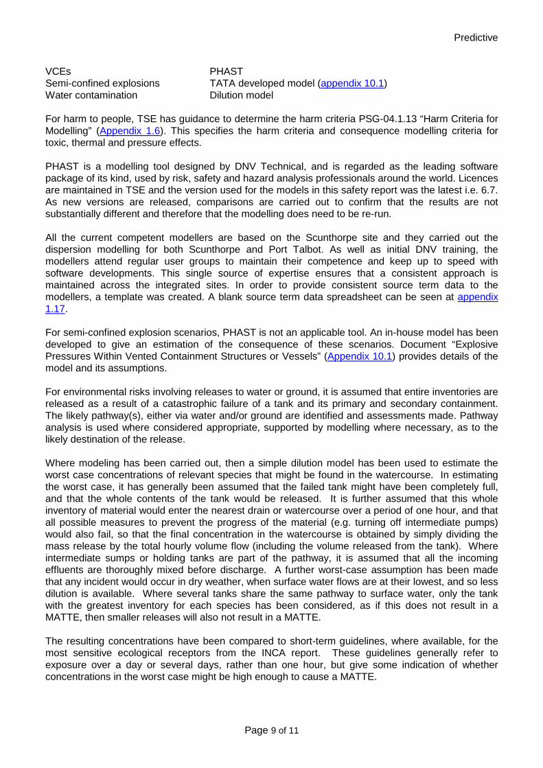
Predictive
Page 9 of 11
VCEs PHAST Semi-confined explosions TATA developed model (appendix 10.1) Water contamination Dilution model For harm to people, TSE has guidance to determine the harm criteria PSG-04.1.13 “Harm Criteria for Modelling” (Appendix 1.6). This specifies the harm criteria and consequence modelling criteria for toxic, thermal and pressure effects. PHAST is a modelling tool designed by DNV Technical, and is regarded as the leading software package of its kind, used by risk, safety and hazard analysis professionals around the world. Licences are maintained in TSE and the version used for the models in this safety report was the latest i.e. 6.7. As new versions are released, comparisons are carried out to confirm that the results are not substantially different and therefore that the modelling does need to be re-run. All the current competent modellers are based on the Scunthorpe site and they carried out the dispersion modelling for both Scunthorpe and Port Talbot. As well as initial DNV training, the modellers attend regular user groups to maintain their competence and keep up to speed with software developments. This single source of expertise ensures that a consistent approach is maintained across the integrated sites. In order to provide consistent source term data to the modellers, a template was created. A blank source term data spreadsheet can be seen at appendix 1.17. For semi-confined explosion scenarios, PHAST is not an applicable tool. An in-house model has been developed to give an estimation of the consequence of these scenarios. Document “Explosive Pressures Within Vented Containment Structures or Vessels” (Appendix 10.1) provides details of the model and its assumptions. For environmental risks involving releases to water or ground, it is assumed that entire inventories are released as a result of a catastrophic failure of a tank and its primary and secondary containment. The likely pathway(s), either via water and/or ground are identified and assessments made. Pathway analysis is used where considered appropriate, supported by modelling where necessary, as to the likely destination of the release. Where modeling has been carried out, then a simple dilution model has been used to estimate the worst case concentrations of relevant species that might be found in the watercourse. In estimating the worst case, it has generally been assumed that the failed tank might have been completely full, and that the whole contents of the tank would be released. It is further assumed that this whole inventory of material would enter the nearest drain or watercourse over a period of one hour, and that all possible measures to prevent the progress of the material (e.g. turning off intermediate pumps) would also fail, so that the final concentration in the watercourse is obtained by simply dividing the mass release by the total hourly volume flow (including the volume released from the tank). Where intermediate sumps or holding tanks are part of the pathway, it is assumed that all the incoming effluents are thoroughly mixed before discharge. A further worst-case assumption has been made that any incident would occur in dry weather, when surface water flows are at their lowest, and so less dilution is available. Where several tanks share the same pathway to surface water, only the tank with the greatest inventory for each species has been considered, as if this does not result in a MATTE, then smaller releases will also not result in a MATTE. The resulting concentrations have been compared to short-term guidelines, where available, for the most sensitive ecological receptors from the INCA report. These guidelines generally refer to exposure over a day or several days, rather than one hour, but give some indication of whether concentrations in the worst case might be high enough to cause a MATTE.

Predictive
Page 10 of 11
Criterion 10.5.1 Source term models used should be appropriate and need to have been used correctly for each relevant major accident hazard. Hole size criteria was taken from the HSE’s guidance on land use planning assessment. However, due to the lower pressure nature of the works arising gases, the pinhole criteria were not modelled as they cannot give rise to a major accident. The duration of the release was identified as the time to time to isolate and is calculated as follows:- Isolation time = time to detect + time to locate + time to isolate In general for gas systems, the modelling assumes an infinite inventory and therefore that the release only stops when the isolation is made. Criterion 10.5.2 The material transport models used should be appropriate and need to have been used correctly for each relevant major accident hazard. PHAST version 6.7 was used as the material transport model. Two weather conditions have been used for each scenario; 2F and 5D, which, is considered to provide representative modelling results, the worst case always being taken when determining ultimate consequence potential. Criterion 10.5.3 Other consequences assessment models (e.g. BLEVE, Warehouse fire etc.) used should be appropriate and need to have been used correctly for each relevant major accident. An in-house model was created to estimate the consequence of semi-confined explosions. Document “Explosive Pressures Within Vented Containment Structures or Vessels” (Appendix 10.1) provides details of the model and its assumptions. Criterion 10.5.4 The harm criteria or vulnerability models used to assess the impact of each MAH on people and the environment should be appropriate and have been used correctly for each major accident. For harm to people, TSE has guidance to determine the harm criteria PSG-04.1.13 “Harm Criteria” (Appendix 1.6). This specifies the harm criteria and consequence modelling criteria for toxic, thermal and pressure effects and has been developed using the published guidance. Criterion 10.5.5

Predictive
Page 11 of 11
Assumptions used are justified, realistic, and not unduly optimistic. Assumptions are stated where necessary, and, where possible, are in line with expected industry assumptions. Assumptions are generally realistic, but where there is some cause for uncertainty, a conservative approach has invariably been adopted, particularly when the scale and nature of the hazard and risks are significant. Criterion 10.5.6 Estimates of the severity and extent of each major accident consequences are realistic. The harm criteria document specifies the levels of harm. These have been plotted on maps indicating the resident populations on and off site to indicate the potential number of fatalities. Where relevant a discussion on transient populations is included. Worst case wind directions have been assumed. Criterion 10.6 The risk assessment should be suitable and sufficient. The works area sections of the report provide demonstration of the risk assessment for the representative set of scenarios.

Section 11
Safety Management
Systems
Criterion 11.1 ................................................................................................................................ 3 Criterion 11.2 ................................................................................................................................ 3

MAPP & SMS
Page 2 of 26
Criterion 11.3 ................................................................................................................................ 3 Criterion 11.4 ................................................................................................................................ 3 Criterion 11.5 ................................................................................................................................ 3 Criterion 11.6 ................................................................................................................................ 4 Criterion 11.7 ................................................................................................................................ 5 Criterion 11.8 ................................................................................................................................ 7 Criterion 11.9 ................................................................................................................................ 7 Criterion 11.10 .............................................................................................................................. 8 Criterion 11.11 .............................................................................................................................. 9 Criterion 11.12 ............................................................................................................................ 10 Criterion 11.13 ............................................................................................................................ 11 Criterion 11.14 ............................................................................................................................ 12 Criterion 11.15 ............................................................................................................................ 12 Criterion 11.16 ............................................................................................................................ 13 Criterion 11.17 ............................................................................................................................ 13 Criterion 11.18 ............................................................................................................................ 14 Criterion 11.19 ............................................................................................................................ 14 Criterion 11.20 ............................................................................................................................ 15 Criterion 11.21 ............................................................................................................................ 17 Criterion 11.22 ............................................................................................................................ 18 Criterion 11.23 ............................................................................................................................ 19 Criterion 11.24 ............................................................................................................................ 20 Criterion 11.25 ............................................................................................................................ 21 Criterion 11.26 ............................................................................................................................ 22 Criterion 11.27 ............................................................................................................................ 24 Criterion 11.28 ............................................................................................................................ 24 Criterion 11.29 ............................................................................................................................ 25 Criterion 11.30 ............................................................................................................................ 25 Improvement Plan ....................................................................................................................... 25

MAPP & SMS
Page 3 of 26
Criterion 11.1 The safety report should include a commitment to achieve a high standard of protection for people and the environment. Tata Steel Europe has published a standard HSS-50, ‘Process Safety Risk Management in Tata Steel Europe’, appendix 1.1. The standard commits the company to a high level of performance with regard to MAH control, such that all reasonably practicable measures are taken to prevent major accidents involving dangerous substances and to limit their consequences to people and the environment. Criterion 11.2 The safety report should show that the MAPP sets out the operator’s overall aims and principles of action with respect to the control of major accident hazards. The Tata Steel Europe MAPP document, PSG-04.1.02, ‘Major Accident Prevention Policy’, appendix 1.19 ,recognises that the nature of our activities could give rise to major accident hazards for employees, contractors, visitors, members of the public, and the natural and built environment, and Tata accepts that it has obligations to the aforementioned personnel, and the environment. The Strip Products Hub Major Accident prevention policy can be found in appendix 2.1. Criterion 11.3 The MAPP should include a commitment to provide and maintain a management system, which addresses the following issues:
• Organisation and personnel; • Identification and evaluation of major hazards; • Operational control; • Management of change; • Planning for emergencies; • Monitoring performance and • Audit and review
PSG-04.1.02, ‘Major Accident Prevention Policy’, is split into seven elements in order to align with the Seveso II directive. Within the document, there is a table, which shows the relationship of these elements with the fifteen principles in Tata Steel Europe’s health and safety management system and its associated process safety standard, and toolbox. Criterion 11.4 The MAPP should be set at a senior level in the operator’s organisation. The Strip UK Hub Managing Director has signed the Port Talbot site MAPP statement. The Managing director for Strip Products UK is responsible for the Port Talbot and Llanwern sites. At Tata Steel Europe level, the Policy has been approved by the Process Safety Steering Group, which is chaired by the Chief Technical Officer, on behalf of Tata Steel Europe, which incorporates the legal entity of Tata Steel UK Ltd. Criterion 11.5

MAPP & SMS
Page 4 of 26
The safety report should show that the MAPP has been established in writing. The Port Talbot MAPP statement can be found in appendix 2.1. Criterion 11.6 The safety report should include sufficient explanation of how the SMA fits into the overall organisational arrangements. Tata Steel’s overall Health & Safety policy, appendix 1.24, is: “The safety and health of all the people who work in and with the Tata Steel Group is our number one priority” The policy is based on a number of key principles, all of which, implicitly, relate to process safety, and the need to manage our major accident hazards. Under the Health and Safety Policy are additional specific policy statements, for activities such as Major Accident Prevention, whose requirements are integrated into the Health & Safety Management System (HSMS). These requirements are described in the Framework of 15 principles. These 15 principles are supplemented by a toolbox containing Standards, Codes of Practice and Guides.
Figure 11.1 – TSE Health & Safety Management System Framework
The principles
Policyobjective
Planning
Implementationand operation
Checking and assurance
Audit and review
15 Audit and review
1 1 Leadership and accountability1 2 Competent people
1 3 Hazard identification1 4 Compliance assurance1 5 Health and safety planning
1 7 Asset management1 8 Management of change1 9 Managing contractors
1 6 Risk management
10 Operational control11 Communication12 Emergency preparedness13 Learning from events14 Measuring performance-
The policy statement and organisation and arrangements for Tata Steel are contained in “Health & Safety – Governance and Accountabilities” Appendix 1.18 For Tata Steel Strip Products UK, an “Organisation and Arrangements” document has been produced to communicate the local arrangements, Appendix 2.5. Please note that due to recent organisational changes at a senior level, some of the individuals named in this document are in different posts. The document will be revised in due course when the new post holders are in place.

MAPP & SMS
Page 5 of 26
Criterion 11.7 The safety report should show that all necessary roles in the management of major hazards have been clearly allocated. The following organisation chart shows the reporting relationships of all the senior management roles and the areas for which they are responsible.
Figure 11.2 – Strip UK Hub Organisational chart
Figure 11.3 – Example Works Area Organisation Chart

MAPP & SMS
Page 6 of 26
The Strip Products organisation includes a Safety, Health and Environment function whose role it is to support the organisation in the understanding, interpretation and implementation of the requirements of the SMS and Environmental Management System. The SHE function is organized to provide central advice and leadership and reports independently to the hub director. It also provides local support within each works area.
Figure 11.3 – Strip UK Hub Organisational chart – SH&E Department
Process Safety Manager
Process Safety Specialists
×3
Human Factors Specialist
Process Safety Engineers – Works Areas & Projects
×5
Health, Safety & Environment
Manager.
Safety Manager
Environment Manager
Occupational Health
Safety Advisors ×6
Safety Officers – Works Areas
×7
Health & Safety Training
Manager
Trainers ×6
Occupational Hygiene Manager
Industrial HygieneRadiological Protection
Ergonomics
Occupational Health Centre
×20
Environment Engineers
×6
Responsibility for designing and maintaining the SMS to satisfy the MAPP rests with the Safety, Health & Environment Manager, and that for ensuring implementation at the operational level with the Manufacturing Director and the Engineering Director.
Table 11.1 – Allocation of Roles and Responsibilities for Management of Major Hazards
Position Major Hazard-related Roles and Responsibilities
Hub Managing Director - Setting the MAPP
- Allocating resources to implement the MAPP
S, H & E Manager - Designing and maintaining the SMS to meet the requirements of the MAPP
- Co-ordinating implementation of the SMS & EMS and reporting to senior management
- Monitoring performance and carrying out audits and reviews

MAPP & SMS
Page 7 of 26
Manufacturing Director - Ensuring implementation of the SMS & EMS to meet the requirements of the MAPP
- Ensuring that employees, contractors and others are aware of the major accident hazards, and are competent in the systems for controlling them
- Ensuring key risk control systems necessary for the control of major hazards are implemented and maintained
- Ensuring changes are adequately controlled through the management of change system
- Ensuring abnormal situations and emergencies are controlled
Engineering Director - Designing new installations and planning modifications to meet the requirements of the SMS & EMS
- Ensuring inherent safety criteria are applied to new designs
- Ensuring designers and engineers are competent
Throughout the organisation there are requirements to carry out tasks or activities to prevent, mitigate or control major accident hazards. In order to ensure these requirements are clearly understood, communicated and adequate competence demonstrated, a process for identification of safety critical roles has been developed. This is designed to capture roles from senior managers to frontline personnel including contractors. Further information can be found in the Human Factors Section of this report. Criterion 11.8 The safety report should show that the responsibilities of everyone involved in the management major hazards have been clearly defined. The accountabilities, skills, knowledge and competences, including those directly related to Health & Safety, for roles within Tata Steel are captured in job descriptions. Tata Steel is currently developing a Competence Management System (CMS) to ensure generic and specific role competences are identified and managed. A process for identification of safety critical roles has been developed. This is designed to capture roles from senior managers to frontline personnel including contractors. Further information can be found in the Human Factors Section of this report. The role can then be flagged as safety critical and the reasons captured. This then informs the competence management system. This process is currently being rolled out and forms part of the Human Factors Improvement Plan Detailed plant specific unit training manuals have been developed for operations personnel. These set the performance standards for team members. Criterion 11.9

MAPP & SMS
Page 8 of 26
The safety report should describe how the operator allocates resources to implement the MAPP. Currently a manpower tracking process is run measuring the amount of headcount in the business versus the required positions. The process is run on a monthly basis between Business HR and the line to ensure the correct number of employees and vacancies are accounted for. The levels of manning required to run the specific area have been agreed between line management and HR with discussions conducted with the Trade Unions. Any changes to the agreed levels are assessed through conducted a Management of Organisational Change process to assess risk and action plan any required activity. For filling key posts a full succession plan process exists which is conducted between line management and HR on an annual basis. The process involves identifying the key roles in the area and ensuring the necessary succession is in place in the event of the job holder no longer carrying out the role. The process ensures that the necessary development and exposure is delivered to have an immediate replacement for the key role. If in an event there is no obvious successor then a recruitment process will begin to employ an individual with the requisite capability and skills. For coverage on a shorter term basis say shift by shift then the single point of contact on shift will assess the requirements and the need to fill the key roles, if the competency is not available on that shift then he/she will call in employees with the right skill set to cover the roles. In addition to a maintenance budget, each works area has a Special Revenue Expenses (SRE) budget each year. This is used to fund minor improvements and is controlled and prioritized by the works area. The majority of risk improvement items are dealt with through this channel. Where significant expenditure is required, a request is put into the Capital Expenditure (CapEx) system by the works area. Requests for capital are classified by type; Statutory requirement, Essential replacement, Strategic need, Other remunerative projects, IT projects capitalized. The Statutory requirement category is defined as:- 'Must do' investments to meet legal (Category 1a), environmental (Category 1c2), health & safety (Category 1c1), and company obligations (Category 1b). 'Must do' in this context really means 'Must do now'. There is a scheme challenge process to ensure projects have been correctly categorized and Tata Group Safety are involved in this process. Criterion 11.10 The safety report should show that the performance of people having a role to play in the management of major accident hazards is measured and that they are held accountable for their performance. All personnel are informed of their responsibilities through job descriptions and line managers conduct frequent one to one meetings (1-2-1s) to review performance on an ongoing basis. For staff grades, there is an annual appraisal system in place, called “Driving Performance” that includes an annual formal appraisal as well as an interim 6 monthly appraisal. Performance in relation to the jobholder accountabilities as described in the job description is fundamental to these

MAPP & SMS
Page 9 of 26
reviews in addition to performance against annually set objectives. Pay is related to performance as assessed through the appraisal system. Team member grades are not part of the Driving Performance system and receive nationally agreed pay rises on an annual basis. Team members are assessed annually against the performances standards expected for the role by the area unit trainers. In the event that a jobholder continues to fail to meet the standard expected, there is a formal performance management process in place that aims to correct the gap but can lead to disciplinary action and ultimately dismissal. There is a discretionary Reward & Recognition scheme that gives individuals and groups who have demonstrated outstanding performance a low value voucher at their manager’s discretion. Each year, TSSPUK holds a Recognising Success Award scheme to recognise and celebrate the success of individuals or teams how have made a significant contribution to the business. The awards are divided into several categories, including Health & Safety Excellence. There bonus system in place that is based on key business performance metrics, including Health & Safety. This system is currently being reviewed and part of it consolidated into base line pay to put the focus on the true incentive element of the system. Criterion 11.11 The safety report should show that the operator has in place a system for providing and maintaining appropriate levels of management and employee competence. Tata Steel has a Policy for Resourcing. A summary of the key points are:-
- Role & Job Descriptions are used to define what is expected of an individual to carry out their duties safely and efficiently. Anyone who works on a Tata site is trained, qualified and competent to undertake their roles and responsibilities. TSSP UK is responsible for employee competence from recruitment through to leaving the organisation.
- Effective training & assessment will deliver the skills, the competence and the behaviour to maintain operations that are safe, protect health and Well being, are environmentally sound and comply with laws and regulations:
- The sections of the Competence Assurance System (CAS) set out the standards required to deploy the Tata Health & Safety Management System Principle 2 – Competent People in TSSP UK and demonstrate our employees are competent to undertake their roles.
- All vacancies must have a job description (detailing the main duties and responsibilities of the post along with the essential and desirable requirements of candidates) and be job evaluated.
- We will assess candidates objectively, thoroughly, appropriately and fairly. Assessment will usually be in the form of an interview, but a range of selection techniques may be used (which must be approved by a relevantly qualified person).
- We will select candidates based on their ability to perform the role (by assessing knowledge, skills, experience, qualifications and motivation), their potential for development and their fit with the organisation’s values.

MAPP & SMS
Page 10 of 26
Line Managers identify training needs analyses with individuals to assess training and development gaps. This is then used to determine a forward training and development plan. For staff grades, the analysis is conducted in line with the appraisal system, for team members it is an annual review with their line manager against the role profile for that team member. The Tata HR function makes arrangements for the provision of training, both internal and external. All training is evaluated through a feedback form system. For Health & Safety training, course content is approved by the safety department. The Competence Management System that is being developed will ensure competency standards and agreed solutions for filling competency gaps are formally managed. Work has begun to develop a common approach to competency assurance across the Tata Steel Europe (TSE) businesses.
- TSE regions include: - Tata Steel Europe Main Land Europe (MLE) - Tata Steel UK East - Tata Steel UK West [including TSSP UK]
TSSP UK is heavily involved in the development of the TSE standard approach and use the TSSP UK CAS as part of the foundation and guide. In addition, 2012-13 has also seen the implementation of a new One Human Resources (OneHR) structure, which includes the Learning and Development function. A programme has been developed to standardise our HR processes in 2 phases:
- 2012-13 across the UK regions - 2013-14 to include MLE
Criterion 11.12 The safety report should show that the operator has systems for ensuring that those working in the establishment are actively involved in the control of major accident hazards. TSSPUK has been on a cultural change programme for over 5 years, known as The Journey. The programme was started after a series of fatalities in the business. The primary focus was on Health & Safety but also the way we work together to a shared vision of “A Sustainable Steel Industry in Wales”. This has lead to significant improvements in management styles and openness in the organisation. As part of The Journey programme, every area takes all its employees, staff and contractor, off-line for 2 days a year to discuss Health & Safety issues. This has been linked to the business’ significant improvement in Health & Safety performance over the last 5 years. TSSPUK consults with the workforce on Health & Safety in a number of ways. Department council meetings are held in each works area and there is a monthly Joint Works Health & Safety Committee (JWHSAC) that meets monthly to share safety performance, investigation updates and audit feedback between management and the workforce. In addition, there is a specific Contractor forum CAPA, Contractor Accident Prevention Advisory Committee (CAPAC) that meets monthly. COMAH and process safety issues are included on the agendas for these forums.

MAPP & SMS
Page 11 of 26
There is a structure of management meetings across the business that review H&S and Process Safety performance. Further information on the performance indicators that are reviewed in these forums can be found in criteria 11.23 and11.24. At an operational level, employees are encouraged to participate in, and indeed undertake, risk assessments. From a COMAH perspective, the more relevant processes are process hazard assessments such as Process Hazard Reviews, HAZOP, LOPA etc. See section 10 for details on the predictive process. The TSE guidance documents on these hazard studies stipulate the team members required for an effective study including the need for operators, maintenance technicians, etc. This includes the six stage process for new projects. In addition to the hazard study process, the Project Manual determines the process for involving front line personnel in design and layout of new equipment. All operating procedures, normal and emergency, are created by the people who carry them out and are reviewed by other operators before being finally approved by the unit engineer. The SWP system includes a review cycle that is dependent on the level of risk of the activity. Personnel are required to review the procedures and sign off to indicate they have done so. The business has developed a process for conducting Positive Health and Safety Conversations. Its purpose is to engage employees and contractors in conversations about the hazards, risks and control measures appropriate to their work and environment. The conversations are intended to reinforce good health and safety practice, engage and involve individuals in health and safety processes and identify opportunities to improve health and safety performance. The training provided recognises the need to consider process safety conversations, in addition to that of personal safety. The leadership engage in monthly Leadsafe audits in all areas of the site, and all departments. The main objective of these tours are to engage in conversations about safety and demonstrate positive leadership. Historically, these conversations tend to have been about Occupational Safety, but process safety has taken a higher profile in recent years. It is intended to introduce specific process safety (COMAH) topics following training for the leaders who undertake the tours. This is identified in the Improvement Plan. The Learning from Events procedure appendix 2.23 sets out the process for identifying and investigating accidents, incidents and high potential near misses and sets out the personnel who should be involved depending on the type of incident. Employee representatives are encouraged to participate in these processes. Each works area has systems in place for reporting and investigating near misses of any description. Again, historically occupational safety has dominated, but as process safety awareness in the organisation improves, more COMAH near misses are identified and reported. Criterion 11.13 The safety report should show that the operator has in place arrangements for co-operating with, and securing the co-operation of, other organisations. The size and scale of operations of the Port Talbot establishment results in other organisations having their own facilities on site, including Harsco, who undertake operational activities on behalf of Tata Steel.

MAPP & SMS
Page 12 of 26
Each of the core site Contractors has a Tata Steel manager as an "owner". Structured meetings are held on a regular basis, which provides the opportunity to raise issues relating to COMAH. In addition, as mentioned above, there are quarterly meetings for representatives of the top 20 or so contract companies. Contractor representatives are invited to attend Tata Steel Departmental Safety Committees and where appropriate, safety audits. Some of the "In House" Contractor companies hold a monthly Safety Committee meeting on the site, to which local Safety Managers and Tata Steel Safety Representatives are invited. Contractors and their employees are made aware of any major hazard potential and emergency procedures in their plant inductions before coming onto the plant to start work. Liaison with the emergency services has long been established. Regular meetings, for example, are held with the Fire Services. Representatives of the emergency services are invited to attend, and participate in, major emergency control training and exercises. The most recent live exercise was in February 2012. The Major Emergency Plan includes procedures for contacting surrounding installations /establishments in the event of a major incident. The Safety, Health and Environment Manager co-ordinates communications with the Joint Resilience Unit for Neath Port Talbot County Borough Council and City & County of Swansea to review and update the COMAH Off-Site Emergency plan. Liaison, and consultation, between Tata Steel and the HSE and/or Environment Agency, EA, is primarily through the Safety, Health & Environment Manager and/or immediate deputies, depending on the nature of the communication. The main reason for this is to ensure that a single point of contact can efficiently manage information flow. Criterion 11.14 The safety report should show that the operator has arrangements for gathering intelligence needed for the control of major accident hazards from external sources. TSSPUK has a policy for Compliance Assurance under Principle 4 of the Health & Safety Management System. This includes a description of the processes used to ensure safety related information on legislative changes, standards and internal policy is communicated to the business. See appendix 2.6 Membership of the World Steel also allows access by the Company to a range of documents from Iron and Steel Companies worldwide. A further benefit of membership of the World Steel is the ability to access its worldwide information network with respect to major accidents and incidents. The Environment Agency/DEFRA uses the trade association “EEF” as a consultee for proposed changes to legislation, which will affect the industry. Being a member of this trade association, the Company has an opportunity to discuss and comment on proposals prior to implementation. This affords a valuable mechanism for keeping abreast of, and influencing, proposed changes. In addition, there are other mechanisms by which intelligence can be gathered across a range of disciplines. For example Tata Steel are members of EEMUA, the European Process Safety Council and the IChemE Safety and Loss Prevention subject group. Criterion 11.15

MAPP & SMS
Page 13 of 26
The safety report should show that the operator has arrangements for communicating information important for the control of major accident hazards within the operator’s organisation. TSSPUK has a written policy on Health & Safety communications that addresses the requirements of Principle 11 – Communications of the Health & Safety Management System (Appendix 2.2). This details the following aspects of safety communications within Strip Products UK:-
• Meetings • Communications Activities • Hazard Awareness Campaigns • Journey & Safety Days • Reward & Recognition • Incident Investigation
The communications processes cover both occupational and process safety aspects. Within the Company, Group Health and Safety disseminate information relating to accidents and incidents through a system of Red Stripe Bulletins. These are a two page summary of serious incidents within the company or associated industries that highlight the key learnings. Criterion 11.16 The safety report should show that the operator has arrangements for communicating information relevant to the control of major accident hazards to external organisations. Communication with the enforcing authorities is through the Safety, Health & Environment Manager and/or immediate deputies, depending on the nature of the communication. Communication with the local emergency services, with respect to emergency planning is described in more detail in criterion 14. Consultation with the services takes place when the Site Emergency Plan is updated, unless the changes are minor. With respect to off-site plans and exercises, this is facilitated by the Neath Port Talbot and City & County of Swansea Joint Resilience Unit. Tata Steel has a dedicated communications organisation, which recognises the importance of having a mechanism for addressing a wide range of issues that might be of concern locally. There has been a small off site Public Information Zone since the introduction of BOS gas recovery in 2010 that includes approximately 20 houses. Strip Products UK made the decision to inform a wider area than that in the PIZ to ensure we were acting in line with our Values of Corporate Social responsibility. The PIZ information leaflet that was sent to all the properties identified can be found in Section 14. In addition an article was placed in the quarterly newsletter prepared by TATA for the local community called SA13 which informed everyone in the area of the offsite plan and it’s implications. The Port Talbot site holds a couple of open days a year where members of the local community come to site to discuss issues that affect them. The primary focus of these open days is environmental performance but the opportunity was taken to used this forum to communicate and solicit their feedback on the off-site plan. Criterion 11.17

MAPP & SMS
Page 14 of 26
The safety report should show that the operator has arrangements for systematically identifying major hazards, assessing the risks arising from normal and abnormal operations and determining necessary control measures. This criterion is discussed in detail in Section 10 of this report. Criterion 11.18 The safety report should show that the operator has systems for identifying areas for necessary improvement in relation to the control of major accident hazards. Improvements are identified through the predictive process for legacy and new assets. See section 10 for details. For all severity 4 or 5 risks, a LOPA study is undertaken to more accurately assess the level of risk. The team then consider what improvements can be made and a Cost Benefit Analysis is undertaken to assess if the risk reduction measure is proportionate. If it is, the improvement activity is carried out. Low cost measures i.e. procedure updates, labelling etc are always carried out for major accident scenarios even if the risk is in the “broadly acceptable” region. All these actions are known as “Red PHA” actions and are monitored centrally through the Process Safety Steering meeting and in works areas through Process Safety PDCA meetings. For legacy plant it has been found that very few improvement measures that require plant re-engineering are reasonably practicable. This is due to the relatively low risk reduction achieved and the relatively high cost of implementation. Therefore, the improvement plan features no re-engineering improvement activities that are required to reduce a risk to ALARP that has been identified through the predictive process. A number of items have been identified from gaps in the management system to improvements in asset integrity. These have been identified through internal MAPP and SMS audits and CA interventions as well as in writing this report. As the recent Blast Furnace 4 Rebuild project demonstrates, the biggest opportunity for risk reduction is in the design and implementation of new processes. Criterion 11.19 The safety report should show that the operator has systems for determining priorities to achieve the objectives of the MAPP and scheduling necessary improvement work in relation to the control of major accident hazards. Improvements identified by the predictive process for legacy plant are prioritised based on the potential severity of the outcome. The immediate priority is for any scenario that is identified in a PHA study as an intolerable risk with the current safeguards in place. In this eventuality, the study must be stopped and immediate temporary measures put in place or the unit shut down until the situation can be resolved. For all severity 4 or 5 risks, further risk reduction measures that have been determined to be proportionate are known as “Red PHA” actions and are monitored centrally through the Process Safety Steering meeting and in works areas through Process Safety PDCA meetings.

MAPP & SMS
Page 15 of 26
For lower severity scenarios, the works areas monitor action close out. Many are simple and cheap to do and maybe done before the higher severity items that involve capital expenditure. For new projects, the Hazard Study 4 and 5 processes ensure that all the hazard study action items that are required to be completed prior to commissioning have been. Criterion 11.9 describes the prioritisation process for allocating financial resources. Criterion 11.20 The safety report should show that the operator has adopted procedures and instructions for safe operation, including maintenance of plant, processes and equipment and temporary stoppages. Construction & Commissioning During major construction works e.g. the recent BF4 rebuild, all hazards were removed or isolated from the area and it was handed over to construction as a ring fenced site. During this time the construction team control the work and issue permits. Prior to commissioning commencing, hazard studies 4 and 5 must be completed to ensure the plant has been built to the correct standard and previous hazard study items are closed out. Commissioning procedures are used to ensure all aspects of commissioning are considered and to document the findings during the process to enable the operating procedures to be refined. Operating Procedures Comprehensive understanding of our manufacturing processes and the PHAs makes it possible to identify all the foreseeable hazards in both normal and abnormal operation and to define a safe “operating envelope”. The envelope sets the boundary conditions within which the processes must be maintained if they are to be operated safely. For new equipment, the contractor initially prepares operating procedures. In many cases the plant operating procedures are well established from the contractor’s previous experience of building similar installations. Procedures are submitted in draft form for comment and discussion to enable the final specification to be agreed. Operating instructions are required to be presented in a logical order and include information relevant to the safe and efficient operation of plant. The scope of these instructions will vary, depending upon the complexity and size of the plant but include guidance on “operating limits” and “normal” or “optimum” settings. Minimum requirements include:
• Start up and pre-production checks • Information on indications and controls for safe operation, • Shut down procedures, • Maintenance procedures • Emergency procedures
Risk Assessment - Safe Working Procedure [RA-SWP] risk control system, is a Lotus Notes database with integral guidance, designed to minimise human error. The database is available to Lotus Notes users across TSSP UK. Authors of safe working procedures have been trained according to a standard training course and their work assessed after training. The basis of the procedure is a task based risk assessment completed according to a standard format. The procedure is developed in standard format also and the use of diagrams and photos is encouraged.

MAPP & SMS
Page 16 of 26
If plant or equipment is modified or replaced then procedures are revised or rewritten, supported by the Management of Change Procedure (as described in Criterion 11. 21). Revisions of procedures are notified to the relevant Team personnel. All operating procedures developed within TSSP UK comply with the requirements of Tata Steel Europe (TSE) safe working procedure document HSC-10.2 (formerly HSS-09). Maintenance & Inspection Procedures The RA-SWP system includes maintenance and inspection procedures in addition to operating procedures. For Tata personnel the maintenance procedure includes details of any permits/certificates of isolation for the task to be undertaken. For contractor personnel, the contractor prepares a Job Method Statement and risk assessment and Tata prepare a Contractors pre work briefing & Contractors authorisation to Commence Work. Permit to Work The TSE standard for permit to work can be found in the document HSC-10.1 (formerly HSS-04). TSSP UK compliance with this standard is demonstrated by BSD 04 permit to work, this can be viewed in appendix 2.24. Strip Products operates 14 permits / certificates to work within its risk control system, predominantly for high-risk activities. Permits / certificates incorporate risk assessment, form part of the safe systems of work across site and require written permission before the particular job can commence. The aim of the Permit to Work is to ensure that known hazards are controlled or removed. The permits to work currently in place at the establishment are listed below:-
• Contractors pre work briefing & Contractors authorisation to Commence Work • Permit to Work on High Voltage Apparatus • Certificate of isolation of electrically operated plant • Permit to Work on High Voltage Apparatus • Permit to Work on low Voltage Apparatus • Limitation of access to high voltage equipment • Permit to Excavate • Permit to Enter a Confined Space • Fluid power permit • Hot work permit • Permit to Work on or near Overhead Cranes and Crane Tracks • Permit to access roofs • Permit to work on or near rail tracks • Permit to work on ionising radiation
Long Products hsitorically had a similar risk control system and have been developing a new risk based permit system that reflects the guidance in HSG250 and that applies equally to Tata and contractor personnel. Strip Products UK recognise that the permit to work system can be improved and this is identified as an Improvement plan item. Selection & Management of Contractors Principle 9 of the H&SMS identifies the requirements for the control of contractors and these requirements are delivered via compliance with both the TSE standard for contractor management BP3 (behavioural policy 3) – actively manage our contractors and the Strip Products contractor management documents. All companies and their employees who work on any Tata Steel UK site must be site approved. The site approval process is applied to ensure that Companies and their employees are competent and

MAPP & SMS
Page 17 of 26
work in a safe manner, and the company’s health, safety and environmental management system complies with current legislation. All approved companies are held on a common register that holds specific information on the company and its capabilities. Each company is assessed on a 3 yearly cycle, by the Contractor approval department. An early reassessment may be triggered if the company’s performance has deteriorated, which would be identified through contract reviews or audit of work face activities. The Strip Products Hub process for selection and management of contractors can be found in the standard HSS-10 managing contractors. From a COMAH point of view, the key aspects of the approval process are that it evaluates a company’s, or it’s sub-contractors:
• Health & Safety Policy;
• Environmental Policy;
• How the company ensures their staff are trained and competent in the work they undertake from both technical and health and safety and environmental aspects;
• The company’s selection and approval process for determining competent sub-contractors.
All companies are assessed and given a risk rating, which is proportionate to the nature of their activities and time spent on site. One of the implications of any contractor company that has been identified as medium or high risk following the risk assessment is that the company is audited at its own premises before full approval (if audit findings are satisfactory). One of the principles of managing our contractors is to develop long term working relationships where necessary. This is not only driven from a Commercial perspective, but also provides a safer working environment from the use of a regular core workforce who can develop the knowledge of the site and its major hazards. Departmental Managers are tasked with appointing competent persons as Local Contract Owners, and the application of the contractor management standards within their area of operation. Compliance within the installations is undertaken as part of the 1st party auditing process, and the results of these audits are reviewed at departmental safety committee meetings. Criterion 11.21 The safety report should show that the operator has adopted procedures for planning modifications to, or the design of new installations, processes or storage facilities. The TSE management of change system is defined in Code of Practice HSC-08 Management of Change, appendix 1.15. This is implemented in TSSPUK through the Management of Change Policy and Procedure (Appendices 2.3 and 2.4).
The TSSPUK MOC Policy states that any non-like for like changes within Strip Products UK must follow the MOC system, whether they be organisational, procedural, process or equipment. Changes are classified as either Permanent or Temporary and Emergency or non-emergency.
A Lotus Notes database system is used to formally record Management of Changes and the associated risk assessments and authorisations.
The system requires that the appropriate people complete a formal written risk assessment and that the change is authorised at a senior level in a Change Review Authorisation Group (CRAG)

MAPP & SMS
Page 18 of 26
meeting. Before authorising changes, the authoriser assesses the quality of the MOC, risk assessment and any further control measures required. Process safety engineers based in the works areas give advice as to the appropriate level of risk assessment for the change. For the majority a simple five-step risk assessment is adequate but “what if” and HAZOP studies are also used for complex changes or where the hazard is greater.
For new capital projects, the six stage hazard study process is used and this forms the risk assessment requirements of the management of change system.
Criterion 11.22 The safety report should show that the operator has arrangements in place to
• Identify foreseeable emergencies by systematic analysis • Prepare, test and review emergency plans and • Provide specific training for all persons working in the establishment.
Foreseeable emergencies have been identified through the PHA process described in Section 10 for new and existing plant. Emergency plans are in place in each high hazard area that determines the planned response required. These plans deal with emergency scenarios at a generic level within the area e.g. gas release, explosion etc. More detailed emergency procedures for individual operating units specify the shut down and isolation requirements for that process. Each works area has a local emergency plan (see works area sections and section 14) that determines the response to an emergency in that area. In addition, Environmental Contingency Plans are in place in the event of an emergency to the Environment. Should the incident escalate into a Major Emergency or require more resources that can be provided locally, the site Major Emergency Plan (MEP) (appendix 14.1) is activated. A Major Emergency is an incident which involves any one or more of the following conditions:-
• It requires, or could require, the services of outside civil or emergency authorities in addition to the Local Fire Service.
• It involves one or more Works Areas and could affect the surrounding community. (NB Reference should be made to the Offsite Emergency Plan)
• There are circumstances where the Works Services clearly cannot cope with the emergency.
• It is an emergency arising from an external source that affects both the works and the surrounding community.
Should an emergency situation potentially affect the offsite community, the Off-Site Emergency Plan will be activated. Due to the size and scale of the site the majority of major accident scenarios affect parts of the on-site population only and therefore the Major Emergency Plan alone will be required. It is possible, although unlikely, that a major accident scenario would only require the activation of the local emergency plan. The MEP specifies a review cycle of every two years. The last exercise, TITAN, was carried out in February 2012. A desk-top simulation of the off-site plan was conducted prior to this using the same scenario. The LEPs are tested on a more frequent basis that is defined in the LEPs.
The MEP plan is reviewed after: -
- It has been exercised

MAPP & SMS
Page 19 of 26
- When significant change, including organisational change has occurred - When external factors change (e.g. local government or development of Offsite plan) - After it has been activated
Please note that the MEP is currently under review as a result of Exercise Titan, the changes to site infrastructure due to the new Peripheral Distribution Road (PDR) development and the current organisational changes. Local Emergency plans are reviewed when either:
- The Major Emergency Plan has been reviewed - Use of the LEP either in anger or through desktop or other exercises highlights areas for
improvement / change. - New information comes to light which may impact upon the content of this plan.
Again, both the MEP and LEP documents specify the training requirements for the plans. Strip UK are currently reviewing training providers for the MEP and LEP. Everyone entering site goes through a site induction process that communicates what to do in the event of an emergency. Each operational area also has a local induction which communicates in more detail the types of emergency that could occur that area and the required response i.e. evacuation, roll call etc. Criterion 11.23 The safety report should show that the operator has devised proactive means of performance measurement which provide information on whether the measures taken to guard against major accident scenarios are operating as intended. Strip UK embarked on a Process Safety roadmap after the last safety report in 2008. The purpose of the roadmap was to deliver a step change in process safety across the business – see appendix 11.1 PS Roadmap. It had 4 key elements; Engage, Improve, Control and Learn. Each element has a number of activities associated with it:-
Engage Training & Awarenes Improve PHA programme, PHA Action closure Management of Change Application of MOC to all non-like for like changes and
establishment of management system for MOC Learn Reporting of process safety incidents and near misses.
Performance indicators were established for each of the elements to monitor the progress of the roadmap. Scorecards with leading and lagging indicators were created for each works area to inform the works area Process Safety PDCAs and the data was collated at site level and reviewed in the site Process Safety Steering Meeting which is attended by the works managers and works engineers. The 3 year roadmap expired in 2011 although the PHA programme and MOC elements were not complete. These activities were then included in the new company process for setting business objectives, OGSM (Objectives, Goals, Strategies and Measures). The scorecards and the OGSM performance continue to be monitored in the same forums. See appendix 11.2 TSSPUK PS Steering Slides for example slides from the Process Safety Steering Meeting. The performance measures are:-
MAPP & SMS
Page 20 of 26
Engage - % of personnel attended Process Safety Awareness training (target 100%) Improve - Number of cyclic PHAs completed to plan (target 41 out of 41 by end 2012/13) Number of red actions completed (target 100% by end 2013/14) Control - Number of works areas running new MOC system (target 9 out of 9 by end 2011/12) Number of MOCs raised per works area per month (target 10 or more) Number of areas that have undertaken an MOC audit (target 9 out of 9 by end 2012/13) Learn - Lagging indicators will be discussed in 11.24 In addition to the business level metrics, process safety performance indicators are measured and monitored at company level as highlighted in italics above. These are collated quarterly and reported to all the business leads. Specific layers of protection are highlighted as Statutory/Mandatory or Safety Critical in the maintenance management system, SAP (e.g. relief valve tests, SIS proof testing, DSEAR inspections, WSE etc). The system monitors the adherence to the schedule for these tasks and performance is reviewed in the works areas and in the Chief Engineer’s monthly meeting with all the works engineers. There is a zero tolerance policy on these tasks being moved outside their planned schedule without an MOC. Criterion 11.24 The safety report should show that the operator has adopted a system for reporting incidents and near misses, particularly those involving failure of the protective measures for control of major accident hazards. The main lagging indicator for process safety in TSE is Loss of Containment (LOC) reporting as per TSE Group Code of Practice PSC-13.1 appendix 1.25. Any loss of containment of a hazardous substance (including molten metal, high pressure fluids, water leaks in molten metal areas) is recorded and assessed against it’s actual impact and it’s potential impact. This data is collated monthly by works area and reported at site and company level. The definition of a loss of containment is broad and is interpreted as getting any hazardous substance where it is not designed to be. This means that events such as cross-contamination of utilities has been included. LOC reports for the company are published on the company intranet site. All injuries and cases of ill health relating to the work environment are reported through the site accident system and are recorded in SAP. Lost Time Injury and Recordable Accident Frequency statistics are key performance indicators for the business and company and are monitored in many forums. Within works areas, there are sets of lagging indicators that are included in each scorecard in addition to losses of containment. They are:-
- Process Fires - Overpressure events - Utility Failure - Maintenance Failure - SIS Operation - Process Safety Near Misses

MAPP & SMS
Page 21 of 26
Each works area has a Near Miss reporting system. Employees are encouraged to use this system for reporting any incident or event that may have led to more serious consequences. The reporter submits the near miss incident report onto an electronic database, and selects who he believes should be the one to investigate it further and recommend a course of action to prevent a recurrence. When suitable action has been taken, the originator is informed in order to close the loop. A complementary system of Environmental Incident Reporting, including near misses, exists within the EMS. This system is not confined to major accident hazards or significant events, but embraces any incident with the potential for harm or injury. Near Misses are reported from Team members through to Manufacturing Managers. Significant near misses or incidents that are identified as having the potential for a Major Accident are reported as High Potential (HiPO) events and communicated to the CEO within 24 hours. Criterion 11.25 The safety report should show that the operator has adopted mechanisms for investigation and taking corrective action: in case of the proactive performance measures showing a deterioration in risk control measures; and in relation to any incident or event with the potential to cause a major accident. Principle 13 of the H&SMS is “Learning from Events” (LFE) and Strip UK has a procedure that specifies the business requirements of this principle. See appendix 2.23. The primary objective of LFE is to identify the immediate, root and underlying causes of incidents or near misses. Root causes are mapped to failures in the H&SMS including training and competence, leadership, operational control etc. The procedure specifies the level of investigation based on the outcome of the incident and, more importantly for process safety, the potential risk of the incident. Incidents from all the different types of process safety lagging indicator are investigated as per LFE. The document describes the different levels of investigation, including the requirements for the investigation team membership and leader. For incidents of the highest outcome or potential, a Panel of Enquiry reviews the investigation. The protocol for a Panel of Enquiry is detailed in Health and Safety Standard 08 (HSS 08), ‘The Panel of Enquiry System for Fatalities and other Serious Incidents’. Where an accident has occurred, a near miss reported or a hazard identified, Team Leaders are responsible for maintaining safe working conditions and are expected to initiate a first line response, which may include actions such as shutting down plant, erecting barriers, limiting access etc. Team leaders/shift managers are expected to initiate the investigation as soon after it occurs as possible, and certainly on the same shift. Most installations use the Initial Incident Investigation (I3) system, which is a pack of information that helps the investigator to carry out the necessary steps. The investigation process, described in the LFE procedure, is designed at drilling down to root cause, and uses the ‘Why tree’ approach to identify the management system failings. Of increasing popularity is the use of the DNV SCAT (Systematic Cause Analysis Technique), which also drills down to management failings. The business has a current objective to review the overall incident investigation process, where the SCAT will inevitably be included as a viable technique. Another technique, which will be considered within the revised standard, is that of Kelvin Topset, which has been used in a number of serious (actual and potential) incident investigations across the company.

MAPP & SMS
Page 22 of 26
In the event that the leading indicators do not meet target, the causes and corrective actions are discussed and agreed in either the local works area PDCAs or in the site Process Safety Steering Meeting. In the past this had identified the need for more resource, training and management focus to ensure the plans remain on track. Trends of lagging indicators and their root causes are analysed to identify any underlying causes. The LOC reporting system allows users to enter failure modes that can then be analysed both within and across the company’s businesses in a consistent way. Strip UK analysis is performed on a 6 monthly frequency and reviewed in a 6 monthly H&S senior management meeting. This allows deficiencies in the management system to be identified and business plans adjusted to address them. This process highlighted the high percentage of works arising gas main failures that were due to corrosion and helped to set the priority for the improvement plan for mechanical integrity of works arising gas mains. Criterion 11.26 The safety report should show that the operator has adopted a procedure for systematic assessment of the MAPP and the effectiveness and suitability of the SMS. SMS Audit The development of the Health & Safety Management System, as described in criteria 11.6 provided the opportunity to develop a systematic auditing approach. At Group level, there is a programme for 2nd party auditing. This is an audit of the HSMS carried out by auditors independent from the business unit they are auditing. The programme is governed and controlled by an audit manager from Group H&S. There is a strict protocol contained within the Group documentation, the objectives of these audits are:
• To assess compliance with the selected requirements of the Tata Steel Health and Safety
Management System (TSE HSMS), as identified during a pre-audit meeting between the lead auditor and the site facilitator and using the phasing mechanism of attachment 5.
• To assess compliance with the requirements of the selected Tata Steel standards and related documents (H&S Tool Box), as identified during a pre-audit meeting between the lead auditor and the site facilitator and using the phasing mechanism of attachment 5: Phasing system Second Party Auditing. This will identify the audit scope and the level of detail.
• To identify findings: - opportunities for improvement - good practice suitable for sharing throughout Tata Steel,
• To provide feedback on the content of the TSE HSMS, standards and related documents (H&S Tool Box) to improve the development of the whole TSE HSMS.
The audit programme is designed to audit three key areas namely:
1. The process for deploying the TSE HSMS and associated unit/operations governance, 2. The deployment of key principle requirements, 3. The deployment of key Standards and associated documentation that helps the audited site
to improve to a next level in the TSE HSMS maturity. The protocol includes an explanation of the audit system, an outline of the audit programme; the programme governance; the resources and personnel required for each audit, the audit plan/protocols, report formats, checklists etc.

MAPP & SMS
Page 23 of 26
The first full year of auditing was undertaken in 2011/12, and a programme for 2012/13 is now in operation, with the Strip Products UK Hub scheduled for FY2013/14. Strip Products safety performance is better than the other two integrated sites within the company, Scunthorpe & Ijmuiden, hence why it is the last to receive the 2nd party audit. Strip Products UK, as well as the other hubs, is required to carry out a self assessment of the deployment of the H&SMS on an annual basis. The assessments are lead by a combined team of line managers, Occupational Health & Safety Advisors and Process Safety engineers in each works area. The output of the assessments is used to develop works area annual H&S plan in line with OGSM requirements. First party auditing is being developed within the business around the key risk control systems. The Permit to Work system is audited from a senior level every quarter. An MOC audit protocol has been developed and rolled out to ensure the requirements of the business MOC procedure are being maintained in the business. MAPP Audit and Review In addition to the HSMS auditing programme, which inevitably audits some of the management systems and processes relevant to the prevention and mitigation of major accidents, there is also a 2nd party specific MAPP audit, which Group Process Safety are responsible for policing, and is governed by the protocol contained within the Group guidance document, PSG-15.0.01 - MAPP auditing protocol for HHFs. The overall objectives are to allow businesses to implement the requirements of Principle 15 of the H&SMS with respect to major accident hazards as is described in HSS-50 and the policy described in PSG-04.1.02 .
Figure 11.5- Flowchart of the MAPP Second Party Audit Process
Audit Schedule Preparation
AuditExecution
AuditPreparation
Yearly schedule & Staffing
Confirmation of Audit duration
Development of agenda and plan.
Opening meeting
Daily feedback session on findings with site
APM agrees Audit Dates with sites
APM posts the schedule on the Process Saf ety Website
Scope (Def ined and agreed by LA with operation) v ia a pre audit v isit
LA requests Pre-audit inf ormation (Gathered by PAF send to audit team
leader and team members)
Interv iews, document checks and field checks transf erred into a daily activ ity plan by LA and PAF.LA organises pre-audit meeting with audit team
Responsibility of LA to check with site
Introduction of team, audit scope, objectiv es & agenda.
Familiarization with site
Interv iews, document and f ield v erif ication & random spot checks
Finding type:Regulatory / Policy / Observ ation / Commendation
Closing meetingPreliminarily Report ready
January of each
year
12 weeks
prior to the
audit
6 weeks prior to
the audit
During the
audit
Audit Analysis:discuss findings,
formulate audit findings &Categorisation
Audit Preparation.Understanding the operation.Define Scope & Agenda
Communicating Audit Results to the operation
Evaluating MAPP 7 elementsVerification Legal Compliance
Step Description TimingAudit Schedule Preparation
AuditExecution
AuditPreparation
Yearly schedule & Staffing
Confirmation of Audit duration
Development of agenda and plan.
Opening meeting
Daily feedback session on findings with site
APM agrees Audit Dates with sites
APM posts the schedule on the Process Saf ety Website
Scope (Def ined and agreed by LA with operation) v ia a pre audit v isit
LA requests Pre-audit inf ormation (Gathered by PAF send to audit team
leader and team members)
Interv iews, document checks and field checks transf erred into a daily activ ity plan by LA and PAF.LA organises pre-audit meeting with audit team
Responsibility of LA to check with site
Introduction of team, audit scope, objectiv es & agenda.
Familiarization with site
Interv iews, document and f ield v erif ication & random spot checks
Finding type:Regulatory / Policy / Observ ation / Commendation
Closing meetingPreliminarily Report ready
January of each
year
12 weeks
prior to the
audit
6 weeks prior to
the audit
During the
audit
Audit Analysis:discuss findings,
formulate audit findings &Categorisation
Audit Preparation.Understanding the operation.Define Scope & Agenda
Communicating Audit Results to the operation
Evaluating MAPP 7 elementsVerification Legal Compliance
Step Description Timing

MAPP & SMS
Page 24 of 26
The protocol includes an explanation of the audit system, an outline of the audit programme; the programme governance; the resources and personnel required for each audit, the audit plan/protocols, report formats, checklists etc. It also includes a specific audit tool (ProSat), with question sets, which was developed in conjunction with ABB, and aims to extract the most relevant questions for major accidents, from the HSMS audit questionnaires. This audit process has recently been finalised, and supersedes the original audit protocol, issued circa 2000. As with the HSMS, a bespoke audit-training course (including the use in the ProSat tool) has been developed and delivered to a number of personnel across the Group. The last MAPP audit was undertaken in December 2011 with previous audits carried out in 2004, 2006 and 2008. The revised MAPP and MAPP audit protocol do not give a definitive audit frequency, but for top tier COMAH sites, is likely to be in the order of every 3 years, in line with the frequency for review of the MAPP itself. This would enable MAPP audit outputs to be considered within this review process. Criterion 11.27 The safety report should show that the operator has adopted a review process, which uses information from performance measurement and audit. The HSMS has been in existence for just under 4 years, and there has been no formal review process carried out to date, but as the maturity of the organisation develops, then it is anticipated that the HSMS, or elements of the HSMS, would be reviewed in light of outputs from 2nd party audit reports (e.g. identifying common themes across the group). Once these arrangements are established, then they would follow the process that has been used to update the HSMS following the alignment with Tata Steel India. This included a consultation process through the Health and Safety Managers forum (HASCO’s), following which the HSMS material has been updated on the Company’s intranet site. The MAPP itself has been reviewed, updated, and reissued during 2012 and signed by the Managing Director. However, similar to the HSMS, this is not as a direct consequence of a formal review process. The Strip Products Hub has recently issued a MAP Policy document for the integrated site, which identifies the requirement to undertake this review at least every 3 years. The COMAH Safety Report is reviewed formally every five years as specified by the COMAH regulations. Criterion 11.28

MAPP & SMS
Page 25 of 26
The safety report should show that results of review are documented. The review of the HSMS mentioned above was documented in HASCO meeting minutes and the minutes from the H&S Director’s Policy & Strategy meeting which is attended by the S, H & E managers from the Hubs. Criterion 11.29 The safety report should show that the operator has adopted a system under which the MAPP and SMS is updated by senior management. The Group H&S team are the custodians of the MAPP and SMS. Reviews of the SMS are carried out in consultation with the Hub S,H&E managers in the H&S Director’s monthly Policy & Strategy review meetings and with business Health and Safety Managers in HASCO meetings. The CEO of Tata Steel Europe owns the HSMS and policy and authorises amendments to the system There is a TSE Group Process Safety Steering Committee that is chaired by the Chief Technical Officer and includes the Group H&S and Process Safety Director as well as senior managers representing each business hub. This committee reviews the MAPP in addition to authorising company standards and codes of practice for process safety. Criterion 11.30 Improvement Plan The items identified for improvement associated with the MAPP & SMS are:-
- Review the permit to work system and determine a plan for improvement areas - Roll out Process Safety leadership training for senior managers and BMT - Incorporate Process Safety into the Leadsafe programme

MAPP & SMS
Page 26 of 26

Section 12 Technical Aspects
Control and Instrumentation
Criterion 12.1 ................................................................................................................................... 3 Criterion 12.2 ................................................................................................................................... 4 Criterion 12.2.1.1 ............................................................................................................................. 4
Control & Instrumentation
Page 2 of 17
Criterion 12.2.1.2 ............................................................................................................................. 5 Criterion 12.2.1.3 ............................................................................................................................. 6 Criterion 12.2.1.4 ............................................................................................................................. 6 Criterion 12.2.1.5 ............................................................................................................................. 7 Criterion 12.2.1.6 ............................................................................................................................. 7 Criterion 12.2.1.7 ............................................................................................................................. 8 Criterion 12.2.1.8 ............................................................................................................................. 8 Criterion 12.2.1.9 ............................................................................................................................. 8 Criterion 12.2.1.10 ........................................................................................................................... 8 Criterion 12.2.1.11 ........................................................................................................................... 9 Criterion 12.2.1.12 ......................................................................................................................... 11 Criterion 12.2.1.13 ......................................................................................................................... 11 Criterion 12.2.2.1 ........................................................................................................................... 11 Criterion 12.2.2.2 ........................................................................................................................... 12 Criterion 12.2.3.1 ........................................................................................................................... 12 Criterion 12.2.4.1 ........................................................................................................................... 13 Criterion 12.2.4.2 ........................................................................................................................... 14 Criterion 12.2.4.3 ........................................................................................................................... 15 Criterion 12.2.4.4 ........................................................................................................................... 15 Criterion 12.2.5.1 ........................................................................................................................... 16

Control & Instrumentation
Page 3 of 17
Criterion 12.1 The safety report should show a clear link between the measures taken and the major accident hazards described. Section 10 describes the predictive process used to identify and risk assess hazards in TSE. The PHA methodology is employed for initial identification and qualitative risk assessment of hazards. For high severity scenarios identified by this process, Layer of Protection Analysis (LOPA) is then used to quantify the risk by analysing causative mechanisms, condition modifiers and independent layers of protection. If the LOPA concludes that the risk is in the tolerable if ALARP zone, then a cost benefit analysis is carried out to determine if further risk reduction measures are proportionate to the risk reduction. For all risks, including those in the broadly acceptable region, low cost measures are always considered. In the case of societal risks, the ARI(COMAH) methodology was used to determine the tolerability of the risk. The works area sections of this safety report show the LOPAs for each of the scenarios in the representative set and, where necessary, the cost benefit analysis. A discussion on whether further low cost measures could be applied is also included. When identifying further risk reduction measures, the hierarchy of control principles are used. The six stage hazard study process for new projects (described in Section 10) ensures this approach for new designs. For the majority of legacy equipment the costs involved in improving inherent designs or layout mean they are disproportionate and therefore the majority of risk reduction measures for legacy equipment are control and instrumentation or improved procedural controls. Within this process, there is the potential for identifying the requirements for a Safety Instrumented System (SIS). The policy of this company for achieving functional safety of SISs throughout the lifecycle is described within “TSSP UK Management of Safety Related Control Systems”, appendix 2.10. This site standard describes the system for managing the lifecycle of the SISs. The plant, processes and equipment, which could give rise to a major accident, are provided in each works area reports. Included within the representative sets are examples of Safety Instrumented Systems together with their justification. In order to clearly illustrate the links between hazards and control measures. Hazard and Safeguard registers have been compiled for each works area.
Table 12.1 – Hazard and Safeguard Register Template

Control & Instrumentation
Page 4 of 17
Criterion 12.2 The safety report should demonstrate how the measures taken will prevent foreseeable failures which could lead to major accidents. The hazard and safeguard register details the specific hazards and safeguards. In order to express the Basis of Process Safety for the plant a “Basis of Process Safety” table has been included in each works area report. This links the general MAH for a unit operation to the generic layers of protection for example inherent safety, mechanical integrity, control and instrumentation, human factors and emergency response.
Table 12.2 - Basis of Process Safety Template
Criterion 12.2.1.1 The safety report should show that the establishment and installations have been designed to an appropriate standard. Tata Strip Products UK has a number of its own Engineering standards that have been developed that are relevant to Control and Electrical aspects. Where TSSP UK has not developed its own internal standard, then the appropriate current British/International standard and Legislation will have been progressively applied during the concept, definition and design stages within the TSSP UK Project Manual. The TSSP UK Project Manual has been created to provide a uniform and transparent approach to the governance of managing projects, by helping to adhere to relevant legislation and standards, process and occupational safety criteria and capital spend. The manual guides the Project Manager and Project Team throughout the project life cycle, from idea generation in the Concept phase, through Definition, Implementation and finally Handover & Closeout. The Control and Electrical standards specified by TSSP UK are utilized at several developmental stages within the TSSP UK Project Manual, for example via guidelines 2.2.5 Scheme Development and 2.3.1.7 Main Specification. The Control and Electrical standards specified by TSSP UK to Designers/Contractors are recorded in an Enquiry specification (see PM052) (Appendix 2.15) which is created by the Project Team and utilizes a standard template from the relevant procedure (available via the Project Manual). The Designers/Contractors will base their quotation and scope of work against the Enquiry Specification and following post tender reviews a Framework Agreement will be created to formulate the contract between both parties. A list of all relevant Control and Electrical TSSP UK standards with COMAH implications are provided in the following table.

Control & Instrumentation
Page 5 of 17
Table 1 - TSSPUK Control and Electrical Standards Topic Standard Standard Title Safety Instrumented Systems
TSSP UK TSSP UK Management of SRCS Appendix 2.10
Process Control Systems TSSP UK RES006, Management and Development of Process Control computers and networks Appendix 2.13.
EEMUA EEMUA 191, Alarm systems – a guide to design, management and procurement.
EEMUA EEMUA 201, Process Plant Control desks utilising human-computer Interfaces, A guide to design, operational and human interface issues.
Hazardous Area Classification
TSSP UK TSSP UK DSEAR Management Policy Appendix 2.7
Standards used for design, maintenance/testing of EX equipment
TSSP UK TSSP UK Control of Electrical Ignition Sources Appendix 2.8
Design/maintenance/testing of: Fixed electrical systems H.V and L.V
Tata Steel UK TSSP UK
EIS 5 High voltage Safety Rules Appendix 1.20 EIS 7 Low voltage Safety Rules – Appendix 1.21 MES010 Port Talbot Works – Supplementory Rules to EIS5 – High voltage Safety Rules – Appendix 2.12
Instrumentation BS BS 6739:2009, Code of practie for instrumentation in process control system: installation design and practice
Earthing system BS BS 7430:1991, Code of practice for earthing Lightning protection systems BS BS 6651:1992, Code of practice for the protection of
structures against lightning Fire & Gas detection systems
BS Sprinkler systems: BS 12845:2004, BS 9999:2008 Fire Detection for Suppression Systems: BS6266:2002, BS 5839:2000 Fire Detection Systems: BS 5839- 1 2002 +A2 2008. Voice Alarms: BS 5839- 8:2008 Toxic Gas detection: BS EN 45544 Workplace atmosphere, Electrical apparatus for the direct detection and direct concentration measurement of toxic gases and vapour
Criterion 12.2.1.2
The safety report should show that a hierarchical approach to the selection of measures has been used. The Project Manual design process, as outlined in 12.2.1.1, incorporates inherent safety into new builds via adoption of the correct design codes or standards, compliance with relevant legislation and
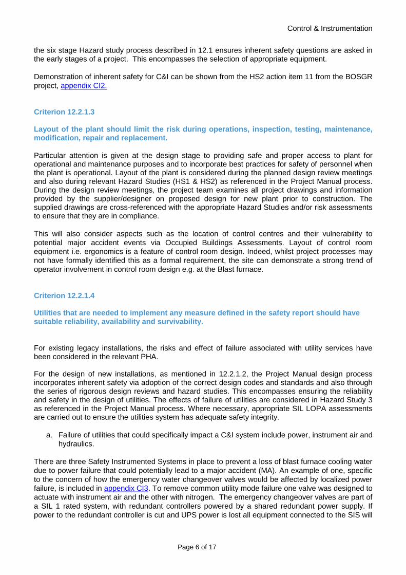
Control & Instrumentation
Page 6 of 17
the six stage Hazard study process described in 12.1 ensures inherent safety questions are asked in the early stages of a project. This encompasses the selection of appropriate equipment. Demonstration of inherent safety for C&I can be shown from the HS2 action item 11 from the BOSGR project, appendix CI2. Criterion 12.2.1.3
Layout of the plant should limit the risk during operations, inspection, testing, maintenance, modification, repair and replacement. Particular attention is given at the design stage to providing safe and proper access to plant for operational and maintenance purposes and to incorporate best practices for safety of personnel when the plant is operational. Layout of the plant is considered during the planned design review meetings and also during relevant Hazard Studies (HS1 & HS2) as referenced in the Project Manual process. During the design review meetings, the project team examines all project drawings and information provided by the supplier/designer on proposed design for new plant prior to construction. The supplied drawings are cross-referenced with the appropriate Hazard Studies and/or risk assessments to ensure that they are in compliance. This will also consider aspects such as the location of control centres and their vulnerability to potential major accident events via Occupied Buildings Assessments. Layout of control room equipment i.e. ergonomics is a feature of control room design. Indeed, whilst project processes may not have formally identified this as a formal requirement, the site can demonstrate a strong trend of operator involvement in control room design e.g. at the Blast furnace. Criterion 12.2.1.4
Utilities that are needed to implement any measure defined in the safety report should have suitable reliability, availability and survivability. For existing legacy installations, the risks and effect of failure associated with utility services have been considered in the relevant PHA. For the design of new installations, as mentioned in 12.2.1.2, the Project Manual design process incorporates inherent safety via adoption of the correct design codes and standards and also through the series of rigorous design reviews and hazard studies. This encompasses ensuring the reliability and safety in the design of utilities. The effects of failure of utilities are considered in Hazard Study 3 as referenced in the Project Manual process. Where necessary, appropriate SIL LOPA assessments are carried out to ensure the utilities system has adequate safety integrity.
a. Failure of utilities that could specifically impact a C&I system include power, instrument air and hydraulics.
There are three Safety Instrumented Systems in place to prevent a loss of blast furnace cooling water due to power failure that could potentially lead to a major accident (MA). An example of one, specific to the concern of how the emergency water changeover valves would be affected by localized power failure, is included in appendix CI3. To remove common utility mode failure one valve was designed to actuate with instrument air and the other with nitrogen. The emergency changeover valves are part of a SIL 1 rated system, with redundant controllers powered by a shared redundant power supply. If power to the redundant controller is cut and UPS power is lost all equipment connected to the SIS will

Control & Instrumentation
Page 7 of 17
revert to its safe state. The emergency water valves safe state is fail open to maintain water supply to the furnace. Criterion 12.2.1.5
The safety report should show that appropriate measures have been taken to prevent and effectively contain releases of dangerous substances. Carbon monoxide detectors have been installed at a number of locations in the Establishment. These are used to warn personnel of a gas release and hence to restrict their exposure to the harmful effects of carbon monoxide. Dispersion modelling has been carried out to determine the potential harm outside the Establishment from Blast Furnace Gas and Basic Oxygen Steelmaking gas. The output of the modelling was used to position a series of CO detectors, known as the PIZ Chain, which are designed to give early warning of a gas hazard that could affect off-site populations. These CO detectors, which number 143 in total, are housed on 96 posts (43 posts have 2 detectors on, this is due to there being an elevated section in close proximity to the posts, so double detection was installed at 2m and 6m heights to ensure no release of toxic gas is missed). The posts are ~15m apart from each other. The 96 posts have been located to ensure that at least 2 detectors register any gas release heading in an off-site the direction. The detectors are linked to display and alarms at Energy Control. See the Energy report for information on the actions that will be taken in the event of the alarms activating. The detectors have recently been slightly relocated due to the routing of a new public road that cuts across the existing chain and at the same time the make and model of the detector updated to represent current best technology. Both changes were subject to Management of Change. The technology employed by the detection sensor is an electrochemical cell technology (a description of how this technology works can be found in BS EN 45544-4). The system has been designed to BS EN 45544-4. We have recognised that there is a risk of poisoning of the cell by other contaminants, to counteract this risk we have utilised an auxiliary filter, which prevents the cell itself being directly exposed to the contaminant. There is a maintenance regime in place, which is managed via SAP, which is the business computerised maintenance system. Testing Procedures are available and are treated as controlled documents with approval routes and escalation procedures for change requests. On site there are approximately 500 fixed carbon monoxide detectors in areas where gas releases have historically occurred. All alarm locally both visually and audibly and some are linked back to the area control rooms. Criterion 12.2.1.6
The safety report should show that all foreseeable direct causes of major accidents have been taken into account in the design of the installation. Particular attention is given at the design stage, through the Project Manual, to consider the control, instrumentation and electrical systems are correctly designed to published best practices guidance such as BS 6739:2009, Code of practice for instrumentation in process control systems: installation and practice and site standard “RES006, Management and Development of Process Control computer systems and networks”, appendix 2.13. Failures in control, instrumentation and electrical systems will be considered during the relevant six stage Hazard Studies process as referenced in the Project Manual process and the potential as a direct cause of failure.

Control & Instrumentation
Page 8 of 17
TSSP PT recognises the important of best practice guidance such as BS 6739:2009, Code of practice for instrumentation in process control systems: installation and practice. However, it is recognised that a formal roll-out plan for the site to ensure a consistent approach for instrumentation and control system for correct selection and design is in need of development, and is an improvement plan item. Criterion 12.2.1.7 Addressed in Mechanical section. Criterion 12.2.1.8 Addressed in Mechanical section. Criterion 12.2.1.9
The safety report should show that materials of construction used in the plant are suitable for the application. Following the hazardous area classification, the design process ensures that the equipment specified for the duty meets all the requirements. This is followed by specifying and supervising the installation and commissioning phases of the project to ensure full compliance to the demands of the hazardous area classification. For safety instrumented systems the safety requirement specification documentation, looks at the potential of the environmental condition and guides the selection of these systems to protect against corrosion/erosion. The equipment design, in terms of material of construction, is then checked within the functional safety assessment stage 2 requirements. Following design phase during HS4 and HS5, there are checks on appropriate material selection. Further on in the safety instrumented system lifecycle, during the operation and maintenance phase, the safety instrumented function equipment is routinely visually inspected to confirm installation remains physically sound, with no evidence of corrosion/erosion damage. See also criteria 12.2.1.6 and improvement plan action item. Criterion 12.2.1.10
The safety report should show that adequate safeguards have been provided to protect the plant against excursions beyond design conditions. The policy of this company for ensuring an appropriate overall process control strategy is given in “RES006, Management and Development of Process Control computer systems and networks” (Appendix 2.13). This Engineering standard relates to the management and development of Process Control computer systems used for controlling and monitoring manufacturing and transport operations across the site. On the majority of process unit, the basic process control system will provide the initial means of operating within the design conditions. Further safeguards include a combination of alarms, trips and interlocks.

Control & Instrumentation
Page 9 of 17
Where possible automated instrumented systems are preferred to alarms, although it is recognized that there are a number of processes (e.g. Blast Furnaces and Gas distribution), where it is not always feasible to automate shutdowns to safe states. However, continuous improvement often enables automatic systems to be identified, designed and installed, as can be demonstrated during Blast Furnace 4 rebuild project 2012/13. The HS3 process identified several potential SIL rated systems. A number of these systems were designed and installed to achieve SIL 1 reliability. These details are available on request. Alarm Handling is recognised as a key human factors topic, and TSSP PT recognises this within the company process control standard “RES006, Management and Development of Process Control computer systems and networks”, appendix C&I-2013GSR-APPX-002. A number of control rooms have been assessed against the EEMUA Publication No. 191 "ALARM SYSTEMS. A Guide to Design, Management and Procurement". However, it is recognised that a formal roll-out plan for the establishment for consistent alarm handling is in need of development, and is an improvement plan item. Criterion 12.2.1.11
The safety report should describe how safety related control systems have been designed to ensure safety and reliability. The policy of this business for achieving functional safety of safety related control systems (SRCS) is given in “TSSP UK Management of Safety Related Control Systems” (Appendix 2.10). This site standard describes the system for managing the lifecycle of Safety related control systems.

Control & Instrumentation
Page 10 of 17
Study
Design
Build
Use
Decommission
1a. Hazard and Risk assessment StudyIdentify hazard potential
Estimate risk consequence & frequency
2. Allocation of safety functions to protection layers
2a. Identify risk reduction contributions2b. Define risk reduction contribution
from SIS2c. Determine SIL for each SIS function
3. Safety requirement specification for each rated
SIF
4. Design & Engineering of SIS
5. Installation, commissioning & validation
6. Operation & Maintenance
7. Modification
8. Decommissioning
Phase
Design & Engineering other
means risk reduction
Task
Stage 1 FSA, after PHA
Stage 2 FSA, after design
Stage 3 FSA, prior identified hazard being
present
Stage 4 FSA, after operation & maintenance experience
gained
Stage 5 FSA, after modification & prior decommissioning
Safety Instrumented Systems – Documentation process & requirements
DocumentationGuidance/Tool
1b. Define acceptable risk frequency
1c. Determine overall risk reduction required
SIL 1 or more?
NO
YES
YES
Basic process control and/or
asset protection function
NO
Safety Instrumented function
PHA Study template – HAZOP/PHR/what if
TSSP UK Risk Criteria
All SIL 1 and above systems must be
documented within central Site inventory.
TSSP UK LOPA template
TSSP UK FSA guidance,TSSP UK Standard Proof Testing & Maintenance
TSSP UK SIS Site Inventory
TSSP UK SRS template
TSSP UK model template for SIL rated
systemsTSSP UK proof testing
template
Documentation hi-lighted in bold are mandatory for all SIS rated SIL 1 or above
TSSP UK guide operation & maint SRCS
within SAP
TSSP UK MoC ref num
FATSAT
Loop Testing / sequence Testing
Proof test auditFinal commissioning
PHA, HAZOP/PHR/FTA
LOPA is the Tata preferred tool for SIL assignment
All SIF with a SIL 1 or above must have a SRS
prior to design
For a SIF rated SIL 1 or above a stage 3 FSA is
mandatory
Any new SIS rated SIL 1 or above, or any
changes in existing SIS require a MoC
In addition to the main policy document there are supporting procedural documents and templates dealing with various topics associated with functional Safety Systems, these include competency, design and engineering and proof testing, a full list can be seen in appendix C of the policy document.
Control & Instrumentation
Page 11 of 17
The inventory of safety related control systems that are SIL1 or higher is maintained within a central electronic Lotus notes database called “Management of Risk”. A summary of the site inventory is included within appendix CI10. These control systems are designed in accordance with BS EN 61511. Detailed examples of SRCS are included in the works area safety reports. Criterion 12.2.1.12
The safety report should show how systems which require human interaction have been designed to take into account the needs of the user and be reliable. The six stage hazard study process, within the project manual, ensures that project teams assess and review aspects such as alarm management and the layout of control rooms. The main aspect of these processes in the design phase is to put into place automated systems, which do not rely on operator response for significant incidents. Reliance on operators to perform a safety related function with a reliability of less than 0.1 is rare in Strip UK. Where this has been identified through a LOPA analysis, a full human failure assessment is carried out on the procedure. See Human Factors section for more detail. A review of alarm handling has been carried out for the Energy Control rooms to ensure that only truly safety related alarms are assigned as such. The PHA studies were used to identify the safety requirements and the responses. For the new blast furnace 4 a review of alarms has been carried out. A small number (14) of high priority alarms has been identified and local job aids produced to help the operators take the correct immediate response. See Ironmaking section. Criterion 12.2.1.13
The safety report should describe the systems for identifying locations where flammable substances could be present and how the equipment has been designed to take account of the risk. The policy of this company for the identification and classification of Hazardous areas is given within the site standard “TSSP UK DSEAR Management Policy” (Appendix 2.7). This site standard describes the management process, in line with POPMAR (HSG 65). In addition to the policy document there is a supporting procedural document dealing with the control of electrical and non-electrical ignition sources, this covers portable and transportable electrical equipment used in hazardous areas, see “TSSP UK Control of Electrical Ignition sources” (Appendix 2.8) Detailed examples of identification and classification of Hazardous areas are included in the works area safety reports. Criterion 12.2.2.1
The safety report should show that the installations have been constructed to appropriate standards to prevent major accidents and reduce loss of containment.

Control & Instrumentation
Page 12 of 17
The construction of new installations is properly managed in accordance to guidelines in Project Manual. As described in 12.2.1.1, the codes & standards relevant to the new installations are identified at the beginning of the project and are recorded in the Framework Agreement between the Contractor and TSSPUK. For equipment supplied to TSSPUK, the application of a CE mark and Certificate of Conformity (or Incorporation for partly build equipment) provide traceable evidence that it has been supplied according to the relevant Directive. Additionally, as part of the CE Marking process where TSSPUK must certify the system as a whole, check sheets are created against relevant directives and standards to ensure that the essential safety requirements have been adhered to. This is in addition to Hazard Study 4, which checks and assures construction of the project as per design intent, that actions from previous Hazard Studies have been fully implemented into the design and installation, that the operating instructions and emergency procedures comply with any requirements identified by previous Hazard Studies and are satisfactory for safe operation. Criterion 12.2.2.2
The safety report should describe how the construction of all plant and systems is assessed, and verified against the appropriate standards to ensure adequate safety. With respect to the management and assessment of changes arising during construction and after the Design Freeze these are recorded on a Change Control Register, rather than the site MofC procedures. Guideline 2.3.2.5, Construction Change Control, within the project manual describes this process. Early in the project phase, within the project manual, the requirement for each safety instrumented system is specified, in terms of the required safety instrumented functions and their associated integrity, in order to achieve the required functional safety. The safety requirement specification (SRS) documents for each safety instrumented function the record of the design requirements and the history of where the requirements have come from. Two functional safety assessments (FSA) are carried out during the project design phase for each safety instrumented system, functional safety assessment stage 1 and 2. A further functional safety assessment, stage 3, is carried out after installation, pre-commissioning and final validation of each safety instrumented system and prior to process fluids being introduced. The stage 3 assessments, in addition to completion of hazard studies 4 and 5, ensure that functional safety has been achieved by the safety instrumented system based on compliance with the relevant clauses of BS 61511. An example of the documented results of one of these assessments, stage 2, is included in appendix CI9. Criterion 12.2.3.1
The safety report should show that safe operating procedures have been established and are documented for all reasonably foreseeable conditions.
Safe working procedures (SWPs) are in place for all work undertaken at TSSPUK including operating procedures, maintenance tasks and operations tasks. All SWPs are maintained in a Lotus Notes database system that is also accessible through the company intranet. This system ensures the most up to date procedure is available and printed out copies are not valid.
In general operating procedures are created by the people who carry them out and are reviewed by other operators before being finally approved by the unit engineer.

Control & Instrumentation
Page 13 of 17
For legacy processes the SWPs are well established. The PHA process has identified the need for procedural updates and changes as more risk reduction requirements are identified. In addition the Management of Change process determines the need to update procedures to reflect modified plant. For all updates to procedures, there is a review and approval process that is integral to the database.
Criterion 12.2.4.1
The safety report should show that an appropriate maintenance scheme is established for plant and systems to prevent major accidents. SAP is used as the management system for triggering and recording routine data collection activities, analysis, reporting and notification of defects, anomalies or remedial work requests. Frequency of data collection is based on a number of key elements: Criticality of asset, Failure Modes, History, Experience, Plant Operation. The planning, scheduling and recording of maintenance activities is facilitated within SAP:
• SAP is a Computerised Maintenance Management System. It is utilised throughout Strip UK, in addition to the rest of TSE, and forms part of the Engineering Management System.
• There is a flagging system used in SAP to identify statutory mandatory and safety critical tasks and there is a zero tolerance philosophy applied to the schedule adherence of these tasks. Controls are in place to ensure they cannot be cancelled without approval. Those tasks tagged with the statutory mandatory marker within SAP evoke additional protocol around governance and execution of the maintenance / inspection tasks. A further control is adopted for tasks deemed as safety critical such as those on COMAH assets. This ensures the critical job content such as frequency can only be amended by those authorised to do so and requires a management of change process to be followed.
• Preventive Maintenance tasks are marked with the above-mentioned safety controls to ensure they are identified as a priority over other routine maintenance. These are held and controlled within a dedicated database and are hyperlinked to each SAP maintenance task list. Each unique RA / SWP can then be viewed and printed for each occurrence of the job.
• Each job contains key information, i.e. job instruction, work centre responsible for the work, duration, number of individuals required to carry out the task, spares, procedures etc.
• Emerging or unplanned work can be identified whilst conducting preventive inspections or via breakdowns. Emerging work is prioritised by the requester using a Risk Assessment Matrix. This provides with an understanding of whether the work is an emergency or not.
• For non-emergency work, a daily review is carried out where a list of identified work is reviewed and reprioritised if required. This work can then be planned and scheduled into weekly or shut down work lists.
For Safety Instrumented Systems The policies and procedures for operating the plant are given in “TSSP UK guide operation and maintenance of SRCS”, appendix CI11. One of the objectives of the operating policy is to ensure that the designed safety integrity of the safety instrumented system is maintained. An example from the mills area is representative – Semi-Confined Explosion in the Continuous Annealing Process Line (CAPL). The protection system is the oxygen analyzer control loop, which will shut off the hydrogen supply to the CAPL furnace in the event of high oxygen being detected within the CGJC chamber. Appendix CI6 shows the written proof-test procedure designed to identify undiagnosed failures on the safety function. It is based on the MTI method of failure identification. There are two oxygen analyzers in this safety instrumented system, AY40-136 and AY40-138; both are treated as separate tests.

Control & Instrumentation
Page 14 of 17
The proof tests on analyzer AY40-136 trip loop are split into two types; • Full Proof Test – Where complete loop is tested i.e. from O2 analyzer through to isolating the
H2 supply to the furnace • Partial Proof Test – Where the O2 analyzer through to the hardwired relay to the AGSRI
Cabinet is tested, i.e. these are the relays that automatically isolate the H2 supply to the furnace. (The purpose of the Partial test is to check the least reliable part of the SIS loop, the O2 analyzer/sensor)
Appendix CI4 shows an example of a completed proof test for this system. The document in appendix CI7, shows typical information maintained on system failure and demand rates. Any system failure data is maintained within SAP following scheduled maintenance. The document in appendix CI7, show how typical audit and test results on this safety instrumented system are maintained. A non-conformance report for dealing with faults or failures within this system is included in appendix CI8. For fixed electrical systems HV and LV. The company has a set of Electrical Safety rules, EIS 7 on Low voltage safety rules, appendix 1.21, and EIS 5 on High voltage safety rules, appendix 1.20. These Electrical Safety Rules are based on current industry standards (the curent editions of the Electricity at Work Regulations and the Health and Safety at Work Act). The “Management of Electrical Safety” document, appendix 2.14 provides the framework for the management of Electrical Safety to be used in conjunction with the High Voltage Safety rules (EIS 5) and Low Voltage Safety rules (EIS 7). For Hazardous Area Classification and Control of Ignition (DSEAR) This procedural document for the selection, installation, maintenance and inspection of electrical equipment in order to minimise the risk of ignition in hazardous is given in “TSSP UK Control of Electrical Ignition sources” (Appendix 2.8). One of the objectives of this procedure is to ensure a consistent standard for the inspection and maintenance of all equipment installed in hazardous areas. Criterion 12.2.4.2
The safety report should show that there are appropriate procedures for maintenance that take account of any hazardous conditions within the working environment. Maintenance and inspection tasks are drafted into a Risk Assessment Safe Working Procedure (RA/SWP) document that takes into consideration the working environment under which the maintenance task is executed, the specific risks associated with the identified activity, the proximity to dangerous plant and the safe access/egress. The RA/SWP document undertakes a full Risk Assessment and identifies and ranks all the risks associated with the task. Preventative measures are identified and become part of the task. The Risk Assessment specifically identifies:
• Safe Method of Work; Isolations, permits, etc • Personal Protective Equipment (PPE) • Tools/Equipment requirement (e.g. BA, scaffolding, gas monitor, etc) • Safe Access and Egress for the task • Manning Levels

Control & Instrumentation
Page 15 of 17
• Competency Requirements for the person executing the task (e.g. must have relevant training for the task i.e. gas awareness training, local induction and any other specific requirements for the task)
Once approved the RA/SWP document is locked for editing and kept in the SWP database for each respective works area. Each document contains a link to the Local Emergency and Local Environmental Emergency plan together with emergency contact numbers. The full RA also includes the requirement for a two-minute Risk Assessment to be carried out at the face of the work, prior to any activity. An example of a maintenance procedure for a proof test is shown in appendix CI5. Included within the maintenance procedures are the actions and constraints that are necessary to prevent and/or reduce the consequence of a hazardous event during these checks. The document also includes the full maintenance checklist to ensure the equipment runs safely and effectively. Any issues captured are fed back into SAP. In addition, and as previously described, the Company has a set of Electrical Safety rules, EIS 7 on Low voltage safety rules and EIS 5 on High voltage safety rules. Criterion 12.2.4.3
The safety report should show that systems are in place to ensure that safety critical plant and systems are examined at appropriate intervals by a competent person. The persons/ departments that are responsible for managing the use of safety instrumented systems on this site are described in “TSSP UK Management of Safety Related Contrl Systems“ section 4. The competence of the persons identified as responsible for managing the use of safety instrumented systems is described within procedure document “TSSP UK Safety Related Control Systems - Competency”, (Appendix 2.11). The business policies and procedures in Criterion 12.2.4.1 detail the competence requirements for DSEAR and electrical systems. Criterion 12.2.4.4
The safety report should show that there is a system in place to ensure the continued safety of installation based on the results of periodic examinations and maintenance. Criterion 12.2.4.1 describes the asset management systems and processes, and the feedback mechanisms to input the results of inspection and examinations. Work notifications are described as the means by which rectification/remedial actions are scheduled, and a comprehensive system of measuring and monitoring KPI’s is in place. Monitoring of performance of the Safety Related Control Systems is carried out at plant level, and discussed at local plant/area meetings. A number of elements are monitored for all plants and this information uploaded into the Lotus notes Management of Risk database. Key data include the following:
• Compliance with proof testing frequencies. • Non-conformance of proof test or maintenance plan. • Operation of the Safety related control system.
Control & Instrumentation
Page 16 of 17
Where there are any interventions by a SRCS or non-conformances, there is an investigation carried out to identify the reason for the operation, and what can be done to prevent a recurrence. Criterion 12.2.5.1
The safety report should describe the system in place for ensuring modifications are adequately conceived, designed, installed and tested. The TSE management of change system is defined in Code of Practice HSC-08 Management of Change (Appendix 1.15). This is implemented in TSSPUK through the Management of Change Policy and Procedures (Appendices 2.3 & 2.4). The TSSPUK MOC Policy states that any non-like for like changes within Strip Products UK must follow the MOC system, whether they be organisational, procedural, process or equipment.
The MOC system requires that the appropriate people complete a formal written risk assessment and that the change is authorised at a senior level in a Change Review Authorisation Group (CRAG) meeting. Before authorising changes, the authoriser assesses the quality of the MOC, risk assessment and any further control measures required. Process safety engineers based in the works areas give advice as to the appropriate level of risk assessment for the change. For the majority a simple five-step risk assessment is adequate but “what if” and HAZOP studies are also used for complex changes or where the hazard is greater.
The MOC system requires people to specify if changes to any of the following are needed:-
• Drawings
• Functional design specifications
• Training Material
• Operating Procedures
• Maintenance Procedures
For new capital projects, the six stage hazard study process is used and this forms the risk assessment requirements of the management of change system.
The requirements for any modification to safety related control system is defined in section 9.3 of the policy document “TSSP UK Management of Safety Related Control Systems”. Process safety tasks, such as maintenance or proof testing for a SIL rated loop, are identified within SAP using a Safety Critical flag. If changes are made to the SIL rated loop, such as changes in test frequency, spares, etc, a Management of Change number is required. A change cannot be made until an entry is made and all changes are recorded and reported to the Safety Department on a weekly basis. Criterion 12.3 Improvement Plan Improvement opportunities have been identified, generally where the site can demonstrate good practice but not necessarily consistently across the business. These will be managed as a general C&I Improvement plan, key aspects of which are:-

Control & Instrumentation
Page 17 of 17
- Determining a consistent approach to the design and selection of instrumentation and control systems
- Putting in place a formal system for consistent roll out of Alarm Handling

Section 12 Technical
Aspects Human Factors

Human Factors
Page 2 of 10
Criterion 12.1..................................................................................................................................... 3
Criterion 12.2..................................................................................................................................... 3
Criterion 12.2.1.1 .............................................................................................................................. 3
Criterion 12.2.1.2 .............................................................................................................................. 3
Criterion 12.2.1.3 .............................................................................................................................. 4
Criterion 12.2.1.4 .............................................................................................................................. 5
Criterion 12.2.1.5 .............................................................................................................................. 5
Criterion 12.2.1.6 .............................................................................................................................. 5
Criterion 12.2.1.7 to 12.2.1.11 ........................................................................................................ 6
Criterion 12.2.1.12 ............................................................................................................................ 6
Criterion 12.2.1.13 to 12.2.2.2 ........................................................................................................ 6
Criterion 12.2.3.1 ............................................................................... Error! Bookmark not defined.
Criterion 12.2.4.1 .............................................................................................................................. 8
Criterion 12.2.4.2 .............................................................................................................................. 8
Criterion 12.2.4.3 .............................................................................................................................. 8
Criterion 12.2.4.4 .............................................................................................................................. 8
Criterion 12.2.5.1 .............................................................................................................................. 9
Criterion 12.3...................................................................................... Error! Bookmark not defined.

Human Factors
Page 3 of 10
Criterion 12.1 The safety report should show a clear link between the measures taken and the major accident hazards described. The Tata Steel policy for the integration of Human Failure analysis into risk assessment describes:·
- How to identify safety critical tasks for analysis· - How to carry out Detailed Task Analysis on Safety Critical Tasks· - How to carry out Human Failure Analysis on key steps within safety critical tasks
The process allows potential human failures to be assessed and managed in line with the hierarchy of control, taking into account the type of human failures that are likely to be encountered. The process laid out in the policy means that any performance influencing factors are identified and optimised appropriately. Criterion 12.2 The safety report should demonstrate how the measures taken will prevent foreseeable failures which could lead to major accidents. Where safety critical tasks are identified through risk assessment, they are subjected to the process detailed in the document PSG-10.0.50 “Human Factors in Process Safety Risk Management”, appendix 1.29. During this process, human reliability is assessed to understand how it could potentially play a part in a major accident. A key part of the process is to optimize the performance influencing factors identified for the given tasks. Where a person is identified as having a “Safety Critical” role by using the process in the referenced document “Identification of Safety Critical Roles”, appendix HF1, they are highlighted on the SAP system. This information can be applied to a number of settings, for example, it is relevant when conducting organizational change. It can be used to prioritise the roll-out of various initiatives to Safety Critical personnel in the first instance. Criterion 12.2.1.1 The safety report should show that the establishment and installations have been designed to an appropriate standard. Addressed in other technical sections. Criterion 12.2.1.2
The safety report should show that a hierarchical approach to the selection of measures has been used. For all new projects undertaken in TSSPUK, the “Project Manual” is used. The Project Manual details all steps of the project life-cycle, from concept stage through to handover and close out. As a part of the definition stage of the process “Hazard Study 2” (HS2) (Appendix 1.12) is undertaken. Hazard Study 2 is the second of a suite of six specific methodologies for recording and assessing process hazards and risks in projects or modifications on high

Human Factors
Page 4 of 10
hazard facilities (HHFs). Section 2.3 of HS2 details how the hierarchy of control should be applied for all new designs and projects. As a part of the design process detailed in the Project Manual, Layer of Protection Analysis (LOPA) studies are undertaken. Members present in the team have been trained in Human Factors methods and practices. These studies provide a method for evaluating hazard scenarios and comparing them with risk tolerability criteria to determine if existing safeguards are adequate or if additional controls are required. When additional safeguards are required, they are assessed using a Cost Benefit Analysis (CBA) method. During the course of applying the CBA, the respective strengths of humans and machines are considered and will affect the type of safeguard recommended. This includes the implications of introducing latent error through maintenance and inspection where automated safeguards/systems are recommended. The need for manual intervention in critical systems is recognised and operators carrying out these tasks are identified in the “Identification of Safety Critical Roles”, appendix HF1, document, which in turn will influence their training and competence requirements. Where safeguards that involve a level of human interaction are recommended, the design of these will account for human performance and reliability, and will, where necessary inform competence and training profiles. When making recommendations for safeguards to be implemented, the correct performance of a Safe Working Procedure (SWP) will not form the sole safeguard, as human fallibility is recognised. SIL determination is carried out by competent, professional engineers, using a SIL/LOPA process. The outcomes of the SIL/LOPA process are presented on completion, for challenge to senior engineers, at which point Human Failure is considered. As the level of maturity increases in this process, a human factors specialist will be involved in the process. Criterion 12.2.1.3
Layout of the plant should limit the risk during operations, inspection, testing, maintenance, modification, repair and replacement. Where maintenance tasks are identified as safety critical, they are subjected to the process in the policy PSG-10.0.50 “Human Factors in PSRM”, appendix 1.29 This ensures all relevant Performance Influencing Factors are managed. This includes the availability of resources such as P&IDs. The policy also stipulates that relevant personnel must be included in the task analysis process in order that the nature of the task is accurately represented. In the process of designing new systems, or modifying existing plant, the design verification stage in the project manual ensures that maintainability of the new equipment is accounted for from a Human Factors perspective. Hazard Study 5 stage in the project manual ensures that all parts of the plant that require it are labelled. The Human Factors considerations within Hazard Study 3 stage of the Project Manual ensures that suitable attention is given to environmental factors with regard to human performance in the initial design stages.

Human Factors
Page 5 of 10
Criterion 12.2.1.4
Utilities that are needed to implement any measure defined in the safety report should have suitable reliability, availability and survivability. Requirements for Uninterruptible Power Supply systems are assessed and designed on an individual basis. Competent, professional engineers are involved in the designing of the systems, and ensure that Human Factors aspects are considered In order to ensure Human Factors considerations are formally addressed when implementing UPS systems, a Safety Report Improvement Plan action (Criterion 12.3) has been generated. Criterion 12.2.1.5
The safety report should show that appropriate measures have been taken to prevent and effectively contain releases of dangerous substances. Addressed in other Technical sections. Criterion 12.2.1.6
The safety report should show that all foreseeable direct causes of major accidents have been taken into account in the design of the installation. The policy document PSG-10.0.50 “Human Factors in PSRM”, appendix 1.29 details how safety critical tasks are identified in relation to MAH scenarios. The policy is applicable for all types of task – routine, non-routine, operations, maintenance inspection and testing. Safety critical tasks that are identified as requiring a human failure analysis are prioritised on a risk basis (i.e. possible number of fatalities) with the greatest risk tasks being given priority. Where two tasks have the same risks, they are prioritised based on the perceived likelihood of the human failure occurring. To ensure a balanced and “real world” approach is adopted in each of the analyses, the policy requires that operators currently responsible for the task, in addition to experienced experts are present in the analysis sessions. Where a full human failure analysis is required, the analysis team highlights the most critical steps in the task, upon which a full analysis is conducted using Human HAZOP Guidewords. A critical step is identified as one in which there is little or no recovery opportunity to stop a hazard from being realised, or a step which if not carried out means the rest of the task cannot continue. Several quidance documents support the implementation of the “Human Factors in PSRM” policy. Among these is PSG-10.0.52 “Human Failure Analysis for PSRM”, appendix 1.30 which details how a HFA should be conducted. The document includes a comprehensive list of Human Failure Types and Performance influencing factors that are to be used when carrying out the analysis. The policy details what actions should be taken as a result of the human failure analysis process. Where actions are required to optimise performance influencing factors, the hierarchy of control is used. Examples of completed analyses are included as HF2, HF3, & HF4 of the appendices.

Human Factors
Page 6 of 10
Criterion 12.2.1.7 to 12.2.1.11
Addressed in other Technical sections. Criterion 12.2.1.12
The safety report should show how systems which require human interaction have been designed to take into account the needs of the user and be reliable. When designing new plant or equipment, the project manual, in addition to competent, professional engineers with Human Factors/Ergonomics experience and training, guide the project team to consider Human Factors principles at all stages in the development life cycle. A key part of this process is to include font line personnel though-out. Including personnel with HF knowledge in the project team also allows the identification of the procedural and training needs of the potential users. Tata Steel Strip Products operate legacy plant in many areas of the Port Talbot site, and as such, the centralisation of control rooms is not uniform. Where new plant is designed or modified, consideration is given to the centralisation of the control rooms. An example of this would be the Blast Furnace safe haven building, which houses the control systems for both Blast Furnaces 4 and 5. Where new control rooms and systems are required, operator involvement is sought and their feedback is incorporated in the designs. An example of this is the control panels and screens for the recently rebuilt Blast Furnace 4. In consultation with the operators, past and present, it was decided that a design closely resembling that of Blast Furnace 5 would be an acceptable design (albeit with some additional improvements) as it allowed consistency and familiarisation between furnaces. LOPA studies undertaken on items of plant identified by the safeguard register identify critical alarms. The design, prioritisation and rationale of these alarms is overseen by competent engineers who are responsible for incorporating Human Factors considerations into the process. Criterion 12.2.1.13 to 12.2.2.2
Addressed in other Technical sections. Criterion 12.2.3.1
The safety report should show that safe operating procedures have been established and are documented for all reasonably foreseeable conditions. TSSPUK is currently in the process of implementing a new system for creating safety critical procedures. The process is outlined in the policy document PSG-10.0.50 “Human Factors in PSRM”, appendix 1.29 it is envisioned that in the future a somewhat diluted version of this policy will be applied to the writing of all safe working procedures. Adopting the process detailed in the policy document will ensure that the context of procedure is informed by task and human failure analysis. A policy for procedural support (“Procedure for Procedures”) is in the process of being created. The policy document will identify the required level of procedural support for a given task, and will be supported by documents that specify how each of the different levels of procedural support should be created, managed and controlled. Safe Working Procedures are managed through a Lotus Notes database system, which enables automatic review

Human Factors
Page 7 of 10
periods, approval routes and other such control measures. As a part of the procedural support process, some tasks may be found to need no written procedures and will instead rely on competence. In this case, the TSSPUK competence assurance system will be responsible for ensuring the required level of competency for people carrying out the task. Process Safety awareness courses are delivered by Process Safety Engineers in each of the areas of site, and enable the communication of information surrounding Major Accidents and their respective control measures. Shift handovers within TSSP are a key part of the safety critical communication process and must be to a high standard to ensure the safety and integrity of the plant. The company is in the process of investigating the feasibility of a standardised process for shift handovers. A small investigation and observation of shift handover practices has taken place, and trial runs of new systems and practices that represent best practice have taken place. The findings of this investigation are found in the document “Improving shift handover practices at Tata Steel Strip Products” (Appendix HF5). The “Blast Furnace pilot” programme addresses staffing levels in the organisation, and the supervisory responsibilities in the context of Major Hazards. The pilot scheme is gradually being implemented in other areas of site. A large percentage of the organisation is currently undergoing an organisational review, during which staffing levels and workload will be accounted for. Management of organisational change, and the document “Identification of Safety Critical Roles”, appendix HF1, will be used to assess changes in safety critical roles across site. It is acknowledged that fatigue can arise from excessive working time and poorly designed shift patterns. To this end, the Fatigue Risk Index tool was used to assess the shift patterns at TSSP. The results of this study showed that while broadly acceptable, the shift pattern left little room for manoeuvre before it was perceived as too high a risk. A potential problem was overtime as it reduced the amount of rest time and in some cases meant individuals working more than 12 hours in a 24-hour period. Overtime rates are controlled from a financial perspective, which goes some way to reducing the amount of overtime hours worked by individuals. However, it is appreciated that this does not monitor overtime or fatigue on an individual basis. Fatigue management will be a subject for the Human Factors Improvement plan (Criterion 12.3), especially focused on people expected to undertake safety critical roles. Organisational Culture is identified as a major influence on safety performance within TSSP and is considered during the Human Failure Analysis stage as a performance-influencing factor. In 2005, culture was identified as a major issue within the business, and in order to remedy this, a cultural change initiative called “The Journey” was established. The Journey sought to improve culture through a number of core values to determine how every person, at every level of the business should conduct their self. One of the key vessels for communicating the messages of the Journey are “Journey Days” these days are held for all employees in the business each year and provide an opportunity to discuss many issues including safety. A major facet of these days, and the Journey in general is that challenging people is accepted and expected. A just culture is fostered through this, and while difficult, the existing blame culture is slowly being replaced. Behavioural Safety is in its infancy at TSSP, and the limitations are well understood. Historically, accident rates have been the main way of tracking safety performance, however as the organisation matures, more focus on leading rather than lagging indicators is beginning to be implemented. Accident and injury rates are still recorded, but these are now

Human Factors
Page 8 of 10
included alongside other indicators such as High Potential Occurrences, near misses and Losses of Containment. This ensures the focus is not solely on personal injury. Locally, Human Factors in accident investigation is given consideration by accident investigators who have had training in Human Factors. This enables the investigators to identify any Human Factors issues that could have caused the accident. In more complex cases, the investigators will defer to the Human Factors Specialist, who will advise or provide assistance as required. At a group level, Tata Steel Europe is in the process of creating a Code Of Practice to govern how accident investigations should be conducted. Within this standard will be guidance on using Human Factors methods in accident investigation. At higher levels of investigation it will be compulsory to use the Human Factors methods during the investigation. Criterion 12.2.4.1
The safety report should show that an appropriate maintenance scheme is established for plant and systems to prevent major accidents. As a part of the PSG-10.0.50 “Human Factors in PSRM”, appendix 1.29, policy, maintenance tasks are treated equally to operational tasks in relation to their needing analysis. As a part of the rolling programme of analysis, safety critical procedures will be updated. As discussed in criterion 12.2.1.3, relevant personnel are involved through the process, enduring the knowledge and experience is utilized. As a result of analyses, it would be usual for recommendations to including ensuring the availability of P&ID’s, job aids, tools etc. Criterion 12.2.4.2
Addressed in other Technical sections. Criterion 12.2.4.3
The safety report should show that systems are in place to ensure that safety critical plant and systems are examined at appropriate intervals by a competent person. The competence assurance system that is currently in the process of being implemented at TSSP ensures that personnel and contractors who are expected to carry out examinations, inspection and proof testing are competent to do so. One of the competencies required to work in a particular area is the requirement to have undergone a local induction, the induction process will ensure the people in the area are fully aware of the local major hazards and their consequences. Criterion 12.2.4.4
Addressed in other Technical sections.

Human Factors
Page 9 of 10
Criterion 12.2.5.1
The safety report should describe the system in place for ensuring modifications are adequately conceived, designed, installed and tested. The TSE management of change system is defined in Code of Practice HSC-08 Management of Change (Appendix 1.15). This is implemented in TSSPUK through the Management of Change Policy and Procedure, appendices 2.3 and 2.4 The TSSPUK MOC Policy states that any non-like for like changes within Strip Products UK must follow the MOC system, whether they organisational, procedural, process or equipment. The system requires that the appropriate people complete a formal written risk assessment and that the change is authorised at a senior level in a Change Review Authorisation Group (CRAG) meeting. Before authorising changes, the authoriser assesses the quality of the MOC, risk assessment and any further control measures required. Process safety engineers based in the works areas give advice as to the appropriate level of risk assessment for the change. For the majority a simple five-step risk assessment is adequate but “what if” and HAZOP studies are also used for complex changes or where the hazard is greater. All three of these risk assessment methods consider Human Factors at various stages. Organisational changes are managed in the same way as any other changes would be in the MOC system. Safety Critical roles are taken account of in organisational change, as in workload expectations and fatigue. As the business matures, it is expected that a Human Factors Specialist would be involved in the organisational change process.

Human Factors
Page 10 of 10
Criterion 12.3 Improvement Plan.
Although significant progress has been made against Human Factors, there are still a number of elements that need to be implemented and improved within the business. Therefore an Improvement Plan has been determined.
Human Factors Improvement Plan
2013 2014 2015 2016 2017
Human Factors in Design (2014 – 2017)
Procedures (2013 – 2015)
Safety Critical Communications (2014 – 2016)
Fatigue Management (2014 – 2016)
Competence Assurance (2013-Ongoing)•Safety Critical Roles
•Safety Critical Tasks
•Overtime Management (Beyond WTD)
•Environmental and Individual Factors
•Adherence to Standards
•Alarm Handling/Control Room Design
•Procedure for Procedures
•Shift Handover Standardisation

Section 12 Technical Aspects
Mechanical

Mechanical
Page 2 of 21
CRITERION 12.1 .................................................................................................................. 3 CRITERION 12.2 .................................................................................................................. 4 CRITERION 12.2.1.1 ............................................................................................................ 4 CRITERION 12.2.1.2 ............................................................................................................ 6 CRITERION 12.2.1.3 ............................................................................................................ 7 CRITERION 12.2.1.4 ............................................................................................................ 8 CRITERION 12.2.1.5 ............................................................................................................ 9 CRITERION 12.2.1.6 .......................................................................................................... 10 CRITERION 12.2.1.7 .......................................................................................................... 11 CRITERION 12.2.1.8 .......................................................................................................... 12 CRITERION 12.2.1.9 .......................................................................................................... 12 CRITERION 12.2.1.10 ........................................................................................................ 13 CRITERION 12.2.1.11 ........................................................................................................ 14 CRITERION 12.2.1.12 ........................................................................................................ 14 CRITERION 12.2.1.13 ........................................................................................................ 14 CRITERION 12.2.2.1 .......................................................................................................... 14 CRITERION 12.2.2.2 .......................................................................................................... 15 CRITERION 12.2.3.1 .......................................................................................................... 16 CRITERION 12.2.4.1. ......................................................................................................... 17 CRITERION 12.2.4.2 .......................................................................................................... 18 CRITERION 12.2.4.3 .......................................................................................................... 19 CRITERION 12.2.4.4 .......................................................................................................... 20 CRITERION 12.2.5.1 .......................................................................................................... 21 CRITERION 12.3 ................................................................................................................ 21

Mechanical
Page 3 of 21
Criterion 12.1 The safety report should show a clear link between the measures taken and the major accident hazards described. Section 10 describes the predictive process used to identify and risk assess hazards in TSE. The PHA methodology is employed for initial identification and qualitative risk assessment of hazards. For high severity scenarios identified by this process, Layer of Protection Analysis (LOPA) is then used to quantify the risk by analysing causative mechanisms, condition modifiers and independent layers of protection. If the LOPA concludes that the risk is in the tolerable if ALARP zone, then a cost benefit analysis is carried out to determine if further risk reduction measures are proportionate to the risk reduction. For all risks, including those in the broadly acceptable region, low cost measures are always considered. In the case of societal risks, the ARI(COMAH) methodology was used to determine the tolerability of the risk. The works area sections of this safety report show the LOPAs for each of the scenarios in the representative set and, where necessary, the cost benefit analysis. A discussion on whether further low cost measures could be applied is also included. When identifying further risk reduction measures, the hierarchy of control principles are used. The six stage hazard study process for new projects (described in Section 10) ensures this approach for new designs. For the majority of legacy equipment the costs involved in improving inherent designs or layout mean they are disproportionate and therefore the majority of risk reduction measures for legacy equipment are control and instrumentation or improved procedural controls. In order to clearly illustrate the links between hazards and control measures Hazard and Safeguard registers have been compiled for each works area.
Table 12.1 – Hazard and Safeguard Register Template

Mechanical
Page 4 of 21
Criterion 12.2 The safety report should demonstrate how the measures taken will prevent foreseeable failures which could lead to major accidents. The hazard and safeguard register details the specific hazards and safeguards. In order to express the Basis of Process Safety for the plant a “Basis of Process Safety” table has been included in each works area report. This links the general MAH for a unit operation to the generic layers of protection for example inherent safety, mechanical integrity, control and instrumentation, human factors and emergency response.
Table 12.2 – Basis of Process Safety Template
Criterion 12.2.1.1 The safety report should show that the establishment and installations have been designed to an appropriate standard. It is TSSP UK policy to apply appropriate British/International codes and standards where they exist. TSSP UK will only develop its own guidance codes and standards in one of the following conditions:
- Further clarification of the code or standard is required. - The required code or standard is not covered by a British/International standard. - A higher standard is required to suit specific needs of the business.
For new build projects, the TSSP UK Project Manual has been created to provide a uniform and transparent approach to the governance of managing projects, by helping to adhere to relevant legislation, codes, standards, process and occupational safety criteria and capital spend. The manual guides the Project Manager and Project Team throughout the project life cycle, from idea generation in the Concept phase, through Definition, Implementation and finally Handover & Closeout. The Project Manual is based on the Association for Project Management (APM) Body of Knowledge (BoK). At the start of a project, the project team identify the relevant stakeholders, which may include internal specialist departments such as the Technology Group and RD&T and

Mechanical
Page 5 of 21
relevant specialist third parties including companies who design and/or supply the equipment. In consultation with these stakeholders, the project team records the relevant legislation that is applicable to the project and identifies the codes and standards that will satisfy the essential requirements of the legislation. The codes and standards specified by TSSP UK to prospective designers/contractors are recorded in an Enquiry Specification (PM 052)(Appendix 2.15), which is created by the Project Team and utilises a standard template from the relevant procedure (available via the Project Manual). The designers/contractors base their proposals, quotation and scope of work against the specifications set out in the Enquiry Specification. On receipt and assessment of all returned tenders, technical and commercial clarification meetings with bidders will take place as necessary to obtain full understanding of the proposals. Upon reaching agreement on all technical and commercial aspects a contract or selection is made and a Framework Agreement is created to formulate the contract between both parties. The relevant applicable codes, standards and regulations are recorded in this Framework Agreement along with the relevant specification documents, all of which are held on the project database. This contract and its documentation will form the basis upon which the design is progressed.
Prior to procurement, a series of Design Review processes (PM 014)(Appendix 2.17) takes place between the Project Team, Works Area, Contractor and any identified specialist departments and third parties. These meetings are formally documented and recorded in accordance with the set procedures defined in the Project Manual. The Design Review typically includes:
Application of codes and standards. Review of duty and specification (fit for purpose). Compliance with legislation. Operational and maintenance requirements. Human factors, process safety, occupational safety. Interfaces with other disciplines. Review of previous similar specifications
These design review meetings are intended to ensure that the designs are fit for purpose, safe to operate, comply with all statutory legislation, codes & standards and can be interfaced with the existing infrastructure at the appropriate location. Where it is necessary to deviate from the agreed code or standard, appropriate design calculations, simulations and necessary testing are conducted in order to demonstrate that the deviation provides a suitable level of integrity. For example, in the recent No.4 Blast Furnace rebuild project, PD5500 has been chosen as one of the major codes for design and construction in order to comply with the Pressure Equipment Directive and its essential safety requirements. For instance in the design of the new stove, PD5500 has been used in determining the basic stove shell thickness suitable for internal pressure, allowable stresses of the materials for construction, and combined stresses arising from the addition of wind, seismic and piping loads. The code is also used to determine the pressure reinforcement of openings (i.e. stove branches) for internal pressure. The static stress assessment and fatigue assessment of the stove design have been carried out to PD5500 Annex A and Annex C respectively whereas platform attachments are assessed to PD5500 Annex G. PD5500 is also adopted in the design of the blast furnace shell and the gas cleaning plant. There are a few areas in the design of No.4 Blast Furnace where the criteria of PD5500 were unable to be satisfied completely, some examples of the deviations are summarised below. For complete details of the rationales behind all the deviations from the PD5500, please refer to original document Deviations from PD5500, appendix M1.

Mechanical
Page 6 of 21
Examples:-
1. Rationale has been provided by the furnace designer for justifying their decision of
not adopting the PD5500 recommendation of post weld stress relieving all the stove or furnace shell plates that are in excess of 35mm thickness. A Notified Body under Pressure Equipment Regulations independently reviewed the justification and it has recommended that additional approval tests for all site welds in plates in excess of 35mm would negate the need for stress relief. The recommendation was subsequently accepted and implemented.
2. Rationales have been provided by the furnace designer for justifying their decision of not carrying out pressure test as per PD5500 on the furnace proper, gas cleaning plant, crude gas mains, stove and hot blast system.
3. Rationale has been provided by the furnace designer for justifying the decision of not adopting the recommended branch to shell weld details as set out in PD5500 Annex E. These weld details are designed and optimised via the use of pressure vessel design software. This has been reviewed and accepted by the Notified Body.
4. Rationale has been given by the furnace designer for justifying the decision of not including a full penetration butt weld at the joints where the cooling pipes pass through the furnace casing as recommended by PD5500 Annex E.
For legacy plant, where information on design is limited, the required integrity maybe be demonstrated through suitable inspection, maintenance and engineering critical analysis (ECA). More information inspection and legacy equipment is provided in the maintenance criteria.
Criterion 12.2.1.2
The safety report should show that a hierarchical approach to the selection of measures has been used. The Project Manual design process, as outlined in 12.2.1.1, incorporates inherent safety into new builds via adoption of the correct design codes or standards, compliance with relevant legislation and the six stage Hazard study process described in 12.1 ensures inherent safety questions are asked in the early stages of a project. This encompasses the selection of appropriate equipment. In the recent No.4 Blast Furnace rebuild project for example, various Hazard Studies have been carried out during the design phase. This includes HS3 studies, for example:- HAZOP studies of the Furnace Proper, Furnace Top, Gas Cleaning Plant, Furnace Top Gas Cooling System and Stoves and What-If studies of the Furnace Cooling System and Cyclone. These studies are intended to ensure risks to plant and personnel are ALARP. Foreseeable operational and safety risks are identified alongside the appropriate recommendations. All technical design specific or equipment selection related concerns arising from these studies are fed back to the relevant designer for response or further clarification. For instance:
1. The Furnace Proper HAZOP studies identified that there is risk of water leakage from underhearth cooling pipes that could consequently result in water ingress into furnace (potential damage to the refractories) or causing gas entrainment into the cooling water (potential cavitation of water pumps). In order to reduce this risk, the

Mechanical
Page 7 of 21
studies recommended the use of seamless pipe for the underhearth cooling water system. This recommendation has been reviewed, accepted and implemented by the designer. Reference: Furnace Proper HAZOP action No. 29, appendix M2
2. The Furnace Top HAZOP studies identified that there is a risk of failure of the
hydraulically operated valve that is used for allowing entry of semi clean gas into the material hopper. The studies recommended a review of the valve to be carried out with the OEM in order to ensure the proposed new design could offer potential advantages. The review outcome confirmed that the equalising valve currently in use is designed such that the valve paddle and shaft are constantly in the flow of gas when the valve is in the open position, potentially resulting in corrosion and erosion. Also there is metal to metal sealing. The new valve design has better reliability such that the valve flap slews out of the gas stream (minimising erosion by gas stream) and it has silicon seals similar to the Upper and Lower Seal Valves (better sealing surface). Reference: Furnace Top HAZOP action No. 21, appendix M3.
3. The Furnace Cooling System What-if studies prompted an action for the project team
to ensure the maintenance procedure is developed for the cooling water backup diesel pumps. Action has been taken and the maintenance procedure has been prepared and is included in the Blast Furnace Maintenance department Maintenance Task Identification (MTI) process. This includes the procedures for functional testing and for physical inspection of the backup diesel pumps.
4. A further example is the use of stress corrosion cracking resistant grade material for
construction of the new stove dome. The material used is 16Mo3, which is an EN10028 specified pressure vessel grade chrome molybdenum steel alloy for use in elevated working temperatures. 16Mo3 is selected due to its excellent heat resistance and corrosion resistant characteristics.
The Project Manual gives guidance to the project team to consider maintenance and inspection for new builds through its referenced document PM 018 (Preparing Maintenance Procedures)(Appendix 2.18). The Maintenance Lead on the project reviews designs to consider maintenance and inspection and lifecycle requirements. For maintenance, this encompasses the MTI (Maintenance Task Identification) process. In the instance of containment equipment, PM 018 specifies the requirement to consult the RBI group. The inputs into Hazard Study 3 include an outline of operating, commissioning, maintenance and test procedures as well as identification of vessels and pipework needing periodic inspection.
Criterion 12.2.1.3
Layout of the plant should limit the risk during operations, inspection, testing, maintenance, modification, repair and replacement. Particular attention is given at the design stage to providing safe and proper access to plant for operational and maintenance purposes and to incorporate best practices for safety of personnel when the plant is operational. Layout of the plant is considered during the planned design review meetings and also during relevant Hazard Studies (HS1 & HS2) as referenced in the Project Manual process. During the design review meetings, the project team examines all project drawings and information provided by the supplier/designer on proposed design for new plant prior to construction. The supplied drawings are cross-referenced with the appropriate Hazard Studies and/or risk assessments to ensure that they are in compliance.

Mechanical
Page 8 of 21
An example of this is given in the Energy Works Area, which is related to the pipe route of the BOS gas recovery system. The pipe route has been risk assessed with a view to reducing the potential for impact on the pipe and stanchions and the minimum distance from the roadway has been determined at 5m. This distance is used to install appropriate collision prevention measures. The pipe route has also been risk assessed with a view to reducing the potential for impact from dropped loads on the pipe due to maintenance activities. The Energy Installation Safety Report gives details on the risk assessment and prevention measures. Examples of plant layout consideration can be seen in the recent No.4 Blast Furnace rebuild project:
1. All pipework of the furnace closed circuit cooling system has been routed away from road and rail movements. Valves are also positioned with adequate access to operate in emergency scenarios.
2. The Furnace Proper HAZOP studies prompted a review to be carried out on the
underhearth cooling system protection from molten metal spillage. The review outcome confirmed that refractory lined steel plates are included in the design in order to protect the cooling pipes. The design of the underhearth cooling system access stairs and platforms also has been reviewed as recommended by HAZOP studies in order to ensure adequate access is available to underhearth cooling system for maintenance and inspection purpose.
3. Layout of the new stove has been reviewed to ensure the design takes cognisance of
access and maintenance requirements such as for the shut-off valves and purge vents. For instance, most of the valves on the gas and air control have been designed to be located at low level for better access. Appendix M4 Stove layout design review.
4. Design reviews of the gas cleaning plant have considered layout of the plant in terms
of access and maintenance requirements. For instance, the reviews considered the maintenance requirements of the vortex cone such as provision for scaffolding access, internal lifting points, position of the manhole for better crane access, removable handrails to allow cone removal. Lifting beams and removable platforms have also been included in the design to allow for cyclone trouser leg maintenance. Appendix M5 Gas Plant Structures and Platforms Design Review.
Criterion 12.2.1.4
Utilities that are needed to implement any measure defined in the safety report should have suitable reliability, availability and survivability. For existing legacy installations, the risks and effect of failure associated with utility services have been considered in the relevant PHA. For the design of new installations, as mentioned in 12.2.1.2, the Project Manual design process incorporates inherent safety via adoption of the correct design codes and standards and also through the series of rigorous design reviews and hazard studies. This encompasses ensuring the reliability and safety in the design of utilities. The effects of failure of utilities are considered in Hazard Study 3 as referenced in the Project Manual process. Where necessary, appropriate SIL LOPA assessments are carried out to ensure the utilities system has adequate safety integrity.

Mechanical
Page 9 of 21
An example where this is directly relevant to mechanical integrity is the failure of cooling water to the closed circuit cooling water system. See the Ironmaking Report, representative set for details. Maintenance and inspection philosophies adopted for services and utilities are described in the Maintenance criteria.
Criterion 12.2.1.5
The safety report should show that appropriate measures have been taken to prevent and effectively contain releases of dangerous substances. As described in 12.2.1.1, new installations are subject to the rigorous Project Manual process and are designed to comply with relevant legislation, recognised codes and/or standards. This encompasses the design or selection of measures for preventing loss of containment such as joints, seals, non-return valves, expansion bellows and secondary containment. An example of this from the recent No.4 Blast Furnace rebuild project is the flanged joints on the new stove, which have been designed to PD5500. The design calculations for these joints have taken into account the design conditions (i.e. pressure, temperature, corrosion allowance), properties of the materials of construction (i.e. materials for flange, stove shell, gasket and fasteners) and operating conditions. These joints are designed to ensure that the stresses (in flanges, welds, bolts) during operating conditions are within the allowable limits. Fabrication Specification and Quality Assurance procedure (i.e. Inspection and Test Plan) issued by the joints fabricator includes acceptance standards for the fabrication and inspection in order to ensure the joints are properly made. The same process applies for flanged joints and manholes and covers in the other areas of the blast furnace project such as the hot blast system, furnace proper and gas cleaning plant. Another example from the furnace rebuild project is the design of the downcomer pipe joints. The downcomer is a 3150mm diameter refractory lined gas main that forms part of the Furnace Top Gas System for transporting gas from the blast furnace to the Cyclone. Two lap type joints were adopted to facilitate the building and connection of the gas main to the adjacent plant. The lap allows site positioning to ensure that the system is dimensionally accurate. Calculations and computer simulation have been carried out in order to ensure the design is fit for purpose. A conservative approach was adopted in modelling the loads exerted at the joints by taking into account the factors of self weight, wind load and operating conditions. Static stress analysis and fatigue assessments have been carried out to PD5500 Annex A and Annex C respectively. The assessments concluded that the calculated stresses are within the allowable PD5500 limits and the calculated fatigue life is in excess of the specified design cycles. The same Project Manual approach is applied to the design and selection of expansion joints used in the establishment. In the No.4 Blast Furnace project for instance, there are a number of expansion joints used at various locations for example at the furnace top gas system, cold and hot blast systems and the stove. In order to ensure the expansion joints are fit for purpose, the designs or selection of the joints have been through rigorous review and design simulation by taking into account the joint movement requirement and the design conditions.

Mechanical
Page 10 of 21
Spillage containment systems are incorporated in the design of storage tanks and vessels. The bunds are designed to British standard and constructed such that the holding capacity of each bund is greater than the total storage capacity of the system contained within it.
Criterion 12.2.1.6
The safety report should show that all foreseeable direct causes of major accidents have been taken into account in the design of the installation. Foreseeable direct causes of loss of containment are considered during the design stages, of which the process follow the guidance set out in the Project Manual. In addition to designing the new installations in accordance to recognised codes, standards and legislation as described in 12.2.1.1, a series of planned design review meetings are carried out between the Project Team and relevant stakeholders such as the designer/equipment supplier, internal specialist department, RD&T and relevant specialist third parties. During these meetings, the proposed design is rigorously reviewed to ensure the designs are fit for purpose, safe to operate, comply with relevant statutory legislation, codes and standards and can be interfaced with the existing infrastructure at the appropriate location. Learning points from previous related projects and past issues are also considered in the design review in order to optimise the design of new builds, for example the use of fewer banded joints on the BF4 rebuild compared to previous constructions. An example of this can be seen in the design of the new stove for the No.4 Blast Furnace. The basic shell thickness of the stove has been designed by considering the design conditions (i.e. design pressure, design temperature, corrosion allowance, properties of the materials of construction) and various combinations of loading conditions, which include internal pressure, wind, seismic, and dead weights. Finite Element analyses are conducted to predict the stresses in various parts of the stove such as the dome and branches. These stress values are then used for the static analysis to PD5500 Annex A and fatigue assessment to PD5500 Annex C respectively. Static and fatigue assessments have also been conducted for the stove shell taking into account the local loads and positioning of the external platforms and runway beam attachments. A further example can be seen in the design of the Downcomer and Cyclone. The arrangement of the Downcomer and Cyclone are designed such that the erosion on the duct walls is kept to minimum. For instance in the Downcomer design, two 45º bends are incorporated instead of one 90º bend in order to reduce the potential for wear on the outside of the bend. The duct reduction sections are positioned after the final bend instead of before in order to reduce potential for wear around the bends. Also, the three Cyclone inlet design includes a cone section at the base of the Downcomer underneath the three branches. This is designed to assist in directing the flow of gas and dust particles into the branches, and also to reduce the potential for wear in this area in comparison with an equivalent flat plate. Further design consideration of the Downcomer includes fatigue assessment on the lap joints, which has been described previously in 12.2.1.5. An example of corrosion protection can be seen in the design of the Scrubber vessel within the new No.4 Blast Furnace gas cleaning plant where internal coating is included in the design as a corrosion protection measure. The selection of coating material takes into account various design conditions such as the gas composition, gas temperature, dust and moisture content and the water quality of the sprays.

Mechanical
Page 11 of 21
Hazard Studies 2 and 3 carried out during the design stage also help to ensure design integrity. These studies identify hazardous risks to operability of the proposed design together with the associated causes and consequences. All relevant safeguards are assessed to determine their adequacy in controlling the risks. Technical design specific or equipment selection related concerns arising from these studies are fed back to the relevant designer for response or further clarification. The hazards identified through these studies may include over pressurisation, over heating, impact damage, loss of containment, equipment malfunction, utilities failure and structural failure risks for example. An example of this can be seen in the HAZOP studies conducted for the new No.4 Blast Furnace gas cleaning plant. The studies identified that there is a risk of scrubber tower structural failure due to filling of water in the tower, which can lead to loss of gas containment. The studies hence prompted an action [Action 49] for the designer to confirm whether the tower is designed to sustain a full hydraulic load of water without collapsing. The designer was able to confirm that the upper sump is designed with a water level to the top of the central tube whereas the lower sump is designed with a water level to the bottom of the clean gas outlet branch. The whole vessel is designed to the furnace top gas design pressure. Thus the lower chamber of the vessel is designed to the furnace top gas design pressure plus a head of water.
Criterion 12.2.1.7
The safety report should show how structures important to safety have been designed to provide adequate integrity. As described in 12.2.1.1, new installations are designed to recognised codes or standards. Demonstration of this can be seen in most of the examples given previously from the recent No.4 Blast Furnace rebuild project, where they show that the No.4 Blast Furnace has been designed to PD5500. In the design of the furnace proper for instance, the stresses in the shell are calculated by taking into account the design conditions, internal and external load exerted on the shell. Internal loads considered include blast pressure at varying height, burden sidewall pressure at varying height, refractory expansion load, self-weight of the shell, refractory and ancillary equipment. External loads considered include wind pressure and seismic loading. The wind load at varying height of the furnace stack is calculated using the method based on BS6399-2:1997 as suggested by PD5500 Code case 127. The seismic loading of the furnace, associated vessels and pipelines has been generally assessed to BS EN 1998-1:2004, BS EN 1998-4:2006 and the UK annex. Reference has also been made to PD6698:2009. The calculated loads above are input to an FE analysis model. Basis of acceptance of the design is assessment of the resulting stresses from the FE analysis. The stress assessment is carried out using principles of Shakedown as presented in PD5500, Annex A. The procedure involves calculation of stress intensities for the various classification of stress. The allowable stress intensity for each stress classification was based on a multiple of the basic allowable stress. All structures and foundations for new builds are designed via the same approach. Examples include the foundation and tower modules for the No.4 Blast Furnace proper. Calculations are carried out to ensure the furnace tower modules design is fit for purpose by taking into account various factors, including load supported by the tower (e.g. pipework, fluid carried within the pipe, access platforms, stairs and forklift truck) and self-weights (i.e. beams, columns). For the furnace foundation design, detailed assessment was carried out via the

Mechanical
Page 12 of 21
use of a computer model. The model considered various factors including wind load, dead weights, furnace erection condition and operating conditions. Similarly, for the design approach adopted for the new gas cleaning plant, the basic dimensions of the scrubber shell and branches were assessed to the requirements of PD5500 by considering the design conditions (i.e. design pressure, temperature, material properties, corrosion allowance). An FE analysis model was created for the upper sump and the outlet branch in order to calculate the stresses in the area. Consideration was given to various loading conditions including gas pressure, head of water, self-weight and external loading from connected gas mains. The assessment of the resulting stresses was carried out to requirement of PD5500. As outlined in 12.2.1.1, information on design of the legacy plant is limited hence the required integrity maybe be demonstrated through suitable inspection, maintenance and engineering critical analysis (ECA). More information inspection and legacy equipment is provided in the maintenance criteria.
Criterion 12.2.1.8
The safety report should show how the containment structure has been designed to withstand the loads experienced during normal operation of the plant and all foreseeable operational extremes during its expected life. A comprehensive understanding of the plant manufacturing processes makes it possible to identify (through risk assessment) all the foreseeable hazards in both normal and abnormal operation and to define a safe “operating envelope”. The envelope sets the boundary conditions within which the processes must be maintained if they are to be operated safely. This safe “operating envelope” is translated into design conditions for new installations in order to design a containment structure capable of withstanding normal extreme operational loads. Using BF No.5 stoves for instance, the design, normal working and safe working pressure are 4.0 barg, 3.1 barg and 3.3 barg respectively. The design, normal working and safe working external temperatures of the stoves are 150ºC, 90ºC and 130ºC respectively. In the same order for internal temperatures of stove, they are 1410ºC, 1340ºC and 1370ºC respectively. For existing installations, operating and control procedures have been put in place in order to ensure that the plant is operating within the designed limits. Changed operating conditions may affect the intended performance of some plant, introducing additional hazards or integrity management requirements. Where conditions are critical, there are basic Process Control Systems and Safety Instrumented Systems in place. See works area reports for further discussion. Management of Change procedures are in place to ensure that modifications are adequately conceived, designed, installed and tested.
Criterion 12.2.1.9
The safety report should show that materials of construction used in the plant are suitable for the application. As part of the design process, materials used for construction of new installations are selected in accordance with the requirements of the appropriate codes and standards. The

Mechanical
Page 13 of 21
selection process takes into consideration various factor such as the operating parameters (e.g. temperature, pressure, fluid composition and flow rate), damage mechanisms, foreseeable hazardous conditions, experience and lessons learned from past issues in relation to material. Relevant design calculations and simulations are carried out in order to ensure that the selected material is fit for purpose. Series of rigorous design review take place between the Project Team, Works Area, Contractor and any identified specialist departments and third parties in order to ensure the proposed design including the selected material of construction are in accordance with design intent, agreed codes and standards. An example from the recent No.4 Blast Furnace rebuild project is that the materials used for construction have been selected in accordance with PD5500. This includes for the blast furnace shell, stove shell, scrubber vessel and cyclone. Another example from the project is that the material selected for constructing the piping for furnace cooling system is in accordance with BS13480. QA procedures are in place to ensure that the material supplied is to design intent.
Criterion 12.2.1.10
The safety report should show that adequate safeguards have been provided to protect the plant against excursion beyond design conditions. Appropriate safeguards and prevention measures are considered as part of the process for designing new installations. Foreseeable hazardous conditions of the proposed design, including excursions, are identified through the series of design reviews and Hazard Studies as referenced in the Project Manual. Relevant safeguards are identified and thoroughly evaluated to ensure protection adequacy. Examples of this can be seen in the HAZOP and What-If studies carried out for the recent No.4 Blast Furnace rebuild project. For instance, to protect the Cyclone discharge lock vessels against overpressurisation by nitrogen supplied into it, relief valves are installed on nitrogen supply as well as on the lock vessels. The relief valves on the lock vessels are set just below the vessels’ design pressure (2.5 barg), which is the same as the design pressure of the dirty gas system. Other excursion protection includes the furnace bleeders, relief valves on the cold blast system and on the furnace closed circuit cooling system. For existing installations, excursion relief provisions have been incorporated into plant design or introduced as a consequence of operating experience and exist in different forms throughout the establishment. They include the following:
1. Relief valves on gas distribution system. 2. Relief valves on pressure vessels and gasholders. 3. Flared vent system that operates automatically to release excess gas. 4. Unflared vent system that operates to release excess pressure in the system. 5. Relief valves on hydraulic circuit. 6. Blast Furnace shell cooling, top gas cooling.
An example of this can be seen in the Representative Set of the Ironmaking Safety Report, where it describes the measures in place for preventing over-pressurisation of the blast furnace gas cleaning plant and furnace top that could potentially lead to rupture of containment leading to a release of COMAH substances.

Mechanical
Page 14 of 21
A further example is the relief valves installed on the oxygen distribution system and storage vessels. Relief valves are installed on the nominal 40 barg and 12 barg oxygen distribution system used for spilling excess oxygen supplied from BOC. Also, relief valves are installed on the oxygen storage vessels protecting the vessels from over-pressurisation. Maintenance schemes are in place for these safety devices. Blast Furnace temperature monitoring and hot spot response procedures are in place to prevent excursion beyond design temperatures. The operating temperature of the blast furnace shell, off takes, downcomer, stoves and hot blast system are monitored. Appropriate response action will be according to the set procedure depending on the level of temperature detected, which includes starting extra cooling and taking the furnace off wind. Pyrometers are installed in the dome of each stove for detecting high stove temperature. An emergency box sequence will initiate once the dome temperature reaches 1400o C hence preventing it from excursion beyond design temperature.
Criterion 12.2.1.11
The safety report should describe how safety-related control systems have been designed to ensure safety and reliability. Covered in Control & Instrumentation section.
Criterion 12.2.1.12
The safety report should show how systems which require human interaction have been designed to take into account the needs of the user and be reliable. Covered in Human Factors section.
Criterion 12.2.1.13
The safety report should describe the systems for identifying locations where flammable substances could be present and how the equipment has been designed to take account of the risk. TSSP UK has a policy document for the identification and classification of Hazardous areas, “TSSP UK DSEAR Management Policy”(Appendix 2.7), which describes the DSEAR management organisation, Planning and Implementation process, in line with HSG65 POPMAR. In addition to the policy document there is a supporting procedural document called “TSSP UK Control of Non-electrical Ignition Sources”(Appendix 2.9) which sets out the policy and procedure for selection, installation, maintenance and inspection of non-electrical equipment in order to minimise the risk of ignition in hazardous areas.
Criterion 12.2.2.1
The safety report should show that the installations have been constructed to appropriate standards to prevent major accidents and reduce loss of containment.

Mechanical
Page 15 of 21
The construction of new installations is properly managed in accordance to guidelines in Project Manual. As described in 12.2.1.1, the codes & standards relevant to the new installations are identified at the beginning of the project and are recorded in the Framework Agreement between the Contractor and TSSPUK. For equipment supplied to TSSPUK, the application of a CE mark and Certificate of Conformity (or Incorporation for partly build equipment) provide traceable evidence that it has been supplied according to the relevant Directive. Additionally, as part of the CE Marking process where TSSPUK must certify the system as a whole, check sheets are created against relevant directives and standards to ensure that the essential safety requirements have been adhered to. This is in addition to Hazard Study 4, which checks and assures construction of the project as per design intent, that actions from previous Hazard Studies have been fully implemented into the design and installation, that the operating instructions and emergency procedures comply with any requirements identified by previous Hazard Studies and are satisfactory for safe operation. The construction of new installations is controlled in accordance to the agreed code and standard. The specific construction details from the chosen code and standard are incorporated into the fabrication specification issued to the contractors, in which it outlines the requirements that the contractors have to meet in delivering their service. The contractors make proposals for how acceptance tests will be carried out against the specification and these proposals must be mutually agreed. If the contractor requires any concession regarding the specification, they are then required to submit the formal written request. Evaluation of the request is carried out between the Project Team, designer and relevant inspection authority to ensure sufficient justification is available for granting an approval. The project team is responsible for ensuring that agreed acceptance criteria are met. This could, for example, include checking of the following:
• The required standard of workmanship. • The examination of engineering structures using the NDT techniques. • The pressure testing of containment structures (including methods and results). • The capability of containment to prevent liquid or gaseous leakage by carrying out
leak test at the appropriate pressure. • The mechanisms used to confirm the safety of control systems including valves,
instruments, programmable electronic systems, software, trips and alarms. • The role and competence of any inspection authority employed to verify compliance
with code requirements and relevant quality assurance procedures. An example for this is the design and construction of the new No.4 Blast Furnace. PD5500 has been chosen as the major design and construction code in order to comply with the Pressure Equipment Directive. As described in the previous examples in relation to No.4 Blast Furnace rebuild, the rules and requirements of PD5500 have been used as the basis of acceptance for the design such as for the material selection and stress assessment of the furnace shell. The manufacture and general workmanship of the shell has been in compliance with PD5500 section 4. All Weld Procedure Qualifications, and Welder Qualifications etc. are in accordance with the requirements of BS EN ISO 15607:2003. Acceptance criteria for all welds are in accordance with the requirements of PD5500 Section 5 for a category 1 construction. All Non Destructive Testing carried out are in accordance with PD5500, Section 5 for Category 1 construction. Same approach applies for construction of other item such as the Cyclone, gas cleaning scrubber, dirty gas main and the hot blast system.
Criterion 12.2.2.2

Mechanical
Page 16 of 21
The safety report should describe how the construction of all plant and systems is assessed, and verified against the appropriate standards to ensure adequate safety. Prior to handing over of new installations to the Works Area for safe operation, the Pre-Commissioning, Cold Commissioning and Hot Commissioning are properly executed and managed by the Project Team by following the guidance provided by Project manual. This includes checking on the final revisions of QA documents and construction audits. Project Engineers ensure that Commissioning Procedures are created (see PM 031)(Appendix 2.22) and all HAZID, HAZOP and LOPA actions and recommendations associated with safety & environmental risks are closed out with adequate supporting documentation such that an ALARP demonstration is (or can be) made. All safeguards (Control Measures, including Special Local Instructions) are functionally verified and validated such that an ALARP demonstration can be supported and the integrity of the risk controls assured. Project Engineers issue relevant staged handover certificates stating that construction, cold commissioning and Hazard Study 4 have been completed (see PM 016 – Handover Certificate PM 016b)(Appendix 2.20) and Hazard Study 5 is complete and the plant is ready for safe operation (see PM 016 – Handover Certificate PM 016c)(Appendix 2.22). All documentations of initial inspection, testing and commissioning of the new installations are recorded on the Project Database. For legacy plant and equipment, suitable maintenance and inspection regimes are in place to ensure safe operation and continuing integrity. The assessment of fitness for service of equipment is carried out as part of the analysis process of the inspection result. Further detail is provided in criterion 12.2.4.4.
Criterion 12.2.3.1
The safety report should show that safe operating procedures have been established and are documented for all reasonably foreseeable conditions. Safe working procedures (SWPs) are in place for all work undertaken at TSSPUK including operating procedures, maintenance tasks and operations tasks. All SWPs are maintained in a Lotus Notes database system that is also accessible through the company intranet. This system ensures the most up to date procedure is available and printed out copies are not valid.
In general operating procedures are created by the people who carry them out and are reviewed by other operators before being finally approved by the unit engineer.
For legacy processes the SWPs are well established. The PHA process has identified the need for procedural updates and changes as more risk reduction requirements are identified. In addition the Management of Change process determines the need to update procedures to reflect modified plant. For all updates to procedures, there is a review and approval process that is integral to the database.
Where the operating envelope is critical to the mechanical integrity of the system, operating procedures are not relied upon alone and other layers of protection are in place. For example, the temperature of the BF5 downcomer was deemed critical after it was identified that there was damage to refractory in areas where there were weld defects that was causing cracks. “Top Gas Cooling” was installed to automatically cool the top gases from the blast furnace in the event of a temperature excursion to prevent the downcomer being exposed to excess temperature. The refractory and weld defects have now been repaired but the top gas cooling system will stay in place as a good practice.

Mechanical
Page 17 of 21
A further example is given in the Ironmaking report – the over-pressurisation of the furnace top.
Criterion 12.2.4.1.
The safety report should show that an appropriate maintenance scheme is established for plant and systems to prevent major accidents or reduce the loss of containment in the event of such accidents. The maintenance and inspection philosophies employed are part of the company’s ‘Maintenance Excellence’ work stream, within its ‘Engineering Excellence’ programme. The overall objective is ‘to deliver a proactive standards driven, professional asset management culture’. Being proactive, the maintenance is structured around failure modes and degradation mechanisms. The standards driven approach uses risk-based approaches and appropriate engineering standards for each asset. The maintenance strategy clarifies which maintenance activities are necessary, which ones are not and why these decisions have been made. Implementation of the maintenance strategy therefore gives rise to an optimised proactive maintenance regime for the asset, meaning that maintenance activities are effective. The aim of the TSSP UK ‘maintenance concepts’ policy is for all maintenance and inspection activity for static and dynamic assets to be based on a risked based strategy; Risk Based Inspection (RBI) philosophy for Static Assets and Maintenance Task Identification (MTI) philosophy for dynamic assets. MTI is a maintenance philosophy derived from Reliability Centred Maintenance (RCM). All legacy assets across site have been assessed and given a criticality ranking by taking into consideration the following criteria: people, safety, health & environment, production, quality and maintenance. The assets with the highest criticality ranking are prioritised to undergo the inspection/maintenance improvement regimes. The MTI process is as described below:
1. Through utilising workshop sessions, managed by trained facilitators and attended by the works area experts, the MTI process identifies the failure modes of the equipment. It exploits information from the OEMs and maintenance manuals (where available), drawings and historical maintenance practices to determine the best engineering maintenance practices available to proactively address the failure modes. Where design information or recognised codes of practice exist and are considered appropriate, these are also taken into account.
2. The MTI process is sufficiently comprehensive to maintain the plant and equipment in a safe state. It takes into consideration inspection, spares, safety critical plant, isolation and recommended PPE in RA/SWP documents, which are held on a controlled database.
3. All maintenance tasks that are set via MTI are monitored for the compliance to schedule and recorded on an engineering maintenance database as a KPI.
For description of RBI philosophy, please refer to criterion 12.2.4.3.

Mechanical
Page 18 of 21
Plant Condition Monitoring (PCM) is implemented using the guidance of a number of British Standards, ISO 17359:2011 and ISO 13373-1:2002 (Condition Monitoring and diagnostics of machines-Vibration Condition Monitoring Part 1: General Guidelines). PCM includes vibration analysis, lubrication analysis, visual inspection and thermography and may be called upon in MTI and RBI assessments. Utilising the above standards a process flow has been developed to assist in setting up and implementing effective PCM within the business. COMAH considerations are detailed in the criticality assessment section of the process flow. SAP is used as the management system for triggering and recording routine data collection activities, analysis, reporting and notification of defects, anomalies or remedial work requests. Frequency of data collection is based on a number of key elements: Criticality of asset, Failure Modes, History, Experience, Plant Operation. The planning, scheduling and recording of maintenance activities is facilitated within SAP:
• SAP is a Computerised Maintenance Management System. It is utilised throughout Strip UK, in addition to the rest of TSE, and forms part of the Engineering Management System.
• There is a flagging system used in SAP to identify statutory mandatory and safety critical tasks and there is a zero tolerance philosophy applied to the schedule adherence of these tasks. Controls are in place to ensure they cannot be cancelled without approval. Those tasks tagged with the statutory mandatory marker within SAP evoke additional protocol around governance and execution of the maintenance / inspection tasks. A further control is adopted for tasks deemed as safety critical such as those on COMAH assets. This ensures the critical job content such as frequency can only be amended by those authorised to do so and requires a management of change process to be followed.
• Preventive Maintenance tasks are marked with the above-mentioned safety controls to ensure they are identified as a priority over other routine maintenance. These are held and controlled within a dedicated database and are hyperlinked to each SAP maintenance task list. Each unique RA / SWP can then be viewed and printed for each occurrence of the job.
• Each job contains key information, i.e. job instruction, work centre responsible for the work, duration, number of individuals required to carry out the task, spares, procedures etc.
• Emerging or unplanned work can be identified whilst conducting preventive inspections or via breakdowns. Emerging work is prioritised by the requester using a Risk Assessment Matrix. This provides with an understanding of whether the work is an emergency or not.
• For non-emergency work, a daily review is carried out where a list of identified work is reviewed and reprioritised if required. This work can then be planned and scheduled into weekly or shut down work lists.
Criterion 12.2.4.2
The safety report should show that there are appropriate procedures for maintenance that take account of any hazardous conditions within the working environment. The MTI and RBI maintenance/inspection tasks are drafted into a Risk Assessment Safe Working Procedure (RA/SWP) document that takes into consideration the working environment under which the maintenance task is executed, the specific risks associated with the identified activity, the proximity to dangerous plant and the safe access/egress.

Mechanical
Page 19 of 21
The RA/SWP document undertakes a full Risk Assessment and identifies and ranks all the risks associated with the task. Preventative measures are identified and become part of the task. The Risk Assessment specifically identifies:
• Safe Method of Work; Isolations, permits, etc • Personal Protective Equipment (PPE) • Tools/Equipment requirement (e.g. BA, scaffolding, gas monitor, etc) • Safe Access and Egress for the task • Manning Levels • Competency Requirements for the person executing the task (e.g. must have
relevant training for the task i.e. gas awareness training, local induction and any other specific requirements for the task)
Once approved the RA/SWP document is locked for editing and kept in the SWP database for each respective works area. Each document contains a link to the Local Emergency and Local Environmental Emergency plan together with emergency contact numbers. The full RA also includes the requirement for a two-minute Risk Assessment to be carried out at the face of the work, prior to any activity. The document also includes the full maintenance checklist to ensure the equipment runs safely and effectively. Any issues captured are fed back into SAP.
Criterion 12.2.4.3
The safety report should show that systems are in place to ensure that safety critical plant and systems are examined at appropriate intervals by a competent person. As outlined in 12.2.4.1, the TSSP UK ‘maintenance concepts’ policy is for all maintenance and inspection activity for static and dynamic assets to be based on a risked based strategy. The RBI process follows in principle the process stated in HSE advice paper CRR363/2001 and takes in cognisance the more recent EMMUA Publication 231 - Ed 1. Both RBI and MTI have a managed programme of implementation. Prioritisation of assets considers COMAH, PSSR and any other appropriate legislative requirements along with the history of the equipment and the risk associated with it. Establishing appropriate examination, inspection and maintenance intervals is a key part of both MTI and RBI. The MTI process, described in 12.2.4.1 is used to set maintenance activities based on criticality, failure modes and failure history. For inspection of equipment containing hazardous fluids, RBI assessments are used to define the requirements so that the likelihood of loss of containment is reduced to ALARP. In defining inspection activities and their frequencies, the RBI process employed considers the risk of failure, including assessment of plant history, operational and failure history, previous inspection results, potential degradation mechanisms and anticipated remaining life. The assessment team includes personnel with the necessary competence and experience in the RBI process, technical matters and the equipment itself. The identification of degradation mechanisms has been a significant area of development in the implementation of RBI within Tata Steel UK. It was found that the information on

Mechanical
Page 20 of 21
degradation mechanisms available in the literature was predominately focussed on other industries and not the steel industry. To this end, the company embarked on a project of creating a database of degradation mechanisms for the steel industry. This is now used a reference point for RBI assessments. The outcomes of RBI assessments are used to generate a Written Scheme of Examination (WSE) for the equipment. A competent person (identified under the UKAS QA system) oversees this review. The inspection is subsequently carried out either by central Tata inspectors who are assessed through the local UKAS B Body or by third party UKAS accredited inspection bodies. Integrity assessment will be conducted again either by a centralised Tata resource or a third party, refer 12.2.4.4. All inspection activity is scheduled and controlled via SAP where all findings/feedback from an inspection is recorded. Any emerging work from the inspection is raised as a notification and given a priority ranking based on risk and probability (using RAM). Historically, RBI assessments have been carried out by both external consultants and internal personnel. Where external consultants have been used it has largely been in the capacity of facilitation of the RBI process. A Strip UK Policy is in place for governing the inspection activities of pressure systems. This includes the plan to review and apply the policy to hazardous substance containment equipment such as the works arising gas mains that aren’t under the Pressure System Regulations. Appendix M6 – Pressure Systems Safety Regs – Written Scheme of Examinations and Thorough Examinations v18. This plan is identified as an Improvement plan item.
Criterion 12.2.4.4
The safety report should show that there is a system in place to ensure the continued safety of the installations based on the results of periodic examinations and maintenance. Where an RBI approach has been used to develop inspection schemes, the results from these inspections are assessed using the RBI review process. The effectiveness of the inspection carried out is determined with respect to the inspection instructions to ensure the full scope has been completed. The designated review owner analyses the inspection result taking full account of the damage mechanism being inspected for. Any necessary analysis of numeric data gathered (e.g. thickness measurements) is carried out at this stage and compared with allowable limits. The review owner determines whether the results of the inspection have changed the premise of the initial analyses (i.e. damage mechanisms, susceptibility, remnant life, confidence and consequences), and recommends changes to the inspection schedules as required. An inspection report will be issued to the owner of the asset, which will detail any recommendations for action as a result of the inspection. A work request will be raised in SAP as per the report recommendation as required.

Mechanical
Page 21 of 21
Criterion 12.2.5.1
The safety report should describe the system in place for ensuring modifications are adequately conceived, designed, installed and tested.
The TSE management of change system is defined in Code of Practice HSC-08 Management of Change (Appendix 1.15). This is implemented in TSSPUK through the Management of Change Policy and Procedure (Appendix 2.3).
The TSSPUK MOC Policy states that any non-like for like changes within Strip Products UK must follow the MOC system, whether they be organisational, procedural, process or equipment.
In the case of mechanical aspects, a change is defined as any that deviates from the original specification.
The MOC system requires that the appropriate people complete a formal written risk assessment and that the change is authorised at a senior level in a Change Review Authorisation Group (CRAG) meeting. Before authorising changes, the authoriser assesses the quality of the MOC, risk assessment and any further control measures required. Process safety engineers based in the works areas give advice as to the appropriate level of risk assessment for the change. For the majority a simple five-step risk assessment is adequate but “what if” and HAZOP studies are also used for complex changes or where the hazard is greater.
The MOC system requires people to specify if changes to any of the following are needed:-
• Drawings
• Functional design specifications
• Training Material
• Operating Procedures
• Maintenance Procedures
For new capital projects, the six stage hazard study process is used and this forms the risk assessment requirements of the management of change system.
Criterion 12.3
Improvement Plan The business is committed to a general programme of improvement for mechanical integrity including works arising gas mains and flare-stacks. This programme of work will continue going forwards.