the power factor controller by using · pdf filethe power factor controller by using...
TRANSCRIPT
International Research Journal of Engineering and Technology (IRJET) e-ISSN: 2395 -0056
Volume: 03 Issue: 03 | Mar-2016 www.irjet.net p-ISSN: 2395-0072
© 2016, IRJET ISO 9001:2008 Certified Journal Page 520
THE POWER FACTOR CONTROLLER BY USING MICROCONTROLLER
Sabiya T. Mujawar1 , Sonali S. Lad2 , Milan R. Patil3, P. U. Mohite4
1,2,3Student, Dept.of E&TC, Sanjeevan college of Engineering Kolhapur,Maharashtra ,India ([email protected]), ([email protected]), ([email protected])
4Asst.prof., Dept.of E&TC, Sanjeevan college of Engineering Kolhapur,Maharashtra ,India
---------------------------------------------------------------------***---------------------------------------------------------------------Abstract - This paper describe the power factor correction of an inductive load by using capacitor bank. The power factor is the ratio of actual power and apparent power, hence it affects the power energy.If it is less than 1 then electricity company have to supply more current to the users. Low power factor is not usually that much of a problem in residential. However become a problem in industry where multiple large no.of motors are used. Generally ,the power factor is corrected by addition of capacitors in parallel with the inductive load.In this,the V and I waveforms are converted into square waveform by using ZCD and the output is supplied as input to the microcontroller at int0 and int1 and the difference between the arrival of waveforms is measured by using internal timer .This time value gives the phase angle and corresponding Power Factor.Depending upon the output from the MC the capacitors are switched by relay driver.
Key Words: power factor , inductive load , simulation , power factor correction etc.
1.INTRODUCTION The power factor is the ratio of KW and KVA driven by an elecrical load such as inductive load where the KW is the actual power and KVA is the apparent power. Due to the industrialisation, there is increased use of inductive load. Due to which power factor decreses so that the efficiency of overall system decreses so there is need to increse power factor. A low power factor due to an inductive load can be improved by the addition of capacitors in parallel with an inductive load . So ,in this paper we are using a method of automatic switching of capacitors by using automatic microcontroller ,which is used to reduce cost .
2.POWER FACTOR The power factor is generally denoted by cos(Ø) term. In case of inductive load,the current waveform lags the voltage waveform and the power factor is said to be lagging power factor. Whereas if the circuit is capacitive then current waveform leads the voltage waveform and the power factor is called leading power factor.
In an ac circuit,the average power is generally given by, P = VIcos(Ø) Where, cos(Ø) - Power factor V - RMS Voltage I - RMS Current If the load is resistive then power factor is equal to one.
3.AC RESPONSE OF AN INDUCTOR,CAPACITOR ,RESISTOR
3.1 Inductor
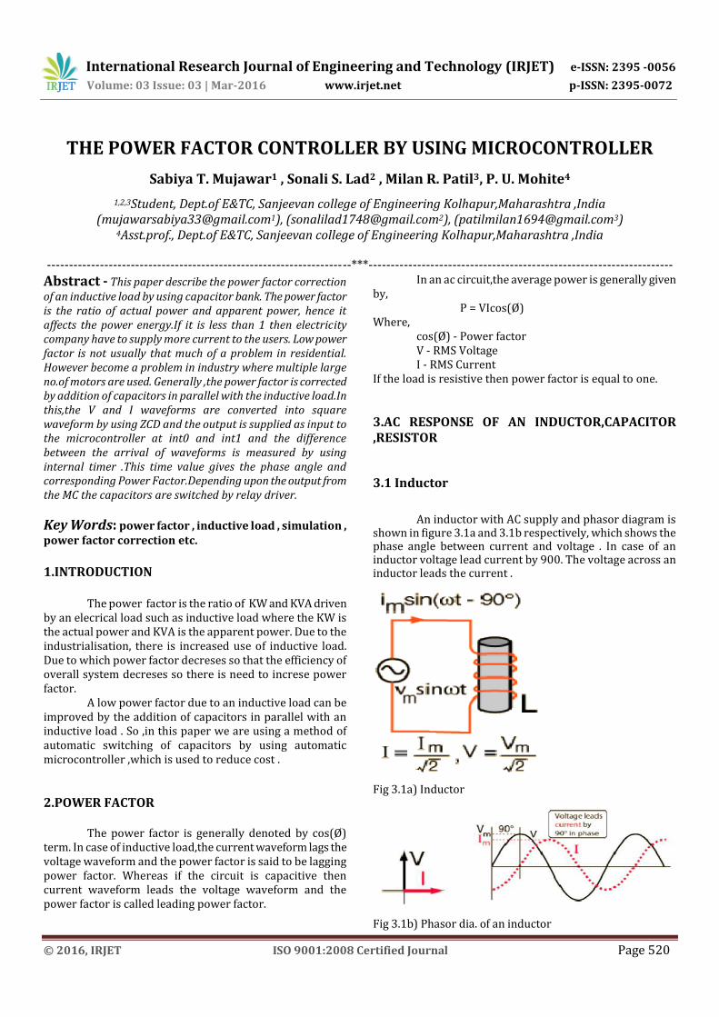
An inductor with AC supply and phasor diagram is shown in figure 3.1a and 3.1b respectively, which shows the phase angle between current and voltage . In case of an inductor voltage lead current by 900. The voltage across an inductor leads the current .
Fig 3.1a) Inductor
Fig 3.1b) Phasor dia. of an inductor

International Research Journal of Engineering and Technology (IRJET) e-ISSN: 2395 -0056
Volume: 03 Issue: 03 | Mar-2016 www.irjet.net p-ISSN: 2395-0072
© 2016, IRJET ISO 9001:2008 Certified Journal Page 521
3.2 Capacitor
A capacitor with AC supply and phasor diagram is shown in figure 3.2a and 3.2b respectively , which shows the phase angle between current and voltage . In case of capacitor voltage lags current by 900. The voltage across a capacitor lags the current .
Fig 3.2 a) Capacitor
Fig 3.2 b) Phasor dia.of capacitor
3.3 Resistor
A resistor with AC supply and phasor diagram is shown in figure 3.3a and 3.3b respectively, which shows the phase angle between voltage and current is 00. For ordinary currents and frequencies, the behavior of a resistor is that of a dissipative element which converts electrical energy into heat. It is independent of the direction of current flow and independent of the frequency. So we say that the AC impedance of a resistor is the same as its DC resistance.
Fig 3.3a) Resistor
Fig 3.3b) Phasor dia. of a resistor 4. BLOCK DIAGRAM
Fig 4. Block dia. Of PFC 4.1 Potential & Current Transformer These are basically step down transformer. The main function of the transformers is to step down voltage & current in a measurable value .And the output step down AC is given to the rectifier circuit .
4.2 Rectifier circuit The rectifier is nothing but the convertor . It converts the step down AC voltage into DC voltage . And the output is connected to the voltage regulator . 4.3 Voltage Regulator It converts the variable DC voltage into constant DC voltage and the output is given to the ADC block . Here IC 741 OP-AMP is used as a voltage regulator, which gives two DC voltages for the working of MC & LCD display panel. 4.4 Microcontroller It operates in an automatic power factor controller mode.
International Research Journal of Engineering and Technology (IRJET) e-ISSN: 2395 -0056
Volume: 03 Issue: 03 | Mar-2016 www.irjet.net p-ISSN: 2395-0072
© 2016, IRJET ISO 9001:2008 Certified Journal Page 522
4.5 ZCD It is nothing but the convertor . It converts sine wave into a square wave and the reference voltage in case of ZCD is set to the 0V . The output waveform of ZCD is gives when & in which direction the input voltage crosses 0V. 4.6 Relay & Relay Driver The relays are used to switch the capacitance value depending on the output of the MC.
5. MATHEMATICAL CALCULATION
The V and I waveforms converted into square waveforms by using zero crossing detector. The phase angle between the two waveform is calculated by using the following formula, Phase angle(Ø) = 3600 * f * Δt Where, f – Supply frequency Δt – Time gap between V and I waveforms Then the power factor is calculated by, PF = COS(Ø) Where, Ø – Phase angle 6. HARDWARE ANALYSIS
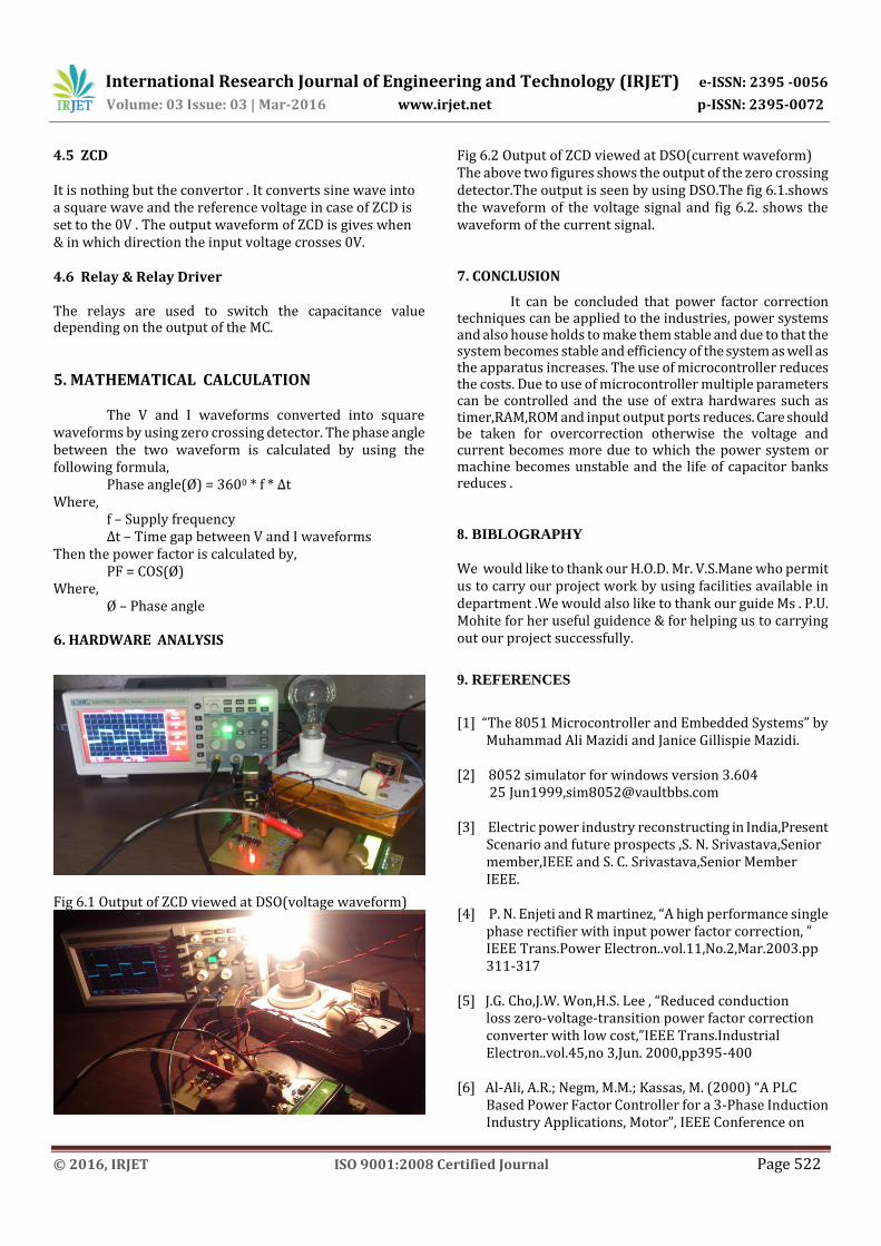
Fig 6.1 Output of ZCD viewed at DSO(voltage waveform)
Fig 6.2 Output of ZCD viewed at DSO(current waveform) The above two figures shows the output of the zero crossing detector.The output is seen by using DSO.The fig 6.1.shows the waveform of the voltage signal and fig 6.2. shows the waveform of the current signal. 7. CONCLUSION
It can be concluded that power factor correction techniques can be applied to the industries, power systems and also house holds to make them stable and due to that the system becomes stable and efficiency of the system as well as the apparatus increases. The use of microcontroller reduces the costs. Due to use of microcontroller multiple parameters can be controlled and the use of extra hardwares such as timer,RAM,ROM and input output ports reduces. Care should be taken for overcorrection otherwise the voltage and current becomes more due to which the power system or machine becomes unstable and the life of capacitor banks reduces .
8. BIBLOGRAPHY
We would like to thank our H.O.D. Mr. V.S.Mane who permit us to carry our project work by using facilities available in department .We would also like to thank our guide Ms . P.U. Mohite for her useful guidence & for helping us to carrying out our project successfully.
9. REFERENCES
[1] “The 8051 Microcontroller and Embedded Systems” by Muhammad Ali Mazidi and Janice Gillispie Mazidi. [2] 8052 simulator for windows version 3.604 25 Jun1999,[email protected] [3] Electric power industry reconstructing in India,Present Scenario and future prospects ,S. N. Srivastava,Senior member,IEEE and S. C. Srivastava,Senior Member IEEE. [4] P. N. Enjeti and R martinez, “A high performance single phase rectifier with input power factor correction, ” IEEE Trans.Power Electron..vol.11,No.2,Mar.2003.pp 311-317 [5] J.G. Cho,J.W. Won,H.S. Lee , “Reduced conduction loss zero-voltage-transition power factor correction converter with low cost,”IEEE Trans.Industrial Electron..vol.45,no 3,Jun. 2000,pp395-400 [6] Al-Ali, A.R.; Negm, M.M.; Kassas, M. (2000) “A PLC Based Power Factor Controller for a 3-Phase Induction Industry Applications, Motor”, IEEE Conference on

International Research Journal of Engineering and Technology (IRJET) e-ISSN: 2395 -0056
Volume: 03 Issue: 03 | Mar-2016 www.irjet.net p-ISSN: 2395-0072
© 2016, IRJET ISO 9001:2008 Certified Journal Page 523
Volume: 2, Pages: 1065-1072. [7] Andersen, G.K.; Klumpner, C.; Kjaer, S.B.; Blaabjerg, F.(2002) “A New Green Power Inverter for Fuel Cells”, IEEE Conference on Power Electronics Specialists, Volume: 2, Pages: 727–733. [8] Ayres, C.A.; Barbi, I. (1996) “CCM Operation Analysis of a Family of Converters for Power Recycling During the Burn-In Test of Synchronized UPSs”, IEEE Conference on Power Electronics Specialists, Volume: 2, Pages: 986-992. [9] Miller, M.; Buffin, A.; Carlsson, U. (1993), “High Frequency ZVS for High Power Rectifiers”, IEEE Conference on Telecommunications Energy, Volume: 1, Pages: 424–430. [10] Molina, M.G.; Mercado, P.E. (2006) “Control Design and Simulation of DSTATCOM with Energy Storage for Power Quality Improvements”, IEEE Conference and Exposition on Transmission & Distribution, Pages: 1-7 [11] Nalbant, M.K. (1990) “Power Factor Calculations and Measurements”, IEEE Conference on Applied Power Electronics, Pages: 543 –