the professional magazine fob electronics and …
TRANSCRIPT

THE PROFESSIONAL MAGAZINE FOB ELECTRONICS AND COMPUTER SERVIC NG
1E01'11011'1Servicinc & Technology June 1995
Video heads and related circuits
Setting up a test bench
10000 4209477 ****.emitieefit-*****30e*
11"1"1111.1111"11 11111"111IIOICI- 11111"1111111111Ill0 74470

mis
d --
is
,r-.
,
GJimAVS..°
ASA171°°°
vOCT°
Of."1111.
MEpBVpE
6'
1011614SIlY
00
r:r: 0.0
0
pgrAjN
."'0rIos
11-IWO-
0
roeNVUI
"If Only I Could..."
Only one instrumentprovides
you with everything
you need to analyzeand troubleshoot
camerasand
camcorders.So, whether
you'rejustgetting
started
or are a seasonedprofessional,
the exclusivedigital
analyzingtests ofthe CVA94
"VideoTracker"
will
help you betterservice
all :ypesofconsumer
camcorders.
it
3200 SencoreDrive.
SiouxFalls,
SouthDakota
Direct(605)
339-0100Fax (605) 339-0317
Call 1-800-SENCORE
and ask
how the CVA94will benefit
your
servicecenter.
We'll show you
what the CVA94can do for you
andprovideyou with business
buildingideas to help ensure
you
aprofitableyear.
Call 1-800-SENCORE.(736-2673)
pEt
00
it
Div Canacorder
AOPoint
1est
Procedure
Totheist100
Ca1t
r
erst
CIrcw(1)
ReiMCed
i

Contents
page 6
FEATURES6 Troubleshooting N ideo head
problemsBy Jurgen EwenThis feature contains ideas on howto troubleshoot common problemsthat you may encounter when deal-ing with video heads.
13 Clean up and repair that testequipmentBy Homer L. DavidsonAccidents as well as everyday wearand tear can cause test equipment tomalfunction. This article gives someideas on how to repair or replace oldpieces of test equipment.
19 Setting up a servicing benchBy The ES&T StaffThe service bench is the heart of anyservice center. In this article youwill learn the elements needed foran efficient test bench.
23 Recycling electronic devicesBy Dale C. ShakelfordA service center can save consider-able time, money and effort when itcomes to dealing with salvagedparts. In this article you will learn
ME PROFESSIONAL MAGA,
ELEGTIR011ieServicing & Ter[in-,1- :
olume 17, No. 6 June 1995
POT
ICI
0101
100
POT
F * 2200µF
A AD102 0103
T101
how to effectively and profitablyrecycle electronic devices.
26 More ways to diversify yourbusinessBr Ron JohnsonIf you're looking to expand yourhorizons, you may just have totransfer your current expertise intoa new area. Author Ron Johnsonexplains how a servicer can expandinto the field of automotive testequipment.
43 Computer maintenance anddiagnostics using MS-DOS 6.0By David PresnellIn this article author David Presnellgives readers some tips about howto use the utilities in MS-DOS 6.0to clean up hard drives before prob-lems arise, and how to handle themif they do.
48 Understanding and optimizingPC memoryBy Steven J. BigelowThis article explains PC memoryand shows you how to configure sys-tem startup files to free up as muchconventional memory as possible.
DEPARTMENTS2 Editorial
4 News
18 ES&T Calendar of Events
30 Test Your Electronics Knowledge
33 Profax
47 Products
56 Computer CornerProfitable preventive maintenanceand surge protection.
58 Video CornerServicing remote control.
60 What Do You Know AboutElectronics?Motor speed control and load lines.
63 Literature
64 Business CornerLeadership.
66 Books
70 Classified/Readers' Exchange
72 Advertisers' Index
ON THE COVERTest equipment manufacturers provideservice technicians with modern sophis-ticated products to make diagnosingproblems in consumer electronics easi-er, faster and more accurate. But eventhe best piece of test equipment needssome attention now and again to keep itlooking and working like new. (Photocourtesy of Sencore)
June 1995 Electronic Servicing & Technology 1

Editorial
Sharpening and enhancingservicing skills
This issue of Electronic Servicing &Technology includes two articles thatare specifically designed to providesome useful information on thetest/diagnostic process: "Setting up atest bench," and "Clean up and repairthat test equipment." The point of thetwo articles taken together is that thetechnician's bench position is the placewhere the work is done, and it is thatwork that brings in the money to the ser-vice center. Because of this, attentionshould be paid so that the bench posi-tion is efficient, and that valuable testequipment is occasionally treated tosome degree of maintenance.
Not discussed in the articles is the im-portance of the training and skills of theindividual who will be making judg-ments, and taking corrective actions asa result of his interpretation of the read-ings that the test instruments give him:the technician.
Of course, we all recognize that thebest test equipment is useless without ahuman mind to determine what pointsin the circuits of the product should beprobed, and to interpret the data that theinstruments display. But do we some-times forget that information in thatmind can decay over time, just as thecircuits in the test instrument. And justas important, advances in the technolo-gy in the test equipment calls foradvances in the skill of the technicianusing it.
Honing the skillsSome of the most successful service
centers involved in consumer electron-ics servicing do in fact appreciate theimportance of keeping the mind of thetechnician as sharp as the technologyembodied in the latest test equipment,but it's easy to become complacent and
to forget that the skills and knowledgeof the best technicians were hard wonand need to be constantly honed.
There are a number of ways to keepthose technical skills up to date. Testequipment manufacturers offer techni-cal training in places across the country.Many of these manufacturers also offerbooks, pamphlets and video tapes withdetailed instructions on understandingand using their test equipment.
Many technical book publishersoffer books that describe in detail someof the new technology offered in the lat-est test equipment and provide instruc-tions and suggestions on getting themost out of them.
Conventions offer skillsbuilding opportunities
Some associations also provide train-ing seminars that help service managersand technicians hone their skills. Twogroups will be holding meetings atwhich technical training will be offeredto interested parties.
In July, the Electronics TechniciansAssociation, International (ETA) willhold its 1995 conference in PhiladelphiaJuly 20, 21 and 22. The location of thisevent, called "Building America'sConcourse - East," is the PhiladelphiaWireless Technical School, 1533 PineStreet, in Philadelphia. Headquartershotel for the event is the Holiday InnMidtown at 13th and Walnut.
Several classes that will provide col-lege credit to participants are a Satellite,Antenna and MATV (SAM) school,Business Management School (BMS),and Electronics Technician (ET)Classes. Anyone interested may receivemore detailed information by calling317-653-4301, or by faxing an infor-mation request to 317- 653-8262,
or write to ETA, 602 N. Jackson,Greencastle, IN 46135.
The National Electronics ServiceDealers Association and the Interna-tional Society of Certified ElectronicsTechnicians (NESDA/ISCET) will holdtheir annual convention, the NationalProfessional Electronics Conventionand Trade Show, at the Hyatt Regency,Crystal City, Arlington, VA, from July31 through August 5, 1995.
The events that will take place in con-junction with this conference are man-agement seminars, technical seminars,dealer/manufacturer meetings, an in-structors conference and more.
For further information on NPEC, call817-921-9061, or fax at 817-921-3741,or write to NPEC, 2708 W. Berry St.,Fort Worth, TX 76109.
You will be welcome
Some readers who are not membersof one of these groups have expressedthe concern that they might not be wel-come at one of these meetings. Both ofthese groups have made it very clear thatthey welcome anyone associated in anyway with electronics servicing to attendthese events.
I have personally attended many ofthe conventions of these organizationsand have found the members to beuncommonly friendly, outgoing andwelcoming to anyone who cares to asso-ciate with them. So if you're looking fora way to sharpen up some of your skills,and you're going to be in the MiddleAtlantic region this summer, it would beto your advantage to take in one or bothof these events.
2 Electronic Servicing & Technology June 1995

IEEE Ev011 ZONAL MAGAZINE FOIL ELECTRONICS AND COMPUTER SERVICING
ELOOTINIIIMServicing & TechnologyElectronic Servicing & Technology is edited for servic-ing professionals who service consumer electronicsequipment. This includes service technicians, field ser-vice personnel and avid servicing enthusiasts who repair
and maintain audio, video, computer and other con-sumer electronics equipment.
EDITORIALNils Conrad Persson, EditorKirstie A. Wickham, Associate EditorRichard S. Moseson, NW2L, On -Line Coordinator
CONSULTING EDITORSHomer L.Davidson, TV Servicing ConsultantVictor Meeldijk, Components ConsultantJohn E. Shepler, Audio ConsultantSam Wilson, Electronics Theory Consultant
PRODUCTIONElizabeth Ryan, Art DirectorBarbara Terzo, Associate Art DirectorSusan Reale, Assistant Art DirectorEdmond Pesonen, Electronic Composition Mgr.Dorothy Kehrwieder, Production ManagerEmily Kreutz, Assistant Production ManagerPat Le Blanc, Phototypographer
BUSINESSRichard A. Ross, PublisherJohn Dorr, General ManagerFrank V. Fuzia, ControllerSimon Schatzmann, Circulation DirectorCatherine Ross, Circulation ManagerMelissa Nitschke, Operations ManagerCarol Licata, Data ProcessingDenise Pyne, Customer Service
SALES OFFICEElectronic Servicing & Technology76 N. Broadway, Hicksville, NY 11801516-681-2922; FAX 516-681-2926
Diane G. Klusner, Director of AdvertisingEmily Kreutz, Sales Assistant
EDITORIAL CORRESPONDENCE:P.O. Box 12487Overland Park, KS 66212913-492-4857
ElecIllackService
NESDAMember. Electronic Servicing
Dealers Association
Electronic Servicing & Technology (ISSN 0278-9922) ispublished 13 times a year by CO Communications, Inc. 76N. Broadway, Hicksville, NY 11801. Telephone (516) 681-2922. Second class postage paid at Hicksville, NY and addi-tional offices. Subscription prices (payable in US dollarsonly): Domestic-one year $24.75, two years $45. Foreigncountries-one year $30.75, two years $57. Entire con-tents copyright 1995 by CO Communications, Inc.
Electronic Servicing & Technology or CO Communica-tions, Inc. assumes no responsibility for unsolicited man-uscripts. Allow six weeks for delivery of first issue and forchange of address. Printed in the United States ofAmerica.
Postmaster: Please send change of address notice toElectronic Servicing & Technology, 76 N. Broadway.Hicksville, NY 11801.
CO Communications, Inc. is publisher of CO The RadioAmateur's Journal, Popular Communications, Micro -Computer Journal, CO Radio Amateur (Spanish CO). COAmateur Radio Equipment Buyer's Guide, CO AmateurRadio Beginner's Buyer's Guide. Popular Communica-tionsCommunications Guide, and Electronic Servicing &
Technology.
Measure It All!The DNIMACR Meter/
Frequency Counter. All in One.Troubleshoot down to thecompcnent level - anycompcnent! Verify poorly
marked parts, test for toler-ances and damage. Wavetek'snew DM27XT is not only a full -function DIVM, but alsoincludes conplete inductance,capacitance and frequencymeasurement capabilities.
Wide LCR range:10 S2 to 2000M1210 pF to MOO pF100 pH to 20 H
Autoranging frequencymeter 10 Hz to 20 MHz
Ac and dc current to 20 A
Logic test diode test, maxreading hold, continuitybeeper, input warningbeeper, fused inputprotection, battery saver
Consolidate your test benchone meter that does it all -Wavetek's high -performing,full -function XT Series DMM.It's all in one compact, rugged,field -ready package with a big0.7 -inch, 31/2 -digit display.Insulated probes and alligatorclip leads are included, andthere is a huge selection ofaccessories, ncluding current,rf and liV pubes, temperatureconverters, holsters, and cases.Ask for Wavaek DMMs. They'rethe meters to pick when youhave things to fix.
AAto
$11995Other XT times DMMs from $89.95
U.S.A.: (619)279-2200Europe: (44/243) 531323Asia Pacific:(852)865-1903
oi,$)t Wasctek arpo.non
--,..01111111111141Memsmon,...401...,
-.alb.-
ncAc
In 0 mmVVH H
I 11 yA mA A-mr- kHz MHz
9AT CI ictlIAC1nF
LOGIC -04- 1)) MAX
H 2C
2
200m -
20ms
2m
. .4-
..,
T1 L
.CMOs
WOOM
20M
2M LI 200k
2C k
WAVS-ra <
204.1rc
I1/YA /A,
1000750
200 V20
2200m
A 20011
20m 2CA 2m
10 ; 20n
20µ
'k 200 2000µ
200µ
2n
WAve-reK
Circle (44) on Reply Cud 3

NewsCQ Publications featured in GEnie
electronic magazine.CQ Communications, Inc. is in the
"Vendor Spotlight" in the premiere issueof the GEnie Radio & Electronics Round-table's online magazine. All of CQ's mag-azines are featured, including CQ The Ra-dio Amateur's Journal, Popular Commu-nications, Communications Quarterly,Electronic Servicing & Technology andMicroComputer Journal.
The online magazine is "downloaded,"or copied electronically, from GEnie tothe user's home computer and is thenviewed on the computer screen. It is notdesigned to be printed on paper. Featuresinclude ham radio news reprinted fromthe "ARRL Letter" and a text version of"Newsline," plus articles and a monthly"Vendor Spotlight."
Readers accessing the "Vendor Spot-light" in the premiere issue will see the CQlogo and a variety of buttons on theirscreen. There is one button for each mag-azine plus one labled "About CQ Commu-nications, Inc." and another titled "FreeOffer." Selecting any of the magazine but-tons brings up a screen containing a briefdescription of the publication, along withsubscription information. Likewise,"About CQ Communications" provides anoverview of the company; and the "FreeOffer" button provides details of the auto-mated system by which GEnie users mayrequest sample copies of CQ and PopularCommunications.
Responding to the tremendous growthof online services and their growing pop-ularity among the readers of its maga-zines, CQ Communications has estab-lished feedback areas and other readerservices on GEnie and America Online.CQ staffers are also active informally onCompuServe and the Internet.
EIA/CEG endorses legislationensuring consumer electronic
products competitionThe Electronic Industries Association/
Consumer Electronics Group's (EIACEG) Board of Directors endorsed thepassage of federal legislation to ensurecompetitive availability of consumerelectronics products. In order to avoid a'90's version of the black phone in everyhome, steps must be taken now which will
let consumers purchase their home equip-ment from the vendor of their choice.With this goal in mind, Rep. Thomas JBliley (R -VA and Chairman of theHouse's Commerce Committee) and RepEdward J. Markey (D- MA) introducedHR1275 on March 16, 1995, whichdirects the Federal CommunicationsCommission (FCC) to adopt regulationsthat assure the competitive availability ofconverter boxes, interactive communica-tions devices and other consumer premis-es equipment from manufacturers, retail-ers and other vendors not affiliated withany telecommunications system operator.
"With proprietary equipment from net-work and service providers controllingaccess to telecommunications networks,consumers would not have the optionsavailable to them which now can be foundin the telecommunications marketplace,"said Gary J. Shapiro, group vice presidentof ETA's Consumer Electronics Group."Competitive availability of consumerelectronics products will allow 'plug andplay' by consumers wishing to access thegrand array of new communications,information and entertainment services tobe delivered over the developing infor-mation highway."
"For years, consumers could not choosetheir own telephones," added Shapiro."Once the Bell monopoly on telephoneswas lifted, manufacturers entered the mar-ket and gave us higher quality, more fea-ture -rich and more affordable telephonesand telephone -related products such as faxmachines, answering machines and com-puter accessories. This same type of mo-nopoly could be propagated in the cable,satellite, fiber optic and other industrieswhich will make up parts of the growingNational Information Infrastructure (NII)."
A competitive retail market for accessdevices will mean new features, betterquality and lower prices for consumers.With hardware built into products oravailable separately in boxes at retail,capital would be freed for the service pro-vider to invest in extending and improv-ing service networks and programming.Once legislative language similar to HR -1275 is adopted, consumer electronicsmanufacturers will be able to drive tech-nological innovations and spur develop-ment of new products and features.
EIA is the 71 -year -old trade associationrepresenting the electronics industry.ETA's Consumer Electronics Group rep-resents U. S. manufacturers of productssuch as audio, video, home office andhome automation products, mobile elec-tronics, multimedia and accessories.
Public awareness of RBDS increasingPublic awareness of the Radio Broad-
cast Data System has grown from 10 per-cent of adult consumers to 16 percent inthe last 12 months, according to a surveycommissioned by the Electronic Indus-tries Association's Consumer ElectronicsGroup (EIA/CEG). When asked if theywould like to own RBDS audio equip-ment, 20 percent said they were veryinterested, compared with 18 percent in1994. Of those expressing interest inowning RBDS, 22 percent said theywould like to purchase it as an option ona new car. Twenty percent would like toown it as part of their home systems.
"Clearly, more consumers are becom-ing aware of RBDS and its benefits," saidGary Shapiro, group vice president ofE1A's Consumer Electronics Group. "Asawareness increases, interest in RBDSfeatures, and in ownership increases.They remember what they've seen andread, and the result is that RBDS popu-larity is on the upswing."
Overall consumer interest in specificRBDS features also rose from a previoussurvey. According to the survey, what theRBDS features respondents want mostare station call letters, station format andadvertising to be displayed on their equip-ment. Some RBDS features saw largeincreases in interest, including station callletter and format display, as well as built-in messaging and paging.
Local stations are first in U.S. toparticipate in EIA campaign
The Electronic Industries Association'sConsumer Electronics Group (EIA/ CEG)announces that Philadelphia stationsWUSL, WIOQ, WWDB, WMGK andWXTU have agreed to broadcast RBDS aspart of a national campaign to equip 500FM radio stations with RBDS. All the sta-tions are expected to begin broadcasts byMay 15. The addition of these stationsusing RBDS would bring to 14 the total
4 Electronic Servicing & Technology June 1995

number of RBDS stations serving thePhiladelphia metro area. In addition, anumber of additional Philadelphia FMradio stations are expected to jump on thisbandwagon.
"It's important to be announcing thesedevelopments the day we publicly kickoff the RBDS campaign," said Gary J.Shapiro, group vice president of EIA/CEG. "We're serious about popularizingRBDS and making it available to the pub-lic, and this is the best way to prove it."
Of the five stations committed to add-ing RBDS systems to date, WUSL, on fre-quency 98.9, plays urban contemporary,and WIOQ, located at 102.1, plays urbancontemporary music. WWDB, at 96.5 onthe dial, is Philadelphia's most populartalk station and WMGK, 102.9, plays'70s oldies and WXRU, at 92.5, is a coun-try music station. Currently stationsWPLY, WFLN, WHYY, WMMR, WRIIand WXPN broadcast RBDS.
Combined, the five stations have 23.5percent marketshare of the Philadelphiaradio audience, based on Aribtron fig-ures. These stations, with the six that pre-viously added RBDS, will raise RBDSbroadcast market penetration in Phila-delphia to 36.3 percent.
"In exchange for the equipment pro-vided by the EIA, the stations will air adsor announcements to educate listenersabout RBDS and promote the use ofRBDS radios," said Shapiro. The ads willair once the RBDS systems are up andrunning at the stations. RBDS is an excit-ing and important new technology notonly for consumers but for FM broad-casters as well. RBDS allows for a con-ventional FM radio broadcast to carrydigital data "piggy- back" on an inaudi-ble subcarrier. These computer style bitsand bytes of information offer a vastpotential of practical benefits for both lis-teners and broadcasters.
EIA to enter 25 largest marketsintroducing RBDS technology
After launching a national program inPhiladelphia to equip 500 FM radio sta-tions in the nation's 25 largest metropol-itan areas with the Radio Broadcast DataSystem (RBDS), the Electronic Indus-tries Association's Consumer ElectronicsGroup (EIA/CEG) announced that it
(Continued on page 69)
p
Now there is a fast, safe, effectiveway to give contaminants thebrush-off. The new BrushCleanTMSystem combines powerfulsolvents with the gentle scrubbingaction of a brush. Use three ways:spot clean economically with thebrush, flush under SMDs with theextension tube, or clean largeareas with the spray nozzle.Three powerful tools - onecon venie
Now available.
Ova,
"11111lik"1,rt,- -
CFC Free Flux -Off 2000Cleaning system quickly andcompletely removes R, RMA,RA and synthetic flux.
Flux-Ofr IIProprietary alcohol blendcleaning system removeswater soluble and all otherfluxes quickly.
CFC Free Electro-Wash® mooFast drying one step cleaningand degreasing system safefor most plastics.
Pow-R-WashTMHighly effective nonflammableprecision cleaning system safefor use on metals and mostplastics,
The BrushClean System features thenew All -Way Spray Valve that spraysin anydirection, even upside down!
Chemtronics®(The So u ons ource.
Facts
Name
Company
Phone Fax
Street Address
CI YES! Please send my FREE copy of ChemFacts-a comprehensive guide for selecting the right cleaning productsfor electrical and electronics service, rework and repair.
Title
City State Zip
rrlto
CM
Which describes your business: 0 Production 0 Service and Repair Cl OtherNumber of technicians using the type of cleaning product in this adWhich best describes your role: Recommend/specify products CI Purchase D Other
CALL 1-800-645-5244
FAX TPAGE 404-423-0748
Mail to:Chemtronics, Inc.8125 Cobb Center Dr.Kennesaw, GA 30144
Circle (21) on Reply CardJune 199E Electronic Servicing & Technology 5

Troubleshooting video headproblemsBy Jurgen Ewert
All home video recording systems madetoday function the same way, and the ba-sic signal flow of these systems is verysimilar. During the recording process, theluminance and the sync signals are con-verted into an FM signal. It is not practi-cal to record the video signal, with its fre-quency bandwidth that ranges from 60Hzto 4.2MHz, directly on magnetic tape.The color signal is separated from thevideo signal, and converted down to a fre-quency band below the FM signal andthen it is superimposed on the FM signal.Figure 1 shows the spectrum of the re-cording signals in a video recorder.
Recording the video signal
A basic block diagram of the video sig-nal flow in a VCR is shown in Figure 2.The video signal is fed into the recordingsection, where it is split into luminanceand chrominance components. To avoidinterference between the luminance sig-nal and the FM recording signal, the band-width of the luminance signal is limitedto about 3MHz and the carrier frequencyfor the FM is placed above the luminancefrequencies. Since the highest frequencyof the luminance signal after the low passfilter (Y -LP) is about 3MHz, there is nocolor signal left in this signal. Then, theluminance signal is put through a pre -emphasis circuit (PEEM) and a white lim-iter. The pre -emphasis enhances the high-er frequencies of the luminance signal toprovide a better overall signal-to-noiseratio. The white limiter (WH-L) limits(clips) the amplitude of the luminancesignal to avoid overloading of the fre-quency modulator (FM -M).
The chrominance signal is separated ina bandpass or a comb filter (C -BP) anddownconverted (C -C) into the color un-der signal. A low pass filter (C -LP) re-moves unwanted frequencies from theconverted signal. Both signals are mixedback together and fed through the record-
Ewert is an independent consumer electronics servicingtechnician.
FREQUENCY RANGE OF Y - FM - AND FU - SIGNAL
COLOR UNDERSIGNAL
629KHZ
FREQUENCY DEVIATION
3.4MHZ
TIME
T
4.4MHZ
LUMINANCE SIGNAL
FREQUENCY
F
Figure 1. Spectrum of the recording signal
ing amp, record/playback switch (R/PSW) and the rotating transformer into thevideo heads.
The FM signal operates for the colorunder signal the way the bias signal doesin magnetic audio recorders. This is bene-ficial because of the quadrature modula-tion that is used for the chrominance com-ponent. This type of modulation makes itnecessary to record the amplitude valuesof the color signal. To avoid visible inter-ference caused by the color under signal,its frequencies were carefully chosen.The amplitude of the color under compo-nent that is added to the FM signal is onlyabout 10% of the total amplitude.
Playback of the video signal
In playback mode, the mixture of theluminance, FM, and color under signals
passes from the video heads via the rotat-ing transformer and record/playbackswitch into the inputs of the head amps.There is one head amp for each head (HA -A and HA -B). The head switch (H -SW)connects the head amp output of the headthat is in contact with the tape to the play-back circuits. A high pass filter, (L -HP)filters out the luminance FM signal.
Drop outs in the playback signal arereplaced by a stored replacement signalin a dropout compensator (DOC) to pre-vent noise getting into the playback pic-ture. The frequency demodulator (FM -D)demodulates the FM signal. The originalluminance signal is present at the outputof the de -emphasis circuit.
The color under signal is separatedfrom the FM signal in a low pass filter(CULP). Then it is converted back to the
6 Electronic Servicing & Technology June 1995

TP1
TP2 Y - FM + CU
H - SWFV/2
HA - A HA - B
t I
ERASE HEAD
TAPESUPPLY
O
SW
A
171-1FM + CU
Y - FM
R - A
1
4 C U
A/C HEAD
CI CAPSTANPINCH
ROLLER
HEAD DRUMROTARY TRANSFORMER
VIDEO CASSETTE
6TAPE
TAKEUP
0
L - HP DOC FM - D DEEM
CULP C - UC C - BP
PLAYBACK
FM M WH - L PEEM Y - LF
C - LP
LC - C C - BP
RECORD
LUM
- MIX
CHROM
- - -Ow VIDEOOUTPUT
41111 VIDEOINPUT
Figure 2. Video block diagram
original frequency hand (C-UC). Thechrominance signal passes through aband pass filter, (C -BP) into a mixerwhere it is combined with the luminance
signal into a complete color video signal.Home video recorders use two video
heads on a rotating drum to record, andplayback the mix of luminance FM and
color under signal. The advantage of twohead systems is the possibility of simplertape loading mechanisms. In some VCRs,four video heads are used to provide opti-
VCR REPAIR? A BETTER WAY!Do BETTER and FASTER Repairs with the problem solving ability of the FOUR differentTENTEL gauges...MECHANICAL PROBLEMS account for most VCR problems;TAPE EATING, EDGE DAMAGE, and VIDEO signal problems.
TENTEL offers the WORLD's MOST Powerful, Universal, easy touse TEST equipment fortape tension, guide height, torques, videohead wear, spindle height, and other critical measi. rements.
If you've already invested money in scopes and other electronic testequipment, but you're still just guessing for the many critical me- -chanical tests and set-ups (the majority of VCR problems), havn't yoj SII;11struggled long enough! Our 100% Money back guarantee assuresthat you will be ecstatic with these instruments. TENTEL also offersa complete VIDEO TRAINING PROGRAM, showing machine standards, tolerances, and measur-ing methods for 28 different mechanical tests. Call NOW for more information....4.)°ENTEL8 4475 GOLDEN FOOTHILL PKWY.
EL DORADO HILLS, CA 95762 800-538-6894 / 916-939-400524 hour FAX line: (9161939-4114
Circle (43) on Reply Card
June 1995 Electronic Servicing & Technology 7

SWEEPSTAKESWin A VC93 All Format VCR Analyzer!
Isolate video fromservo defects!
Pinpoint capstanand cylinderservo defects!
Eliminate the guess-work associated withreplacing video or audioHi-Fi heads; before youorder the new heads!
Troubleshoot all VCR formats with thesame procedures and confidence every time!
ZZ'
To win the VC93, simply respond through the reader service# atthe bottom of this ad. We'll enter your name for the Aug. 31, 1995
drawing and send you more information on the VC93.No purchase necessary. Void where prohibi
Frustrated With Servicing The Tough Dog
VCRs and Camcorders?
Sencore can help . . .all you have to do is call!
3200 Sencore Drive, Sioux Falls, SD 57107 1-too-SENCORE (736-2673)Direct: (605) 339-0100 Fax: (605) 339-0317
Figure 3. Head drum with four video heads
mal conditions for the different tapespeeds. (Figure 3)
Troubleshooting N ideo head
related problems
The video heads, and the tape -headsystem, are the weakest parts of the videosignal path. The video heads in a VCR aresubject to wear and tear because the rela-tive velocity between tape and heads isquite high.
To get a good transfer of the magneticfield between the tape and the heads, thetape -head contact needs to be very close.The gap of the video heads is accuratelydesigned for the frequencies that are usedin the specific video recording system.
The playback signal that is generatedby the video heads is in the microvoltrange. If the head gap changes greatlybecause of head wear, the amplitude ofthe playback signal will be much less. Ifthe amplitude of the playback signal islow, the FM demodulator at the end of theplayback circuitry will put out noise.
Video head and tape -head contact re-lated problems always appear in the play-back picture as snow; that is the noise pro-duced by the head amplifier and the FMdemodulator. So if there is no picture andno noise the problem is not the heads. Thisdoes not apply to VCRs with video mute
Circle (38) on Reply Card
8 Electronic Servicing & Technology June 1995

circuits. These circuits, often found inVCRs with on screen display (OSD), usu-ally place a blue screen on the TV picturetube if the playback signal is missing ornoisy.
Clean the heads firstBefore checking the playback signal at
the output of the head amplifier, it is usu-ally a good approach to clean the videoheads. This work should be done careful-ly because it is easy to break the tip of avideo head. The heads are made out offerrite (a ceramic material) and the tips ofthe heads are very thin.
It is very important never to move thecleaning tool in a vertical direction. Toavoid any vertical movement betweencleaning tool and head tip it is best to pushand hold a lint -free chamois, dampenedwith alcohol or a cleaning fluid, to the up-per drum assembly. Then, rotate the upperdrum by hand so that the heads touch thechamois. I have used a number of differ-ent cleaning tools and had very good re-sults with the one shown in Figure 4. Aftercleaning the heads it is important to cleanthe capstan, pinch roller, and the otherparts of the tape path.
The use of cleaning tapes is often notenough. These tapes are good for a clean-ing at the VCR user's home. VCRs withautomatic head cleaning provide a simi-lar cleaning action after each stop of thetape. In 90 to 95 percent of all cases, clean-ing the heads solves the problem. It doesnot take much grime to block the flow ofthe magnetic field to the heads. If theproblem is not solved after the first clean-ing, perform the head -cleaning procedureagain. It happened to me a few times, that
Figure 4. Cleaning the video heads
VIDEO TRACK WIDTHAZIMUTHHEAD DRUM DIAMETERRELATIVE HEAD/TAPE VELOCITYTAPE SPEEDSPLPEPROTATION OF HEAD DRUMFM DEVIATIONCOLOR UNDER CARRIER
58 tim+/- 6 deg62 mm5.8 m/s
1-5/16ips (33.35 mm/s)21/32 ips (16.67 mm/s)7/16 ips (11.12 mm/s)30rps3.4MHz to 4.4 Mhz
629kHz
Table 1. Tedinical data for the VHS system (NTSC)
the dirt on the heads was so sticky that Ineeded to clean the heads twice. Some-times you can see a little improvement inthe picture after each cleaning.
If cleaning does not solve the problemIf you have carefully cleaned the heads
and there is still noise in the picture, thenthe problem could be caused by the videoheads or the tape path. Usually, you candetermine whether the cause is the tapepath or a head related problem by watch-ing the picture on the screen. If the pic-ture shows horizontal stripes with noise,check the tape path for problems. Hori-zontal noise stripes occur if the heads can-not scan the whole video track.
Sometimes the heads cross a few tracksor just get out of the track. Check thetracking control first. Some people forgetto reset the tracking control after watch-ing a bad rental tape. If the tracking con-trol knob is set to the center position,watch how the tape runs through the ma-chine. Sometimes, the guide posts are
loose or the tape slips through pinch rollerand capstan. It is very important to tryplaying several different tapes when trou-bleshooting these problems.
A bad video cassette can cause thesesymptoms. If there is something wrongwith the heads, the picture shows noisefrom top to the bottom. In most cases, thepicture is still visible but there is a hazeof snow (Figure 5). If you see a picturelike this, put the probe of the oscilloscopeon the output of the head amps (TP1 inFigure 2). You will probably see an imagelike the one shown in Figure 6.
Connect one channel of the oscillo-scope to the 30Hz head -switching signalto synchronize the oscilloscope. This wayyou will get a steady image on the screenof your oscilloscope. Typically, all theheads in a VCR do not wear out at exact-ly at the same time. So one of the headsignals is mostly still present. It is not pos-sible to check the head signals directly atthe heads with the test equipment avail-able in an average service center. There -
Figure 5. Playback picture with one bad video head
June 1995 Electronic Servicing & Technology

566 aunp Aboioutoai 6uppues oiuoaloal3 0
sisod do-aNe) pue Aiddns to luemsnrpedr-limo) Jelle - wrap meu ylinn (c13) Indino dwe peak og ain6!A
leu6is isaq 101palsn!pe 6uppeThwnip mau llinn (d3) lndlno dwe peak qg ain6U
uoipsod Jawao Litwawisnfpe ampeil-wrup mau qi!mt (ds)Indino dwe peak eg airiBu
K see 01 CI .,"11
8.2)131011
*MO
214L1 '6S V7/Ise061111 to
0441u d3 -In!!
ANSVO Inv
wnip mau ql!m (ds)indino dwe peak 'L am6!A
(pooh speau qloq) d3 ui pubis dwe peak .qg ain6!d
(Peal -I peq) dS ui leuEqs lndlno dwe peed eg ainBIA

fore, it is not easy to find out if the headsare bad, or if the trouble spot is the rotat-ing transformer, the head amplifier or justa bad connection.
Narrowing down the problemBefore you order a new head drum you
can perform a few tests to narrow theproblem down.
Check the inductance of the videoheads using an inexpensive head testers.The inductance of a video head decreas-es if the head wears out, because the headgap gets wider. It is necessary to know theinductance of the good head for this testto be able to tell if the inductance is cor-rect or if it is too low.
Test the head amplifier by running theVCR in playback mode with no tape (usea test jig), and feed a 3.5MHz, 50pV sig-nal into the inputs. You will see a signalat the output if the head amp is in goodworking condition.
Feed a 3.5MHz, 20mV signal into therotating transformer at the head connec-tions and check the signal at the trans-former output (head amp input) with anoscilloscope. The signal at the output ofthe transformer should be more than at theinput. In most cases you will see a step upratio of about 1:2.
Use a head protrusion gauge to phys-ically measure the amount of the headactually remaining.
If available, use special test equipmentfor testing the heads, head amps and rotat-ing transformer. These test sets providean FM signal to substitute the head signaland you can inject the signals stage afterstage to locate the faulty part of this sec-tion in a VCR. If your business is doingwell and grows, it might be worth look-ing at one of these VCR testers to speedup repairs and increase efficiency.
Some real world head problemsMy customer complained that his Pan-
asonic VCR, Model PV -4760, showed anoisy playback picture when he tried toplay tapes recorded on other VCRs. Thetracking adjustment did not make a dif-ference in the picture.
When I checked the VCR I playedtapes at different speeds. Playing back atape in standard play (SP) caused a noisypicture (Figure 5). When I played a tapein extended play (EP) the picture was fine.So my customer obviously recorded all
his own tapes at the slowest speed. Rentaltapes come only in SP.
This VCR was a four -head machine.Evidently there was something wrongwith the SP signal path or the SP heads. Icleaned the video heads carefully but theproblem remained.
Because there was noise in the picture,I checked the head amp output with theoscilloscope. The results for playback inSP and EP are shown in Figures 6a and6b. I suspected one of the SP heads, butto make sure that there was nothing elsewrong I checked the rotating transformerand the head amps. Both were good.
I checked the inductance of the headsusing an LCR meter. At two heads I mea-sured 3.8pH and 3.7pH but the other pairshowed only 2.7pH and 1.9pH. This wasa strong indication that one pair of theheads was worn out.
When I received the new head drum, Ichecked the inductance of all four headsand measured from 3.7pH to 4.0pH on allof them. After replacing the head drum, Ichecked the signal at the head amp out-put. In SP mode, the output signal lookedperfect (Figure 7). The signal at the slowspeed (EP) did not look too good (Figure8a). It improved after I adjusted the track-
ing control (Figure 8b).Something was not right with the tape
path. After a little touch up adjustment ofthe supply and take-up posts the signallooked fine (Figure 8c) and the VCRworked like new.
An unusual video head repairI encountered a difficult problem on
another VCR that had a bad video head.I was unable to remove the upper drum.I tried to pull very hard but it wouldn'tcome loose. Then I used my Swiss Armyknife to try to pry apart the gap betweenlower and upper drum - nothing moved.
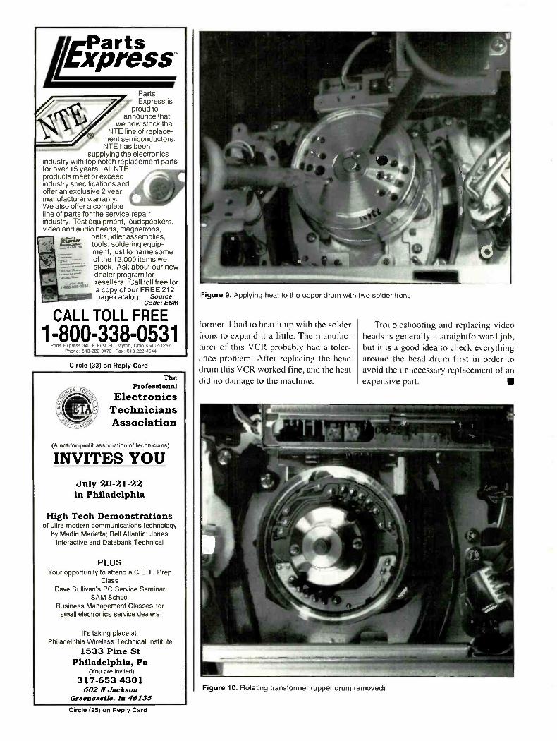
I remembered the old days when Iworked on my own car, a real `Trabant'.If I took the engine apart, it was neces-sary to heat up some parts to expand thediameter of the part in order to slide it off.It occurred to me that the same principlemight apply in this case, so I plugged mytwo soldering irons in and stuck the sol-der tips into the holes of the upper drumas shown in Figure 9. After approximate-ly a minute I was able to slide the upperdrum off. (Figure 10)
One of the heads on this drum was badso I ordered a new one. The new drumwould not slide onto the rotating trans -
VHS Repair Made Easy.Learn how to locate and solve VHS repair
dilemmcs wiih the latest Sony trainingtape release. This tape is loaded
with practical ways to locate andsolve VHS repair problems
using Sony's VHS II chassis.Operation, typical problems,
and troubleshooting arediscussed to give you a fast andeasy approach to VHS servicing.
7--1 YES, please send me VHS Troubleshooting IT-VHSTROU -9) in VHS for $55.00including shipping & handling. Please include applicable sales tax.
Please send me more information about Sony's videotape library.
Please charge my purchase to:
Mastercard -Visa- DiscoverCord # Exp Date__SignaturePhone #
NameCompanyStreetCity State Zip Code_Sorry, no C.C.D.'s. Allow two weeks for delivery.Pro, and availability subject to change.
Or Make check or money orderpayable to Sony ServiceCompany and mail completedform to:
Sony National Parts CenterATTN: Publications Dept.P.O. Box 20407Kansas City, MO 64195-0407
SONYCircle (39) on Reply .7.ard
hmPartsFXpreSSPartsExpress is
proud toannounce that
we now stock theNTE line of replace-
ment semiconductors.NTE has been
supplying the electronicsindustry with top notch replacement partsfor over 15 years. All NTEproducts meet or exceedindustry specifications andoffer an exclusive 2 yearmanufacturer warranty.We also offer a completeline of parts for the service repairindustry. Test equipment, loudspeakers,video and audio heads, magnetrons,
belts, idler assemblies,tools, soldering equip-ment, just to name someof the 12,000 items westock. Ask about our newdealer program forresellers. Call toll free fora copy of our FREE 212
,12.111 page catalog. SourceCode: ESM
W,1 :i39:43'
CALL TOLL FREE
1-800-338-0531Pads Express 340 E F,rst St. Dayton, Ohio 45402-1257
Phone. 513-222-0173 Fax: 513-222-4644
Circle (33) on Reply Card
TheProfessional
ElectronicsTechniciansAssociation
(A not -for-profit association of technicians)
INVITES YOUJuly 20-21-22in Philadelphia
High -Tech Demonstrationsof ultra -modern communications technology
by Martin Marietta; Bell Atlantic; JonesInteractive and Databank Technical
PLUSYour opportunity to attend a C.E.T. Prep
ClassDave Sullivan's PC Service Seminar
SAM SchoolBusiness Management Classes for
small electronics service dealers
It's taking place at:Philadelphia Wireless Technical Institute
1533 Pine StPhiladelphia, Pa
(You are invited)
317-653 4301602 N Jackson
Greencastle, In 46135
Figure 9. Applying heat to the upper drum with two solder irons
former. I had to heat it up with the solderirons to expand it a Lille. The manufac-turer of this VCR probably had a toler-ance problem. After replacing the headdrum this VCR worked fine, and the heatdid no damage to the machine.
Troubleshooting and replacing videoheads is generally a straightforward job,but it is a good idea to check everythingaround the head drum first in order toavoid the unnecessary replacement of anexpensive part.
Figure 10. Rotating transformer (upper drum removed)
Circle (25) on Reply Card

Test Equipment Update
Clean up and repair that testequipmentBy Homer L. Davidson
Test equipment can malfunction, just asTV sets do. As with any electronics equip-ment that is used day in and out, with con-stant wear and tear, your favorite test in-strument dies a slow death. When thathappens, you set it aside and get by anoth-er day with a different test instrument thathas damaged test leads (Figure I ).
No matter how careful the technicianis with critical test equipment, accidentshappen; a DMM may get pulled off thebench and land on the floor, sufferingdamage. During service procedures, thetest instrument probe may accidentallytouch high voltage circuits, damaging theinternal circuits of the test instrument.Some mornings you are not quite awake,you make some tests, carelessly, and thetest instrument goes up in smoke.
Using slow time
The technician must occasionally maketest instrument repairs or send them backto the factory for service. Before tearinginto a complicated instrument, you shouldhave the correct schematic. Literature andschematic diagrams are included withmost test instruments.
All test instrument service manualsshould be stored in a separate file, to beused when needed. Besides operationalinstructions, a schematic, with part listsmay be included. Why not place those testinstruments back on the job by servicingthem yourself? Since you are busy mostof the time trying to make a buck to paythe overhead and bills, just take an hourout of each month for test instrument re-pair. When business slows up on a rainyday, or when you're snowed in, take a fewminutes to line up, send in, or repair thosecrippled tests instruments.
The quick fixIt takes only a few minutes for simple
DaV idson is a TV servicing consuliani for ES&T
Figure 1. Taking voltage measurements everyprobes and plugs.
test equipment maintenance. Typicalfixes for a test instrument that ceases tooperate includes the replacement of weakbatteries or fuses. Sometimes the manu-facturer will provide a spare fuse within
day adds up to broken, bent or worn multimeter
the instrument, near the fuse clip, or aspart of the service package.
If you check your own fuse stock, youwill find that these small fuses are of dif-ferent values than those that you typical -
Figure 2. Test probes and plugs can easily be replaced with components found at localelectronic dealers.
June 1995 Electronic Servicing & Technology 13

Figure 3. Test instruments can be sent back to the manufacturer or service depot for factoryrepairs.
Figure 4. Most resistors, capacitors and diodes in the DMM can be replaced, but make surethat they're of the right type and value. Parts such as meter movements, switches, etc., will haveto be ordered from the manufacturer, or an authorized distributor.
ly have on hand. These small fuses mayhave a rating of 0.5A at 250V, for exam-ple. It might be a good idea to obtain anextra fuse and store it with the schematicdiagram for the instrument. Now, the nexttime the fuse blows in that instrument,you can replace it.
Test leads, probes and plugs can be re-paired temporarily with parts found atmost local electronics wholesalers, or anelectronics store (Figure 2). Damaged testleads can be replaced with standard flex-ible test lead cable. In many cases it's bestto replace test instrument leads and probeswith replacements from the manufactur-er, or with a universal replacement.
In an emergency, you may be able to
temporarily replace the probes, tips andplugs locally, until a complete test probeset is obtainable. Make sure that the leadconnector fits correctly down inside themeter plug to prevent bare tips and shockhazards. Never use test leads that havefrayed or broken insulation.
It's usually no problem to replace bat-teries in test equipment, as batteries gen-erally found in portable testers are thestandard 9V transistor battery, or 1.5VAA types. These batteries are found inalmost any store. Some test instrumentshave a "LOW BATT" indicator, whileothers have a battery test switch, whichmakes it easier to know when it's time toreplace the battery. More generally, when
the numbers on the LCD meter displaybecome dim, replace the batteries.
Warranty repair/replacementIf the test instrument is still in warran-
ty, send or take the defective test instru-ment back to the dealer, test instrumentmanufacturer, or factory -authorized ser-vice center. Never take the instrumentapart during the warranty period. Mostmanufacturers will not honor the warran-ty of a new piece of test equipment thathas been tampered with. These electron-ic wholesalers or parts depots generallywill replace the defective test instrumentin the warranty period.
Critical componentsCritical test instrument replacement
parts can be obtained from the manufac-turer or at factory authorized service cen-ters. Sometimes the names, addresses andtoll -free telephone numbers of these ser-vice depots are listed in the service liter-ature. Components that have tight toler-ances; such as one percent or five percenttolerance trimmer capacitors or crystals,one percent resistors, integrated circuits,and special parts should be obtained fromthe manufacturer outlets. These samecomponents are stocked by test instru-ments service depots.
Of course, standard 10 percent and 20percent capacitors, resistors, and diodescan be taken from the stock room. Filtercapacitors and large wattage resistors canbe found at local electronic stores. Manytest instrument manufacturers have theirown equipment repair centers (Figure 3).Check with your local distributor or thedistributor where you purchased the testinstrument to find out where to send it forfactory repairs.
Try to get an estimate, if possible. Youmay find that the manufacturer has estab-lished a fixed price for repairing a certaintest instrument. This may be the best roadto take in order to get the test instrumentback into working condition. In manycases the unit comes back looking like anew instrument. If the test instrumentmanufacturer is out of the business, try torepair it yourself.
High voltage warningsBe extremely careful when using a
DMM or VOM that has FET (field-effecttransistor) circuitry to take voltage mea-surements in a TV set. Keep in mind that
14 Electronic Servicing & Technology June 1995

+1.5V TO 20V D101
COMMON
OPOT
IC1
10uF
-1.5V TO 20V
0
POT
10µF + 12200µF
IC2
A AD102 D103
D104
T101
F101 swiot
«N.
120V AC
Figure 5. Most simple low -voltage power supplies can be serviced by the technician, witnout any difficulties.
T101
SW101
01111-18
120V AC
F101
41111-:%\it
BRIDGERECTIFIER
0101REG
IC101+8V
IC102-8V
0102REG
0103REG
IC103+5V
Ow +220V
-120V
Opp 1.8V
6.3V HEATERS
.110+
+5V
Illow -8V
Figure 6. An oscilloscope power supply contains several deferent voltage sources with transistor. zerer diode and IC regulators.
there is always the possibility of danger-ous voltage being present in any piece ofelectrical or electronic equipment.
Meter damage may be caused by care-lessness or accidents. Always use ex-treme caution when making voltage mea-surements in high voltage circuits. High
voltage may appear in unexpected placesif the circuit is defective. Think beforeyou probe. Many test instruments aredamaged when a clip or probe slips fromthe point that is being measured and fallsdown into an area where there is highervoltage than the instrument was designed
to measure. If you have to monitor criti-cal voltages or signals in an area where aslip could spell disaster, solder a piece ofhookup wire to the PC wiring and clip thetest lead to the wire.
Never use a DMM or VOM to measurehigh voltage in a TV set or a microwave
June 1995 Electronic Servicing & Technology 15
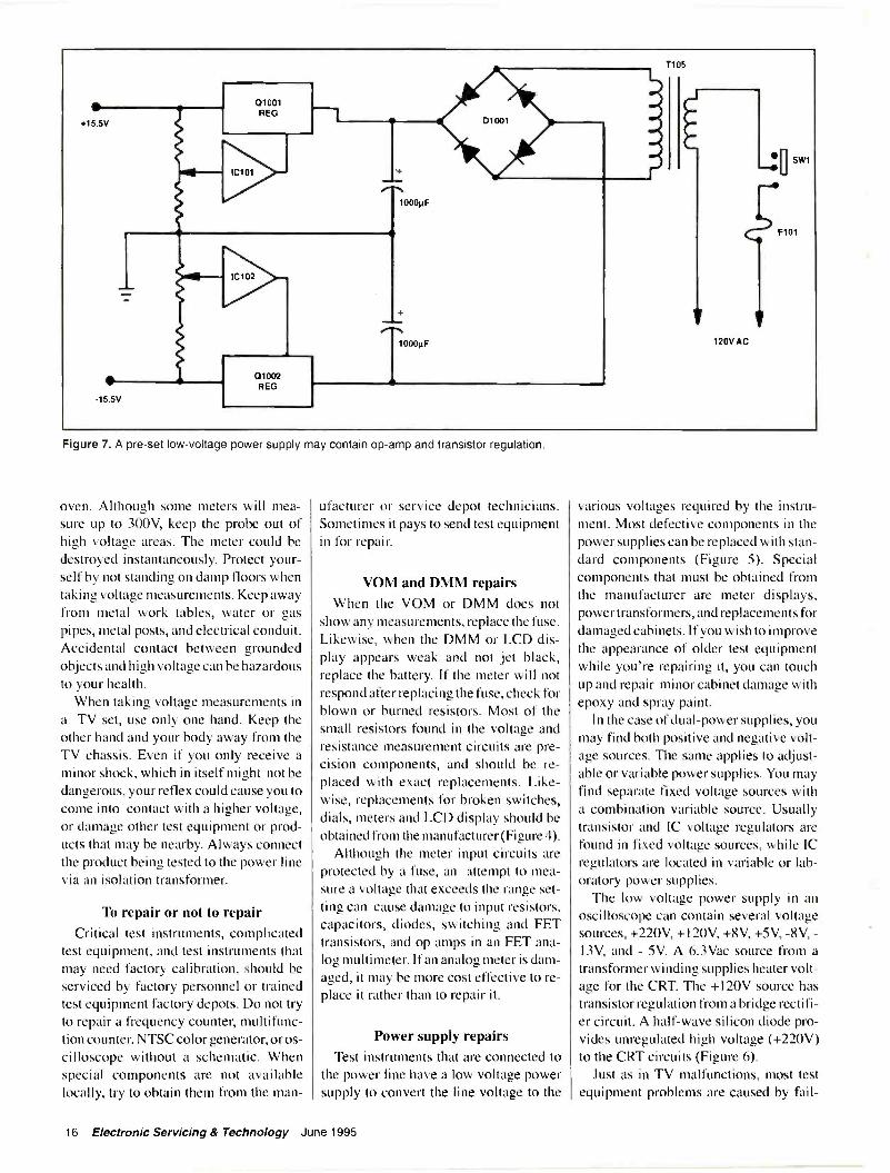
Figure 7. A pre-set low -voltage power supply may contain op -amp and transistor regulation.
oven. Although some meters will mea-sure up to 300V, keep the probe out ofhigh voltage areas. The meter could bedestroyed instantaneously. Protect your-self by not standing on damp floors whentaking voltage measurements. Keep awayfrom metal work tables, water or gaspipes, metal posts, and electrical conduit.Accidental contact between groundedobjects and high voltage can be hazardousto your health.
When taking voltage measurements ina TV set, use only one hand. Keep theother hand and your body away from theTV chassis. Even if you only receive aminor shock, which in itself might not bedangerous, your reflex could cause you tocome into contact with a higher voltage,or damage other test equipment or prod-ucts that may be nearby. Always connectthe product being tested to the power linevia an isolation transformer.
To repair or not to repairCritical test instruments, complicated
test equipment, and test instruments thatmay need factory calibration, should beserviced by factory personnel or trainedtest equipment factory depots. Do not tryto repair a frequency counter, multifunc-tion counter, NTSC color generator, or os-cilloscope without a schematic. Whenspecial components are not availablelocally, try to obtain them from the man-
ufacturer or service depot technicians.Sometimes it pays to send test equipmentin for repair.
VOM and DMM repairsWhen the VOM or DMM does not
show any measurements, replace the fuse.Likewise, when the DMM or LCD dis-play appears weak and not jet black,replace the battery. If the meter will notrespond after replacing the fuse, check forblown or burned resistors. Most of thesmall resistors found in the voltage andresistance measurement circuits are pre-cision components, and should be re-placed with exact replacements. Like-wise, replacements for broken switches,dials, meters and LCD display should beobtained from the manufacturer (Figure 4).
Although the meter input circuits areprotected by a fuse, an attempt to mea-sure a voltage that exceeds the range set-ting can cause damage to input resistors,capacitors, diodes, switching and FETtransistors, and op amps in an FET ana-log multimeter. If an analog meter is dam-aged, it may be more cost effective to re-place it rather than to repair it.
Power supply repairsTest instruments that are connected to
the power line have a low voltage powersupply to convert the line voltage to the
various voltages required by the instru-ment. Most defective components in thepower supplies can be replaced with stan-dard components (Figure 5). Specialcomponents that must be obtained fromthe manufacturer are meter displays,power transformers, and replacements fordamaged cabinets. If you wish to improvethe appearance of older test equipmentwhile you're repairing it, you can touchup and repair minor cabinet damage withepoxy and spray paint.
In the case of dual -power supplies, youmay find both positive and negative volt-age sources. The same applies to adjust-able or variable power supplies. You mayfind separate fixed voltage sources witha combination variable source. Usuallytransistor and IC voltage regulators arefound in fixed voltage sources, while ICregulators are located in variable or lab-oratory power supplies.
The low voltage power supply in anoscilloscope can contain several voltagesources, +220V, +120V, +8V, +5V, -8V, -13V, and - 5V. A 6.3Vac source from atransformer winding supplies heater volt-age for the CRT. The +120V source hastransistor regulation from a bridge rectifi-er circuit. A half -wave silicon diode pro-vides unregulated high voltage (+220V)to the CRT circuits (Figure 6).
Just as in TV malfunctions, most testequipment problems are caused by fail -
16 Electronic Servicing & Technology June 1995
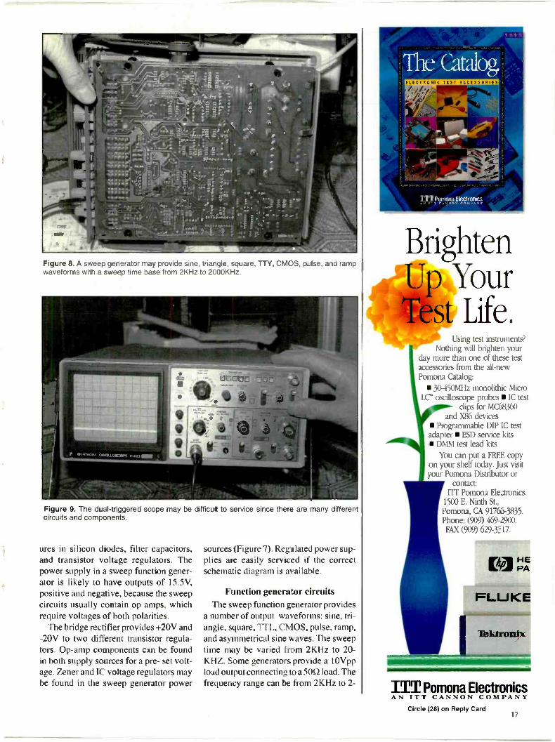
Figure 8. A sweep generator may provide sine, triangle, square, TTY, CMOS, pulse, and rampwaveforms with a sweep time base from 2KHz to 2000KHz.
Figure 9. The dual-tr,ggered scope may be difficut to service since there are many differentcircuits and components.
ures in silicon diodes, filter capacitors,and transistor voltage regulators. Thepower supply in a sweep function gener-ator is likely to have outputs of 15.5V,positive and negative, because the sweepcircuits usually contain op amps, whichrequire voltages of both polarities.
The bridge rectifier provides +20V and-20V to two different transistor regula-tors. Op -amp components can be foundin both supply sources for a pre- set volt-age. Zener and IC voltage regulators maybe found in the sweep generator power
sources (Figure 7). Regulated power sup-plies are easily serviced if the correctschematic diagram is available.
Function generator circuitsThe sweep function generator provides
a number of output waveforms: sine, tri-angle, square, TTL, CMOS, pulse, ramp,and asymmetrical sine waves. The sweeptime may be varied from 2KHz to 20-KHZ. Some generators provide a 10Vppload output connecting to a 500 load. Thefrequency range can be from 2KHz to 2-
NW
BrightenUp YourTest Life.
Using test instruments?Nothing will brighten your
day more than one of these testaccessories from the all -newPomona Catalog:
30-450MHz monolithic MicroLC' oscilloscope probes IC test
clips for MC68360and X86 devices
Programmable DIP IC testadapter ESD service kits DMM test lead kits
You can put a FREE copyon your shelf today. Just visitniir Pomona Distributor or
contact:ITT Pomona Eleztronics.
1500 E. Ninth St.,Pomona, CA 91766-3835.Phone: (909) 469-2900.FAX (909) 629-1=17.
E-01PA
FLUKE
Tektronix
ITT Pomona ElectronicsCircle (28) on Reply Card
17

Figure 10. The CRT in the scope has deflection plates instead of a vertical and horizontal yoke assembly.
ES&T Calendar
June 4-5, 1995Regional TrainingCEDIA(CustomElectronicDesign &
Installation Assn.)Idianapolis, IN1-800-CEDIA30
June 17-19, 1995CES Specialty Audio & Home
Theater Trade ShowEIA/CEGChicago, IL703-907-7600
July 31-August 5, 1995National Professional Electronics
ConferenceArlington, VANational Electronics Service Dealers
Association817-921-9062
October 10-12, 1995CES MexicoMexico City, Mexico703-329-1380
October 26-27, 1995Systems Support ExpoMoscone CenterSan Francisco, CA10:00 am to 5:00 pm dailyFax: 207-846-0657
MHz in seven different ranges (Figure 8).Besides the power supply, the sweep
circuits consist of many diodes, bridgesignal diodes, transistors, and op -amp ICcomponents. You may find quad op -ampsin many of the circuits. Defective transis-tors, diodes and op -amps cause most ofthe service problems. If you run into apiece of test equipment whose push -typefunction selection switches operate errat-ically, spray cleaning fluid into them. Ifyou find that the output waveforms areunstable, it could be the result of bentshields or metal grounding pins, orcracked PC boards, especially if the gen-erator has been accidentally knocked offthe bench, or otherwise mistreated.
Signal, audio and function generatorscan easily be damaged when high voltagecomes in contact with the RF or audio ca-bles and probes. Besides blowing the linefuse, damage to the front end or signaloutput can result in coupling capacitorarcover, or damage to the transistor, FETtransistors, or IC's. Erratic operation maybe caused by a broken or dirty trimmerpot. Suspect poor filtering in the genera-tor when hum bars are found injected intothe product under test.
The oscilloscopeYou may find that the scope is a diffi-
cult instrument to service. Do not attemptto repair an oscilloscope without a sche-matic. Today's dual -triggered scope mayhave such features as channel 1 (X) inputto attenuator, input amp, 2nd attenuator,
CH I preamp that feeds into a diode gate.Channel 2 (Y) signal input has attenua-tor, input amp, 2nd attenuator, CH2 pre -amp, and feeds into the same diode gate.The diode gate signal feeds into a verti-cal amp, delay line, vertical output amp,and to the vertical deflection plates of theCRT (Figure 9). The internal trigger inputgoes to the trigger generator, sweep delay,sweep generator, horizontal display, hor-izontal amp, and on to the horizontal de-flection plates for the CRT.
Besides these signal stages, Z axis amp,square wave calibration, focus and inten-sity control, CHI positive offset and off-set networks are part of the scope circuits.Auto focus and high voltage circuits pro-vide high voltage to the anode button andthe focus grid of the cathode ray tube (Fig-ure 10). Notice that the scope CRT useselectrostatic deflection plates rather thenthe vertical and horizontal yoke assemblyused in TV sets.
ConclusionSimple repairs to test equipment, such as
replacing fuses and batteries, and repairingpower supplies, should pose no majorproblems for a consumer electronics ser-vicing technician. Test instruments withcritical circuits and parts should be sent tothe factory for repair. Always secure aschematic when attempting to service dif-ficult and complicated circuits. A goodclean up, removal of dust and fingerprints,and cigarette burns, may make the testinstrument appear new once again.
18 Electronic Servicing & Technology June 1995
Setting up a servicing benchBy the ES&T Staff
The service bench is the heart of the ser-vice center. It's important, of course, tohave a neat, attractive reception area, effi-cient offices for the management, and anadequate facility in general. But everypenny that's brought into the business isgenerated by the technicians who servicethe customers' equipment. It's of the ut-most importance that those technicianshave a comfortable, efficient, well-equipped, well lighted place to work.
The elements of a test benchAt a quick glance, it's not always pos-
sible to appreciate what's needed in anefficient service bench. There's usually alot more there than meets the eye. Aninventory of the elements of a test benchcan be revealing. Following is a list of thethings that make up a test bench. No doubtmost technicians and service managerscould add to this list.
Surface area for the product, testequipment, tools, etc.
Storage: drawers, shelves, bins, etc. Tools Soldering/desoldering equipment Test equipment Supplies Lighting: general, task and spot Power: ac, isolated ac, variable ac/dc
power supply ESD (electrostatic discharge)
protection Holder for service literature Communications Forms/writing implements Chemicals Computer terminal Replacement parts/supplies reception
Everything necessary at handIn general, the service bench should
have everything necessary to get the jobdone, and nothing that is not necessary toget the job done. In other words, if thetechnician needs an oscilloscope everyday, or almost every day, the oscilloscopeshould be there and available. But if heneeds, say, a function generator once amonth, it should be available nearby, butshouldn't be cluttering up the work area.
Many of the elements mentioned above
are self explanatory, but let's go into a lit-tle more detail about some of the criticalelements.
LightingThis is an area that is frequently ne-
glected. In many service centers the ser-vice area has dark walls, ceilings, andfloors. In some cases, even the work-bench, shelves and back panels are dark.The lighting is provided by a few fluo-rescent fixtures and an adjustable lamp onthe bench.
By any standards, consumer electronicsservicing constitutes a difficult seeingtask. The components in the product andprinted circuit board traces in modernproducts are so tiny as to be almost invis-ible. The service literature in many caseshas close packed wiring patterns, tinycomponent symbols and small print thatmakes itdifficult for the technician to read.
Today's service centers should beequipped with comfortable, non -glaregeneral lighting to provide adequate illu-mination. The bench should have not onlyat least one good task lamp for close- upillumination, but also some sort of spotlight, similar to a flashlight, for seeinginto thaw dark tight places.
PowerMany consumer electronics products
these days use a bridge rectifier in thepower supply. This means that at least aportion of the circuitry is "hot," and if aline -powered test instrument is used totest the line -powered product, a short cir-cuit will occur, and damage will be done.
It could save a great deal of grief to sim-ply make sure that every bench is suppliedwith ac from an isolation transformer, andto make it a standard practice to plugproducts being serviced into the isolatedsupply.
ESD (electrostatic discharge)protection
Almost every consumer electronicsproduct made today contains large-scaleintegrated circuits that are susceptible toelectrostatic discharge damage. If thesedevices are handled without the necessaryprecautions they may be destroyed ordamaged.
Every service position should provideas much protection from this type of dam-age as possible: grounding wrist straps,static dissipative work surfaces, and sta-tic protective bags for storage, whereverpossible.
CommunicationsIn a small service center, the idea of
communication for the service bench mayseem obvious; the technician merely has
June 1995 Electronic Servicing & Technology 19
To 0 rider43favkalssuesSend $3.50 Per Issue
When ordering back issues include the following informatio 1.Name, address, city, state & zip. Please make a list of the issuesyou're requesting. When paying by credit card send the numberalong with the expiration date. Check, Money Order, Mastercard.VISA, Discover and AMEX accepted.
Complete your collection today.1 -800-853-9797
or Fax 1 -5 1 6-68 1-2926Electronic Servicing & Technology
76 North Broadway, Hicksville, NY 11801
T PRI EYTEST QUI MENT
-10111111111110101GoldStar offers a comprehensive line of
affordable Analog and Digital Storage Oscilloscopesfor your diagnostic needs.
Signal Delay Lines Variable Holdoff TV Sync Max. Sweep Time of 2ns/div.
Digital Storage with CRTReadout and Cursor Control
OS -3020: 20 MHz, 20 MS/s
OS -3040: 40 MHz, 20 MS/s
OS -3060: 60 MHz, 20 MS/s
Analog CRT Readoutand Cursor Control
OS-902RB: 20 MHz,Delayed Sweep
OS-904RD: 40 MHz,Delayed Sweep
Analog
OS -9020A: 20MHz, Basic
OS -9040D: 40MHz, Delayed Sweep
OS -9060D: 60MHz, Delayed Sweep
OS -8100A: 100MHz, Delayed Sweep
OS -9020G: 20MHz with 1MHzFunction Generator
Don? forget the other sensibly priced instruments available from GoldStar(Sweep Function Generators, Frequency and Universal -Counters,
Bench Power Supplies, and Bench and Handheld -Digital Multimeters).
LG PrecisionThe Sensible Source
13013 East 166th St., Cerritos, CA 90701 310.404.0101 fax: 310.921.6227
to call out to someone nearby. But in larg-er service centers, the technician at thebench may be a long way from the officeor the replacement parts/supply area. If atechnician needs to check on the avail-ability of service literature, certain parts,or other requirements, it could mean sev-eral trips a day, causing productivity tosuffer.
Such trips could be minimized by pro-viding intercom communications at everybench. The cost of such a system mightbe quickly recouped through increases inproductivity. Another method of provid-ing this communication would be by plac-ing a computer terminal at every positionthat would allow the technician to placerequests via the keyboard.
Parts/materialsHand in hand with good communica-
tions goes good parts handling. In theaverage medium to large service center,when a technician has isolated a problemto the component level, he walks to theparts/supplies area and submits a requestfor what he needs. The supply person maybe busy at the time, thus causing delays.A system such as this can cause a greatdeal of wasted time.
In one service center operated by a ma-jor manufacturer, every service positionhas not only a means of communication,but a pneumatic tube station. Under thissystem, once the technician has isolatedthe problem, he can order the parts or sup-plies he requires via the communicationssystem and have them delivered to himwithout ever moving from the bench.
Of course, a system such as this re-quires a considerable up -front invest-ment, but the increased efficiency canmore than offset the cost.
Planning is essentialAt one time, not so long ago, it was pos-
sible to put together a test bench withoutmuch planning. The climate of today, inwhich many products are not only inex-pensive and therefore marginally ser-viceable, but they are also complex andcrammed with tiny components connect-ed together by hair -thin traces, and con-sumers are increasingly demanding, re-quires that close attention is paid to everydetail of the service environment.
Careful planning of the test bench sothat everything needed by the technicianis where he needs it when he needs it cancreate the efficiency needed to prosper inthese difficult times.
Circle (30) on Reply Card
20 Electronic Servicing & Technology June 1995

Recycling electronic devicesBy Dale C. Shackelford
Looking for a specific component in a
box of salvaged printed circuit boards isone of the most miserable tasks that anelectronics servicing technician can face.If your service center is anything likemine used to be, salvaged boards andcomponents are tangled in a jungle ofhook-up wire, where sharp edges andpointed solder connections seem to stalkunsuspecting knuckles and fingers.
Once the proper board is found, usual-ly at the bottom of the pile, the compo-nent you had envisioned as the cure foryour repair/ modification project is eithermissing from the board, broken in half, ordiscolored due to excessive heat. For-tunately, there are cures for this situation,whereby a service center can save con-siderable time, money and effort when itcomes to dealing with salvaged parts.
Orderly recyclingRecycling modern electronic devices
requires a little forethought and planning,but the rewards for salvaging these prod-ucts will far outweigh the minor incon-veniences. Many service center ownershave found that hiring a part time work-er, whose primary responsibility is to stripsalvaged appliances, is extremely prof-itable, because it reduces the time spentsearching for used components and re-moving them from circuit boards later.Doing it this way also saves storage space.If recycling used electronic devices is inyour future, here are some tips that willenhance that process.
When parting out a typical televisionreceiver (for example most technicianswill remove the chassis, tuners, yoke,speakers and control modules (bright-ness, color, tint, etc.) as a single unit, leav-ing all of the subsystems attached to themain circuit board by their wires. If thetelevision was operating properly beforeit was dismantled, and there is a possibil-ity that the inner workings of the set willbe installed in a new cabinet, the entireunit can be placed in a cardboard box, andstored in a cool, dry area.
The box in which the unit is storedShackelford is an independent consumer electronicstechnician
Figure 1. When salvaging a tuner trom a scrapped TV set. remove the tuner from the mountingbracket to save storage space.
should be clearly marked as containing acomplete(and operating)unit, and shouldlist the chassis brand and type (i.e.: Mag-navox S4 chassis/l992/Electronic tun-ing). Taping the box closed should pre-vent hurried (but well intentioned) tech-nicians from snatching parts.
These recycled components should al-ways be identified as such, and used in re-pairs only with the full knowledge andconsent of the customer.
Removing and identifyingcomponents
If the inner workings of the salvagedset will be used as components for futurerepairs rather than being used as a whole,you should begin recycling the set by re-moving all wires between the main chas-sis and the subassemblies. For example,cut all wires from the main chassis to thetuner should be cut (or simply disconnectthem if harnesses are used), leaving aboutone inch of the insulation at each connec-tion. This will aid the technician in iden-tifying the proper connection point if thetuner is going to be used in another set.
Clipping wires not equipped with plugs/harnesses will save considerable time indesoldering the wire connections, and re-duce the possibility of heat damage tocomponents. Wires with plugs/harnesseson both ends may be stored for future use.Making sure that all unnecessary wiringhas been removed will virtually eliminate
the "wire jungle'. that is so often found inboxes containing salvaged parts.
Handling tunersWhen removing tuners from television
cabinets, it is a good idea to remove thetuners themselves from the mountingbrackets (Figure 1). This will reduce stor-age space. Analog UHF tuners can usu-ally be discarded, as they are rarely re-placed in modern sets, and the VHF toUHF wiring should be removed. As anaid in future identification, clearly marktuners with the brand/model of the setfrom which they were extracted and markbasic connection points (B+, AGC, IF,etc.). If there is any doubt as to the prop-er connections, the schematic can be usedto make the proper determination. For thisreason. the marking process works wellwith all types of subassemblies.
Expensive componentsIt is almost a given that relatively ex-
pensive components such as flybacktransformers, microcomputers and mi-croprocessor ICs will be removed fromthe salvaged unit if they are in good con-dition. These components should be re-moved from the board in the same man-ner as would the same component foundin a working set, so observe electrostaticdischarge (ESD) precautions and use heatsinks on the conductors between the com-ponent and the board. When storing corn -
June 1995 Electronic Servicing & Technology 23

Factory DirectAerosols!
4
Proven aerosols, wholesale prices.
FREE delivery in continental USA.
Most orders ship same day.
Safer formulations.
No time limit money back guarantee. Distributors welcome.
Call Mon -Fri, 8-5 EST forFREE brochure and trial offers.
1-800-227-5538Circle (41) on Reply Card
i7 N 1N 7 I
Technical Parts and Suppliesfor the Service Industry
41k 0'4Eon,
Quality Parts - LOW Prices
Free Catalog(800) 223-3205
Electronix Corporation313 W Main St Fairborn, OH 45324
Phone (513) 878-1828 Fax (513) 878-1972
Figure 2. One way to speed up the removal of the components is to heat the solder side of theboard with a high wattage soldering gun. or a desoldering torch.
ponents that are susceptible to ESD, usestatic proof bags, cases or foam, and storeICs such as EPROMs where they will notbe exposed to ultraviolet light. All thesecomponents should be clearly marked.
Modular circuitsThe next phase of the recycling process
is to remove all modular circuits on theboard. These circuits, which are oftenself-contained within a shielded housing,are often plugged into the main circuitboard in one fashion or another. When re-moving these modular circuits, markthem clearly as to the module type (pic-ture -in -picture, stereo, etc.) the modelnumber and location (as noted on theschematic), as these modules are indis-pensable for testing/servicing other sets.When removing modular circuits that aresoldered to the main board, be sure to useheat sinks to avoid heat damage.
Marking ComponentsBecause of the relatively high cost of
power transistors (such as horizontal out-puts, voltage regulators and others, gen-erally connected to heat sinks), thesecomponents should be removed andsaved for future repairs. In most cases, thetransistors themselves will contain facto-
ry markings. However, a piece of mask-ing tape on the transistor, indicating theaftermarket cross reference numbers ofthe aftermarket company typically usedin the service center, will save the tech-nician a lot of time later in crossing fac-tory numbers to ECG, SK, NTE or otheraftermarket/replacement numbers. Ob-viously, these transistors should be re-moved from the heat sinks at once, beforebeing stored in order to save storagespace. Heat sinks themselves are rarelyreplaced in modern sets.
Smaller transformers and relaysshould be removed next, paying particu-lar attention to their location on the board.Because these components are rarely fac-tory marked, consult the schematic dia-gram for the particular set, and mark thecomponent(s) with the values (primary &secondary inductance for transformers,voltages for relays, etc.). The amount oftime expended in determining these val-ues will save the technician much workduring a very busy time in the future, asthese components are often used in de-vices other than the type/brand of devicefrom which they were extracted.
Removing the Small ComponentsBy now, the only components left on
Circle (24) on Reply Card24 Electronic Servicing & Technology June 1995

the circuit board will be some commonICs, resistors, capacitors, inductors, anddiodes. Smaller transistors and ICs, onceremoved in the typical manner, can be"crossed", and marked with a small pieceof masking tape with the cross numberwritten on it. The transistors can bechecked in seconds with a typical tran-sistor checker before being separated andstored with like types.
Removing the remaining componentsfrom the circuit board (resistors, caps, di-odes, etc.) can be accomplished in a num-ber of ways, though, because time is ofthe essence in these operations, the ser-vice center owner will have to decidewhich method would be the most effi-cient. Most service centers will use a tra-ditional vacuum assisted desoldering sta-tion to remove solder from componentleads. An alternative to this would be toplace the circuit board in a vise (Figure2), and to heat the solder with a highwattage soldering gun, or to make theprocess faster, a small torch.
Once the solder is heated on the leadsof the components (or a small area withthe torch), the components can be pulled
out of the board with pliers. In either case,be sure to pull only on the leads, never onthe components themselves, and applyonly the amount of heat necessary to meltthe solder. Clamping the pliers tightly onthe component leads will also act as a heatsink, reducing destructive heat build-upin the component.
Eliminating the solderNow that all components have been re-
moved from the circuit board (whetherthey will be used or not), it is a good ideato remove any remaining solder from theboard. This practice is recommended, asthe lead in the solder may be consideredhazardous waste in your area. Check witha company that manufactures solder todetermine the best and safest way to do so.
Recycling makes senseWhile the recycling of electronic prod-
ucts may seem at first to consume a greatdeal of time and effort, it really isn't, espe-cially when done on a volume basis. Theservice centers that has more used partsthan it knows what to do with, may find
that it makes sense to donate some of themto local (electronics) technical schools ,while some service center have madeprofits by packaging and selling usedparts to other shops throughout the coun-try. Used components also help the envi-ronment, as there is less waste, lessground water and soil contamination andless energy used in the production of thesecomponents. The metal found in thesesets (wire, shields, heat sinks, etc.) can allbe easily recycled, as can the wood/plas-tic cabinets.
In addition to enjoying the benefits de-scribed in the recycling of appliances, youmay well be leading a young part-timeworker down a career path that you and Ihave found both lucrative and challeng-ing, and providing the basis for a careerthat will last a lifetime. Separating com-ponents, making measurements, "cross-ing" manufacturer numbers with after -market identifications and other such(dreary) tasks will certainly teach thebasics of electronics, bring the satisfac-tion of a job well done, and if properlyorchestrated, increase the (environmentaland overall) efficiency of your shop.
NORTH AMERICA'S LARGEST AUTHORIZEDOffice Equipment & Circuit Board Repair Center
COMPLETEMACHINE REPAIR
Facsimiles Laser Printers
Personal Copiers Typewriters
*FAST TURNAROUND>GENUINE OEM PARTS*FACTORY AUTHORIZED>BEST PRICING AND QUALITY>COMPONENT LEVEL REPAIR
THERMAL FAX REPAIR ONLY S35.00 (Pits Parts)
QUALITYSERVICE PRODUCTS
INCLUDES THESE TOOL&r PMpa Serevolnver Sok:Wang Iron6' Philp. Screw:Inver Solder Wok
Pfilepa Senneelnver Solder PackII' Slotted &reweave, Melee Scale8 I /2' Meg Sereadaver Fee
mm Nue:Inver Spang Hoek8 awn Nuldneer Metro Feeler GaugeSmall Vkite.Gnes Electectene Keefe
Longnose Plan Oval Saab Basel%4' Ougonal Cutlers Decimal TapeExternal Fling Nora 2 in Oder4 rat 8a1 Peen Hammer Pen Loyelaelnc Alen Key Set Cable 10.3,32' R. Punch
THE HYTEC STANDARD TOOL KIT
Choice of two use styles -6' deep Polyethylene hard case with 2 pallets
or5 1/2' deep ktrge zippered case
MENTION THIS AD FOR A 5% DISCOUNT
F394444 1,1 EL" DEVICES, Inc.broth& 43 EtNaUNO
ParlaSaliC4548 ParkBreeze Ct. Orlando, FL 32808800-883-1001 Fax: 407-297-4310
CALL FOR OUR LATEST CATALOGAND REPAIR LISTINGS -
1-800-883-1001Circle (27) on Reply Card
June 1995 Electronic Servicing & Technology 25

More ways to diversify yourbusinessB1 BIM J01111S011
When it comes right down to it, there areonly so many kinds of electronic circuits,they're just applied in different ways.That's especially true of most new elec-tronic equipment where the heart of thesystem is a microprocessor. For example.the only real difference between a person-al computer system and a data acquisitionsystem is the kind of I/O that is employedand the software that runs it.
The topic of this article is simply a spe-cific application of a data acquisition sys-tem. If you're currently in the consumerelectronics service field and looking toexpand your horizons, you might find thisinteresting. All you have to do is transfersome of the your current expertise into anew area.
The subject at hand is broadly labeledautomotive test equipment. These prod-ucts have a lot in common with both com-puters and consumer electronics. CRTdisplays, signal amplifiers, digital cir-cuits, microprocessors, monitors, analogand digital I/O, and printers are just a fewof the subsystems that you're probablyalready familiar with.
Service of automotive test equipmentinvolves routine maintenance and cali-bration procedures as well as fault trou-bleshooting, both in the service center andon site. In addition to being interestingfrom a technical perspective, automotivetest equipment can be a lucrative productto service, if you know how. Let's take abroad look at what's involved in automo-tive test equipment service. First, whatkinds of equipment are we talking about?
The productsAutomotive service centers use two
main kinds of electronic test equipment:engine analyzers, and wheel alignmentand balancing equipment. Smaller, hand-held test equipment like timing lights,battery load testers, etc. make up a limit-ed, but still profitable side market.
Johnson is a journeyman electronics servicing technicianand an instructor of technology at the Northern AlbertaInstitute of Technology in Edmonton, Alberta, Canada.
Figure la. A sequential display on the read-out of an automotive scope shows the firingpatterns of each of the spark plugs in theengine allowing comparison of peak values.This is the pattern of a six -cylinder engine.
If you're involved in technology forthe same reasons as I am, you'll probablyfind the technical aspects of automotivetest equipment interesting. But we allknow that the bottom line is the decidingfactor, so we'd better look at the businessend of things first.
Business considerations
There aren't a lot of service companiesdoing this kind of work in any given geo-graphical area, mainly because of the lim-ited number of manufacturers of testequipment.
As you probably know, performingthird party service without the support ofthe manufacturer is kind of like slow star-vation. To make it in this business youhave to be a manufacturer's authorizedservice center. After you have that autho-rization, you can do third party service onthe competition's equipment (trade-ins,etc.) the same way as you do now. Thebest way to get in is to keep your eyesopen. Find out who, if anyone, is doingservice now and keep a eye on them.When changes come, and they inevitablydo, be ready to take advantage of theopportunity.
Take a look in your Yellow Pages underAutomotive Test Equipment. You'll find
Figure lb. This automotive scope display,sometimes called a "raster" pattern, displaysthe cylinder firing patterns on consecutivesweeps, allowing the technician to comparetheir time related characteristics.
Figure lc. This scope display superimposesall of the firing patterns over one another, allow-ing the technician to check for overall unifor-mity in the patterns.
three main manufacturers of automotiveanalyzers: Allen Test products, Bear, andSun. Snap-On has been making progresswith its equipment in the last few years aswell. More may have sprung up in the lastcouple of years, but these are the ones whohave been around for a while. Hunter,FMC and Bear (the same company thatsells analyzers) make wheel alignmentand balancing equipment.
In some cases the manufacturers haveset up their own factory service centers,but usually they contract with local ser-
26 Electronic Servicing & Technology June 1995

vice companies to represent them. Youmight also find yourself working closelywith a local sales rep (again, either a com-pany employee or a manufacturer's rep).
Warranty serviceThe profitability of this kind of
arrangement comes in a variety of ways.First, warranty service. As usual, themanufacturer stipulates flat rates for war-ranty service (usually, shamelessly low).This is where specific training on theirequipment becomes necessary. As I men-tioned before, you already have some ex-pertise, but there is a difference betweenservicing and servicing profitably. Timeis the key, and with factory training youcan speed up the process. The manufac-turer should provide you with this train-ing, and pay for it.
If you're not an automotive whiz, don'tcount yourself out. You don't have to be.With some factory training, after a shortperiod of time you'll be up to speed withas much of the mechanical end of thingsas you need. You'll also pick up lots ofinformation from working with the auto-motive technicians.
What you charge for out of warrantyservice, of course, is up to you, and whatthe market will bear. You know what kindof hourly rate you need to charge in orderto break even. Factor in the learningcurve, the significant outlay you will haveto put into specialized parts, travel and theoverhead of extra space in the service cen-ter, just to name a few items to think aboutwhen servicing these products.
The good news is that this is a spe-cialized service and the customer proba-bly won't get it from anyone else in theclose vicinity. I'm not suggesting that yougouge them, but the customer should paywhat your time and expert knowledge isworth. Remember, your customer is in theservice business too. He has invested thir-ty to forty thousand dollars in this equip-ment and expects to make money with it.You should too.
Replacement partsReplacement parts for automotive test
equipment are obscenely expensive. Anoxygen sensor for an exhaust gas analyz-er runs the customer between two andthree hundred dollars. Some service cen-ters replace several of these a year. A leadset (the cables used to connect an analyz-er to the vehicle) can list at five hundred
TO ,GNITior
TO PLUG #1
GREEN
ENGINE HARNESS HOOKUP
TO ALTERNATN
TO STARTER
(GM)
BLACK TO GROUND
Figure 2. A number of leads are required to connect the engine analyzer to the various points itwill be monitoring. These leads are subject to a great deal of abuse, and may require frequentrepair or replacement.
dollars and up. A specification ROM foran aligner is in the neighborhood of eightydollars. Parts are a definite money makerbut you have to keep a reasonable quan-tity in stock. A set of replacement mod-ules by themselves might run you tenthousand dollars.
But take heart, there are positive as-pects to this. Sometimes the factory willconsign you modules for warranty use.You can build your own lead sets for ahundred dollars, or you can rebuild thecustomer's for half that price. And, ser-vice centers have been known to repro-gram specification ROM's with the latestdata. (Don't shoot me. The factory reptold me it was legal.)
Third party serviceThe other area of potential profit is the
third party work that comes along withthis. Timing lights, battery chargers, bat-tery load testers, and a variety of otherequipment just starts showing up at yourdoor. The local jobbers who supply partsand tools to the automotive shops willoften set up a service arrangement withyou. Most of it is relatively easy to fix,though you might have to locate a wholenew set of parts suppliers. This is the kindof work to keep your junior technicianbusy with on slow days (when he isn'tbuilding lead sets).
There can be a few other unexpected
off -shoots in this kind of business. For ex-ample, installations and training. Wheelalignment equipment is operated with thevehicle on a special kind of hoist. It maynot be the kind of work you expected todo, but the money earned installing a hoistin a automotive shop can be spent just aseasily as any other cash earned. After thehoist is in, and the aligner set up, you cantrain the automotive technician on how tooperate it, (demonstrate on your own ve-hicle and get a free wheel alignment).
Since you're already in the customer'sshop you might as well sell him a set ofalignment shims (five hundred dollars fora starter set) and the tools to install themwhile you're there. Next year you'll beback to update his specifications and cal-ibrate the whole system for somewherearound two hundred dollars. You mightbe surprised to find that the customer willbe very satisfied with all of this. He makesgood money himself off this equipment.
There are lots of other interesting lit-tle idiosyncrasies to this kind of businessthat I haven't mentioned, but this givesyou a fairly good picture of what to lookfor. Now let's do an overview of the tech-nical side.
Engine analyzersModem engine analyzers are comput-
ers that are designed to gather data fromthe vehicle, process it, and print out an
June 1955 Electronic Servicing & Technology 27

Figure 3. The inductive pickup that generatesthe signal from number one spark plug con-sists of a U-shaped ferrite core with a few turnsof solid wire wound around it, and another core,the "I -core," which completes the magnetic cir-cuit when clamped to the U-shaped core overthe spark plug wire.
analysis of the engine's condition. Mostanalyzers perform diagnostics and rec-ommend service procedures such as thereplacement of spark plugs, the battery,or other parts. Older versions, called auto-motive scopes, do most of the same mea-surements, but it is up to the automotivetechnician to interpret the results. Let'stake a look at what, and how these ma-chines measure in order to see what isinvolved in servicing them.
The central idea of an automotivescope (the older, manual types) is to dis-play, on a CRT, the electrical firing pat-terns for each cylinder of the engine, fromeither the primary or the secondary sideof the ignition coil. Figure 1 shows thethree kinds of displays.
The first is a sequential display wherethe firing patterns occur one after anoth-er, allowing comparison of their peak val-ues (this one is a six cylinder). The sec-ond pattern shown is sometimes called araster pattern. The six cylinder patternsare displayed on consecutive sweeps.This display allows comparison of theirtime related characteristics. The third dis-play type superimposes all six patternsover one another. This allows the techni-cian to check for overall uniformity in thepatterns. Some scopes also provide ahigher speed sweep to expand the displayfor higher resolution.
Obviously these displays are createdelectronically by controlling the horizon-tal and vertical deflection waveforms, andsynchronizing them with the input sig-nals. The techniques are somewhat simi-lar to the operation of an oscilloscope,(which is a vector display as opposed tothe raster display of a television).
The scope performs a number of otherfunctions but, before considering them,we need to know what kinds of inputs arepicked up from the vehicle. Most of the
repair problems are related to inputs, sothis is a good place to start. These inputsare connected to the scope, from the vehi-cle, through a set of leads, some of them16 gauge neoprene pairs (like extensioncord wire), and some neoprene covered,shielded single -conductor and dual -con-ductor cables (Figure 2).
They are often connected to the scopethrough one or more plastic AMP connec-tors (which break and have to be replacedquite often). The leads break, too, or aresometimes chewed up by the fan belts inthe vehicle. If there are more than a fewbad spots in a lead set, a trade-in for a re-built cable is the customer's best bet. Butlet's look at what they actually do.
The leadsLet's first look at the positive and neg-
ative leads of the battery. The negative(chassis) lead is the ground for the sys-tem, the positive lead allows the scope tomonitor the battery voltage. A currentprobe works in conjunction with the bat-tery clips and clamps over the vehicle'spositive battery cable. It uses a Hall -effecttransducer to indicate the charging or dis-charging current of the battery.
The voltage and current measurementswork together when testing the startingand charging systems. By pushing a but-ton on the scope, the primary side of theignition coil is shorted out so the enginewon't start. The technician then turns onthe ignition, and cranks the engine. Acomparison of the level of cranking cur-rent and the battery voltage drop overtime indicates the condition of the starterand battery.
Next, the technician removes the shortfrom the coil primary, and the engine iscranked again and allowed to start. Again.by monitoring the charging current andbattery voltage the condition of the alter-nator and voltage regulator can be deter-mined. The computerized systems do thisall automatically, just prompting the tech-nician when to crank the engine.
The analyzer can perform another use-ful test while cranking the engine by mon-itoring the instantaneous cranking currentduring the compression cycle of each cyl-inder. A cylinder with poor compressionwill not cause as heavy a current drawfrom the battery. As we'll see further on,the computer "knows" which cylinder iswhich and can display the pertinent infor-mation later.
As mentioned before, one lead (ashielded, single conductor) connects viaan alligator clip, to the primary side of theignition coil. This is the lead which wasshorted to ground inside the scope duringthe starting/charging systems test. It alsoprovides the primary signal for display onthe CRT. Another shielded cable connectsto the secondary side of the coil, but, sincethe secondary is a high voltage, the con-nection is a capacitive clip that connectsaround the high voltage lead from the coilto the distributor cap. Since the secondarysignal is a complex ac waveform it can becapacitively coupled to the scope.
In order to synchronize the signals andtrigger the scope trace, another input con-nects to the number one spark plug. In thiscase an inductive pickup is used. Figure3 shows what's inside the pickup. A fewturns of solid wire are wound around a U-shaped ferrite core. Another core, (straightthis time, and called an I -core), completesthe magnetic circuit when clamped overthe number one spark plug wire. Thespark plug wire becomes the primarywinding of the transformer which sendstrigger pulses back to the scope.
A cracked I -core causes a lot of cus-tomer complaints about scopes and ana-lyzers, because an intermittent sync pulsemesses up many of the tests done by thesystem. All it takes to crack an I -core isto drop the number one pickup on the shopfloor once. I usually gave an extra I -coreto good customers and showed them howto detect and replace a bad one. I lost afew service calls but gained good willwith this gesture.
I mentioned earlier that the primaryside of the coil could be shorted out toground, which would inhibit the vehiclefrom starting while testing the battery.With a little digital logic (or the help ofthe computer in an analyzer) individualcylinder firing pulses can be shorted outon every revolution. A comparison of theRPM of the engine with and without thehelp of any given cylinder, provides anindication of the condition of that partic-ular cylinder. On the older scopes, eachcylinder could be tested by pushing con-secutive buttons on the scope. Analyzersperform the test automatically.
Other parametersVacuum is another parameter that
needs to be checked during a typical en-gine analysis. The older scopes had built -
28 Electronic Servicing & Technology June 1995

in vacuum gauge that the technician con-nected via a rubber tube and then inter-preted himself. Newer engine analyzersuse the vacuum signal in their diagnosticengine analysis so the vacuum signal hasto be converted to an electrical signal. Asmall pressure transducer inside the ana-lyzer is used to convert the signal.
Some analyzers also use a temperaturesensor. The ones I have seen were a longprobe that could be used to replace the oildipstick in the vehicle. Again, the analyzerused the engine temperature in its analysis.
The final input to the analyzer isn't real-ly a lead at all; it's the exhaust gas sam-ple probe. The exhaust gas analyzer is asystem unto itself (which shares informa-tion with the analyzer computer). Auto-motive exhaust gas analyzers usuallymeasure the concentration of four gases:carbon monoxide, carbon dioxide, hydro-carbons and oxygen.
The first three gases are detected andmeasured by a sophisticated infrared ab-sorption spectrometer. Oxygen is detect-ed by a polarographic oxygen sensor. Thegas analyzer is used to determine the effi-ciency of the emissions control system of
the engine. The analyzer takes this dataand, with the other information obtained,makes diagnostic decisions about therequired service.
If the primary cause of service toscopes and analyzers is damaged leadsets, gas analyzer problems are a closesecond. Automobile exhaust is prettydirty stuff and the sample system for theanalyzer requires some maintenance.Dirty filters, worn out vacuum pumps,and damaged exhaust probes are justsome of the things to consider. And when-ever service is performed, a quick checkof the calibration is necessary using pre-mixed test gas. Training the automotivetechnician on how to keep the machinerunning is another requirement.
Information outputWhile we're still on the subject of in-
put/output, analyzers use a variety ofmethods to communicate with the tech-nician. Some have light pens which thetechnician uses to select targets on thedata display. Others have QWERTY stylekeyboards. Some use pendant switches toallow the technician to key the analyzer
to specific events from under the hood.Some analyzers have both computer
monitors and analog CRT's for display-ing ignition waveforms. Large analogmeters were common, especially on thescopes and older analyzers, so the auto-motive technician could see the readingsfrom under the hood. Printers supply ahard copy of the data and diagnosticswhich can be presented to the customeras proof of the analysis.
Automotive analyzers can also com-municate with the on -board computers inmany vehicles, and display the informa-tion on screen. Parameters such as faultcodes, coolant temperature, manifold ab-solute pressure and oxygen sensor output,can be displayed at the same time givingthe technician lots of input that he can usefor diagnostic purposes.
There's a lot more that could be saidabout this kind of equipment, and wehaven't even touched on some of the otherautomotive test equipment that's needsservice out there: wheel alignment, bal-ancing and handheld test equipment. Itmight be worth your while to at lea,t ex-plore these areas for yourself.
The ECG SemiconductorMaster Guide.The Last Word
In Replacements.
In the 16th edition ECG SemiconductorMaster Replacement Guide: 4,100 devices,14,000 more crosses for over 276,000 total.Plus, nearly 200 new linear ICs, transistors,diodes, rectifiers, gas -filled surge suppressorsfor Industrial and Entertainment application,At 900 Philips ECGdistributor locations, SnliaTtor call I-SOO-526-935i Choice ,u
ECG PHILIPS
13 New Advanced Chemicals,All CFC/HCFC Free,All From Philips ECG.
Advanced Chemicals for the Electronic andElectrical industries. The ECG line features appli-cation tailored flux removers, electronics washes,degreasers, contact cleaners, head cleaners, circuitrefrigerants, dusters, lubricants and mom. 13 arenew and CFC/HCFC free. Ask for new full -linecatalog at 900 Philips ECGdistributor locations, SmartVor call 1-800-526-9354. Choice s
Philips ECG PHILIPS
Circle (35) on Reply Card Cir:le (34) on Reply Card

Eltia4.04.z.c Ce4P+4,4.44t
;- r_-_) r
DALBANI CORPORATION4225 N.W. 72 ND. AVE. MIAMI. FLORIDA, 33166
TEL: (305) 716-1016 FAX: (305) 594-6588
Circle (23) on Reply Card
TECHNICAL SUPPORT PROGRAMMAKING GOOD MONEY OR JUST GETTING BY ?
Full time Tech -Tip support program,PAPER or COMPUTER in which you maystore your own Tips. Repairs beginning1987 through TODAY. Starting with12,000 Tech -Tips - 163 brands 2,000new tips and cross references addedeach 8 month update plus, a newslet-ter with step by step up to the minute re-pairs. We are constantly improving thisprogram. Our Tech -Tips are actual in-voiced repairs that came directly fromour service center and not copies of vari-ous manufactureres tech tips that arereadily available on the market today.
PAPER OR COMPUTER
TV -MAN TECH -TIPS
"PAY"
We are not a one-shot deal with occa-sional updates at varing prices from a lim-ited number of brands. We are the onlycompany that provides a 30 -day moneyback guarantee on our computer pro-gram and it's legal, licensed and easy tooperate DOS or Windows. Member Bet-ter Business Bureau of Palm BeachCounty and NESDA. Our Demo is"FREE" and so is the phone call.
800 474-3588 M -S, 9am-9pm EST.
MIC,VIsa,Amex,Disc.,COD,Co. Chk, PTO's
Test Your ElectronicsKnowledgeA sampler
By Sam Wilson, WA8RMS
1. In an ac circuit the product of rms voltage multiplied by rms current givesA. rms power.B. true power.C. VARS.D. average power.
2. Two resistors are connected across a constant voltage source. One resistordissipates 3W and the other dissipates 4W. How much power is dissipated by thecircuit?
3. Assume the control grid of a working CRT is held constant. The cathode andcontrol grid are both positive with respect to common. Making the cathode of thetube more positive will make the display
A. brighter.B. less bright.
4. Refer to the CRT described in Question 3. In normal operation the catho(1,..should be
A. more positive than the control grid.B. less positive than the control grid.
5. The phase angle between the voltage and current in an ac circuit is 38°. Whatis the power factor of the circuit?
6. Write the conjugate of 5-j8.
7. The equation for impedance compared to turns ratio is:Np
Ns -
8. In an amplifier, what term is used to describe the ratio of the maximum allow-able input signal to the minimum discernible signal?
9. Which of the following cannot be an octal numberA. 10101010B. 12345678
10. A certain 0.002211F capacitor has a reactance of 3.612. What is the frequency used to determine that reactance?
(Answers to quiz on page 55)
Wilson is the electronics theory consultant for ES&T
Circle (42) on Reply Card
30 Electronic Servicing & Technology June 1995

Computer maintenance anddiagnostics using MS-DOS 6.0By David Presnell
Many computer service calls turn out tobe basic file maintenance calls. Manycustomers will ask you to speed up theirsystems, back-up their hard disks, or tryto recover lost files. You will often findcomputers with the hard disk disorga-nized, not maintained, and highly frag-mented. Such hard disks often containbad clusters and corrupted files that needto be repaired.
You may occasionally come across acomputer that has been infected with avirus. Problems may arise when TSR (ter-minate and stay resident) programs arerunning with the use of certain applica-tions, and hardware conflicts can exist un-noticed for some time before certain pro-grams bring them to life.
Utilities in DOS
Microsoft has included certain utilityand diagnostic programs to aid the user insolving these and other problems in MS-DOS version 6.0 and above. In fact, manyof these problems could have been pre-vented if the user had fully understoodand applied these DOS 6.0 utilities. So, itis left to the computer service technicianto solve these problems.
In many cases, all the technician needsto do is to run a few DOS utilities to solvethe problems, and MS-DOS 6.3 should,by now, be on all late model computers.If it's not, then you should, by all means,sell your customers an upgrade. This arti-cle will look at some of the more usefulutilities and diagnostic programs sup-plied with MS-DOS 6.0 and above.
Getting startedMaintaining a computer, beyond clean-
ing it occasionally, involves keeping per-formance at an optimum level. A comput-er performs very well when it's new, but
Presnell is the owner of an independent computerservicing business and a freelance technical writer.
in time wear and tear, abuse and poormaintenance take their toll. For example,files are added and removed over and overcausing fragmentation of the hard disk.Hard disk drives begin to wear, causingbad clusters and eventually lost data. Newhardware and software is added and notproperly configured.
The physical abuse some people inflicton their computers is even worse. Coffeeor other liquids are spilled, or smoke fromcigarrettes is sucked into the drives. Then,there are the errors in software manage-ment. For example, the new employeeadds some garbage to the AUTOEX-EC.BAT file thinking it had something todo with an executive's parking spot. Anew secretary accidentally deletes last
month's invoices from the hard disk be-cause she didn't get a raise. Then there'sthe disaster just waiting to happen. Thecollege kid who's working part time intro-duces the latest nasty virus on some appli-cation program he lifted from the com-puter lab at school.
Considering all of these existing andpotential problems, it should be obviousthat computers must be maintained. Inthe case of the spilled coffee, get yourselfa computer cleaning kit and go to work.In most cases such accidents don't causepermanent damage if handled correctlyfrom the beginning.
Using the DOS utilitiesFor the rest of the problems mentioned
June 1995 Electronic Servicing & Technology 43

earlier, you will need some utility pro-grams specifically designed to fix theproblem. A number of vendors offer suchutility programs, but in many cases DOS6.0 can do the job just fine.
For accidentally deleted files try UN -DELETE. If your customer is someonewho wondered what the FORMAT com-mand does, and decided to satisfy theircuriosity, you may have to use the UN -FORMAT command. If no files have beensaved to the hard disk since the DELETEor FORMAT command was invoked,DOS 6 can often recover the system to itsoriginal condition.
File maintenance procedures allow youto maximi:e and optimise for perfor-mance. That is, you make the computerperform better at a faster speed. In somecomputer circles you will hear this calledMOP for short, or mopping up the mess.
Before you MOP the system, performa complete hard drive back- up. Duringthe MOP process you might inadvertent-ly delete files, or the entire contents of thehard disk, or just generally make the sit-uation worse than it was when you start-ed, by improperly using the utilities dis-cussed in this article. If you have made acomplete backup, you can always restorethe system to its original condition.
Part of the file maintenance process istalking to the user to determine what filesor directories may be unnecessary so thatyou can erase them from the hard drive.Many hard drives are loaded with filesthat have never been used and never willbe used. Your customer can help you de-termine which to get rid of. Be sure to re-move all related subdirectories from thesystem. This is a good time to try theDELTREE command, which removes adirectory and all its related files and sub -directories at the same time. But don't useDELTREE unless you are absolutely sureof what you're doing.
Checking start-up filesOnce you have backed up the hard drive
and cleaned out the garbage files, you areready to take a look at the start-up files.First, you may wish to take a look at theROM BIOS SET-UP information to besure the BIOS is set up correctly. You canusually enter this set-up upon start-up bypressing the DEL key before the com-puter completes the memory check. Now,at the C prompt, type VER and pressENTER to be sure you're using MS-DOS
Version 6.0 or above. If not, upgradebefore continuing.
After you have checked the ROM BIOSsetup and have rebooted the computer,make a backup copy of the start-up filesby doing the following: At the C prompt,type COPY AUTOEXEC.BAT AUTO-EXEC.OLD and press ENTER. This willmake an exact copy of the AUTOEX-EC.BAT file and name it AUTOEX-EC.OLD. Thus, if something should gowrong, you can always copy the AUTO-EXEC.OLD back to make things the waythey were before. Now type COPY CON-FIG.SYS CONFIG.OLD, and press EN-TER. Again CONFIG.SYS will be copiedto the file named CONFIG.OLD. Itwouldn't hurt to copy these files to a flop-py disk as well.
Editing the AUTOEXEC.BAT fileAt the C prompt, type EDIT AUTOEX-
EC.BAT, and press ENTER. This willstart the DOS EDITOR program and openthe file called AUTOEXEC.BAT. Referto your DOS manual for help in deter-mining what each line of the file means.You need to determine exactly what eachline does, why it's there, and if it needschanging. Be especially curious aboutlines or statements that are not mentionedin the DOS manual's index.
To temporarily disable a line, typeREM at the beginning of the line with thekeyboard set to insert (REM is the pro-grammer's shorthand for "remark,") thecomputer considers any line of code pre-ceded by "REM" to be a remark, and doesnot execute it. To save the changedAUTOEXEC.BAT file; press the ALTkey, the F key, then the X key, and pressENTER, or select YES when asked if youwish to save the file.
You will now have to re -boot the com-puter to see how your changes affect thesystem. You can also type AUTOEXEC,and press ENTER to run the batch files.It's usually best, however, just to re -boot.To re -boot, press and hold down theCTRL key, ALT key, and the DEL key atthe same time to warm boot the system.This method of using REM to disablelines in the AUTOEXEC.BAT file worksgreat when there is a suspected file con-flict between a TSR program started inthe AUTOEXEC.BAT and a program youare using. Remember that the AUTOEX-EC.BAT is a batch file that executes auto-matically every time you start the com-
puter. This batch file is used primarily torun programs or menus without user inputwhen the computer is turned on.
Editing the CONFIG.SYS fileWhen you're satisfied with the AUTO-
EXEC.BAT file, at the C prompt, typeEDIT CONFIG.SYS, and press ENTER.Again using your DOS manual, deter-mine what each line means and why it'sthere. (It would be difficult to cover allthe possible combinations in this article.)CONFIG.SYS does just that - it config-ures the system to operate with certaindrivers and hardware, sets up the use ofextended and expanded memory, and soon. To exit the editor, press ALT+F, thenX to exit, and ENTER to save changes.
Check for viruses
Next, it would be a good idea to run acheck for viruses on the system. In DOS6.0 with MS -WINDOWS installed, youwill need to start WINDOWS and doubleclick on the MICROSOFT TOOLS icon,then select the MS -ANTIVIRUS icon tostart the antivirus program. Select driveC: as the drive to check, and then click onthe DETECT AND CLEAN button to runthe anti -virus program. Follow any onscreen instructions while running the pro-gram. When done, exit WINDOWS andreturn to the C prompt.
Microsoft diagnosticsBeginning with version 6, Microsoft
has included a utility called MSD. MSDstands for MICROSOFT DIAGNOS-TICS. MSD is an excellent program thatprovides complete information about thecomputer it's running on. Very little print-ed documentation exists about MSD, solet's generate some.
To start MSD at the C prompt, typeMSD and press ENTER. MSD worksgreat with a mouse, so if one is attachedto the computer by all means use it. Onstart-up MSD reads information aboutyour computer from available set-up in-formation and on chip data, and deter-mines the type of hardware connected tothe system. The first screen you will seeis the main menu or summary screen. Atthe top of the screen, you will see a menubar with FILE, UTILITIES, and HELP.At the bottom you will see a help line asfollows: "Press ALT for menu, or press
44 Electronic Servicing & Technology June 1995
highlighted letter or F3 to quit MSD".On the left side of the screen, you will
see the following bars with a brief sum-mary just to the left of the bar: COMPUT-ER, MEMORY, VIDEO, OS VERSION,MOUSE, OTHER ADAPTERS. On theright side, you will see the following bars:DISK DRIVES, LPT PORTS, COMPORTS, IRQ STATUS, TSR PRO-GRAMS, DEVICE DRIVERS. You canclick on any of these bars to see a com-plete breakdown of the information aboutthat item.
The FILE menuUnder the FILE menu, you will notice
a FIND FILE feature. This feature alonemakes MSD a great program. Click onFIND FILE, or type the highlighted let-ter to start. Type the name of the file youwant located. If selected, FIND FILE willsearch the entire hard disk.
Next under the FILE menu you will seePRINT REPORT. If you have a printerconnected, select this and MSD will printthe available information about the sys-tem onto about 10 to 20 pages dependingon whether you have Windows installed.Also under the FILE menu, you can viewthe AUTOEXEC.BAT and CONFIG-
.SYS files, as well as WINDOWS set-upand operation INI files.
The UTILITIES menuUnder the UTILITIES menu item, you
can view MEMORY BLOCKS, orBROWSE the memory in general. TheINSERT COMMAND allows you tomake changes to your AUTOEXEC.BATand CONFIG.SYS files. You can also testthe printer and switch to a black & whitedisplay. MSD itself performs no diag-nostics as such, but provides you with theinformation you need to locate the prob-lem. Locating hardware interrupt con-flicts is simple using the MSD IRQ STA-TUS function. When certain programslock up for no apparent reason, you mayhave a conflict between the TSR (Termi-nate and Stay Resident) program and theapplication you're trying to run. Suchconflicts can usually be located easilyusing the MSD TSR PROGRAMS func-tion. When installing hardware such as amodem, looking at the COM PORTSfunction can help make selecting the rightport a simple task.
Freeing up more memoryIn many cases, your customer will tell
you that they need more memory, eventhough their computer already has eightmegabytes or more and is only using640k. This is a case of improper use ofexpanded and extended memory drivers.MSD can help you determine the statusof all the memory available on your harddrive. MSD also tells you the brand of thecomputer, CPU, video, and helps youwith network problems. With a comput-er that can't seem to be fixed, try to pro-duce a printout using the MSD PRINTREPORT function, and study the printoutcarefully. You may find the problem.
Checking the hard diskTo continue the MOP process, you will
want to run a utility called SCANDISK.SCANDISK is a modern and efficientreplacement for CHKDSK in MS-DOSversion 6.0 and above. CHKDSK is stillavailable, but you should use SCAN -DISK instead. It's much better at its job.
To start SCANDISK, be sure that noTSR programs are running. Be sure thatWINDOWS is closed and not running inthe background. Now at the C prompt.type SCANDISK and press ENTER tostart the SCANDISK utility. SCANDISKfirst tests the structure of drive C: (you may
Improve Your Form.3/5 Part
A continuous feedform used forcustomer CODservice, parts/accessory salesreceipts, andwarranty biling.Includes techni-cian hard copyand set tag.Available in 3 -part(N3CS) and 5 -part(N5CS) format.
5 PartA continuousfeed 5 -part(N5CN) form for warranty billing that does notinclude a set tag.
Discounts are available to NESDACarbonless NESDA Forms
members at additional savings. For pricinginformation and samples, contact Moore BusinessProducts at the number below.
The NESDA FormMoore Business Products
(800) 433-5557
4111041,
"- -
s....
SSTI2SE/
00. 71
MAISANO,
Videotest generationas you like it!
Stand-aloneor Plug-in
Four New Models801GC 150 MHz stand alone801GC-ISA 150 MHz plug-in801GF 250 MHz stand alone801GF-ISA 250 MHz plug -InIdentical software for programmingMS - Wndows® Interface
...150 MHzor 250 MHzStand-alone models arecompact in size, fit in a briefcase. Ideal for servicetechnicians that have a lotof ground and videocapabilities to cover. Newplug-in boards are ideal foruse in your PC. Need onlyone full size 16 bit ISA or EISAslot per generator. Now youcan have multiple genera-tors available in one PC!
Churl T U M DATA
Call or Fax for full details and order the videotest generator of your choice today!
a
2 1 1 1 Big Timber RoadElgin, IL 60123 U.S.A.Phone (708) 888-0450FAX (708) 888-2802
Circle (36) on Reply Card
June 1995 Electronic Servicing & Technology 45

THE PROFESSIONAL MAGAZINE FOR ELECTRONICS AND COMPUTER SERVICING
ELECTIMINGServicing & Technology
EVOEESSION. 41.,,,f IOU FIT C190.4,5 .5150 COMPUTER TEL
ELECTROINGServicing & Technology
VCR servo problems-Pan II
INIMIIIINCIERCE=MIN1111111111
Is it the CRT that s baled?
solkaminimmom mon,
ES,K.
It i
ES&TREADER SURVEY
Bound into this issue is theES&T Reader Survey card.It's located on page 31.
It's a mini survey aboutyou. We would like to hearabout the problems youface, the opportunities yousee and the equipment youuse during the course ofyour work day.
The postage is paid. Allyou have to do is fill it outand mail it.
What could be easier?
Please fill yours outand mail it today.
have to select that drive), and displays amessage asking you if you want to perform
a surface scan, press Y to perform the scan.
The surface scan will take about 10minutes for a 130MB hard drive. Thescreen that appears will show the opera-tion taking place and identify any badclusters found. SCANDISK will attemptto fix the bad clusters by trying to recov-er the data on them, moving it, and mark-ing the area as bad so future programswon't write data to it. When done, chooseMORE INFO to look at the structure ofthe FAT and COMMAND.COM systemfiles. Save the log and exit SCANDISKwhen you're finished.
Defragmenting the hard drive
One of the more useful tools of DOS6.0 is DEFRAG. Here's why DEFRAG isnecessary. When a hard drive writes to thedisk, the first available space is used inmost cases. When a file is erased from thedisk, a space is left between two segmentsof data. If a larger program is then writ-ten to the disk, part of it will be used tofill up the available spot and the rest sentwherever there is room available. In time,bits and pieces of a program or file maybe scattered all over the hard disk.
As you may know, this process forcesthe disk heads to move around until all ofthe data is read, thus, slowing down thesystem. This phenomenon of scatteredfiles is known as "fragmentation." DE-FRAG reorganizes the data on the disk sothat programs and files are on the disk incontinuous blocks, thus speeding up thesystem and reducing hard drive wear.
Start DEFRAG at the C prompt by typ-ing DEFRAG and pressing ENTER. IfDEFRAG has never been run before, se-lect the configure defrag option from theon screen bars. DEFRAG will show thepercent of fragmentation, it will then rec-ommend the best method and configura-tion depending on the percent of defrag-mentation found. Press ENTER to startthe method chosen by DEFRAG. DE-FRAG will take a while to run; about 10minutes per 5% of defragmentation. Youshould make it a habit of running DE-FRAG monthly. The improvement in per-formance can be substantial.
ImproN ing your memory
The next procedure in MOP is to run aDOS 6.0 utility called MEMMAKER.MEMMAKER is a utility that checks and
configures available memory in such away as to improve performance, speed, orboth. When you run MEMMAKER, besure there are no TSR programs running.Be sure WINDOWS is closed, and thatno other programs are running in thebackground. I have heard complaintsfrom users about MEMMAKER, butproblems are usually caused by TSR pro-grams running while MEMMAKER triesto reconfigure the system.
To start this program, type MEMMAK-ER at the C prompt and press ENTER.MEMMAKER will automatically set upexpanded and extended memory wherefeasible, and place as many programs aspossible in upper memory, thus allowingas much room on the 640k for DOS pro-grams that do not take advantage of uppermemory.
If you choose the custom option, youwill be questioned by MEMMAKER aboutcertain functions you desire. Generally, it'sbest to let MEMMAKER make all the deci-sions. MEMMAKER will determine a set-up it believes will work with your system.It will then reboot the computer. If some-thing goes wrong, it will ask you, andreturn to the conservative set-up.
While using MEMMAKER, be sure totake your time and read all of the on-screen information before responding.Once you and MEMMAKER determinethat the new memory configuration is cor-rect, then MEMMAKER updates yourCONFIG.SYS and AUTOEXEC.BATfiles with the necessary information. Withcare and proper use, MEMMAKER canbe another excellent utility provided withDOS 6.0.
Summary
The final MOP procedure includes test-ing the system by running some applica-tions. Once you're sure everything is run-ning well, make another complete back-up of the system. Add an exterior andfloppy drive cleaning, and the entire pro-cess outlined in this article can be sold tocomputer owners as necessary computermaintenance. This maintenance can beperformed over several visits or offeredas a regular monthly service for a nicehourly fee. Each trip will include a back-up of changed files using the original twosets of back-up disks, and any necessaryfile maintenance. This can be a very prof-itable service that your customers willthank you for.
46 Electronic Servicing & Technology June 1995

Products
Test probe with spring -loaded hookThe new KLEPS 290 test probe with
spring -loaded hook is now available fromRichard Hirschmann of America, Inc. Itconnects securely to the test point andallows for safe, reliable testing in researchand development labs, workstations, ser-vice departments, etc.
The probe features a special, durablehook that extends up to 5.5mm and thenretracts around the test point to provide areliable connection for applications up to1000V (when used in accordance withVDE 0100, 0105 and VGB4.) The mold-ed, shock -proof handle incorporates aspecial socket with a safety shroud forconnection to fixed or retractable 4mmplugs and/or leads.
Circle (70) on Reply Card
Monitor testerComputer & Monitor Maintenance Inc.
announces the newest member of theChecker family of monitor test equip-ment, the "CheckerJR.," small hand held,low cost, battery operated computer colormonitor pattern generator. The unit is
small enough to fit in your pocket or toolkit, yet it can drive virtually any VGA orMulti -sync monitor.
With this tester, a field service techni-cian can quickly isolate display problemswithout having to open the computer. By
simply connecting the monitor to thetester, most problems can be quickly iso-lated. No more swapping video cards ormonitors. In the shop, no longer will youneed to search for a computer, keyboard,and software just to test a monitor. It sup-ports VGA monitors in the 640x480mode. This is a mode that will drive allVGA, Multi -sync, and VGA monitors.
Circle (71) on Reply Card
SMD vacuum pick-up toolThe pen -sized, totally self-contained
Pen -Vac is useful for picking, placing,and positioning small, flat -surfaced ob-jects weighing 100 grams or less. Theunits are lightweight, brushed aluminumconstruction and provide finger-tip vac-uum control.
A storage compartment inside the rearof the unit holds and protects probe tipsand cups when not in use. The devicecomes with pocket clip, one straightprobe with medium cup, and three angledprobes with cups (small, medium, andlarge). No batteries are required. The unitis ESD-safe.
Circle (72) on Reply Card
vat POPULAR POPULARFLYBACK
REPLACEMENT PARTS SEMICONDUCTORS REPLACEMENTS CAPACITORSVXP0521 Panasonic Idler 52.99.o (10 min)164113 RCA Idler Original 52.99eo (10 min)NPIN0111GEZZ Idler Original 57.95.o (10 min)613-022-2534 Sanyo/Fisher Geor $.69eo (10 min)
$1.99co$39.95so
$2.25eo55.95.058.95eo
$.85eo (10 min)5.85646 (10 min)$.85ao (10 min)
514.95aoS14.95eo$14.95eo$14.95eo514.95eo$14.95.o
199347 RCA Belt KitVTK-1 Video Tool Kit198522 Audio Bias OscillatorVSJS0018 Orig. Panasonic SolenoidVEMS0099 Panasonic Motor143-0-7504-01000 Fisher Belt157061 RCA Belt157062 RCA BeltMSU911 Toshiba RE ModMSU951 Toshiba RI ModVFI3409 Emerson RE ModVA3422 Emerson RI ModATU006GEZZ Sharp RI ModFITU0035GEZZ Sharp RI Mod
8U208F1 52.50ao (10 min)250869 $2.50so (10 min)2501397 $1.99.o (10 min)2501398 $1.99eo (10 min)2501426 $1.99so (10 min)2501427 52.506o (10 min)2501650 $1.99ao (10 min)25D1651 52.50so (10 min)2501879 $2.506o (10 min)JU0017 511.95eoJU0069 511.95aoSDA-3202-3 56.50so (10 min)STK4273 $8.95so (10 min)STK0080 $13.00so (10 min)STK 5481 $12.25eo (10 min)TA7777 $9.50eo (10 min)TDF14505F1 58.956oTDR8305 $9.506o (10 min)UPD1705-C12 $9.95eo
154-040A154-074E143439124346513E1400304322001179A307-11-439-357-11FC014FC015FC 016F1588TLF14401FTill 4423FTLF14530TLF14515FTLF14561FTLF14801FFCC1415ALF(M201 SAL
t19.95sot19.954o$24.95soi24.95cot24.50to;27.95 -so$24.95 -so$26.95-eo$19.954o$19.95..ot19.95-eo$27.95446$29.95.so229.95so26.954o
$26.954o226.95so$24.50so$19.95eo219.95eo
4.7M/160V Radio4.7M/250V Radio4.7M/350V Radio10M/160V Radio10M/250V Radio10M/350V Radio100M/50V Radio100M/63V Radio100M/100V Radio100M/160V Radio100M/200V Snap -in100M/250V Radio330M/200V Snap -in470M/200V Snap -in680M/200V Snap -in800M./200V Snap -in
5.45ao (10 min)5.55so (10 min)$.656o (10 min)$.55eo (10 min)S.65so (10 min)2.756o (10 min)2.50so (10 min)5.50eo (10 min)
S1.00so (10 min)51.00eo (10 min)21.00eo (10 min)$1.25e0 (10 min)
10/For $19.9051.99s0 (5 min)$2.996o (5 min)$2.506o (5 min)
FREE 92 PAGECATALOG!
C.O.D. Orders AcceptedWe Ship Throughout U.S. & Canada
M1.1 ELECTRONICS400 PIKE ROAD HUNTINGDON VALLEY, PA 19006.1610
fte TILE ON TIME ELECTRONIC DISTRIBUTOR ACALL OUR TOLL -FREE
ORDERLINE
1-800.628.1118FAX# 215-364-8554
LOOK FOR OUR GRAND OPENING IN LAS VEGAS MAY 1995!!Circle (32) on Reply Card June 1995 Electronic Servicing & Technology

Understanding and optimizingPC memoryBy Steven J. Bigelom
No matter how many MB of memory arefitted into your system, every PC evermade relies on the first 1MB for properDOS operation. More specifically, DOSloads programs and files into the lower640KB of system RAM. For many seri-ous DOS applications, at least 590KB ofthat first 640KB must be available, some-times even more.
When device drivers and TSRs (termi-nate -and -stay -resident) are loaded intomemory during system initialization,they traditionally occupy small portionsof conventional memory. However, theproliferation of peripherals (i.e. SCSIadapters, CD-ROMs, sound boards, andso on) over the last 5-8 years has result-ed in a dramatic increase in the number(and size) of device drivers that are need-ed by a PC. Even PC performance en-hancers such as DoubleSpace and Smart -Drive require a part of this first 640KB.
As you might imagine, it does not takelong before a sizable part of the conven-tional memory is committed to device dri-vers, and not enough memory remains forapplications. This article explains PCmemory, and shows you how to config-ure your system startup files to free up asmuch conventional memory as possible.
Understanding PC memoryBefore you can optimize your system
memory, you have to understand howmemory is organized and categorized ina PC. Figure 1 illustrates a basic memo-ry map fora typical PC. Although the mapmay appear daunting at first glance, allmemory maps are read starting from thebottom. As you look at the memory map,you will notice an emphasis on the first1MB of system memory. There is animportant historical reason for this. When
Stephen L Bigelow is the founder of Dynamic LearningSystems, and the editor and publisher of The PC Too/hoc.He can be reached by mail at P.O. Box 805. Marlboro. MA01752. by fax at 508-898-9995, by BBS at 508-366-7683.on CompuServe at 73652,32(15. or on the Internet [email protected]. Comments and questions aboutthis article are welcome at any time \ free issue of ThePC Toolbox is available on request
(32MB) 32768KB
ADAPTER ROMS AND BUFFERSVIDEO MEMORY
640KB
HIGH MEMORY(EXTENDED OR EXPANDED)
UPPER MEMORY AREA
OKB
DOS APPLICATIONSAND FILES
TSRs AND DRIVERS
DOS
BIOS AREA
CONVENTIONAL MEMORY
Figure 1. Memory map for a typical IBM compatible personal computer.
the original PC/XT was designed, it usedthe Intel 8086 microprocessor. The 8086could only work with 1MB of RAM, soDOS was designed to work within 1MBas well (technicians refer to this as real -mode addressing).
When Intel's 80286 microprocessorappeared in the PC/XT, the i286 couldwork with I 6MB of RAM, but the 1MBlimit remained to ensure backward com-patibility with 8086 systems. Workingwith RAM above the 1MB limit requiredthe microprocessor to change its operat-ing mode (known as protected -mode ad-dressing). Every Intel CPU to follow (thei386, i486, and Pentium), also kept thisshortcoming for the sake of backwardcompatibility.
You might wonder why the PC wouldonly set aside 640KB for applications if1MB is readily accessible. The answer is,
there is much more than applications thathave to be handled within the first 1MB.BIOS instructions, DOS itself, TSRs anddevice drivers, video memory, and expan-sion ROMs ( i.e. for disk drives, videoadapters, and so on) all need a part of theavailable space.
To ensure that video memory and ex-pansion ROMs would "always" have plen-ty of room, PC designers allocated theupper portion of I MB (about 384KB from640KB to I 024KB) exclusively for suchsupport purposes. This became known asthe upper memory area (or UMA). Thefirst 640KB (which became known as con-ventional memory) was left over to loadBIOS data, DOS, TSRs and device drivers,and any applications and files.
Moving beyond 1MBFigure 1 also shows a large portion of
48 Electronic Servicing & Technology June 1995

device = c:\clos\himem.sysdevice = c:\clos\setver.exedevice = c:\dos\emm386.exestacks = 9,256files = 70buffers = 20lastdrive = Zdevice = c:\sbl6\drv\sbcd.sys /D:mscd001 /P:220device = c:\rodent\oldmouse.exe
Table 1 - A simple but inefficient CONFIG.SYS file
potential memory space above the 1MBmark-many current PCs are designed tohold up to 32MB of RAM. However, theproblem of a 1MB limit still exists. PCsmust use memory management softwarewhich allows DOS to reach out beyond1MB. There are two types of high mem-ory; extended and expanded. The physi-cal RAM that is installed beyond 1MBcan be used as either extended or expand-ed memory depending on what memorymanagement software is being used.
Extended memory (XMS), is a simpleand straightforward technique which justtacks memory onto the first 1MB. Thisresults in memory addresses that arelarger than 1.1-1414111 (which is hexadeci-mal notation for 1024KB). Windows isdesigned to work with addresses largerthan FFFFFh, so XMS is well suited forWindows.
On the other hand, DOS and DOS ap-plications are not written to work with ad-dresses larger than 141-1.1-1-11. As a result,XMS is virtually useless for DOS. Anextended memory manager (such asHIMEM.SYS) must be loaded to giveyour PC access to extended memory.Keep in mind that many people will usethe terms high memory and extendedmemory interchangeably. For the pur-poses of this article, high memory can beeither extended or expanded memory.
Expanded memory (EMS) is a bit morecomplicated than extended memory. Un-like extended memory which can be ac-cessed directly (by protected -mode soft-ware such as Windows), EMS is dividedinto small segments called pages. Eachpage is typically 16KB long. Each pagecan contain program code or data, butnone of it can be executed from EMS.
When the program running within the640KB limit needs code or data held inEMS, the expanded memory managermaps the required page(s) into a reserved
device = c:\clos\himem.sysdevice = c:\dos\emm386.exe ramdos = umb,highstacks = 9,256files = 50buffers = 10lastdrive = Kdevicehigh = cNsb16\clrv\sbcd.sys /D:mscd001 /P:220devicehigh = c:\dos\setver.exe
Table 2 - A reasonably optimized CONFIG.SYS file
area of conventional memory called apage frame. The application can then exe-cute the information contained in the pageframe. Using EMS, a real -mode programcan cheat the 1MB limit. EMM386.EXEis an extended memory manager thatallows XMS to simulate EMS.
Enabling your high memoryThe first step in optimizing your sys-
tem's memory is to enable your highmemory area. To do this, you will need toplace HIMEM.SYS and EMM386.EXEinto your CONFIG.SYS startup file. Fromthe DOS prompt, start a text editor such asDOS EDIT and load your CONFIG.SYSfile. One of the first things that CON-FIG.SYS should do, is load HIMEM andEMM386 as shown in Table 1 (Table 1 isshown as an example only-your CON-FIG.SYS file may be radically different).
Remember that there are a number ofcommand line switches for both HIMEMand EMM386. Depending on the vintageand particular configuration of your PC,you may need to add one or more switch-es to achieve proper driver operation. Re-fer to your DOS manual for a descriptionof each switch. If you intend to make useof both high memory and any availableUMAs, you should use the RAM switchwith EMM386.
Optimizations for CONFIG.SYSWhen MEM /C is run with the CON-
FIG.SYS file shown in Table 1, only441KB of the total 640KB is available.Large DOS applications may fail to func-tion with so little conventional memory.Now that we know the high memory isactive (thanks to HIMEM and EMM386),we can optimize CONFIG.SYS to free asmuch conventional memory as possible.
Before you beginThe first rule of system configuration is
backup, backup, backup. You should al-ways make a copy of your CONFIG.SYSfile before attempting to change it. Thatway, you will always be able to return towhere you started, should you run intotrouble. You can copy the CONFIG.SYSand AUTOEXEC.BAT files to a floppydisk, or copy the files to unique file namessuch as; copy config.sys myconfig.oldcopy autoexec.bat myautoex.old torestore the original file (if necessary), sim-ply reverse the command; copy mycon-fig.old config.sys copy myautoex.oldautoexec.bat You can now begin to mod-ify the CONFIG.SYS file. We will workon the AUTOEXEC.BAT file later.
Eliminate unnecessary entriesThe first and simplest step in freeing
conventional memory is to remove anyentries that are no longer being used. Forexample, when old peripherals are up-graded, the old device driver should beremoved and the new one loaded. Lookthrough the CONFIG.SYS file and eraseany obsolete entries.
Suppose for Table 1 that the file old-mouse.exe was an old mouse driver thatwas no longer needed. You can simplyerase the entry. If you are not certainwhether the entry is needed or not, youcan disable the entry rather than removeit by adding the term REM before theentry. This effectively REMarks-out theentry. If you find that you need the entryafter all, you can remove the REM state-ment later and re -enable the entry with-out having to type it in again from scratch.
Files and buffersThe FILES entry defines how many
files MS-DOS can have open at one time.The BUFFERS entry sets the number of500 byte buffers that MS-DOS reservesfor data transfer to and from disk. Largenumbers of FILES and BUFFERS wastes
June 1995 Electronic Servicing & Technology 49

conventional memory. Make sure that thenumber of FILES and BUFFERS allo-cated for your system are sufficient with-out being excessive.
For example, if you have been using acomplex application that required 70 filesand 20 buffers, but the application hasbeen removed from your system, you canreturn the number of FILES and buffersto a lower level (50 FILES and 10 BUF-FERS are usually adequate for most Win-dows -configured systems).
Tighten the LASTDRIVE entryDOS allows up to 26 letters to be used
as logical drive references. In many cases,the LASTDRIVE function is set to Z (asin Table 1), but the actual last drive to beenabled may be E, H, or K. Each letter re-quires about 100 bytes. Use a smaller let-ter that more closely reflects the true lastdrive. For this example, we will changethe LASTDRIVE reference to K.
Setting the stacksIf you are running DOS only, you can
usually remove the interrupt stack refer-ence entirely or set it to 0,0. For Windowssystems, however, the setting of 9,256 isadequate for most systems.
Relocating DOSMS-DOS is one of the largest files to
occupy conventional memory, so one ofyour priorities in optimizing convention-al memory should be to move DOS to ei-ther an available part of the upper mem-ory area, or to the high memory area usingthe dos=command in CONFIG.SYS.Remember that you will need to loadHIMEM in order to load DOS into highmemory, and use the RAM switch withEMM386 if you plan to try DOS in theUMA. Make sure the following line isadded after the EMM386.EXE entry inCONFIG.SYS; dos=umb,high If you donot wish to try putting DOS in the UMA,you can omit the "umb" portion of the lineabove. Table 2 shows our refined CON-FIG.SYS file beginning to take shape.
Make use of DEVICEHIGHThe DEVICEHIGH function allows
you to place most device drivers into theUMA where otherwise they would beloaded into conventional memory. Thereare only a few rules to keep in mind whenusing DEVICEHIGH. First, you must addthe "with" reference to the dos= function
set blaster = A220 15 DI 115 P330 T6set sound = c:\sb16prompt $p$gloadhigh c:\sb16\sbl6set /M:220 /VOC:220 /CD:220 /MIDI:220/LINE:220 /TREBLE:0loadhigh c:\sbl6\sbconfig.exe /Sloadhigh c:Nsb16\clrv\rnscdex.exe ID:MSCD00 I /V /M:15loadhigh c:\dos\smartdrv.exeloadhigh c:\rnouse\mouse.comloadhigh c:\dos\share.exe /L:100
Table 3 - A typical AUTOEXEC.BAT file using the LOADHIGH command
in order to use DEVICEHIGH at all. Sec-ond, you can not use DEVICEHIGH untilyour memory managers are loaded, so HI-MEM and EMM386 must always be load-ed in conventional memory with the ordi-nary DEVICE function as shown in Table2. Third, if you have any DEVICE refer-ences placed before your memory man-agers (such as the SETVER.EXE refer-ence placed before EMM386.EXE in Ta-ble 1), relocate the statement(s) after thememory managers as shown in Table 2.
You can then use the DOS MEM func-tion to check the new amount of free con-ventional memory. After booting a sys-tem using the CONFIG.SYS file of Table2, free conventional memory reported byMEM (the "Largest executable programsize" entry) rose to 555KB. For only a fewminutes worth of work, the system pickedup over 114KB of conventional memory.
Optimization for AUTOEXEC.BATWorking with the AUTOEXEC.BAT
system startup file is a bit easier than deal-ing with CONFIG.SYS. AUTOEXEC-.BAT is used to set system variables, andto start any non -critical device drivers orTSRs (such as mouse drivers and cachingprograms) that may be needed to stream-line the system.
Before you attempt to work with theAUTOEXEC.BAT file, you should makea protected backup of the original file justin case you get into trouble. If you needguidance making a backup of AUTOEX-EC.BAT, see the section above entitled;"Before You Begin". Start a text editorand load the AUTOEXEC.BAT file.
Eliminate unnecessary entriesThis is the most common method of
streamlining an AUTOEXEC file. As ap-plications come and go on your system,you will likely be left with a number of
system variables that are no longer used,as well as very long PATH statements thatyou probably do not need. You may alsofind obsolete or unused drivers and TSRsin AUTOEXEC.BAT that can be re-moved without problems.
If you are not sure whether an entry canbe removed safely, place a REM statementin front of the entry. This effectivelyREMarks-out (disables) the entry withoutremoving it. If you find that you need theentry after all, you can simply remove theREM statement later to re -enable the entry.
Make use of LOADHIGHThe LOADHIGH function is used to
load a program into the UMA where oth-erwise it would be loaded into conven-tional memory. As with DEVICEHGH,there are some rules that must be followedin order to use LOADHIGH successful-ly. The "umb" reference must be added tothe dos= statement in CONFIG.SYS, andthe LOADHIGH function can not be useduntil the memory managers are loaded inCONFIG.SYS.
A typical application of LOADHIGHis shown in the sample AUTOEXEC-.BAT file of Table 3. It is important to notethat DOS does not report whether aLOADHIGH was successful or not. If afile can not be loaded into upper memo-ry, it will be loaded into conventionalmemory. Keep in mind that you can usethe letters "lh" instead of LOADHIGH.
Reviewing your resultsDOS offers the MEM function, which
provides a comprehensive breakdown ofmemory in the system and how it is used.You can use the MEM function before andafter an optimization to see the results ofyour work. Table 4 illustrates a typicalmemory report using the /C switch.
Since this article is primarily concerned
50 Electronic Servicing & Technology June 1995
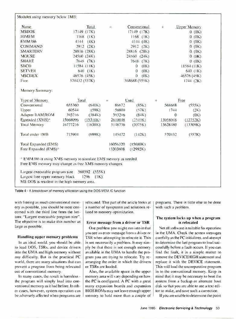
Modules using memory below 1MB:
Name Total Conventional Upper MemoryMSDOS 17149 (17K) 17149 (17K) 0 (OK)HIMEM 1168 (1K) 1168 (1K) 0 (OK)EMM386 4144 (4K) 4144 (4K) 0 (OK)COMMAND 2912 (2K) 2912 (2K) 0 (OK)SMARTDRV 28816 (28K) 28816 (28K) 0 (OK)MOUSE 24560 (24K) 24560 (24K) 0 (OK)SHARE 7648 (7K) 7648 (7K) 0 (OK)SBCD 11584 (11K) 0 (OK) 11584 (11K)SETVER 640 (1K) 0 (OK) 640 (1K)MSCDEX 46576 (45K) 0 (OK) 46576 (45K)Free 570432 (557K) 568688 (555K) 1744 (2K)
Memory Summary:
Type of Memory Total Used FreeConventional 655360 (640K) 86672 (85K) 568688 (555K)Upper 60544 (59K) 58800 (57K) 1744 (2K)Adapter RAM/ROM 393216 (384K) 393216 (84K) 0 (OK)Extended (XMS)* 15668096 (15310K) 2610048 (2549K) 13058048 (12752K)Total Memory 16777216 (1638K) 3148736 (3075K) 13628480 (13309K)
Total under IMB 715904 (699K) 145472 (142K) 570432 (557K)
Total Expanded (EMS) 16056320 (15680K)Free Expanded (EMS)* 13303808 (12992K)
* EMM386 is using XMS memory to simulate EMS memory as needed.Free EMS memory may change as free XMS memory changes.
Largest executable program size 568592 (555K)Largest free upper memory block 1296 (1K)MS-DOS is resident in the high memory area.
Table 4 - A breakdown of memory utilization using the DOS MEM /C function
with freeing as much conventional mem-ory as possible, you should be most con-cerned with the third line from the bot-tom; "Largest executable program size".The objective is to make this number aslarge as possible.
Handling upper memory problemsIn an ideal world, you should be able
to load DOS, TSRs, and device driversinto the UMA and high memory withoutany difficulty. But in the practical PCworld, there are many situations that canprevent a program from being relocatedout of conventional memory.
In many cases, the result is harmless -the program will simply load into con-ventional memory as it had before. In oth-er cases, however, system operation canbe adversely affected when programs are
relocated. This part of the article looks ata number of symptoms and solutions re-lated to memory optimization.
Error message from a driver or TSROne problem you might run into is that
you see an error message from a driver orTSR when attempting to relocate it. Thisis not necessarily a problem. It may sim-ply be that there is not enough memoryavailable in the UMA to handle the pro-gram you are trying to relocate. Try re-arranging the order in which the driversor TSRs are loaded.
Also, the available space in the uppermemory area will vary depending on howthe PC is configured. A PC with a greatmany expansion boards and expansionBIOS ROMs may not leave enough uppermemory to hold more than a couple of
programs. There is little else to be donewith such a problem.
The system locks up when a programis relocated
Not all software is suitable for operationin the UMA. Check the screen messagescarefully as the PC initializes, and attemptto determine the last program to load suc-cessfully before a fault occurs. If you canfind the fault, it is a simple matter toremove the DEVICEHIGH statement andreplace it with the DEVICE statement.This will load the uncooperative programin to the conventional memory. Keep inmind that it may be necessary to boot thesystem from a backup or alternate bootdisk so that you are able to use a text edi-tor to make, and save such a correction.
If you are unable to determine the point
June 1995 Electronic Servicing & Technology 53

at which the system locks up, start withthe last DEVICEHIGH statement in theCONFIG.SYS file and change each oneto DEVICE. Reboot the PC after eachchange is made. The last line to bechanged before system operation returns,is the problem. You can then leave thatline (to load into conventional memory)and return all subsequent lines to theDEVICEHIGH function.
A device drive fails to load in UMAYou may find that a device driver small
enough for the available UMA fails toload there. Some device drivers expandwhen they are loaded into memory. Inmost cases, the program will be loadedinto conventional memory. You can findthe actual amount of space a driver needsby allowing the driver to load into con-ventional memory, then using the MEM/C command to see the file and its corre-sponding file size-this will be the trueamount of memory needed by the driver.You can then try loading the driver withDEVICEHIGH using its size= switch.
Erratic program operation in UMAYou may encounter a situation in which
a program works erratically or improper-ly when loaded into the UMA. There aresome device drivers that simply do notwork well (or at all) in the UMA. It couldbe that the program needs a certain amountof memory above it, or the driver does notrecognize addresses in the UMA. In eithercase, the offending program should beloaded into conventional memory. If theoffending program is being loaded fromCONFIG.SYS, change its DEVICEHIGHstatement to DEVICE. If the problem isoccurring in AUTOEXEC.BAT, removethe loadhigh (or 1h) statement.
Nothing being loaded into UMAA situation may occur where nothing is
being loaded into the UMA. You can seethis by looking at the MEM report.Chances are that you have missed a con-figuration step which is preventing yoursystem from using the UMA. Check thefollowing items. First, check CONFIG-.SYS to see that the dos=umb or dos=umb,high statement is included after thememory managers are loaded.
Second, check that HIMEM and EMM-386 are loaded using the DEVICE state-ment rather than the DEVICEHIGH
statement. HIMEM should be loaded be-fore EMM386. Also see that the EMM-386 entry is using the noems or ramswitch. This configuration should enableuse of the UMA. At this point, simplymake sure that you are using DEVICE -HIGH statements for any CONFIG.SYSdevice drivers to be loaded in the UMA,and LOADHIGH statements for anyAUTOEXEC.BAT device drivers.
ConclusionConventional memory is perhaps the
most important and contested area ofmemory in any PC. The large number ofpowerful peripherals and utilities nowavailable for PCs is placing an ever -greaterburden on the first 640KB of system RAM.By freeing conventional memory, you areable to run larger and more complex pro-grams. This article is intended to explainthe concepts of system memory, and showyou some practical techniques for stream-lining your conventional memory.
Reprinted from Nov/Dec 94 issue ofThe PC Toolbox. Copyright 1994 by Dy-namic Learning Systems. All rights re-served worldwide.
"First in Quality, Service and Delivery"
REMIUMPARTS+'ELECTRONICS COMPANY
THE RIGHT CHOICEfor ELECTRONIC REPLACEMENT
PARTS & ACCESSORIES
1-800-558-9572or for 24 hour ordering FAX 1-800-887-2727
P.O. Box 28 Whitewater, WI 53190
Computer Monitor TesterPrice:
$295.00+$5.(x) S&H
Includesbattery,
AC adapter,Mac adapterand 120 day
warrantyFinally, a low cost way of getting into the monitor repair business. Test andrepair computer monitors with speed and accuracy. The "Checker 12" is aneasy to operate. hand held, battery, or AC operated computer color moni-tor pattern generator. With its support of CGA ( I5.75khz), EGA (22khz)MACH (35khz), and VGA modes 1,2,3 (3 I .5khz) 800X600 (35khz,1024X768 interlaced (35khz), 1024X768 non -interlaced & 1024X768N1with sync on Green (48khz), you can easily checkout a monitor in all ofits' modes. With its' single mode switch, you know exactly what type ofmonitor you are testing. Its' front panel color pictures show just what youshould be seeing on the monitor under test. You can quickly tell if themonitor is a VGA. SVGA, or a SVGA/NI. The "Checker 12" providesvarious test patterns for VGA monitors. X -hatch, for size and linearity andconvergence set-up. White screen. for purity and CRT burn evaluation.Color bars and 8 step gray scale for color tracking and balance. There isalso a single color mode that allows Ibr single color channel operation.
Computer and Monitor Maintenance1-800-466-4411 404-662-5633
We also have the Checker VI. a six port stand-alone VGA (640X48(1)test pattern generator. No computer required. Just $249.95.
54 Electronic Servicing & Technology June 1995
Circle (22) on Reply Card

Test YourElectronicsKnowledgeAnswers to the quiz(from page 30)
1. D (I know, in audio speak it iscalled "rms power" even though thatterm doesn't make any sense).
2. 7W (Regardless of whether the re-sistors are in series, parallel, or series/parallel, the total power is found byadding the individual powers).
3. B (It is the same as making the con-trol grid more negative).
4. A (In other words, the control gridshould be negative with respect to thecathode).
5. Power factor equals the cosine ofthe phase angle.
PF = Cos(38°) = 82.7%, or 0.827
6.5 + j8 (To write the conjugate of acomplex number it is only necessary tochange the sign of the j term).
7. This equation is hard to find whenyou need it:
Np Zp2
Ns - Zs2
8. Dynamic range (By definition).
9. B (There are eight symbols in theoctal counting system: 0 through 7.There is no symbol 8 in the octal sys-tem).
10. The equation for capacitive reac-tance is:
1
XC 2nfC
Solve that equation for f and you get:1
f = 2ficC
Plug in the values and you get a littleover 2000kHz.
MCM Electronics is yourcomprehensive source for all of yourservice needs. Our inventory of over21,000 stocked items includes testequipment from Fluke, B+K, Hitachi,Leader and TENMA. There is also ahuge selection of repair parts includingbelts, heads and mechanisms for mostbrand name consumer electronicequipment and over 10,000semiconductors, a broad selection ofspecialized tools, technician aids andmuch more. Discover for yourself theMCM Electronics difference, call foryour free 332 page catalog today.
MCM Electronics is aPremier RCA/GE
D stributor
Call Toll Free
Technical questions, 1 -800 -543 -TECH (832
ORGANIZE AND PROTECT YOUR COPIES OF
ES&TNow there's an easy way to organized and keep copies of your favorite magazine readily available for
future reference.These custom-made titled cases and binders are ideal to protect your valuable copies from damage.They're designed to hold a years issues (may vary with issue sizes). constructed with reinforced board
and covered with durable leather like material in red, title is hot -stamped in gold, cases are V -notchedfor easy access, binders have specia spring mechanism to hold individual rods which easily snap in.
Each binder s $9.95 plus $1 S & H ($2.50 outside the US)Cases: 1-S8.95 3- S24.95 6-$45.95 Binders: 1-S11.25 3-S31.85 6-5E0.75
Mail all correspondence to:Electronic Servicing & Technology.
Jesse Jones Industries, Dept. 95EST, 499 East Erie Avenue, Phil., PA 19134CHARGE ORDERS: (Minimum $15): AMEX. VISA, MC, DC accepted. Senc card name. #, Exp. date
Allow 4 to 6 weeks delivery'
Call TOLL FREE 7 days, 24 hours 1-800-825-6690
MCM ElectronicssmThe Only Source You'll Ever Need
iporrA
:RfiMCM ELECTRONIC CPTP LO650 CONGRESS PARK OR.CENTERVILLE. 01- 45459-407
A PREMIER Company Hou M -F 7a.m.- ..
SA 9a.m.- 6p.m. EST
Oat Fast Delyery From Our Distribuion Centers Near Dayton, 01 and RCM NV! CODE: ES82iCircle (31) on Reply Card
Jure 1995 Electra -11c Servicing & Technology 55
Computer Corner
Reach out and touch someoneBy David F. Norman
Small business owners already knowabout the telephone. While we cuss it andhate it when it rings at an inconvenienttime, we know we simply cannot survivein business without it. The phone allowsus to be reached by our customers and itallows us to yell at a supplier thousandsof miles away when shipments don't ar-rive as scheduled.
From ordering a pizza when lunch isgoing to be eaten with one glove on be-cause you are too busy to stop, to makingairline reservations for a trade show, theuses of the phone are simply too numer-ous to mention. However, lately there isanother use for the phone which a lot ofbusinessmen have not considered: put-ting your computer system "on-line."
Connecting the computer to thephone system
Few computers are sold now withouta modem-a coined word which meansMOdulator/DEModulator-a devicewhich lets your computer "talk" to othercomputers over telephone lines. (For thenitpickers, it should be stated that mo-dems are also used for other types of ac-cess, but regular telephone lines are themost common types of connection.)
Proprietary software-such as thatused by franchised operations-has longused automatic dial -up to update cata-logs, ask for orders, and send invoices fororders polled from the system. This pro-cess is usually so transparent and takesplace at such odd hours that no-one paysit much attention unless it doesn't work.But that is only one of the many possibleuses of a computer and a modem.
As we move very quickly into theinformation age, the number of reasons toget with it and get online continue to grow.Everyone knows about America Onlineand Compuserve. Everywhere you lookin the paper, you hear about the Internetand the Information Superhighway. Infact, we hear about it so often, our eyes
Norman is an independent computer consultant.
sometimes glaze over. But don't let thatoverexposure turn you off. There are a lotof reasons for all that hoopla, and someof them are good news for you personal-ly and for your business. The next fewinstallments of Computer Corner willdeal with going online with a computer.Pardon me if I cover what you alreadyknow; the idea is to give you ideas.
Local bulletin boardsLocal BBS Electronic Bulletin Boards
(BBS) are not at all new. As soon as some-one learned to connect a computer to amodem and call someone else over thetelephone lines, BBS's were born. Formany years, BBS services were mostlyeither hobbies or used for special servicessuch as product support.
Protocols for transferring files overthe wires were invented and improveduntil absolute reliability was a reality.Fiber optics improved the telephone ser-vice and speeds of transfers began to takegiant leaps ahead. The original modems
might transfer files at 50 or 100 baud.This translates out to five to ten charac-ters per second. Some of us can typemuch faster than that.
Now speeds of 14,400 bps are the normand 28,800 is rapidly becoming the stan-dard. How fast modems will get is stillunknown. With error correction and com-pression built into current modems,throughput-the actual speed at whichdata is transferred-can now exceed40,000 bps or roughly 4000 characters persecond. To put that into real world terms,I could send this document in only a cou-ple of seconds or less to another comput-er with a fast modem and a clean phoneline. Just plain beats mailing it.
It costs me just under a buck to mail asmall manuscript and a disk anywhere inthe U.S. I can transfer the same informa-tion for less than thirty cents anywhere inthe U.S. and know that it got there in per-fect condition. Why waste time faxing adocument and have it look nasty when itgets there, when I can send it directly to
56 Electronic Servicing & Technology June 1995

a computer where it can be printed out ona laser printer and look perfect? Ofcourse, the fax machine will be around fora long time yet. Sending computer gen-erated documents is one thing, scanninga document into a computer and faxingit that way is something else.
The cost of a bulletin boardComputers and modems can be used
to move information very quickly, butthere is more. National and local BBSservices-not counting America Onlineand Compuserve and their competi-tors-are a big business. There are stilla lot of free BBS services around, butsomeone has to pay for the upkeep. If youhave multiple phone lines to your placeof business, you know that each monththere is a big flat fee-even if the phonedidn't ring all month.
A medium sized BBS has from 10 to20 lines plus the upkeep on the equipmentto which they are connected. Unless theBBS operator is pretty well off, the billshave to be paid from BBS revenue. Feesfrom users pay some or all of the cost andother revenue comes from advertisers.This is where several opportunities existfor the electronic servicing dealer.
Working with an existing BBSFor modest fees-usually only a few
bucks a month-you can offer your prod-ucts and services to a technically orient-ed market. If the BBS provides a lot ofservice to its users, the users tend to befiercely loyal-not only to the BBS butto the advertisers who sponsor it and helpkeep user fees low.
Another reason for supporting a BBSas an advertiser is the support you can pro-vide for your customers. If I have a prob-lem with something in the middle of thenight, whenever possible I send the sup-porting party an E -Mail message. Thenthe support people can either call me orgive me an answer to my question byreturn E -Mail. It works!
If you check your answering machinein the morning, you can figure on beingtied up for an hour or so just chatting onthe phone. When the solution you provideto your customer may be as simple as:"Unplug the unit from the wall. Wait for30 minutes and then plug it in again andreprogram the clock and channel setup. If
that doesn't fix it, bring it in and we willput it on the bench." Short, sweet, and tothe point. If you had this kind of infor-mation available on a BBS, it wouldn'twaste time-yours or theirs.
Announcements of sales and specialofferings are easy to upload to the BBS andas your online customer base grows, youwill probably build an E -Mail list of "hot"prospects for your services and wares.
Talk to a local BBS operator or "sysop"and ask if he has any ideas as to how yourbusiness might be improved by his par-ticular operation. You spend lots of mon-ey for advertising of all sorts. Electronicadvertising is cheap and effective. SomeBBS's even take orders for products intheir "Electronic Malls."
Setting up a BBSIf your business is directly involved
with computer sales or service, your op-portunities are even greater. You mighteven want to consider setting up your ownBBS. What do you need to access a BBS?If you have a computer with a modem,you probably already have everythingyou need. Microsoft Windows comeswith a basic communications programcalled, appropriately, Terminal.
Mustang Software makes a full line ofcommunications software. Wildcat BBSsoftware by Mustang is running on BBS'sall over the world. They even offer ashareware version-which has most ofthe bells and whistles of the full -featuredversion and you can try it before you buyit. Whether you are running DOS or Win-dows, Mustang makes a communicationspackage for your operation. You can "testdrive" Q -Modem for DOS and evendownload it from Mustang's BBS (805-873- 2400) and all it costs you is a littlephone time. Be warned, however, the filesfor Q -Modem are big and you need to berunning at 9600 bps or higher to down-load it in any reasonable time.
For the last few months, I have beenrunning Q -Modem for Windows. What-ever you want in a comm package, thisone has it. Dozens of terminal emulations-so your computer can properly "talk"to the distant computer, even fancy main-frames-automatic dialers and "scripts"which let you automate your connections.The program's script programming lan-guage can get pretty complex, but most
of us don't have to do anything other thanturn on the "Quicklearn" facility and actjust like we are recording a macro for anyother program.
The software comes with a "host"script which sets up a mini-BBS on yourcomputer so that someone can call youand upload or download files if you allowthem to do so. If you are worried aboutaccess to your system, you can set it upas a closed, "callback" BBS.
Before anyone can access your com-puter when it is set up as a callback sys-tem, you have to first enter their loginname, their password, and their modem'snumber. When they ring into your boardand login, the system hangs up and thencalls their modem back. When they an-swer-which can be automated by ascript-they have to give their passwordagain and only then are they permitted toupload or download files. Simple. butfairly impressive security.
Q -Modem can also use RlPscrip if theremote system supports it. RlPscrip allowsyou to use a mouse for point and shoot asyou navigate through the BBS menus. Forthose of us addicted to the little rodents,this is a neat idea whose time has come.Last and maybe least, the program has afax facility. This would be a much biggerdeal except that most high -end word -processors do the same thing, better.
Next time on Computer Corner, we willdiscuss some of the business opportuni-ties offered by increasingly less ex-pensive Internet access, and speaking ofE -Mail, my address is:[email protected].
June 1995 Electronic Servicing & Technology 57

Video Corner
Servicing remote controltransmitters
Ricks Ilall
One of the more profitable products thatI service in my service center is remotecontrol transmitters. That is, consideringthe amount of time I have to put into ser-vicing a remote unit, the amount I chargefor this service, and the success rate, thereturn I receive is very good.
A typical repair, if it is feasible on aremote, takes about 20 minutes. If it takesmuch longer than that, it isn't worth it. I
find that my success rate on remotes isabout the same as for TVs, and much bet-ter than for VCRs and stereos. For this Ican charge about one-fourth the amountthat a customer would have to pay for anew unit, if the customer had to buy a newremote from the original manufacturer.
You might say, that the customer couldjust buy a universal remote for near whatI would charge to service one. That is pos-sibly true. However, most of today's TVand VCR remotes have special functionssuch as menu, setup, sleep, and tracking.It isn't always possible to find a remoteunit that performs all of those specialfunctions. Moreover, the customer iscomfortable with the remote and wouldusually rather spend a reasonable amountto fix their remote than to learn how tooperate a universal product.
The remote testerA remote control unit tester is a must
for faster and easier remote servicing, notone of those card indicators that gives offa reddish glow when you hold a remotenear it in subdued light. I quit using thosecards quite some time ago. They workfine, but they require the use of both handsand I found them hard to see unless thelight in the room was dim.
There are some store bought testers onthe market. I have seen one in an elec-tronics catalog, for example, that is in theform of a pen. That unit might be OK for
Hall is the owner and chief technician at Hall's TV inPrenti.s. NIS
IR
RECEIVER
+9VDC
PULSE
GROUND
Figure 1. If you have a discarded TV or VCR waiting to be scrapped, you may be able to reclaimthe IR receiver. Many of them have connections as shown here. IR receivers are also availableinexpensively at stores that sell electronics components.
testing an IR signal inside a VCR, but Idon't use one for remote testing, for thesame reason that I don't like the cardtester. You have to hold down a buttonwith one hand and the remote in the other.
The best remote tester I have used isone that I built myself, and it didn't costanything. I used an old IR receiver froma discarded TV set, a box from an old an-tenna booster power supply, a power sup-ply from an old Atari game, and an LEDfrom an old VCR. I also built a handycompact model using Radio Shack parts(Table 1). An article on those units waspublished in the March 1993 issue ofElectronic Servicing & Technology.
The diagrams showing the IR receiv-er, and the construction of the tester, arereproduced here as Figures 1 and 2 foryour convenience. With this tester, youcan check output from a remote from clearacross the room. You can mount or set theunit on a shelf, plug it into the ac and itwill be on and ready whenever you needit, and you don't have to dim the lights orhold the remote transmitter close to thetester in order to get an indication.
You could build another unit, and runit off a 9V battery to take along on calls.My wife works in the service center mostevenings while I am out on calls, and sheuses the tester when a customer comes in
and thinks that his remote needs batter-ies. The customer can see for himselfwhether or not the remote works.
Bad solder connectionsThe most frequent cause of remote fail-
ures is bad solder connections, especial-ly on the leads of the crystal, the LED andany other heavy parts on the circuit board.Many times, the broken lead of the crys-tal will be broken off very short.
I desolder the crystal and scrape aroundthe broken lead with a razor knife to cleanoff as much of the broken lead as possi-ble. Then I strip an old TV or VCR linecord, take one of those thin strands of cop-per wire, and wrap it around the brokenlead and solder. After reinstalling thecrystal in the circuit board, I glue it to theboard with some silicone rubber. This willhelp absorb the shock, and the crystal willnot shake loose again. Most manufactur-ers are now using some kind of adhesive,or sticking the crystal down with two-sid-ed tape so broken crystal leads will prob-ably be less common in the years to come.
Spilled liquidsThe next most common problem I en-
counter in remotes is the spillage of cof-fee, tea or soft drinks into the unit. In most
58 Electronic Servicing & Technology June 1995

Figure 2. A simple circuit, as shown here, can put an IR receiver to work as an IR remote transmitter tester.
Table 1IR Receiver 276-137High Brightness LED 276-066Case (Box) 270-2939V Battery Clip 270-325SPST Toggle Switch 275-624
Table 1. You can build the IR tester circuit inFigure 2 using the bill of materials shown here.The case has a compartment with a door thatyou remove to insert a 9V battery.
cases, the customer isn't even aware thatsomething has been spilled into the re-mote. The best way to fix this problem isto take the unit apart and give it a goodbath. Don't use an aerosol contact clean-er such as alcohol, Blue Shower, etc., toclean the conductive rubber pads. I ruinedseveral remote -control transmitters try-ing to do this, and it just doesn't work.
I use a household cleaner called Whis-tle Cleaner. It is a cleaner/degreaser, andworks quite well. I'm sure that any othercleaner of that type, such as 409, GlassPlus, Fantastic, or any of the many simi-lar products would also work. But try anyof them on a remote you're not too par-ticular about first, to be sure that theywon't damage the unit.
Just spray down the circuit board, therubber conductive pad, and the top coverof the remote unit. Use a soft toothbrush,and scrub it down well. Be particularlycareful to clean the circuit board where the
conductive rubber pad meets the board.Usually there will be a buildup of drinkand crumbs around the holes in the topcover. Clean this well with a brush so thepushbuttons can move freely.
Next, rinse the unit well and shake offthe excess water. The best way I havefound to dry the parts before reassemblyis to use a vacuum cleaner in the blowingmode. Turn the vacuum on before youstart the cleaning and by the time you areready to dry, the air will be warm.
The air from my vacuum is fairlystrong, but not as powerful as the air-stream from a compressor hose, whichmight blow parts around. Also, the air isvery dry, and after it has run for about fiveminutes it is slightly warm. I find that thisdries the parts much faster than using aheat gun. Also if you use a heat gun yourun the risk of overheating parts.
Other failure modesSome of the other fixes are broken
wires, broken circuit board traces andbroken battery terminals. There is an old-er Zenith IR remote that doesn't use acrystal. This unit is based on a tuned cir-cuit, and has an adjustment on it. When Iencounter this unit, I try tuning the unit alittle at a time, then try it on a Zenith TV,until it works. I have found that in aboutninety percent of the cases, if there is out-put from the remote transmitter, it willoperate the product's remote receiver.
In the case of the Zenith tunable remote
control, and one NAP unit, there are occa-sions when it will not operate the TV set,even though you will see an indication ofoutput on the remote control tester. In thecase of the NAP remote, the LED on thetester will flash very slowly. If you seethis slow flash, you will know that the leadon the crystal is broken.
Save those old remote control unitsIt is a good idea to save all your old re-
mote controls from discarded sets, andany remotes left at the service center, It isusually not worth the trouble to order re-placement components for remote con-trol units, so things like battery covers,top covers, bottom covers, IR outputLEDs, LED lenses, crystals, batteries, ter-minals and such come in handy.
UHF transmitters can be serviced tooNinety-nine percent of the remotes that
are brought in for service today are theIR type. I have, however, worked on a fewof the UHF type that work with satellitesystems. The IR tester won't do you anygood on those, but a large percentage ofthose can be serviced, too.
Considering their small size and lowcost, it might seem at first glance that re-mote control units just aren't worth both-ering with, and that they should simply bediscarded when they fail. But as this arti-cle demonstrates, remote control trans-mitters can be serviced profitably, keep-ing many of them out of the landfill.
June 1995 Electronic Servicing & Technology 59

What Do You Know About Electronics?Motor speed control and load linesBy Sam Wilson (WA8RMS)
In a previous issue we reviewed theconstant -current supply as it applies to dcmotors. Remember that a constant volt-age is applied to a dc motor if you want aconstant speed. A constant current is ap-plied if you want a constant torque. Thisinstallment of WDYKAE? will look atanother example of how a constant -cur-rent generator is used.
Achieving constant currentFigure 1 shows a traditional differen-
tial amplifier with a constant -current di-ode supplying the two halves of the cir-cuit. We have reviewed the constant -cur-rent diode before. It can be made with aJFET having the gate tied to a seriessource resistor.
There are a number of other ways to getthe constant -current input to the differen-tial amplifier. Textbooks tell us that theconstant current is necessary so that thesum of the transistor currents will be aconstant value. Textbooks also say thatthe constant current can be obtained byusing a high value of resistance. The ques-tion is: How can a high resistance give usa constant current? Figure 2 tells the story.
This graph shows the relationship be-tween resistance and current in a circuitthat consists of a 0S2 to 6000 variable re-sistor in series with a 500Q resistor. Onlyfive points are used to show the relation-ship between resistance and current. Thesteep downward slope indicates that thisis not a constant -current relationship. Ifthe current were constant, the current vsvoltage curve would be a horizontal line.On the same graph, the current/resistancerelationship with the fixed resistanceincreased to 50000s is shown. As shownby the decreased slope, this circuit is near-er to a constant -current relationship.
Whoa! Wait just a darn minute! The sec-ond curve only shows the more constantcurrent/resistance relationship when thecircuit has a greatly reduced current.
Wilson is the electronics theory consultant for ES&T.
ConstantCurrentDiode
V
Figure 1. A traditional differential amplifier with a constant -current diode supplying the two halvesof the circuit.
What we want to see is a constant cur-rent/resistance curve when the currentstarts at the same point.
Getting higher constant currentNot to worry. Look at the graph in Fig-
ure 3. If the applied voltage is raised to150V, the initial current starts with thesame current value as the first graph:30mA The graph in Figure 3 shows amore -nearly constant current relation-ship. However, it was obtained by in-creasing the applied voltage.
Actually, the second graph in Figure 2is closer to what we are looking for. It ac-complishes a better constant -current rela-tionship with the lower voltage. That isthe better choice if the amplifiers can op-erate at the reduced current.
BIFET works betterWe established at the outset that the cir-
cuit in Figure 1 is a traditional differen-tial amplifier. We're talking about the ear-liest 741 op amp input circuit. That circuitworks much better if you trade in the bipo-lar transistors for "BIFET" (bipolar field-effect transistor) amplifiers. (Figure I in-
set.) You will also see the newer versionreferred to as BICMOS. Other favoriteterminology is also used.
The point is this: by using a FET to con-trol the base current of the bipolar transis-tors you get a high -impedance input to thecircuit, and to the op amp. The high inputimpedance translates to the fact that thecircuit delivering a signal to the inputdoesn't have to supply signal power. Read"signal power" to mean signal current.So, you get the advantage of the high (in-put) impedance FET and the higher -cur-rent controlled amplifier.
Picking more nit out of theoryWhen you mention Newton's Law of
Gravity out loud in some circles, you'reinviting the statement: "Einstein's Law ofGravity has replaced Newton's GravityLaw". Let's take a look at the difference.
Newton's law of gravity is written inequation form as follows:
F = mim2/d2
where F is the force of attractionbetween bodies with masses Ml, and M2,and d is the distance between the masses.A constant of proportionality is usually
60 Electronic Servicing & Technology June 1995

500
RL
RL0 30
=-T 15V 0 TO 600OHMS
150 23300 18.8450 15.8600 13.E
30
26
20
16 -
10
6
R = 6000HMS
R = 60000HMS
1010 2010 3010 4001 6016010 6010
Figure 2. The upper curve on this graph shows the relationshipbetween resistance and current in a circuit that consists of a OD to6005I variable resistor in series with a 5000 resistor. The lower curveshows the current/resistance relationship with the fixed resistanceincreased to 500SIs. As shown by the decreased slope, this circuit isnearer to a constant -current relationship.
included to take care of different medi-ums between the masses.
Grinding in the effect of relativity,Einstein's Law of Gravity is:
F = m imid2.00000016
If you are dealing with heavy objects ata great distance-like planets-Einsteinhas it. However, if you are working withtwo Ned balls separated by a distance ofone centimeter, defer to Newton's Law.Einstein's Law did not replace Newton'sLaw, it increased the accuracy of New-ton's Law when dealing with large valuesof mass and distance.
That infrared thingIt was student Joe Feusner of Wichita,
KS who asked about the Radio Shack in-frared detector. The question is, "Howdoes it work?" His instructor, David T.Ronan, in Norcross, GA, passed thatquestion on to me. I, in turn, asked thereaders of this column how it works.
Many thanks to the readers who sentcircuits for IR detectors. But, so far notone reader was able to explain the Radio
6000
RL
RL0 30
-='50V 0 TO 600OHMS
150 29.1300 28.3450 27.5600 26.7
30
26 -
20
16
10
5
R = 60000HMS, V = 160V
R = 6000HMS, V = 16V
100 2013 3610 4010 600 600
Figure 3. If the voltage applied to the circuit of Figure 2 is raised to 150V,the initial current starts with the same current value as the first graph.30mA. This graph shows a more -nearly constant current relationshipHowever, it was obtained by increasing the applied voltage.
Shack device that changes color whenexposed to infrared light. I managed to gothrough chemistry in college without tak-ing the lab. I had to get special permis-sion from a doctor to duck out of that lab.I passed the course with a B, but I can'tsay I know much about the subject. How-ever, I don't feel too bad about it. Noneof my readers have explained how itworks. Neither did the guy who makeskeys at Ace Hardware.
So, let me ask one more time-Doesanyone know how the Radio Shack IRdetector works? Send me an explanationand I'll send you a gift.
Leak detectorsQuestion: How do they use electronics
to detect very small leaks in pneumaticsystems?
Answer: They use ultrasonic detectors.Those detectors can pick up the very lowvolume of ultrasonic sound the leakinggas makes.
If you are thinking of taking the CETtest and you want the Industrial Elec-
tronics option, ISCET is using the How-ard Sams book titled "Industrial Elec-tronics for Technicians" by J.A. Sam Wil-son and Joseph Risse. Howard Sams sellsthe book under the publisher name"Prompt".You can get the book from:ISCET, 2708 West Berry Street, Ft.Worth, TX 76109-2356. Be sure theysend you the correction sheet!
A different load line problemWe have reviewed load lines in previ-
ous issues. Let's start this discussion witha typical load line problem that will serveas a review. We will then review a differ-ent kind of problem. Figure 4 shows atransistor connected across a Theveninequivalent generator. It is presumed thatthe generator represents a more compli-cated circuit where the transistor is actu-ally connected. The applied voltage is10V and the current is known to be 5mA.The base current has been adjusted toequal 60pA.
The problem is: what is the voltageacross the transistor and what is the cur -
June 1995 Electronic Servicing & Technology 61

rent through the transistor? To solve thisproblem, start by locating two points onthe graph: the open -circuit voltage of 10Vand the short-circuit current equal to10V/2K0 = 5mA. Draw the load linebetween those two points. At the pointwhere the load line crosses the 60pA basecurrent curve, draw a vertical broken linedown to the voltage axis, and horizontalbroken line over to the current axis. Thecurrent is 3.8mA, and the voltage acrossthe transistor is 2.45V
Solving for base bias currentNow let's try a different type of prob-
lem. Refer to Figure 5. Again, a transis-tor is connected across an equivalentThevenin generator. The short-circuitcurrent is 7.5V/12500s = 6mA. The opencircuit voltage is 7.5V. The load line isdrawn using those values.
The problem shows that there is 5Vacross the transistor. The question is:What is the base bias current? To solvethe problem, project a line up from the5V point to the point where it strikesthe load line. That point is on the 40pAcurve, so the base current must be 40pAin order for the voltage across the tran-sistor to be 5V.
zw0
IflE
Your Ticket TosyTcicii7QQ
%AA,' AM7Over 28,000 technicians have gained admit-tance worldwide as certified professionals.Let your ticket start opening doors for you.
ISCET offers Journeyman certification inConsumer Electronics, Industrial, Medical,Communications, Radar, Computer andVideo. For more information, contact theInternational Society of Certified Electro-nics Technicians, 2708 West Berry Street.Fort Worth, TX 76109; (817) 921-9101.Name
Address
City
State Zip
Send material about ISCET andbecoming certified.
Send one "Study Guide for theAssociate Level CET Test." En-closed is $10 (inc. postage).
Figure 4. The transistor is connected across a Thevenin equivalent generator. The applied volt-age is 10V and the current is known to be 5mA. The base current has been adjusted to equal60pA. You can use a load -line technique to determine the voltage across the transistor and thecurrent through the transistor.
Figure 5. Here's an example of using a load line to solve for base bias current. To solve thisproblem, project a line up from the 5V point to the point where it strikes the load line. That pointis on the 40pA curve. So the base current must be 40pA in order for the voltage across thetransistor to be 5V.
62 Electronic Servicing & Technology June 1995

LiteratureIEEE 1284
A new color brochure is available from3M Electronic Products Division describ-ing their line of IEEE 1284 compliantproducts. The newly adopted IEEE1284standard for high-speed peripheral -to -hostcommunications defines a new bi-direc-tional signaling method and establishesstandards for the cable and connectorsneeded to attach peripherals to a host Per-sonal Computer.
The 42 -page brochure provides prod-uct features, color photographs and tech-nical drawings of the company's IEEE1284 boardmount and wiremount con-nectors, 1284 cables, compliant assem-blies, adapters, and accessory hardware.The brochure also details the physical,electrical, and environmental characteris-tics of the compliant products.
Circle (55) on Reply Card
Solvent guide updateAn all -new solvent guide update is now
available from Dynaloy, Inc., a manufac-turer of specialty chemicals and solventsserving such industries as telecommuni-cations, computers, electronics, plasticsprocessing/molding, automotive, avion-ics/aerospace, medical, audio/video, con-verting and laminating.
The one -page flyer is an update to themain Solvent Selection Guide, and de-scribes a new line of safety solvents forsolving industries' concerns of health,safety, disposal, and the environment.
Applications for these solvents includegeneral cleaning and degreasing ; clean-
ing of urethane and isocyanate residuesfrom equipment and molds; the removalof mold release residue from plasticmolded parts; cleaning of silicone oils anduncured silicone polymers from moldsand equipment; and the cleaning and de -fluxing of printed circuit boards.
Circle (56) on Reply Card
Test accessories catalogITT Pomona's 1995 Electronic Test
Accessories Catalog contains 172 pagesof more than 3,800 specialized productsarranged in an easy -to -read format in-cluding helpful selection guides. All ofthese accessories are designed to opti-mize the performance of test equipmentand to guarantee consistently reliable testresults, according to the company.
Useful as a resource, companion pieceto equipment from Hewlett-Packard, Tek-tronix, Fluke and other leading manufac-turers, the catalog includes short tutorialsections such as, "Selecting the RightScope Probe" and "Extending YourDMM'S Capability."
Featured products include: a new seriesof 30-450 MHz oscilloscope probeswhich integrate an all -new surface mountdevice (SMD) circuit, developed for usein testing today's highest -performanceICs; new IC test clips including a 240 -pinversion for MC68360 devices; sealedpolycarbonate and die-cast aluminumenclosures; a pocket -sized logic scopeprobe; ultra -thin micrograbbers for test-ing fine -pitch (0.25 mil) ICs; a program-mable IC/socket test switch test adapter;high -voltage and plug -on specialty probes,
and a new line of ESD accessories andtest/service kits.
Circle (57) on Reply Card
Electronics product catalogGalco Industrial Electronics has re-
leased an updated, easy -to -use, productcatalog containing over 300,000 items inover 1 300 pages. These items are easilylocated through the use of either a com-prehensive product or manufacturer in-dex and each section features an individ-ual index for quick referencing.
The greatest enhancement to the com-pany's newly revised Full Line ProductCatalog is an all -new complete alpha-numeric listing of semiconductor partnumbers and their location within thesemiconductor section. Modificationshave also been made to many of the prod-uct lines in the semiconductor sectionincluding additional detailed technicalspecifications and data, 157 pages of newsemiconductor products, a fully revised,user-friendly section index, and more.
Many new product lines have been add-ed during 1994. Some of the new lines in-clude, Autocon/Dynapath, BEI, Bourns,Control Techniques Dart Controls, Elec-tromatic, Mallory and Thor Electronics.These new product line pages are locatedat the beginning of the appropriate cata-log section and are highlighted at the topof the corresponding section index. Thenew products are also featured in theproduct and manufacturer index locatedin the back of the catalog. All "New Prod-uct Pages" have been tabbed for quick andeasy reference.
Circle (58) on Reply Card
Technical supplies catalogNew from HMC is a detailed, fully -
illustrated buying guide of electronictools, test equipment and technical sup-plies for the assembly, testing and repair-ing of electronic products. This catalogcontains a large selection of brand -nameitems inc:uding precision hand tools, testinstruments, datacom/telecom equip-ment, tool kits, soldering/desoldering sys-tems, lamps and magnifiers, static controlproducts, industrial chemicals and adhe-sives, measurement and inspection in-struments, and work stations.
Circle (59) on Reply Card
June 1995 Electrolic Servicing & Technology 63

Business Corner
Leadership: A rare and valuablecommodityPart Four Political Leadership1{ John Ross
This magazine may seem like an unusu-al forum for a discussion about politicalleadership. With the exception of ourmembership in various organizations andour concerns about legislative moves,most of us have very little to do with polit-ical aspirations. Furthermore, most of usview political behavior, and thus, politi-cal leadership as an undesirable but un-avoidable part of organizational life.
Political leadership is everywhereHowever, the notion of political lead-
ership surrounds us and affects our ac-tions in a variety of ways. When we con-sider the leadership spectrum describedin previous articles, political leadershipbecomes difficult to place.
Certainly, transactions occur in the po-litical leadership arena. Just as politicalleadership tugs at and nudges the conceptof ethical leadership. In organizations,political behavior becomes evident whenconsidering the allocation of scarce re-sources, when evaluating personnel, dur-ing the setting of organizational goals,and during the making of decisions.
It becomes obvious, then, that individ-uals will manipulate organizational poli-tics to acquire, enhance, or to use powerand other resources in order to obtain adesired outcome in a given situation. Usu-ally, the situation will involve some typeof disagreement or uncertainty. Consid-ering the allocation of scarce resources,astute political behavior by one managermay garner more resources for his sectionwhile robbing resources from anothersection of the organization.
In terms of evaluation, the first manag-er may win a higher evaluation from hissuperior. The other manager may receive
Ross is a technical writer and microcomputer consultant forFt. Hay. State University. Hays. KS.
a message about his perceived lack of per-formance in the form of a lower eval-uation. As mentioned, political behavioralso comes into play during the goal -set-ting and decision -making processes.Individuals may shape organizationalgoals and decisions, so that not only theorganization benefits, but the individualbenefits as well. A manager or employeemay adamantly push for a new organiza-tional direction, knowing that he will gainpersonal rewards during implementation.
Methods of obtaining powerSome methods to obtain power include: Controlling information-providing
only parts of critical reports for organiza-tional review, omitting certain key ordamaging facts, and lies.
Controlling lines of communication-controlling access to individuals.
Using outside experts-justifying aposition or decision through the claimsmade by friendly, outside experts.
Controlling the agenda-keeping adecision off the agenda, extending dis-cussions so that everyone tires, or raisingtechnicalities about a proposal.
Game playing-being absent whencrucial, potentially disruptive decisionsare being made, pretending not to be inthe decision -making or leadership loop,leaking sensitive information, and show-ing favoritism to some, ignoring others.
Image building-maneuvering by in-dividuals so that they participate in onlythe successful projects, taking credit forthe work of others, exaggerating person-al accomplishments.
Building coalitions-urging others tojoin ranks before a controversial decisionhas to be made.
64 Electronic Servicing & Technology June 1995
Controlling decision parameters-defining the criteria or specifications bywhich a decision is made. In this way, theindividual may seem unbiased since hecan maintain some distance from the actu-al decision -making process.
Each one of the behaviors listed threat-ens the stability of the organization andundermines the ability of the leader. Un-fortunately, none of us can simply elimi-nate these behaviors, but, we can take spe-cific actions that will negate the effectsbehind these behaviors.
Countering political behaviorCountering political behavior in the
organization calls for the recognition ofpolitical behaviors. Indeed, recognizingthese behaviors, and the opportunity forthese behaviors to surface can allow thepolitical leader to anticipate certain ac-tions. With anticipation as a weapon,leaders may opt to enlarge and open com-munications to the entire organization, orproductively move to eliminate uncer-tainty. Instead of allowing rumors togrow, the political leader may make an-nouncements as decisions are made.
In the end, political leadership re-quires an awareness that leaders and fol-lowers play given roles, and an aware-ness that those roles change often. Theexchange of roles may occur over timeand with different political settings.
According to James McGregor Burns,leaders have a special role where theybecome activators, initiators, and mobi-lizers. The personal influence of a leaderflows in multiple directions, and bothvertically and horizontally. True leaderswill attempt to sort personal motivationsfrom the decisions that affect the direc-tion of the organization.
Moreover, true leaders will maintaincontact with ethical values while per-forming the transactions that are a neces-sary part of their daily activities. In thisway, these leaders create followers whohave the ability to become leaders. In-stead of maintaining a tight grip on polit-ical power, true leaders spread the power.keep organizational communicationshonest and open, and anticipate personaland organizational needs. All of this al-lows the leader to negate the effects ofpolitical behavior.
tCapitol-ize on
the opportunityto enrich your skills at the
1995 National ProfessionalElectronics Convention, July 31 -Aug. 5,
in Arlington, VA (Wash., DC). Programswill include: Hands-on Technical Training
Certification *Management SeminarsIndustry Trade Show
Register and pay by June 30 to$AVE UP TO $100 PER PERSON.
For a registration form or more information,rush the following to NESDA:
NameBusiness
AddressCity State
ZipPhone
National Electronics Service
NESDADealers Association, Inc.
2708 W. Berry St.Ft. Worth, TX 76109
(817) 921-9061
SAVETIME
For fast, accurate service,please remove the peeloff 'abet used to addressyour magazine, andattach it to the ReaderService Card, the AddressChange Card or to anycorrespondence yousend us regarding yoursubscription.
Mail AllCorrespondence To:Electronic Servicing &
Technology76 North BroadwayHicksville, NY 11801
SAVE TIME, MONEY, AND FRUSTRATION WITH...
ONE - SHOPPING!!!
There is ONLY ONE place to call!PHONE: 800-289-0300 or FAX: 800-289-0301
WITH OVER 1/4 MILLION LINE ITEMS, ALL IN ONE LOCATION!
YOU WOULD HAVE ONLY:r".", One purchase order to generate (no minimums) ^ One invoice to payr7- Qncshipment to receive (averaging a 90+% fill -rate)r-,* One backorder report to reconcile
(automatically mailed bi-weekiy with ETA's)
FACTORY AUTHORIZED FOR 16 MAJOR BRANDS!
SONY PANASONIC JVCSHARP PROSCAN* AIWA
ZENITH QUASAR DELCOTOSHIBA SCOTT HITACHI
TECHNICS RCA* EMERSONGE*
We also offer: A FREE or DISCOUNTED FREIGHT program. SAME DAYSHIPPING for orders in by 2:30 P.M. (P.S.T.), NO HANDLING CHARGES,and the linest RESEARCH department anywhere!
FOR THE MOST PARTS AND THE FASTEST SERVICE...
COUNT ON agandrewselectronics
P.O. Box 914, Santa Clanta, CA 91380-9014INQUIRES: 805-257-7700 or FAX 805-295-5162
* PREMIER DISTRIBUTOR
Circle (2D) on Reply Card 65

BooksSimplifying Power Supply Technol-
ogy, PROMPT Publications $16.95paperback.
Simplifying Power Supply Technologyoffers an entry point for people interest-ed in the field of power supplies.
Power supply technology has come along way in recent years. Many research-ers have dedicated their careers to ad-vancing the field of power electronics anda good amount of effort is put into mak-ing contributions to the field. One can eas-ily appreciate this field by understandingthe basic concepts involved.
This book simplifies the concepts ofpower supply technology and gives thereader the background and knowledge toconfidently enter the power supply field.It is also useful to experienced techniciansas a reference guide to the basic conceptsof various topologies. Topics covered in-clude: input, regulators, converters, con-trol, specifications, and more.
The book was written for readers fromvarious backgrounds. Students, hobby-ists, professional technicians, engineer-ing assistants, and marketing and salespeople will find this a useful and infor-mative companion volume in the powersupply industry.
Prompt Publications, Howard W. Sams & Company,Indianapolis. IN 46214
Basic Principles of Semiconductors,By Irving M. Gottlieb, PROMPT Pub-lications, 161 pages, $14.95 paperback.
In Basic Principles of Semiconductors,from an exploration of atomic physicsright through a detailed summary of semi-conductor structure and theory, estab-lished author Irving M. Gottlieb takesreaders on a step-by-step journey throughthe world of semiconductors.
Despite their ever-growing prominencein the electronics industry, semiconduc-tors are still plagued by a stigma whichdefines them merely as poor conductors.This view fails to take into account the factthat semiconductors are truly unique al-loys whose conductivity is enhanced ten-fold by the addition of even the smallestamount of light, voltage, heat, or certainsubstances.
As the book illustrates, this inherentcharacteristic alone has led to semicon-ductors eclipsing the vacuum tube as thefoundation for electronic technology.Multidiscipline investigations involving
physics, chemistry, materials science, andelectronic -engineering have been re-quired to optimize the unique conductiv-ity properties of semiconductors for prac-tical use, but their success and conclu-sions have led to benefits we are just nowstarting to reap. Some of the subjects cov-ered include: electrical conduction, tran-sistor structure and materials, semicon-ductor injection lasers, power MOSFETs,Gunn diodes, and more.
With its simplified explanations andthorough discussions, Basic Principles ofSemiconductors, provides everyone fromthe hobbyist and student right up to thetechnician and professional electricianwith an introduction and reference intothe principles of semiconductors.
Prompt Publications, Howard W. Sams & Company,Indianapolis. IN 46214
Handbook defines electronics acro-nyms, Rothschild & Associates, $9.75 acopy.
A new 28 -page handbook takes themystery out of the bewildering number ofacronyms used in electronics. TitledHOTCAKE-Handbook of a ThousandCommon Acronyms to Know in Elec-tronics, this booklet defines hardware andsoftware acronyms used in communica-tions, IC design, computer architecture,RF and microwave, video graphics andnetworking (including Internet). It alsoincludes acronyms for worldwide stan-dards, organizations, societies, consor-tiums, and government agencies and pro-grams. Definitions of general terms usedin electronic engineering and business areincluded as well.
The publisher, the electronics consult-ing firm Rothschild & Associates, plansto issue new expanded versions of HOT -CAKE twice a year to keep up with theproliferation of new acronyms.
Rothschild & Associates, 175 Knibloe Hill Road.Sharon. CT 06069
Troubleshooting and Repairing Com-pact Disc Players, 2nd Edition, ByHomer L. Davidson, TAB Books, 544pages, 500 illus., $24.95 paperback,$44.95 hardcover.
In this second edition of his guide Trou-bleshooting and Repairing Compact DiscPlayers, Homer L. Davidson gives prac-ticing electronics technicians and studentsat all levels the hands-on service informa-tion they need to correct problems in the
latest CD player.Starting with clear explanations of the
basic principles common to all CD play-ers, Davidson then moves on to cover inillustrated detail every circuit found inthese remarkable, but often problem -prone machines. Readers learn how toremove and replace defective laser heads;troubleshoot and replace low -voltagepower supply circuits; repair servo sys-tems; build an infrared tester; use an oscil-loscope to service signal circuits; locateand replace defective slide, load, and discmotors; and more.
TAB Books McGraw-Hill, Inc., Blue Ridge Summit. PA17294-0850
The Beginner's Handbook of Ama-teur Radio; 3rd Edition, By Clay Laster,TAB Books, 416 pages, 210 illus.,$21.95paperback.
This new edition of The Beginner'sHandbook of Amateur Radio providesinformation on how to get started in theexciting hobby of ham radio operation.Author Clay Laster gives readers the low-down on equipment and everything elsenecessary to "get on the air."
This edition shows how to build afully equipped amateur radio station,and covers the latest amateur radioequipment, FCC rules and regulation,and operating and frequency/band priv-ileges for all license classes. It even ex-plores the theory of electricity and elec-tronics and radio wave propagation.
TAB Books, McGraw-Hill, Inc., Blue Ridge Summit, PA17294-0850
Advanced Electronic Projects for YourHome and Automobile, By StephenKamichik, PROMPT Publications, 160pages, illus., $18.95 paperback.
You will gain valuable experience inthe field of advanced electronics by learn-ing how to build the interesting and use-ful projects featured in Advanced Elec-tronic Projects for Your Home and Auto-mobile. You can build the projects cov-ered in this book whether you are an expe-rienced electronic hobbyist or an elec-tronic engineer.
The book shows you how construct thefollowing: active filters, stereo preampli-fier, surround sound system, speaker sys-tems, infrared remote control, electronicscorekeeper, brain wave monitor, caranti -theft system, and more.
66 Electronic Servicing & Technology June 1995

Everything in this book has been thor-oughly tested by the author, and a detailedexplanation of each circuit is given to helpyou understand its operation. Each pro-ject is designed to give you years of enjoy-ment and reliable service.
Prompt Publications. Howard W. Sams & Company,Indianapolis. IN 46214
Surface -Mount Technology for PCBoards, By James K. Holloman, Jr.,PROMPT Publications, 520 pages,illus., $26.95 paperback.
Surface -Mount Technology for PCBoards details the evolution, application,and benefits of surface -mount technolo-gy, or SMT. As author James K. Hollo-man, Jr., points out, SMT holds greatpromise for manufacturing technologyand the race to adopt it has been describedas the latest revolution in electronics. Thisbook will give everyone from the engi-neer to the interested layman the insidetrack on this pace -setting technology.
Since its introduction, the largest road-block for the complete acceptance andefficiency of SMT has been a lack of com-munication. The how-to knowledge ofSMT comes from the factory floor, but the
exchange of ideas and demands betweenthe electronics designers and manufactur-ing personnel has been either nonexistentor, at best, ineffective.
Surface -Mount Technology for PCBoards provides a two-way street for com-munication between the manufacturingtechnology and the layout considerationsfor surface mount technology.
The subjects covered include: benefitsand limitations of SMT, surface -mountcomponents, manufacturing methods,practical applications and standards, glos-sary and more.
Prompt Publications, Howard W. Sams & Company,Indianapolis, IN 46214
Easy Laser Printer Maintenance andRepair, By Stephen J. Bigelow, 224pages, 200 illus., $18.95 paperback,$28.95 hardcover.
Laser and LED printers have becomeindispensable fixtures in most of today'soffices and, like other office equipmentthat usually performs reliably, are takenfor granted -until they break down. Then,an office can be thrown into chaos whilewaiting for a professional technician toarrive, never mind the expense of service
calls. For readers who want to save mon-ey and keep their printers in top operat-ing condition, Easy Laser Printer Main-tenance and Repair is the perfect all -in -one manual.
Written especially for those with mod-est technical skills, this easy -to -use guidewill have readers handling common prob-lems such as poor image quality, and pa-perjams and misfeeds with ease. Step-by-step instructions and illustrations aid insolving more complex problems too.And, just as important, this book teacheshow to extend a printer's life by perform-ing adjustments, cleaning, and other rou-tine maintenance -all without having tocall on a professional.
Chapters are included on: components,power supplies, image formation sys-tems, soldering and test instruments, ser-vice guidelines and precautions, mech-anical systems, electronic controls, andservice guidelines.
The book also includes an index ofprinter manufacturers and supply sourcesand a "quick reference" index of trouble-shooting procedures.
Professional Book Group, McGraw-Hill, Inc.Blue Ridge Summit, PA 17294-0850
iTv 2t
1l
813f-
PF30023.58MHz
R1200
Complete, consistentstandard -notation sche-matic designs drawn bycircuit board.
25C2412KREC/P8 SW
R30CI SC
DTC 124E
F 03008 APc sw
3.8V- - -I,
r -5VRA :
New interconnect wir-ing diagrams illustratesignal and voltage pathsbetween boards.
VCRfacts®, the ultimate technician'stool for VCR service and repair, isavailable to you now at a fraction ofthe price you are currently paying formanufacturers' information. To helpevery service dealer improve his bot-tom line, Howard W Sams & Com-pany has re -engineered and releasedVCRfacts®. Designed by the techni-cians and editors of PHOTOFACT®,VCRfacts® features both electronic andmechanical information arranged inSams' standardized format, at less thana third of the price you are paying nowfor the same data.
For more information, or to sign upfor a subscription, call (800) 428-7267or FAX to (800) 552-3910.
Because most VCR re-pairs are mechanical innature, VCRfacts in-cludes extensive ex-ploded views.
Mechanical alignmentinformation with exactplacement of gears andgear assemblies.
Circle (37) on Reply CardJune 1995 Electronic Servicing & Technology 6i
Troubleshooting and Repairing Con-sumer Electronics Without a Schematic,By Homer L. Davidson, TAB Books,320 pages, 250 illus., $22.95 paperback,$34.95 hardcover.
Working on electronic equipmentwithout the help of detailed schematicdiagrams is one of the most common andtime-consuming dilemmas faced by tech-nicians, students, and advanced hobby-ists. That's where Troubleshooting andRepairing Consumer Electronics Withouta Schematic comes in.
In this heavily illustrated, highly prac-tical guide, Davidson reveals a virtualgold mine of trade secrets he learned dur-ing his many years as the owner of a prof-itable radio and TV repair business.Davidson explains how to successfullypinpoint, test, and repair faulty compo-nents in everything from compact discplayers, VCRs, and cassette decks to carradios, audio amplifiers, and color andblack and white TV chassis.
A handy list of common mechanicalsymptoms, a time -saving troubleshoot-ing chart that tells readers where to look
for specific problems, and actual case his-tories that explain how various repairswere made are included for each type ofunit covered in the book.
Davidson is one of the best-known au-thors of electronics troubleshooting andrepair books. He is the TV Servicing Con-sultant for Electronic Servicing & Tech-nology magazine and author of Trouble-shooting and Repairing Solid -State TVs,2nd Edition and Troubleshooting andRepairing Audio Equipment, 2nd Edition
TAB Books, McGraw-Hill Inc.,Blue Ridge Summit, PA 17294-0850
Mechanical Devices for the Electron-ic Experimenter, By Britt Rorabaugh,240 pages, 250 illus., $18.95 paperback,$29.95 hardcover.
Electronics enthusiasts often find thatexperiments, especially those in the fieldof robotics, have significant mechanicalelements in addition to their electronicscontent. But most electronics books don'tdelve into the particulars of how to buildthe mechanics or adapt other parts. InMechanical Devices for the Electronics
Experimenter, amateur robot builders andelectronics and computer hobbyists will atlong last, find the nuts -and -bolts instruc-tions needed to design and build mechan-ical devices for motion and positioning inrobotic application, among other uses.
Using an abundance of high -qualityillustrations, this guide describes in detailhow to design robot propulsion systems,fabricate homemade components forpneumatic systems, design simple hy-draulic systems and motor controller cir-cuits, design and fabricate solenoids, de-sign gear trains and cams and design andfabricate vacuum actuators.
Author Britt Rorabaugh includes plentyof useful practical and theoretical infor-mation, such as concise explanations of themeasuring units used by engineers and anexplanation of electromechanical forcesand how to harness them. A tinkerer's goldmine, according to the publisher, this bookalso includes thorough explanations ofhow to adapt automotive and other typesof parts for use in electronics experiments.
Professional Book Group, McGraw-Hill Inc..Blue Ridge Summit, PA 17294-0850
Fox International23600 Aurora Road* Bedford His.. Ohio 44146
OVER 3 MILLION PARTS IN STOCK
4DSS- E Tmerson 1* FISHER
4HITACHI MAGNAVOX
Matsushita PHILIPS PROSCANPanasonic - Quasar - Technics
nen ei-ftt, SANYO
SHARP if SONYSANSUI
TOSHIBA
SYLVANIAAZa...._71171f
WIt Call Nlultiple Distributors For All Your Pans Neeck"
"With One tall l'ou Get It All"
CALL ONE NUMBERFOR ALL YOUR PART NEEDS
800-321-6993We Are Not A Broker WE STOCK PARTS
Call Us With Your Backorder List Today!!!!
Coming Next Month
Servicing a computer with floppy drive,printer and mouse problems
In this article, the author, Jurgen Ewert describes using adiagnostic program under difficult circumstances to correcta multiple -symptom controller problem.
Servicing RF distribution problemsMany hotels, hospitals, convention centers, schools and
other large buildings have their own RF distribution systemto distribute the signal from a satellite receiver throughoutthe building. In this article, the author, Arthur Flavell,describes a typical RF distribution system and provides tipson troubleshooting problems in such a system.
Electronics servicing chemicalsThe banning of Freon has led chemical companies to cre-
ate a new arsenal of chemicals that is more friendly to theenvironment and no less effective in getting the job done. Itis important, however, that the technician select a chemicalthat is effective but will not damage any of the materials itis used on. This article by the ES&T staff lists and discuss-es some of the chemicals that are useful to the technician inperforming servicing.
Circle (26) on Reply Card
68 Electronic Servicing & Technology June 1995

News (from page 5)
would approach stations in San Francis-co, Chicago, Los Angeles, and New Yorkabout using RBDS. In each city, the ETAwill also conduct educational programsto raise public awareness about the tech-nology and its uses.
"This is the fastest way to bring RBDSto the largest number of stations servingthe largest radio audience," said GaryShapiro, group vice president of ETA'sConsumer Electronics Group. "Havingsome of the largest cities on board withRBDS should then make it easier for sta-tions in the other 20 major cities to startusing the technology. While this is beingaccomplished, manufacturers will be ableto commit more marketing efforts to sellRBDS radios in the U. S. "
ETA's plans call for approaching thefollowing cities: Philadelphia, San Fran-cisco/Oakland, Chicago, Los Angeles,New York, Dallas/Ft. Worth, Houston/Galveston, Washington, D.C., Baltimore,Boston, Long Island (N.Y.), Miami,Tampa, Atlanta, Detroit, Cleveland, Pitts-burgh, Cincinnati, Minneapolis, Seattle,Anaheim, San Diego, Phoenix, Denver,St. Louis.
A timetable for each city has not yetbeen set, although the EIA says it willshortly begin to work in San Franciscoand work to finish each city as quickly aspossible. Plans call for reaching the 25markets within the next 12 months.
EIA believes that stations in smallermarkets will eventually add RBDS be-cause they clearly see the benefits it of-fers. EIA has pledged $500,000 in match-ing grant funds to equip stations withRBDS technology. To date, Delco Elec-tronics Corporation, Denon Electronicsand Pioneer Electronics (U.S.A) havecommitted matching funds and or prod-uct(s) for this project.
NSCA offers the first in a series ofnew video training tapes
A new video training tape on Basic Mi-crophone Construction is now availablefrom NSCA, as part of its ongoing pro-gram to provide members with high qual-ity educational programs and services.Produced by the NSCA and Foto-CommCorporation, the new training tape de-scribes the various types and operatingprinciples of microphones, and shows theviewer how to compare microphones ac-
cording to manufacturers' publishedspecifications. It also provides valuabletips on selection and applications for var-ious microphone types.
According to David Read, Director ofEducation for NSCA, the Basic Micro-phone Construction tape is the first in aseries of new NSCA video training tapes.Future tapes will cover mixers, signal pro-cessing, amplification and loudspeakers.The NSCA also has a library of education-al programs on video tape that are current-ly available for use by its members.
For more information on purchasingthe Basic Microphone Construction vid-eo, or any of NSCA's video training tapes,contact David Read at NSCA Headquar-ters 1-800-446-NSCA.
EIA/CEG announces 1995 residentworkshop program
The Electronic Industries Asociation/Consumer Electronics Group (EIA/CEG) is offering color television servic-ing workshops throughout the remainderof the year at two locations. These work-shops are open to consumer electronicstechnicians and educators. While cover-ing basic principles and practical trou-bleshooting on modern equipment, thecourses are particularly suited for techni-cians who wish to be updated on their basic
theory and troubleshooting abilities.Considering the high quality and time-
liness of these programs, and the materi-als the attendees retain, EIA believes thatthe practical nature of these workshopswill give the attendees new skills ofimmediate benefit.
These courses have an estimated valueof $500.00, but EIA/CEG offers them ata cost of only $50.00. The dates and loca-tions of the courses are as follows: TritonCommunity College, River Grove, IL,July 12 through 14, October 11 through13 and the Tampa Technical Institute,Tampa, FL, July 5 through 7, October 3through 5.
For more information, call EIA/CEGat 703-907-7670. To register. send a let-ter on company or institution letterhead,along with a check or money order for$50.00 to: EIA/CEG Product ServicesDepartment 287 Washington, DC 20055,or you may fax your registration request,along with credit card information toEIA/CEG at 703-841-0030.
Take the mystery out of videotape
recording equipment . . .
MAINTAINING ANDREPAIRING VCRsThird EditionNow you can turn a broken VCRinto money in your pocket!
Get the professional guidance you needfor quick and easy VCR repair. Informationon test equipment, testing and evaluationprocedures, repair options and actual casestudies are included in this comprehensiveresource. Updated with hundreds of dia-grams and exploded -view photos this newedition covers: mechanical systems, elec-tronic circuits, necessary testing equipment,camcorders, HQ video and stereo audiocircuitry, and much more.
Order now and get a professional Uni-versal Test Lead Kit-absolutely FREE! Justfill out and mail the coupon or call, toll free,1 800 822-8158, 24 hours a day.
..sometimes I feel like 1 couldn'tmake a repairwithout it "C L Welch, TX
14 -PIECE
UNIVERSAL
TEST LEAD KIT!
TAB/McGraw-Hill, Inc.P O. Box 182607Columbus, OH 43218-2607
YES! Please rush my copy of Maintainingand Repairing VCRs-Third Edition by BobGoodman (#023969-X). Please be sure to includemy FREE Test Lead Kit. I have enclosed paymentof $39.95 (Plus $4.50 S&H and applicable stateanc local taxes).
NAME
ADDRESS
CITY
STATE ZIP
PHONE
PAYMENT:
3 Check or Money Order
0 Credit Card
0 MC 0 VISA DISCOVER AMEX
Acct. No.
Expiration Date
Signature
Ql FOR FASTEST SERVICE CALL
1 800 822-8158Key=SP25E4A
Your satisfaction is always guaranteed byTAB/McGraw-Hill, Inc.. You may return anyselection for replacement or refund.
June 1995 Electronic Servicing & Technology 69

ClassifiedClassified advertising is available by the word or per column inch.By -the word. $1.65 per word, per insertion, pre -paid Minimum charge is $35 per insertion. Initials and abbreviations count as full words. Indicate free category head-ing (For Sale, Business Opportunities, Miscellaneous, Wanted). Blind ads (replies sent to ES&T for forwarding) are $40 additional. No agency discounts are allowedfor classified advertising by the word. Contact Kirstie Wickham at 516-681-2922 to place your classified ad (by -the -word). Mastercard, VISA, American Express andDiscover are accepted for FAX or mail orders.Per column Inch (classified Display): $235 per column inch, per insertion, with frequency discounts available, 1" minimum, billed at 1/4" increments after that 10"maximum per ad. Blind ads are $40 addition. Reader Service Number $25 additional to cover processing and handling costs. (Free to 4 -inch or larger ads.) For moreinformation regarding classified display advertising please call 516-681-2922. Optional color (determined by magazine) $150 additional per insertion.
Send your order, materials and payments to:Electronic Servicing & Technology, 76 North Broadway, Hicksville, New York 11801 Attn: Classified Department
Phone: 516-681-2922 FAX: 516-681-2926
FOR SALE
>»» REPAIR SOLUTIONS -more than 15,000 VALUABLE , TIME-SAVING, MONEY MAKING REPAIRS for servicing TVs, VCRs,CAMCORDERs & other electronics, organized in an easy -to -use com-puter program -The TIP REPAIR Program. PROFESSIONALBOARD/COMPONENT LEVEL REPAIRS with Part numbers,Component locations values & test voltages. ADD your own tips.PRINT tips. Owners of our COMPUTERIZED TIP PROGRAM say this isthe **BEST** technical tip program on the market today. Works on ANYIBM compatible computer. NEW VERSION -works in DOS and WIN-DOWS. Only $200.00!!! (limited time only). Prepaid orders within the con-tinental U.S.A. shipped FREE. **FREE* Demo! **FREE** PhoneCall! Have your own tips? Ask about our TIP EXCHANGE policy withFREE Updates! CALL 1-800-215-5081. HIGHER INTELLIGENCESOFTWARE, 60 Farmington Lane, Melville, NY 11747.
SERVICE TIPS Computer ProgramOrganizes 16,068 SERVICE TIPS in ALPHABETICAL ORDER byBrand Model/Chassis & Symptom with 3 lines for Symptom and 8 forSolution. NOT ONLY CAN YOU REVISE and EDIT or PRINT any ser-vice tip in our database, but YOU CAN ADD YOUR OWN INFORMA-TION and it will automatically be alphabetized and sorted. Our programcontains information from TECHNICIANS like YOURSELF on TVs,Projection TVs, VCRs, Camcorders and other consumer electronicequipment. UNLIKE SOME OTHER PROGRAMS, WE HAVE NO GIM-MICKS. SERVICE TIPS was designed and created by 2 CETs who aretechnicians/owners of their own service centers and a full-time pro-grammer. SERVICE TIPS is available for $129.95 plus s&h. DOS andWINDOWS compatible. For more information CALL US at 1 -800 -621 -TIPS (621-8477) (from US & Canada). Demo Disk and Quarterly Updatesavailable.
REDUCED 85%. Diehl Mark III $69, Diehl Mark V Horizontal circuittester $179. New. Conductive coating for remote control keypads $9.99ppd. WEEC, 2411 Nob Hill Road, Madison, WI 53713. 608-238-4629,608-273-8585.
ANNOUNCING OUR 6th EDITION FOR YOUR SERVICE TIPSLIBRARY SAMSUNG with 372 tips for $24.95 OR PURCHASEALL 6 EDITIONS FOR $99.95. Each individual book contains easy toread cures for those "extremely tough repairs" on COLOR TVs & VCRs.Our ZENITH Module Repair Book has 248 tips- $29.95, EMERSONhas 353-$24.95, GOLDSTAR has 334-$24.95, NEC has 164 tips -$19.95, SANYO/FISHER has 455 tips- $29.95. ORDER ANYONE OR ALL 6EDITIONS & SAVE $54.75 MAIL CHECK OR MONEY ORDER TO:ELECTRONIC SOFTWARE DEVELOPERS, INC. 826 So. Main St.,South Farmingdale, NY 11735.
SERVICE DATA & HARD TO FIND PARTS previously -owned SAMs,manufacturers data, books, FREE catalog. AG Tannenbaum, Box 110,E. Rockaway, NY 11518. 516-887-0057, Fax 516-599-6523.
ATTENTION TECHNICIANS-$Profitize Now!TM and DOUBLE YOURGROSS! I Did, You Can Too! Work Fewer Hours, Make More Money!If falling product prices, customer's throwaway mentality and increasingcircuit complexity are lowering your profits, you need to $ProfitizeNow!TM. Kit Explains All! Send $10 to Hi -Tech Electronics, P.O. Box1874, Henderson, Texas 75652.
FOR SALE
» SERVICE MANAGEMENT Software at an affordable price!!!«<ServWare Service Management Software- Stage 1 for the servicebusiness that wants to keep track of their customers and their repairson computer AND print invoices. Look up customers by NAME andPHONE NUMBER. Print INVOICES with YOUR business name,address, & phone number at the top of EVERY invoice. Print invoiceswith your printer on inexpensive, plain paper. If the repair is taxable,ServWare- Stagel will also calculate the tax on the repair & Total thesale. No lengthy manuals to read. Even if you are new to computers,you can start using ServWare-Stage 1 right away. This is it !!! ServWareis here. The Service Management Software you've been waitingfor. Only $200.00. Call 1-800-215-5081. HIGHER INTELLIGENCESOFTWARE, 60 Farmington Lane, Melville, NY 11747.
!!! AT LAST !!! the most comprehensive FCC to MODEL CROSSREFERENCE GUIDE BOOK available today. Containing 248 FCCnumbers with similar models PLUS a MODEL or SIMILAR MODELCROSS REFERENCE GUIDE BOOK and Master Index in alphanumeric order by brand&model number. Our format has 94 Brands andover 3,000 models and similar model cross references on VCR's,Camcorders, TVs and Computer Monitors which will help in repairingthe product and save you the cost of duplicate service literature. To ordersend check or money order for $49.95 plus $3.00 Shipping to ElectronicSoftware Developers Inc. 826 South Main Street, South FarmingdaleNY 11735.
Free 9-516/517 module cure!!! Stop replacing! Repair easily yourself.Send business SASE: TEK Enterprises 212 Marbou Drive Newark,DE 19702.
TV CASE HISTORIES: Booklet with 2,175+ histories. Satisfactionassured. Only $45 (plus $3.00 for priority mail). Mike's Repair Service,P.O. Box 217, Aberdeen Proving Ground, MD 21005. Same mailingaddress 31 years. Send SASE for samples. 410-272-4984, 11am-9pm.
****Sony Tuner Cure**** 1-465-371-11/-12 Stop replacing! Repair eas-i_ly yourself & save! Send $15.00 : TEK Enterprises 212 Marabou DriveNewark, DE 19702.
****12,000 Tech -Tips 163 Brands- 2,000 New Repairs Every 8Months-Qtrly Newsletter- 3" Paper Manual -"FREE" Usage of ourComputer Program for 30 days. See page 30****
FREE ZENITH CURESEarn $$$ Repair Zenith TV modules found in over 1000 models, 1983-1993. Symcure manual shows you how. $89.95 or send SASE for FREEsamples. ZMEX, 807 Queen Palm Lane, Sarasota, FL 34243.
VHS -VCR Repair Solutions Sets I - IX. Each contains 150 symptoms andcures, free assistance, $19.95 each, all nine $49.95. Visa/MC. FAX (219)272-6612. Eagle Electronics, 52053 Locks Lane, Granger, IN 46530.
Surplus Electronic Test Equipment for sale at discounts. Write,phone, or fax to request the current list. Jim Stevenson, 3401 SunnySlope Road, Bridgewater, NJ 08807 Phone: 908-722-6157 Fax: 908-722-6391.TEST EQUIPMENT BOUGHT & SOLD: OSCILLOSCOPES,ETC. 1-408-738-4206. FAX 1-408-736-6946.
70 Electronic Servicing & Technology June 1995

FOR SALE FOR SALE
ATTENTION SERVICERS: Add the DTS125 Labor Tracker to your ser-vice bench and save both time and money. The DTS125 automaticallymeasures service time and computes labor charges for your servicejobs. The DTS125's precise job timekeeping will end costly under-charging. It will save time, too, by eliminating the need for time recordslips. Call or fax for brochure. Johnson Electronic Technologies, 508-562-1157; 508-562-1201 (fax).
SENCORE: VA62A and RG67 with all cables, manuals and schemat-ics. Less than 10 hours use, $2000.00 OBO 1-800-720-1944.
SENCORE:PR57, SC61, VA62, VC63 mint condition w/extras$3200.00. Sams Photofacts (quantity 1002) between #1500 and #2950Contact: Russell 405-248-6126 after 5PM.
Repair Management Software- features Multiple Pick-up Stations,Invoicing, Inventory, Purchase Orders, Part Cross, FCC Cross, TechTip, POS, Mouse, Network Ready $395.00 (DOS). Free Demo Diskw/Doc's 602-813-6119.
Semiretire Sunny Florida. Established electronic contract televisionservice business. Includes latest sencore equipment plus1983 3BDR-2-2 MODEL HOME $125,000.00 813-627-6786.
Now offering an electronic problem and diagnostic guide, created byan authorized service center. TaKe our troubleshooting experiences andput them to work for you!!! Get a data base with over 60 brands and 1,000tips for only $24.95. You can add, delete, change, run on DOS, Windowwith color menu. Plus a list of manufacturers and parts you need. Trialdisk for $3.00. Consumer Electronic Service 1401-C S.E. Maynard Road,Cary, NC 27511. We take Visa or Mastercard 919-469-9247.
BUSINESS OPPORTUNITIES
Relocate your Electronics shop from floodings, earthquakes, hurri-canes, base closings. Use Texas 65 year old established name with cus-tomer following. Permanent air base. Factories. Retiring. 817-767-5490.
To Advertiser inElectronic Servicing & Technology'sClassified Section Call 516-681-2922
Readers' ExchangeReaders' Exchange is a free service.The following restrictions apply to Readers' Exchange: Only individual readers may use Readers' Exchange, and items must be restricted to those that are
ordinarily associated with consumer electronics as a business or hobby. If you're in business to sell theitem(s) you want to offer for sale, the appropriate place for your message is in a paid advertisement, notReaders' Exchange.
Readers' Exchange items must be restricted to no more than three items each for wanted and for sale,and may be no more than approximately four magazine column lines in length (about 20 words).
All submissions must be typed or printed clearly!Send your Readers' Exchange submissions to:
Readers' ExchangeElectronic Servicing & Technology, 76 N. Rroadwayilicksville, NY 11801
WANTED
Need tools, equipment, etc. for servicing. Ex -conturned Christian in need of help. Starting a new life.Contact: John W . McCann, 1122 Michigan Avenue.Ft. Wayne. IN 46802
For Fisher VCR Model-FVH730. Leaf switches(cassette load) Part no. 4-2314-00230. Not avail-able from distributor. Contact: Dale Thorton, 3031W. Crawford Avenue, Connellsville. PA 15425(412) 628-7209.
Model VTR -620 service, instruction or infor-mation manuals on reel to reel video recorder,Concord Communication Systems, ConcordElectronics Corporation. Contact: Meeldijk, I 363GValley Road, Wayne, NJ 07470, 201-337-2764.
RCA CIA, Chassis CTC4A part number in man-ual 100409, number on the flyback 274515 needflyback transformer. Contact: John Albion 604-382-8430 (call collect) or fax 604-920-3517.
JVC Model HR-D151U VHS recorder,Eldorado Model 1608 frequency counter. Need ser-vice manuals or schematics. Contact: Don Setliff,149 Barton Chapel Road, Pliny, WV 25158. fax(304) 696-4343.
Sams Photofacts, 5 years old to present. Also aVC93 and CR70. Contact:1-218-263-7090
GE Tuner control module(used) # EP 93X474(KMPV). Contact: Ray's TV, Box 70,27725 MainStreet, Lacombe, LA 70445, 1-504-882-5685.
Model TPS-L2 leatherette case for original SonyWalkman. Also willing to purchase entire unit ifcomplete, working or not. Contact: Randy Bray.6715 Eberlein Avenue, Klamath Falls, OR 97603.(503) 884-1406. E-mail R= Bray%de%114fsCrorlmt.ang.afmil.
Need service manual for Burroughs DEX 3500fax machine. . Contact: Paul Garrett, 3823 31st,Detroit, MI 48210-3117, (313) 894-0947.
FOR SALE
Sams schematics. 159 available for models from1970s to 1980s plus many other schematics forZenith, Quasar, Sharp, Admiral, Motorola, etc.,$150.00. Contact: Wilma Maurer 1-(717)325-2687.
Phillips p/n 483526597092, for Magnavox,Philco, Sylvania and Philips TV's replacement PCboard -CRT socket, new, $8.00. Give away item:Baldwin Organ Model 61 power transformer.Contact: Krebs, PO Box 3765, Silverdale. WA98383-3765.
Three old TV repair books, one is "Pin Point TVTrouble in 10 Minutes," all are hard cover. All threefor $30.00. Contact: Daniel Seidler, 3721 W 80Street, Chicago. IL 60652, (312)284-8221.
Sencore CR70, beam builder CRT analyzer andrestorer. Excellent condition with original packing.Recal. less than I year, $750.00 or best offer.Contac: Ron Giller, (309) 452-3073.
Sylvania sign lights up color television/stereo 421/2 inchL X 12 inch W. Contact: Ann Bichanich(Jay' s), 15 112W Lake Street, Chisholm. MN 55719.
Sencore VC93, CVA94, PR570, LC I 02,SC3100, TF46, SM200 I , New October 1994. ManyB&K also. No reasonable offer refused. Contact:Dan (6/2) 767-4495 (leave message).
Sencore LC102 capacitor inductor analyzer.Like new condition. All options, case, cables, bat-tery $1200.00. Contact: Nils 800-842-7948 ext. 29.
Sencore instruments, VC93, $1700.00. VG91,$1600.00, PR57, $300.00, all are like new. Contact:Steve (517) 547-5022.
June 1995 Electronic Servicing & Technology 71

"Sperry Tech'sPricing Guide"Updated new 6th edition...aframework for setting ratesthat apply to Hi -Tech pro -
111.A, ducts...a formula thatguarantees SUCCESS!in
Toll Free for details.1-800-228-4338
Tech'sGuide
ToPric
Circle (40) on Reply Card
TUBES .TUBES.TUBESWorld's Largest Range
VISA
Over 2.000 Types, Domestic & Foreign
UP TO 85% OFFInternational Components Corporation
= Toll Free 800-645-9154N V State 516-293-1500105 Maness Road. Melville. New York 11747
Circle (29) on Reply Card
Annual NESDAConvention &Trade Show
July 31, 1995 throughAugust 5, 1995
Arlington, Virginia
Calling All ServicingProfessionals!!
Please join us that week fortechnical seminars, instructor'ssessions, industry forums, asso-ciation meetings, A two daytrade show, sponsored meals,sporting and social functions.
All of the above has beendesigned to provide you with thetools you need to help you inyour profession.
Come hear and see the latestin equipment and services ex-hibited Wednesday, August 2and Thursday August 3, startingat 11 am.
To AttendPlease call Barbara Rubinat 817-921-9061 for details
To ExhibitThere are a few booth spacesleft, please call Laura Troyer at817-921-9061 for reservations
Advertiser's Index
PageReaderService Advertiser
Company Number Number Hotline
Andrews Electronics 65 20 800/289-0300
Chemtronics 5 21 800/645-5244
Computer & Monitor Maintenance 54 22 800/466-4411
Dalbani Corporation 30 23 800/325-2264
Electronix Corporation 24 24 800/223-3205
Electronic Technicians Association ....12 25 317/653-4301
Fluke Corporation BC 46 800/59 -FLUKE
Fox International 68 26 800/321-6993
Hytec Dealer Services, Inc 25 27 800/883-1001
ISCET 62 817/921-9101
ITT Pomona 17 28 909/469-2900
International Components Corp. 72 29 800/645-9154
LG Precision 20 30 310/404-0101
MCM Electronics 55 31 800/543-4330
MAT Electronics 47 32 800/628-1118
McGraw Hill 69 800/822-8158
NESDA 45,65 800/433-5557
Parts Express 12 33 800/338-0531
Philips ECG 29 34,35 800/526-9354
Premium Parts + 54 800/558-9572
Quantum Data 45 36 708/888-0450
Sams, Howard & Company 67 37 800/428-7267
Sencore IFC,8 1,38 800/SENCORE
Sony Electronics 11 39
Sperry Tech 72 40 800/228-4338
Stoner, Inc. 24 41 800/227-5538
TV Man Tech Tips, Inc 30 42 800/474-3588
Tentel 7 43 800/538-6894
Thomson Consumer Elec. IBC 93
Wavetek 3 44 800/854-2708
We'd like to see your company listed here too. Call Diane Klusnerat 516/681-2922 to work out an advertising program tailored to suityour needs.
ELECTR011ie
Is 11 the CRT 'hot s I,0111
...M.... "low
jr Wit!' t 7
SALES OFFICEPHONE (516) 681-2922
FAX (516) 681-2926
72

by Thomson
PROSCAN Mies
KEY ITEMSCROSS REFERENCE
Exact Replacement SemiconductorsOEM Replacement Parts
Universal Replacement Parts
Now availablema single guideto help you find your exact oruniversal parts...fast!Our new crass reference sourcebook for VCRs and camcorders.combines our most popularcross reference informationinto one easy -to -use volume.
One book...filled with 320information packed pages onVCR and camcorder keyitems, universal parts...and mach more.
The Technician'sIlrwr friirkrri
ConUct your TCE PailsDistributor for yourcomp.imentory copy.Ord. PublicationNumber IJ9780
git.e's what the newins:
OEM Replacement Parts
111 Universal Rep.acementParts
Exact ReplacementSemiconductors
Camcorder Batteries Flameproof Resistors
and much more
Circle (93) on haply Card

A crash coursein why you can always count on
Fluke meters.,,yN
Professionals know Fluke never lets you down. Every day, you're asked to rise to new
challenges. You need a test tool as tough as your job. True story: a tech working atop a 170 -foot tower
accidentally knocks his Fluke 23 meter and an industrial -grade screwdriver over the edge. Straight down
they fall, crashing to the asphalt below. He goes down. His screwdriver's handle is shattered. Expecting
the worst, he gingerly picks up his Fluke meter and smiles. All that's broken is a fuse. He snaps in
another, goes right back up and continues testing with the same Fluke 23.
No harm to the meter - or the pocketbook. Unbelievable? Not when you
consider every rotary knob, keypad, and switch on every Fluke meter must
pass strict testing for drops, intense heat or cold, electrical overloads, and
years of harsh wear and tear. What's more, Fluke meters are built in an
ISO 9001 certified factory. So you know you can always meet your quality goals. People depend on you,
so depend on Fluke. See your Fluke distributor today, or call 1 -800 -59 -FLUKE for a catalog and a direct
connection to a distributor near you and ask for a catalog.
For technical or application support call 1 -803 -44 -FLUKE.©1994 Fluke Corporation. P.O. Box 9090. M/S 250E. Everett, WA.USA 982061090 Canada (905) 890-7600.Europe (31 40) 644200. other Countries (206) 356-5500.All rights reserved. Ad No. 00681
Send us your "Fluke survival story
and get a free meter case.
Serious Tools for Serious Work
FLUKECircle (46) on Reply Card