the safety of wheelchair occupants in road passenger · pdf filethe safety of wheelchair...
TRANSCRIPT
The safety of wheelchair occupantsin road passenger vehicles
by M Le Claire, C Visvikis, C Oakley, T Savill, M Edwards (TRL Limited)and R Cakebread (SAVE Transport Consultancy)
The safety of wheelchair occupants inroad passenger vehicles
Prepared for Mobility and Inclusion Unit, Department forTransport
M Le Claire, C Visvikis, C Oakley, T Savill, M Edwards (TRL Limited)and R Cakebread (SAVE Transport Consultancy)
First Published 2003ISBN 0-9543339-1-9Copyright TRL Limited 2003.
This report prepared for the Mobility and InclusionUnit, Department for Transport must not bereferred to in any publication without thepermission of the Mobility and Inclusion Unit,Department for Transport. The views expressedare those of the author and not necessarily thoseof the Mobility and Inclusion Unit, Department forTransport.
TRL is committed to optimising energy efficiency,reducing waste and promoting recycling and re-use. Insupport of these environmental goals, this report hasbeen printed on recycled paper, comprising 100% post-consumer waste, manufactured using a TCF (totallychlorine free) process.
ii
CONTENTS
Page
Abstract 1
Glossary of Terms 3
Executive Summary 5
1 Introduction 7
1.1 Existing regulatory framework 7
1.2 Project aim 9
1.3 Scope 10
2 Overview 11
2.1 Impact protection 112.1.1 Approach 112.1.2 Vehicles 112.1.3 Crash test pulses 112.1.4 Wheelchair types 132.1.5 Anthropometric dummy selection 152.1.6 Injury criteria 162.1.7 Impact test equipment 162.1.8 Simulation 16
2.2 Non impact protection 172.2.1 Background 172.2.2 Approach 172.2.3 Vehicle 172.2.4 Driving conditions 172.2.5 Wheelchair types 17
3 M1 and M2 forward facing 18
3.1 Simulation study 18
3.2 Scope of testing 18
3.3 Test design 193.3.1 Occupant loading 193.3.2 Vehicle loading 193.3.3 Sled configuration 20
3.4 Findings 203.4.1 Relative safety of current situation
(Tests 1, 2 and 3) 20
iii
iv
Page
3.4.2 Effect of restraint geometry (Tests 2 and 3) 233.4.3 Effect of occupant size 243.4.4 Effect of wheelchair stiffness 243.4.5 Effect of a head and back restraint
(Tests 3, 5 and 6) 243.4.6 Head and back restraint strength 263.4.7 Anchorage loading (Tests 7 and 8) 263.4.8 Occupant space requirements (Tests 2 and 3) 26
3.5 Conclusions 27
4 M1 and M2 rear facing 29
4.1 Simulation study 29
4.2 Scope 29
4.3 Test configuration 294.3.1 Occupant loading 304.3.2 Vehicle loading 314.3.3 Sled configuration 31
4.4 Findings 324.4.1 Relative safety of current situation
(Tests 1, 2 and 3) 324.4.2 Effect of restraint geometry 334.4.3 Effect of occupant size (Tests 3, 4 and 7) 334.4.4 Effect of wheelchair stiffness (Test 2 and 3) 344.4.5 Effect of a head and back restraint
(Test 5, 6, 8 and 9) 354.4.6 Head and back restraint strength (Test 10) 374.4.7 Anchorage loading 374.4.8 Occupant space requirements 37
4.5 Conclusions 37
5 M3 forward facing 39
5.1 Simulation work 39
5.2 Scope 39
5.3 Test configuration 395.3.1 Occupant loading 395.3.2 Vehicle loading 415.3.3 Sled configuration 41
5.4 Findings 425.4.1 Relative safety of current situation
(Tests 1, 4, 5, 6, 7) 42
Page
5.4.2 Effect of restraint geometry(Tests 4, 5, 6 and 7) 42
5.4.3 Effect of occupant size (Tests 3, 8, 9) 435.4.4 Effect of wheelchair stiffness (Tests 11 and 12) 435.4.5 Head and back restraint (Tests 10 and 11) 445.4.6 Head and back restraint strength 465.4.7 Anchorage loadings (Tests 12 and 13) 465.4.8 Occupant space requirements (Tests 2 - 7) 46
5.5 Conclusions 47
6 M3 rear facing 49
6.1 Simulation study 49
6.2 Scope 49
6.3 Test configuration 496.3.1 Occupant loading 496.3.2 Vehicle loading 496.3.3 Sled configuration 49
6.4 Findings 516.4.1 Relative safety of current situation (Tests 1 - 3) 516.4.2 Effect of occupant size 526.4.3 Effect of wheelchair stiffness (Tests 2 and 3) 526.4.4 Head and back restraint (Tests 4 and 5) 526.4.5 Strength of head and back restraint (Test 6) 546.4.6 Occupant space requirements 55
6.5 Conclusions 55
7 M3 (bus) rear facing normal transit 56
7.1 Scope 56
7.2 Testing methodology 56
7.3 Results 587.3.1 Wheelchair space fitted with a stanchion 587.3.2 Wheelchair space fitted with a rail 58
7.4 Conclusions 60
8 Information for regulatory impact assessment 62
8.1 Whelchair users 62
8.2 Cars and taxis (M1) 628.2.1 Accident data 628.2.2 Vehicle design changes 63
v
Page
8.2.3 Annual production estimates 638.2.4 Cost estimates 638.2.5 Casualty cost savings 64
8.3 Minibuses (M2) 648.3.1 Accident data 648.3.2 Vehicle design changes 648.3.3 Annual registrations 658.3.4 Cost estimates 658.3.5 Casualty cost savings 65
8.4 Buses and coaches (M3) 658.4.1 Accident data 668.4.2 Vehicle design changes 668.4.3 Annual registrations 668.4.4 Cost estimates 678.4.5 Casualty cost savings 67
9 Discussion 68
10 Conclusions 71
11 Recommendations 72
11.1 M1 and M2 forward facing 72
11.2 M1 and M2 rear facing 74
11.3 M3 forward facing 76
11.4 M3 rear facing fitted with seat belts 78
11.5 Normal transit 79
12 References 81
Appendix A: Injury criteria and associated performancelimit values 83
Appendix B: Test results 88
Appendix C: Simulation study 95
Appendix D: Surrogate wheelchair specifications 122
Appendix E: Vehicle specifications for safe carriage ofwheelchair users 126
vi
1
AbstractThe work described in this report has been carried out on behalf of the UKDepartment for Transport by TRL Limited. The aim of the work was toassess the safety of wheelchair users when being transported on all Mcategory vehicles in comparison with travellers seated in conventionalseats (fitted with headrests). In cases where the safety of the wheelchairuser was lower than that of other passengers, or considered unacceptablefor other reasons, modifications were assessed.
The approach to the work involved a programme of numerical simulationfollowed by an extensive programme of testing involving 37 individual sledimpact tests. In addition, the safety of passengers under normal transitconditions was addressed.
The work found that the heads and necks of wheelchair users wereparticularly vulnerable but that this could be addressed through the use ofa head and back restraint. However, such a restraint should meet therequirements of ECE Regulation 17 for strength and energy absorption andthe wheelchair should fit well up against the head and back restraint formaximum benefit.
Further recommendations from the work were that an upper anchoragelocation for diagonal restraints is preferable to a floor mounted location andthat the restraint anchorages should meet more rigorous strengthrequirements than are required at present. A protected space envelope forforward facing wheelchair passengers is also recommended.
Under normal transit conditions a vertical stanchion is preferable to ahorizontal bar in terms of preventing excessive movement of the wheelchair.

2
3
Glossary of Terms
EC European Commission
ECE Economic Commission for Europe
DfT Department for Transport
TRL Transport Research Laboratory
MDA Medical Devices Agency
PSV Public Service Vehicle
DDA Disability Discrimination Act
C&U Road Vehicles (Construction and Use) Regulations 1986
PSVAR Public Service Vehicles Accessibility Regulations 2000
ISO International Standards Organisation
EC WVTA EC Whole Vehicle Type Approval
DPTAC Disabled Persons Transport Advisory Committee (– theGovernment’s statutory adviser on the transport needs ofdisabled people)
COST Co-operation in the field of Scientific and TechnicalResearch
M1 Vehicles Vehicles with ≤ 8 seats in addition to the driver’s seat
M2 Vehicles Vehicles with > 8 seats in addition to the driver’s seat anda maximum mass ≤ 5 tonnes
M3 Vehicles Vehicles with > 8 seats in addition to the driver’s seat anda maximum mass > 5 tonnes
MPV Multi Purpose vehicle
EuroNCAP European New Car Assessment Programme
NIC Neck Injury Criteria
DRTF TRL’s Dynamic Restraint Test Facility
FE Finite Elements
MADYMO Proprietary ‘Multi-body’ Numerical Modelling Code
ATF Aluminium Track Fittings
RAGB Road Accidents in Great Britain Report

4

5
Executive SummaryOver recent years a number of legislative tools and codes of practice havebeen put in place to provide wheelchair users with greater access andfreedom of use of public transport. Such regulations range from guidelinesissued by national Governments, with the UK Government taking a leadrole, to full EC directives. While these positive steps have achieved the aimof providing a greater choice and freedom of transport use to wheelchairusers, the issue of safety in the event of an accident has not beenrigorously assessed in a consistent manner across the various categoriesof road vehicles available to this group of travellers.
This project, commissioned by the UK Department for Transport, aimed toaddress the safety of adult wheelchair users in M1, M2 and M3 vehicles,i.e. private vehicles, taxis, minibuses, coaches and urban buses. Theobjective was to make recommendations for requirements on thesecategories of vehicles that would provide wheelchair users with at least anequivalent level of protection as a passenger seated in a conventional seat(fitted with a headrest) in the event of an accident. In addition, the securityof carriage of a wheelchair user in an urban bus under normal operatingconditions was also investigated.
The project tackled these issues firstly through a programme of numericalsimulation, validated against a limited number of physical tests, the resultsof which helped to define a wide ranging testing programme. Initial workreviewing suitable test conditions indicated that the scope of vehicles couldbe addressed by examining 4 sets of conditions:
� Forward facing wheelchair users in M1 or M2 category vehicles.
� Rearward facing wheelchair users in M1 or M2 category vehicles.
� Forward facing wheelchair users in M3 category vehicles.
� Rearward facing wheelchair users in M3 category vehicles.
The protection provided for passengers was tested using conventionalautomotive crash test dummies, and the risk of injury assessed using theusual injury criteria derived from the dummy outputs. In each case aconventionally seated passenger configuration was tested to determine acomparable level of protection for the wheelchair seated occupant.
M1 and M2 vehicles were able to be considered together as previousresearch has shown that the same deceleration pulse is appropriate for themajority of both categories.
The modelling work indicated that the most influential parameters on thesafety of wheelchair passengers are the location of the diagonal belt upperanchorage (i.e. upper location or floor level), the presence or otherwise ofa head and back restraint and the closeness of fit between the wheelchairand the head and back restraint if fitted.
6
For forward facing occupants in M1 and M2 category vehicles it wasapparent that some injury criteria such as head displacement and lumberspine compression were better for the wheelchair occupant than theconventionally seated occupant, however neck loads in particular werehigher. The addition of a head and back restraint was found to improve thesituation significantly, although the presence of a gap between the headand back restraint and the wheelchair had a detrimental effect. Any suchhead and back restraint should be compliant with the strength and energyabsorption requirements of ECE Regulation 17. In general, an upperanchorage was preferable to a floor mounted anchorage.
Rear facing wheelchair passengers in M1 and M2 vehicles were found to begreatly more at risk than equivalent vehicle seated passengers, particularlyin terms of neck and spine loads, the situation being worse still for bothsmaller and larger than average persons. Again, the situation was mitigatedthrough use of a head and back restraint compliant with ECE Regulation 17,assuming a minimal gap between the wheelchair and the head and backrestraint and a minimum horizontal strength requirement of 100kN.
The situation for forward facing passengers in M3 vehicles was similar tothat for M1 and M2 vehicles, and the findings were also similar in that ahead and back restraint was of benefit (compliant with ECE Regulation 17)with no gap and an upper belt anchorage.
Rear facing wheelchair passengers in M3 vehicles fitted with a backrestraint not intended to provide crash protection, were found to be subjectto unacceptably high head accelerations. The use of a head and backrestraint compliant with Regulation 17 resolved the issue.
In all cases the anchorage loads were recorded and recommendationsmade for requirements on the anchorage strength in vehicles of eachcategory. Likewise, occupant space requirements were derived from thedummy excursions for forward facing occupants.
The normal transit tests revealed that a vertical stanchion provides a betterrestraint on excessive wheelchair movement than does a horizontal bar.However, the tests only used a single type of wheelchair and hence anyconclusions should consider the potential interaction of these systems withother wheelchair types.
The findings from this work have been developed into a set ofrecommendations for each category of vehicle which may form the basisfor changes to regulations at the discretion of DfT.
7
1 IntroductionThe work described in this report was carried out by TRL Limited undercontract to the Mobility and Inclusion Unit of the DfT. The test work tookplace over a 12 month period from 2001 to 2002 and examined, using bothnumerical simulation and physical testing, the requirements that should bemade of a vehicle such that wheelchair users might be transported withoutbeing placed at an unreasonable risk of injury in the event of an accident.The work was overseen by a Steering Committee that comprisedrepresentatives from DfT, TRL, a wheelchair tie-down and occupant restraintmanufacturer, PSV operator and the Medical Devices Agency (MDA).
While there are a number of regulations and codes of practice that impingeupon the travelling wheelchair user, a definitive programme of workspecifically addressing the situation has not been undertaken previously.This work therefore aims to address this deficiency and provide thenecessary background understanding as to the safety of wheelchair usersin the event of an impact. In making recommendations on the basis of thework carried out, the existing requirements must be considered and anyconclusions made in the context of the current regulatory framework.
1.1 Existing regulatory frameworkIn recent years, there have been significant advances in the availability ofaccessible transport. Accessibility regulations drafted under the DisabilityDiscrimination Act (1995) will ultimately ensure that all forms of land-basedpublic transport are accessible to wheelchair users and will requireoperators to provide for people who cannot transfer from their wheelchairinto a vehicle seat.
The Road Traffic Act 1988 and the Public Passenger Vehicles Act 1981 (asamended by the Road Traffic Act 1991) provide the framework for most ofthe important provisions relating to the use of motor vehicles on roads inthe United Kingdom. Section 40A of the 1988 Act states that a person isguilty of an offence if a danger or injury is caused to any person becauseof, for example, the manner in which passengers are carried or the load issecured in a vehicle. The Road Vehicles (Construction and Use)Regulations 1986 (C&U), as amended, govern the construction,equipment, maintenance and use of road vehicles. In addition, buses andcoaches that are public service vehicles must comply with the PublicService Vehicles (Conditions of Fitness, Equipment, Use and Certification)Regulations 1981. Neither of these regulations provides requirements forthe carriage of passengers in wheelchairs. However Regulation 100 ofC&U requires that all passengers be carried in a manner such that ‘nodanger is caused to any person’. This generally refers to latent defects or,for example, unsecured loads. However it could be interpreted that if awheelchair is not secured and an incident occurs as a result, an offencehas been committed.
The Disability Discrimination Act, DDA (1995) aims to tackle discriminationagainst disabled persons. Part V of the act gives Ministers the powers to
8
establish accessibility regulations that will ensure it is possible forwheelchair users to be carried in safety in land-based public transportwhilst remaining in their wheelchair. These powers were first exercised forroad vehicles in the form of the Public Service Vehicles AccessibilityRegulations 2000 (PSVAR). These require regulated buses and coaches ofmore than 22 passengers on local or scheduled services to be wheelchairaccessible. They list a number of requirements related to the safety ofpassengers in wheelchairs, including the direction in which they must facein the vehicle, the need for active and passive restraint systems and howthese and their anchorages should be tested. The regulations initially applyto new vehicles only, but will apply to all regulated vehicles within 20 years.
Accessibility regulations under PSVAR make requirements of the vehicleonly, enabling it to be certified for use. Manufacturers of wheelchairs havebeen aware of the transport needs of their equipment for some time. Thisarea was recognised in legislation in the form of the Medical DeviceRegulations (1994), recently updated by the 2002 Regulations. Theseregulations, in accordance with the Consumer Protection Act (1987),require manufacturers to conduct a full risk analysis process to support theCE marking of their products. As part of this risk assessment, aninternational standard ISO 7176/19 for the impact testing of wheelchairs isgiven as supporting evidence of the suitability of a wheelchair to travel in avehicle. This test is essentially a product test – it tests whether thewheelchair is able to take the loads imposed on it in the event of a roadtraffic accident - although excursion limits are placed on the dummy.However, it could be argued that, given that instrumented dummies are notused in these tests, it is not known whether the occupant would survive theincident as survivability is a compromise between excursion andaccelerations to the body.
A number of wheelchair tie-down and occupant restraint systems areavailable on the market and these can be tested to International StandardISO 10542. The test is similar to ISO 7176/19 and uses a ‘surrogate’wheelchair in each test, defined as a ‘rigid, reusable’ wheelchair thatsimulates a powered wheelchair for the purposes of testing wheelchair tie-down and occupant restraint systems.
The majority of M1 vehicles (see Section 2.1.2) are subject to EC WholeVehicle Type Approval (EC WVTA) whereby a vehicle must comply with anumber of EC Directives. There are no directives covering provisions forthe carriage of a wheelchair in these vehicles. Proposals are also in placeto extend EC WVTA to other vehicle types including M2 and M3 vehicles.One of the EC Directives for M2 and M3 vehicles is Directive 2001/85/ECwith provisions for the carriage of wheelchairs of which some are basedon PSVAR.
Apart from legislation, there is also a long-standing Department forTransport code of practice (VSE 87/1) covering the safety of passengers inwheelchairs on buses. Its application is now limited to buses and coachesnot covered by the Public Services Vehicles Accessibility Regulations(2000), ie those vehicles that are public service vehicles and require a
9
certificate of initial fitness but are not used on local or scheduled services(eg touring coaches and community transport). It recommends that everywheelchair should be secured in the vehicle and it sets performancerequirements for such equipment.
In addition, the Disabled Persons Transport Advisory Committee (DPTAC –the Government’s statutory adviser on the transport needs of disabledpeople) produced The Recommended Specification for Buses Used toOperate Local Services in 1988, revised 1995. With the development oflow floor vehicles, DPTAC produced a new bus specification in 1997 tocomplement the existing one, and to cover features required for fullyaccessible vehicles. It is the view of DPTAC that the PSVAR and theDepartment for Transport’s associated guidance document supercede theabove DPTAC specifications. However, the PSVAR does not apply tovehicles with fewer than 23 passengers and therefore in December 2001DPTAC issued their Accessibility Specification for Small Buses designed tocarry 9 to 22 passengers (inclusive).
The ‘Department for Transport’s Agreed Requirements - guidance notes forVehicle Examiners’ is a development of recommendations by the VehicleInspectorate to assist their examiners when considering the requirementsappropriate to a particular vehicle. The Agreed Requirements are currentlylimited to the carriage of unrestrained wheelchairs in vehicles that carrystanding passengers and not issued with an Accessibility Certificate underPSVAR. For vehicles without standing passengers and not issued with anAccessibility Certificate, the requirements of VSE 87/1 are applied.
While it is not a regulation, a relevant piece of work was carried out underthe ‘COST’ programme sponsored by the European Commission. TheCOST programme supports co-ordination of research activities betweendifferent organisations, but does not fund the research itself. COST 322addressed the subject of Low Floor Buses with the key objective ofgathering information on current European operational experience in orderto draw up guidance on best practice. The report provides guidance for thevehicle, the infrastructure and training, but no recommendations relatespecifically to safety in the event of an accident.
ECE Regulation 25 specifies requirements for the strength and energyabsorbing qualities of head restraints in vehicles. ECE Regulation 17contains the same requirements for head restraints but in the context of adocument with a wider scope. Hence throughout the report reference willbe made to ECE Regulation 17 on the understanding that the tworegulations are equivalent in this respect.
1.2 Project aimThe DfT wishes to ensure that an appropriate level of safety is afforded towheelchair users when travelling on public transport and that their needs areappropriately considered in legislation where necessary. This reportsummarises the results of a research programme devised to identify theirlevel of safety compared to other passengers seated in the vehicle, and torecommend, where necessary, changes in legislation to improve that safety.
10
1.3 Scope
The scope of the research project was to compare the level of safetyafforded to people seated in their wheelchairs with that afforded to non-disabled people (referred to throughout as ‘vehicle seated occupants’) alsositting in the vehicle. By examining the level of safety intended to beafforded to vehicle seated passengers in the safety and crashworthinessdirectives and regulations, it is possible to make observations regardingthe level of protection afforded to wheelchair users in vehicles. The projectcovered frontal impacts only to M1, M2 and M3 vehicles.
11
2 Overview
2.1 Impact protection
2.1.1 Approach
To fulfil the objectives of the project, two distinct but complimentary phasesof work were carried out. The first phase, a simulation study, wasconducted to identify the main factors that influence the safety ofwheelchair users in an accident. This was achieved by performingparameter sweeps of the most influential factors such as the wheelchairtype, the occupant size, and the wheelchair restraint type, for each vehiclecategory considered. In addition, the direction in which occupants facewithin the vehicles, i.e. rearward or forward facing, was also considered.This study provided the information necessary for determining whichdynamic tests to perform during the second phase.
The second phase comprised a series of sled tests to compare the level ofprotection provided to wheelchair seated occupants in comparison withthose occupants in vehicle seats. It is from this research thatrecommendations for vehicle legislation can be derived.
2.1.2 Vehicles
The project considered the safety of wheelchair occupants when travellingin M category vehicles which are defined according to the Europeandirective 92/53/EEC. M category motor vehicles with at least four wheelsused for the carriage of passengers, are categorised as follows:
M1 - ≤ 8 seats in addition to the driver’s seat.
M2 - > 8 seats in addition to the driver’s seat anda maximum mass ≤ 5 tonnes.
M3 - > 8 seats in addition to the driver’s seat anda maximum mass > 5 tonnes.
2.1.3 Crash test pulses
For each vehicle class a crash pulse was chosen to characterise theoccupant compartment deceleration in the event of a severe accident. Thischoice was based on the crash pulses used in current legislative testprocedures for vehicle seated occupants and involved close consultationwith the DfT. The pulses for each vehicle category are as follows:
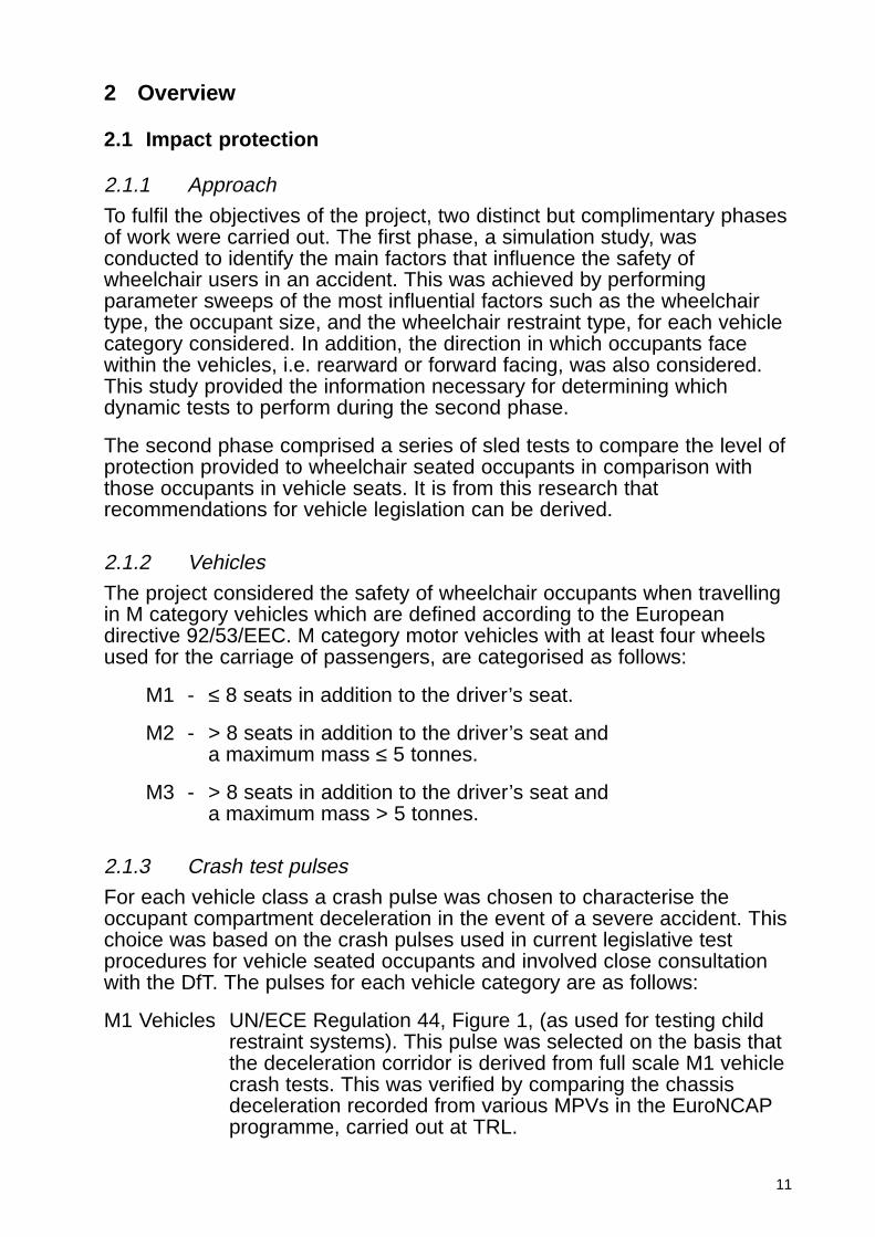
M1 Vehicles UN/ECE Regulation 44, Figure 1, (as used for testing childrestraint systems). This pulse was selected on the basis thatthe deceleration corridor is derived from full scale M1 vehiclecrash tests. This was verified by comparing the chassisdeceleration recorded from various MPVs in the EuroNCAPprogramme, carried out at TRL.
12
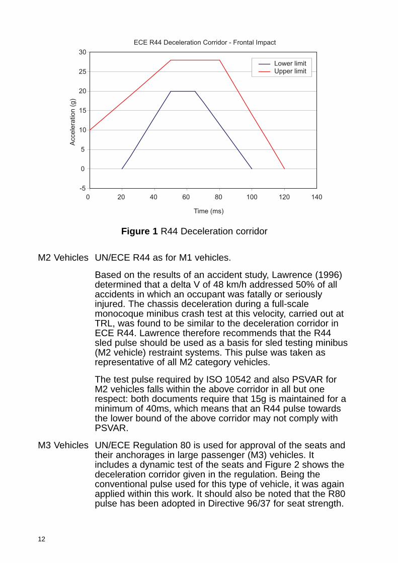
M2 Vehicles UN/ECE R44 as for M1 vehicles.
Based on the results of an accident study, Lawrence (1996)determined that a delta V of 48 km/h addressed 50% of allaccidents in which an occupant was fatally or seriouslyinjured. The chassis deceleration during a full-scalemonocoque minibus crash test at this velocity, carried out atTRL, was found to be similar to the deceleration corridor inECE R44. Lawrence therefore recommends that the R44sled pulse should be used as a basis for sled testing minibus(M2 vehicle) restraint systems. This pulse was taken asrepresentative of all M2 category vehicles.
The test pulse required by ISO 10542 and also PSVAR forM2 vehicles falls within the above corridor in all but onerespect: both documents require that 15g is maintained for aminimum of 40ms, which means that an R44 pulse towardsthe lower bound of the above corridor may not comply withPSVAR.
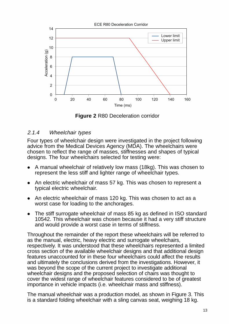
M3 Vehicles UN/ECE Regulation 80 is used for approval of the seats andtheir anchorages in large passenger (M3) vehicles. Itincludes a dynamic test of the seats and Figure 2 shows thedeceleration corridor given in the regulation. Being theconventional pulse used for this type of vehicle, it was againapplied within this work. It should also be noted that the R80pulse has been adopted in Directive 96/37 for seat strength.
ECE R44 Deceleration Corridor - Frontal Impact
-5
0
5
10
15
20
25
30
0 20 40 60 80 100 120 140
Time (ms)
Acce
lera
tio
n (
g)
Lower limitUpper limit
Figure 1 R44 Deceleration corridor
13
2.1.4 Wheelchair types
Four types of wheelchair design were investigated in the project followingadvice from the Medical Devices Agency (MDA). The wheelchairs werechosen to reflect the range of masses, stiffnesses and shapes of typicaldesigns. The four wheelchairs selected for testing were:
� A manual wheelchair of relatively low mass (18kg). This was chosen torepresent the less stiff and lighter range of wheelchair types.
� An electric wheelchair of mass 57 kg. This was chosen to represent atypical electric wheelchair.
� An electric wheelchair of mass 120 kg. This was chosen to act as aworst case for loading to the anchorages.
� The stiff surrogate wheelchair of mass 85 kg as defined in ISO standard10542. This wheelchair was chosen because it had a very stiff structureand would provide a worst case in terms of stiffness.
Throughout the remainder of the report these wheelchairs will be referred toas the manual, electric, heavy electric and surrogate wheelchairs,respectively. It was understood that these wheelchairs represented a limitedcross section of the available wheelchair designs and that additional designfeatures unaccounted for in these four wheelchairs could affect the resultsand ultimately the conclusions derived from the investigations. However, itwas beyond the scope of the current project to investigate additionalwheelchair designs and the proposed selection of chairs was thought tocover the widest range of wheelchair features considered to be of greatestimportance in vehicle impacts (i.e. wheelchair mass and stiffness).
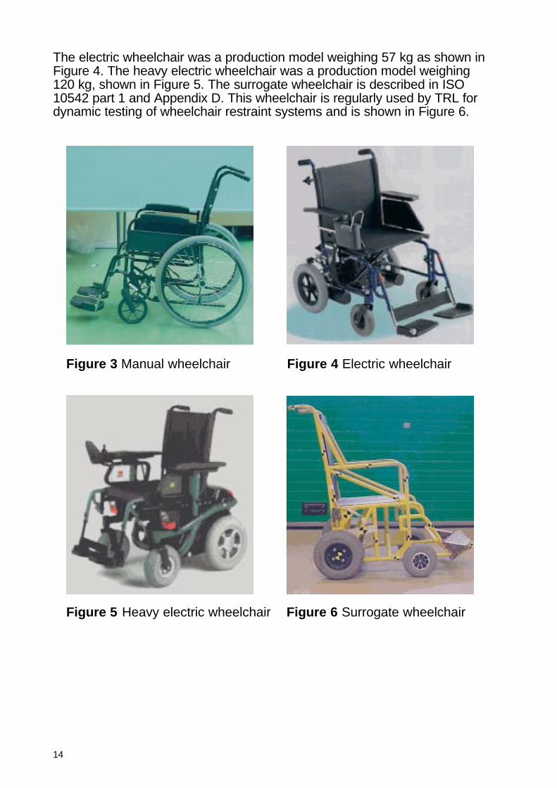
The manual wheelchair was a production model, as shown in Figure 3. Thisis a standard folding wheelchair with a sling canvas seat, weighing 18 kg.
ECE R80 Deceleration Corridor
0
2
4
6
8
10
12
14
0 20 40 60 80 100 120 140 160
Time (ms)
Accele
ration (
g)
Lower limitUpper limit
Figure 2 R80 Deceleration corridor
14
The electric wheelchair was a production model weighing 57 kg as shown inFigure 4. The heavy electric wheelchair was a production model weighing120 kg, shown in Figure 5. The surrogate wheelchair is described in ISO10542 part 1 and Appendix D. This wheelchair is regularly used by TRL fordynamic testing of wheelchair restraint systems and is shown in Figure 6.
Figure 3 Manual wheelchair Figure 4 Electric wheelchair
Figure 5 Heavy electric wheelchair Figure 6 Surrogate wheelchair
15
2.1.5 Anthropometric dummy selection
From the Hybrid III family of dummies, the 5th percentile female, the 50th
percentile male and the 95th percentile male were selected. Thesedummies were used to represent the wheelchair occupant for both themodelling and testing work. The reason for this choice was that the HybridIII family of dummies, and mainly the 50th percentile male, are used formost frontal impact legislative crash testing and hence can be regarded asthe current world standard for this type of testing.
It was originally proposed that the BIORID dummy would be used toassess occupant safety in all rear facing impacts as it is more biofidelicthan the Hybrid III dummy, having both a flexible spine and a biofidelicflexible neck. However, the BIORID dummy has been specifically designedand tested for impact speeds lower than 25 km/h, whereas the R44 andR80 pulses chosen for the investigations represent impact speeds of 50km/h and 30 km/h, respectively. Consequently, there were concerns thatthe BIORID dummy could be damaged if used in these tests and that therewould also be difficulties with the interpretation of test results given that thedummy has not been validated at these high impact speeds.
A suggested compromise was to use a Hybrid III dummy with a T-RIDneck. However, as with the BIORID dummy, this dummy configuration wasdesigned and validated at medium to low impact speeds. Discussions withthe neck developers at TNO established that although the T-RID neck ismore biofidelic than the Hybrid III dummy neck at low to medium severityimpacts, it would be expected that the response of a restrained T-RID neckwill match that of the Hybrid III neck at high impacts. Unrestrained, it isthought that the response of the Hybrid III neck would be more biofidelicthan the T-RID neck. As a result of these discussions it was decided that,although not ideal, the complete Hybrid III dummy would be used for therear facing impact investigations for both the modelling and the testingphases of the project. However, it must be remembered that the HYBRIDIIIdummy was developed for forward facing frontal impacts and as such itsbiofidelity for rear impacts cannot be taken for granted. Hence, any injurycriteria values measured for rear impact should be treated with caution asthey may not be representative of real injuries.
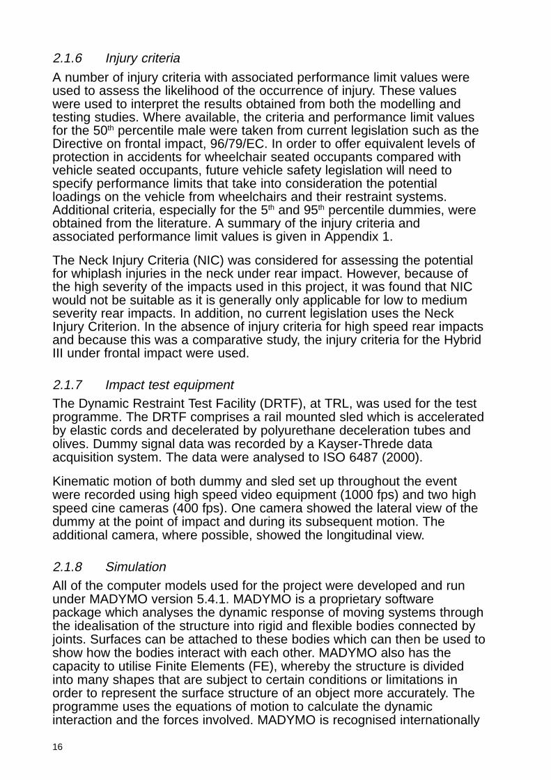
The tests were carried out using Hybrid III 5th, 50th and 95th percentiledummies. The dummies were fitted with triaxial accelerometers in thehead, chest and pelvis and fore/aftaccelerometers on the upper and lowerneck. The dummies also contained upperneck load cells and a chestpotentiometer, and the 50th percentile wasfitted with a lumbar spine load cell. Intests where the dummy was restrained byan occupant restraint the belt loads werealso recorded. The masses of thedummies are given in Table 1.
Table 1 Hybrid III dummy masses
Dummy Mass (kg)
5th 5050th 7595th 100
16
2.1.6 Injury criteria
A number of injury criteria with associated performance limit values wereused to assess the likelihood of the occurrence of injury. These valueswere used to interpret the results obtained from both the modelling andtesting studies. Where available, the criteria and performance limit valuesfor the 50th percentile male were taken from current legislation such as theDirective on frontal impact, 96/79/EC. In order to offer equivalent levels ofprotection in accidents for wheelchair seated occupants compared withvehicle seated occupants, future vehicle safety legislation will need tospecify performance limits that take into consideration the potentialloadings on the vehicle from wheelchairs and their restraint systems.Additional criteria, especially for the 5th and 95th percentile dummies, wereobtained from the literature. A summary of the injury criteria andassociated performance limit values is given in Appendix 1.
The Neck Injury Criteria (NIC) was considered for assessing the potentialfor whiplash injuries in the neck under rear impact. However, because ofthe high severity of the impacts used in this project, it was found that NICwould not be suitable as it is generally only applicable for low to mediumseverity rear impacts. In addition, no current legislation uses the NeckInjury Criterion. In the absence of injury criteria for high speed rear impactsand because this was a comparative study, the injury criteria for the HybridIII under frontal impact were used.
2.1.7 Impact test equipmentThe Dynamic Restraint Test Facility (DRTF), at TRL, was used for the testprogramme. The DRTF comprises a rail mounted sled which is acceleratedby elastic cords and decelerated by polyurethane deceleration tubes andolives. Dummy signal data was recorded by a Kayser-Threde dataacquisition system. The data were analysed to ISO 6487 (2000).
Kinematic motion of both dummy and sled set up throughout the eventwere recorded using high speed video equipment (1000 fps) and two highspeed cine cameras (400 fps). One camera showed the lateral view of thedummy at the point of impact and during its subsequent motion. Theadditional camera, where possible, showed the longitudinal view.
2.1.8 SimulationAll of the computer models used for the project were developed and rununder MADYMO version 5.4.1. MADYMO is a proprietary softwarepackage which analyses the dynamic response of moving systems throughthe idealisation of the structure into rigid and flexible bodies connected byjoints. Surfaces can be attached to these bodies which can then be used toshow how the bodies interact with each other. MADYMO also has thecapacity to utilise Finite Elements (FE), whereby the structure is dividedinto many shapes that are subject to certain conditions or limitations inorder to represent the surface structure of an object more accurately. Theprogramme uses the equations of motion to calculate the dynamicinteraction and the forces involved. MADYMO is recognised internationally
17
as ‘state of the art’ and is widely used in the automotive industry for thesimulation of occupant kinematics.
For all the models, contact stiffnesses were defined between:
� The wheelchair and the ground.
� The dummy and the wheelchair.
� Wherever contact occurred between:
– the vehicle interior and the dummy;
– the vehicle interior and the wheelchair.
Where experimental data was lacking, the contact stiffnesses were eitherestimated or derived from other MADYMO models.
2.2 Non impact protection
2.2.1 BackgroundTRL has previously conducted a field study of longitudinal and lateralaccelerations on buses. Accelerations were measured on a range ofvehicles over routes known to be particularly difficult to negotiate. Lateralaccelerations over 0.2g were recorded on all the journeys in the study andin 18% of cases, accelerations over 0.35g were measured. In a fewinstances the acceleration exceeded 0.4g.
In general, the larger buses sustained fewer lateral accelerations over0.35g, and low floor buses were marginally better than conventional buses.
2.2.2 ApproachA study was undertaken as part of this project to determine the extent ofwheelchair movement on board a large bus (M3) under normal drivingconditions, i.e. non-impact conditions.
2.2.3 VehicleAn 11.5 m long Optare Excel, which is compliant with the Public ServiceVehicles Accessibility Regulations 2000, was used for these tests. Theregulations allow the wheelchair user to travel unrestrained in a rear facingposition against a head and back restraint.
2.2.4 Driving conditionsThe vehicle was driven in a semicircle with a radius of 20 metres, at avelocity of 38 – 40 kilometres per hour.
2.2.5 Wheelchair typesThe wheelchair used for these experiments was the PSVAR referencechair.
18
3 M1 and M2 forward facing
3.1 Simulation study
Twenty-eight analyses of the numerical model were carried out asdescribed in Appendix 2. Various combinations of wheelchair, dummy sizeand restraint system were examined along with an investigation into theinfluence of the deceleration level within the ECE R44 corridor.
The results suggested that a floor anchored occupant restraint might beless favourable, compared with an upper anchorage location. This wasbased on both the dummy kinematics and the predicted occupant loadingduring the impact. When using the floor mounted restraint, the upper bodyrotated forwards about the waist, resulting in a high head excursion and insome cases head contact with the legs. In general, the dummy forces andaccelerations were higher also, and there were more instances where theinjury limits were exceeded.
There was not a significant difference in the dummy load levels betweendifferent wheelchairs. The method of wheelchair restraint was also found tohave little effect, although greater wheelchair excursion was predictedwhen clamps were used.
The simulations predicted that dummy excursion and loading were linkedto occupant size. In general, analyses with the Hybrid III 95th percentilepredicted the highest values of these parameters, but the injury limits forthis dummy were also greater and so the higher readings did notnecessarily indicate greater injury risk.
Finally, equivalent models were subjected to two different decelerationpulses, both within the ECE R44 corridor. The results indicated thatalthough the R44 corridor allows for acceleration variations of up to 8g,differences of only 5g in the peak deceleration level could noticeably affectthe predicted dummy loads. This finding should be borne in mind wheninterpreting the predictions.
3.2 Scope of testing
To further investigate forward facing occupants in M1 and M2 categoryvehicles a series of dynamic tests were carried out. The findings from thesimulation work were considered when planning the test programme.
The primary objective for the test series was to assess whether thewheelchair seated occupant was provided with an equivalent level of safetyas the vehicle seated occupant, through the use of instrumented dummiesto compare the loading on the occupant.
In addition to this, the effect of diagonal belt anchor location wasexamined. The simulation work suggested that use of a floor anchoredoccupant restraint could have a negative effect on occupant protectionwhen compared with an upper anchorage location. It was thereforenecessary to revisit this issue in the test series.
19
The effects of a head and back restraint were also investigated todetermine whether this could improve the protection for the occupant withrespect to neck extension and movement in rebound.
The occupant space required within the vehicle was also assessed alongwith the loads that the vehicle anchorages would be required to withstand,in order to set requirements for vehicles.
3.3 Test design
In order to investigate M1 and M2 vehicle requirements eight sled testswith various set ups were carried out.
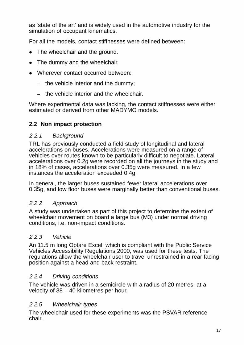
3.3.1 Occupant loading
Six of the eight tests investigated occupant loading. A vehicle seatedbaseline test was completed for comparative purposes using a Hybrid III50th percentile dummy in a commercially available seat that incorporated athree-point occupant restraint and head restraint integrated into the seat.This is shown in Figure 7. Figure 8 shows a typical set up for thewheelchair seated occupant.
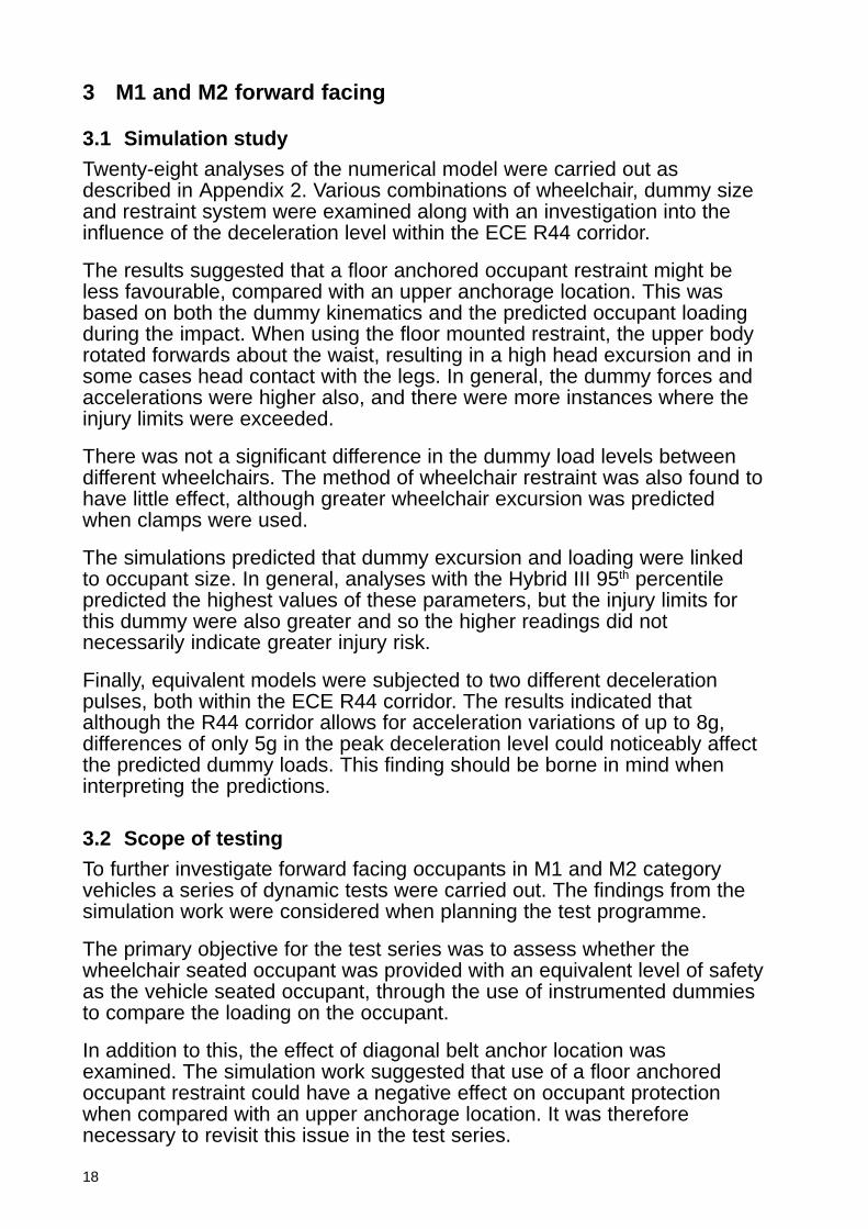
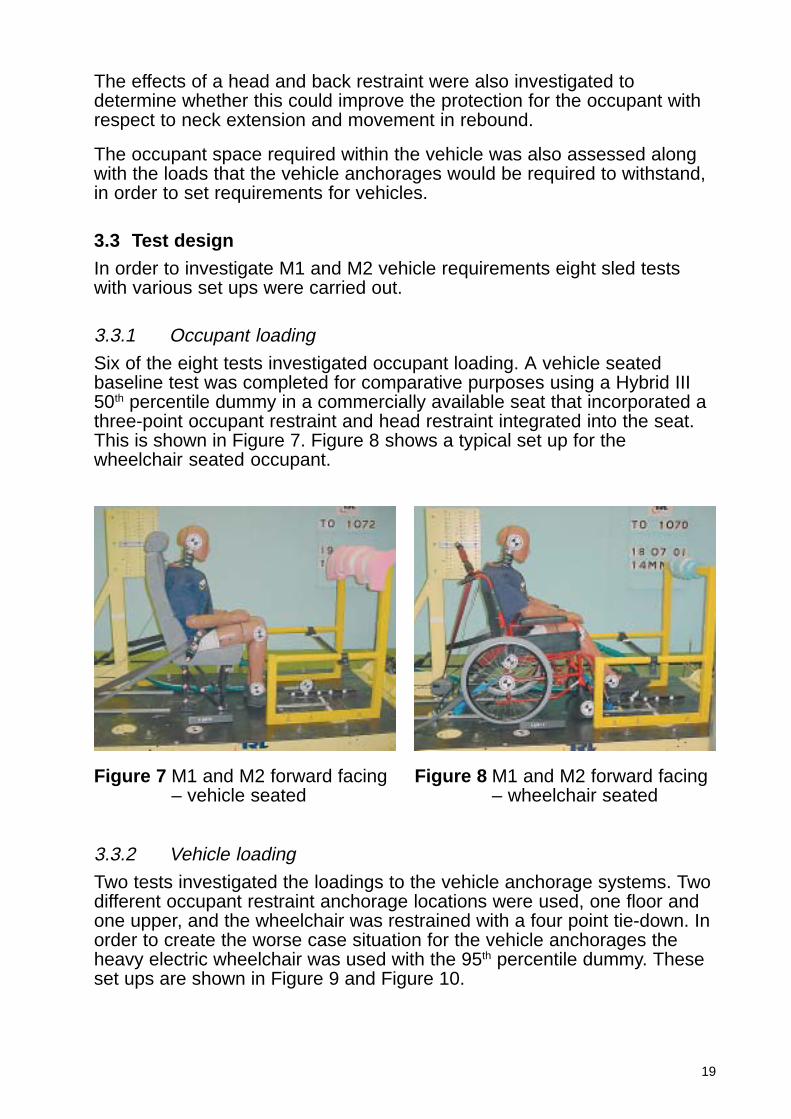
3.3.2 Vehicle loading
Two tests investigated the loadings to the vehicle anchorage systems. Twodifferent occupant restraint anchorage locations were used, one floor andone upper, and the wheelchair was restrained with a four point tie-down. Inorder to create the worse case situation for the vehicle anchorages theheavy electric wheelchair was used with the 95th percentile dummy. Theseset ups are shown in Figure 9 and Figure 10.
Figure 7 M1 and M2 forward facing– vehicle seated
Figure 8 M1 and M2 forward facing– wheelchair seated
20
3.3.3 Sled configuration
The vehicle environment for a minibus and taxi was represented on thesled. A production model minibus seat was used for the vehicle seatedoccupant test which incorporated an integrated 3-point restraint system.
The wheelchairs were restrained by a four point webbing tie-down securedto the floor by purpose designed Aluminium Track Fittings (ATF). Thedummy was restrained independently by a lap and diagonal inertia restraintin all tests. Two types of wheelchair occupant restraint were investigated tocompare the effects of different shoulder belt anchor locations. These wereanchored to either an upper location or the floor.
The test set up for measurement of the restraint anchorage loadingrequired additional instrumentation adjacent to all anchor locations in orderto record the forces generated during the impact. Markers were positionedto enable measurement of the restraint angles at peak loading.
All wheelchair tie-down and occupant restraints were installed according tothe manufacturer’s instructions and the ISO standards.
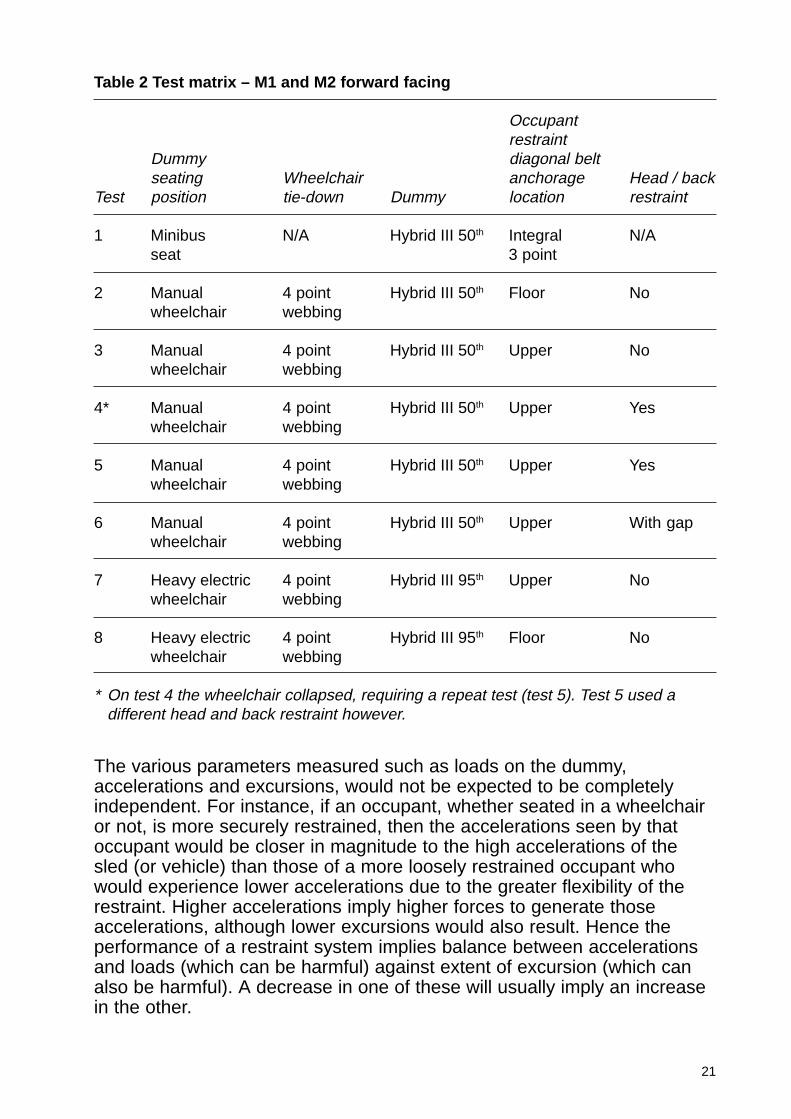
Table 2 details the various test configurations used for the forward facingM1 and M2 vehicle research.
3.4 Findings
3.4.1 Relative safety of current situation (Tests 1, 2 and 3)
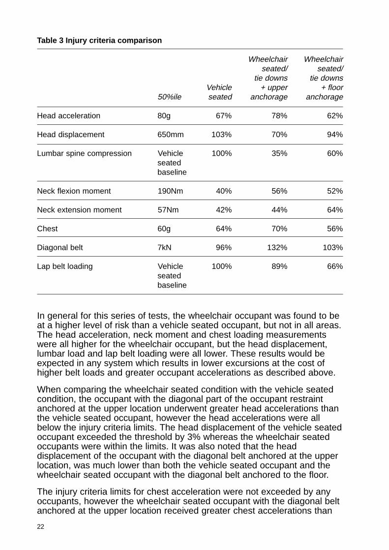
In order to compare the safety of the wheelchair seated occupants with thesafety of the vehicle seated occupants the occupant loadings have beenexpressed as a percentage of the injury threshold values. Where there areno injury criteria limits the vehicle seated results have been used as a baseline (i.e. 100%), these results are shown in Table 3.
Figure 9 Set up with upperanchorage location fordiagonal occupantrestraint
Figure 10 Set up with flooranchorage location fordiagonal occupantrestraint
21
The various parameters measured such as loads on the dummy,accelerations and excursions, would not be expected to be completelyindependent. For instance, if an occupant, whether seated in a wheelchairor not, is more securely restrained, then the accelerations seen by thatoccupant would be closer in magnitude to the high accelerations of thesled (or vehicle) than those of a more loosely restrained occupant whowould experience lower accelerations due to the greater flexibility of therestraint. Higher accelerations imply higher forces to generate thoseaccelerations, although lower excursions would also result. Hence theperformance of a restraint system implies balance between accelerationsand loads (which can be harmful) against extent of excursion (which canalso be harmful). A decrease in one of these will usually imply an increasein the other.
Table 2 Test matrix – M1 and M2 forward facing
Occupantrestraint
Dummy diagonal beltseating Wheelchair anchorage Head / back
Test position tie-down Dummy location restraint
1 Minibus N/A Hybrid III 50th Integral N/Aseat 3 point
2 Manual 4 point Hybrid III 50th Floor Nowheelchair webbing
3 Manual 4 point Hybrid III 50th Upper Nowheelchair webbing
4* Manual 4 point Hybrid III 50th Upper Yeswheelchair webbing
5 Manual 4 point Hybrid III 50th Upper Yeswheelchair webbing
6 Manual 4 point Hybrid III 50th Upper With gapwheelchair webbing
7 Heavy electric 4 point Hybrid III 95th Upper Nowheelchair webbing
8 Heavy electric 4 point Hybrid III 95th Floor Nowheelchair webbing
* On test 4 the wheelchair collapsed, requiring a repeat test (test 5). Test 5 used adifferent head and back restraint however.
22
In general for this series of tests, the wheelchair occupant was found to beat a higher level of risk than a vehicle seated occupant, but not in all areas.The head acceleration, neck moment and chest loading measurementswere all higher for the wheelchair occupant, but the head displacement,lumbar load and lap belt loading were all lower. These results would beexpected in any system which results in lower excursions at the cost ofhigher belt loads and greater occupant accelerations as described above.
When comparing the wheelchair seated condition with the vehicle seatedcondition, the occupant with the diagonal part of the occupant restraintanchored at the upper location underwent greater head accelerations thanthe vehicle seated occupant, however the head accelerations were allbelow the injury criteria limits. The head displacement of the vehicle seatedoccupant exceeded the threshold by 3% whereas the wheelchair seatedoccupants were within the limits. It was also noted that the headdisplacement of the occupant with the diagonal belt anchored at the upperlocation, was much lower than both the vehicle seated occupant and thewheelchair seated occupant with the diagonal belt anchored to the floor.
The injury criteria limits for chest acceleration were not exceeded by anyoccupants, however the wheelchair seated occupant with the diagonal beltanchored at the upper location received greater chest accelerations than
Table 3 Injury criteria comparison
Wheelchair Wheelchairseated/ seated/
tie downs tie downsVehicle + upper + floor
50%ile seated anchorage anchorage
Head acceleration 80g 67% 78% 62%
Head displacement 650mm 103% 70% 94%
Lumbar spine compression Vehicle 100% 35% 60%seatedbaseline
Neck flexion moment 190Nm 40% 56% 52%
Neck extension moment 57Nm 42% 44% 64%
Chest 60g 64% 70% 56%
Diagonal belt 7kN 96% 132% 103%
Lap belt loading Vehicle 100% 89% 66%seatedbaseline

23
the vehicle seated occupant. This would be expected as the vehicle seatedoccupant exceeded the head displacement limit and the wheelchair seatedoccupant was restrained more securely in this case with lower headdisplacements. The greater security of restraint was due to theconventional seat’s upper anchorage being fixed to the seat itself. Thisallowed the seat to deflect and allow greater flexibility in the restraintsystem. The occupant restraint, however, is attached to the floor via aguide at the upper location which is a more secure system. Occupantprotection is a compromise between the displacement of the body parts(where contact can be made with the vehicle interior) and accelerationscaused by restraining the body. This effect is also seen in the loading ofthe diagonal belt where the wheelchair seated occupants exceeded theinjury criteria limit but also had reduced head displacements.
The vehicle seated and wheelchair seated occupants were all within theinjury criteria for neck extension, however the injury risk for wheelchairseated occupants was greater than for the vehicle seated occupants.
3.4.2 Effect of restraint geometry (Tests 2 and 3)
When the diagonal section of the occupant restraint was anchored directlyto the floor, the dummy was subjected to a downward force that resulted inhigh loads on the wheelchair, reducing its structural performance. Whenthe test was conducted with the diagonal belt passing through an upperanchorage location this downward force was minimal and the wheelchairdid not deform to the same extent.
The upper anchorage location provided better restraint for the torso of thedummy, reducing the head excursion compared with the floor anchoredsystem, where the upper body rotated about the waist. However, becauseoccupant protection is a compromise between displacement and loadings,the head acceleration, chest acceleration and diagonal belt loadings wereall greater in the case of the upper anchorage although only the loading tothe diagonal belt exceeded the criteria threshold. This outcome indicatesthat an occupant restraint that is anchored to the upper location is morelikely to provide a balanced level of protection between loadings andexcursion. It should be considered, however, that in general excursion willbe of less concern for a wheelchair seated occupant than a conventionallyseated occupant as vehicle interior structure is not usually placed withinthe excursion zone.
The other important observation that arose when comparing these twooccupant restraint systems related to the loadings on the neck and spine.The floor anchored diagonal restraint system generated greatercompressive loads on the lumbar spine, and created greater flexion andextension on the neck. A compressive load of 1.58 kN was recorded in thelumbar spine during the floor mounted test and the corresponding figure forthe upper anchorage test was 0.92 kN. However, as no injury criteria existfor the Hybrid III lumbar spine, it is not possible to determine whether thiswould lead to lumbar spine compression fractures.
24
The results from this comparison show that an occupant restrained with anupper anchorage mounted diagonal belt is better controlled in terms ofinjury prevention, than an occupant in a restraint system where thediagonal shoulder strap is anchored to the floor.
3.4.3 Effect of occupant size
This was not examined for M1 and M2 forward facing.
3.4.4 Effect of wheelchair stiffness
This was not examined for M1 and M2 forward facing.
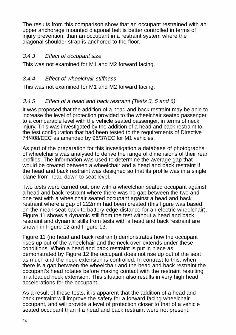
3.4.5 Effect of a head and back restraint (Tests 3, 5 and 6)
It was proposed that the addition of a head and back restraint may be able toincrease the level of protection provided to the wheelchair seated passengerto a comparable level with the vehicle seated passenger, in terms of neckinjury. This was investigated by the addition of a head and back restraint tothe test configuration that had been tested to the requirements of Directive74/408/EEC as amended by 96/37/EC for M1 vehicles.
As part of the preparation for this investigation a database of photographsof wheelchairs was analysed to derive the range of dimensions of their rearprofiles. The information was used to determine the average gap thatwould be created between a wheelchair and a head and back restraint ifthe head and back restraint was designed so that its profile was in a singleplane from head down to seat level.
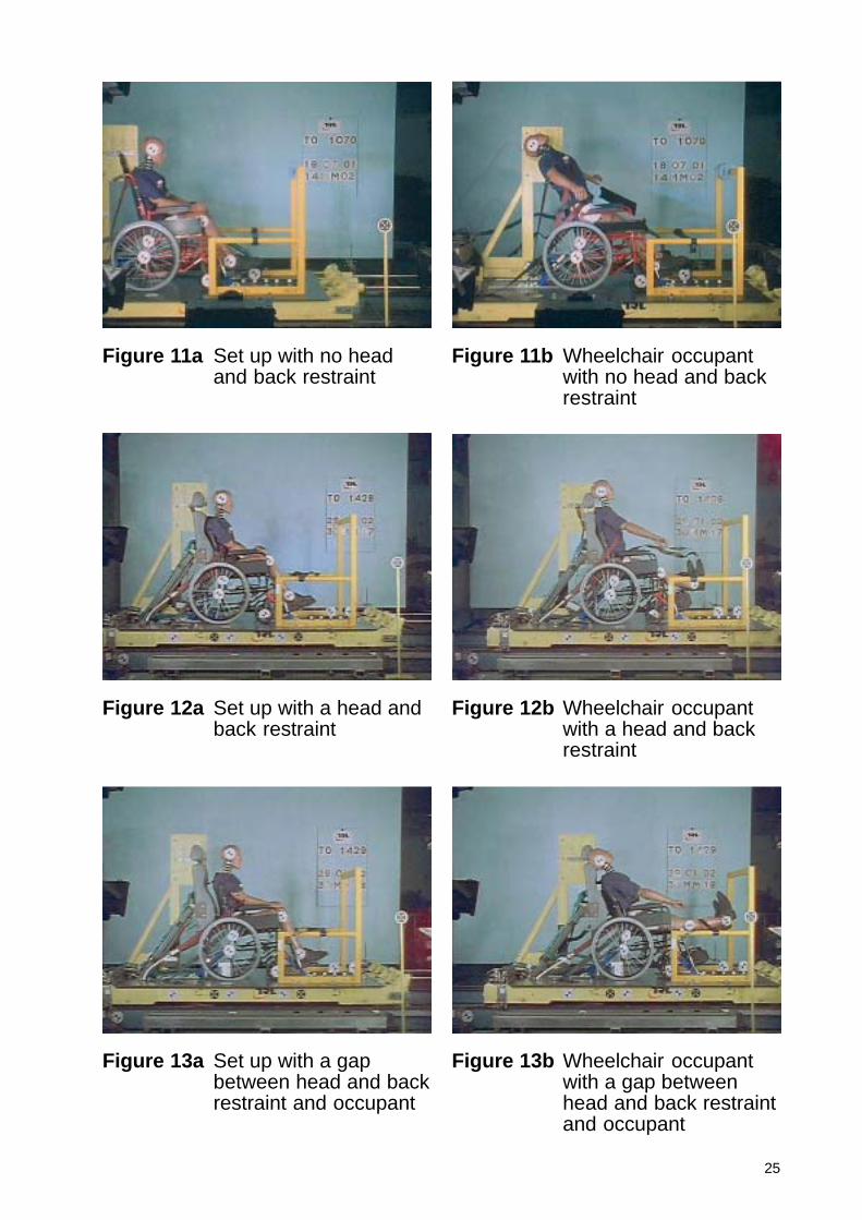
Two tests were carried out, one with a wheelchair seated occupant againsta head and back restraint where there was no gap between the two andone test with a wheelchair seated occupant against a head and backrestraint where a gap of 222mm had been created (this figure was basedon the mean seat-back to battery edge distance for an electric wheelchair).Figure 11 shows a dynamic still from the test without a head and backrestraint and dynamic stills from tests with a head and back restraint areshown in Figure 12 and Figure 13.
Figure 11 (no head and back restraint) demonstrates how the occupantrises up out of the wheelchair and the neck over extends under theseconditions. When a head and back restraint is put in place asdemonstrated by Figure 12 the occupant does not rise up out of the seatas much and the neck extension is controlled. In contrast to this, whenthere is a gap between the wheelchair and the head and back restraint theoccupant’s head rotates before making contact with the restraint resultingin a loaded neck extension. This situation also results in very high headaccelerations for the occupant.
As a result of these tests, it is apparent that the addition of a head andback restraint will improve the safety for a forward facing wheelchairoccupant, and will provide a level of protection closer to that of a vehicleseated occupant than if a head and back restraint were not present.
25
Figure 12a Set up with a head andback restraint
Figure 12b Wheelchair occupantwith a head and backrestraint
Figure 13a Set up with a gapbetween head and backrestraint and occupant
Figure 13b Wheelchair occupantwith a gap betweenhead and back restraintand occupant
Figure 11a Set up with no headand back restraint
Figure 11b Wheelchair occupantwith no head and backrestraint
26
However, even without a head and back restraint all injury criteria arebelow the conventional threshold values, although it should be consideredthat wheelchair users may have a lower tolerance to injury than indicatedby the conventional threshold values.
It is necessary to ensure that there is no gap between the wheelchair andthe head and back restraint to gain maximum benefit. The same conclusionwould apply to a vehicle seated occupant and their head restraint.
3.4.6 Head and back restraint strength
This was not examined for M1 and M2 forward facing.
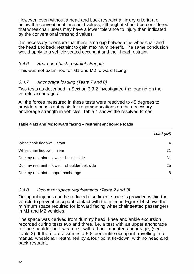
3.4.7 Anchorage loading (Tests 7 and 8)
Two tests as described in Section 3.3.2 investigated the loading on thevehicle anchorages.
All the forces measured in these tests were resolved to 45 degrees toprovide a consistent basis for recommendations on the necessaryanchorage strength in vehicles. Table 4 shows the resolved forces.
Table 4 M1 and M2 forward facing – restraint anchorage loads
Load (kN)
Wheelchair tiedown – front 4
Wheelchair tiedown – rear 31
Dummy restraint – lower – buckle side 31
Dummy restraint – lower – shoulder belt side 25
Dummy restraint – upper anchorage 8
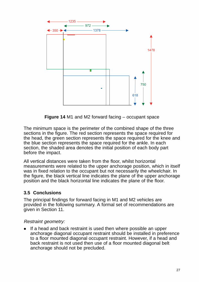
3.4.8 Occupant space requirements (Tests 2 and 3)
Occupant injuries can be reduced if sufficient space is provided within thevehicle to prevent occupant contact with the interior. Figure 14 shows theminimum space required for forward facing wheelchair seated passengersin M1 and M2 vehicles.
The space was derived from dummy head, knee and ankle excursionrecorded during tests two and three, i.e. a test with an upper anchoragefor the shoulder belt and a test with a floor mounted anchorage, (seeTable 2). It therefore assumes a 50th percentile occupant travelling in amanual wheelchair restrained by a four point tie-down, with no head andback restraint.
27
The minimum space is the perimeter of the combined shape of the threesections in the figure. The red section represents the space required forthe head, the green section represents the space required for the knee andthe blue section represents the space required for the ankle. In eachsection, the shaded area denotes the initial position of each body partbefore the impact.
All vertical distances were taken from the floor, whilst horizontalmeasurements were related to the upper anchorage position, which in itselfwas in fixed relation to the occupant but not necessarily the wheelchair. Inthe figure, the black vertical line indicates the plane of the upper anchorageposition and the black horizontal line indicates the plane of the floor.
3.5 Conclusions
The principal findings for forward facing in M1 and M2 vehicles areprovided in the following summary. A formal set of recommendations aregiven in Section 11.
Restraint geometry:
� If a head and back restraint is used then where possible an upperanchorage diagonal occupant restraint should be installed in preferenceto a floor mounted diagonal occupant restraint. However, if a head andback restraint is not used then use of a floor mounted diagonal beltanchorage should not be precluded.
1235
972
1378350
1478
750
618
Figure 14 M1 and M2 forward facing – occupant space
28
Head and back restraint:
� Use of a head and back restraint is recommended as it provides a levelof protection closer to that of an occupant seated in a vehicle seat witha head restraint, but it is not absolutely necessary to prevent injury.However, the project did not examine any increased susceptibility ofwheelchair users to injury, and hence it is a matter of risk assessment,taking into account the cost of fitting such devices, as to whether ahead and back restraint should be fitted for forward facing wheelchairusers.
The occupant should be positioned so that their torso is against thehead and back restraint. The head and back restraint should be testedto the requirements of Directive 74/408/EEC as amended by 96/37/ECfor M1 vehicles.
� Wheelchair and vehicle manufacturers should be aware of thedetrimental effect of a gap between the wheelchair and head and backrestraint, and should work with all involved to minimise this gap. Thisrequires an understanding of the issues, and effective communicationbetween the wheelchair tie-down and occupant restraint manufacturerand the vehicle manufacturer.
Vehicle anchorages:
� When a wheelchair has a four point tie-down system each of the frontanchorages should be able to withstand a loading of 5kN in a rearwardand upward direction at an angle of 45 degrees to the horizontal. Eachof the rear anchorages should be able to withstand a load of 30kNapplied in a forward and upward direction at an angle of 45 degrees tothe horizontal.
� The anchorages of an occupant restraint system should be able towithstand 10kN at the upper anchorage applied forward and downwardat a 45 degree angle to the horizontal and 30kN at each of the flooranchorages applied in a forward and upward direction at an angle of 45degrees to the horizontal.
Occupant space:
� Based on an enclosing area summarising the measurements given inFigure 14, any wheelchair space should comply with the followingrequirements.
A wheelchair space shall not be less than:
� 1300mm measured in the longitudinal plane of the vehicle up to aheight of 1500mm;
� 1750mm measured in the longitudinal plane of the vehicle up to aheight of 750mm (for prevention of contact between the lowerextremities and the vehicle interior).
29
4 M1 and M2 rear facing
4.1 Simulation studyTwelve analyses of the numerical model were carried out for this conditionas described in detail in Appendix 2. The model included a representationof a typical vehicle environment around the wheelchair based on a purposebuilt taxi. The wheelchair was positioned rear facing against the bulkheadseparating the driver and passenger compartments.
Manual, electric and surrogate wheelchair models were compared as partof the study and additional analyses were carried out with a head and backrestraint to determine whether this would reduce occupant loading.
The results suggested that a head and back restraint would be needed ifthe injury criteria limits were not to be exceeded as there was excessiverearwards head movement and over extension of the neck predicted bymost of the analyses. The recommendations for the testing programmewere to compare the protection afforded to the wheelchair occupant withand without a head and back restraint, with consideration being given tothe energy absorption characteristics of the head and back restraint.
4.2 ScopeTo further investigate rear facing occupants in M1 and M2 vehicles a seriesof dynamic tests were carried out. The findings from the simulation workwere considered when planning the test programme.
The primary objective in the test series was to assess whether thewheelchair seated occupant was provided with the same level of safety asthe vehicle seated occupant, through the use of instrumented dummies tocompare the occupant loading.
In addition, the effects of occupant size and wheelchair stiffness wereinvestigated. The use of a head and back restraint was also examined, tosee whether its use could improve the protection provided for the occupantwith respect to neck extension and movement.
Finally, a test was carried out to determine the dynamic strengthrequirements for a head and back restraint for rear facing wheelchair usersin M1 and M2 vehicles.
4.3 Test configurationIn order to investigate rear facing M1 and M2 vehicle requirements, ten sledtests with various configurations were carried out (see test matrix, Table 5).
30
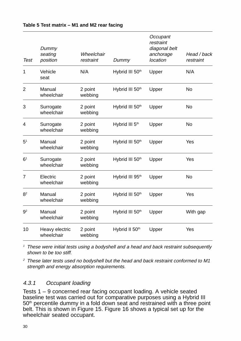
4.3.1 Occupant loading
Tests 1 – 9 concerned rear facing occupant loading. A vehicle seatedbaseline test was carried out for comparative purposes using a Hybrid III50th percentile dummy in a fold down seat and restrained with a three pointbelt. This is shown in Figure 15. Figure 16 shows a typical set up for thewheelchair seated occupant.
Table 5 Test matrix – M1 and M2 rear facing
Occupantrestraint
Dummy diagonal beltseating Wheelchair anchorage Head / back
Test position restraint Dummy location restraint
1 Vehicle N/A Hybrid III 50th Upper N/Aseat
2 Manual 2 point Hybrid III 50th Upper Nowheelchair webbing
3 Surrogate 2 point Hybrid III 50th Upper Nowheelchair webbing
4 Surrogate 2 point Hybrid III 5th Upper Nowheelchair webbing
51 Manual 2 point Hybrid III 50th Upper Yeswheelchair webbing
61 Surrogate 2 point Hybrid III 50th Upper Yeswheelchair webbing
7 Electric 2 point Hybrid III 95th Upper Nowheelchair webbing
82 Manual 2 point Hybrid III 50th Upper Yeswheelchair webbing
92 Manual 2 point Hybrid III 50th Upper With gapwheelchair webbing
10 Heavy electric 2 point Hybrid II 50th Upper Yeswheelchair webbing
1 These were initial tests using a bodyshell and a head and back restraint subsequentlyshown to be too stiff.
2 These later tests used no bodyshell but the head and back restraint conformed to M1strength and energy absorption requirements.
31
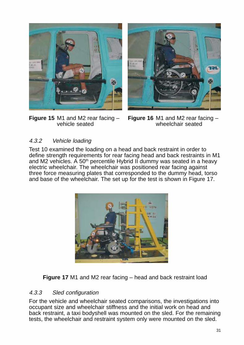
4.3.2 Vehicle loading
Test 10 examined the loading on a head and back restraint in order todefine strength requirements for rear facing head and back restraints in M1and M2 vehicles. A 50th percentile Hybrid II dummy was seated in a heavyelectric wheelchair. The wheelchair was positioned rear facing againstthree force measuring plates that corresponded to the dummy head, torsoand base of the wheelchair. The set up for the test is shown in Figure 17.
Figure 15 M1 and M2 rear facing –vehicle seated
Figure 16 M1 and M2 rear facing –wheelchair seated
Figure 17 M1 and M2 rear facing – head and back restraint load
4.3.3 Sled configuration
For the vehicle and wheelchair seated comparisons, the investigations intooccupant size and wheelchair stiffness and the initial work on head andback restraint, a taxi bodyshell was mounted on the sled. For the remainingtests, the wheelchair and restraint system only were mounted on the sled.
32
The wheelchairs were restrained by a 2 point webbing tie-down system. Thisconsisted of a Y-shaped heavy duty webbing strap that attached to the rearof the wheelchair by means of two large hooks. The dummy was restrainedindependently with a three point lap and diagonal inertia restraint.
4.4 Findings
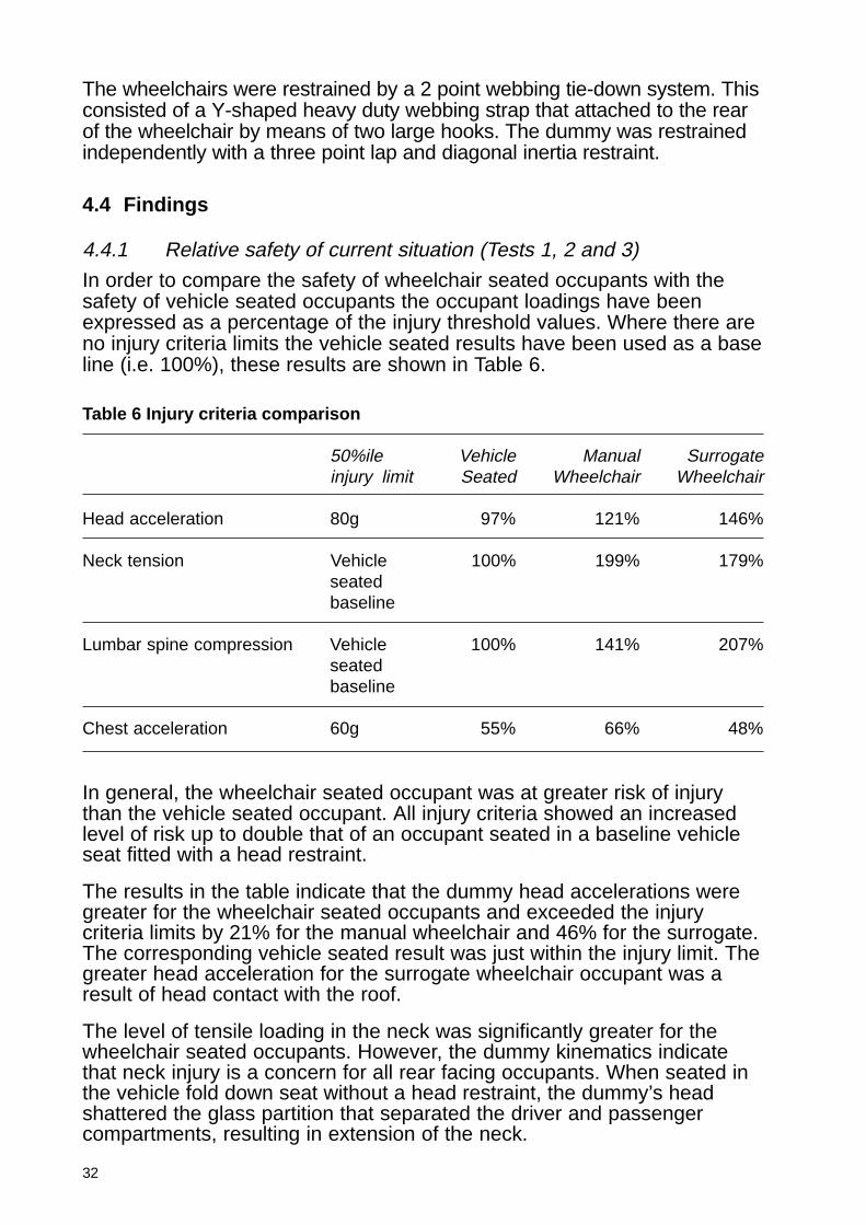
4.4.1 Relative safety of current situation (Tests 1, 2 and 3)
In order to compare the safety of wheelchair seated occupants with thesafety of vehicle seated occupants the occupant loadings have beenexpressed as a percentage of the injury threshold values. Where there areno injury criteria limits the vehicle seated results have been used as a baseline (i.e. 100%), these results are shown in Table 6.
Table 6 Injury criteria comparison
50%ile Vehicle Manual Surrogateinjury limit Seated Wheelchair Wheelchair
Head acceleration 80g 97% 121% 146%
Neck tension Vehicle 100% 199% 179%seatedbaseline
Lumbar spine compression Vehicle 100% 141% 207%seatedbaseline
Chest acceleration 60g 55% 66% 48%
In general, the wheelchair seated occupant was at greater risk of injurythan the vehicle seated occupant. All injury criteria showed an increasedlevel of risk up to double that of an occupant seated in a baseline vehicleseat fitted with a head restraint.
The results in the table indicate that the dummy head accelerations weregreater for the wheelchair seated occupants and exceeded the injurycriteria limits by 21% for the manual wheelchair and 46% for the surrogate.The corresponding vehicle seated result was just within the injury limit. Thegreater head acceleration for the surrogate wheelchair occupant was aresult of head contact with the roof.
The level of tensile loading in the neck was significantly greater for thewheelchair seated occupants. However, the dummy kinematics indicatethat neck injury is a concern for all rear facing occupants. When seated inthe vehicle fold down seat without a head restraint, the dummy’s headshattered the glass partition that separated the driver and passengercompartments, resulting in extension of the neck.
33
The injury criterion for chest acceleration was not exceeded. However themanual wheelchair seated occupant received greater chest accelerationsthan the vehicle seated occupant. This was due to the dummy loading thebulkhead after the stitching in the canvas seat back of the manualwheelchair partially failed.
The level of lumbar spine compression was greatest for the wheelchairseated occupants. However no injury criteria exist for the Hybrid III lumbarspine, so it is not possible to determine whether this would lead to lumbarspine injury.
The comparison of rear facing vehicle and wheelchair seated occupantsindicates that head acceleration and neck loading are the primary areas ofconcern for the wheelchair seated occupants.
4.4.2 Effect of restraint geometry
This was not examined for M1 and M2 rear facing.
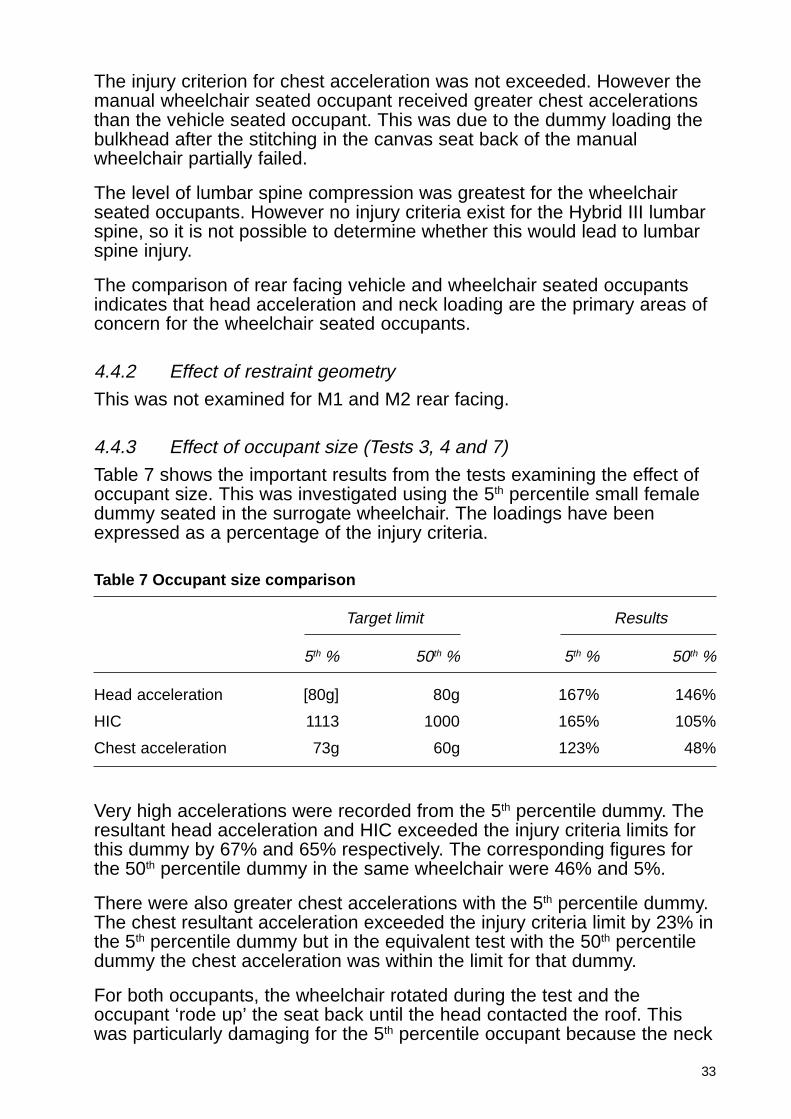
4.4.3 Effect of occupant size (Tests 3, 4 and 7)
Table 7 shows the important results from the tests examining the effect ofoccupant size. This was investigated using the 5th percentile small femaledummy seated in the surrogate wheelchair. The loadings have beenexpressed as a percentage of the injury criteria.
Table 7 Occupant size comparison
Target limit Results
5th % 50th % 5th % 50th %
Head acceleration [80g] 80g 167% 146%
HIC 1113 1000 165% 105%
Chest acceleration 73g 60g 123% 48%
Very high accelerations were recorded from the 5th percentile dummy. Theresultant head acceleration and HIC exceeded the injury criteria limits forthis dummy by 67% and 65% respectively. The corresponding figures forthe 50th percentile dummy in the same wheelchair were 46% and 5%.
There were also greater chest accelerations with the 5th percentile dummy.The chest resultant acceleration exceeded the injury criteria limit by 23% inthe 5th percentile dummy but in the equivalent test with the 50th percentiledummy the chest acceleration was within the limit for that dummy.
For both occupants, the wheelchair rotated during the test and theoccupant ‘rode up’ the seat back until the head contacted the roof. Thiswas particularly damaging for the 5th percentile occupant because the neck

34
had fully extended when head contact occurred resulting in a loaded neckextension as the torso continued to rise.
An additional test was carried out with the 95th percentile, large maledummy seated in an electric wheelchair. As a different wheelchair wasused in this test, it cannot be used for direct comparison with the tests with5th and 50th percentile dummies. However it can be used to give anindication of the outcome for an occupant of this size seated in a taxi.
High accelerations were recorded in this test, most noticeably in the chest.The high chest accelerations were probably due to loading from ahorizontal bar in the seatback structure of the electric wheelchair. Thechest resultant acceleration exceeded the limit for this dummy by 182%.The resultant head acceleration exceeded the injury criteria limit by 44%.
Due to the size of the dummy there was not as much room in the taxi forthe neck to extend. Consequently, the head made contact with the rigidsection at the top of the bulkhead. At the same time the torso wasstretched around the bulkhead causing the front of the lumbar spine to failin tension. When compared with a human, the Hybrid III lumbar spine isrelatively stiff to provide the required posture in a vehicle seat.
4.4.4 Effect of wheelchair stiffness (Test 2 and 3)
Table 8 shows the important results from the tests examining the effect ofwheelchair stiffness. The table compares the manual and surrogatewheelchair results. The occupant loadings have been expressed as apercentage of the injury threshold values. Where there are no injury criterialimits the surrogate wheelchair results have been expressed as apercentage of the manual wheelchair results.
Table 8 Wheelchair stiffness comparison
50th % Manual Surrogateinjury limit wheelchair wheelchair
Head acceleration 80g 121% 146%
Neck tension 10% < manualwheelchair
Chest acceleration 60g 65% 48%
Lumbar compression 47% > manualwheelchair
The choice of wheelchair had a marked effect on the kinematics of thewheelchair and occupant and consequently on the recorded injury criteria.
35
The surrogate wheelchair rotated about the rear wheel axis and thisrotation, combined with the stiff seat structure, enabled the dummy to ‘rideup’ until head contact occurred with the roof. This explains the higherlevels of head acceleration recorded for this test. Greater lumbar spinecompression was also recorded.
The manual wheelchair rotated to a lesser extent, but the stitching in thesoft seat back failed, and as a result the dummy did not ride up and therewas no head contact with the vehicle. However, significant neck extensionoccurred when the dummy head passed through the glass partitionseparating the driver and passenger compartments.
The results have shown that a stiff wheelchair structure and in particular astiff seat back can act as a ‘launch pad’ for the occupant, leading to headcontact with the vehicle interior.
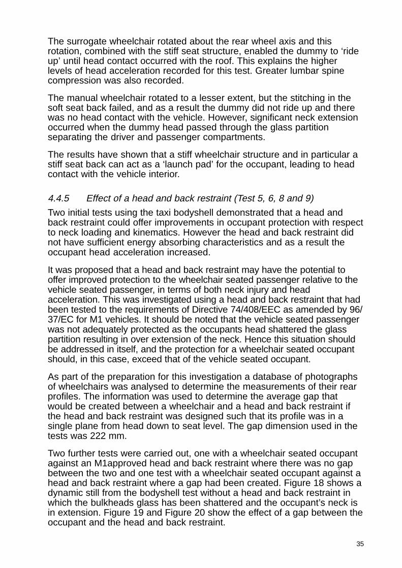
4.4.5 Effect of a head and back restraint (Test 5, 6, 8 and 9)
Two initial tests using the taxi bodyshell demonstrated that a head andback restraint could offer improvements in occupant protection with respectto neck loading and kinematics. However the head and back restraint didnot have sufficient energy absorbing characteristics and as a result theoccupant head acceleration increased.
It was proposed that a head and back restraint may have the potential tooffer improved protection to the wheelchair seated passenger relative to thevehicle seated passenger, in terms of both neck injury and headacceleration. This was investigated using a head and back restraint that hadbeen tested to the requirements of Directive 74/408/EEC as amended by 96/37/EC for M1 vehicles. It should be noted that the vehicle seated passengerwas not adequately protected as the occupants head shattered the glasspartition resulting in over extension of the neck. Hence this situation shouldbe addressed in itself, and the protection for a wheelchair seated occupantshould, in this case, exceed that of the vehicle seated occupant.
As part of the preparation for this investigation a database of photographsof wheelchairs was analysed to determine the measurements of their rearprofiles. The information was used to determine the average gap thatwould be created between a wheelchair and a head and back restraint ifthe head and back restraint was designed such that its profile was in asingle plane from head down to seat level. The gap dimension used in thetests was 222 mm.
Two further tests were carried out, one with a wheelchair seated occupantagainst an M1approved head and back restraint where there was no gapbetween the two and one test with a wheelchair seated occupant against ahead and back restraint where a gap had been created. Figure 18 shows adynamic still from the bodyshell test without a head and back restraint inwhich the bulkheads glass has been shattered and the occupant’s neck isin extension. Figure 19 and Figure 20 show the effect of a gap between theoccupant and the head and back restraint.
36
Figure 18a Set up with no headand back restraint
Figure 18b Wheelchair occupantwith no head and backrestraint
Figure 20a Set up with a gapbetween head and backrestraint and occupant
Figure 20b Wheelchair occupantwith a gap betweenhead and back restraintand occupant
Figure 19a Set up with a head andback restraint
Figure 19b Wheelchair occupantwith a head and backrestraint
37
Figure 18, in which the wheelchair occupant does not have a head and backrestraint shows how the neck over extends. When a head and back restraintis put in place the neck extension is controlled. In contrast to this, when agap is present between the wheelchair and the head and back restraint, theoccupant’s head rotates before making contact with the head and backrestraint resulting in a loaded neck extension, as shown in Figure 20. Thissituation also results in very high head accelerations for the occupant.
Based on the results of these tests, the addition of a head and backrestraint appears to improve the safety for a rear facing occupant but it isnecessary to ensure that there is no gap between the wheelchair and thehead and back restraint for maximum benefit.
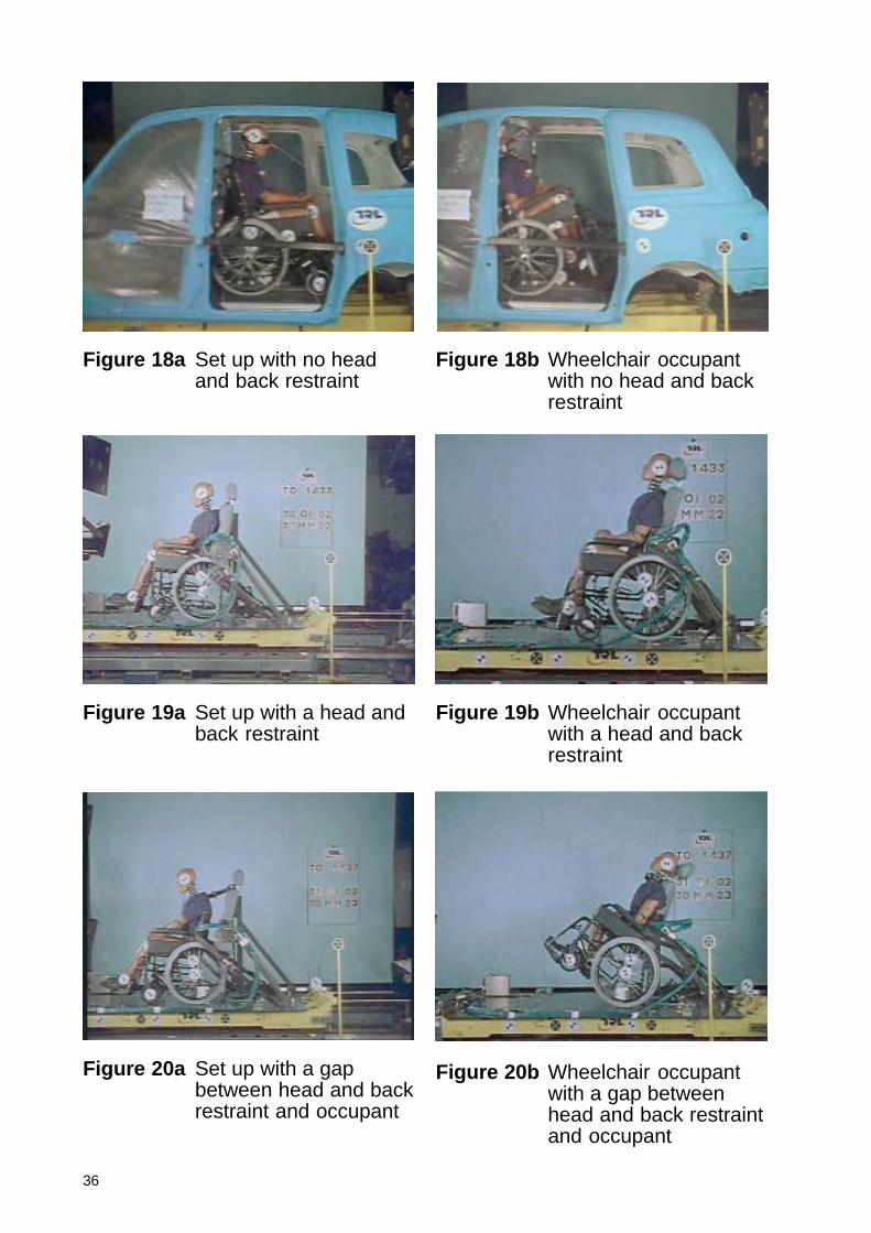
4.4.6 Head and back restraint strength (Test 10)
The sled test described in Section 4.3.2 was carried out to define dynamicstrength requirements for a rear facing wheelchair head and back restraintin M1 and M2 vehicles.
The overall force with inertia compensation was calculated for each loadplate and this was used to determine the total load acting on the threeplates at any one time. The results are shown in Table 9.
Table 9 Head and back restraint loads
Force plate Peak force (kN)
Top 7
Middle 42
Bottom 53
Maximum load 91
The results of this test show that a rear facing wheelchair head and backrestraint in an M1 or M2 vehicle must have sufficient strength to withstandloads up to 91kN.
4.4.7 Anchorage loadingThis was not examined for M1 and M2 rear facing.
4.4.8 Occupant space requirementsThis was not examined for M1 and M2 rear facing.
4.5 ConclusionsThe principal findings for rear facing in M1 and M2 vehicles areprovided in the following summary. A formal set of recommendations aregiven in Section 11.

38
Head and back restraint:
� A head and back restraint tested to the requirements of Directive 74/408/EEC as amended by 96/37/EC for M1 vehicles is required for rear facingoccupants, in a single plane from head down to seat level in order toprevent relative displacement between the head and torso. The head andback restraint should meet the requirements for energy absorption andstrength in ECE Regulation 17.
� It is important that there is no gap between the wheelchair and headand the head and back restraint.
� The head and back restraint needs to withstand a horizontal loadingof 100kN.
39
5 M3 forward facing
5.1 Simulation work
Ten model analyses of the numerical model were completed and aredescribed in detail in Appendix 2. Various combinations of wheelchair,dummy and restraints were investigated.
The simulation work suggested that there would be a low likelihood ofserious injury in this type of impact as the dummy loads were well belowthe injury thresholds in most cases. The wheelchair tie-down system hadlittle effect on dummy loading when the diagonal part of the belt wasmounted in the upper location. The effect of using floor mounted occupantrestraints was not investigated in the simulation work.
5.2 Scope
To further investigate forward facing occupants in M3 category vehicles aseries of dynamic tests were carried out. The findings from the simulationwork were considered when planning the test programme.
The primary objective for forward facing occupants in M3 category vehicleswas to assess whether the wheelchair seated occupant was provided withan equivalent level of safety as the vehicle seated occupant, through theuse of instrumented dummies to compare the occupant loading.
In the dynamic testing, along with a comparison of the safety of vehicle andwheelchair seated passengers the different combinations of wheelchairrestraint and occupant restraint geometry were investigated. This wasexamined to determine whether there was a negative effect on theprotection to the occupant. Wheelchair stiffness and occupant size werealso investigated.
The effect of a head and back restraint was then investigated to determinewhether this could improve the protection provided for the occupant withrespect to neck extension and movement in rebound.
In order to set requirements for vehicles, the occupant space requiredwithin the vehicle was examined along with the loads that the vehicleanchorages would have to withstand.
5.3 Test configuration
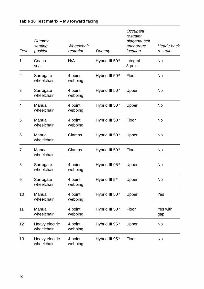
In order to investigate M3 vehicle requirements, thirteen sled tests werecarried out with various configurations (see test matrix, Table 10).
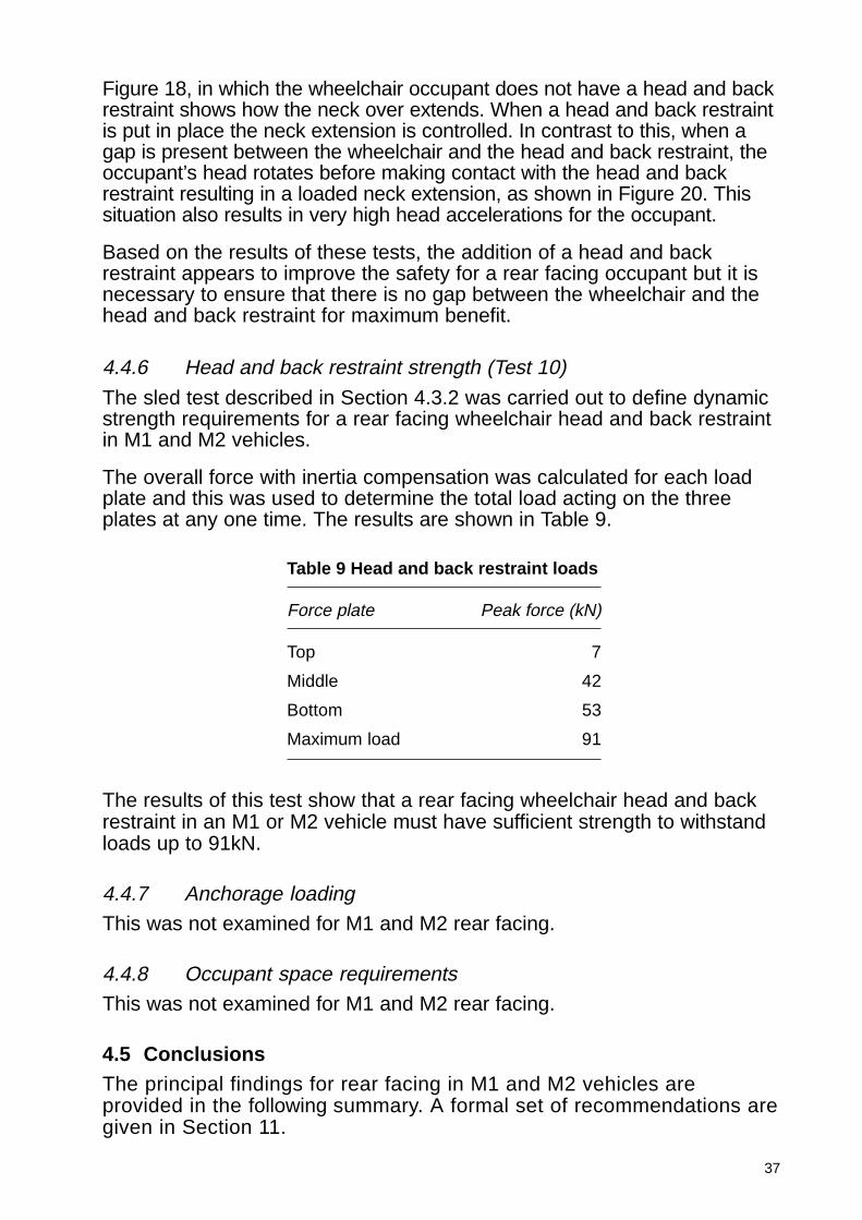
5.3.1 Occupant loadingTests 1 - 11 concerned occupant loading in M3 vehicles. A vehicle seatedbaseline test was completed for comparative purposes using a Hybrid III50th percentile dummy in a commercially available coach seat that includedan integrated three-point occupant restraint and a head restraint. This isshown in Figure 21. A series of wheelchair seated tests then followed toinvestigate the issues outlined in the scope. Figure 22 shows a typical setup for the wheelchair seated occupant.
40
Table 10 Test matrix – M3 forward facing
Occupantrestraint
Dummy diagonal beltseating Wheelchair anchorage Head / back
Test position restraint Dummy location restraint
1 Coach N/A Hybrid III 50th Integral Noseat 3 point
2 Surrogate 4 point Hybrid III 50th Floor Nowheelchair webbing
3 Surrogate 4 point Hybrid III 50th Upper Nowheelchair webbing
4 Manual 4 point Hybrid III 50th Upper Nowheelchair webbing
5 Manual 4 point Hybrid III 50th Floor Nowheelchair webbing
6 Manual Clamps Hybrid III 50th Upper Nowheelchair
7 Manual Clamps Hybrid III 50th Floor Nowheelchair
8 Surrogate 4 point Hybrid III 95th Upper Nowheelchair webbing
9 Surrogate 4 point Hybrid III 5th Upper Nowheelchair webbing
10 Manual 4 point Hybrid III 50th Upper Yeswheelchair webbing
11 Manual 4 point Hybrid III 50th Floor Yes withwheelchair webbing gap
12 Heavy electric 4 point Hybrid III 95th Upper Nowheelchair webbing
13 Heavy electric 4 point Hybrid III 95th Floor Nowheelchair webbing

41
5.3.2 Vehicle loading
Tests 12 and 13 investigated the loading on the vehicle anchorages. Twodifferent occupant diagonal belt systems were used, one with a floormounted diagonal anchorage and one with an upper mounted diagonalanchorage. The wheelchair was restrained with a four-point webbing tiedown system. These set ups are shown in Figure 23 and Figure 24. TheHybrid III 95th percentile dummy was seated in a heavy electric wheelchairas this represented the likely worst case for the restraint anchorage loads.
Figure 23 Set up with an upperlocation for the diagonalbelt anchorage
Figure 24 Set up with a floorlocation for the diagonalbelt anchorage
Figure 21 M3 forward facing -vehicle seated
Figure 22 M3 forward facingwheelchair seated
5.3.3 Sled configuration
The vehicle environment for a coach was set up on the sled. A productionmodel coach seat was used for the vehicle seated occupant test. The seathad an integrated 3-point restraint system.
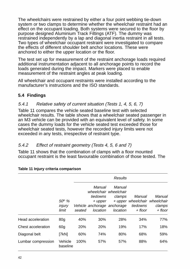
42
The wheelchairs were restrained by either a four point webbing tie-downsystem or two clamps to determine whether the wheelchair restraint had aneffect on the occupant loading. Both systems were secured to the floor bypurpose designed Aluminium Track Fittings (ATF). The dummy wasrestrained independently by a lap and diagonal inertia restraint in all tests.Two types of wheelchair occupant restraint were investigated to comparethe effects of different shoulder belt anchor locations. These wereanchored to either the upper location or the floor.
The test set up for measurement of the restraint anchorage loads requiredadditional instrumentation adjacent to all anchorage points to record theloads generated during the impact. Markers were placed to enablemeasurement of the restraint angles at peak loading.
All wheelchair and occupant restraints were installed according to themanufacturer’s instructions and the ISO standards.
5.4 Findings
5.4.1 Relative safety of current situation (Tests 1, 4, 5, 6, 7)Table 11 compares the vehicle seated baseline test with selectedwheelchair results. The table shows that a wheelchair seated passenger inan M3 vehicle can be provided with an equivalent level of safety. In somecases the dummy loads for the vehicle seated test exceeded those forwheelchair seated tests, however the recorded injury limits were notexceeded in any tests, irrespective of restraint type.
5.4.2 Effect of restraint geometry (Tests 4, 5, 6 and 7)
Table 11 shows that the combination of clamps with a floor mountedoccupant restraint is the least favourable combination of those tested. The
Table 11 Injury criteria comparison
Results
Manual Manualwheelchair wheelchair
tiedowns clamps Manual Manual50th % + upper + upper wheelchair wheelchairinjury Vehicle anchorage anchorage tiedowns clampslimit seated location location + floor + floor
Head acceleration 80g 40% 30% 28% 34% 77%
Chest acceleration 60g 20% 20% 19% 17% 18%
Diagonal belt [7kN] 60% 74% 80% 68% 59%
Lumbar compression Vehicle 100% 57% 57% 88% 64%baseline
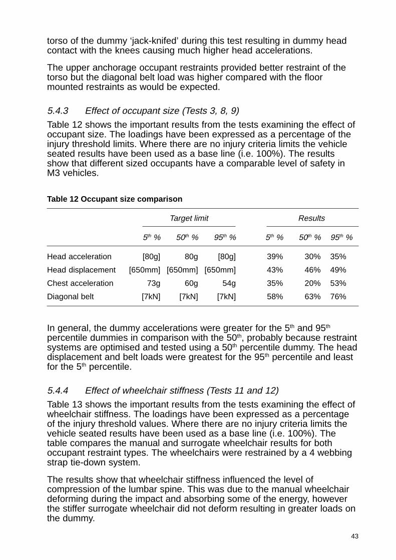
43
torso of the dummy ‘jack-knifed’ during this test resulting in dummy headcontact with the knees causing much higher head accelerations.
The upper anchorage occupant restraints provided better restraint of thetorso but the diagonal belt load was higher compared with the floormounted restraints as would be expected.
5.4.3 Effect of occupant size (Tests 3, 8, 9)
Table 12 shows the important results from the tests examining the effect ofoccupant size. The loadings have been expressed as a percentage of theinjury threshold limits. Where there are no injury criteria limits the vehicleseated results have been used as a base line (i.e. 100%). The resultsshow that different sized occupants have a comparable level of safety inM3 vehicles.
Table 12 Occupant size comparison
Target limit Results
5th % 50th % 95th % 5th % 50th % 95th %
Head acceleration [80g] 80g [80g] 39% 30% 35%
Head displacement [650mm] [650mm] [650mm] 43% 46% 49%
Chest acceleration 73g 60g 54g 35% 20% 53%
Diagonal belt [7kN] [7kN] [7kN] 58% 63% 76%
In general, the dummy accelerations were greater for the 5th and 95th
percentile dummies in comparison with the 50th, probably because restraintsystems are optimised and tested using a 50th percentile dummy. The headdisplacement and belt loads were greatest for the 95th percentile and leastfor the 5th percentile.
5.4.4 Effect of wheelchair stiffness (Tests 11 and 12)
Table 13 shows the important results from the tests examining the effect ofwheelchair stiffness. The loadings have been expressed as a percentageof the injury threshold values. Where there are no injury criteria limits thevehicle seated results have been used as a base line (i.e. 100%). Thetable compares the manual and surrogate wheelchair results for bothoccupant restraint types. The wheelchairs were restrained by a 4 webbingstrap tie-down system.
The results show that wheelchair stiffness influenced the level ofcompression of the lumbar spine. This was due to the manual wheelchairdeforming during the impact and absorbing some of the energy, howeverthe stiffer surrogate wheelchair did not deform resulting in greater loads onthe dummy.
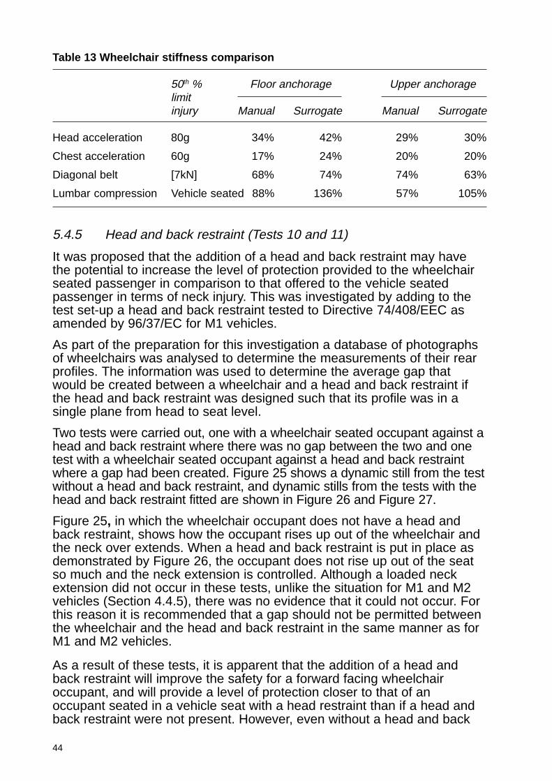
44
5.4.5 Head and back restraint (Tests 10 and 11)
It was proposed that the addition of a head and back restraint may havethe potential to increase the level of protection provided to the wheelchairseated passenger in comparison to that offered to the vehicle seatedpassenger in terms of neck injury. This was investigated by adding to thetest set-up a head and back restraint tested to Directive 74/408/EEC asamended by 96/37/EC for M1 vehicles.
As part of the preparation for this investigation a database of photographsof wheelchairs was analysed to determine the measurements of their rearprofiles. The information was used to determine the average gap thatwould be created between a wheelchair and a head and back restraint ifthe head and back restraint was designed such that its profile was in asingle plane from head to seat level.
Two tests were carried out, one with a wheelchair seated occupant against ahead and back restraint where there was no gap between the two and onetest with a wheelchair seated occupant against a head and back restraintwhere a gap had been created. Figure 25 shows a dynamic still from the testwithout a head and back restraint, and dynamic stills from the tests with thehead and back restraint fitted are shown in Figure 26 and Figure 27.
Figure 25, in which the wheelchair occupant does not have a head andback restraint, shows how the occupant rises up out of the wheelchair andthe neck over extends. When a head and back restraint is put in place asdemonstrated by Figure 26, the occupant does not rise up out of the seatso much and the neck extension is controlled. Although a loaded neckextension did not occur in these tests, unlike the situation for M1 and M2vehicles (Section 4.4.5), there was no evidence that it could not occur. Forthis reason it is recommended that a gap should not be permitted betweenthe wheelchair and the head and back restraint in the same manner as forM1 and M2 vehicles.
As a result of these tests, it is apparent that the addition of a head andback restraint will improve the safety for a forward facing wheelchairoccupant, and will provide a level of protection closer to that of anoccupant seated in a vehicle seat with a head restraint than if a head andback restraint were not present. However, even without a head and back
Table 13 Wheelchair stiffness comparison
50th % Floor anchorage Upper anchoragelimitinjury Manual Surrogate Manual Surrogate
Head acceleration 80g 34% 42% 29% 30%
Chest acceleration 60g 17% 24% 20% 20%
Diagonal belt [7kN] 68% 74% 74% 63%
Lumbar compression Vehicle seated 88% 136% 57% 105%
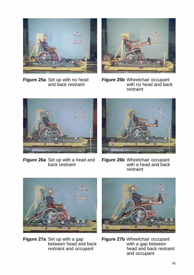
45
Figure 27a Set up with a gapbetween head and backrestraint and occupant
Figure 27b Wheelchair occupantwith a gap betweenhead and back restraintand occupant
Figure 25a Set up with no headand back restraint
Figure 25b Wheelchair occupantwith no head and backrestraint
Figure 26a Set up with a head andback restraint
Figure 26b Wheelchair occupantwith a head and backrestraint
46
restraint all injury criteria are below the conventional threshold values,although it should be considered that wheelchair users may have a lowertolerance to injury than indicated by the conventional threshold values.
It is necessary to ensure that there is no gap between the wheelchair andthe head and back restraint to gain maximum benefit. The same conclusionwould apply to a vehicle seated occupant and their head restraint.
5.4.6 Head and back restraint strength
This was not examined for M3 forward facing.
5.4.7 Anchorage loadings (Tests 12 and 13)
Two tests as detailed in 5.3.2 investigated the loading on the vehicleanchorages.
All the forces measured in these tests were resolved to 45 degrees toprovide consistent recommendations for the necessary anchoragestrengths in vehicles. Table 14 shows the resolved forces.
Table 14 M3 forward facing – restraint anchorage loads
Load (kN)
Wheelchair tiedown - front 5
Wheelchair tiedown - rear 20
Dummy restraint - lower - buckle side 19
Dummy restraint - lower - shoulder belt side 16
Dummy restraint – upper anchorage 5
5.4.8 Occupant space requirements (Tests 2 - 7)
Occupant injuries can be reduced if sufficient space is provided within thevehicle to prevent occupant contact with the vehicle interior.
Figure 28 shows the minimum space required for the head, knee and ankleof a 50th percentile occupant travelling in a manual wheelchair restrained byeither four point webbing straps or clamps, and representing both floor andupper anchorage mounted shoulder belts. The red section represents thespace required for the head, the green section represents the spacerequired for the knee and the blue section represents the space required forthe ankle. The black vertical line indicates the plane of the upper anchorageposition and the black horizontal line indicates the plane of the ground.
The minimum vehicle space requirement will be the perimeter of thecombined shape of these areas.
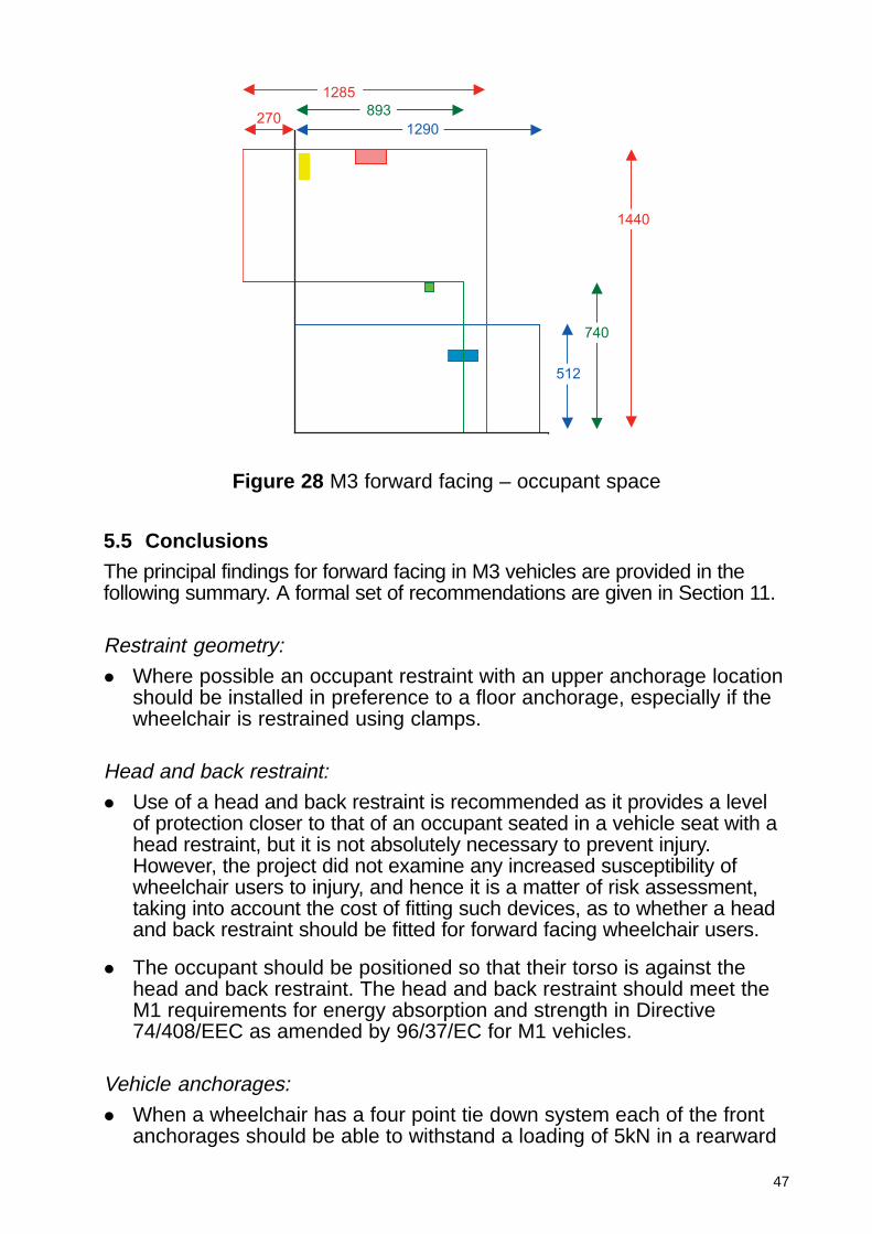
47
1285
893
1290270
1440
740
512
Figure 28 M3 forward facing – occupant space
5.5 Conclusions
The principal findings for forward facing in M3 vehicles are provided in thefollowing summary. A formal set of recommendations are given in Section 11.
Restraint geometry:
� Where possible an occupant restraint with an upper anchorage locationshould be installed in preference to a floor anchorage, especially if thewheelchair is restrained using clamps.
Head and back restraint:
� Use of a head and back restraint is recommended as it provides a levelof protection closer to that of an occupant seated in a vehicle seat with ahead restraint, but it is not absolutely necessary to prevent injury.However, the project did not examine any increased susceptibility ofwheelchair users to injury, and hence it is a matter of risk assessment,taking into account the cost of fitting such devices, as to whether a headand back restraint should be fitted for forward facing wheelchair users.
� The occupant should be positioned so that their torso is against thehead and back restraint. The head and back restraint should meet theM1 requirements for energy absorption and strength in Directive74/408/EEC as amended by 96/37/EC for M1 vehicles.
Vehicle anchorages:
� When a wheelchair has a four point tie down system each of the frontanchorages should be able to withstand a loading of 5kN in a rearward
48
and upward direction at an angle of 45 degrees to the horizontal. Eachof the rear anchorages should be able to withstand a load of 20kNapplied in a forward and upward direction at an angle of 45 degrees tothe horizontal.
� The anchorages of an occupant restraint system should be able towithstand 5kN at the upper anchorage applied forward and downwardat a 45 degree angle to the horizontal and 20kN at each of the flooranchorages applied in a forward and upward direction at an angle of 45degrees to the horizontal.
Occupant space:
� Based on an enclosing area summarising the measurements given inFigure 28, any wheelchair space should comply with the followingrequirements:
A wheelchair space shall not be less than:
� 1300mm measured in the longitudinal plane of the vehicle up to aheight of 1500mm;
� 1600mm measured in the longitudinal plane of the vehicle up to aheight of 750mm (if contact between the lower extremities and thevehicle interior is to be avoided).

49
6 M3 rear facing
6.1 Simulation study
Six analyses of the numerical model were carried out and these aredescribed in detail in Appendix 2.
The simulation work suggested that the occupant could experience highlevels of neck bending and chest acceleration if seated in the surrogatewheelchair. The reason for this observation was that the stiff wheelchairstructure keeps the dummy back away from the back restraint, henceallowing more relative rearward motion between the head and shoulders.
6.2 Scope
To further investigate rear facing occupants in M3 category vehicles aseries of dynamic tests were carried out. The findings from the simulationwork were considered when planning the test programme.
The primary objective for rear facing occupants in M3 vehicles was toassess whether the wheelchair seated occupant was provided with thesame level of protection as the vehicle seated occupant, through the use ofinstrumented dummies to compare the loading to the occupant.
6.3 Test configuration
In order to investigate M3 vehicle requirements six sled tests were carriedout with various configurations as shown in the test matrix, Table 15.
6.3.1 Occupant loading
Occupant loading was investigated in tests 1 – 5. A vehicle seatedbaseline test was completed for comparative purposes using anunrestrained Hybrid III 50th percentile dummy in a commercially availablerear facing fold down seat as shown in Figure 29. Figure 30 shows atypical set up for the wheelchair seated occupant in which the wheelchairand dummy are both unrestrained.
6.3.2 Vehicle loading
Test 6 examined the loading on a head and back restraint in order to definestrength requirements for rear facing head and back restraints in M3category vehicles. A 50th percentile Hybrid II dummy was seated in a heavyelectric wheelchair and the wheelchair was positioned rear facing againstthree force measuring plates that corresponded to the dummy head, torsoand base of the wheelchair. The set up is shown in Figure 31.
6.3.3 Sled configuration
Various M3 vehicle environments were created on the sled. For the vehicle
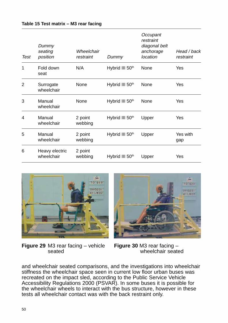
50
Table 15 Test matrix – M3 rear facing
Occupantrestraint
Dummy diagonal beltseating Wheelchair anchorage Head / back
Test position restraint Dummy location restraint
1 Fold down N/A Hybrid III 50th None Yesseat
2 Surrogate None Hybrid III 50th None Yeswheelchair
3 Manual None Hybrid III 50th None Yeswheelchair
4 Manual 2 point Hybrid III 50th Upper Yeswheelchair webbing
5 Manual 2 point Hybrid III 50th Upper Yes withwheelchair webbing gap
6 Heavy electric 2 pointwheelchair webbing Hybrid III 50th Upper Yes
Figure 29 M3 rear facing – vehicleseated
Figure 30 M3 rear facing –wheelchair seated
and wheelchair seated comparisons, and the investigations into wheelchairstiffness the wheelchair space seen in current low floor urban buses wasrecreated on the impact sled, according to the Public Service VehicleAccessibility Regulations 2000 (PSVAR). In some buses it is possible forthe wheelchair wheels to interact with the bus structure, however in thesetests all wheelchair contact was with the back restraint only.
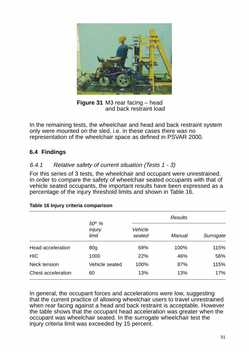
51
In the remaining tests, the wheelchair and head and back restraint systemonly were mounted on the sled, i.e. in these cases there was norepresentation of the wheelchair space as defined in PSVAR 2000.
6.4 Findings
6.4.1 Relative safety of current situation (Tests 1 - 3)
For this series of 3 tests, the wheelchair and occupant were unrestrained.In order to compare the safety of wheelchair seated occupants with that ofvehicle seated occupants, the important results have been expressed as apercentage of the injury threshold limits and shown in Table 16.
Figure 31 M3 rear facing – headand back restraint load
Table 16 Injury criteria comparison
Results50th %injury Vehiclelimit seated Manual Surrogate
Head acceleration 80g 69% 100% 115%
HIC 1000 22% 46% 56%
Neck tension Vehicle seated 100% 87% 115%
Chest acceleration 60 13% 13% 17%
In general, the occupant forces and accelerations were low, suggestingthat the current practice of allowing wheelchair users to travel unrestrainedwhen rear facing against a head and back restraint is acceptable. Howeverthe table shows that the occupant head acceleration was greater when theoccupant was wheelchair seated. In the surrogate wheelchair test theinjury criteria limit was exceeded by 15 percent.
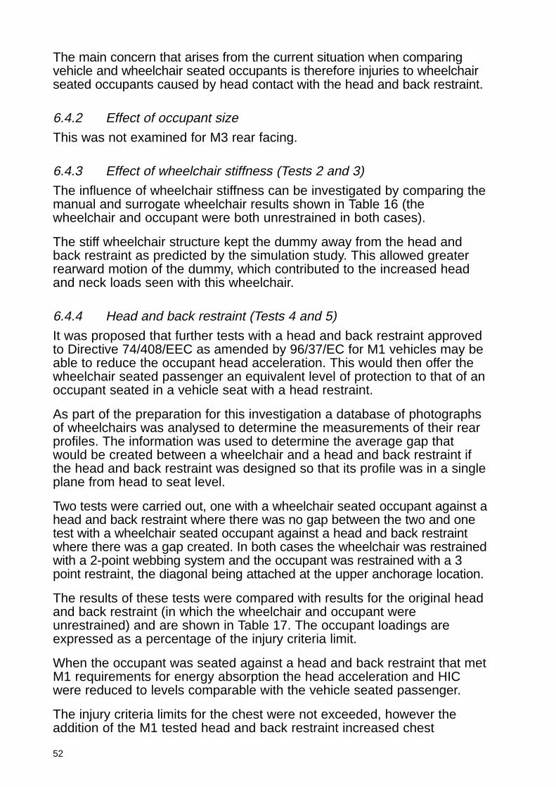
52
The main concern that arises from the current situation when comparingvehicle and wheelchair seated occupants is therefore injuries to wheelchairseated occupants caused by head contact with the head and back restraint.
6.4.2 Effect of occupant size
This was not examined for M3 rear facing.
6.4.3 Effect of wheelchair stiffness (Tests 2 and 3)
The influence of wheelchair stiffness can be investigated by comparing themanual and surrogate wheelchair results shown in Table 16 (thewheelchair and occupant were both unrestrained in both cases).
The stiff wheelchair structure kept the dummy away from the head andback restraint as predicted by the simulation study. This allowed greaterrearward motion of the dummy, which contributed to the increased headand neck loads seen with this wheelchair.
6.4.4 Head and back restraint (Tests 4 and 5)
It was proposed that further tests with a head and back restraint approvedto Directive 74/408/EEC as amended by 96/37/EC for M1 vehicles may beable to reduce the occupant head acceleration. This would then offer thewheelchair seated passenger an equivalent level of protection to that of anoccupant seated in a vehicle seat with a head restraint.
As part of the preparation for this investigation a database of photographsof wheelchairs was analysed to determine the measurements of their rearprofiles. The information was used to determine the average gap thatwould be created between a wheelchair and a head and back restraint ifthe head and back restraint was designed so that its profile was in a singleplane from head to seat level.
Two tests were carried out, one with a wheelchair seated occupant against ahead and back restraint where there was no gap between the two and onetest with a wheelchair seated occupant against a head and back restraintwhere there was a gap created. In both cases the wheelchair was restrainedwith a 2-point webbing system and the occupant was restrained with a 3point restraint, the diagonal being attached at the upper anchorage location.
The results of these tests were compared with results for the original headand back restraint (in which the wheelchair and occupant wereunrestrained) and are shown in Table 17. The occupant loadings areexpressed as a percentage of the injury criteria limit.
When the occupant was seated against a head and back restraint that metM1 requirements for energy absorption the head acceleration and HICwere reduced to levels comparable with the vehicle seated passenger.
The injury criteria limits for the chest were not exceeded, however theaddition of the M1 tested head and back restraint increased chest
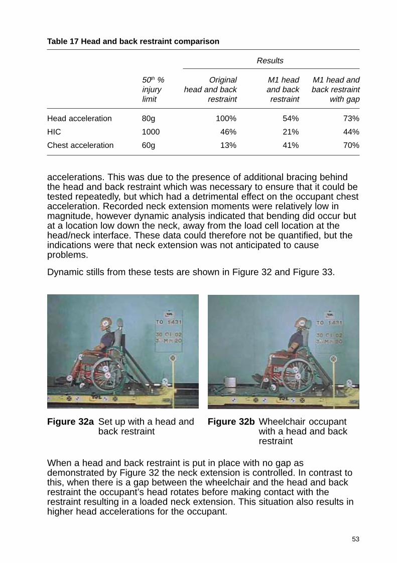
53
accelerations. This was due to the presence of additional bracing behindthe head and back restraint which was necessary to ensure that it could betested repeatedly, but which had a detrimental effect on the occupant chestacceleration. Recorded neck extension moments were relatively low inmagnitude, however dynamic analysis indicated that bending did occur butat a location low down the neck, away from the load cell location at thehead/neck interface. These data could therefore not be quantified, but theindications were that neck extension was not anticipated to causeproblems.
Dynamic stills from these tests are shown in Figure 32 and Figure 33.
Table 17 Head and back restraint comparison
Results
50th % Original M1 head M1 head andinjury head and back and back back restraintlimit restraint restraint with gap
Head acceleration 80g 100% 54% 73%
HIC 1000 46% 21% 44%
Chest acceleration 60g 13% 41% 70%
Figure 32a Set up with a head andback restraint
Figure 32b Wheelchair occupantwith a head and backrestraint
When a head and back restraint is put in place with no gap asdemonstrated by Figure 32 the neck extension is controlled. In contrast tothis, when there is a gap between the wheelchair and the head and backrestraint the occupant’s head rotates before making contact with therestraint resulting in a loaded neck extension. This situation also results inhigher head accelerations for the occupant.
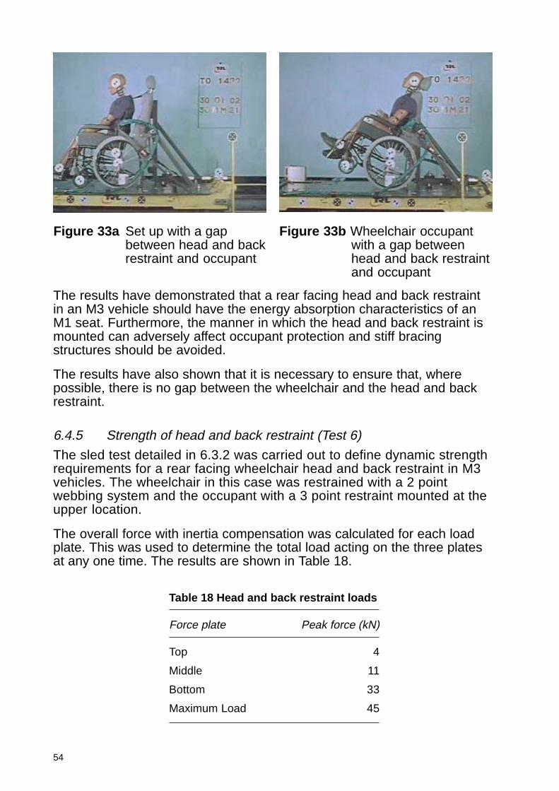
54
The results have demonstrated that a rear facing head and back restraintin an M3 vehicle should have the energy absorption characteristics of anM1 seat. Furthermore, the manner in which the head and back restraint ismounted can adversely affect occupant protection and stiff bracingstructures should be avoided.
The results have also shown that it is necessary to ensure that, wherepossible, there is no gap between the wheelchair and the head and backrestraint.
6.4.5 Strength of head and back restraint (Test 6)
The sled test detailed in 6.3.2 was carried out to define dynamic strengthrequirements for a rear facing wheelchair head and back restraint in M3vehicles. The wheelchair in this case was restrained with a 2 pointwebbing system and the occupant with a 3 point restraint mounted at theupper location.
The overall force with inertia compensation was calculated for each loadplate. This was used to determine the total load acting on the three platesat any one time. The results are shown in Table 18.
Table 18 Head and back restraint loads
Force plate Peak force (kN)
Top 4
Middle 11
Bottom 33
Maximum Load 45
Figure 33a Set up with a gapbetween head and backrestraint and occupant
Figure 33b Wheelchair occupantwith a gap betweenhead and back restraintand occupant
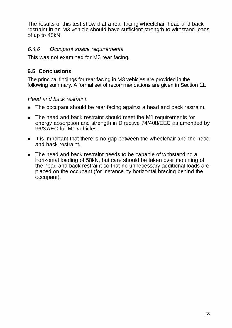
55
The results of this test show that a rear facing wheelchair head and backrestraint in an M3 vehicle should have sufficient strength to withstand loadsof up to 45kN.
6.4.6 Occupant space requirements
This was not examined for M3 rear facing.
6.5 Conclusions
The principal findings for rear facing in M3 vehicles are provided in thefollowing summary. A formal set of recommendations are given in Section 11.
Head and back restraint:
� The occupant should be rear facing against a head and back restraint.
� The head and back restraint should meet the M1 requirements forenergy absorption and strength in Directive 74/408/EEC as amended by96/37/EC for M1 vehicles.
� It is important that there is no gap between the wheelchair and the headand back restraint.
� The head and back restraint needs to be capable of withstanding ahorizontal loading of 50kN, but care should be taken over mounting ofthe head and back restraint so that no unnecessary additional loads areplaced on the occupant (for instance by horizontal bracing behind theoccupant).
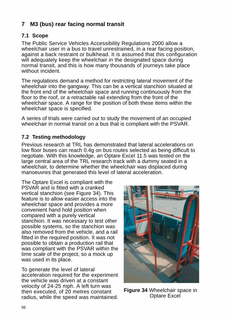
56
7 M3 (bus) rear facing normal transit
7.1 ScopeThe Public Service Vehicles Accessibility Regulations 2000 allow awheelchair user in a bus to travel unrestrained, in a rear facing position,against a back restraint or bulkhead. It is assumed that this configurationwill adequately keep the wheelchair in the designated space duringnormal transit, and this is how many thousands of journeys take placewithout incident.
The regulations demand a method for restricting lateral movement of thewheelchair into the gangway. This can be a vertical stanchion situated atthe front end of the wheelchair space and running continuously from thefloor to the roof, or a retractable rail extending from the front of thewheelchair space. A range for the position of both these items within thewheelchair space is specified.
A series of trials were carried out to study the movement of an occupiedwheelchair in normal transit on a bus that is compliant with the PSVAR.
7.2 Testing methodologyPrevious research at TRL has demonstrated that lateral accelerations onlow floor buses can reach 0.4g on bus routes selected as being difficult tonegotiate. With this knowledge, an Optare Excel 11.5 was tested on thelarge central area of the TRL research track with a dummy seated in awheelchair, to determine whether the wheelchair was displaced duringmanoeuvres that generated this level of lateral acceleration.
The Optare Excel is compliant with thePSVAR and is fitted with a crankedvertical stanchion (see Figure 34). Thisfeature is to allow easier access into thewheelchair space and provides a moreconvenient hand hold position whencompared with a purely verticalstanchion. It was necessary to test otherpossible systems, so the stanchion wasalso removed from the vehicle, and a railfitted in the required position. It was notpossible to obtain a production rail thatwas compliant with the PSVAR within thetime scale of the project, so a mock upwas used in its place.
To generate the level of lateralacceleration required for the experimentthe vehicle was driven at a constantvelocity of 24-25 mph. A left turn wasthen executed, of 20 metres constantradius, while the speed was maintained.
Figure 34 Wheelchair space inOptare Excel
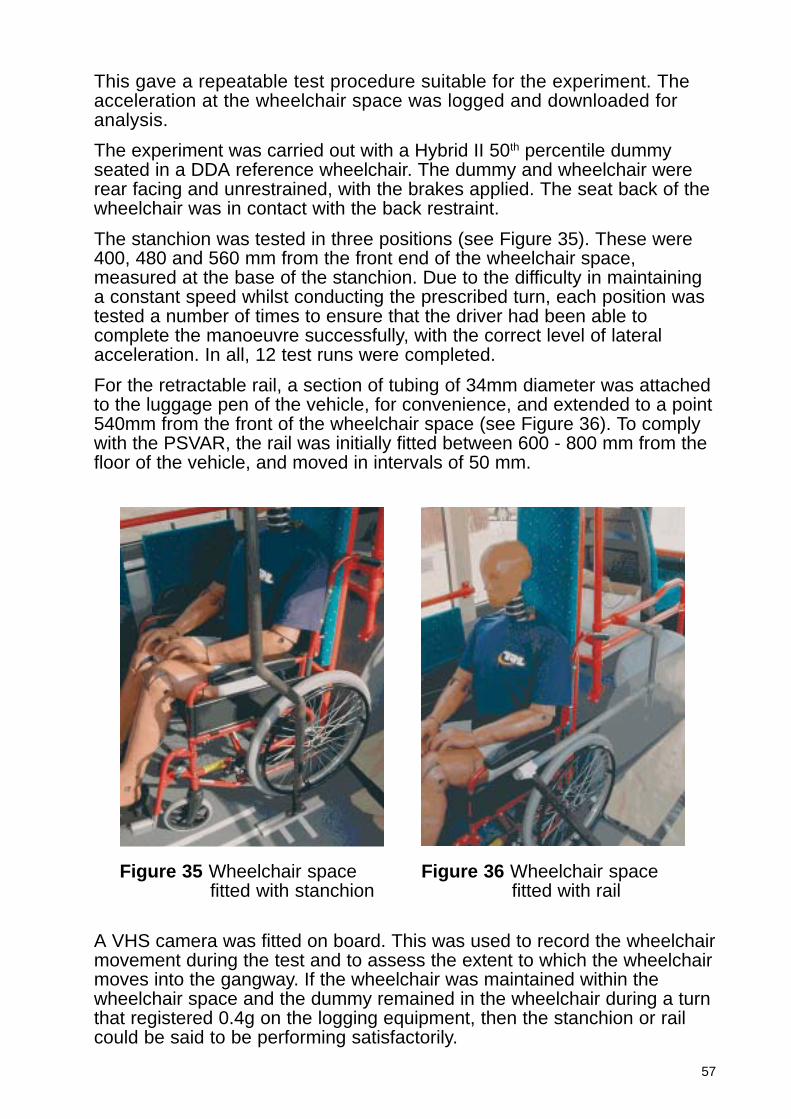
57
This gave a repeatable test procedure suitable for the experiment. Theacceleration at the wheelchair space was logged and downloaded foranalysis.
The experiment was carried out with a Hybrid II 50th percentile dummyseated in a DDA reference wheelchair. The dummy and wheelchair wererear facing and unrestrained, with the brakes applied. The seat back of thewheelchair was in contact with the back restraint.
The stanchion was tested in three positions (see Figure 35). These were400, 480 and 560 mm from the front end of the wheelchair space,measured at the base of the stanchion. Due to the difficulty in maintaininga constant speed whilst conducting the prescribed turn, each position wastested a number of times to ensure that the driver had been able tocomplete the manoeuvre successfully, with the correct level of lateralacceleration. In all, 12 test runs were completed.
For the retractable rail, a section of tubing of 34mm diameter was attachedto the luggage pen of the vehicle, for convenience, and extended to a point540mm from the front of the wheelchair space (see Figure 36). To complywith the PSVAR, the rail was initially fitted between 600 - 800 mm from thefloor of the vehicle, and moved in intervals of 50 mm.
A VHS camera was fitted on board. This was used to record the wheelchairmovement during the test and to assess the extent to which the wheelchairmoves into the gangway. If the wheelchair was maintained within thewheelchair space and the dummy remained in the wheelchair during a turnthat registered 0.4g on the logging equipment, then the stanchion or railcould be said to be performing satisfactorily.
Figure 35 Wheelchair spacefitted with stanchion
Figure 36 Wheelchair spacefitted with rail
58
7.3 Results
Both the stanchion and rail are designed to prevent movement of thewheelchair into the gangway, where it could become a hazard for thewheelchair passenger and standing passengers in the vicinity. This isnecessary in the Optare Excel and similar vehicles, because as the busturns left there is a weight transfer to the left of the wheelchair, adjacent tothe gangway. This reduces the grip of the wheels on the right hand side ofthe wheelchair, beside the wall. The mass can then pivot about the verticalaxis of the left rear wheel. This effect is exaggerated by the front wheels,which are on castors, and without brakes.
The film of the tests indicates that the motion described could occur whenlateral acceleration reached 0.29 - 0.3g, although movement into thegangway did not occur unless levels of acceleration reached 0.33 - 0.34g.It is only possible to give an approximation of when the motion occurred asthe accelerometer and video were not directly linked.
7.3.1 Wheelchair space fitted with a stanchionThe Public Service Vehicles Accessibility Regulations 2000 state that thebase of the stanchion must be between 400 and 560mm from the front ofthe wheelchair space. During the tests with the stanchion at 400mm almostno wheelchair movement was observed, even when the lateral accelerationrecorded in the vehicle reached 0.4g. The same was true when thestanchion was moved forward to 480mm. The wheelchair could not move,because there was only a short distance of approximately 50mm laterally,between the handrim on the left rear wheel and the stanchion. Thereforeas the wheelchair begins to rotate about the vertical axis of the wheel, thehandrim contacted the stanchion and the movement ceased.
When the stanchion was positioned at 560mm from the front of thewheelchair space greater movement occurred as the stanchion was aheadof the leading edge of the handrim. However the stanchion contacted thefront edge of the wheel and tyre and further movement was prevented. Atno time did the wheelchair cross the plane of the wheelchair space andmove into the gangway. As the stanchion was seen to perform satisfactorilyin these tests, whilst positioned at the extremes of the range allowable, itwas not necessary to conduct further tests outside this range.
7.3.2 Wheelchair space fitted with a railA retractable rail is permitted in the PSVAR in the place of a stanchion.This must extend at least 540mm from the front of the wheelchair spaceand be at a height between 600 and 800mm from the floor. A mock updevice was fitted in the bus and braced laterally so that it was capable ofbearing the load required. The rail was initially positioned within the heightrange described above.
At 600mm the rail did not perform well in separate tests where the peaklateral acceleration reached 0.35 and 0.4g. The wheelchair rotated aboutthe vertical axis of the left rear wheel but the rail did not restrain the

59
wheelchair due to the gap in the armrest, see Figure 37. The left frontwheel and foot plate partially intruded into the gangway. Further movementwas only prevented when the rail contacted the dummy leg.
The test was repeated with the rail at a height of 650mm. At this positionthe wheelchair did not move when the acceleration was 0.4g, because therail was at the same height as the padded armrest on the wheelchair.When the wheelchair began to move it quickly contacted the rail, whichprevented any movement into the gangway. The rail was then raised to700mm. This height exceeded any side structure on the wheelchair andduring the test there was significant wheelchair motion into the gangway.The wheelchair rotated about the vertical axis of the left rear wheel andpassed under the rail until it was arrested by contact with the forearm ofthe dummy, Figure 38. At this point, part of both the left front wheel andfoot plate were outside the designated wheelchair space and in thegangway. The rail was then raised to 800mm from the floor, the maximumheight allowed in the PSVAR. The wheelchair again rotated under the rail,this time resulting in the greatest excursion into the gangway of the vehicle.At the end of tests where peak lateral accelerations were in the range 0.33- 0.4g, the entire left foot plate and the left front wheel were outside thewheelchair space.
Figure 37 Post test with rail at600 mm above floor
Figure 38 Post test with rail at700 mm above floor
The tests described above were carried out with the rail at a height thatwas compliant with the PSVAR. It was apparent during these experimentsthat the rail was not performing satisfactorily at most of the heights tested,in the range allowed. At 700mm or above the reference wheelchair couldpass underneath the rail, therefore there was no benefit in conductingfurther tests above the 800mm upper limit. Instead, additional tests were
60
carried out with the rail below the lower limit, at 550mm from the floor.During these tests the rail performed well, and prevented the wheelchairfrom rotating into the gangway. The rail was more effective at this heightbecause as movement began the rail contacted the handrims andrestrained the wheelchair from further movement.
7.4 Conclusions
The results have shown that the reference wheelchair will move whenexposed to levels of lateral vehicle acceleration that are possible on busroutes. Furthermore the effectiveness of the available methods for restrictingthis movement is variable, and dependent on the location of the device.
During tests with a vertical stanchion, wheelchair movement was restrictedin all tests, when the position of the stanchion was varied within the rangeallowed. The level of peak lateral acceleration exceeded 0.4g in some ofthese tests, but the wheelchair did not move into the gangway. Theoptimum position for a stanchion is ahead of the vertical axis of the rearwheel as the wheelchair tends to pivot around this axis at levels ofacceleration that were approaching 0.35g. However it should not beforward of the leading edge of the rear wheel because it is desirable for thewheel handrim and stanchion to make contact.
The performance of the rail in these tests was of concern. The ability of thedevice to restrict wheelchair movement was highly dependent on its height.If the rail could interact with the side of the wheelchair after movementbegan then it could restrict the motion sufficiently to keep the wheelchairand dummy out of the gangway. However, when tests were carried out atdifferent heights allowed by the PSVAR, the wheelchair was able to rotateunderneath the rail when subjected to lateral vehicle accelerations of themagnitude possible on bus routes. Based on these findings, the use of asingle bar horizontal rail is not recommended, although a design with depthor some form of adjustment may be acceptable.
The results can only be used to give an indication of the performance ofthe stanchion or rail with respect to the DDA reference wheelchair only.Caution should be exercised when drawing conclusions for otherwheelchair types. For instance, the stanchion performed well due to itsposition in relation to the large rear wheel, enabling it to stop the pivotingaction of the wheelchair. The results may have been different for anattendant controlled wheelchair or an electric wheelchair with smaller rearwheels. The ability of the rail to restrict wheelchair movement was highlydependent on its height from the floor of the bus. It is therefore difficult tomake recommendations regarding the effectiveness of the device using asingle wheelchair type.
The only movement observed was a pivoting about the vertical axis of theleft rear wheel; at no time did the wheelchair move forward. The brakeperformance could have been a factor in the lack of forward excursion ofthe wheelchair. The brake mechanism of the reference wheelchair appearsto be more robust than that of a standard manual wheelchair. In these
61
tests, tyre pressure was set at the lower limit of the recommended inflationlevel. The action of the brake shoe pressing on the tyre makes correctinflation pressure important. In the real world wheelchair tyres may not befully inflated. Furthermore, there are occasions when a vehicle is likely tobe accelerating whilst executing a turn, for instance entering a roundabout.It was not appropriate to investigate the possible effects of vehicleacceleration during the manoeuvre, as this could not be done withsufficient repeatability. However, it is possible that there would be a weighttransfer to the front of the wheelchair, reducing the grip of the rear wheels.
In summary, the vertical stanchion appeared to provide a better means ofrestraining the wheelchair, although this conclusion requires validationagainst other wheelchair types, especially those with smaller wheels. Theperformance of the moveable horizontal rail was very dependent upon thedimensions of the wheelchair involved, and it is hard to see how thesituation could be improved. This type of restraint therefore gives rise forconcern, although again, tests with other designs of wheelchairs should becarried out before any actions are decided upon.
62
8 Information for regulatory impact assessment
8.1 Whelchair users
It is estimated that there are around 1,200,000 wheelchair users in thiscountry representing approximately 2% of the population. If wheelchairusers have the same social need to travel and the same ability to do sothen it would be reasonable to assume that in all modes of transportwheelchairs users may represent 2% of all travellers. There is insufficientinformation on which to compare the travel patterns of wheelchair userswith that of the population as a whole, nor is it possible to identify theproportion of wheelchair users who may transfer to a vehicle seat whentravelling. However, it is unlikely that wheelchair users as group travel tothe same extent as the population as a whole and we can be certain thatnot all will travel seated in a wheelchair. Furthermore, the travel patterns ofwheelchair users may change as more vehicles become wheelchairaccessible. In the absence of any information to the contrary it is assumedthat wheelchair users who travel seated in their wheelchair will be exposedto 50% of the transport risks compared to other road users (i.e. 1% of thepopulation). On this basis the overall exposure to travel risks may be takenas being proportionate to that of other road users for any type of vehiclethat may be wheelchair accessible.
8.2 Cars and taxis (M1)
Cars, taxis and private hire vehicles with no more than 8 passenger seatsare all M1 category vehicles1 . Accident data does not differentiate betweenthese vehicles and therefore they must be considered as a whole. As suchthey are all referred to as cars. Whilst there may be only a small proportionof private hire vehicles that are wheelchair accessible, many taxis arewheelchair accessible and there is a growing supply of wheelchairaccessible cars for private use, for patient transport and similar applications.
8.2.1 Accident data
For the year 2000 RAGB accident data shows 1,665 car drivers andpassengers killed and 18,054 seriously injured. This is a slight improvementon both the 94-98 baseline average of 1,762 and 21,492, and the 96-2000average of 1,730 and 20,071 respectively. If, in future, 1% of these arewheelchair users there is the potential for them to be involved in 180serious injuries and 16 fatalities per year based on the data for the year2000. The findings of this research project indicate that improvements areneeded if wheelchair users are to be afforded an equivalent level ofprotection to that of other vehicle occupants. This suggests that making nochanges is likely to result in a higher number of wheelchair user casualtiesthan is estimated here. However, there is no evidence to suggest that suchlevels of injury are occurring at present. This suggests that either currenttravel patterns are lower than they are estimated to be in the future or other
1 Excludes special purpose M1 vehicles
63
factors, such as the nature of the journeys undertaken or the wheelchairlocation in a vehicle, have an influence on the exposure to transport risks.
8.2.2 Vehicle design changes
M1 vehicles are already equipped with a means of securing a wheelchairand are fitted with a wheelchair occupant restraint. The significantadditional factors recommended for future designs include the provision ofa head and back restraint for rear facing occupants, technical requirementsbased on a more representative deceleration test pulse (see Section 2)and provision of an adequate space envelope in the vehicle. Therecommendations may lead to a fundamental re-appraisal by industry onthe design of wheelchair accessible vehicles particularly in the taxis sectorwhere traditionally vehicles are designed for a rear facing wheelchair user.
In order to provide an equivalent level of protection to that of a seatedpassenger, a wheelchair user, when rearward facing, must be provided witha head and back restraint with a padded surface meeting requirements forenergy absorption. In addition, there must be sufficient space for lower rearprotrusions on the wheelchair to pass under the head and back restraint toallow the wheelchair seat back to come close the head and back restraint.Where a wheelchair user is forward facing a head and back restraint,although highly desirable, is not essential and is therefore not considered(see 11.1). For both forward and rearward facing wheelchair users additionalprotection can be provided for the lower limbs but this goes further than thatprovided for other seated occupants and is therefore excluded. In the caseof vehicles designed for a particular individual for personal use, somerelaxation of the space requirement is possible so that some of the smallervehicles may continue to be used as effective personal transport forwheelchair users without compromising safety.
The deceleration test pulse used to evaluate the survivability of wheelchairusers within this project will involve some strengthening of vehiclestructures. This test pulse is not replicated in all legislation relating to M1vehicles but is expected to be the minimum standard in the near future.
8.2.3 Annual production estimates
Wheelchair accessible vehicles (M1) (forward facing) 3,000.
Taxis (M1) (rear facing) 3,000.
8.2.4 Cost estimates
Estimated cost of a head and back restraint for a rear-facing wheelchairarrangement: £400 per vehicle.
Additional structural strength M1 (anchorages or bulkhead supportinghead and back restraint): £ 20 per vehicle.
Additional cost of adjustable wheelchair occupant restraint: £5 pervehicle.
Total cost 3,000 (400 +20+5) + 3,000 (20+5) = 1,350,000 or 1.35 £m.
64
8.2.5 Casualty cost savings
From RAGB 2000 casualty costs are as follows: £1,144,890 per fatality,£128,650 per serious injury, and £9,920 per slight injury. The measuresproposed are aimed at improving the level of survivability and reducing theseverity of injuries in accidents. From the number of potential fatal andserious injuries it is expected that the measures taken may reduce fatalinjuries to serious, and serious injuries to slight, however, these measuresare an improvement over existing provisions and therefore the overallimprovement is taken to be 20%. Therefore the potential cost savings are:(16(1144890 – 128650) + 180(128650 – 9920)) x 20% giving a total of£7,526,248 or £7.53m.
8.3 Minibuses (M2)
Vehicles of category M2 include vehicles with more than eight passengersbut not exceeding 5 tonnes maximum mass. The majority of these vehiclesare mass produced minibuses with 9 to 16 seats and usually less than 4tonnes maximum mass. Vehicles of this type are popular in the community,Local Authority, health and voluntary transport sectors, many of which willbe wheelchair accessible.
8.3.1 Accident data
For the year 2000 RAGB accident data shows 11 passengers killed and 94seriously injured. This may be compared with both the 94-98 average of8.6 and 129, and the 96-2000 average of 8.4 and 126.4 respectively.Annual casualty numbers fluctuate widely with no particular trendemerging. On this basis the 96-2000 average is taken to be representativeof potential casualties. If, in future, 1% of these casualties are wheelchairusers there is the potential for them to be involved in 0.084 fatalities and1.264 serious injuries per year. The findings of this research projectindicate that improvements are needed if wheelchair users are to beafforded an equivalent level of protection to that of other vehicle occupants.This suggests that making no changes is likely to result in a higher numberof wheelchair user casualties than is estimated here.
8.3.2 Vehicle design changes
M2 vehicles are already equipped with a means of securing a wheelchairand are fitted with a wheelchair occupant restraint. The significantadditional factors recommended for future designs include technicalrequirements based on a more representative deceleration test pulse (seeSection 2) and potentially the need for more space in the vehicle.
The recommendations for M2 vehicles are the same as those for M1vehicles. It would be unusual to find a rearward facing wheelchairarrangement in such vehicles at present and the recommendation for ahead and back restraint would further discourage such an arrangementdue to the constraints of space and access. The effect of a new regulatoryproposal is therefore assessed for forward facing wheelchair users in line
65
with current practice. As with M1 vehicles a head and back restraint andprotection for the lower limbs is not considered to be essential.
The deceleration test pulse used to evaluate the survivability of wheelchairusers within this project will involve some strengthening of vehiclestructures. For M2 vehicles there is research evidence to suggest that thistest pulse should be adopted, but it is a significant departure from currentrequirements. Additional structural strength is likely to bring additionalcosts although these will be less when engineered from the outset as forvolume production vehicles or when part of a coach built structure. For thepurpose of costs it is assumed that vehicles will usually have a flexibleseating/ wheelchair arrangement and be capable of accommodating up to6 wheelchairs.
8.3.3 Annual registrations
A total of 10,000 vehicles are estimated to be registered annually of which2,000 are believed to be wheelchair accessible. It should be noted thatthese figures are based on M2 vehicles with no more than 16 passengerseats. The number of vehicles with more than 16 passenger seats withinthe M2 category is unknown but the number likely to be wheelchairaccessible and be required to have seat belts for other passengers isthought to be small.
8.3.4 Cost estimates
Additional structural strength: £120 per vehicle.
Additional cost of adjustable wheelchair occupant restraint: £30 pervehicle.
Cost of proposals 2000 x (120+30) = £300,000.
8.3.5 Casualty cost savings
From RAGB 2000 casualty costs are as follows: £1,144,890 per fatality,£128,650 per serious injury, and £9,920 per slight injury. The measuresproposed are aimed at improving the level of survivability and severity ofinjury accidents. From the number of potential fatal and serious injuries it isexpected that the measures taken may reduce fatal injuries to serious, andserious injuries to slight with a 20% improvement over existing provisions.The potential cost are: (0.084(1144890 – 128650) + 1.264(128650 – 9920))x 20% giving a total saving of £47,088.
8.4 Buses and coaches (M3)
Buses and coaches in this category are vehicles with more than 8passengers and exceeding 5 tonnes maximum mass. In less than 20 yearsall such buses used to provide local or scheduled services are required tobe wheelchair accessible.
66
Those that are designed to carry standing passengers are not required tobe fitted with seat belts and it is widely accepted that the way in which suchvehicles are used is satisfactory for a wheelchair user travelling rearwardfacing without any wheelchair or occupant restraint system (see Section 7).Regulations are already in place for these vehicles and nothing within therecommendations of this report is likely to add to vehicle costs.
For vehicles that do not carry standing passengers seat belts are required.In these vehicles a wheelchair user will normally travel forward facing andtherefore the cost of complying with revised technical requirements areconsidered for this arrangement only.
8.4.1 Accident data
RAGB provides casualty data for large buses and coaches. This includes M2vehicles with more than 16 passenger seats, although the number of suchvehicles that are wheelchair accessible and required to be fitted with seatbelts for passengers is considered to be small. This accident data is basedon some 67,000 public service vehicles of which it is estimated 13,000 willbe coaches. Previous data suggests that approximately half of passengercasualties relate to boarding or alighting. RAGB for the year 2000 shows 14fatalities and 513 serious passenger injuries and compares to the 94-98baseline average of 19 and 626, and the 96-2000 average of 13 and 546.Taking data for the year 2000 gives a potential of 7 fatalities and 257 seriousinjuries for moving vehicle injury accidents. However, not all such injuryaccidents will relate to coaches and not all coaches will be required to bewheelchair accessible based on current DfT regulations. If only 19% ofvehicles are coaches, the potential casualties by this mode are reduced to1.33 fatalities and 48.83 serious injuries. If, in future, 1% of these casualtiesare wheelchair users then there is the potential for them to be involved in0.0133 fatalities and 0.4883 serious injuries per year. The findings of thisresearch project indicate that improvements are needed if wheelchair usersare to be afforded an equivalent level of protection to that of other vehicleoccupants. This suggests that making no changes is likely to result in ahigher number of wheelchair user casualties than is estimated here.
8.4.2 Vehicle design changes
The provisions are very similar to those for cars and minibuses but basedon a deceleration test pulse that is identical that of European Directive 96/37/EC. The requirements are similar to PSVAR 2000 and Directive 2001/85/EC but the static test loads are higher and in the forward direction, andare more than 2 1/2 times current PSVAR requirements. On the plus side,the structural strength in the localised area of a wheelchair space may beeasier to accomplish in the custom built body of a coach and therefore theoverall effect of these changes is likely to be minimal.
8.4.3 Annual registrations
Wheelchair accessible coaches in the M3 category are estimated to be100 vehicles per annum. This is based on the requirements of the PSVAR
67
which require all coaches used on local and scheduled services to bewheelchair accessible by 2020. This is some 18 years hence, however,there are some 1300 vehicles involved and it is likely that the replacementcycle for vehicles used on these services will be shorter. For the purpose ofannual cost to industry it is anticipated that vehicles will be replaced over a13 year period at the rate of 100 per annum. Only one wheelchair spaceper vehicle is assumed to be fitted.
8.4.4 Cost estimates
An estimate of £20 per vehicle for some additional strengthening in thelocalised area of the anchorages and assuming one wheelchair spaceper vehicle.
Additional cost of adjustable wheelchair occupant restraint: £5 pervehicle.
Cost: 100 x (20+5) = £2500.
8.4.5 Casualty cost savings
From RAGB 2000 casualty costs are as follows: £1,144,890 per fatality,£128,650 per serious injury, and £9,920 per slight injury. The measuresproposed are aimed at improving the level of survivability and severity ofinjury accidents. From the number of potential fatal and serious injuries it isexpected that the measures taken may reduce fatal injuries to serious, andserious injuries to slight with a 20% improvement over existing provisions.The potential costs are: (0.0133(1144890 – 128650) + 0.4883(128650 –9920)) x 20% giving a total saving of £14298.
68
9 DiscussionMuch discussion of the results is presented in Sections 5 to 8 along withconclusions specific to the vehicles represented by those sections. Thissection is therefore confined to a discussion of factors common to thewhole study and observations of general and related interest.
The scope of the research was to compare the level of safety afforded topeople seated in their wheelchairs with that of people seated in vehicleseats, in M category vehicles. The results indicated that concerns arisefrom this comparison of injury levels for wheelchair seated occupants byover extension of the neck. This was the particularly the case for rearfacing occupants in all vehicles. It was demonstrated that the occupantneck kinematics can be significantly improved if the wheelchair ispositioned against a head and back restraint, however the head and backrestraint must meet the M1 requirements for energy absorption otherwisehigh head accelerations will result. In addition, there should be no gapbetween the wheelchair occupant and the head and back restraint formaximum protection. The benefits or disbenefits of a head and backrestraint in 2 planes were not investigated within the scope of this project.
The relative merits of an upper anchorage location for the occupant restraintdiagonal belt and a floor location were assessed for forward facingoccupants in all vehicle categories. In all cases the floor mounted anchoragegenerated higher loads on the occupant’s lumbar spine than the upperanchorage location, however this was usually still lower than the lumbarloads of the vehicle seated occupant. There are no injury criteria for lumbarloads and therefore it cannot be stated whether the occupant is at risk ofspinal injury or not purely on the basis of the dummy readings. However, asfar as is known, there is not a notable incidence of lumbar spine injury inaccidents involving restrained, forward facing occupants, indicating that thevehicle seated occupant does not appear to be at a high level of risk. As thewheelchair seated occupant sees lower lumbar loads than the vehicleseated occupant, it could be argued that the wheelchair occupant istherefore unlikely to be at risk, whichever anchorage method is used.
The reason that the lumbar loads recorded in wheelchair seated occupantsare lower than the vehicle seated occupant is due to compliance in thewheelchair structure, but wheelchairs are tending to become stiffer andstronger which is likely to increase lumbar loads significantly. The upperanchorage should therefore still be considered preferable. It should benoted that there is insufficient information on the performance ofwheelchairs to draw any further conclusions at this time.
In the case of rear facing M1 vehicles it was necessary to go further than acomparison of the wheelchair and vehicle seated occupants as under somecircumstances the vehicle seated occupants can be at risk of neck injury.The survivability of a wheelchair user was therefore taken as the objective.
The research also demonstrated that vehicle anchorages approved toautomotive regulations would not be sufficient to withstand the forcesgenerated by a wheelchair. Instead, a specific test would be required of the
69
wheelchair anchorage system applying the forces derived from thedynamic tests. The anchorage test loads recommended as a result of thiswork are up to 30kN for forward facing passengers in M1 & M2 categoryvehicles and up to 20kN for M3 vehicles. This compares with equivalentloads ranging from 7 to 17kN for M3 and M2 vehicles respectively asrequired by Directive 2001/85/EC and PSVAR 2000. There is a lesser butstill significant difference for rearward facing passengers. There are nostatic test loads specified in regulations for M1 vehicles.
The loads in the occupant restraints were found to be high (up to 7kN) incomparison to those of passengers in cars (See Table 3 and Table 20) andmight be expected to cause injury in over 50% of fit adults. Some carmanufacturers are known to limit the belt loads to 4 kN for this reason. Whilestandard passenger seat belts would be expected to carry loads of thismagnitude without failure, limitation of belt load is achieved at the expense ofincreased excursion and hence increased risk of contact injuries.
On the basis of the above, the objective of providing wheelchair seatedpassengers equivalent protection is achievable with the recommendedchanges in vehicle legislation.
Unfortunately, it is not possible to support these arguments with accidentdata concerning wheelchairs in vehicles as the current accident databasescannot identify whether the injured person was disabled. However, thedisabled population is increasing and the DDA will require that their safetyis fully considered when travelling in land based public transport.
In the longer term, there are areas outside the scope of this research thatwill need to be considered. For instance, the restraint of childrens’wheelchairs could raise other issues. Non-standard moulded seatingsystems in wheelchairs are frequently used and in these cases the childmay sometimes be in a reclined position.
The carriage of luggage was also not considered in the current projectalthough wheelchair users should not carry luggage at the rear of thewheelchair because it has been demonstrated that a gap between thewheelchair and head and back restraint should not be allowed.
It is also recognised that the research assumes the correct use of therestraint equipment. Misuse was not considered and would in any case bedifficult to prevent through legislation - this could be more appropriatelyaddressed through training or design.
Finally it had been decided that side impact would be excluded from thestudy although it is recognised that it may need to be considered for M1vehicles in particular at a later date.
It should also be borne in mind that the Hybrid III series of dummies areessentially representative of ‘fit’ adults whereas many disabled and elderlywheelchair occupants may be at greater risk of injury than indicated bythese dummies. Unfortunately, little data is available to address suchdifferences and indeed there are some other important differences
70
between the responses of these dummies and humans in accidents. Oneof these differences is that the spine representation used in frontal impactdummies (such as those used in this work) is less flexible than that of ahuman and hence may not respond in a truly biofidelic manner underimpact loading. Furthermore, these dummies were designed to be forwardfacing and it could therefore be argued that their biofidelity may becompromised in the rear facing tests. However the arguments presentedfor the dummy selection in Section 2.1.5 are robust, and the comparativenature of the tests means the results can be used to give an indication ofthe difference in occupant loading as a result of different systems.
71
10 Conclusions� Based on the research described in this report, wheelchair seated
passengers are not currently provided with an equivalent level of safetyas vehicle seated passengers.
� Changes in legislation are required to improve the safety of wheelchairseated passengers in all M category vehicles (except normal transitbuses).
� For normal transit buses the limitations of this research is such that noconclusions can be reached regarding improvements to the currentlegislative requirements in Great Britain.
� The presence of a head and back restraint is essential for rear facingoccupants and desirable for forward facing occupants to minimise neckinjuries. There should be no gap between the wheelchair occupant andthe head and back restraint.
� The diagonal part of the wheelchair occupant’s seat belt should beanchored to a third point at shoulder level to minimise lumbar spineloading and occupant excursion.
� There should be sufficient space in the vehicle to prevent occupantcontact with the interior unless appropriate protection is provided (seerecommendations for dimensions).
� Vehicle anchorages approved to automotive seat-belt regulations wouldnot be sufficient to withstand the forces generated by a wheelchair andoccupant where both are attached to a single anchorage. Instead aspecific test would be required of the anchorages, applying the forcesderived from the dynamic tests (see recommendations).
Recommendations for future research
� Future research should consider children. This could include anexamination of the wide range of wheelchairs available to children andhow they should be restrained.
� Only frontal impact was considered (for both forward and rear facingpassengers) within the scope of the project. It may be desirable toinvestigate side impact in future research.
� Restraint misuse was also outside the scope of this project, however, itwould be beneficial to reduce the potential for misuse. This could beachieved through engineering or educational means despite it beingdifficult to address through legislation as described earlier.

72
11 RecommendationsThe following are the recommendations for vehicle requirements asconcluded by TRL from the programme of numerical simulation and testingdescribed in this report. A corresponding full set of specifications based onthese recommendations (as developed by SAVE Transport Consultancy)are given in Appendix E.
11.1 M1 and M2 forward facing
Vehicle anchoragesIt is recommended that four vehicle anchorages or an equivalent system isprovided for each wheelchair location.
A four point anchorage system should comprise two for attachment at thefront of the wheelchair and two at the rear of the wheelchair. Alternatively itis acceptable to provide a system with only two attachment points on thewheelchair, either for convenience or to permit self docking systems. In thiscase these should be provided to allow attachment towards the rear of thewheelchair and should be capable of sustaining the same forces as theanchorages of the four anchorage system. Part of a back restraint or otherstructure may act upon the wheelchair as part of the system in order torestrain the wheelchair in both the forward and rearward direction.
It is recommended that the strength of the vehicle anchorages beassessed in a static strength test:
� Each of the rear anchorages should be able to sustain a force of 30kNwhen applied forwards and upwards at an angle of 45° to the horizontal.
� Each of the front anchorages (where provided) should be able tosustain a force of 5kN when applied rearwards and upwards at an angleof 45° to the horizontal.
� It is suggested that these forces should be sustained without failure fora minimum time period. A minimum period of 0.2 seconds would seemto be appropriate, based on the duration of typical impact pulses.
The relative location of the vehicle anchorages should be in accordancewith ISO 10542-2, although this standard only refers to 4 point tie-downsystems. For other types of tie-down system the manufacturersrecommendations should be followed.
While static strength requirements are recommended here based on thedynamic tests performed in this programme, an alternative dynamicstrength test, based on the dynamic test for wheelchair tie-downs in ISO10542-1 using a surrogate wheelchair and a 95th percentile adult maledummy, could be considered, although it was not part of this researchprogramme to develop such a test.

73
Occupant restraintIt is recommended that the occupant restraint is provided by a lap anddiagonal seatbelt. The lap belt part should be anchored to the floor. Due totheir potential to cause compressive injuries to the spine, shoulder beltsanchored to the floor are not normally recommended for vehicle seatingpositions. The research in this programme indicated that, although thelumbar spine forces for floor mounted shoulder belts were higher than forshoulder belts anchored at the upper location, they were still lower than forthe dummy seated in the normal vehicle seat. On this basis, either upperanchorage mounted or floor mounted shoulder belts would be acceptable.However, the fact that lumber spine forces can be reduced by providing anupper anchorage it is recommended that, where possible, shoulder beltsbe provided with an effective upper anchorage to restrain the wheelchairoccupant.
For strength requirements, it is recommended that the anchorages beassessed by a static strength test. The two lower anchorages shouldwithstand, without failure, forces of 25kN applied forwards and upwards atan angle of 30° to the horizontal, for a minimum period of 0.2 seconds.
The upper anchorage should withstand a static force of 8kN applied at anangle of 45° forwards and downwards to the surface to which it is attached.
An alternative and more realistic static strength assessment could be madeby applying a static force of 27kN via a body block, such as that describedin BS 3254 Part 1 (1988) ‘seated’ on a surrogate wheelchair, through astandard three point seat belt attached to the anchorages. This couldprove less demanding under some conditions than a test at a fixed angle of30°, but this test procedure would require development.
Head and back restraintThe conventional seat used for comparison in assessing the potentialbenefits of a head and back restraint was a high backed seat with aheadrest. While this would be expected to lead to a recommendation thatwheelchair occupants would need a similar construction to provide anequivalent level of crash protection, it should be noted that most seatsfitted to current M1 and M2 vehicles are already high backed, or have ahead restraint fitted, even though this is not mandated. It is thereforerecommended that forward facing wheelchair occupants in M1 and M2vehicles be provided with head and back restraints to reduce the risk ofneck injury under rebound and in rear impacts. However, it is appreciatedthat the provision of a vehicle-based head and back restraint could bedifficult in some circumstances, for instance in multiple occupancyvehicles. If a head and back restraint is mandated, consideration should begiven to the circumstances where exemptions may be necessary forpractical reasons. Perhaps in the future, some consideration could begiven to wheelchair-mounted head restraints under these circumstances.
Where head and back restraints can be provided, they should meet thefollowing requirements:
74
Dimensions
The head and back restraint should be reclined rearwards at an angle of 6°± 2° to the vertical. The lowest edge shall be 510 ±20mm from the floorlevel and the top shall be at least 1350mm from the floor level. There shallbe a clear space behind the head and back restraint to a height of 500mmand width of 750mm to a depth of 400mm from the lower forward edge ofthe restraint. The width of the head and back restraint shall be a minimumof 240mm to at least 1350mm from the floor level and a maximum of280mm up to a height of 1200mm.
Energy absorption
The head and back restraint shall comply with the energy absorptionrequirements set out in Annex 4 of ECE Regulation 21 where the contactzone shall be defined as the forward surfaces of the restraint, within thetwo vertical longitudinal planes 100mm either side of the mid verticallongitudinal plane of the back restraint and between the two horizontalplanes which are 550mm and 1350mm from the floor. The head impactshall be applied perpendicularly to the back restraint surface.
Strength
The head and back restraint shall sustain a force of 10kN for a minimum of0.2 seconds when applied via a block measuring 700mm high by 400mmwide, with 50mm radiussed edges. The block shall be aligned with thecentre line of the back restraint and with its principal vertical axis alignedwith the main torso line for the head and back restraint. The centre of theapplied force shall be applied horizontally towards the rear of the vehicle ata height of 670mm above the floor level.
Occupant space
It is recommended that the space provided for a wheelchair and occupantshall be not less than 1300mm measured in the longitudinal plane of thevehicle and 750mm in the transverse plane of the vehicle, up to a heightof 1500mm measured vertically from any part of the floor of thewheelchair space.
In addition, if it is wished to provide protection for the legs from unyieldingand sharp surfaces, there should be a further space 750mm wide, 450mmlong and to a height of 750mm ahead of the wheelchair space if there hasnot been adequate padding provided to any surface within this space liableto be contacted by the wheelchair occupant’s legs, e.g. by ensuring that allcontactable surfaces within that space comply with the energy absorptionrequirements of the headform impact test in ECE Regulation 21, Annex 4.
11.2 M1 and M2 rear facing
Vehicle anchorages
It would appear that the conventional ‘Y’ type wheelchair tie-down issufficient provided that there is a head and back restraint in contact withthe rear back of the wheelchair at the time of impact. The single anchorage
75
for the ‘Y’ restraint should be capable of withstanding a force of 10kNapplied rearwards and upwards at an angle of 45° above the horizontal.
Occupant restraint
It is recommended that the occupant restraint is provided by a lap andshoulder seatbelt to minimise the risk of ejection from the wheelchair.Standard ECE Regulation 16 seat belts and anchorages to the ECERegulation 14 anchorage strength requirements would be suitable for thiscondition.
Head and back restraint
It is recommended that wheelchair occupants be provided with head andback restraints to reduce the risk of serious neck injury under frontalimpact conditions. The head and back restraint should meet the followingrequirements:
Dimensions
The head and back restraint should be reclined forwards (in the vehicleframe of reference) at an angle of 6° ± 2° to the vertical. The lowest edgeshall be 510 ±20mm from the floor level and the top shall be at least1350mm from the floor level. To ensure that the wheelchair back restraintcan be brought into contact with the head and back restraint, there shall bea clear space forward of the head and back restraint to a height of 500mmand width of 750mm to a depth of 400mm from the lower rearward edge ofthe restraint. The width of the head and back restraint shall be a minimumof 240mm to at least 1350mm from the floor level and a maximum of280mm up to a height of 1200mm.
Energy absorption
The head and back restraint shall comply with the energy absorptionrequirements set out in Annex 4 of ECE Regulation 21 where the contactzone shall be defined as the rearward surfaces of the restraint (i.e. thoseliable to impact from the wheelchair and occupant), within the two verticallongitudinal planes 100mm either side of the mid vertical longitudinal planeof the back restraint and between the two horizontal planes which are550mm and 1350mm from the floor. The head impact shall be appliedperpendicularly to the back restraint surface.
Strength
The head and back restraint shall sustain a force of 100kN for a minimumof 0.2 seconds when applied via a block measuring 700mm high by400mm wide, with 50mm radiussed edges. The block shall be aligned withthe centre line of the back restraint and with its principal vertical axisaligned with the main torso line for the back restraint. The centre of theapplied force shall be applied horizontally towards the front of the vehicleat a height of 670 mm above the floor level.
76
Occupant spaceIt is recommended that the space provided for a wheelchair and occupantshall not be less than 1300mm measured in the longitudinal plane of thevehicle and 750mm in the transverse plane of the vehicle, up to a heightof 1500mm measured vertically from any part of the floor of thewheelchair space.
11.3 M3 forward facing
Vehicle anchoragesIt is recommended that four vehicle anchorages or an equivalent system isprovided for each wheelchair location.
A four point anchorage system should comprise two for attachment at thefront of the wheelchair and two at the rear of the wheelchair. Alternatively itis acceptable to provide a system with only two attachment points on thewheelchair, either for convenience or to permit self docking systems. In thiscase these should be provided to allow attachment towards the rear of thewheelchair and should be capable of sustaining the same forces as theanchorages of the four anchorage system. Part of a back restraint or otherstructure may act upon the wheelchair as part of the system in order torestrain the wheelchair in both the forward and rearward direction.
It is recommended that the strength of the vehicle anchorages beassessed in a static strength test:
� Each of the rear anchorages should be able to sustain a force of 20kNwhen applied forwards and upwards at an angle of 45° to the horizontal.
� Each of the front anchorages should be able to sustain a force of 5kNwhen applied rearwards and upwards at an angle of 45° to thehorizontal.
� It is suggested that these forces should be sustained without failure fora minimum time period. A minimum period of 0.2 seconds would seemto be appropriate, based on the duration of typical impact pulses.
The relative location of the vehicle anchorages should be in accordancewith ISO 10542-2, although this standard only refers to 4 point tie-downsystems. For other types of tie-down system the manufacturersrecommendations should be followed.
While static strength requirements are recommended here based on thedynamic tests performed in this programme, an alternative dynamicstrength test based on the dynamic test for wheelchair tiedowns in ISO10542-1, using a surrogate wheelchair and a 95th percentile adult maledummy, could be considered, although it was not part of this researchprogramme to develop such a test.
77
Occupant restraintIt is recommended that the occupant restraint is provided by a lap anddiagonal seatbelt. The lap belt part should be anchored to the floor. Dueto their potential to cause compressive injuries to the spine, shoulderbelts anchored to the floor are not normally recommended for vehicleseating positions. The research in this programme indicated that,although the lumbar spine forces for floor mounted shoulder belts werehigher than for shoulder belts mounted at the upper location, they wereboth lower than for the dummy seated in the normal vehicle seat. On thisbasis, either upper anchorage mounted or floor mounted shoulder beltswould be acceptable. However, the fact that lumber spine forces can bereduced by providing an upper anchorage it is recommended that, wherepossible, shoulder belts be provided with an effective upper anchorage torestrain the wheelchair occupant.
For strength requirements, it is recommended that the seat beltanchorages be assessed by a static strength test. The two loweranchorages should withstand, without failure, forces of 16kN appliedforwards and upwards at an angle of 30° to the horizontal, for a minimumperiod of 0.2 seconds. The upper anchorage should withstand a staticforce of 5kN applied forwards and downwards at 45° to the surface towhich it is attached.
An alternative and more realistic static strength assessment could be madeby applying a static force of 9kN via a body block, such as that described inBS 3254 Part 1 (1988) ‘seated’ on a surrogate wheelchair, through astandard three point seat belt attached to the anchorages. This couldprove less demanding under some conditions than a test at a fixed angle of30°, but this test procedure would require development.
Head and back restraintIt would be beneficial, but not essential, for wheelchair occupants, forwardfacing in M3 vehicles, to be provided with head and back restraints toreduce the risk of neck injury under rebound and in rear impacts. Wherehead and back restraints can be provided, they should meet the followingrequirements:
Dimensions
The head and back restraint should be reclined rearwards at an angle of 6°± 2° to the vertical. The lowest edge shall be 510 ±20mm from the floorlevel and the top shall be at least 1350mm from the floor level. Therequirement for a clear space behind the head and back restraint to allowthe wheelchair to be restrained in close contact with the back restraint isnot necessary for forward facing in M3 vehicles.
Energy absorption
The head and back restraint shall comply with the energy absorptionrequirements set out in Annex 4 of ECE Regulation 21 where the contact
78
zone shall be defined as the forward surfaces of the restraint, within thetwo vertical longitudinal planes 100mm either side of the mid verticallongitudinal plane of the back restraint and between the two horizontalplanes which are 550 and 1350mm from the floor. The head impact shallbe applied perpendicularly to the back restraint surface.
Strength
Since the head and back restraint is not essential in this condition, nostrength requirements are proposed.
Occupant spaceIt is recommended that the space provided for a wheelchair and occupantshall be not less than 1300mm measured in the longitudinal plane of thevehicle and 750mm in the transverse plane of the vehicle, up to a heightof 1500mm measured vertically from any part of the floor of thewheelchair space.
In addition, if it is wished to provide protection for the legs from unyieldingand sharp surfaces, there should be a further space 750mm wide, 300mmlong and to a height of 750mm ahead of the wheelchair space if there isnot adequate padding on any surface within this space liable to becontacted by the wheelchair occupant’s legs, e.g. by ensuring that allcontactable surfaces within that space comply with the energy absorptionrequirements of the headform impact test in ECE Regulation 21, Annex 4.
11.4 M3 rear facing fitted with seat belts
This project considered the use of wheelchair users travelling rearwardfacing in coaches. Coaches are required to have seat belts fitted for allpassengers and therefore an equivalent level of protection is to be affordedto a wheelchair user.
Vehicle anchoragesIt would appear that the conventional ‘Y’ tie-down for the wheelchair issufficient.
There is also a recommendation for the head and back restraint to be incontact with the back of the wheelchair at the time of an impact. The singleanchorage for the ‘Y’ restraint should then be capable of withstanding aforce of 5kN applied at an angle of 45° above the horizontal.
Occupant restraintIt is recommended that the occupant be restrained by a lap and diagonalseatbelt to avoid ejection from the wheelchair on rebound or in otheraccident circumstances. Standard ECE Regulation 16 seat belts andanchorages to the ECE Regulation 14 anchorage strength requirements,applicable to M3 vehicles, would be suitable for this condition.
79
Head and back restraintIt is recommended that wheelchair occupants be provided with head andback restraints to reduce the risk of serious neck injury under frontalimpact conditions. The head and back restraint should meet the followingrequirements:
Dimensions
The head and back restraint should be reclined forwards (in the vehicleframe of reference) at an angle of 6° ± 2° to the vertical. The lowestedge shall be 510 ±20mm from the floor level and the top shall be atleast 1350mm from the floor level. There shall be a clear space forwardof the head and back restraint to a height of 500mm and width of750mm to a depth of 400mm from the lower rearward edge of therestraint. The width of the head and back restraint shall be a minimumof 240mm to at least 1350mm from the floor level and a maximum of280mm up to a height of 1200mm.
Energy absorption
The head and back restraint shall comply with the energy absorptionrequirements set out in Annex 4 of ECE Regulation 21 where the contactzone shall be defined as the rearward surfaces of the restraint, within thetwo vertical longitudinal planes 100mm either side of the mid verticallongitudinal plane of the back restraint and between the two horizontalplanes which are 550mm and 1350mm from the floor. The head impactshall be applied perpendicularly to the back restraint surface.
Strength
The head and back restraint shall sustain a force of 50kN for a minimumperiod of 0.2 seconds when applied via a block measuring 700mm high by400mm wide, with 50mm radiussed edges. The block shall be aligned withthe centre line of the back restraint and with its principal vertical axisaligned with the main torso line for the back restraint. The centre of theapplied force shall be applied horizontally towards the front of the vehicleat a height of 670 mm above the floor level.
Occupant space
It is recommended that the space provided for a wheelchair and occupantshall be not less than 1300mm measured in the longitudinal plane of thevehicle and 750mm in the transverse plane of the vehicle, up to a heightof 1500mm measured vertically from any part of the floor of thewheelchair space.
11.5 Normal transit
Current regulations require forward facing wheelchairs on normal transitbuses to be provided with a tie down system. This aspect has not beenconsidered and does not form part of this report.
80
This project considered the use of wheelchairs travelling rearward facing innormal transit buses. Buses are not required to be fitted with seat belts andmay also carry standing passengers. On this basis current regulationspermit a wheelchair user to travel rearward facing without any tie-downsystem. A back restraint must be provided and suitable arrangements tokeep the wheelchair from moving out of the wheelchair space under normaldriving conditions. It is this latter aspect that this project has considered.
The vertical stanchion appeared to provide a better means of restraining thewheelchair than a horizontal rail, although this conclusion requires validationagainst other wheelchair types, especially those with smaller wheels.
The performance of the moveable horizontal rail was very dependent uponthe dimensions of the wheelchair involved, and it is hard to see how thesituation could be improved. This type of restraint therefore gives rise forconcern, although again, tests with other designs of wheelchairs should becarried out before any actions are decided upon. Further tests with variousdesigns of ‘horizontal loop’ type rails may also reveal an improvedsituation.
As a result, no firm recommendations can be made as regards the normaltransit situation other than to observe that a vertical stanchion providesrestraint against a wider variety of wheelchairs than a horizontal rail.However, it was apparent that the effectiveness of both systems was verydependent on the wheelchair geometry and as only one wheelchair wastested, a recommendation for changes to vehicle requirements cannot bemade at this stage.
In view of the above no specification for normal transit in buses is providedin Appendix E.

81
12 ReferencesConsumer Protection Act (1987). Elizabeth II. Chapter 43.
COST 322: Low Floor Buses.
DfT Code of Practice for Accessible Buses (VSE 87/1).
Disability Discrimination Act (1995). Chapter 50.
Disabled Persons Transport Advisory Committee (DPTAC) (1988,revised 1995). Recommended specification for buses used to operatelocal services. Retrieved: February 2003, from www.dptac.gov.uk/pubs/spec/index.htm
DPTAC Bus Specification (1997). Retrieved: February 2003, fromwww.dptac.gov.uk/pubs/low/index.htm
DPTAC Accessibility Specification for Small Buses (2001). Retrieved:February 2003, from www.dptac.gov.uk/pubs/smallbus2001/index.htm
EC Directive 74/408/EEC: Strength of seats and their anchorages.Retrieved: February 2003, from www.europa.eu.int/servlet/portail/www.europa.eu.int/servlet/portail/www.europa.eu.int/servlet/portail/RenderServlet?search=DocNumber&lg=en&nb_docs=25&domain=Legislation&coll=&in_force=NO&an_doc=1974&nu_doc=408&type_doc=Directive
EC Directive 92/53/EEC: Type approval of motor vehicles. Retrieved:February 2003, from www.europa.eu.int/servlet/portail/RenderServlet?search=DocNumber&lg=en&nb_docs=25&domain=Legislation&coll=&in_force=NO&an_doc=1992&nu_doc=53&type_doc=Directive
EC Directive 96/37/EC: Strength of seats and their anchorages. Retrieved:February 2003, from www.europa.eu.int/servlet/portailRenderServlet?search=DocNumber&lg=en&nb_docs=25&domain=Legislation&coll=&in_force=NO&an_doc=1996&nu_doc=37&type_doc=Directive
EC Directive 96/79/EC: Protection of occupants in a frontal impact.Retrieved: February 2003, from www.europa.eu.int/servlet/portail/RenderServlet?search=DocNumber&lg=en&nb_docs= 25&domain=Legislation&coll=&in_force=NO&an_doc=1996&nu_doc= 79&type_doc= Directive
EC Directive 2001/85/EC: Bus directive. www.europa.eu.int/servlet/portail/RenderServlet?search=DocNumber&lg=en&nb_docs= 25&domain=Legislation&coll=&in_force=NO&an_doc=1996&nu_doc= 79&type_doc=Directivewww.europa.eu.int/servlet/portail/RenderServlet? search=DocNumber&lg=en&nb_docs= 25&domain=Legislation&coll= &in_force=NO&an_doc= 2001&nu_doc=85&type_doc=Directive
ISO 6487: Road Vehicles – Measurement Techniques in Impact Tests –Instrumentation.
ISO 6487: Measurement techniques in impact tests - Instrumentation.
ISO 7176/19: Wheeled mobility devices for use in motor vehicles.
82
ISO 10542: Wheelchair tie-down and occupant-restraint systems.
Lawrence G J L, Lowne R W, Thornton S, Wall J G and Brett M (1996).Bus and coach safety and study for minibus component tests - Secondinterim report. Project Report PR/VE/201/96. (Unpublished report availableon direct personal application only)
Lowne R W and Wall J G (1976). A procedure for estimating injurytolerance levels for car occupants. Paper No. 760820. Proc. 20th StappCar Crash Conference, 1976.
The Medical Devices Regulations (1994). Statutory instruments 1994 3017.
The Medical Devices Regulations (2002). Statutory instruments 2002 618.
Mertz H J (1993). Anthropomorphic test devices. Accidental Injury:Biomechanics and Prevention. Springer-Verlag, New York, pp 66-84, 1993.
Public Passenger Vehicles Act (1981). Elizabeth II, 1981. Chapter 14.
Public Service Vehicles (Conditions of Fitness, Equipment, Use andCertification) Regulations (1981).
The Public Service Vehicles Accessibility Regulations (2000). Statutoryinstruments 2000 1970.
The Road Vehicles (Construction and Use) Regulations (1986).Statutory instruments 2000 1970.
Road Traffic Act (1991). Elizabeth II. Chapter 40.
UN/ECE Regulation 14: Safety belt anchorages. Retrieved: February2003, from www.unece.org/trans/main/wp29/wp29regs.html
UN/ECE Regulation 16: Safety belts and restraint systems. Retrieved:February 2003, from www.unece.org/trans/main/wp29/wp29regs.html
UN/ECE Regulation 17: Seats, anchorages and head restraints.Retrieved: February 2003, from www.unece.org/trans/main/wp29/wp29regs.html
UN/ECE Regulation 21: Interior fittings. Retrieved: February 2003, fromwww.unece.org/trans/main/wp29/wp29regs.html
UN/ECE Regulation 25: Head restraints not incorporated in seats.Retrieved: February 2003, from www.unece.org/trans/main/wp29/wp29regs.html
UN/ECE Regulation 44: Child restraint systems. Retrieved: February2003, from www.unece.org/trans/main/wp29/wp29regs.html
UN/ECE Regulation 80: Seats of large passenger vehicles. Retrieved:February 2003, from www.unece.org/trans/main/wp29/wp29regs.html
83
Appendix A: Injury criteria and associated performance limit values
Table A1 details the injury criteria and associated performance limit valuesfor the HYBRIDIII family of dummies used in current legislation for avehicle seated occupant. These values are generally only applicable to the50th percentile dummy. Reference assessment values are given for the 5th
and 95th percentile dummies for an acceptable level of the likelihood ofinjury. In addition, reference values are also given for injury criteria notcurrently included in legislation.
Table A2 shows the percentage of adults likely to suffer serious internalchest injury for a given peak diagonal belt load.
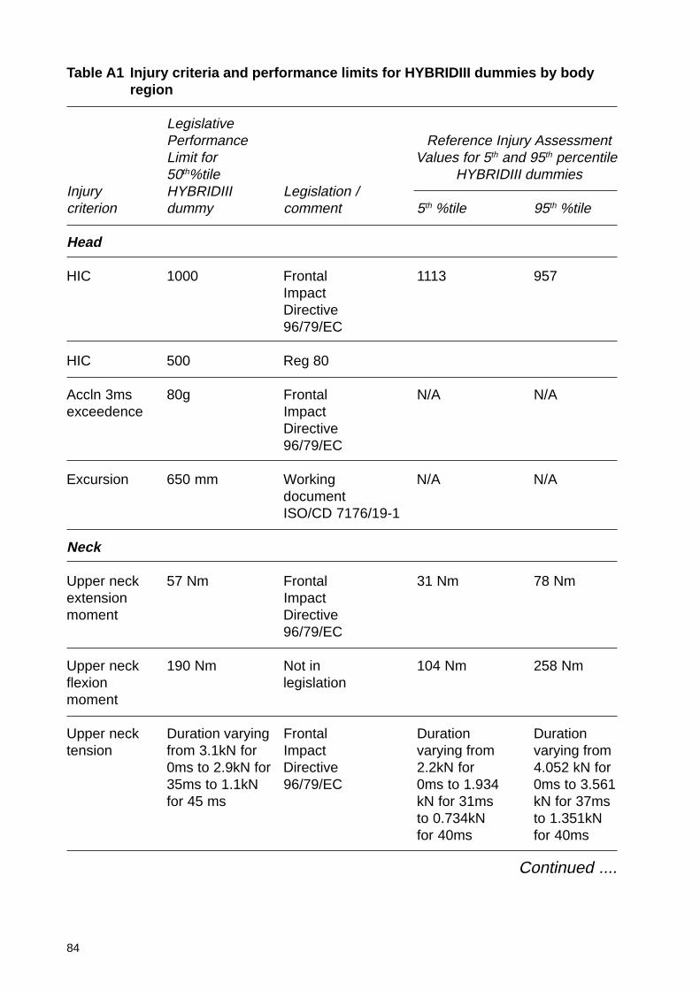
84
Table A1 Injury criteria and performance limits for HYBRIDIII dummies by bodyregion
LegislativePerformance Reference Injury AssessmentLimit for Values for 5th and 95th percentile50th%tile HYBRIDIII dummies
Injury HYBRIDIII Legislation /criterion dummy comment 5th %tile 95th %tile
Head
HIC 1000 Frontal 1113 957ImpactDirective96/79/EC
HIC 500 Reg 80
Accln 3ms 80g Frontal N/A N/Aexceedence Impact
Directive96/79/EC
Excursion 650 mm Working N/A N/AdocumentISO/CD 7176/19-1
Neck
Upper neck 57 Nm Frontal 31 Nm 78 Nmextension Impactmoment Directive
96/79/EC
Upper neck 190 Nm Not in 104 Nm 258 Nmflexion legislationmoment
Upper neck Duration varying Frontal Duration Durationtension from 3.1kN for Impact varying from varying from
0ms to 2.9kN for Directive 2.2kN for 4.052 kN for35ms to 1.1kN 96/79/EC 0ms to 1.934 0ms to 3.561for 45 ms kN for 31ms kN for 37ms
to 0.734kN to 1.351kNfor 40ms for 40ms
Continued ....
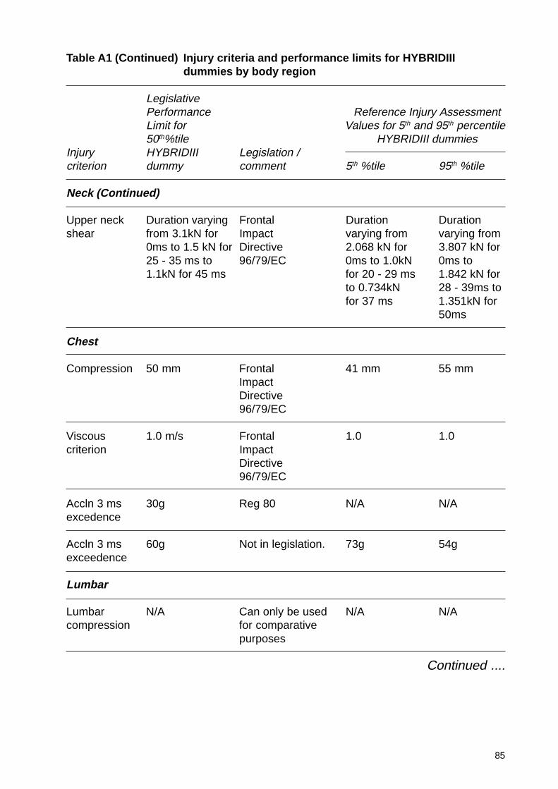
85
Table A1 (Continued) Injury criteria and performance limits for HYBRIDIIIdummies by body region
LegislativePerformance Reference Injury AssessmentLimit for Values for 5th and 95th percentile50th%tile HYBRIDIII dummies
Injury HYBRIDIII Legislation /criterion dummy comment 5th %tile 95th %tile
Neck (Continued)
Upper neck Duration varying Frontal Duration Durationshear from 3.1kN for Impact varying from varying from
0ms to 1.5 kN for Directive 2.068 kN for 3.807 kN for25 - 35 ms to 96/79/EC 0ms to 1.0kN 0ms to1.1kN for 45 ms for 20 - 29 ms 1.842 kN for
to 0.734kN 28 - 39ms tofor 37 ms 1.351kN for
50ms
Chest
Compression 50 mm Frontal 41 mm 55 mmImpactDirective96/79/EC
Viscous 1.0 m/s Frontal 1.0 1.0criterion Impact
Directive96/79/EC
Accln 3 ms 30g Reg 80 N/A N/Aexcedence
Accln 3 ms 60g Not in legislation. 73g 54gexceedence
Lumbar
Lumbar N/A Can only be used N/A N/Acompression for comparative
purposes
Continued ....
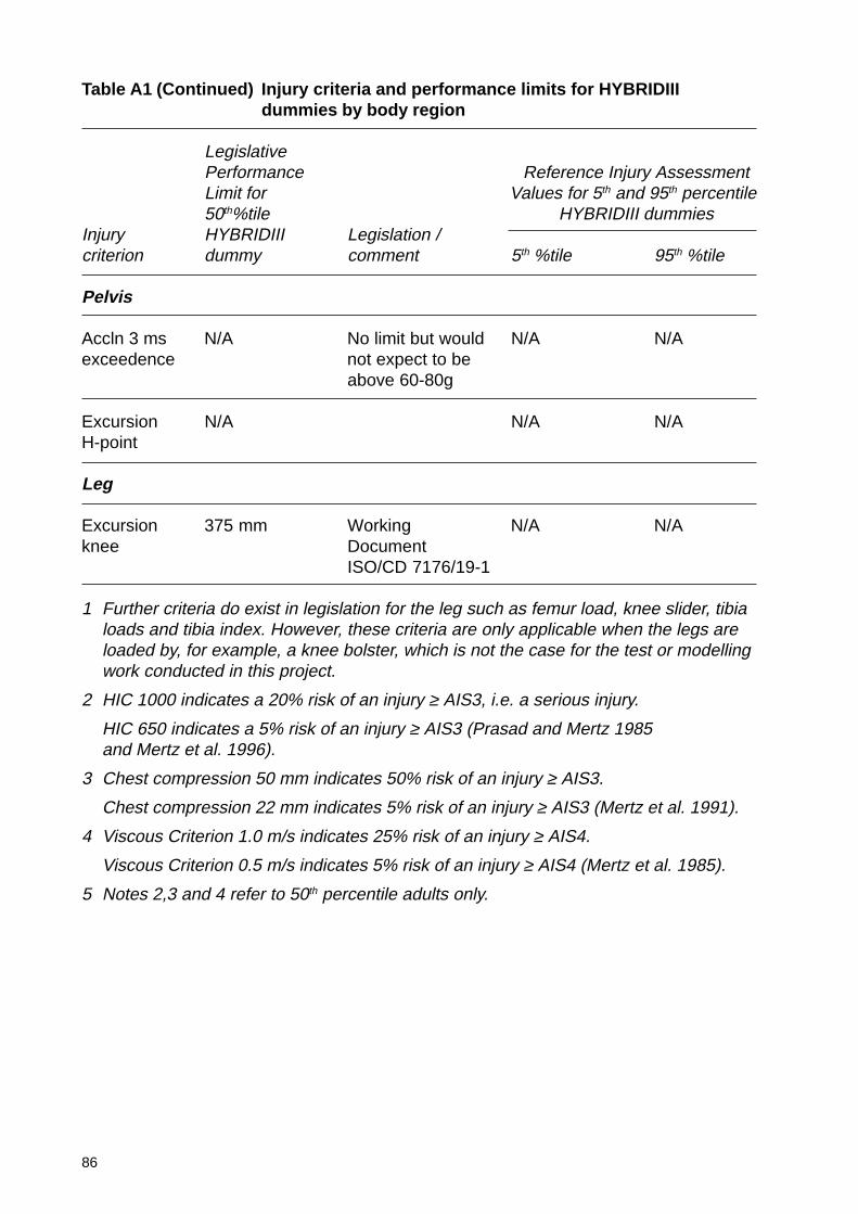
86
Table A1 (Continued) Injury criteria and performance limits for HYBRIDIIIdummies by body region
LegislativePerformance Reference Injury AssessmentLimit for Values for 5th and 95th percentile50th%tile HYBRIDIII dummies
Injury HYBRIDIII Legislation /criterion dummy comment 5th %tile 95th %tile
Pelvis
Accln 3 ms N/A No limit but would N/A N/Aexceedence not expect to be
above 60-80g
Excursion N/A N/A N/AH-point
Leg
Excursion 375 mm Working N/A N/Aknee Document
ISO/CD 7176/19-1
1 Further criteria do exist in legislation for the leg such as femur load, knee slider, tibialoads and tibia index. However, these criteria are only applicable when the legs areloaded by, for example, a knee bolster, which is not the case for the test or modellingwork conducted in this project.
2 HIC 1000 indicates a 20% risk of an injury ≥ AIS3, i.e. a serious injury.
HIC 650 indicates a 5% risk of an injury ≥ AIS3 (Prasad and Mertz 1985and Mertz et al. 1996).
3 Chest compression 50 mm indicates 50% risk of an injury ≥ AIS3.
Chest compression 22 mm indicates 5% risk of an injury ≥ AIS3 (Mertz et al. 1991).
4 Viscous Criterion 1.0 m/s indicates 25% risk of an injury ≥ AIS4.
Viscous Criterion 0.5 m/s indicates 5% risk of an injury ≥ AIS4 (Mertz et al. 1985).
5 Notes 2,3 and 4 refer to 50th percentile adults only.
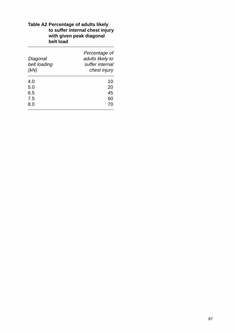
87
Table A2 Percentage of adults likelyto suffer internal chest injurywith given peak diagonalbelt load
Percentage ofDiagonal adults likely tobelt loading suffer internal(kN) chest injury
4.0 105.0 206.5 457.5 608.0 70
88
Appendix B: Test results
The following pages contain a full set of impact test results for each of the4 impact conditions investigated. The definition of each test is given in therelevant section of the main text.
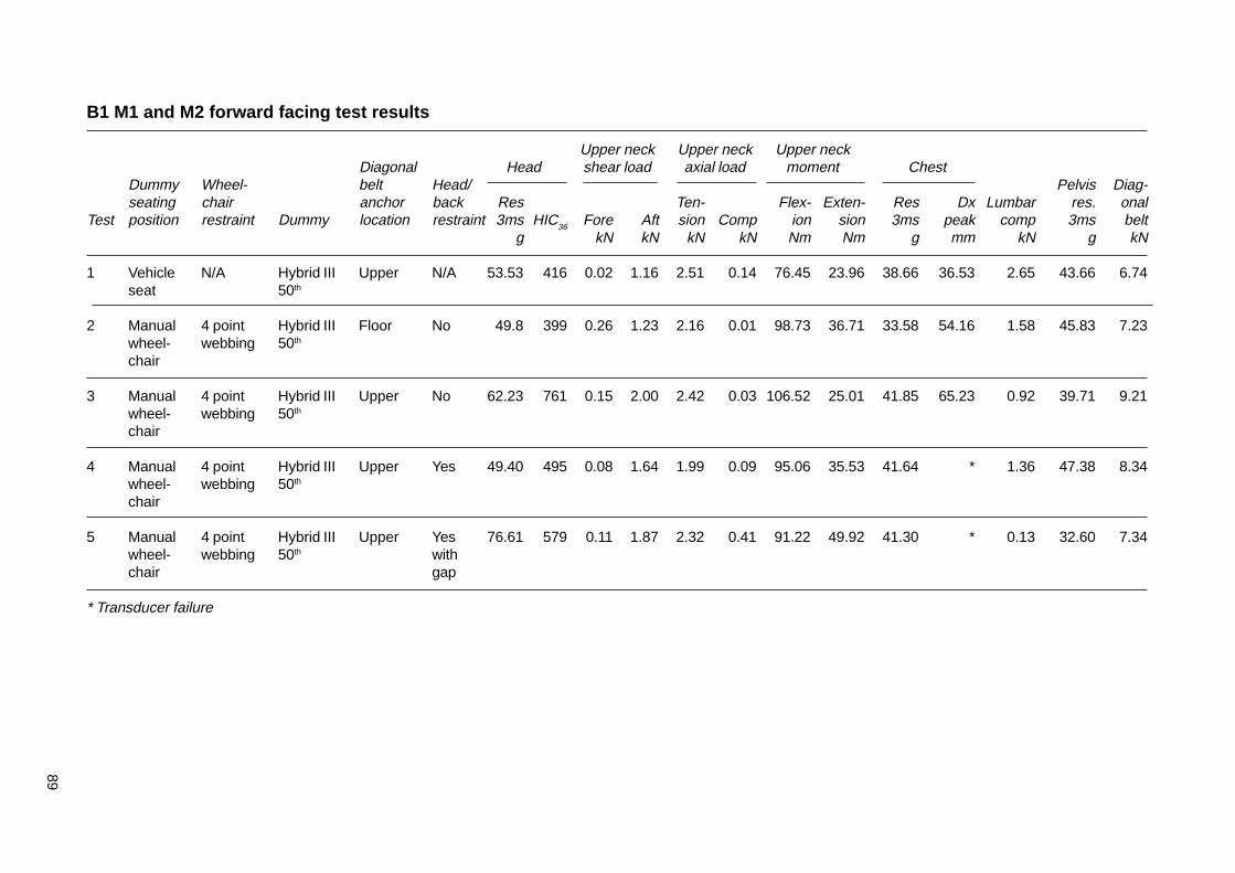
89
B1 M1 and M2 forward facing test results
Upper neck Upper neck Upper neckDiagonal Head shear load axial load moment Chest
Dummy Wheel- belt Head/ Pelvis Diag-seating chair anchor back Res Ten- Flex- Exten- Res Dx Lumbar res. onal
Test position restraint Dummy location restraint 3ms HIC36 Fore Aft sion Comp ion sion 3ms peak comp 3ms beltg kN kN kN kN Nm Nm g mm kN g kN
1 Vehicle N/A Hybrid III Upper N/A 53.53 416 0.02 1.16 2.51 0.14 76.45 23.96 38.66 36.53 2.65 43.66 6.74seat 50th
2 Manual 4 point Hybrid III Floor No 49.8 399 0.26 1.23 2.16 0.01 98.73 36.71 33.58 54.16 1.58 45.83 7.23wheel- webbing 50th
chair
3 Manual 4 point Hybrid III Upper No 62.23 761 0.15 2.00 2.42 0.03 106.52 25.01 41.85 65.23 0.92 39.71 9.21wheel- webbing 50th
chair
4 Manual 4 point Hybrid III Upper Yes 49.40 495 0.08 1.64 1.99 0.09 95.06 35.53 41.64 * 1.36 47.38 8.34wheel- webbing 50th
chair
5 Manual 4 point Hybrid III Upper Yes 76.61 579 0.11 1.87 2.32 0.41 91.22 49.92 41.30 * 0.13 32.60 7.34wheel- webbing 50th withchair gap
* Transducer failure
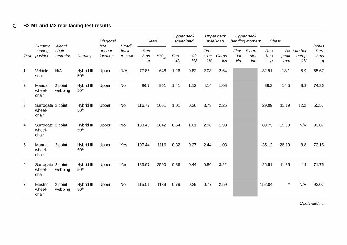
90 B2 M1 and M2 rear facing test results
Upper neck Upper neck Upper neckDiagonal Head shear load axial load bending moment Chest
Dummy Wheel- belt Head/ Pelvisseating chair anchor back Res Ten- Flex- Exten- Res Dx Lumbar Res.
Test position restraint Dummy location restraint 3ms HIC36 Fore Aft sion Comp ion sion 3ms peak comp 3msg kN kN kN kN Nm Nm g mm kN g
1 Vehicle N/A Hybrid III Upper N/A 77.86 648 1.26 0.82 2.08 2.64 32.91 18.1 5.9 65.67seat 50th
2 Manual 2 point Hybrid III Upper No 96.7 951 1.41 1.12 4.14 1.08 39.3 14.5 8.3 74.36wheel- webbing 50th
chair
3 Surrogate 2 point Hybrid III Upper No 116.77 1051 1.01 0.26 3.73 2.25 29.09 11.19 12.2 55.57wheel- 50th
chair
4 Surrogate 2 point Hybrid III Upper No 133.45 1842 0.64 1.01 2.96 1.98 89.73 15.99 N/A 93.07wheel- 50th
chair
5 Manual 2 point Hybrid III Upper Yes 107.44 1116 0.32 0.27 2.44 1.03 35.12 26.19 8.8 72.15wheel- 50th
chair
6 Surrogate 2 point Hybrid III Upper Yes 183.67 2590 0.86 0.44 0.86 3.22 26.51 11.85 14 71.75wheel- webbing 50th
chair
7 Electric 2 point Hybrid III Upper No 115.01 1139 0.79 0.29 0.77 2.59 152.04 * N/A 93.07wheel- webbing 50th
chair
Continued ....

91
B2 (Continued) M1 rear facing test results
Upper neck Upper neck Upper neckDiagonal Head shear load axial load bending moment Chest
Dummy Wheel- belt Head/ Pelvisseating chair anchor back Res Ten- Flex- Exten- Res Dx Lumbar Res.
Test position restraint Dummy location restraint 3ms HIC36 Fore Aft sion Comp ion sion 3ms peak comp 3msg kN kN kN kN Nm Nm g mm kN g
8 Manual 2 point Hybrid III Upper Yes 51.00 193.4 0.72 0.35 3.09 1.03 64.94 60.29 59.92 * 4.29 43.50wheel- webbing 50th
chair
9 Manual 2 point Hybrid III Upper With 110.3 1667 1.39 1.60 4.84 1.40 169.15 74.89 69.02 * 2.14 61.26wheel- webbing 50th gapchair
Tests 1 - 7 used LTi bodyshell
Tests 8 and 9 no bodyshell and modified Rescroft head and back restraint
* Transducer failureShaded areas denote channel not measured
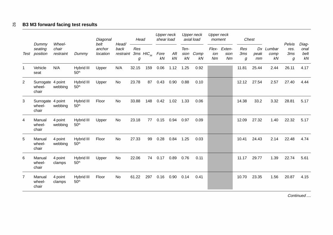
92 B3 M3 forward facing test results
Upper neck Upper neck Upper neckDiagonal Head shear load axial load moment Chest
Dummy Wheel- belt Head/ Pelvis Diag-seating chair anchor back Res Ten- Flex- Exten- Res Dx Lumbar res. onal
Test position restraint Dummy location restraint 3ms HIC36 Fore Aft sion Comp ion sion 3ms peak comp 3ms beltg kN kN kN kN Nm Nm g mm kN g kN
1 Vehicle N/A Hybrid III Upper N/A 32.15 159 0.06 1.12 1.25 0.92 11.81 25.44 2.44 26.11 4.17seat 50th
2 Surrogate 4 point Hybrid III Upper No 23.78 87 0.43 0.90 0.88 0.10 12.12 27.54 2.57 27.40 4.44wheel- webbing 50th
chair
3 Surrogate 4 point Hybrid III Floor No 33.88 148 0.42 1.02 1.33 0.06 14.38 33.2 3.32 28.81 5.17wheel- webbing 50th
chair
4 Manual 4 point Hybrid III Upper No 23.18 77 0.15 0.94 0.97 0.09 12.09 27.32 1.40 22.32 5.17wheel- webbing 50th
chair
5 Manual 4 point Hybrid III Floor No 27.33 99 0.28 0.84 1.25 0.03 10.41 24.43 2.14 22.48 4.74wheel- webbing 50th
chair
6 Manual 4 point Hybrid III Upper No 22.06 74 0.17 0.89 0.76 0.11 11.17 29.77 1.39 22.74 5.61wheel- clamps 50th
chair
7 Manual 4 point Hybrid III Floor No 61.22 297 0.16 0.90 0.14 0.41 10.70 23.35 1.56 20.87 4.15wheel- clamps 50th
chair
Continued ....
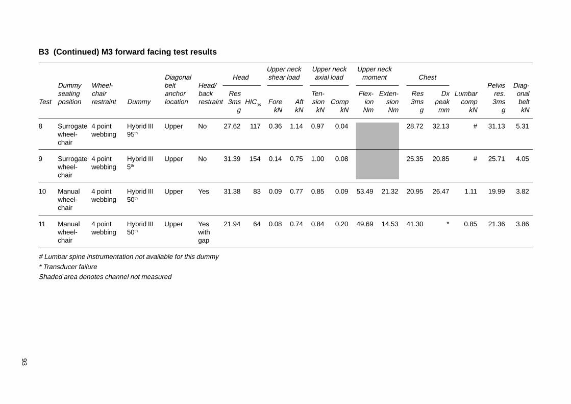
93
B3 (Continued) M3 forward facing test results
Upper neck Upper neck Upper neckDiagonal Head shear load axial load moment Chest
Dummy Wheel- belt Head/ Pelvis Diag-seating chair anchor back Res Ten- Flex- Exten- Res Dx Lumbar res. onal
Test position restraint Dummy location restraint 3ms HIC36 Fore Aft sion Comp ion sion 3ms peak comp 3ms beltg kN kN kN kN Nm Nm g mm kN g kN
8 Surrogate 4 point Hybrid III Upper No 27.62 117 0.36 1.14 0.97 0.04 28.72 32.13 # 31.13 5.31wheel- webbing 95th
chair
9 Surrogate 4 point Hybrid III Upper No 31.39 154 0.14 0.75 1.00 0.08 25.35 20.85 # 25.71 4.05wheel- webbing 5th
chair
10 Manual 4 point Hybrid III Upper Yes 31.38 83 0.09 0.77 0.85 0.09 53.49 21.32 20.95 26.47 1.11 19.99 3.82wheel- webbing 50th
chair
11 Manual 4 point Hybrid III Upper Yes 21.94 64 0.08 0.74 0.84 0.20 49.69 14.53 41.30 * 0.85 21.36 3.86wheel- webbing 50th withchair gap
# Lumbar spine instrumentation not available for this dummy
* Transducer failureShaded area denotes channel not measured
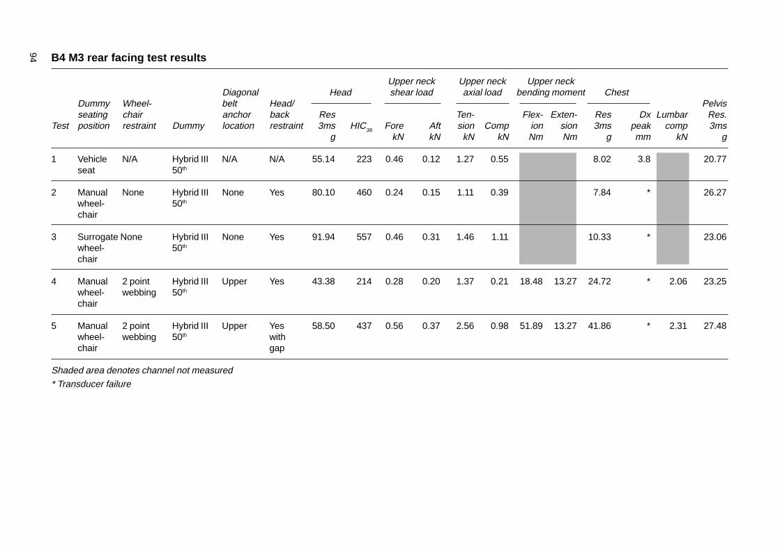
94 B4 M3 rear facing test results
Upper neck Upper neck Upper neckDiagonal Head shear load axial load bending moment Chest
Dummy Wheel- belt Head/ Pelvisseating chair anchor back Res Ten- Flex- Exten- Res Dx Lumbar Res.
Test position restraint Dummy location restraint 3ms HIC36 Fore Aft sion Comp ion sion 3ms peak comp 3msg kN kN kN kN Nm Nm g mm kN g
1 Vehicle N/A Hybrid III N/A N/A 55.14 223 0.46 0.12 1.27 0.55 8.02 3.8 20.77seat 50th
2 Manual None Hybrid III None Yes 80.10 460 0.24 0.15 1.11 0.39 7.84 * 26.27wheel- 50th
chair
3 Surrogate None Hybrid III None Yes 91.94 557 0.46 0.31 1.46 1.11 10.33 * 23.06wheel- 50th
chair
4 Manual 2 point Hybrid III Upper Yes 43.38 214 0.28 0.20 1.37 0.21 18.48 13.27 24.72 * 2.06 23.25wheel- webbing 50th
chair
5 Manual 2 point Hybrid III Upper Yes 58.50 437 0.56 0.37 2.56 0.98 51.89 13.27 41.86 * 2.31 27.48wheel- webbing 50th withchair gap
Shaded area denotes channel not measured* Transducer failure
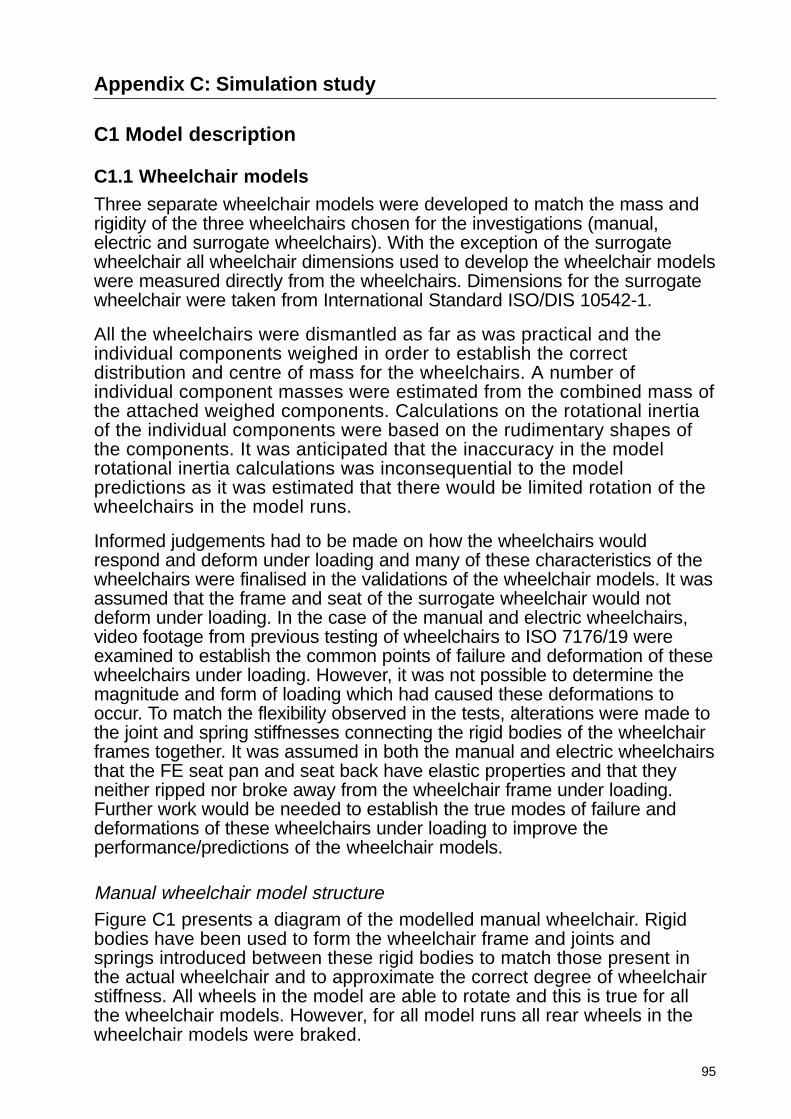
95
Appendix C: Simulation study
C1 Model description
C1.1 Wheelchair models
Three separate wheelchair models were developed to match the mass andrigidity of the three wheelchairs chosen for the investigations (manual,electric and surrogate wheelchairs). With the exception of the surrogatewheelchair all wheelchair dimensions used to develop the wheelchair modelswere measured directly from the wheelchairs. Dimensions for the surrogatewheelchair were taken from International Standard ISO/DIS 10542-1.
All the wheelchairs were dismantled as far as was practical and theindividual components weighed in order to establish the correctdistribution and centre of mass for the wheelchairs. A number ofindividual component masses were estimated from the combined mass ofthe attached weighed components. Calculations on the rotational inertiaof the individual components were based on the rudimentary shapes ofthe components. It was anticipated that the inaccuracy in the modelrotational inertia calculations was inconsequential to the modelpredictions as it was estimated that there would be limited rotation of thewheelchairs in the model runs.
Informed judgements had to be made on how the wheelchairs wouldrespond and deform under loading and many of these characteristics of thewheelchairs were finalised in the validations of the wheelchair models. It wasassumed that the frame and seat of the surrogate wheelchair would notdeform under loading. In the case of the manual and electric wheelchairs,video footage from previous testing of wheelchairs to ISO 7176/19 wereexamined to establish the common points of failure and deformation of thesewheelchairs under loading. However, it was not possible to determine themagnitude and form of loading which had caused these deformations tooccur. To match the flexibility observed in the tests, alterations were made tothe joint and spring stiffnesses connecting the rigid bodies of the wheelchairframes together. It was assumed in both the manual and electric wheelchairsthat the FE seat pan and seat back have elastic properties and that theyneither ripped nor broke away from the wheelchair frame under loading.Further work would be needed to establish the true modes of failure anddeformations of these wheelchairs under loading to improve theperformance/predictions of the wheelchair models.
Manual wheelchair model structureFigure C1 presents a diagram of the modelled manual wheelchair. Rigidbodies have been used to form the wheelchair frame and joints andsprings introduced between these rigid bodies to match those present inthe actual wheelchair and to approximate the correct degree of wheelchairstiffness. All wheels in the model are able to rotate and this is true for allthe wheelchair models. However, for all model runs all rear wheels in thewheelchair models were braked.
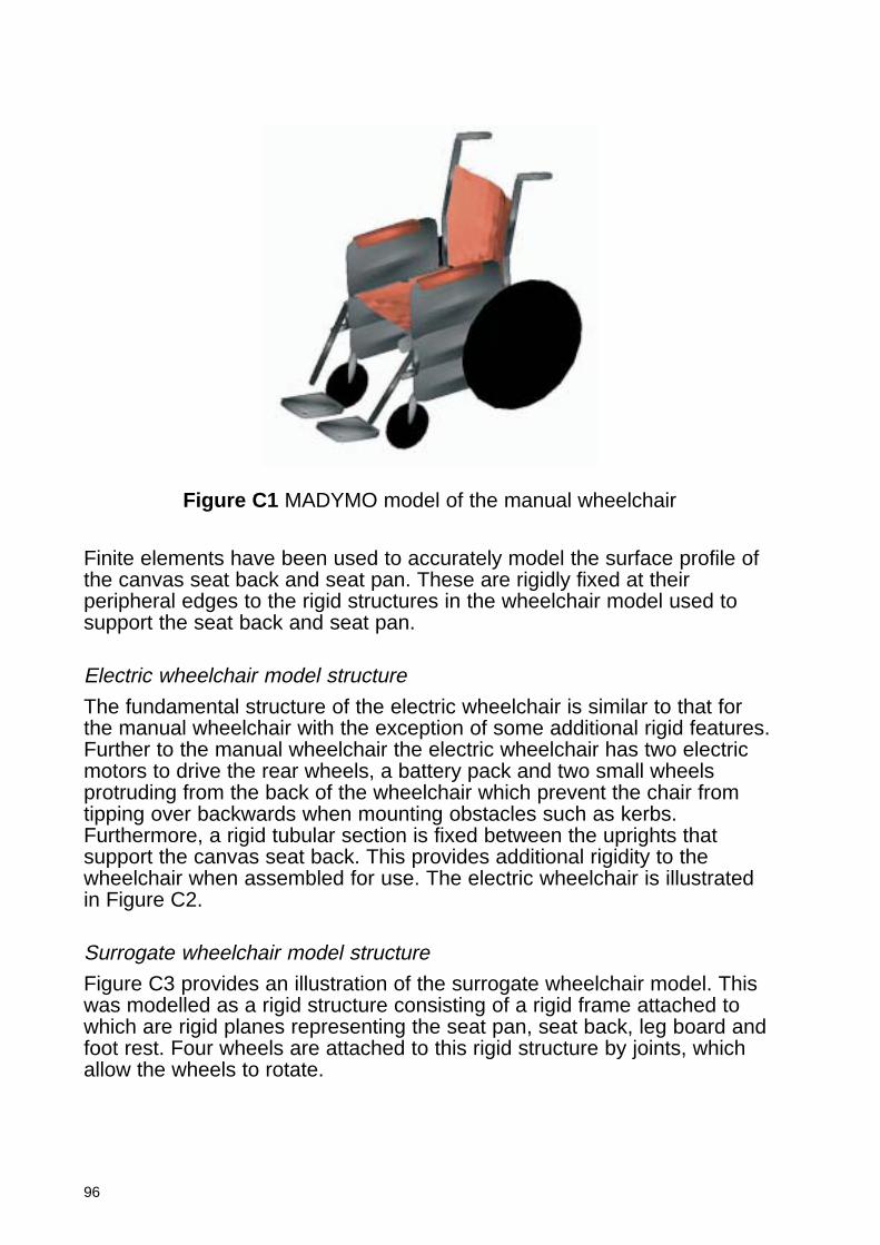
96
Finite elements have been used to accurately model the surface profile ofthe canvas seat back and seat pan. These are rigidly fixed at theirperipheral edges to the rigid structures in the wheelchair model used tosupport the seat back and seat pan.
Electric wheelchair model structure
The fundamental structure of the electric wheelchair is similar to that forthe manual wheelchair with the exception of some additional rigid features.Further to the manual wheelchair the electric wheelchair has two electricmotors to drive the rear wheels, a battery pack and two small wheelsprotruding from the back of the wheelchair which prevent the chair fromtipping over backwards when mounting obstacles such as kerbs.Furthermore, a rigid tubular section is fixed between the uprights thatsupport the canvas seat back. This provides additional rigidity to thewheelchair when assembled for use. The electric wheelchair is illustratedin Figure C2.
Surrogate wheelchair model structure
Figure C3 provides an illustration of the surrogate wheelchair model. Thiswas modelled as a rigid structure consisting of a rigid frame attached towhich are rigid planes representing the seat pan, seat back, leg board andfoot rest. Four wheels are attached to this rigid structure by joints, whichallow the wheels to rotate.
Figure C1 MADYMO model of the manual wheelchair
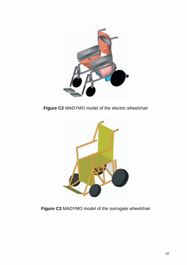
97
Figure C2 MADYMO model of the electric wheelchair
Figure C3 MADYMO model of the surrogate wheelchair
98
C1.2 Dummy models
The MADYMO software is supplied with a family of validated Hybrid IIIdummy models (5th, 50th and 95th percentile). For the purposes of thismodelling study, it was necessary to position these dummies in the modelledwheelchairs and also to fit the occupant restraints over the dummies.
Further to the family of Hybrid III dummy models, a 50th percentile humanbody model has recently been developed in MADYMO, which provides amore human-like biofidelic response than the Hybrid III dummy model. Itwould have been possible to use the human body model in this modellingstudy. However, use of the 50th percentile human body model would haveprevented model predictions being compared directly with test results andwould have invalidated the use of the injury criteria outlined in Appendix 1to interpret model predictions. However, this is a useful reference for anyfuture modelling studies requiring a more biofidelic human body model.
C1.3 Vehicle interiors
Rear facing taxi and bus interiors were developed for the modelling studies.
Measurements were taken directly from a purpose built taxi interior todevelop the rear facing taxi interior model and establish the location of thewheelchair restraint and occupant tie-down points within the taxi.
The details of the modelled bus interior were taken from EC Directive2001/85 and the dimensions of the wheelchair back restraint used in thebus were measured directly from a back restraint conforming to the PublicService Vehicles Accessibility Regulations (2000). These regulations donot require either the occupant or wheelchair to be restrained in thedesignated wheelchair space on large buses and so the model replicatedthis situation.
No interior models were developed for the forward facing M1 situation asno taxis have this arrangement. However, in order to give some idea of thepossible confines of a forward facing M1 vehicle, a converted forwardfacing MPV (modified for personal use) was measured and the vehicledimensions were used as boundary thresholds against which the dummyexcursions were compared. Interior models were also not provided for M3coaches as it was assumed that interaction with the vehicle interior wouldnot occur in this type of vehicle.
The location of the tie-down points for the three point occupant restraints inthe forward facing M1 vehicle and M3 coach were initially taken from theconverted MPV. These were located behind and positioned laterally widerthan the width of the wheelchair in order to allow access for the wheelchairoccupant from the rear of the vehicle. However, this set-up did causeproblems in the model runs in which the shoulder strap of the occupantrestraint was attached to the floor. It was noticed in these model runs thatthe dummy failed to return back into the wheelchair seat following theimpact. However, the results from an almost identical test conducted atMillbrook revealed that the dummy did return back into the seat following
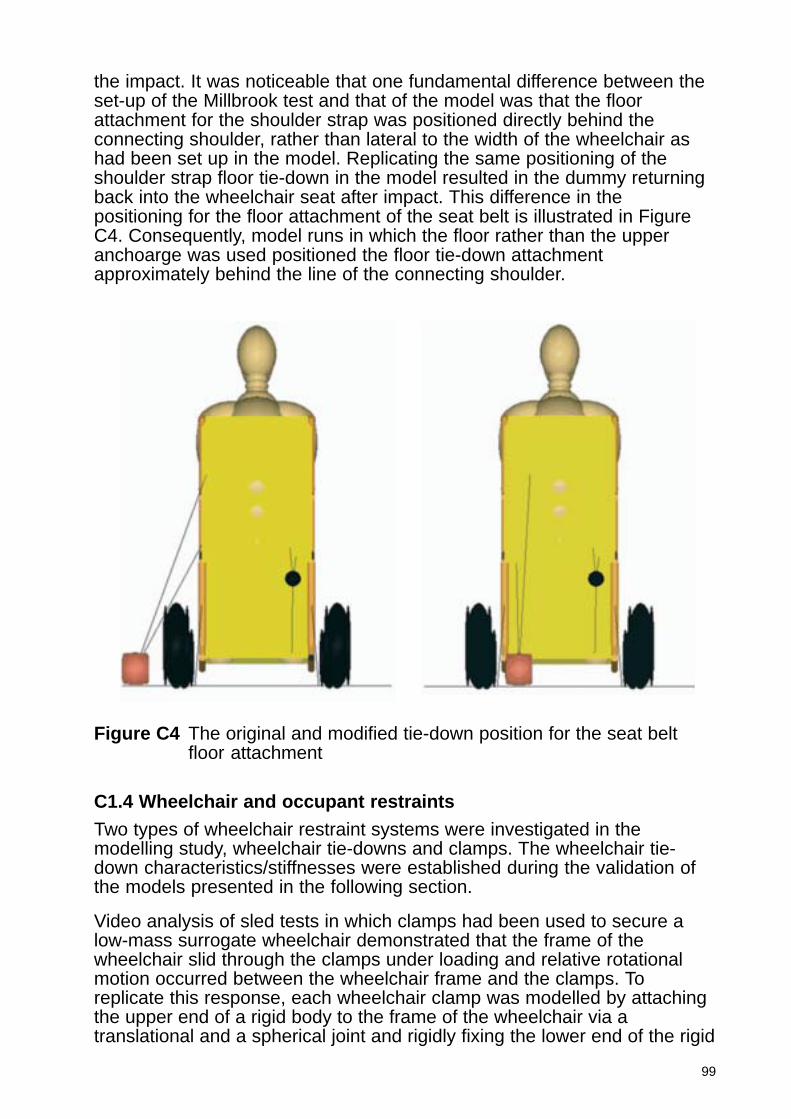
99
the impact. It was noticeable that one fundamental difference between theset-up of the Millbrook test and that of the model was that the floorattachment for the shoulder strap was positioned directly behind theconnecting shoulder, rather than lateral to the width of the wheelchair ashad been set up in the model. Replicating the same positioning of theshoulder strap floor tie-down in the model resulted in the dummy returningback into the wheelchair seat after impact. This difference in thepositioning for the floor attachment of the seat belt is illustrated in FigureC4. Consequently, model runs in which the floor rather than the upperanchoarge was used positioned the floor tie-down attachmentapproximately behind the line of the connecting shoulder.
C1.4 Wheelchair and occupant restraints
Two types of wheelchair restraint systems were investigated in themodelling study, wheelchair tie-downs and clamps. The wheelchair tie-down characteristics/stiffnesses were established during the validation ofthe models presented in the following section.
Video analysis of sled tests in which clamps had been used to secure alow-mass surrogate wheelchair demonstrated that the frame of thewheelchair slid through the clamps under loading and relative rotationalmotion occurred between the wheelchair frame and the clamps. Toreplicate this response, each wheelchair clamp was modelled by attachingthe upper end of a rigid body to the frame of the wheelchair via atranslational and a spherical joint and rigidly fixing the lower end of the rigid
Figure C4 The original and modified tie-down position for the seat beltfloor attachment
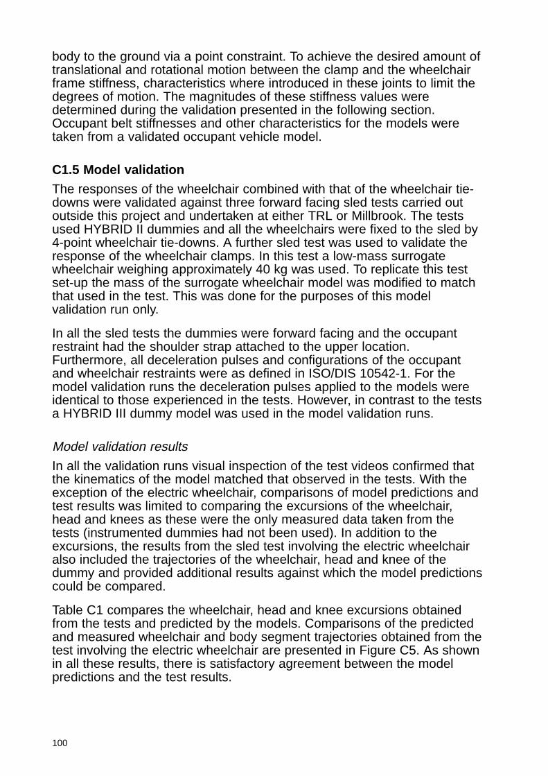
100
body to the ground via a point constraint. To achieve the desired amount oftranslational and rotational motion between the clamp and the wheelchairframe stiffness, characteristics where introduced in these joints to limit thedegrees of motion. The magnitudes of these stiffness values weredetermined during the validation presented in the following section.Occupant belt stiffnesses and other characteristics for the models weretaken from a validated occupant vehicle model.
C1.5 Model validation
The responses of the wheelchair combined with that of the wheelchair tie-downs were validated against three forward facing sled tests carried outoutside this project and undertaken at either TRL or Millbrook. The testsused HYBRID II dummies and all the wheelchairs were fixed to the sled by4-point wheelchair tie-downs. A further sled test was used to validate theresponse of the wheelchair clamps. In this test a low-mass surrogatewheelchair weighing approximately 40 kg was used. To replicate this testset-up the mass of the surrogate wheelchair model was modified to matchthat used in the test. This was done for the purposes of this modelvalidation run only.
In all the sled tests the dummies were forward facing and the occupantrestraint had the shoulder strap attached to the upper location.Furthermore, all deceleration pulses and configurations of the occupantand wheelchair restraints were as defined in ISO/DIS 10542-1. For themodel validation runs the deceleration pulses applied to the models wereidentical to those experienced in the tests. However, in contrast to the testsa HYBRID III dummy model was used in the model validation runs.
Model validation results
In all the validation runs visual inspection of the test videos confirmed thatthe kinematics of the model matched that observed in the tests. With theexception of the electric wheelchair, comparisons of model predictions andtest results was limited to comparing the excursions of the wheelchair,head and knees as these were the only measured data taken from thetests (instrumented dummies had not been used). In addition to theexcursions, the results from the sled test involving the electric wheelchairalso included the trajectories of the wheelchair, head and knee of thedummy and provided additional results against which the model predictionscould be compared.
Table C1 compares the wheelchair, head and knee excursions obtainedfrom the tests and predicted by the models. Comparisons of the predictedand measured wheelchair and body segment trajectories obtained from thetest involving the electric wheelchair are presented in Figure C5. As shownin all these results, there is satisfactory agreement between the modelpredictions and the test results.
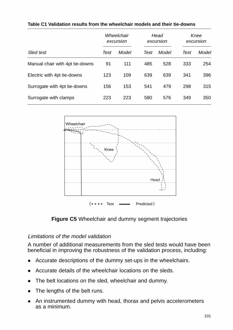
101
Table C1 Validation results from the wheelchair models and their tie-downs
Wheelchair Head Kneeexcursion excursion excursion
Sled test Test Model Test Model Test Model
Manual chair with 4pt tie-downs 91 111 485 528 333 254
Electric with 4pt tie-downs 123 109 639 639 341 396
Surrogate with 4pt tie-downs 156 153 541 479 298 315
Surrogate with clamps 223 223 580 576 349 350
Figure C5 Wheelchair and dummy segment trajectories
Knee
Wheelchair
Head
( Test Predicted )
Limitations of the model validation
A number of additional measurements from the sled tests would have beenbeneficial in improving the robustness of the validation process, including:
� Accurate descriptions of the dummy set-ups in the wheelchairs.
� Accurate details of the wheelchair locations on the sleds.
� The belt locations on the sled, wheelchair and dummy.
� The lengths of the belt runs.
� An instrumented dummy with head, thorax and pelvis accelerometersas a minimum.
102
The model validation has also been limited to testing the whole wheelchairand its tie-downs as one complete system. Additional benefits would havebeen achieved if components of the wheelchair such as the wheels andtyres, the wheelchair tie-downs and the occupant restraint systems werecharacterised individually in loading tests so that these could berepresented more accurately in the complete model. As a consequence ofthese limitations, model predictions can only be relied upon to providequalitative rather than quantitative interpretations of the expected outcomeof vehicle accidents.
C2 M1 modelling results
Thirty four model runs were completed investigating the outcome ofwheelchair users in taxi and minibus accidents. Within this number therewere two fundamental groups of transported wheelchair occupants toinvestigate; rearward facing and forward facing exposed to a R44 pulse.
C2.1 Rearward facing taxi
Methodology
Figure C6 shows the wheelchair and 50th percentile HYBRIDIII dummyoccupant located in the taxi. It was anticipated that the glass partitionpositioned behind the passenger’s head would break during the impact andthis fact was later confirmed in the dynamic tests. However, for thepurposes of the modelling it was assumed that the glass remained intact inorder to ensure that the wheelchair and occupant kinematics wererepresentative of a bulkhead in which the glass partition was mountedhigher and hence would not break. The wheelchairs were anchored to thetaxi bulkhead by a single strip of belt material, which split to connect to theleft and right rear sides of the wheelchair frame. Standard belt propertieswere used for this restraint.
For this rear facing configuration 12 model runs were made, all using theR44 deceleration pulse, modelling pulse 1, shown in Figure 1. The firstthree of these investigated the different response of each wheelchair,manual, electric and surrogate. The other runs were completed toinvestigate how the introduction and change in position and design of ahead and back restraint might help in reducing injuries. Three designs ofhead and back restraint were investigated in conjunction with eachwheelchair design. The head and back restraint designs were:
i A head and back restraint matching the shape and position of thatdefined in ECE Regulation 17 and rigidly fixed adjacent to the bulkheadfascia of the taxi.
ii A head and back restraint in which the back restraint is located at thesame position as that in (i), but the head restraint is positionedapproximately 90 mm closer to the occupant’s head than that in (i).
iii A head restraint only, located in the same position as that defined in (i)
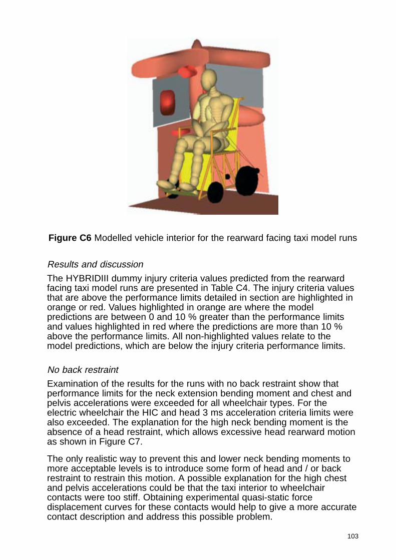
103
Figure C6 Modelled vehicle interior for the rearward facing taxi model runs
Results and discussion
The HYBRIDIII dummy injury criteria values predicted from the rearwardfacing taxi model runs are presented in Table C4. The injury criteria valuesthat are above the performance limits detailed in section are highlighted inorange or red. Values highlighted in orange are where the modelpredictions are between 0 and 10 % greater than the performance limitsand values highlighted in red where the predictions are more than 10 %above the performance limits. All non-highlighted values relate to themodel predictions, which are below the injury criteria performance limits.
No back restraint
Examination of the results for the runs with no back restraint show thatperformance limits for the neck extension bending moment and chest andpelvis accelerations were exceeded for all wheelchair types. For theelectric wheelchair the HIC and head 3 ms acceleration criteria limits werealso exceeded. The explanation for the high neck bending moment is theabsence of a head restraint, which allows excessive head rearward motionas shown in Figure C7.
The only realistic way to prevent this and lower neck bending moments tomore acceptable levels is to introduce some form of head and / or backrestraint to restrain this motion. A possible explanation for the high chestand pelvis accelerations could be that the taxi interior to wheelchaircontacts were too stiff. Obtaining experimental quasi-static forcedisplacement curves for these contacts would help to give a more accuratecontact description and address this possible problem.
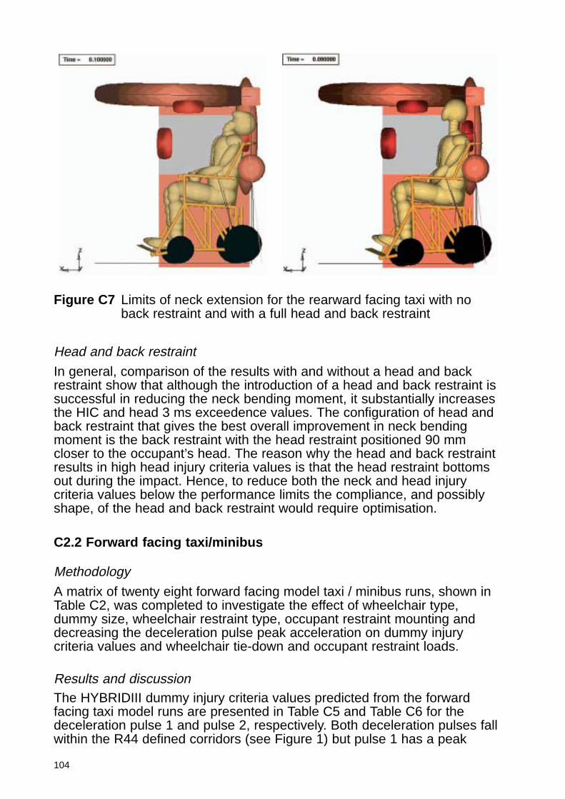
104
Head and back restraint
In general, comparison of the results with and without a head and backrestraint show that although the introduction of a head and back restraint issuccessful in reducing the neck bending moment, it substantially increasesthe HIC and head 3 ms exceedence values. The configuration of head andback restraint that gives the best overall improvement in neck bendingmoment is the back restraint with the head restraint positioned 90 mmcloser to the occupant’s head. The reason why the head and back restraintresults in high head injury criteria values is that the head restraint bottomsout during the impact. Hence, to reduce both the neck and head injurycriteria values below the performance limits the compliance, and possiblyshape, of the head and back restraint would require optimisation.
C2.2 Forward facing taxi/minibus
Methodology
A matrix of twenty eight forward facing model taxi / minibus runs, shown inTable C2, was completed to investigate the effect of wheelchair type,dummy size, wheelchair restraint type, occupant restraint mounting anddecreasing the deceleration pulse peak acceleration on dummy injurycriteria values and wheelchair tie-down and occupant restraint loads.
Results and discussionThe HYBRIDIII dummy injury criteria values predicted from the forwardfacing taxi model runs are presented in Table C5 and Table C6 for thedeceleration pulse 1 and pulse 2, respectively. Both deceleration pulses fallwithin the R44 defined corridors (see Figure 1) but pulse 1 has a peak
Figure C7 Limits of neck extension for the rearward facing taxi with noback restraint and with a full head and back restraint
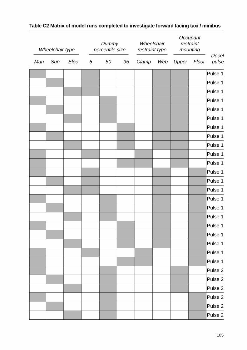
105
Table C2 Matrix of model runs completed to investigate forward facing taxi / minibus
OccupantDummy Wheelchair restraint
Wheelchair type percentile size restraint type mountingDecel
Man Surr Elec 5 50 95 Clamp Web Upper Floor pulse
Pulse 1
Pulse 1
Pulse 1
Pulse 1
Pulse 1
Pulse 1
Pulse 1
Pulse 1
Pulse 1
Pulse 1
Pulse 1
Pulse 1
Pulse 1
Pulse 1
Pulse 1
Pulse 1
Pulse 1
Pulse 1
Pulse 1
Pulse 1
Pulse 1
Pulse 1
Pulse 2
Pulse 2
Pulse 2
Pulse 2
Pulse 2
Pulse 2
106
acceleration of approximately 20g whereas pulse 2 has a peakacceleration of approximately 25g. The injury criteria values that are abovethe performance limits detailed in Section 0 are highlighted in orange orred as for the rearward facing taxi runs. Wheelchair tie-down and occupantrestraint loads and lumbar spine loads are shown in Table C7 and TableC8, for deceleration pulses 1 and 2, respectively.
Upper / floor mounted occupant restraint
There are two basic types of wheelchair occupant restraint, one inwhich the belt is routed through an upper location and the other inwhich no upper location is present and the belt is routed directly fromthe floor to the wheelchair occupant’s shoulder. This latter type isreferred to as ‘floor mounted’.
If the data in Table C5 are examined it is clearly seen that, in general, thehead and neck injury criteria values for the are far higher for the floormounted compared to the upper mounted restraint. In addition, far moreinjury criteria performance limits are exceeded for the floor mountedrestraint. The reason for this is that the floor mounted restraint does notadequately restrain the occupant’s upper body and allows it to rotate aboutthe waist leading to the head impacting the knees as shown in Figure C8.This also explains why the chest injury criteria were lower for the floormounted restraint. The upper and lower lumbar spine load cellcompression values recorded are shown in Table C7. Examination of themshows that the lumbar compression is far higher for the floor mountedcompared to upper mounted restraint. This indicates a higher likelihood oflumbar spine injury for the floor mounted restraint. However, this cannot bequantified, as there are no injury criteria for the lumbar spine.
Wheelchair type
There is no significant difference in the injury criteria predicted for thedifferent wheelchair types (Table C5). However, in general, the surrogatewheelchair gives the lowest injury criteria values. This could be due to itshigher mass resulting in greater forward motion in the impact leading to anincreased ride down distance for the occupant.
Tie-downs / clamps
The model runs in which clamps were used to fix the wheelchair in positionresult in approximately similar injury criteria predictions to the equivalentruns completed with tie-downs used to fix the wheelchair to the taxi floor(Table C5). However, the wheelchair does move substantially furtherforward when restrained by clamps, about 200 mm for clamps compared to50 mm for tie-downs. The peak loads sustained by each clamp for thesemodel runs were between 7.3 and 12.4 kN with the higher loads coincidentwith the use of the 95 % dummy (Table C7)
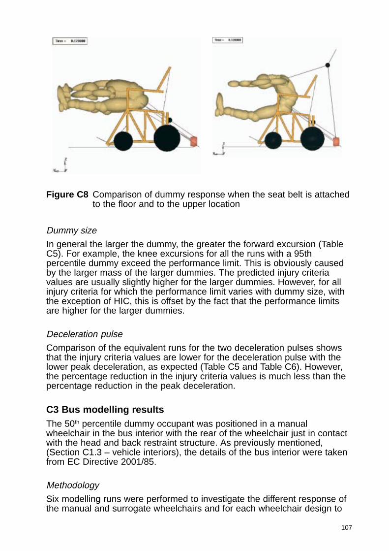
107
Dummy size
In general the larger the dummy, the greater the forward excursion (TableC5). For example, the knee excursions for all the runs with a 95thpercentile dummy exceed the performance limit. This is obviously causedby the larger mass of the larger dummies. The predicted injury criteriavalues are usually slightly higher for the larger dummies. However, for allinjury criteria for which the performance limit varies with dummy size, withthe exception of HIC, this is offset by the fact that the performance limitsare higher for the larger dummies.
Deceleration pulse
Comparison of the equivalent runs for the two deceleration pulses showsthat the injury criteria values are lower for the deceleration pulse with thelower peak deceleration, as expected (Table C5 and Table C6). However,the percentage reduction in the injury criteria values is much less than thepercentage reduction in the peak deceleration.
C3 Bus modelling resultsThe 50th percentile dummy occupant was positioned in a manualwheelchair in the bus interior with the rear of the wheelchair just in contactwith the head and back restraint structure. As previously mentioned,(Section C1.3 – vehicle interiors), the details of the bus interior were takenfrom EC Directive 2001/85.
Methodology
Six modelling runs were performed to investigate the different response ofthe manual and surrogate wheelchairs and for each wheelchair design to
Figure C8 Comparison of dummy response when the seat belt is attachedto the floor and to the upper location
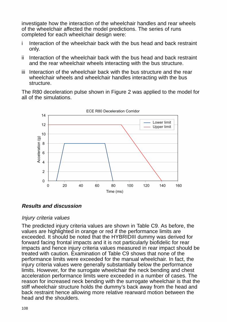
108
investigate how the interaction of the wheelchair handles and rear wheelsof the wheelchair affected the model predictions. The series of runscompleted for each wheelchair design were:
i Interaction of the wheelchair back with the bus head and back restraintonly.
ii Interaction of the wheelchair back with the bus head and back restraintand the rear wheelchair wheels interacting with the bus structure.
iii Interaction of the wheelchair back with the bus structure and the rearwheelchair wheels and wheelchair handles interacting with the busstructure.
The R80 deceleration pulse shown in Figure 2 was applied to the model forall of the simulations.
ECE R80 Deceleration Corridor
0
2
4
6
8
10
12
14
0 20 40 60 80 100 120 140 160
Time (ms)
Accele
ration (
g)
Lower limitUpper limit
Results and discussion
Injury criteria values
The predicted injury criteria values are shown in Table C9. As before, thevalues are highlighted in orange or red if the performance limits areexceeded. It should be noted that the HYBRIDIII dummy was derived forforward facing frontal impacts and it is not particularly biofidelic for rearimpacts and hence injury criteria values measured in rear impact should betreated with caution. Examination of Table C9 shows that none of theperformance limits were exceeded for the manual wheelchair. In fact, theinjury criteria values were generally substantially below the performancelimits. However, for the surrogate wheelchair the neck bending and chestacceleration performance limits were exceeded in a number of cases. Thereason for increased neck bending with the surrogate wheelchair is that thestiff wheelchair structure holds the dummy’s back away from the head andback restraint hence allowing more relative rearward motion between thehead and the shoulders.
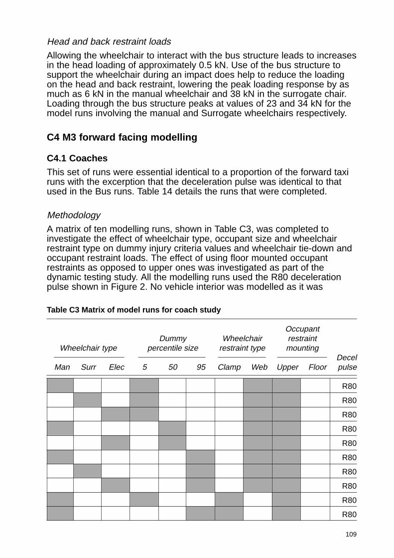
109
Head and back restraint loads
Allowing the wheelchair to interact with the bus structure leads to increasesin the head loading of approximately 0.5 kN. Use of the bus structure tosupport the wheelchair during an impact does help to reduce the loadingon the head and back restraint, lowering the peak loading response by asmuch as 6 kN in the manual wheelchair and 38 kN in the surrogate chair.Loading through the bus structure peaks at values of 23 and 34 kN for themodel runs involving the manual and Surrogate wheelchairs respectively.
C4 M3 forward facing modelling
C4.1 Coaches
This set of runs were essential identical to a proportion of the forward taxiruns with the excerption that the deceleration pulse was identical to thatused in the Bus runs. Table 14 details the runs that were completed.
Methodology
A matrix of ten modelling runs, shown in Table C3, was completed toinvestigate the effect of wheelchair type, occupant size and wheelchairrestraint type on dummy injury criteria values and wheelchair tie-down andoccupant restraint loads. The effect of using floor mounted occupantrestraints as opposed to upper ones was investigated as part of thedynamic testing study. All the modelling runs used the R80 decelerationpulse shown in Figure 2. No vehicle interior was modelled as it was
Table C3 Matrix of model runs for coach study
OccupantDummy Wheelchair restraint
Wheelchair type percentile size restraint type mountingDecel
Man Surr Elec 5 50 95 Clamp Web Upper Floor pulse
R80
R80
R80
R80
R80
R80
R80
R80
R80
R80
110
assumed that the dummy would not interact with the interior. However,excursion measurements were taken.
Results and discussion
Injury criteria predictions
As shown in Table C10 there was only one instance in which the injurycriteria predicted by the coach models exceeded the performance limit, butby less than 3 percent. In general the injury criteria values weresubstantially below the performance limits indicating a low likelihood ofserious injury for this type of impact.
Tie-downs / clamps
Comparison of the predicted injury criteria values for the equivalent runsfor wheelchair tie-downs and clamps show no little difference and henceindicate that clamps are as effective as tie-downs in constraining themanual wheelchair in this type of impact.
Table C11 shows that wheelchair clamps were required to support loadsapproximately 1 kN to 2 kN greater than the rear wheelchair tie-downs inthe equivalent model runs for the 5 and 95 occupant dummies,respectively.
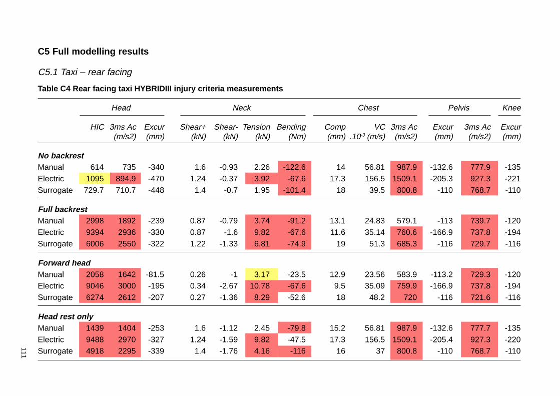
111
Table C4 Rear facing taxi HYBRIDIII injury criteria measurements
Head Neck Chest Pelvis Knee
HIC 3ms Ac Excur Shear+ Shear- Tension Bending Comp VC 3ms Ac Excur 3ms Ac Excur(m/s2) (mm) (kN) (kN) (kN) (Nm) (mm) .10-3 (m/s) (m/s2) (mm) (m/s2) (mm)
No backrestManual 614 735 -340 1.6 -0.93 2.26 -122.6 14 56.81 987.9 -132.6 777.9 -135Electric 1095 894.9 -470 1.24 -0.37 3.92 -67.6 17.3 156.5 1509.1 -205.3 927.3 -221Surrogate 729.7 710.7 -448 1.4 -0.7 1.95 -101.4 18 39.5 800.8 -110 768.7 -110
Full backrestManual 2998 1892 -239 0.87 -0.79 3.74 -91.2 13.1 24.83 579.1 -113 739.7 -120Electric 9394 2936 -330 0.87 -1.6 9.82 -67.6 11.6 35.14 760.6 -166.9 737.8 -194Surrogate 6006 2550 -322 1.22 -1.33 6.81 -74.9 19 51.3 685.3 -116 729.7 -116
Forward headManual 2058 1642 -81.5 0.26 -1 3.17 -23.5 12.9 23.56 583.9 -113.2 729.3 -120Electric 9046 3000 -195 0.34 -2.67 10.78 -67.6 9.5 35.09 759.9 -166.9 737.8 -194Surrogate 6274 2612 -207 0.27 -1.36 8.29 -52.6 18 48.2 720 -116 721.6 -116
Head rest onlyManual 1439 1404 -253 1.6 -1.12 2.45 -79.8 15.2 56.81 987.9 -132.6 777.7 -135Electric 9488 2970 -327 1.24 -1.59 9.82 -47.5 17.3 156.5 1509.1 -205.4 927.3 -220Surrogate 4918 2295 -339 1.4 -1.76 4.16 -116 16 37 800.8 -110 768.7 -110
C5 Full modelling results
C5.1 Taxi – rear facing
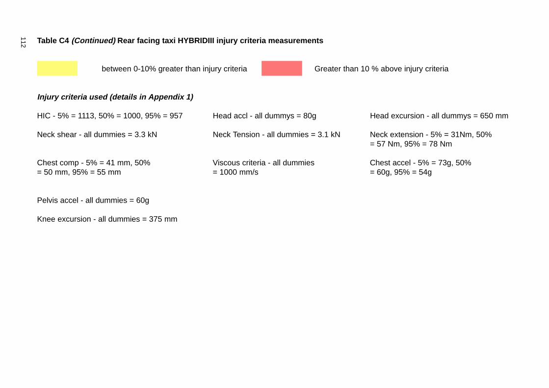
112 Table C4 (Continued) Rear facing taxi HYBRIDIII injury criteria measurements
between 0-10% greater than injury criteria Greater than 10 % above injury criteria
Injury criteria used (details in Appendix 1)
HIC - 5% = 1113, 50% = 1000, 95% = 957 Head accl - all dummys = 80g Head excursion - all dummys = 650 mm
Neck shear - all dummies = 3.3 kN Neck Tension - all dummies = 3.1 kN Neck extension - 5% = 31Nm, 50%= 57 Nm, 95% = 78 Nm
Chest comp - 5% = 41 mm, 50% Viscous criteria - all dummies Chest accel - 5% = 73g, 50%= 50 mm, 95% = 55 mm = 1000 mm/s = 60g, 95% = 54g
Pelvis accel - all dummies = 60g
Knee excursion - all dummies = 375 mm
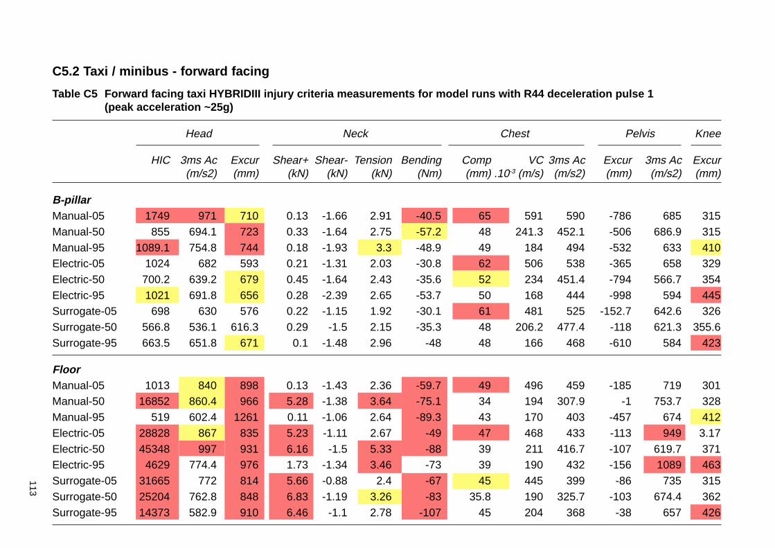
113
C5.2 Taxi / minibus - forward facing
Table C5 Forward facing taxi HYBRIDIII injury criteria measurements for model runs with R44 deceleration pulse 1(peak acceleration ~25g)
Head Neck Chest Pelvis Knee
HIC 3ms Ac Excur Shear+ Shear- Tension Bending Comp VC 3ms Ac Excur 3ms Ac Excur(m/s2) (mm) (kN) (kN) (kN) (Nm) (mm) .10-3 (m/s) (m/s2) (mm) (m/s2) (mm)
B-pillarManual-05 1749 971 710 0.13 -1.66 2.91 -40.5 65 591 590 -786 685 315Manual-50 855 694.1 723 0.33 -1.64 2.75 -57.2 48 241.3 452.1 -506 686.9 315Manual-95 1089.1 754.8 744 0.18 -1.93 3.3 -48.9 49 184 494 -532 633 410Electric-05 1024 682 593 0.21 -1.31 2.03 -30.8 62 506 538 -365 658 329Electric-50 700.2 639.2 679 0.45 -1.64 2.43 -35.6 52 234 451.4 -794 566.7 354Electric-95 1021 691.8 656 0.28 -2.39 2.65 -53.7 50 168 444 -998 594 445Surrogate-05 698 630 576 0.22 -1.15 1.92 -30.1 61 481 525 -152.7 642.6 326Surrogate-50 566.8 536.1 616.3 0.29 -1.5 2.15 -35.3 48 206.2 477.4 -118 621.3 355.6Surrogate-95 663.5 651.8 671 0.1 -1.48 2.96 -48 48 166 468 -610 584 423
FloorManual-05 1013 840 898 0.13 -1.43 2.36 -59.7 49 496 459 -185 719 301Manual-50 16852 860.4 966 5.28 -1.38 3.64 -75.1 34 194 307.9 -1 753.7 328Manual-95 519 602.4 1261 0.11 -1.06 2.64 -89.3 43 170 403 -457 674 412Electric-05 28828 867 835 5.23 -1.11 2.67 -49 47 468 433 -113 949 3.17Electric-50 45348 997 931 6.16 -1.5 5.33 -88 39 211 416.7 -107 619.7 371Electric-95 4629 774.4 976 1.73 -1.34 3.46 -73 39 190 432 -156 1089 463Surrogate-05 31665 772 814 5.66 -0.88 2.4 -67 45 445 399 -86 735 315Surrogate-50 25204 762.8 848 6.83 -1.19 3.26 -83 35.8 190 325.7 -103 674.4 362Surrogate-95 14373 582.9 910 6.46 -1.1 2.78 -107 45 204 368 -38 657 426
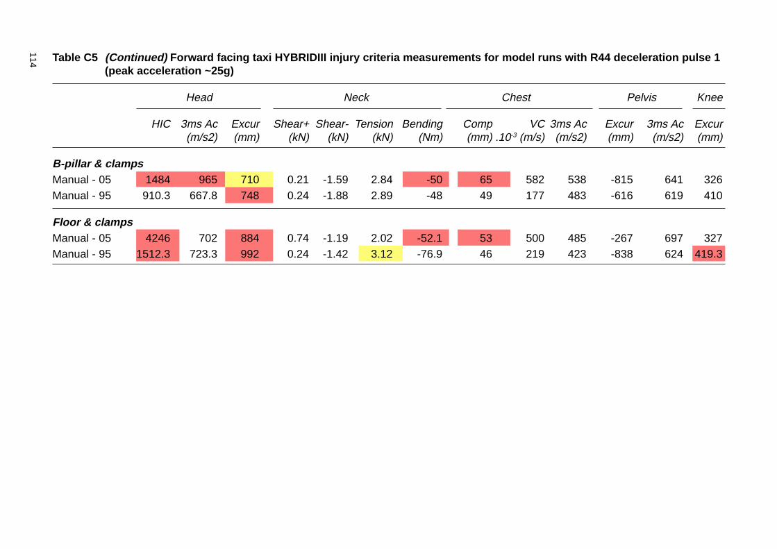
114 Table C5 (Continued) Forward facing taxi HYBRIDIII injury criteria measurements for model runs with R44 deceleration pulse 1(peak acceleration ~25g)
Head Neck Chest Pelvis Knee
HIC 3ms Ac Excur Shear+ Shear- Tension Bending Comp VC 3ms Ac Excur 3ms Ac Excur(m/s2) (mm) (kN) (kN) (kN) (Nm) (mm) .10-3 (m/s) (m/s2) (mm) (m/s2) (mm)
B-pillar & clampsManual - 05 1484 965 710 0.21 -1.59 2.84 -50 65 582 538 -815 641 326Manual - 95 910.3 667.8 748 0.24 -1.88 2.89 -48 49 177 483 -616 619 410
Floor & clampsManual - 05 4246 702 884 0.74 -1.19 2.02 -52.1 53 500 485 -267 697 327Manual - 95 1512.3 723.3 992 0.24 -1.42 3.12 -76.9 46 219 423 -838 624 419.3

115
Table C6 Forward facing taxi HYBRIDIII injury criteria measurements for model runs with R44 deceleration pulse 2(peak acceleration ~20g)
Head Neck Chest Pelvis Knee
HIC 3ms Ac Excur Shear+ Shear- Tension Bending Comp VC 3ms Ac Excur 3ms Ac Excur(m/s2) (mm) (kN) (kN) (kN) (Nm) (mm) .10-3 (m/s) (m/s2) (mm) (m/s2) (mm)
B-pillarManual 694.6 652.3 704 0.18 -1.49 2.62 -51 45 218.3 409.5 -452 560.7 295Electric 459.2 488.6 599 0.2 -1.34 1.95 -33.5 44 182.1 406.6 -103 528.2 333Surrogate 562.2 567.7 660 0.42 -1.5 2.11 -34.2 48 211 390.1 -769 520 331
FloorManual 14227 811.8 957 4.45 -1.17 3.9 -72 35 157 304.9 -147 589.5 312Electric 18660 676.7 841 5.31 -1 2.91 -71 30 163 280.9 -95 565.1 340Surrogate 39729 853.6 924 6.17 -1.21 4.21 -74.9 38 209 379.7 -106 545.3 347
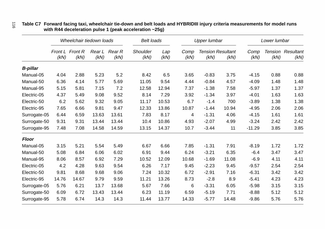
116 Table C7 Forward facing taxi, wheelchair tie-down and belt loads and HYBRIDIII injury criteria measurements for model runswith R44 deceleration pulse 1 (peak acceleration ~25g)
Wheelchair tiedown loads Belt loads Upper lumbar Lower lumbar
Front L Front R Rear L Rear R Shoulder Lap Comp Tension Resultant Comp Tension Resultant(kN) (kN) (kN) (kN) (kN) (kN) (kN) (kN) (kN) (kN) (kN) (kN)
B-pillarManual-05 4.04 2.88 5.23 5.2 8.42 6.5 3.65 -0.83 3.75 -4.15 0.88 0.88Manual-50 6.36 4.14 5.77 5.69 11.05 9.54 4.44 -0.84 4.57 -4.09 1.48 1.48Manual-95 5.15 5.81 7.15 7.2 12.58 12.94 7.37 -1.38 7.58 -5.97 1.37 1.37Electric-05 4.37 5.49 9.08 9.52 8.14 7.29 3.92 -1.34 3.97 -4.01 1.63 1.63Electric-50 6.2 5.62 9.32 9.05 11.17 10.53 6.7 -1.4 700 -3.89 1.38 1.38Electric-95 7.65 6.66 9.81 9.47 12.33 13.86 10.87 -1.44 10.94 -4.95 2.06 2.06Surrogate-05 6.44 6.59 13.63 13.61 7.83 8.17 4 -1.31 4.06 -4.15 1.61 1.61Surrogate-50 9.31 9.31 13.44 13.44 10.4 10.86 4.93 -2.07 4.99 -3.24 2.42 2.42Surrogate-95 7.48 7.08 14.58 14.59 13.15 14.37 10.7 -3.44 11 -11.29 3.85 3.85
FloorManual-05 3.15 5.21 5.54 5.49 6.67 6.66 7.85 -1.31 7.91 -8.19 1.72 1.72Manual-50 5.08 6.84 6.06 6.02 6.91 9.44 6.24 -3.21 6.35 -6.4 3.47 3.47Manual-95 8.06 8.57 6.92 7.29 10.52 12.09 10.68 -1.69 11.08 -6.9 4.11 4.11Electric-05 4.2 4.28 9.63 9.54 6.26 7.17 9.45 -2.23 9.45 -9.57 2.54 2.54Electric-50 9.81 8.68 9.68 9.06 7.24 10.32 6.72 -2.91 7.16 -6.31 3.42 3.42Electric-95 14.76 14.67 9.79 9.59 11.21 13.26 8.73 -2.8 8.9 -5.41 4.23 4.23Surrogate-05 5.76 6.21 13.7 13.68 5.67 7.66 6 -3.31 6.05 -5.98 3.15 3.15Surrogate-50 6.09 6.72 13.43 13.44 6.23 11.19 6.59 -5.19 7.71 -8.88 5.12 5.12Surrogate-95 5.78 6.74 14.3 14.3 11.44 13.77 14.33 -5.77 14.48 -9.86 5.76 5.76
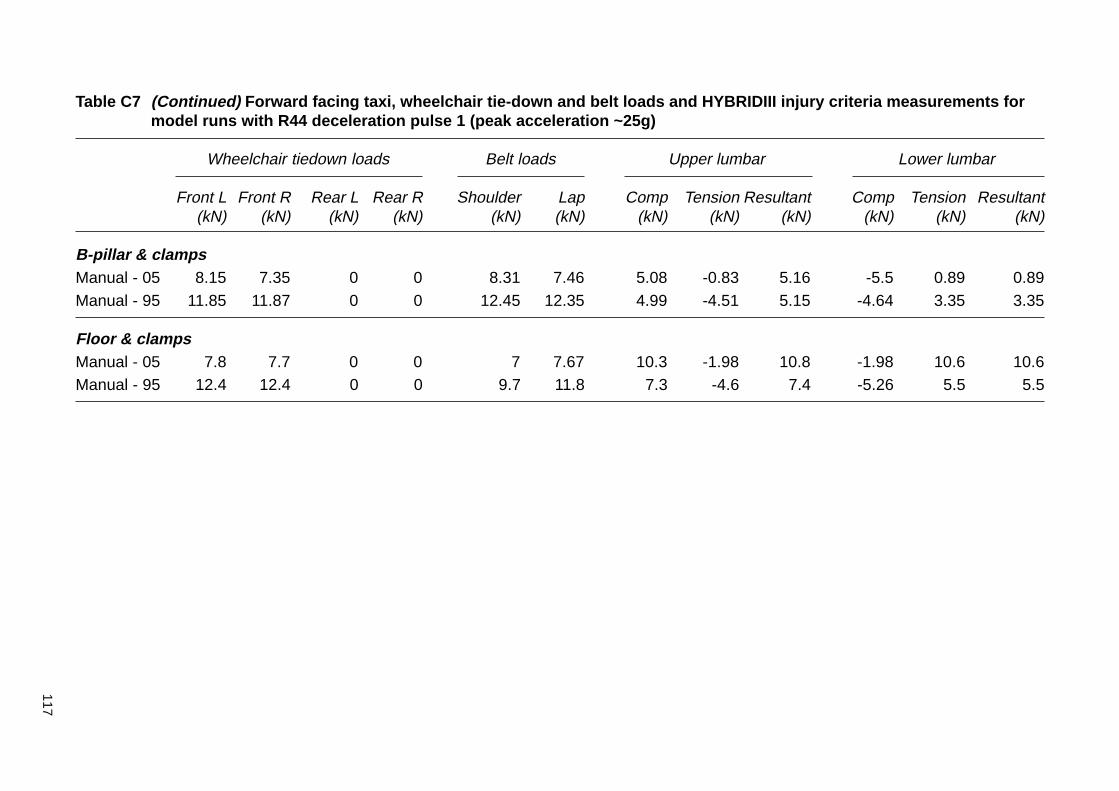
117
Table C7 (Continued) Forward facing taxi, wheelchair tie-down and belt loads and HYBRIDIII injury criteria measurements formodel runs with R44 deceleration pulse 1 (peak acceleration ~25g)
Wheelchair tiedown loads Belt loads Upper lumbar Lower lumbar
Front L Front R Rear L Rear R Shoulder Lap Comp Tension Resultant Comp Tension Resultant(kN) (kN) (kN) (kN) (kN) (kN) (kN) (kN) (kN) (kN) (kN) (kN)
B-pillar & clampsManual - 05 8.15 7.35 0 0 8.31 7.46 5.08 -0.83 5.16 -5.5 0.89 0.89Manual - 95 11.85 11.87 0 0 12.45 12.35 4.99 -4.51 5.15 -4.64 3.35 3.35
Floor & clampsManual - 05 7.8 7.7 0 0 7 7.67 10.3 -1.98 10.8 -1.98 10.6 10.6Manual - 95 12.4 12.4 0 0 9.7 11.8 7.3 -4.6 7.4 -5.26 5.5 5.5

118 Table C8 Forward facing taxi, wheelchair tie-down and belt loads and HYBRIDIII injury criteria measurements for model runswith R44 deceleration pulse 2 (peak acceleration ~20g)
Wheelchair tiedown loads Belt loads Upper lumbar Lower lumbar
Front L Front R Rear L Rear R Shoulder Lap Comp Tension Resultant Comp Tension Resultant(kN) (kN) (kN) (kN) (kN) (kN) (kN) (kN) (kN) (kN) (kN) (kN)
B-pillarManual 4.92 3.6 5.36 5.26 10.11 8.25 4.09 0.806 4.21 -3.76 1.56 4.34Electric 7.25 7.29 10.2 10.17 9.37 9.44 4.05 -1.56 4.12 -3.38 1.84 4.83Surrogate 5.6 5.8 7.56 7.39 10.04 9.08 6.34 -2.69 6.64 -3.06 1.16 6.72
FloorManual 4.45 5.88 5.4 5.33 6.4 8.2 5.57 -3.31 5.72 -5.57 3.4 6.51Electric 5.48 5.89 10.7 10.71 5.79 9.67 6.11 -4.49 7.2 -8.48 4.64 9.77Surrogate 8.41 7.51 7.67 7.28 7 9.45 5.95 -2.72 6.36 -5.37 3.36 7.3
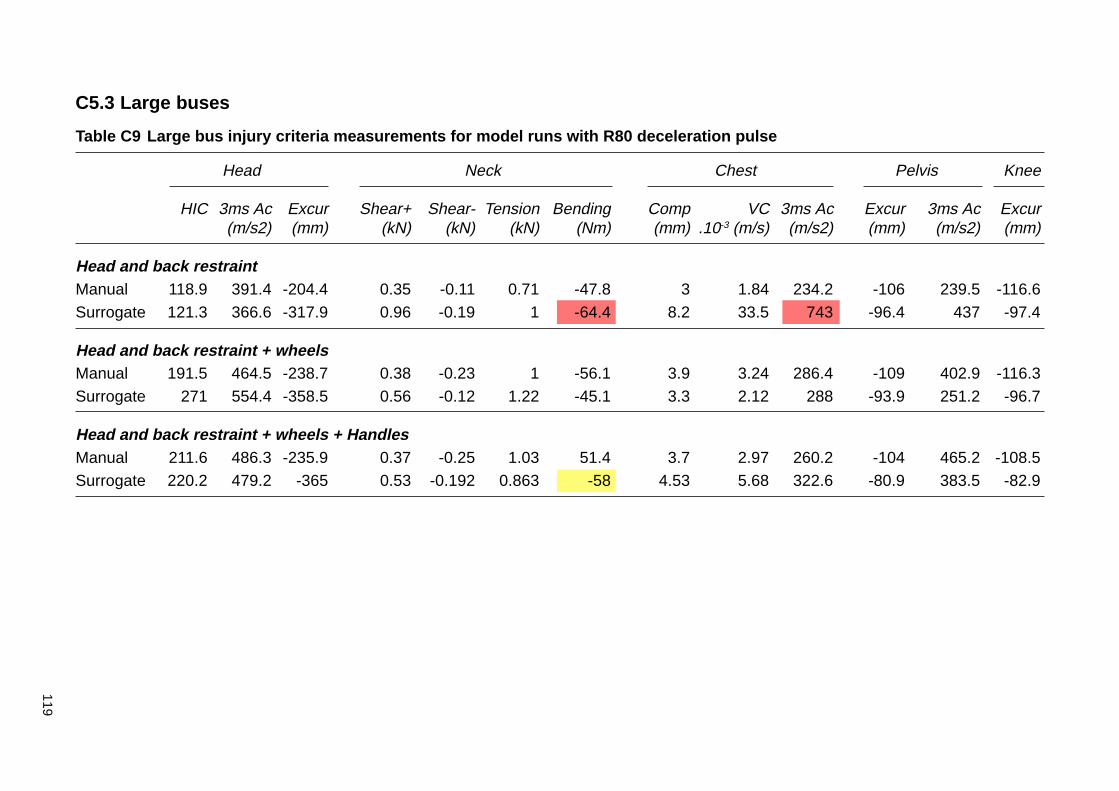
119
C5.3 Large buses
Table C9 Large bus injury criteria measurements for model runs with R80 deceleration pulse
Head Neck Chest Pelvis Knee
HIC 3ms Ac Excur Shear+ Shear- Tension Bending Comp VC 3ms Ac Excur 3ms Ac Excur(m/s2) (mm) (kN) (kN) (kN) (Nm) (mm) .10-3 (m/s) (m/s2) (mm) (m/s2) (mm)
Head and back restraintManual 118.9 391.4 -204.4 0.35 -0.11 0.71 -47.8 3 1.84 234.2 -106 239.5 -116.6Surrogate 121.3 366.6 -317.9 0.96 -0.19 1 -64.4 8.2 33.5 743 -96.4 437 -97.4
Head and back restraint + wheelsManual 191.5 464.5 -238.7 0.38 -0.23 1 -56.1 3.9 3.24 286.4 -109 402.9 -116.3Surrogate 271 554.4 -358.5 0.56 -0.12 1.22 -45.1 3.3 2.12 288 -93.9 251.2 -96.7
Head and back restraint + wheels + HandlesManual 211.6 486.3 -235.9 0.37 -0.25 1.03 51.4 3.7 2.97 260.2 -104 465.2 -108.5Surrogate 220.2 479.2 -365 0.53 -0.192 0.863 -58 4.53 5.68 322.6 -80.9 383.5 -82.9
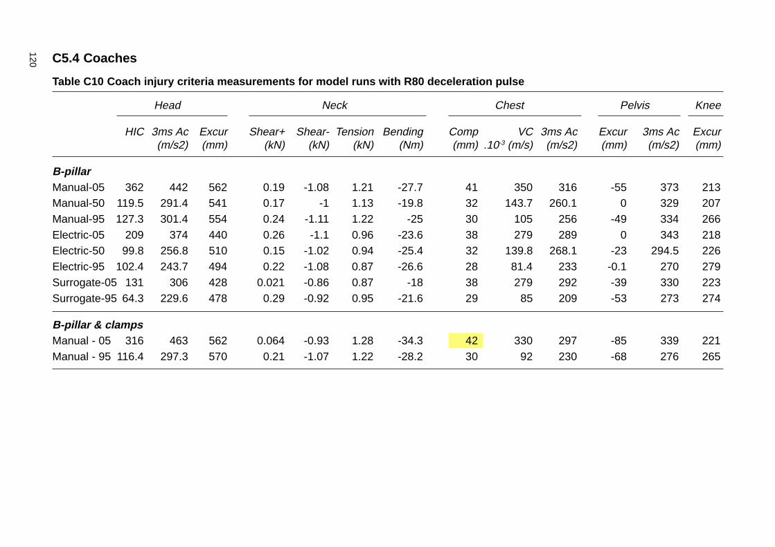
120 C5.4 Coaches
Table C10 Coach injury criteria measurements for model runs with R80 deceleration pulse
Head Neck Chest Pelvis Knee
HIC 3ms Ac Excur Shear+ Shear- Tension Bending Comp VC 3ms Ac Excur 3ms Ac Excur(m/s2) (mm) (kN) (kN) (kN) (Nm) (mm) .10-3 (m/s) (m/s2) (mm) (m/s2) (mm)
B-pillarManual-05 362 442 562 0.19 -1.08 1.21 -27.7 41 350 316 -55 373 213Manual-50 119.5 291.4 541 0.17 -1 1.13 -19.8 32 143.7 260.1 0 329 207Manual-95 127.3 301.4 554 0.24 -1.11 1.22 -25 30 105 256 -49 334 266Electric-05 209 374 440 0.26 -1.1 0.96 -23.6 38 279 289 0 343 218Electric-50 99.8 256.8 510 0.15 -1.02 0.94 -25.4 32 139.8 268.1 -23 294.5 226Electric-95 102.4 243.7 494 0.22 -1.08 0.87 -26.6 28 81.4 233 -0.1 270 279Surrogate-05 131 306 428 0.021 -0.86 0.87 -18 38 279 292 -39 330 223Surrogate-95 64.3 229.6 478 0.29 -0.92 0.95 -21.6 29 85 209 -53 273 274
B-pillar & clampsManual - 05 316 463 562 0.064 -0.93 1.28 -34.3 42 330 297 -85 339 221Manual - 95 116.4 297.3 570 0.21 -1.07 1.22 -28.2 30 92 230 -68 276 265
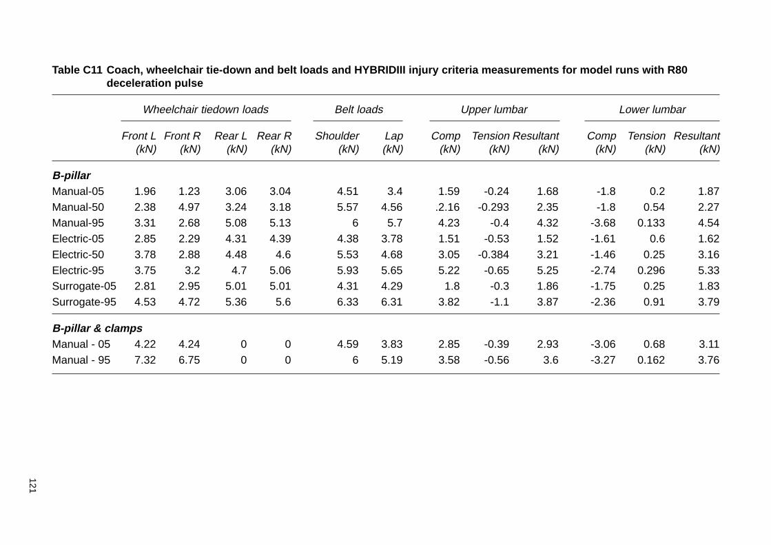
121
Table C11 Coach, wheelchair tie-down and belt loads and HYBRIDIII injury criteria measurements for model runs with R80deceleration pulse
Wheelchair tiedown loads Belt loads Upper lumbar Lower lumbar
Front L Front R Rear L Rear R Shoulder Lap Comp Tension Resultant Comp Tension Resultant(kN) (kN) (kN) (kN) (kN) (kN) (kN) (kN) (kN) (kN) (kN) (kN)
B-pillarManual-05 1.96 1.23 3.06 3.04 4.51 3.4 1.59 -0.24 1.68 -1.8 0.2 1.87Manual-50 2.38 4.97 3.24 3.18 5.57 4.56 .2.16 -0.293 2.35 -1.8 0.54 2.27Manual-95 3.31 2.68 5.08 5.13 6 5.7 4.23 -0.4 4.32 -3.68 0.133 4.54Electric-05 2.85 2.29 4.31 4.39 4.38 3.78 1.51 -0.53 1.52 -1.61 0.6 1.62Electric-50 3.78 2.88 4.48 4.6 5.53 4.68 3.05 -0.384 3.21 -1.46 0.25 3.16Electric-95 3.75 3.2 4.7 5.06 5.93 5.65 5.22 -0.65 5.25 -2.74 0.296 5.33Surrogate-05 2.81 2.95 5.01 5.01 4.31 4.29 1.8 -0.3 1.86 -1.75 0.25 1.83Surrogate-95 4.53 4.72 5.36 5.6 6.33 6.31 3.82 -1.1 3.87 -2.36 0.91 3.79
B-pillar & clampsManual - 05 4.22 4.24 0 0 4.59 3.83 2.85 -0.39 2.93 -3.06 0.68 3.11Manual - 95 7.32 6.75 0 0 6 5.19 3.58 -0.56 3.6 -3.27 0.162 3.76

122
Appendix D: Surrogate wheelchair specifications
D1 GeneralDesign, dimensional, material, and performance specifications areprovided for a surrogate wheelchair (SWC) that produces representativeloading and seating conditions of a powered wheelchair for testing WTORSto the requirements of this standard2.
D2 SpecificationsThe surrogate wheelchair shall:
a be of rigid durable construction, such that there is no permanentdeformation of the frame, seat surface, or seatback in a 48 km/h, 20 gfrontal impact test with a 76.3 kg ATD positioned and restrained in theSWC;
b have a total mass of 85 kg + 1 kg;
c conform with the dimensions shown in Figures D1 through D4,
d allow for adjustment to accommodate components and end fittings ofdifferent types of tiedown systems;
e provide two front securement points and two rear securement points forfour-point strap-type tiedowns at the locations indicated in Figure D1and with the geometry specified in Figure D4;
f provide pelvic restraint anchor points on both sides of the surrogatewheelchair located as shown in Figure D1;
g have a centre of gravity located 142 mm + 25 mm forward of the rearaxle and 287 mm + 25 mm above the ground plane for the range offrame-to-floor clearance adjustments allowed;
h have a rigid, flat seat surface with dimensions shown in Figures D3 that isoriented at an angle of 4o + 1.5 o to the horizontal (front end up), as shownin Figures D1 and D3, when the SWC tyres are inflated in accordancewith (m) and (n) and are resting on a flat horizontal surface;
i have a rigid seatback with height and width dimensions indicated inFigures D2 and D3 that is oriented at 8o + 1.5 o to the vertical when thetyres of the SWC are resting on a flat horizontal surface and inflated inaccordance with (m) and (n);
j have a 20-mm to 30-mm thick firm (i.e., shore-A hardness = 60 to 80)rubber pad with height and width dimensions indicated in Figures D1and D2 fixed to the front surface of the rigid seatback;
2 Details for the design, fabrication, and maintenance of a suitable surrogate wheelchair areavailable in SAE 2252 - Surrogate wheelchair drawing package and maintenance manual.
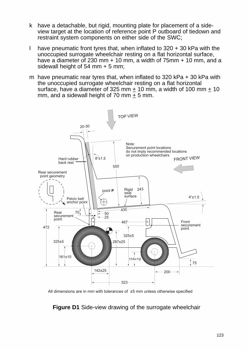
123
k have a detachable, but rigid, mounting plate for placement of a side-view target at the location of reference point P outboard of tiedown andrestraint system components on either side of the SWC;
l have pneumatic front tyres that, when inflated to 320 + 30 kPa with theunoccupied surrogate wheelchair resting on a flat horizontal surface,have a diameter of 230 mm + 10 mm, a width of 75mm + 10 mm, and asidewall height of 54 mm + 5 mm;
m have pneumatic rear tyres that, when inflated to 320 kPa + 30 kPa withthe unoccupied surrogate wheelchair resting on a flat horizontalsurface, have a diameter of 325 mm + 10 mm, a width of 100 mm + 10mm, and a sidewall height of 70 mm + 5 mm.
472
325±5
161±10
142±25
287±25
325±5
116±10
2550
467
43070
4o±1.5
8o±1.5
20-30
TOP VIEW
FRONT VIEW
Pelvic beltanchor point
Rear securementpoint geometry
Rearsecurementpoint
Frontsecurementpoint
point P Rigidseatsurface
Note:Securement point locationsdo not imply recommended locationson production wheelchairs
550
243
Hard rubberback rest
523
200
75
All dimensions are in mm with tolerances of ±5 mm unless otherwise specified
Figure D1 Side-view drawing of the surrogate wheelchair
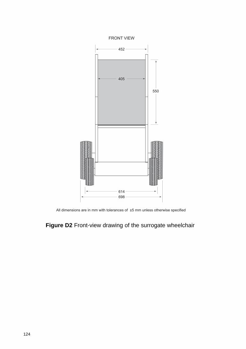
124
452
614
698
550
FRONT VIEW
All dimensions are in mm with tolerances of ±5 mm unless otherwise specified
405
Figure D2 Front-view drawing of the surrogate wheelchair
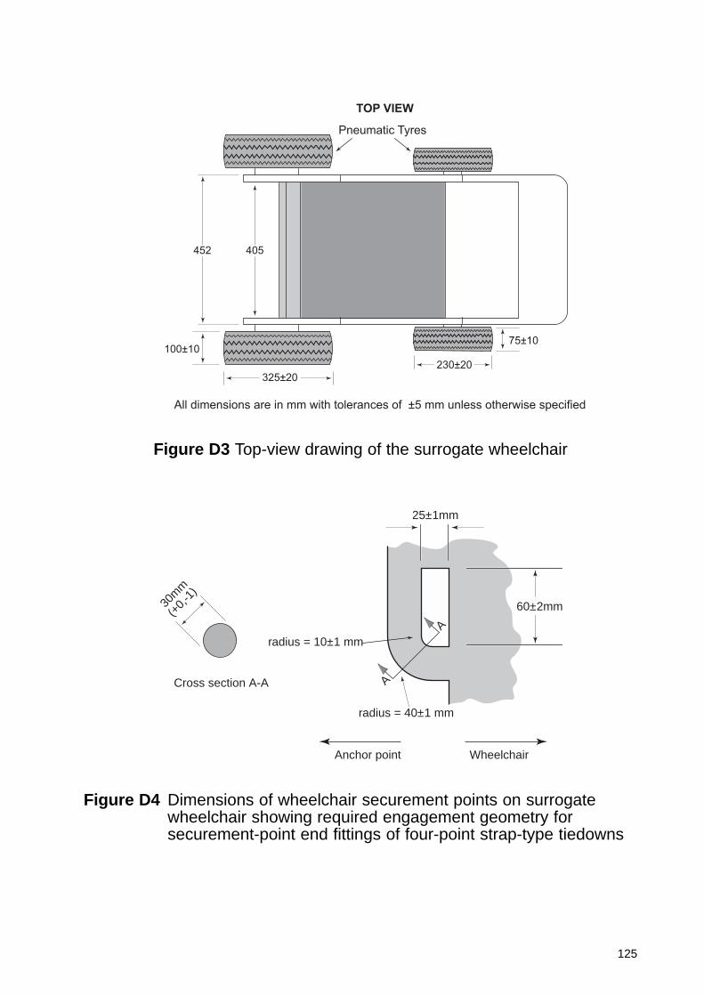
125
75±10
230±20
325±20
100±10
452 405
TOP VIEW
Pneumatic Tyres
All dimensions are in mm with tolerances of ±5 mm unless otherwise specified
Figure D4 Dimensions of wheelchair securement points on surrogatewheelchair showing required engagement geometry forsecurement-point end fittings of four-point strap-type tiedowns
Figure D3 Top-view drawing of the surrogate wheelchair
25±1mm
60±2mm
radius = 10±1 mm
radius = 40±1 mm
A
A
Anchor point Wheelchair
Cross section A-A
30m
m
(+0,
-1)
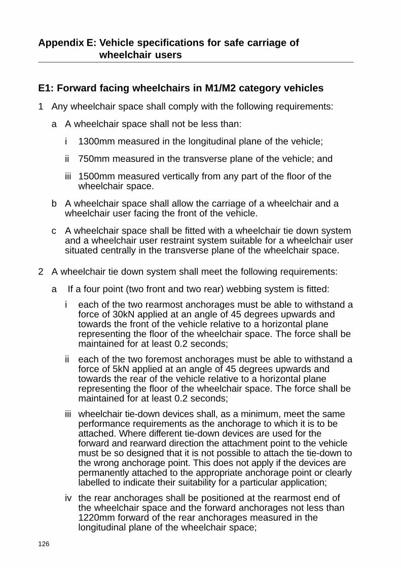
126
Appendix E: Vehicle specifications for safe carriage ofwheelchair users
E1: Forward facing wheelchairs in M1/M2 category vehicles
1 Any wheelchair space shall comply with the following requirements:
a A wheelchair space shall not be less than:
i 1300mm measured in the longitudinal plane of the vehicle;
ii 750mm measured in the transverse plane of the vehicle; and
iii 1500mm measured vertically from any part of the floor of thewheelchair space.
b A wheelchair space shall allow the carriage of a wheelchair and awheelchair user facing the front of the vehicle.
c A wheelchair space shall be fitted with a wheelchair tie down systemand a wheelchair user restraint system suitable for a wheelchair usersituated centrally in the transverse plane of the wheelchair space.
2 A wheelchair tie down system shall meet the following requirements:
a If a four point (two front and two rear) webbing system is fitted:
i each of the two rearmost anchorages must be able to withstand aforce of 30kN applied at an angle of 45 degrees upwards andtowards the front of the vehicle relative to a horizontal planerepresenting the floor of the wheelchair space. The force shall bemaintained for at least 0.2 seconds;
ii each of the two foremost anchorages must be able to withstand aforce of 5kN applied at an angle of 45 degrees upwards andtowards the rear of the vehicle relative to a horizontal planerepresenting the floor of the wheelchair space. The force shall bemaintained for at least 0.2 seconds;
iii wheelchair tie-down devices shall, as a minimum, meet the sameperformance requirements as the anchorage to which it is to beattached. Where different tie-down devices are used for theforward and rearward direction the attachment point to the vehiclemust be so designed that it is not possible to attach the tie-down tothe wrong anchorage point. This does not apply if the devices arepermanently attached to the appropriate anchorage point or clearlylabelled to indicate their suitability for a particular application;
iv the rear anchorages shall be positioned at the rearmost end ofthe wheelchair space and the forward anchorages not less than1220mm forward of the rear anchorages measured in thelongitudinal plane of the wheelchair space;
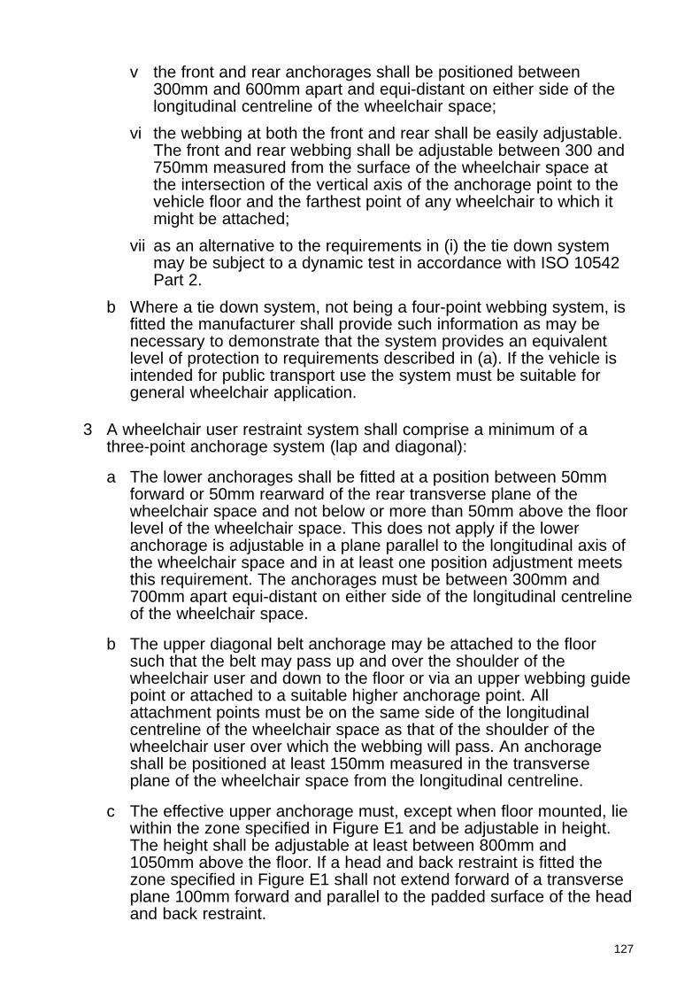
127
v the front and rear anchorages shall be positioned between300mm and 600mm apart and equi-distant on either side of thelongitudinal centreline of the wheelchair space;
vi the webbing at both the front and rear shall be easily adjustable.The front and rear webbing shall be adjustable between 300 and750mm measured from the surface of the wheelchair space atthe intersection of the vertical axis of the anchorage point to thevehicle floor and the farthest point of any wheelchair to which itmight be attached;
vii as an alternative to the requirements in (i) the tie down systemmay be subject to a dynamic test in accordance with ISO 10542Part 2.
b Where a tie down system, not being a four-point webbing system, isfitted the manufacturer shall provide such information as may benecessary to demonstrate that the system provides an equivalentlevel of protection to requirements described in (a). If the vehicle isintended for public transport use the system must be suitable forgeneral wheelchair application.
3 A wheelchair user restraint system shall comprise a minimum of athree-point anchorage system (lap and diagonal):
a The lower anchorages shall be fitted at a position between 50mmforward or 50mm rearward of the rear transverse plane of thewheelchair space and not below or more than 50mm above the floorlevel of the wheelchair space. This does not apply if the loweranchorage is adjustable in a plane parallel to the longitudinal axis ofthe wheelchair space and in at least one position adjustment meetsthis requirement. The anchorages must be between 300mm and700mm apart equi-distant on either side of the longitudinal centrelineof the wheelchair space.
b The upper diagonal belt anchorage may be attached to the floorsuch that the belt may pass up and over the shoulder of thewheelchair user and down to the floor or via an upper webbing guidepoint or attached to a suitable higher anchorage point. Allattachment points must be on the same side of the longitudinalcentreline of the wheelchair space as that of the shoulder of thewheelchair user over which the webbing will pass. An anchorageshall be positioned at least 150mm measured in the transverseplane of the wheelchair space from the longitudinal centreline.
c The effective upper anchorage must, except when floor mounted, liewithin the zone specified in Figure E1 and be adjustable in height.The height shall be adjustable at least between 800mm and1050mm above the floor. If a head and back restraint is fitted thezone specified in Figure E1 shall not extend forward of a transverseplane 100mm forward and parallel to the padded surface of the headand back restraint.
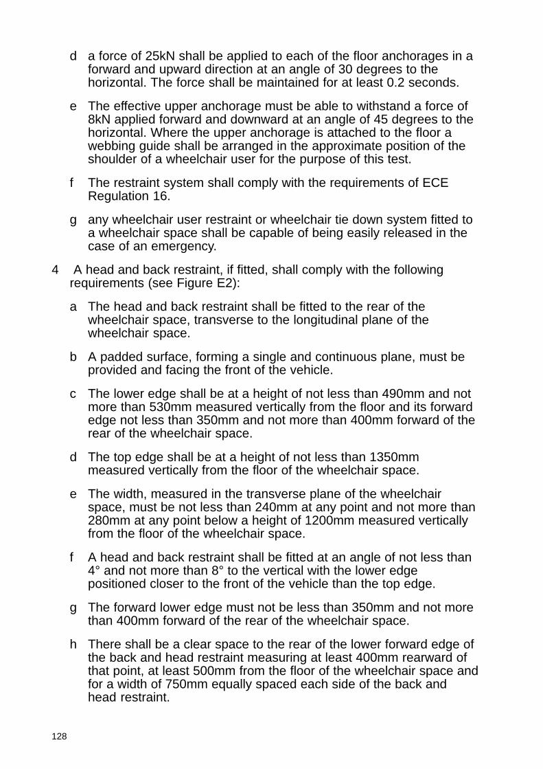
128
d a force of 25kN shall be applied to each of the floor anchorages in aforward and upward direction at an angle of 30 degrees to thehorizontal. The force shall be maintained for at least 0.2 seconds.
e The effective upper anchorage must be able to withstand a force of8kN applied forward and downward at an angle of 45 degrees to thehorizontal. Where the upper anchorage is attached to the floor awebbing guide shall be arranged in the approximate position of theshoulder of a wheelchair user for the purpose of this test.
f The restraint system shall comply with the requirements of ECERegulation 16.
g any wheelchair user restraint or wheelchair tie down system fitted toa wheelchair space shall be capable of being easily released in thecase of an emergency.
4 A head and back restraint, if fitted, shall comply with the followingrequirements (see Figure E2):
a The head and back restraint shall be fitted to the rear of thewheelchair space, transverse to the longitudinal plane of thewheelchair space.
b A padded surface, forming a single and continuous plane, must beprovided and facing the front of the vehicle.
c The lower edge shall be at a height of not less than 490mm and notmore than 530mm measured vertically from the floor and its forwardedge not less than 350mm and not more than 400mm forward of therear of the wheelchair space.
d The top edge shall be at a height of not less than 1350mmmeasured vertically from the floor of the wheelchair space.
e The width, measured in the transverse plane of the wheelchairspace, must be not less than 240mm at any point and not more than280mm at any point below a height of 1200mm measured verticallyfrom the floor of the wheelchair space.
f A head and back restraint shall be fitted at an angle of not less than4° and not more than 8° to the vertical with the lower edgepositioned closer to the front of the vehicle than the top edge.
g The forward lower edge must not be less than 350mm and not morethan 400mm forward of the rear of the wheelchair space.
h There shall be a clear space to the rear of the lower forward edge ofthe back and head restraint measuring at least 400mm rearward ofthat point, at least 500mm from the floor of the wheelchair space andfor a width of 750mm equally spaced each side of the back andhead restraint.
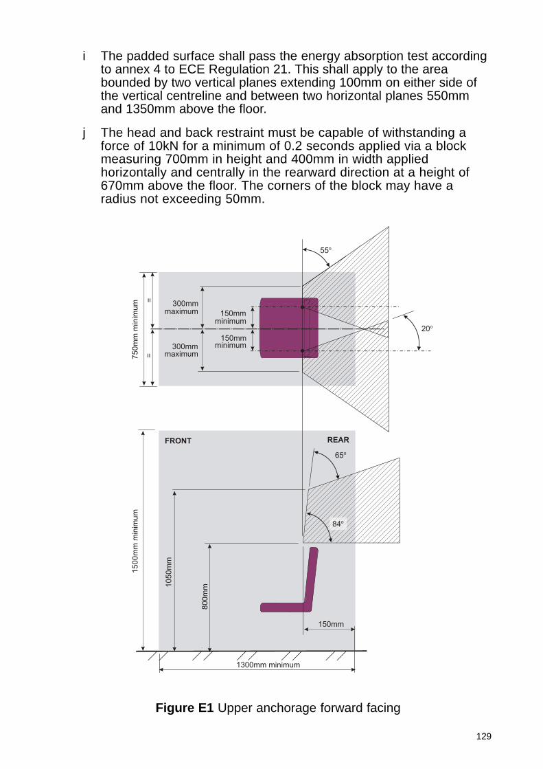
129
i The padded surface shall pass the energy absorption test accordingto annex 4 to ECE Regulation 21. This shall apply to the areabounded by two vertical planes extending 100mm on either side ofthe vertical centreline and between two horizontal planes 550mmand 1350mm above the floor.
j The head and back restraint must be capable of withstanding aforce of 10kN for a minimum of 0.2 seconds applied via a blockmeasuring 700mm in height and 400mm in width appliedhorizontally and centrally in the rearward direction at a height of670mm above the floor. The corners of the block may have aradius not exceeding 50mm.
Figure E1 Upper anchorage forward facing
150mmminimum
1300mm minimum
FRONT REAR
150mm
65o
==
150mmminimum
20o
55o
300mmmaximum
300mmmaximum7
50m
m m
inim
um
1500m
m m
inim
um
1050m
m
800m
m
84o
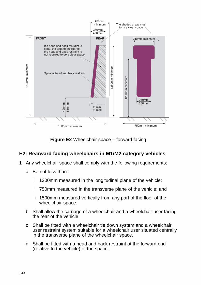
130
1200m
m m
inim
um
13
50
mm
min
imu
m
4o min8o max4
90
mm
1500m
m m
inim
um
If a head and back restraint isfitted, the area to the rear ofthe head and back restraint isnot required to be a clear space.
Optional head and back restraint
400mm
350mm
FRONT REAR
The shaded areas mustform a clear space
240mm minimum
280mm
750mm minimum1300mm minimum
530m
m
240mm
400mm
minimum
Figure E2 Wheelchair space – forward facing
E2: Rearward facing wheelchairs in M1/M2 category vehicles
1 Any wheelchair space shall comply with the following requirements:
a Be not less than:
i 1300mm measured in the longitudinal plane of the vehicle;
ii 750mm measured in the transverse plane of the vehicle; and
iii 1500mm measured vertically from any part of the floor of thewheelchair space.
b Shall allow the carriage of a wheelchair and a wheelchair user facingthe rear of the vehicle.
c Shall be fitted with a wheelchair tie down system and a wheelchairuser restraint system suitable for a wheelchair user situated centrallyin the transverse plane of the wheelchair space.
d Shall be fitted with a head and back restraint at the forward end(relative to the vehicle) of the space.

131
2 A wheelchair tie down system shall meet the following requirements:
a A tie down system shall, subject to sub-paragraph (b), consist of awebbing system comprising two separate straps or a system withtwo attachment points on the wheelchair and a single attachmentpoint to the vehicle and meeting the following requirements:
i the anchorage or combined anchorages must be able towithstand a force of 10kN applied at an angle of 45 degreesupwards and towards the rear of the vehicle relative to ahorizontal plane representing the floor of the wheelchair space.The force shall be maintained for at least 0.2 seconds;
ii the wheelchair tie-down system shall, as a minimum, meet thesame performance requirements as the anchorage to which it isto be attached;
iii the anchorage(s) shall be positioned at floor level at the forwardend of the wheelchair space.
iv If a single anchorage is fitted it must be on the centrallongitudinal centreline of the wheelchair space and if twoanchorages are fitted they must be between 300mm and 600mmapart and equi-distant on either side of the longitudinal centrelineof the wheelchair space;
v the webbing shall be easily adjustable between 300mm and750mm measured from the surface of the wheelchair space atthe intersection of the vertical axis of the anchorage and thefarthest point of any wheelchair to which it might be attached.
b Where an alternative wheelchair tie down system is fitted themanufacturer shall provide such information as may be necessary todemonstrate that the system provides an equivalent level ofprotection to requirements described in (a). If the vehicle is intendedfor public transport use the system must be suitable for generalwheelchair application.
3 A wheelchair user restraint system shall comprise a minimum of athree-point anchorage system (lap and diagonal) complying with thefollowing:
a The lower anchorages shall be fitted at a position between 50mmforward and 50mm rearward of the formost transverse plane of thewheelchair space and not below or more than 50mm above the floorlevel of the wheelchair space. This does not apply if the loweranchorage is adjustable in a plane parallel to the longitudinal axis ofthe wheelchair space and in at least one position adjustment meetsthis requirement. The anchorages must be between 300mm and700mm apart equi-distant on either side of the longitudinal centrelineof the wheelchair space.
132
b The effective upper diagonal belt anchorage must be attached to asuitable anchorage point and on the same side of the longitudinalcentreline of the wheelchair space as that of the shoulder of thewheelchair user over which the webbing will pass. An anchorageshall be positioned at least 150mm measured in the transverseplane of the wheelchair space from the longitudinal centreline.
c The effective upper anchorage must lie within the zone specified inFigure E3 and be adjustable in height. The height shall be adjustableat least between 800mm and 1050mm above the floor. The zonespecified in Figure E3 shall not extend rearward of a transverseplane 100mm rearward and parallel to the padded surface of thehead and back restraint.
d A force of 5kN shall be applied to each of the floor anchorages in arearward and upward direction at an angle of 30 degrees to thehorizontal. The force shall be maintained for at least 0.2 seconds.
e The effective upper anchorage must be able to withstand a force of2kN applied rearward and downward at an angle of 45 degrees tothe horizontal. Where the upper anchorage is attached to the floor awebbing guide shall be arranged in the approximate position of theshoulder of a wheelchair user for the purpose of this test.
f The restraint system shall comply with the requirements of ECERegulation 16.
g Any wheelchair user restraint or wheelchair tie down system fitted toa wheelchair space shall be capable of being easily released in thecase of an emergency.
4 A head and back restraint shall be fitted complying with the followingrequirements (see Figure E4):
a The bottom edge of the head and back restraint shall be at a heightof not less than 490mm and not more than 530mm measuredvertically from the floor of the wheelchair space.
b The top edge of a back and head restraint shall be at a height of notless than 1350mm measured vertically from the floor of thewheelchair space.
c The width shall be not less than 240mm at any point and not morethan 280mm at any point up to a height of 1200mm measuredvertically from the floor of the wheelchair space.
d A back and head restraint shall be fitted at an angle of not less than4° and not more than 8° to the vertical with the bottom edge of theback and head restraint positioned closer to the rear of the vehiclethan the top edge.
e The lower rearmost edge of the head and back restraint shall be350mm to 400mm to the rear of the forward edge of the wheelchairspace.
133
f There shall be a clear space forward of the lower rearmost edge ofthe head and back restraint measuring at least 400mm forward ofthat point, at least 500mm above the floor of the wheelchair spaceand for a width of 750mm equally spaced about the longitudinalcentreline of the wheelchair space.
g The surface of the back and head restraint shall be padded and forma single and continuous plane facing the rear of the vehicle. Thepadded surface shall pass the energy absorption test according toannex 4 to ECE Regulation 21. This shall apply to the area boundedby two vertical planes extending 100mm on either side of the verticalcentreline and between two horizontal planes 550mm and 1350mmabove the floor.
h The head and back restraint must be capable of withstanding aforce of 100kN for a minimum of 0.2 seconds applied via a blockmeasuring 700mm in height and 400mm in width appliedhorizontally and centrally in the rearward direction at a height of670mm above the floor. The corners of the block may have aradius not exceeding 50mm.
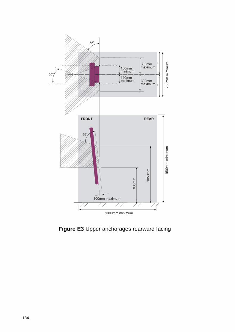
134
150mmminimum
1300mm minimum
FRONT REAR
65o
==
150mmminimum
20o
55o
100mm maximum
300mmmaximum
300mmmaximum
750m
m m
imim
um
15
00
mm
mim
imu
m
80
0m
m 10
50
mm
Figure E3 Upper anchorages rearward facing
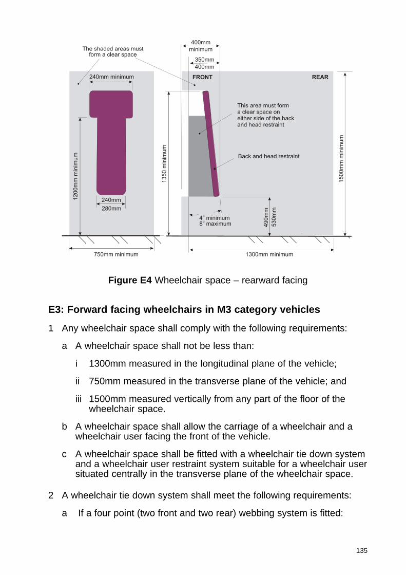
135
E3: Forward facing wheelchairs in M3 category vehicles
1 Any wheelchair space shall comply with the following requirements:
a A wheelchair space shall not be less than:
i 1300mm measured in the longitudinal plane of the vehicle;
ii 750mm measured in the transverse plane of the vehicle; and
iii 1500mm measured vertically from any part of the floor of thewheelchair space.
b A wheelchair space shall allow the carriage of a wheelchair and awheelchair user facing the front of the vehicle.
c A wheelchair space shall be fitted with a wheelchair tie down systemand a wheelchair user restraint system suitable for a wheelchair usersituated centrally in the transverse plane of the wheelchair space.
2 A wheelchair tie down system shall meet the following requirements:
a If a four point (two front and two rear) webbing system is fitted:
The shaded areas mustform a clear space
240mm minimum
400mm
350mm
280mm
FRONT REAR
This area must form a clear space on either side of the back and head restraint
Back and head restraint
490m
m
4o minimum
8o maximum
1350 m
inim
um
1500m
m m
inim
um
1200m
m m
inim
um
1300mm minimum750mm minimum
minimum
400mm
240mm
53
0m
m
Figure E4 Wheelchair space – rearward facing
136
i each of the two foremost anchorages must be able to withstand aforce of 5kN applied at an angle of 45 degrees upwards andtowards the rear of the vehicle relative to a horizontal planerepresenting the floor of the wheelchair space. The force shall bemaintained for at least 0.2 seconds;
ii each of the two rearmost anchorages must be able to withstand aforce of 20kN applied at an angle of 45 degrees upwards andtowards the front of the vehicle relative to a horizontal planerepresenting the floor of the wheelchair space. The force shall bemaintained for at least 0.2 seconds;
iii wheelchair tie-down equipment shall, as a minimum, meet thesame performance requirements as the anchorage to which it isto be attached. Where the different tie-downs are used for theforward and rearward direction the fittings must be designed sothat it is not possible to attach the tie-down to the wronganchorage;
iv the rear anchorages shall be positioned at the rearmost end ofthe wheelchair space and the forward anchorages not less than1220mm forward of the rear anchorages measured in thelongitudinal plane of the wheelchair space;
v the front and rear anchorages shall be positioned between300mm and 600mm apart and equi-distant on either side of thelongitudinal centreline of the wheelchair space;
vi the webbing at both the front and rear shall be easily adjustable.The front and rear webbing shall be adjustable between 300and750mm measured from the surface of the wheelchair space atthe intersection of the vertical axis of the anchorage and thefarthest point of any wheelchair to which it might be attached.
b Where a tie down system that is not a four-point webbing system isfitted the manufacturer shall provide such information as may benecessary to demonstrate that the system provides an equivalentlevel of protection to requirements described in (a) and, if the vehicleis intended for public transport use, that it is suitable for generalwheelchair application.
3 A wheelchair user restraint system shall comprise a minimum of athree-point anchorage system (lap and diagonal):
a The lower anchorages shall be attached to the floor at a positionbetween 0mm and 400mm forward of the rear of the wheelchairspace and between 300mm and 700mm apart and equi-distant oneither side of the longitudinal centreline of the wheelchair space.
b The upper diagonal belt anchorage may be attached to the floorsuch that the belt may pass up and over the shoulder of thewheelchair user and down to the floor or via an upper webbing guide
137
point or attached to a suitable higher anchorage point. Allattachment points must be on the same side of the longitudinalcentreline of the wheelchair space as that of the shoulder of thewheelchair user over which the webbing will pass. An anchorageshall be positioned at least 150mm measured in the transverseplane of the wheelchair space from the longitudinal centreline and inthe case of an upper anchorage or webbing guide not forward of thepadded surface of the head and back restraint.
c The effective upper anchorage must, except when floor mounted, liewithin the zone specified in Figure E5 and be adjustable in height.The height shall be adjustable at least between 800mm and1050mm above the floor. If a head and back restraint is fitted thezone specified in Figure E5 shall not extend forward of a transverseplane 100mm forward and parallel to the padded surface of the headand back restraint.
d a force of 16kN shall be applied to each of the floor anchorages in aforward and upward direction at an angle of 30 degrees to thehorizontal. The force shall be maintained for at least 0.2 seconds.
e The effective upper anchorage must be able to withstand a force of5kN applied forward and downward at an angle of 45 degrees to thehorizontal. Where the upper anchorage is attached to the floor awebbing guide shall be arranged in the approximate position of theshoulder of a wheelchair user for the purpose of this test.
f any wheelchair user restraint or wheelchair tie down system fitted toa wheelchair space shall be capable of being easily released in thecase of an emergency.
4 A head and back restraint may be fitted to the rear of the wheelchairspace meeting the following requirements (see Figure E6):
a The bottom edge of the head and back restraint shall be at a heightof not less than 490mm and not more than 530mm measuredvertically from the floor of the wheelchair space.
b The top edge of a head and back restraint shall be at a height of notless than 1350mm measured vertically from the floor of thewheelchair space.
c The width shall be not less than 240mm at any point and not morethan 280mm at any point up to a height of 1200mm measuredvertically from the floor of the wheelchair space.
d T head and back restraint shall be fitted at an angle of not less than4° and not more than 8° to the vertical with the bottom edge of theback and head restraint positioned closer to the front of the vehiclethan the top edge.
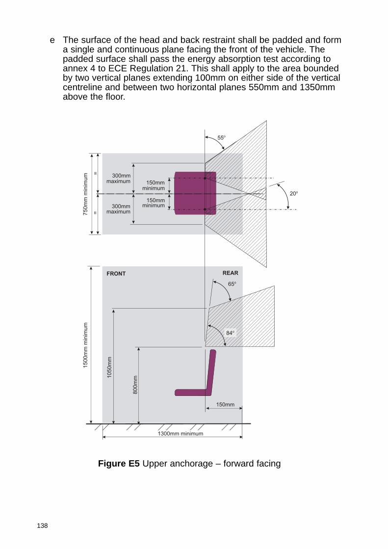
138
e The surface of the head and back restraint shall be padded and forma single and continuous plane facing the front of the vehicle. Thepadded surface shall pass the energy absorption test according toannex 4 to ECE Regulation 21. This shall apply to the area boundedby two vertical planes extending 100mm on either side of the verticalcentreline and between two horizontal planes 550mm and 1350mmabove the floor.
Figure E5 Upper anchorage – forward facing
150mmminimum
1300mm minimum
FRONT REAR
150mm
65o
==
150mmminimum
20o
55o
300mmmaximum
300mmmaximum7
50m
m m
inim
um
1500m
m m
inim
um
1050m
m
800m
m
84o
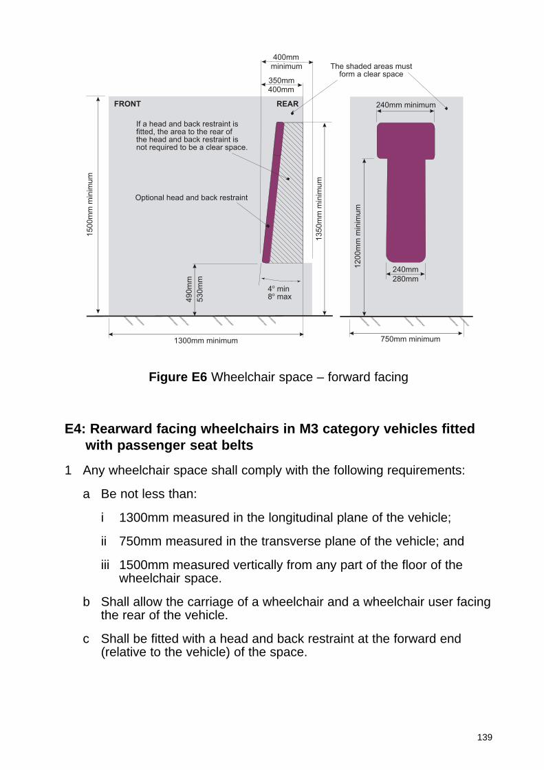
139
E4: Rearward facing wheelchairs in M3 category vehicles fittedwith passenger seat belts
1 Any wheelchair space shall comply with the following requirements:
a Be not less than:
i 1300mm measured in the longitudinal plane of the vehicle;
ii 750mm measured in the transverse plane of the vehicle; and
iii 1500mm measured vertically from any part of the floor of thewheelchair space.
b Shall allow the carriage of a wheelchair and a wheelchair user facingthe rear of the vehicle.
c Shall be fitted with a head and back restraint at the forward end(relative to the vehicle) of the space.
1200m
m m
inim
um
1350m
m m
inim
um
4o min8o max4
90m
m
1500m
m m
inim
um
If a head and back restraint isfitted, the area to the rear ofthe head and back restraint isnot required to be a clear space.
Optional head and back restraint
400mm
350mm
FRONT REAR
The shaded areas mustform a clear space
240mm minimum
280mm
750mm minimum1300mm minimum
530m
m
240mm
400mm
minimum
Figure E6 Wheelchair space – forward facing

140
2 A wheelchair tie down system, if fitted, shall comply with the followingrequirements:
a A tie down system shall, subject to sub-paragraph (b), consist of awebbing system comprising two separate straps or a system withtwo attachment points on the wheelchair and a single attachmentpoint to the vehicle and meeting the following requirements:
i The anchorage or combined anchorages must be able towithstand a force of 5kN applied at an angle of 45 degreesupwards and towards the rear of the vehicle relative to ahorizontal plane representing the floor of the wheelchair space.The force shall be maintained for at least 0.2 seconds;
ii the wheelchair tie-down system shall, as a minimum, meet thesame performance requirements as the anchorage to which it isto be attached;
iii the anchorage(s) shall be positioned at floor level at the forwardend of the wheelchair space;
iv If a single anchorage is fitted it must be on the centrallongitudinal centreline of the wheelchair space and if twoanchorages are fitted they must be between 300mm and 600mmapart and equi-distant on either side of the longitudinal centrelineof the wheelchair space;
v the webbing shall be easily adjustable between 300and 750mmmeasured from the surface of the wheelchair space at theintersection of the vertical axis of the anchorage and the farthestpoint of any wheelchair to which it might be attached.
b Where an alternative wheelchair tie down system is fitted themanufacturer shall provide such information as may be necessary todemonstrate that the system provides an equivalent level ofprotection to requirements described in (a). If the vehicle is intendedfor public transport use the system must be suitable for generalwheelchair application.
3 A wheelchair user restraint system shall comprise a minimum of athree-point anchorage system (lap and diagonal) complying with thefollowing:
a The lower anchorages shall be fitted at a position between 50mmforward and 50mm rearward of the foremost transverse plane of thewheelchair space and not below or more than 50mm above the floorlevel of the wheelchair space. This does not apply if the loweranchorage is adjustable in a plane parallel to the longitudinal axis ofthe wheelchair space and in at least one position adjustment meetsthis requirement. The anchorages must be between 300mm and700mm apart equi-distant on either side of the longitudinal centrelineof the wheelchair space.
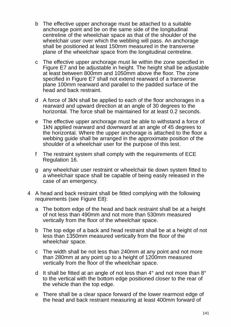
141
b The effective upper anchorage must be attached to a suitableanchorage point and be on the same side of the longitudinalcentreline of the wheelchair space as that of the shoulder of thewheelchair user over which the webbing will pass. An anchorageshall be positioned at least 150mm measured in the transverseplane of the wheelchair space from the longitudinal centreline.
c The effective upper anchorage must lie within the zone specified inFigure E7 and be adjustable in height. The height shall be adjustableat least between 800mm and 1050mm above the floor. The zonespecified in Figure E7 shall not extend rearward of a transverseplane 100mm rearward and parallel to the padded surface of thehead and back restraint.
d A force of 3kN shall be applied to each of the floor anchorages in arearward and upward direction at an angle of 30 degrees to thehorizontal. The force shall be maintained for at least 0.2 seconds.
e The effective upper anchorage must be able to withstand a force of1kN applied rearward and downward at an angle of 45 degrees tothe horizontal. Where the upper anchorage is attached to the floor awebbing guide shall be arranged in the approximate position of theshoulder of a wheelchair user for the purpose of this test.
f The restraint system shall comply with the requirements of ECERegulation 16.
g any wheelchair user restraint or wheelchair tie down system fitted toa wheelchair space shall be capable of being easily released in thecase of an emergency.
4 A head and back restraint shall be fitted complying with the followingrequirements (see Figure E8):
a The bottom edge of the head and back restraint shall be at a heightof not less than 490mm and not more than 530mm measuredvertically from the floor of the wheelchair space.
b The top edge of a back and head restraint shall be at a height of notless than 1350mm measured vertically from the floor of thewheelchair space.
c The width shall be not less than 240mm at any point and not morethan 280mm at any point up to a height of 1200mm measuredvertically from the floor of the wheelchair space.
d It shall be fitted at an angle of not less than 4° and not more than 8°to the vertical with the bottom edge positioned closer to the rear ofthe vehicle than the top edge.
e There shall be a clear space forward of the lower rearmost edge ofthe head and back restraint measuring at least 400mm forward of
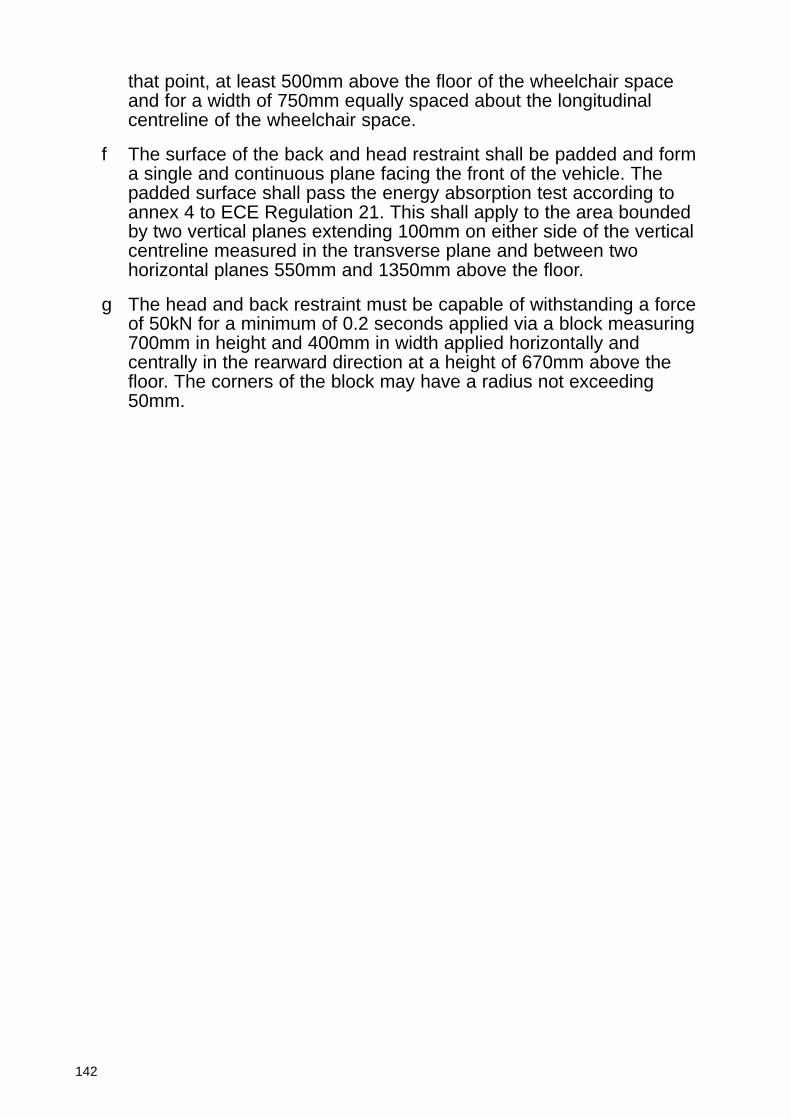
142
that point, at least 500mm above the floor of the wheelchair spaceand for a width of 750mm equally spaced about the longitudinalcentreline of the wheelchair space.
f The surface of the back and head restraint shall be padded and forma single and continuous plane facing the front of the vehicle. Thepadded surface shall pass the energy absorption test according toannex 4 to ECE Regulation 21. This shall apply to the area boundedby two vertical planes extending 100mm on either side of the verticalcentreline measured in the transverse plane and between twohorizontal planes 550mm and 1350mm above the floor.
g The head and back restraint must be capable of withstanding a forceof 50kN for a minimum of 0.2 seconds applied via a block measuring700mm in height and 400mm in width applied horizontally andcentrally in the rearward direction at a height of 670mm above thefloor. The corners of the block may have a radius not exceeding50mm.
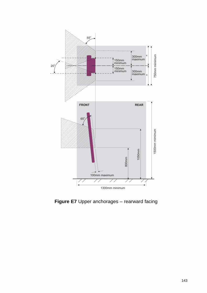
143
150mmminimum
1300mm minimum
FRONT REAR
65o
==
150mmminimum
20o
55o
100mm maximum
300mmmaximum
300mmmaximum
750m
m m
imim
um
1500m
m m
imim
um
800m
m 1050m
m
Figure E7 Upper anchorages – rearward facing
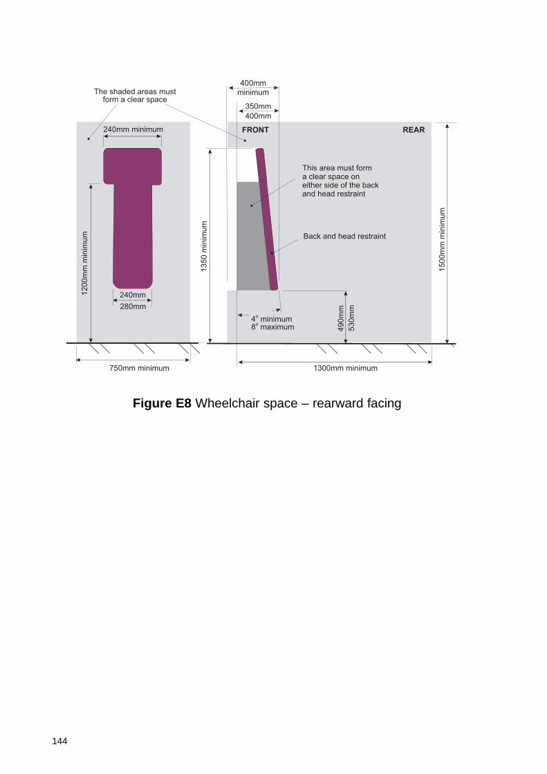
144
The shaded areas mustform a clear space
240mm minimum
400mm
350mm
280mm
FRONT REAR
This area must form a clear space on either side of the back and head restraint
Back and head restraint
49
0m
m
4o minimum
8o maximum
13
50
min
imu
m
15
00
mm
min
imu
m
12
00
mm
min
imu
m
1300mm minimum750mm minimum
minimum
400mm
240mm
53
0m
m
Figure E8 Wheelchair space – rearward facing