the science of mixing water storage tanks operations/tms...the science of mixing water storage tanks...
TRANSCRIPT

2009 Red Valve Co. / Tideflex Technologies. All rights reserved.
The Science of Mixing Water Storage Tanks
Presented by:
Jason Barrett, Flomec Inc.
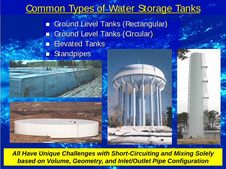
Ground Level Tanks (Rectangular) Ground Level Tanks (Circular) Elevated Tanks Standpipes
Common Types of Water Storage Tanks
All Have Unique Challenges with Short-Circuiting and Mixing Solely based on Volume, Geometry, and Inlet/Outlet Pipe Configuration

1) Minimize Short-Circuiting and Stagnant Areas (SEPARATE INLET AND OUTLET PIPE) 2) Achieve Complete Mixing During Fill Cycle (MIXING TIME LESS THAN FILL TIME) 3) Achieve Adequate Turnover to Minimize Water Age (FLUCTUATE LEVELS)
** MAINTAIN ADEQUATE DISINFECTANT RESIDUAL **
How to Maintain Water Quality in Reservoirs
COMBINATION OF MIXING SYSTEM DESIGN AND TURNOVER/FLUCTUATION OF THE TANK
DESIGN
OPERATIONS
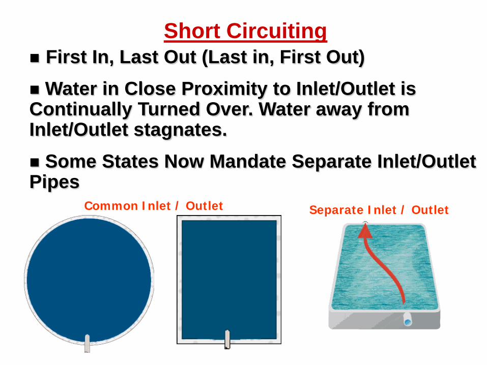
Short Circuiting First In, Last Out (Last in, First Out) Water in Close Proximity to Inlet/Outlet is Continually Turned Over. Water away from Inlet/Outlet stagnates. Some States Now Mandate Separate Inlet/Outlet Pipes
Common Inlet / Outlet Separate Inlet / Outlet
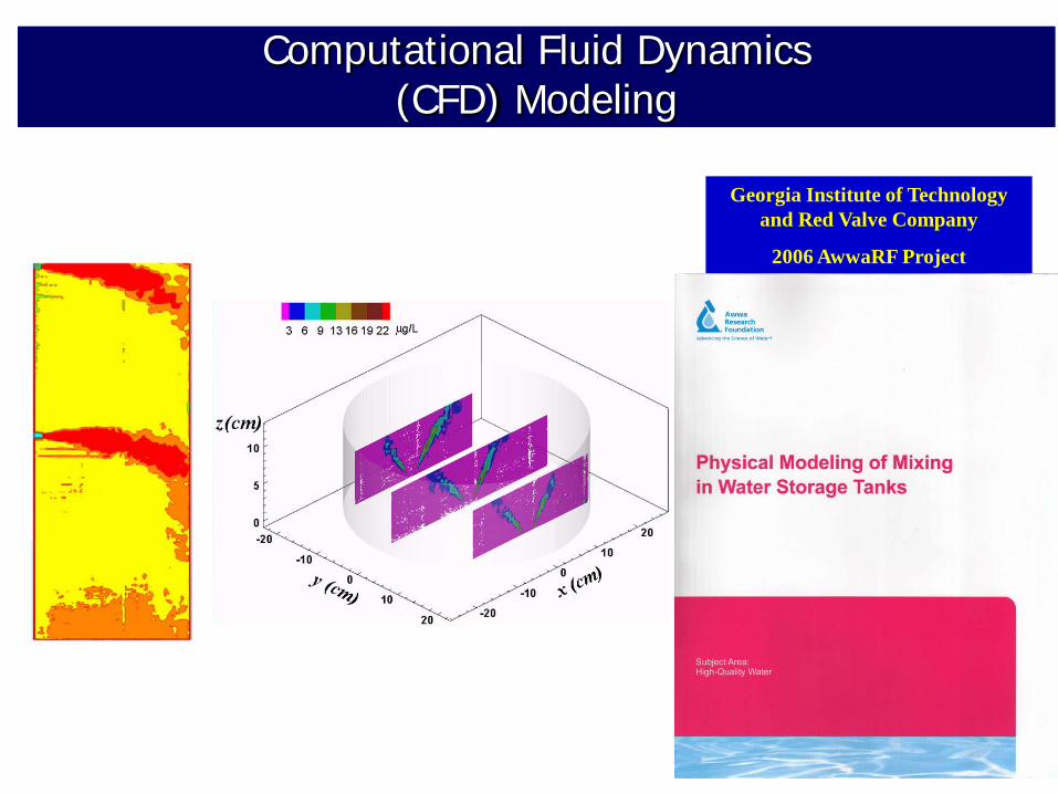
Computational Fluid Dynamics (CFD) Modeling
Georgia Institute of Technology and Red Valve Company
2006 AwwaRF Project

CAUTION When Separating Inlet and Outlet
• Must Understand the Circulation Patterns in Order to Know Where Mixing Happens Last. Outlet(s) Would Go in Those Locations
• Getting Inlet and Outlet “As Far Apart As Possible” is Often the Wrong Assumption
• Circulation Patterns Change with Temperature Differences Between Inlet and Tank Water

Multiple Inlet Ports Result in Up to 50% Faster Mixing Compared to Single Inlets
Single Shell Penetration 5-Port TMS
Animations courtesy of :
Los Angeles Department of Water & Power Northwest Hydraulic Consultants
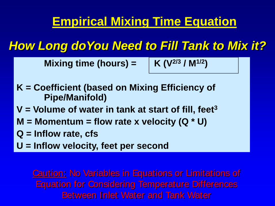
Mixing time (hours) = K (V2/3 / M1/2) K = Coefficient (based on Mixing Efficiency of Pipe/Manifold) V = Volume of water in tank at start of fill, feet3 M = Momentum = flow rate x velocity (Q * U)
Q = Inflow rate, cfs U = Inflow velocity, feet per second
Empirical Mixing Time Equation
How Long doYou Need to Fill Tank to Mix it?
Caution: No Variables in Equations or Limitations of Equation for Considering Temperature Differences
Between Inlet Water and Tank Water

Mixing Time Equation is Limited to Same Inlet and Tank Water Temperature
■ Mixing Time Equation May Grossly Underestimate Fill Time Required to Mix
■ Jet Must Reach Water Surface to Mix Tank
■ Mixing Will Only Occur to Terminal Rise Height (TRH) of Jet
■ Below TRH - Adequate Mixing, Temperature, and Residual
■ Above TRH – No Mixing, Water Age Continually Increases With Each Fill & Draw Cycle, Lose Residual
■ Have No Idea of Potential Problem Even if Sampling Outside of Tank
2oF Colder Inlet Water

Effect Of Colder Inlet Water on Mixing in Reservoir
INLET 4° F COLDER Will Short-Circuit Even with Separate Outlet Pipe
Will Not Mix Tank Regardless How Long it is Filled
ISOTHERMAL
Will Not Short-Circuit with Separate Outlet Pipe
Will Mix Tank IF Fill Long Enough
CFD Model – 2.5MG Reservoir (120’ Dia. X 30’ SWD)

Temperature and Cl2 Residual Data 4MG Steel Reservoir – Northern California
Temperature Variation Thru Depth (Thermocline) Indicates Incomplete Mixing and Warns of Potential Water Quality Problems
Warning: Samples Taken Just Outside of Tank Would Never Show the W.Q. Problem
Thermocline
Water Quality Problem

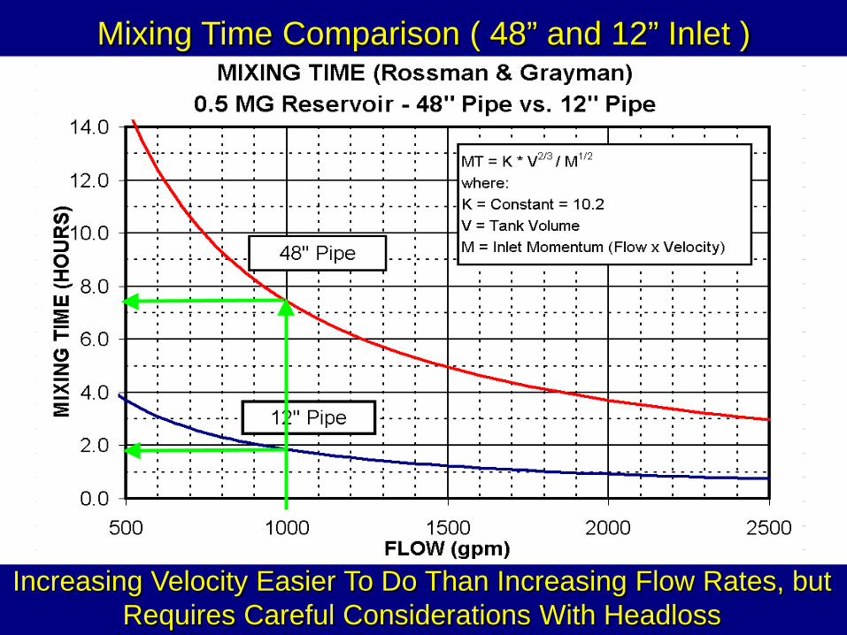
Mixing Time Comparison ( 48” and 12” Inlet )
Increasing Velocity Easier To Do Than Increasing Flow Rates, but Requires Careful Considerations With Headloss

Greener than Green. Passive. Uses energy source inherent to distribution systems – differential pressure
All TMS Configurations are CFD and/or Scale Modeled and Field Validated for Every Tank Style
Achieves Separate Inlet and Outlet on a Single Manifold Pipe Achieves Complete Mixing with Variable Orifice Tideflex Inlet Nozzles No Maintenance - No Mechanical Parts NSF61 Certified Valves Connected to Inlet/Outlet Pipe – No Additional Tank Penetrations
Required Easy Retrofit (dry or wet installation) Complete System Design At Least 30 year life
Tideflex Mixing System (TMS) Features

TMS for Circular Reservoirs

OUTLETS
Use of Tideflex for Inlet/Outlet Separation on Single Manifold Pipe
INLETS
DUCKBILL INLET NOZZLES
OUTLET CHECK VALVES
OLD 2-PIPE SYSTEM
DUCKBILL MANIFOLD PIPE

PROBLEM
TIDEFLEX “Duckbill” Check Valves
SOLUTION
Overflow Pipe Protection Overflow Security
Valve (OSV)
PROBLEM
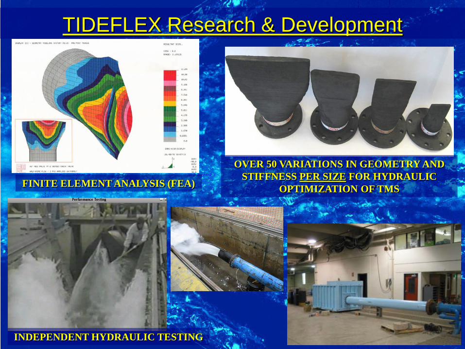
TIDEFLEX Research & Development
FINITE ELEMENT ANALYSIS (FEA)
INDEPENDENT HYDRAULIC TESTING
OVER 50 VARIATIONS IN GEOMETRY AND STIFFNESS PER SIZE FOR HYDRAULIC
OPTIMIZATION OF TMS

Optimized Hydraulics of Tideflex
Tideflex Inlet Nozzles Maximize Jet Velocity at ALL Flow Rates Compared to Fixed-Diameter Pipe
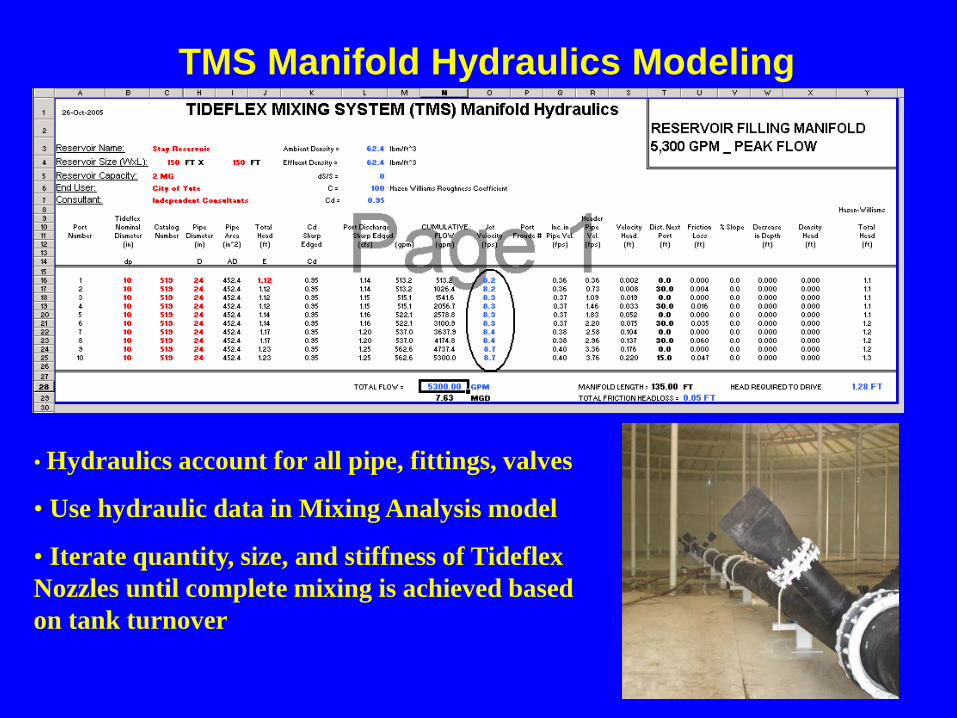
TMS Manifold Hydraulics Modeling
• Hydraulics account for all pipe, fittings, valves
• Use hydraulic data in Mixing Analysis model
• Iterate quantity, size, and stiffness of Tideflex Nozzles until complete mixing is achieved based on tank turnover
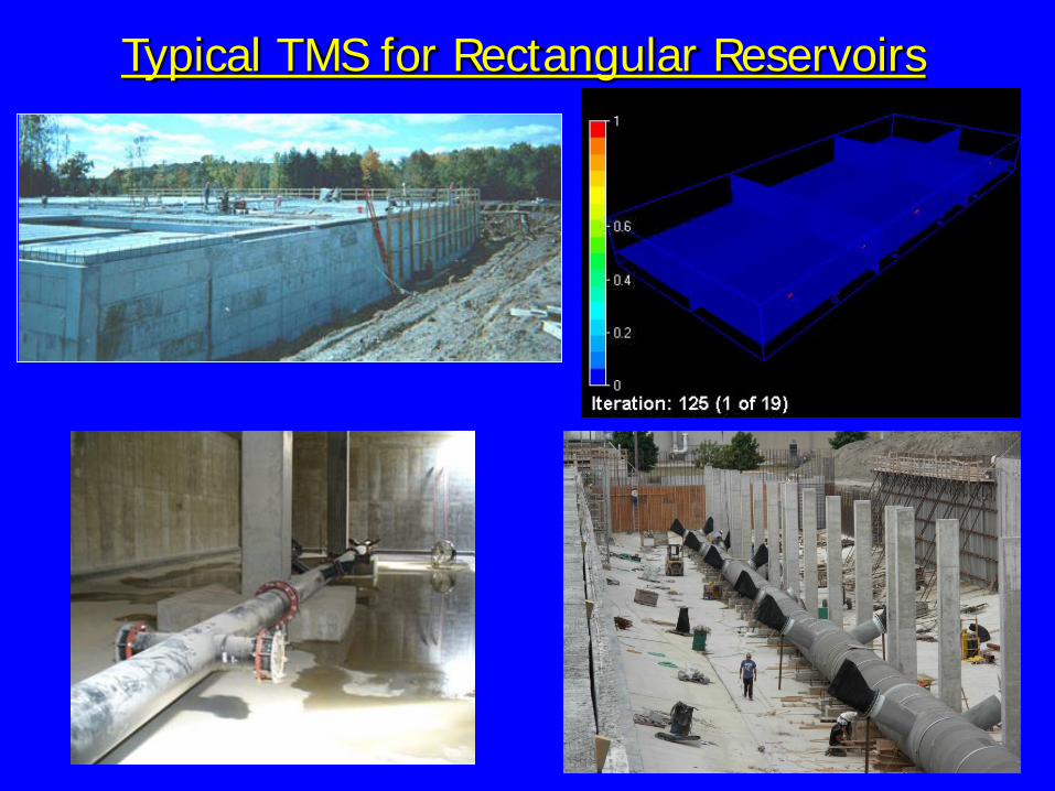
Typical TMS for Rectangular Reservoirs
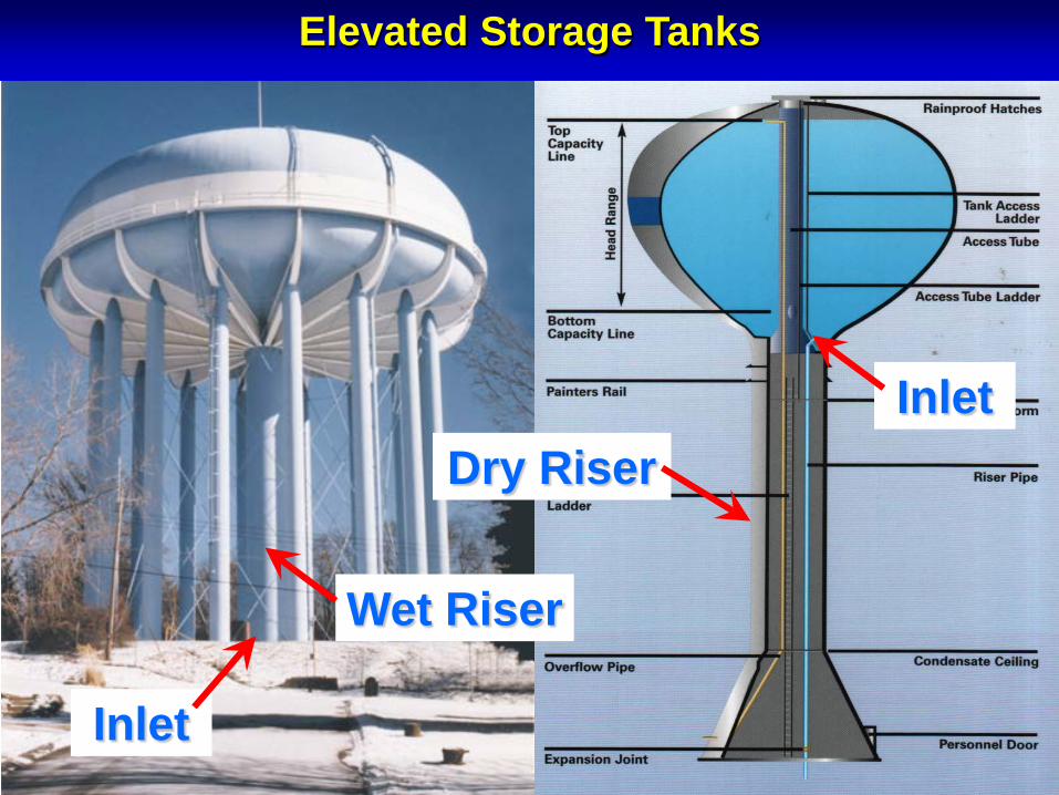
Wet Riser
Inlet
Dry Riser Inlet
Elevated Storage Tanks
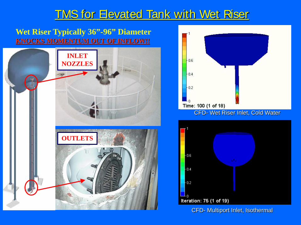
TMS for Elevated Tank with Wet Riser
INLET NOZZLES
OUTLETS
Wet Riser Typically 36”-96” Diameter KNOCKS MOMENTUM OUT OF INFLOW!!
CFD- Wet Riser Inlet, Cold Water
CFD- Multiport Inlet, Isothermal

TMS for Pedesphere, Hydropillar and Composite Elevated Tanks
Tideflex Inlet Nozzles
Waterflex Outlet Valves
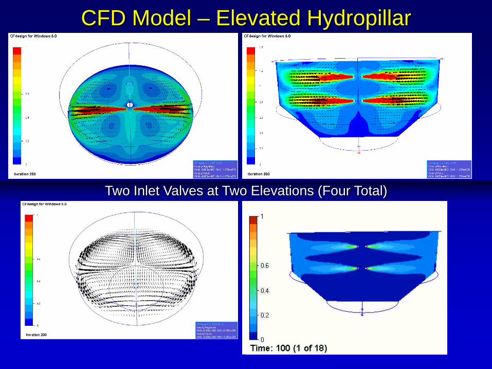
CFD Model – Elevated Hydropillar
Two Inlet Valves at Two Elevations (Four Total)

Sampling 1.5MG and 2MG Elevated Tanks with and without TMS - McKinney, TX
2MG Composite Elevated with TMS
2MG Composite Elevated with TMS
1.5MG Composite Elevated without TMS
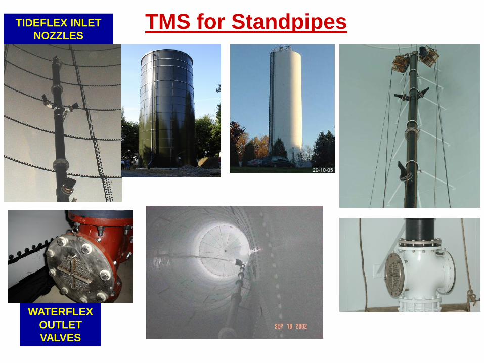
TMS for Standpipes TIDEFLEX INLET NOZZLES
WATERFLEX OUTLET VALVES
2008 Red Valve Company/Tideflex Technologies. All rights reserved
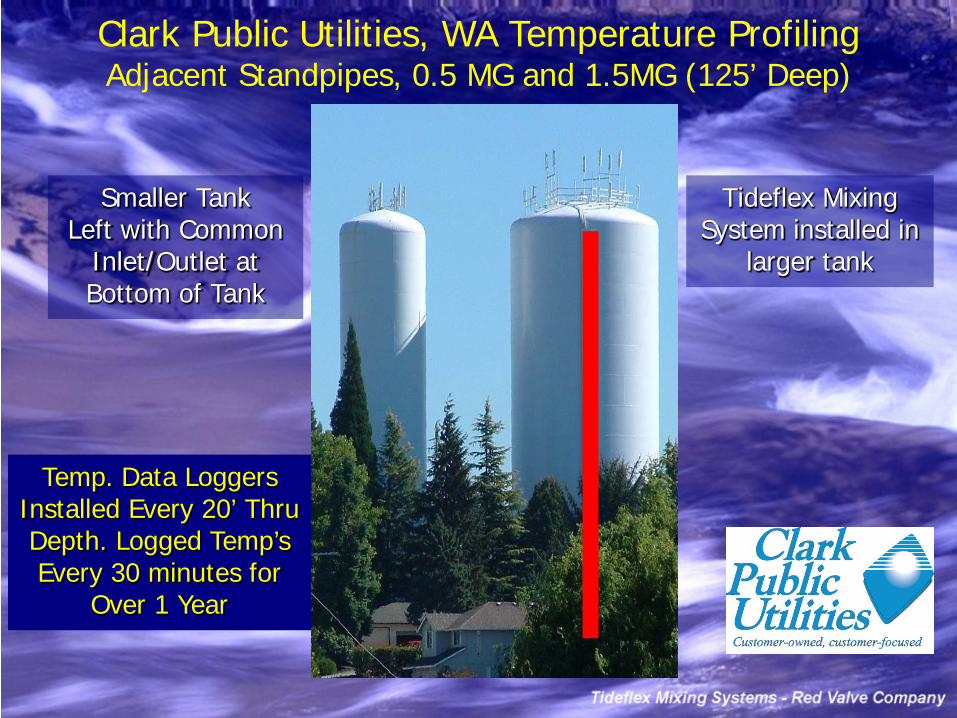
Clark Public Utilities, WA Temperature Profiling Adjacent Standpipes, 0.5 MG and 1.5MG (125’ Deep)
Tideflex Mixing System installed in
larger tank
Smaller Tank Left with Common
Inlet/Outlet at Bottom of Tank
Temp. Data Loggers Installed Every 20’ Thru Depth. Logged Temp’s Every 30 minutes for
Over 1 Year

Temperature vs. Depth Data
7/12/03
60
62
64
66
68
70
72
74
76
10 30 50 70 90
0.5 MG 1.5 MG
8/1/03
60
62
64
66
68
70
72
74
76
10 30 50 70 90
0.5 MG 1.5 MG
Without TMS
Without TMS
With TMS With TMS
Stratification Gets Worse in Smaller Tank from July to August
Stratification Eliminated in Larger Tank with Mixing System
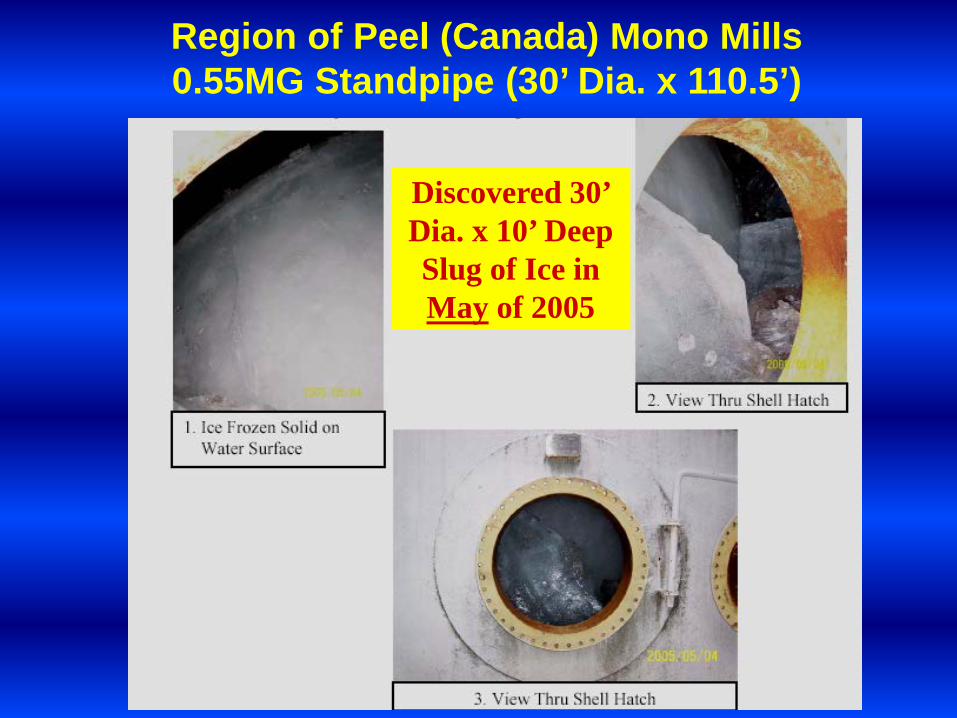
Region of Peel (Canada) Mono Mills 0.55MG Standpipe (30’ Dia. x 110.5’)
Discovered 30’ Dia. x 10’ Deep Slug of Ice in May of 2005

Region of Peel Mono Mills 0.55MG Standpipe (30’ Dia. X 110.5’)
Ice removal took 2 weeks and $27,000

Region of Peel Mono Mills 0.55MG Standpipe Installed TMS
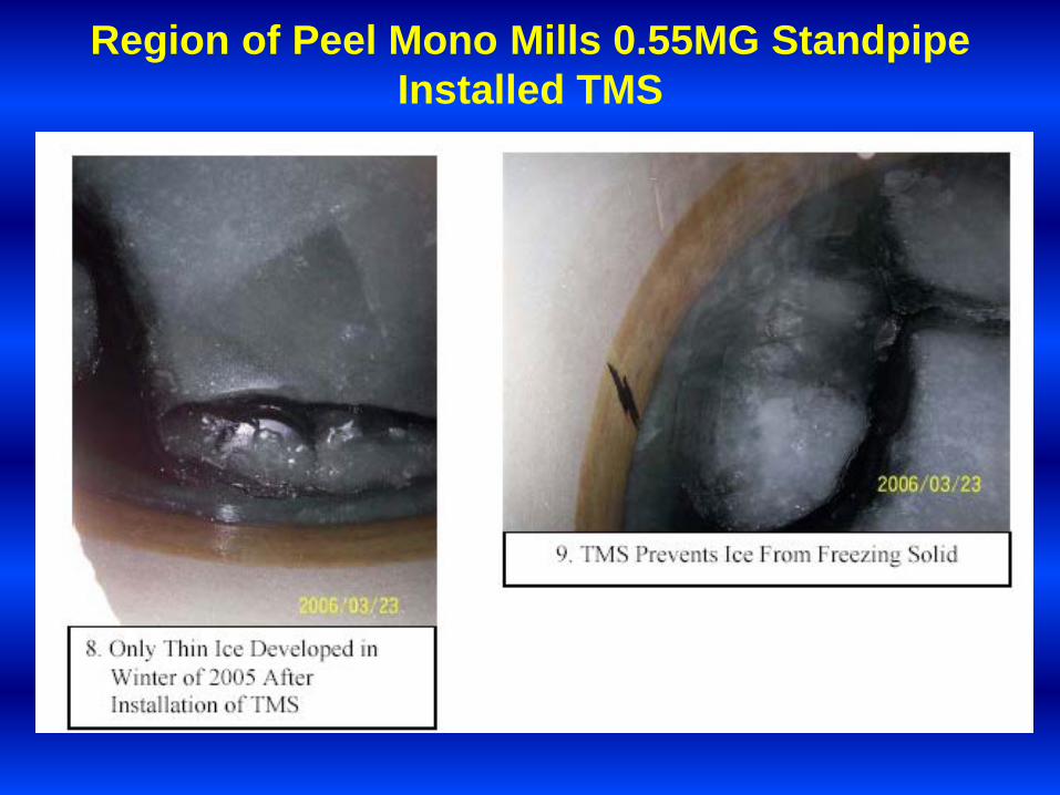
Region of Peel Mono Mills 0.55MG Standpipe Installed TMS

Consider: External Energy Source Capital Cost Operational Cost No Impact on Water Age No Separation of Inlet/Outlet Safety? Electric & Water Maintenance Roof Reinforcement Req’d Another Penetration for Wires Interfere with Cathodic Protection Contamination? Vandalism NSF Certified? Limited Installations Limited Testing and Field Validation
Mechanical Mixers (Electric and Solar Powered)
Simply put, mechanical mixers add another source of energy to the tank to mix. However, there is already a built-in source of energy –
differential pressure. Tanks need to fill and draw to minimize water age. The differential pressure
present during the fill can mix the tank with properly designed mixing system.

Complete System Design and Hydraulic Analysis