theme: (bio)medical precision design principles in
TRANSCRIPT

MIKRONIEK IS A PUBLICATION OF THE DUTCH SOCIETY FOR PRECISION ENGINEERING – WWW.DSPE.NL
PROFESSIONAL JOURNAL ON PRECISION ENGINEERING2021 (VOL. 61) ISSUE 4
THEME: (BIO)MEDICAL PRECISION DESIGN PRINCIPLES IN COLLIMATOR AT 35 G MOTION FEEDFORWARD TUNING FOR HYSTERETIC PIEZO ACTUATORS THE NEW NORMAL – REPORT OF EUSPEN’S VIRTUAL INTERNATIONAL CONFERENCE 2021

ISSUE 4 2021
IN THIS ISSUEPUBLICATION INFORMATION
ObjectiveProfessional journal on precision engineering and the official organ of DSPE, the Dutch Society for Precision Engineering. Mikroniek provides current information about scientific, technical and business developments in the fields of precision engineering, mechatronics and optics. The journal is read by researchers and professionals in charge of the development and realisation of advanced precision machinery.
PublisherDSPEJulie van StiphoutHigh Tech Campus 1, 5656 AE EindhovenPO Box 80036, 5600 JW [email protected], www.dspe.nl
Editorial boardProf.dr.ir. Just Herder (chairman, Delft University of Technology), Servaas Bank (VDL ETG), B.Sc.,ir.ing. Bert Brals (Sioux Mechatronics),Maarten Dekker, M.Sc. (Philips), Otte Haitsma, M.Sc. (Demcon), dr.ir. Jan de Jong (University of Twente), ing. Ronald Lamers, M.Sc. (Thermo Fisher Scientific), Erik Manders, M.Sc. (Philips Innovation Services),dr.ir. Pieter Nuij (MaDyCon), dr.ir. Gerrit Oosterhuis (VDL ETG), Maurice Teuwen, M.Sc. (Janssen Precision Engineering)
EditorHans van Eerden, [email protected]
Advertising canvasserGerrit Kulsdom, Sales & Services+31 (0)229 – 211 211, [email protected]
Design and realisationDrukkerij Snep, Eindhoven+31 (0)40 – 251 99 29, [email protected]
SubscriptionMikroniek is for DSPE members only. DSPE membership is open to institutes, companies, self-employed professionals and private persons, and starts at € 80.00 (excl. VAT) per year.
Mikroniek appears six times a year.© Nothing from this publication may be reproduced or copied without the express permission of the publisher.
ISSN 0026-3699
26
32
The cover image (featuring the construction of a CT-scanner collimator) is courtesy of Philips Engineering Services. Read the article on page 15 ff.
FEATURES
04 EDITORIALGeert Hellings, advisor and former managing director of Mikrocentrum, on the evolution towards the International Precision Fair 2.0.
42 TAPPING INTO A NEW DSPE MEMBER’S EXPERTISE
Exakt Fijnmechanika – where even precise is not accurate enough.
43 UPCOMING EVENTSIncluding: Precision Fair 2021.
44 ECP2 COURSE CALENDAROverview of European Certified Precision Engineering courses.
45 NEWSIncluding: 4th Gas Bearing Workshop welcomes Switzerland.
THEME: (BIO)MEDICAL PRECISION
05Self-propelling steeerable needleThe bio-inspired design of a needle that has potential medical applications including localised therapeutic drug delivery and tissue sample removal (biopsy).
09The next step of Project MARCHA Delft student team uses biomechatronics technology to enable dynamic walking for people with paraplegia.
15Collimator design for 35 gWim van der Hoek’s design principles applied in medical systems engineering at Philips.
18Stent analysisFinite-element studies of crimping and expanding stents that are used to open blood vessels.
24Stacking orthopaedic precision productsElectron beam melting as an alternative for laser-driven additive manufacturing.
26Control of hysteretic piezo actuatorsA new hysteresis modelling approach that allows for a straightforward feedforward controller that can be manually tuned.
32Event report – DSPE “Precision Engineering in Vacuum” Knowledge DayVacuum challenges in high-tech system design, ranging from analysis and design to engineering and calibration.
35Event report – euspen’s Virtual International Conference 2021Today’s “new normal” was reflected by the virtual character of the event and by a keynote: complex data as the new normal in precision engineering.
39Event preview – DeburringEXPO 2021Trends in deburring and precision surfaces.
› Inspirational live/online presentations by invited international speakers including presentations from adjacent applications areas like bio-inspired robotics, photonics and more.
› Opportunity to jointly watch the presentations (incl. Q&A), meet/network and exchange ideas in a pleasant atmosphere including a BBQ (all depending on COVID rules in September).
› For members of DSPE, Brainport Industries, CGM and MSKE only.
CALL FOR ABSTRACTSDeadline short abstract submission: February 1, 2018
CONFERENCEON PRECISIONMECHATRONICS
YOUR PRECISION PORTAL
www.dspe-conference.nl
MEET YOUR PEERS IN PRECISION MECHATRONICS
Sangbae Kim
Professor of Mechanical Engineering andDirector of Biomimetic Robotics lab Massachusetts Institute of Technology
Patrick Naulleau
Senior Scientist and Director of The Center for X-Ray Optics at Lawrence Berkeley National Laboratory
Maarten van Andel
Director of Fontys University of Applied Natural Sciences
Theresa Spaan-Burke
Innnovation Director IBS Engineering
Hajime Asama
Professor Robotics University of Tokyo
Auke Ijspeert
Professor at the EPFL (Swiss Federal Institute of Technology at Lausanne), head of Biorobotics Laboratory
Tjin Swee Chuan
Professor at the Nanyang Technological University Singapore, Co-Director The Photonics Institute Singapore
DSPE meets the worldSpecial edition
Registration is open!
14 & 15 September 2021Location: EindhovenLocation: Historical Flights Gilze Rijen
nr 4 2021 MIKRONIEK 3
EDITORIAL
This year will see the 20th edition of the Precision Fair. In fact, this anniversary should already have been celebrated in 2020, but for obvious reasons the fair had to be postponed by a year. For the first time, the Brabanthallen in ’s-Hertogenbosch (NL) will be the venue. It marks a good time to look back and to look forward.
It all started with research undertaken in 1998 by consultancy firm Berenschot into ‘the importance and possibilities of precision technology in the Netherlands’. This was supported by TNO, Mikrocentrum and of course DSPE (then still NVPT), and resulted in the IOP (Innovation-oriented Research Programme) Precision Technology. Triggered by the promising start of the Plastics Fair (Kunststoffenbeurs) in 1999, Henny Spaan suggested Mikrocentrum to organise a Precision Fair (Precisiebeurs) as well. The first edition was in October 2001 and the fair has grown gradually to its present size.
Due to various outstanding companies, precision technology has undergone an incredible development in the Netherlands over the last twenty years. Clearly, all of these companies operate and compete in an increasingly international environment. What is the impact of this on trade fairs? Most likely, the Precision Fair will also have to adapt, including becoming more international, although there are already a number of international exhibitors and visitors at present. An increased international focus was already topic of discussion about a decade ago.
In 2012, I visited CERN, the well-known particle accelerator in Geneva (CH) that became world famous in 2013 for its discovery of the Higgs boson. As a result, a large CERN delegation visited the Precision Fair in 2012, joined in subsequent years by several other Big Science organisations. This all resulted in close cooperation with various Big Science projects, with several Dutch companies benefitting. As an example, in 2020 the revenue of Dutch companies involved with CERN exceeded the annual funding of CERN by the Dutch government for the first time. Hopefully, this will be repeated if the Einstein telescope (for gravitational waves) is realised in the south of the Netherlands.
How might things develop over coming years? I personally believe that this really is the moment to transform the Precision Fair from a mainly local trade fair into a truly international trade fair. In fact, the Precision Fair is already unique, not just in the Netherlands, but also abroad. Other trade fairs include precision technology topics, but probably none of them to the degree present at the Precision Fair. In general, we should not fear international competition, but embrace it.
The larger venue of the Precision Fair, the introduction in 2019 of an annually changing partner country, and close cooperation with international organisations like euspen and DSPE will all facilitate international expansion. In addition, Mikrocentrum’s experience, the existing involvement of precision technology companies, and the spirit of close cooperation over the entire Dutch precision technology sector could be the driving forces in achieving this. Perhaps travel restrictions may still limit such ambitions in 2021, but certainly in the next few years the Precision Fair could further increase its relevance to a level uncommon for the Netherlands.
I would love to see a truly international Precision Fair become a reality in the near future.
Geert HellingsAdvisor and former managing director Mikrocentrum (2003-2021)
INTERNATIONAL PRECISION FAIR 2.0
4 MIKRONIEK nr 4 2021

THEME – BIO-INSPIRED DESIGN OF MEDICAL INSTRUMENTS
SELF-PROPELLING AND STEEERABLE
AUTHOR’S NOTE
This article was based on an interview with Paul Breedveld, professor of Minimally Invasive Surgery & Bio-Inspired Technology and chair of the Bio-Inspired Technology (BITE) research group in the department of Biomechanical Engineering at Delft University of Technology (NL), and on publications from his group, in particular the Ph.D. thesis by Marta Scali [1].
The Delft-based Bio-Inspired Technology (BITE) research group works on the development of innovative technical systems and instruments for minimally invasive surgery and other medical interventions, drawing inspiration from extraordinary biological mechanisms. The group collaborates with academic hospitals, biology groups, veterinary hospitals and companies, and has already brought products to the clinic. BITE output includes surgical knives, tissue puncturing devices, and steerable needles and instruments.
One example is the LaproFlex steerable laparoscopic instrument with ergonomic axial handle, which is now being marketed by spin-off company DEAM (Figure 1). In 2019, the first operation (gynaecological) was performed using the instrument. The technology behind the instrument was already described in Mikroniek in 2007 [1]. The LaproFlex has a flexible tip, enabled by an ingenious steering system based on the anatomy of an octopus’ tentacle, the so-called cable ring mechanism, which ensures
The design of a self-propelling, steerable needle was inspired by a wasp’s ovipositor, a thin, flexible needle-like structure used for laying eggs into larvae hidden inside fruit or wood. The needle’s potential medical applications include localised therapeutic drug delivery and tissue sample removal (biopsy). The instrument consists of three or more wires that are moved back and forth inside tissue sequentially. Through friction, a net pulling motion of the tissue towards the actuation unit is generated, resulting in the instrument moving forward inside the tissue. Different sequences of wire actuation can achieve either straight or curved trajectories.
Figuur 5: Doorsnede van een inktvistentakel.
Figuur 6: Doorsnede van het kabelkransmechanisme.
Figuur 5: Doorsnede van een inktvistentakel.
Figuur 6: Doorsnede van het kabelkransmechanisme.
1a 1b
The LaproFlex steerable laparoscopic instrument.(a) Concept of the patented cable ring mechanism, shown in cross-section as two halves that have been pulled apart for clarity [2].(b) Commercial version marketed by DEAM, which developed the ergonomic axial handle.
that scissors or a grasper, for example, can be steered in any direction.
Wasp needle-like structureMore recent research on steerable instruments [1] was inspired by the wasp ovipositor, a needle-like structure used by the female parasitoid wasp to drill into wood or fruit and deposit eggs inside living hosts such as larvae. The WASP project was started in 2015, funded by the Netherlands Organization for Scientific Research (NWO), as part of the iMIT programme aimed at developing interactive multi-interventional tools.
The WASP project was focused on medical needles that have to reach their target deep inside a patient’s body with high precision. This requires a flexible, steerable needle that can follow complex curved trajectories through complex solid organs while avoiding sensitive structures, such as blood vessels, located along the trajectory between the insertion point and the target site.
nr 4 2021 MIKRONIEK 5

THEME – BIO-INSPIRED DESIGN OF MEDICAL INSTRUMENTS
The wasp’s ovipositor is a needle-like structure composed of three longitudinal, interlocking segments that can be actuated individually and independently of each other by musculature that is located in the abdomen of the insect. The propagation of the ovipositor through a substrate is achieved by a push-pull mechanism, in which one of the elements is pushed while the other two are pulled. In this way, the wasp steers the ovipositor along curved trajectories inside different substrates without a need for rotatory motion or global axial push. Inspired by the anatomy and the steering mechanism of this needle-like structure, the aim was to develop an ultra-thin, self-propelled, steerable needle.
DesignIn the first design ([3], the second item), superelastic nickel NiTi wires were used for the segments. Interlocking these turned out to be challenging. In a wasp, the ovipositor segments are interlocked by a jigsaw-puzzle-like structure, which allows them to slide along each other and thus avoid separation. Miniaturisation of such a complex interlocking mechanism was not feasible from a manufacturing perspective.
Therefore, the designers took a step away from nature and decided instead to interlock the wires externally, using a ring with holes through which the wires are fed (Figure 2). The ring was given a flower shape to reduce resistance during propulsion through the substrate. The ring has a central hole to which the central wire is glued and six peripheral holes through which the six other wires can slide back and forth. The first prototype had a diameter of 1.2 mm at the tip and 0.75 mm along the body, while the NiTi wires were 0.25 mm in diameter and 160 mm long, and the flower-shaped ring was 2.0 mm long.
Forward motion Each proximal end of the six movable wires is connected to a miniature stepper motor, in which a leadscrew-slider mechanism converts rotational motion into linear motion.
The needle is moved forward through the substrate firstly by pushing the six wires one by one (or two by two), followed by pulling on all six wires simultaneously, which advances the interlocking ring and the central wire into the substrate.
Figure 3 shows the forces acting on the needle during the forward motion. In the first phase, the sum of the dynamic friction force (Fwire,dyn) and the cutting force (Fwire,cut) on the wire(s) moving forward should be smaller than (or equal to) the static friction force on the stationary wires and the interlocking ring (Fwire,stat and Fring,stat , respectively). In the second phase, the ring moves forward if the cutting and the dynamic friction forces on the advancing inter-locking ring (Fring,cut and Fring,dyn, respectively) are smaller than (or equal to) the static friction force between the wires and the substrate (Fwire,stat).
2a 2b 2c
First design of an ovipositor-inspired needle.(a) Cross-section of the flower-shaped ring, with a central hole to which the central wire is glued and six peripheral holes through which
the six other wires can slide back and forth.(b) Initial position of the wires. (c) Prototype, showing the tip of the needle with the ring, and some of the wires moved forward.
3b
3a
Schematic representation of the two-phase forward motion mechanism of a needle with six peripheral wires and one central wire. The thick arrow represents the motion of the wires and the ring. See text for further explanation.(a) First, one wire is pushed forward at a time (green). (b) After all six peripheral wires have been moved forward one by one,
they are pulled back simultaneously, resulting in advancement of the ring and the central wire inside the substrate.
6 MIKRONIEK nr 4 2021
THEME – BIOMECHATRONICS TECHNOLOGY ENABLING DYNAMIC WALKING FOR PEOPLE WITH PARAPLEGIA
THE NEXT STEP OF PROJECT MARCH
EDITORIAL NOTE
This article was based on information provided by Project MARCH, in particular a series of blogs about the technical design.
www.projectmarch.nl
IntroductionEach year, a new Project MARCH team is composed from Delft University of Technology (TU Delft) students of various backgrounds and years of study. The team then takes from September until the end of the following summer to develop a new exoskeleton. Every time, their design choices and project development are thoroughly documented, with a lot of attention paid to the handover of the project from one team to the next. Recently, Project MARCH settled in its new location in RoboValley, “a future-of-work fieldlab where robot developments and the study of social processes can occur simultaneously”, on the TU Delft campus.
Project MARCH VI’s goal was to develop an entirely new exoskeleton, with which the team’s pilot could walk a route through the city of Delft in a dynamic way. ‘Dynamic’ here means that the movement of the exoskeleton is controlled using live information about the environment, instead of pre-programmed movements. On this route, the pilot, who is a person with paraplegia, will come across various obstacles such as bridges, pavers and ramps.
Project MARCH, a non-profit student team from Delft University of Technology (NL), is driven by the vision that using exoskeleton technology can improve the quality of life for people with paraplegia. An exoskeleton is a motorised robotic harness that enables them to stand up and walk again. Each year, Project MARCH develops a new version, to both stimulate technological innovation in exoskeletons and challenge students to think of new solutions. The sixth team’s goal was to develop an entirely new exoskeleton with which the team’s pilot could walk a route through the city of Delft in a dynamic way. This was achieved last month.
The design of MARCH VI (Figure 1) was presented March 2021; see the video [V1]. The biggest challenges for this sixth version were to provide the exoskeleton with dynamic walking control, improve its user-friendliness and make it suitable for outdoor use. Some of the main design choices are highlighted below.
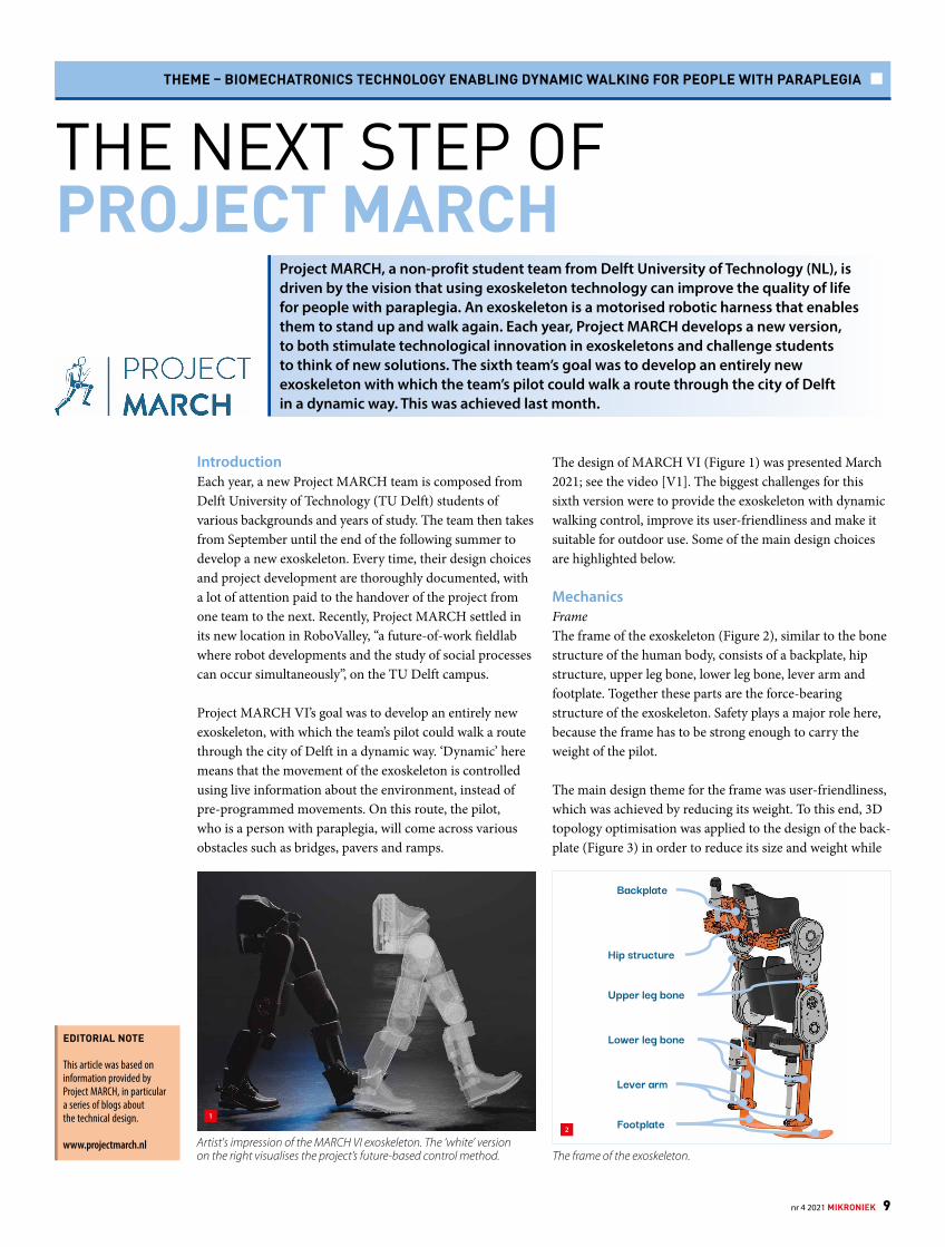
MechanicsFrameThe frame of the exoskeleton (Figure 2), similar to the bone structure of the human body, consists of a backplate, hip structure, upper leg bone, lower leg bone, lever arm and footplate. Together these parts are the force-bearing structure of the exoskeleton. Safety plays a major role here, because the frame has to be strong enough to carry the weight of the pilot.
The main design theme for the frame was user-friendliness, which was achieved by reducing its weight. To this end, 3D topology optimisation was applied to the design of the back-plate (Figure 3) in order to reduce its size and weight while
The frame of the exoskeleton.
Backplate
Hip structure
Upper leg bone
Lever arm
Footplate
Lower leg bone
Artist's impression of the MARCH VI exoskeleton. The ‘white’ version on the right visualises the project’s future-based control method.
1
2
nr 4 2021 MIKRONIEK 9

THEME – BIOMECHATRONICS TECHNOLOGY ENABLING DYNAMIC WALKING FOR PEOPLE WITH PARAPLEGIA
maintaining its main function, i.e. to safely absorb all forces that the pilot and various attached parts/modules exert on it.
Another user-friendly design upgrade was the added hinge that allows an exoskeleton leg to be rotated out in order to facilitate the pilot’s transfer from wheelchair to exoskeleton (and vice versa). Naturally, after the transfer, the leg has to be turned back in and the hinge secured. A design study to find a safe solution resulted in two concepts: the lever latch and the quick-release. In both concepts, the frame is made up of two parts in which the edges are shaped to fit neatly together, like two parts of a whole, with large overlapping surfaces.
In the quick-release concept, the hinge is fixated with a pin that runs through both frame parts. A clamping mechanism can be added to this pin to not only block the rotation, but also to clamp the frame pieces together to prevent wiggling. In the other concept, a lever latch on top of the frame is used to pull these surfaces together and fixate the hinge. Upon evaluation, the quick-release system (Figure 4) proved to be safer, more user-friendly and easier to implement than a lever latch.
Another user-friendly improvement was changing the material for the force-bearing layer in the sole of the foot from titanium (strong but stiff) to carbon combined with kevlar (strong yet flexible).
JointsThe exoskeleton comprises eight active joints (Figure 5): two in each hip (abduction & adduction, and flexion & extension, HFE), one in each knee (flexion & extension, KFE), and one in each ankle (dorsi- & plantarflexion). The rotational knee and hip joints (HFE and KFE) were redesigned to make them stronger (250 Nm of torque, i.e. a 67% increase) and thinner than in previous years.
A rotational joint consists of a bearing housing, two pulleys combined with a tensioner, a motor and output, and a flex-spline housing (Figure 6). The motor was used originally in a powerful drone (3,500 rpm, 3.6 Nm torque). The output, connected to either the lower leg or the hip, houses a harmonic drive with a gear ratio of 1:100; it is only 11 cm in diameter.The pulleys, used for transferring the motion from the motor to the harmonic drive, were new in the joint design, for two reasons. Firstly, the motor and the harmonic drive could now
Topology optimisation of the backplate design in 3D.(a) Starting point.(b) Final result.
Hip abduction & adduction
Knee flexion & extension
Ankle dorsi-& plantarflexion
Hip flexion & extension
3a 3b
Final quick-release hinge design. Four different joints (two pieces each) in the exoskeleton.
4 5
10 MIKRONIEK nr 4 2021