thermal and catalytic incinerators - infohouseinfohouse.p2ric.org/ref/10/09852.pdf · thermal and...
TRANSCRIPT

3-1
Chapter 3
THERMAL and CATALYTICINCINERATORS
Donald R. van der VaartJames J. SpiveyResearch Triangle InstituteResearch Triangle Park, NC 27709
William M. VatavukInnovative Strategies and Economics Group, OAQPSAlbert H. WehePolicy Planning and Standards Group, OAQPSU.S. Environmental Protection AgencyResearch Triangle Park, NC 27711
December 1995
Contents
3.1 Introduction . . . . . . . . . . . . . . . . . . . . . . . . . . . . . . . . . . . . . . . . . . . . . . . . . . . . . . . . . . 3-4
3.2 Process Description . . . . . . . . . . . . . . . . . . . . . . . . . . . . . . . . . . . . . . . . . . . . . . . . . . . . 3-4
3.2.1 Thermal Incinerators . . . . . . . . . . . . . . . . . . . . . . . . . . . . . . . . . . . . . . . . . . . . . . . 3-6
3.2.1.1 Direct Flame Incinerators . . . . . . . . . . . . . . . . . . . . . . . . . . . . . . . . . . . . . . 3-8
3.2.1.2 Recuperative Incinerators . . . . . . . . . . . . . . . . . . . . . . . . . . . . . . . . . . . . . . 3-8

3-2
3.2.1.3 Regenerative Incinerators . . . . . . . . . . . . . . . . . . . . . . . . . . . . . . . . . . . . . . 3-9
3.2.2 Catalytic Incinerators . . . . . . . . . . . . . . . . . . . . . . . . . . . . . . . . . . . . . . . . . . . . . 3-10
3.2.2.1 Fixed-Bed Catalytic Incinerators . . . . . . . . . . . . . . . . . . . . . . . . . . . . . . . . 3-13
3.2.2.2 Fluid-Bed Catalytic Incinerators . . . . . . . . . . . . . . . . . . . . . . . . . . . . . . . . 3-13
3.2.3 Other Considerations: Packaged versus Field-Erected Units, Auxiliary Equipment
. . . . . . . . . . . . . . . . . . . . . . . . . . . . . . . . . . . . . . . . . . . . . . . . . . . . . . . . . . . . . . . . 3-14
3.2.3.1 Packaged vs. Field-Erected Units . . . . . . . . . . . . . . . . . . . . . . . . . . . . . . . 3-14
3.2.3.2 Acid Gas Scrubbers . . . . . . . . . . . . . . . . . . . . . . . . . . . . . . . . . . . . . . . . . . 3-14
3.2.3.3 Heat Exchangers (Preheaters and Other Waste Energy Recovery Units) . 3-15
3.2.3.4 Other Auxiliary Equipment . . . . . . . . . . . . . . . . . . . . . . . . . . . . . . . . . . . . 3-15
3.2.4 Technology Comparison . . . . . . . . . . . . . . . . . . . . . . . . . . . . . . . . . . . . . . . . . . 3-15
3.3 General Treatment of Material and Energy Balances . . . . . . . . . . . . . . . . . . . . . . . . 3-17
3.4 Design Procedures . . . . . . . . . . . . . . . . . . . . . . . . . . . . . . . . . . . . . . . . . . . . . . . . . . . 3-18
3.4.1 Steps Common to Thermal and Catalytic Units . . . . . . . . . . . . . . . . . . . . . . . 3-19
3.4.2 Steps Specific to Thermal Units . . . . . . . . . . . . . . . . . . . . . . . . . . . . . . . . . . . 3-23
3.4.3 Steps Specific to Catalytic Units . . . . . . . . . . . . . . . . . . . . . . . . . . . . . . . . . . . . 3-29
3.5 Cost Analysis . . . . . . . . . . . . . . . . . . . . . . . . . . . . . . . . . . . . . . . . . . . . . . . . . . . . . . . 3-34
3.5.1 Estimating Total Capital Investment . . . . . . . . . . . . . . . . . . . . . . . . . . . . . . . . . 3-34
3.5.1.1 Equipment Costs, EC . . . . . . . . . . . . . . . . . . . . . . . . . . . . . . . . . . . . . . . . . 3-34
3.5.1.2 Installation Costs . . . . . . . . . . . . . . . . . . . . . . . . . . . . . . . . . . . . . . . . . . . . 3-37
3.5.2 Estimating Total Annual Cost . . . . . . . . . . . . . . . . . . . . . . . . . . . . . . . . . . . . . . 3-41
3.5.2.1 Direct Annual Costs . . . . . . . . . . . . . . . . . . . . . . . . . . . . . . . . . . . . . . . . . . 3-41
Appendix 3A . . . . . . . . . . . . . . . . . . . . . . . . . . . . . . . . . . . . . . . . . . . . . . . . . . . . . . . . . . . 3-50
Appendix 3B . . . . . . . . . . . . . . . . . . . . . . . . . . . . . . . . . . . . . . . . . . . . . . . . . . . . . . . . . . . 3-54

3-3
References . . . . . . . . . . . . . . . . . . . . . . . . . . . . . . . . . . . . . . . . . . . . . . . . . . . . . . . . . . . . . 3-59

CxHyOz x y4
z2
O2 xCO2y2
H2O
3-4
(3.1)
3.1 Introduction
Incineration, like carbon adsorption, is one of the best known methods of industrial gas wastedisposal. Unlike carbon adsorption, however, incineration is an ultimate disposal method in thatthe objectionable combustible compounds in the waste gas are converted rather than collected.On the other hand, carbon adsorption allows recovery, of organic compounds which may havemore value as chemicals than just their heating value. A major advantage of incineration is thatvirtually any gaseous organic stream can be incinerated safely and cleanly, provided properengineering design is used.
The particular application of both thermal and catalytic incineration to gaseous wastestreams containing volatile organic compounds (VOCs) is discussed here. The U.S.Environmental Protection Agency defines any organic compound to be a VOC unless it isspecifically determined not to be a VOC. Indeed, a number of organics (e.g., methane) arespecified as not being VOCs. Although both VOC and non-VOC organic compounds arecombustible and are therefore important in the design of the incinerator, this distinction isimportant since it is the control of VOCs that is regulated.
3.2 Process Description
Seldom is the waste stream to be combusted a single organic compound. Rather, it is commonto have a complex mixture of organic compounds. This mixture is typically analyzed forcarbon, hydrogen, oxygen, and other elements; and an empirical formula is developed whichrepresents the mixture. Combustion of such a mixture of organic compounds containing carbon,hydrogen, and oxygen is described by the overall exothermic reaction:
The complete combustion products CO and H O are relatively innocuous, making incineration2 2an attractive waste disposal method. When chlorinated sulfur-containing compounds are presentin the mixture, the products of complete combustion include the acid components HCl or SO ,2respectively, in addition to H O and CO . In general, these streams would require removal of2 2the acid components by a scrubber unit, which could greatly affect the cost of the incinerationsystem. (The sizing and costing of these scrubbers is covered in the "Wet Scrubbers" chapterof this Manual.)
The heart of an incinerator system is a combustion chamber in which the VOC-containingwaste stream is burned. Since the inlet waste gas stream temperature is generally much lowerthan that required for combustion, energy must be supplied to the incinerator to raise the wastegas temperature. Seldom, however, is the energy released by the combustion of the totalorganics (VOCs and others) in the waste gas stream sufficient to raise its own temperature tothe desired levels, so that auxiliary fuel (e.g., natural gas) must be added.
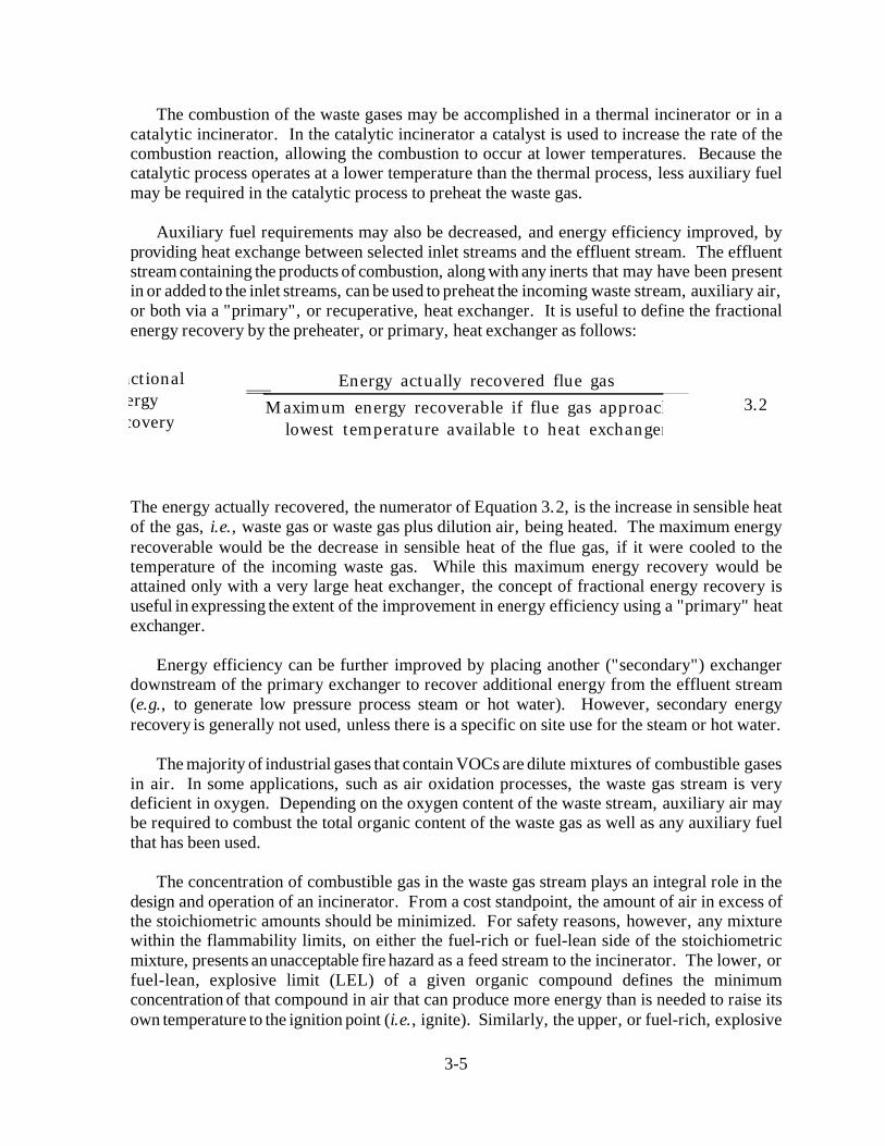
FractionalEnergyRecovery
Energy actually recovered flue gasMaximum energy recoverable if flue gas approaches
lowest temperature available to heat exchanger
3-5
3.2
The combustion of the waste gases may be accomplished in a thermal incinerator or in acatalytic incinerator. In the catalytic incinerator a catalyst is used to increase the rate of thecombustion reaction, allowing the combustion to occur at lower temperatures. Because thecatalytic process operates at a lower temperature than the thermal process, less auxiliary fuelmay be required in the catalytic process to preheat the waste gas.
Auxiliary fuel requirements may also be decreased, and energy efficiency improved, byproviding heat exchange between selected inlet streams and the effluent stream. The effluentstream containing the products of combustion, along with any inerts that may have been presentin or added to the inlet streams, can be used to preheat the incoming waste stream, auxiliary air,or both via a "primary", or recuperative, heat exchanger. It is useful to define the fractionalenergy recovery by the preheater, or primary, heat exchanger as follows:
The energy actually recovered, the numerator of Equation 3.2, is the increase in sensible heatof the gas, i.e., waste gas or waste gas plus dilution air, being heated. The maximum energyrecoverable would be the decrease in sensible heat of the flue gas, if it were cooled to thetemperature of the incoming waste gas. While this maximum energy recovery would beattained only with a very large heat exchanger, the concept of fractional energy recovery isuseful in expressing the extent of the improvement in energy efficiency using a "primary" heatexchanger.
Energy efficiency can be further improved by placing another ("secondary") exchangerdownstream of the primary exchanger to recover additional energy from the effluent stream(e.g., to generate low pressure process steam or hot water). However, secondary energyrecovery is generally not used, unless there is a specific on site use for the steam or hot water.
The majority of industrial gases that contain VOCs are dilute mixtures of combustible gasesin air. In some applications, such as air oxidation processes, the waste gas stream is verydeficient in oxygen. Depending on the oxygen content of the waste stream, auxiliary air maybe required to combust the total organic content of the waste gas as well as any auxiliary fuelthat has been used.
The concentration of combustible gas in the waste gas stream plays an integral role in thedesign and operation of an incinerator. From a cost standpoint, the amount of air in excess ofthe stoichiometric amounts should be minimized. For safety reasons, however, any mixturewithin the flammability limits, on either the fuel-rich or fuel-lean side of the stoichiometricmixture, presents an unacceptable fire hazard as a feed stream to the incinerator. The lower, orfuel-lean, explosive limit (LEL) of a given organic compound defines the minimumconcentration of that compound in air that can produce more energy than is needed to raise itsown temperature to the ignition point (i.e., ignite). Similarly, the upper, or fuel-rich, explosive

Control Eff., %Inlet mass rate VOC Outlet mass rate VOC
Inlet mass rate VOC×
3-6
3.3
limit (UEL) represents the highest concentration of the organic in air that is ignitable. In thelatter case, air is limiting the reaction. Both the LEL and the UEL are measured at ambientconditions. Empirically, it has been found that mixtures of hydrocarbons in air at their LELhave a heating value of approximately 50 Btu/scf.
Since the majority of industrial waste gases that contain VOCs are dilute mixtures ofcombustible gases in air, their heating value is low and their oxygen content exceeds thatrequired to combust both the waste organics (VOCs and others) and the auxiliary fuel. If awaste gas above 50 percent LEL (about 25 Btu/scf) is encountered, it must be diluted to satisfyfire insurance regulations. Generally, the streams are brought to below 25 percent LEL,although concentrations from 25 percent to 50 percent are permitted provided the waste streamis continuously monitored by LEL monitors. Because air is the usual diluent gas, care must betaken with preheating the diluted stream so that it remains below about 1200 F. (See discussionbelow on preheating.) A table showing LEL, UEL, and heats of combustion for selected organiccompounds is given in Appendix 3A.
The goal of any incineration system is to control the amount of VOCs released to theenvironment. Performance of a control device such as an incinerator can be described by acontrol efficiency, defined according to the following equation:
It is important to note, however, that incomplete combustion of the inlet VOCs could result inthe formation of other VOCs not originally present. For example, the incomplete oxidation ofdichloroethane can yield vinyl chloride. Both of these compounds are VOCs. The definitiongiven in Equation 3.3 would still be meaningful, however, as long as the newly formed VOC(e.g., vinyl chloride) is detected. This situation necessitates the complete chemical analysis ofthe inlet and outlet gas streams to confirm compliance with State and Federal regulations.

3-7
Figure 3.1: Thermal Incinerator - General Case
Performance of an incinerator can also be measured solely by the outlet VOC concentration,usually in ppmv.
There are a number of different incinerator designs. These designs can be broadly classifiedas thermal systems and catalytic systems. Thermal systems may be direct flame incineratorswith no energy recovery, flame incinerators with a recuperative heat exchanger, or regenerativesystems which operate in a cyclic mode to achieve high energy recovery. Catalytic systemsinclude fixed-bed (packed-bed or monolith) systems and fluid-bed systems, both of whichprovide for energy recovery. The following sections discuss design aspects of these systems.
3.2.1 Thermal Incinerators
The heart of the thermal incinerator is a nozzle-stabilized flame maintained by a combinationof auxiliary fuel, waste gas compounds and supplemental air added when necessary (see Figure3.1). Upon passing through the flame, the waste gas is heated from its inlet temperature (e.g.,100 F) to its ignition temperature. The ignition temperature varies for different compounds andis usually determined empirically. It is the temperature at which the combustion reaction rate(and consequently the energy production rate) exceeds the rate of heat losses, thereby raisingthe temperature of the gases to some higher value. Thus, any organic/air mixture will ignite ifits temperature is raised to a sufficiently high level.
The organic-containing mixture ignites at some temperature between the preheattemperature and the reaction temperature. That is, ignition, as defined in this section, occursat some point during the heating of a waste stream as it passes through the nozzle-stabilizedflame regardless of its concentration. The mixture continues to react as it flows through thecombustion chamber.

3-8
Compound Temperature, F
acrylonitrile 1,344allyl chloride 1,276benzene 1,350chlorobenzene 1,4071,2-dichloroethane 1,368methyl chloride 1,596toluene 1,341vinyl chloride 1,369
*Reference [1]
Table 3.1: Theoretical Reactor Temperatures Required for 99.99 Percent Destruction byThermal Incineration for a 1-Second Residence Time*
The required level of VOC control of the waste gas that must be achieved within the timethat it spends in the thermal combustion chamber dictates the reactor temperature. The shorterthe residence time, the higher the reactor temperature must be. The nominal residence time ofthe reacting waste gas in the combustion chamber is defined as the combustion chamber volumedivided by the volumetric flow rate of the gas. Most thermal units are designed to provide nomore than 1 second of residence time to the waste gas with typical temperatures of 1,200 to2,000 F. Once the unit is designed and built, the residence time is not easily changed, so thatthe required reaction temperature becomes a function of the particular gaseous species and thedesired level of control. Table 3.1 illustrates the variability in (theoretical) reactor temperaturesthat is required to destroy 99.99 percent of the inlet mass of various noxious compounds withexcess air for a 1-second reactor residence time [l].
These temperatures cannot be calculated a priori, although incinerator vendors can provideguidelines based on their extensive experience. In practice, most streams are mixtures ofcompounds, thereby further complicating the prediction of this temperature. Other studies[2,3,4], which are based on actual field test data, show that commercial incinerators shouldgenerally be run at 1600 F with a nominal residence time of 0.75 seconds to ensure 98%destruction of non-halogenated organics. In some States the reactor temperature and residencetime of the unit are specified rather than attempting to measure actual levels of VOC control.The selected temperature must be maintained for the full, selected residence time forcombustion to be complete.
These three studies also conclude that mixing is a critical factor in determining thedestruction efficiency. Even though it cannot be measured, mixing is a factor of equal or evengreater importance than other parameters, such as temperature. The most feasible and efficientway to improve the mixing in an incinerator is to adjust it after start-up. The 98% control leveldiscussed in the previous paragraph presumes such an adjustment.

3-9
Ultimately, once the unit is built, it is the responsibility of the user to operate and maintainthe incinerator to insure compliance with applicable regulations.
3.2.1.1 Direct Flame Incinerators
Many configurations of thermal incinerators exist with the same goal—to raise the VOC-containing stream to the desired reaction temperature and hold it there for the given reactiontime to achieve the required destruction efficiency. The simplest example of such a system isthe direct flame incinerator. With reference to Figure 3.1, the direct flame incinerator iscomprised only of the combustion chamber. The waste gas preheater and the secondary energyrecovery heat exchanger are energy recovery devices and are not included as part of the directflame incinerator.
3.2.1.2 Recuperative Incinerators
Recuperative incinerators have improved energy efficiency as a result of placing heatexchangers in the hot outlet gas streams. With reference to Figure 3.1, the recuperativeincinerator is comprised of the combustion chamber, the waste gas preheater, and, ifappropriate, the secondary, energy recovery heat exchanger.
Primary Energy Recovery (Preheating Inlet Streams) Considerable fuel savings can berealized by using the exit (product) gas to preheat the incoming feed stream, combustion air, orboth via a heat exchanger, as shown in Figure 3.1 in the so-called "recuperative" incinerator.These heat exchangers can recover up to 70% of the energy (enthalpy) in the product gas.
The two types of heat exchangers most commonly used are plate-to-plate and shell-and-tube. Plate-to-plate exchangers offer high efficiency energy recovery at lower cost than shell-and-tube designs. Also, because of their modular configuration, plate-to-plate units can be builtto achieve a variety of efficiencies. But when gas temperatures exceed 1000 F, shell-and-tubeexchangers usually have lower purchase costs than plate-to-plate designs. Moreover, shell-and-tube exchangers offer better long-term structural reliability than plate-to-plate units.[5] In anycase, because most incinerators installed are packaged units, the design (and cost) of therecuperative heat exchangers have already been incorporated.
Most heat exchangers are not designed to withstand high temperatures, so that most of theenergy needed to reach ignition is supplied by the combustion of fuel in the combustionchamber and only moderate preheat temperatures are sought in practice (<1200 F).
Secondary Energy Recovery (Additional Waste Energy Recovery) It should be noted,however, that at least some of the energy added by auxiliary fuel in the traditional thermal units(but not recovered in preheating the feed stream) can still be recovered. Additional heatexchangers can be added to provide process heat in the form of low pressure steam or hot waterfor on-site application. Obviously, an in-plant use for such low level energy is needed to realizethese savings.
The need for this higher level of energy recovery will be dependent upon the plant site. Theadditional heat exchanger is often provided by the incineration unit vendor. The cost of this
3-10
additional heat exchanger may be estimated via standard heat exchanger correlations and shouldbe added to the costs estimated using the cost correlations in this chapter.
3.2.1.3 Regenerative Incinerators
A distinction in thermal incinerators can now be made on the basis of this limitation in thepreheat temperature. The traditional approach to energy recovery in the units (shownschematically in Figure 3.1) still requires a significant amount of auxiliary fuel to be burned inthe combustion chamber when the waste gas heating values are too low to sustain the desiredreaction temperature at the moderate preheat temperature employed. Additional savings can,under these conditions, be realized in units with more complete transfer of exit-stream energy.This is the concept behind the so-called excess-enthalpy or regenerable burner systems. Thesesystems use direct contact heat exchangers constructed of a ceramic material that can toleratethe high temperatures needed to achieve ignition of the waste stream.
The operation of the regenerative system is illustrated in Figure 3.2. The inlet gas firstpasses through a hot ceramic bed thereby heating the stream (and cooling the bed) to its ignitiontemperature. If the desired temperature is not attainable, a small amount of auxiliary fuel isadded in the combustion chamber. The hot gases then react (releasing energy) in the combustionchamber and while passing through another ceramic bed. thereby heating it to the combustionchamber outlet temperature. The process flows are then switched, now feeding the inlet streamto the hot bed. This cyclic process affords very high energy recovery (up to 95%).
The higher capital costs associated with these high-performance heat exchangers andcombustion chambers may be offset by the increased auxiliary fuel savings to make such asystem economical. The costs of these regenerative units will be given separately in the costcorrelations presented in Section 3.5. Regenerative incinerators are not packaged units but arefield-erected only. Accordingly, the costs given in Section 3.5 for regenerative units are forfield-erected units.

3-11

3-12
Figure 3.2: Regenerable-type Thermal Incinerator
3-13
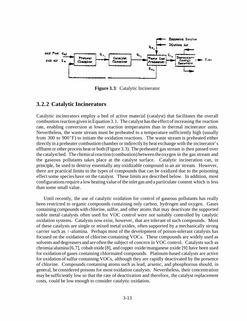
Figure 3.3: Catalytic Incinerator
3.2.2 Catalytic Incinerators
Catalytic incinerators employ a bed of active material (catalyst) that facilitates the overallcombustion reaction given in Equation 3.1. The catalyst has the effect of increasing the reactionrate, enabling conversion at lower reaction temperatures than in thermal incinerator units.Nevertheless, the waste stream must be preheated to a temperature sufficiently high (usuallyfrom 300 to 900 F) to initiate the oxidation reactions. The waste stream is preheated eitherdirectly in a preheater combustion chamber or indirectly by heat exchange with the incinerator'seffluent or other process heat or both (Figure 3.3). The preheated gas stream is then passed overthe catalyst bed. The chemical reaction (combustion) between the oxygen in the gas stream andthe gaseous pollutants takes place at the catalyst surface. Catalytic incineration can, inprinciple, be used to destroy essentially any oxidizable compound in an air stream. However,there are practical limits to the types of compounds that can be oxidized due to the poisoningeffect some species have on the catalyst. These limits are described below. In addition, mostconfigurations require a low heating value of the inlet gas and a particulate content which is lessthan some small value.
Until recently, the use of catalytic oxidation for control of gaseous pollutants has reallybeen restricted to organic compounds containing only carbon, hydrogen and oxygen. Gasescontaining compounds with chlorine, sulfur, and other atoms that may deactivate the supportednoble metal catalysts often used for VOC control were not suitably controlled by catalyticoxidation systems. Catalysts now exist, however, that are tolerant of such compounds. Mostof these catalysts are single or mixed metal oxides, often supported by a mechanically strongcarrier such as -alumina. Perhaps most of the development of poison-tolerant catalysts hasfocused on the oxidation of chlorine-containing VOCs. These compounds are widely used assolvents and degreasers and are often the subject of concern in VOC control. Catalysts such aschromia/alumina [6,7], cobalt oxide [8], and copper oxide/manganese oxide [9] have been usedfor oxidation of gases containing chlorinated compounds. Platinum-based catalysts are activefor oxidation of sulfur containing VOCs, although they are rapidly deactivated by the presenceof chlorine. Compounds containing atoms such as lead, arsenic, and phosphorous should, ingeneral, be considered poisons for most oxidation catalysts. Nevertheless, their concentrationmay be sufficiently low so that the rate of deactivation and therefore, the catalyst replacementcosts, could be low enough to consider catalytic oxidation.
3-14
Compound Temperature, FCO O3 4 Pt - Honeycomb
acrolein 382 294n-butanol 413 440n-propylamine 460 489toluene 476 373n-butyric acid 517 4511,1,1-trichloroethane 661 >>661dimethyl sulfide — 512
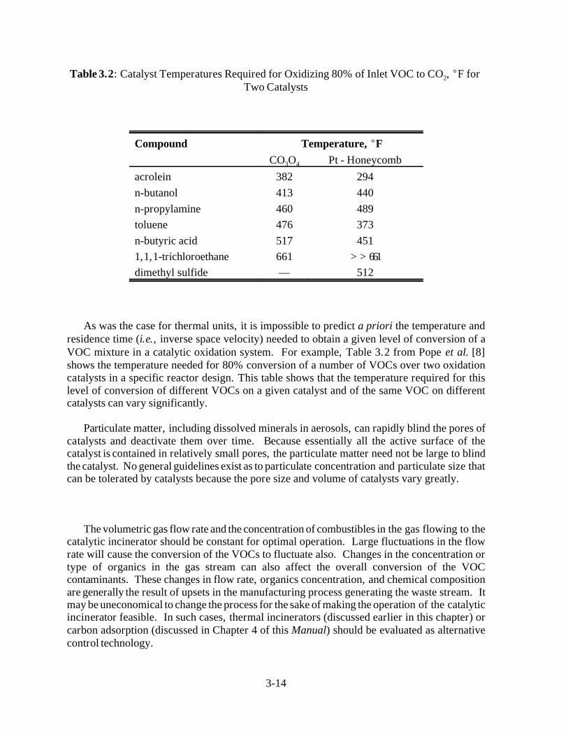
Table 3.2: Catalyst Temperatures Required for Oxidizing 80% of Inlet VOC to CO , F for 2
Two Catalysts
As was the case for thermal units, it is impossible to predict a priori the temperature andresidence time (i.e., inverse space velocity) needed to obtain a given level of conversion of aVOC mixture in a catalytic oxidation system. For example, Table 3.2 from Pope et al. [8]shows the temperature needed for 80% conversion of a number of VOCs over two oxidationcatalysts in a specific reactor design. This table shows that the temperature required for thislevel of conversion of different VOCs on a given catalyst and of the same VOC on differentcatalysts can vary significantly.
Particulate matter, including dissolved minerals in aerosols, can rapidly blind the pores ofcatalysts and deactivate them over time. Because essentially all the active surface of thecatalyst is contained in relatively small pores, the particulate matter need not be large to blindthe catalyst. No general guidelines exist as to particulate concentration and particulate size thatcan be tolerated by catalysts because the pore size and volume of catalysts vary greatly.
The volumetric gas flow rate and the concentration of combustibles in the gas flowing to thecatalytic incinerator should be constant for optimal operation. Large fluctuations in the flowrate will cause the conversion of the VOCs to fluctuate also. Changes in the concentration ortype of organics in the gas stream can also affect the overall conversion of the VOCcontaminants. These changes in flow rate, organics concentration, and chemical compositionare generally the result of upsets in the manufacturing process generating the waste stream. Itmay be uneconomical to change the process for the sake of making the operation of the catalyticincinerator feasible. In such cases, thermal incinerators (discussed earlier in this chapter) orcarbon adsorption (discussed in Chapter 4 of this Manual) should be evaluated as alternativecontrol technology.
3-15
The method of contacting the VOC-containing stream with the catalyst serves to distinguishcatalytic incineration systems. Both fixed-bed and fluid-bed systems are used.
3.2.2.1 Fixed-Bed Catalytic Incinerators
Fixed-bed catalytic incinerators may use a monolith catalyst or a packed-bed catalyst. Each ofthese is discussed below.
Monolith Catalyst Incinerators The most widespread method of contacting the VOC-containing stream with the catalyst is the catalyst monolith. In this scheme the catalyst is aporous solid block containing parallel, non-intersecting channels aligned in the direction of thegas flow. Monoliths offer the advantages of minimal attrition due to thermal expansion/contraction during startup/shutdown and low overall pressure drop.
Packed-Bed Catalytic Incinerators A second contacting scheme is a simple packed-bed inwhich catalyst particles are supported either in a tube or in shallow trays through which thegases pass. The first scheme is not in widespread use due to its inherently high pressure drop,compared to a monolith, and the breaking of catalyst particles due to thermal expansion whenthe confined catalyst bed is heated/cooled during startup/shutdown. However, the tray typearrangement, where the catalyst is pelletized is used by several industries (e.g., heat-set web-offset printing). Pelletized catalyst is advantageous where large amounts of such contaminantsas phosphorous or silicon compounds are present.[10]
3.2.2.2 Fluid-Bed Catalytic Incinerators
A third contacting pattern between the gas and catalyst is a fluid-bed. Fluid-beds have theadvantage of very high mass transfer rates, although the overall pressure drop is somewhathigher than for a monolith. An additional advantage of fluid-beds is a high bed-side heattransfer as compared to a normal gas heat transfer coefficient. This higher heat transfer rate toheat transfer tubes immersed in the bed allows higher heat release rates per unit volume of gasprocessed and therefore may allow waste gas with higher heating values to be processed withoutexceeding maximum permissible temperatures in the catalyst bed. In these reactors the gasphase temperature rise from gas inlet to gas outlet is low, depending on the extent of heattransfer through imbedded heat transfer surfaces. The catalyst temperatures depend on the rateof reaction occurring at the catalyst surface and the rate of heat exchange between the catalystand imbedded heat transfer surfaces.
As a general rule, fluid-bed systems are more tolerant of particulates in the gas stream thaneither fixed-bed or monolithic catalysts. This is due to the constant abrasion of the fluidizedcatalyst pellets, which helps remove these particulates from the exterior of the catalysts in acontinuous manner.
A disadvantage of a fluid-bed is the gradual loss of catalyst by attrition. Attrition-resistantcatalysts have been developed to overcome this disadvantage.[11]

3-16
3.2.3 Other Considerations: Packaged versus Field-Erected Units,Auxiliary Equipment
3.2.3.1 Packaged vs. Field-Erected Units
With the exception of regenerative incinerators, the equipment cost correlations included in thischapter are for packaged units only. They are not valid for field-erected units. For regenerativeincinerators, the correlations are valid for field-erected units only. Packaged units are units thathave been shop fabricated and contain all elements necessary for operation, except forconnection to facilities at the site, e.g., utilities. The elements include the combustion chamber,preheater, instrumentation, fan, and the necessary structural steel, piping, and electricalequipment. This equipment is assembled and mounted on a "skid" to facilitate installation ona foundation at the plant site. Tie-in to the local emission source is not part of the packagedunit. Units are usually sized to handle flow rates of <20,000 scfm, but can be built toaccommodate flow rates up to 50,000 scfm. The cost correlations in this chapter are valid to50,000 scfm for packaged units, except for fluid-bed units which are valid to 25,000 scfm.
Conversely, field-erected units may be built to any desired size. The combustion chamber,preheater, and other equipment items are designed and fabricated individually, and assembledat the site. However, both the equipment and installation costs of field-erected units aretypically higher than those for equivalent-sized packaged units because the factors that improveefficiency of shop-fabrication, such as uniform working environment, availability of tools andequipment, and more efficient work scheduling, are generally not available in the field.
3.2.3.2 Acid Gas Scrubbers
The final outlet stream of any incineration system may contain certain pollutants that must beremoved. The combustion of sulfur-containing compounds results in SO , while chlorinated2compounds yield Cl and HCl in the product stream. These acid gases must be removed from2the gas stream if they are present at significant concentrations (regulations for limits on thesegases vary from state to state). This removal can be effected in, for instance, a packed-bed gasabsorber (vertical scrubber) in which the flue gas is contacted with a caustic scrubbing liquid.For fluid-bed catalytic reactors, venturi scrubbers are often used because they provide forparticulate removal as well as acid gas scrubbing. In most cases adding a scrubber or absorbersignificantly increases the cost of the incineration unit, sometimes by a factor of two. Costingof absorbers is discussed in the "Gas Absorbers" chapter (Chapter 9) of this Manual.
If chlorinated VOCs are present in the waste gas, heat exchangers may require specialmaterials of construction. This added expense is not included in the costing procedures outlinedin this chapter.
3.2.3.3 Heat Exchangers (Preheaters and Other Waste Energy Recovery Units)
For the thermal and catalytic units having some degree of energy recovery, the cost of theprimary heat exchanger is included in the cost, and its design is usually done by the incinerationunit vendor. The cost correlations presented in this chapter include units both with and without
3-17
energy recovery. Secondary energy recovery, if desired, requires an additional heat exchanger,which is also often provided by the incineration unit vendor. Costing procedures for secondaryenergy recovery are not included in this chapter.
3.2.3.4 Other Auxiliary Equipment
Additional auxiliary equipment such as hoods, ductwork, precoolers, cyclones, fans, motors, andstacks are addressed separately in other chapters of this Manual.
3.2.4 Technology Comparison
Both the thermal and catalytic incineration systems are designed to provide VOC controlthrough combustion at a level in compliance with applicable state and federal requirements.Given the wide range of options available, however, it is obvious that not every incinerator willfulfill these requirements at the same cost. This section presents a first step toward decidinghow best to deal with VOC emission abatement using incinerators considering some qualitativefactors pertinent to the types of incinerators described in this chapter. It is the intent of theremainder of Chapter 3 to provide a method by which the cost of VOC control for a particularapplication can be calculated.

3-18
4444444444444444444444444444444444444444444444444444444444444444444444
Thermal Systems
Direct Flame Incinerator
Recuperative Incinerator (Direct Flame with Recuperative HeatExchanger)
Regenerative Incinerator Operating in a Cyclic Mode
Catalytic Systems
Fixed-Bed
– Monolith
– Packed-Bed
Fluid-Bed
4444444444444444444444444444444444444444444444444444444444444444444444
Table 3.3: Principal VOC Incinerator Technologies
A summary of the principal types of incinerators is presented in Table 3.3. From the earlierdiscussions, the following factors relating to the presence of contaminants should be consideredby potential users [12]:
The fouling of the catalyst in a catalytic system is a possibility. Poisons to the systeminclude heavy metals, phosphorous, sulfur and most halogens, although catalysts havebeen developed that are chlorine resistant.
The possibility of process upsets that could release any of the above poisons or causefluctuations in the heating value to the incinerator would favor a thermal system.
Except for the No.2 grade, fuel oil should not be considered as auxiliary fuel to acatalytic system due to the sulfur and vanadium it may contain.[10]
All of the above factors would serve to increase the operating expense of a catalytic unit throughreplacement costs of the catalyst. An additional factor relates to relative energy efficiency ofthe various types of incinerators:

3-19
Thermal units generally require more auxiliary fuel than catalytic units and operate attemperatures that are roughly 1000 F higher. This difference in fuel requirementincreases as the heating value of the waste stream decreases.
In general, a trade-off exists between the higher capital costs of catalytic incinerators andthe higher operating costs of thermal incinerators. This difference will be illustrated by a designexample presented in Section 3.4 which treats both technologies.
3.3 General Treatment of Material and Energy Balances
In the sizing and costing of the incinerator and the calculation of the auxiliary fuel requirements,it is necessary to make material and energy balances around the entire incinerator unit andaround certain parts of the unit, such as the combustion chamber or the preheater. This sectionpresents a general approach to making these balances.
These balances are based on the law of conservation of mass and energy. They can be statedin general equation form as
In - Out + Generation = Accumulation (3.4)
Because the incineration process is a steady-state process, the accumulation term is zero and theequation becomes
In - Out + Generation = 0
For mass balances it is useful to restrict the balances to be made on the mass of each atomicspecies so that for mass balances the generation term becomes zero. However, because thecombustion reaction liberates energy, the energy balances around equipment where combustiontakes place would include a generation term. Thus, the simplified equations are
In - Out = 0 , for steady-state mass balances (3.5)
In - Out + Generation = 0 , for steady-state energy balances (3.6)
For the incineration process the two terms In and Out are generally mass terms (for a massbalance) of the form,
Q
where= density (mass per unit volume)
Q = volumetric flow rate (volume per unit time)

3-20
or sensible heat terms (for an energy balance) of the form,
QC (T - T )p ref
whereC = heat capacity pT = temperature
The reference temperature, T , is often taken to be zero or the temperature of arefconvenient stream, e.g., the inlet gas stream, in whatever units T is in, so the T term may notref
appear in the equations. When the reference temperature is taken as zero, the sensible heatterms become
QC T.p
Energy losses, H , are also part of the Out term and, for the incinerator process, are taken hereL
to be 10% of the total energy input to the incinerator.
For the incineration process, the generation term for energy balances accounts for theenergy released through the combustion reactions. This term is generally of the form
Q(- h )c
where (- h ) = heat of combustion.c
3.4 Design Procedures
The following procedure is designed to provide parameters for use in developing a study costestimate (accuracy ± 30%). The principal parameters of interest are
flue gas flow rate, upon which all the equipment cost correlations are based.
auxiliary fuel requirement, which is important in estimating annual operating costs.
For applications which involve control of waste gas streams that are dilute mixtures of VOCsin air (>20% oxygen in the waste gas stream), the flue gas flow rate is greater than the inletwaste gas flow rate by the amount of auxiliary fuel and the increase in the moles of gas as aresult of the combustion reaction. Because these two factors usually cause only small increasesin flow rate, a number of simplifying assumptions can be made in the design calculations. For
3-21
applications where diluent air must be used to adjust the combustible concentration in the wastegas to 25% LEL and where auxiliary fuel and auxiliary combustion air are needed, morecomplete mass and energy balances must be made.
The design procedure illustrated below is for waste gas streams that are dilute mixtures ofVOCs in air (>20% oxygen in the waste gas stream). In this discussion the design procedurewill be illustrated by a sample problem that will be solved step-by-step.
3.4.1 Steps Common to Thermal and Catalytic Units
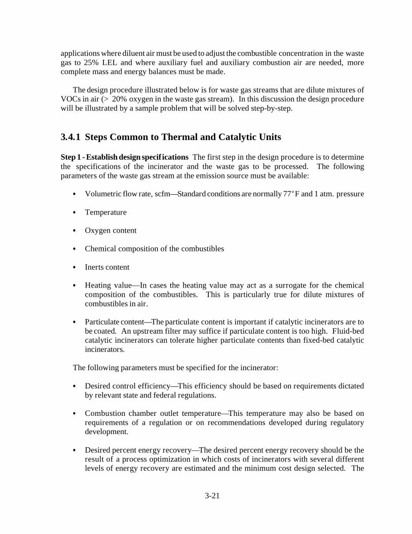
Step 1 - Establish design specifications The first step in the design procedure is to determinethe specifications of the incinerator and the waste gas to be processed. The followingparameters of the waste gas stream at the emission source must be available:
Volumetric flow rate, scfm—Standard conditions are normally 77 F and 1 atm. pressure
Temperature
Oxygen content
Chemical composition of the combustibles
Inerts content
Heating value—In cases the heating value may act as a surrogate for the chemicalcomposition of the combustibles. This is particularly true for dilute mixtures ofcombustibles in air.
Particulate content—The particulate content is important if catalytic incinerators are tobe coated. An upstream filter may suffice if particulate content is too high. Fluid-bedcatalytic incinerators can tolerate higher particulate contents than fixed-bed catalyticincinerators.
The following parameters must be specified for the incinerator:
Desired control efficiency—This efficiency should be based on requirements dictatedby relevant state and federal regulations.
Combustion chamber outlet temperature—This temperature may also be based onrequirements of a regulation or on recommendations developed during regulatorydevelopment.
Desired percent energy recovery—The desired percent energy recovery should be theresult of a process optimization in which costs of incinerators with several differentlevels of energy recovery are estimated and the minimum cost design selected. The
Content, Vol. % 100.01000
106× 100
1000
106× 100
99.8%
Oxygen Content, % Air Content × 0.20920.86%
3-22
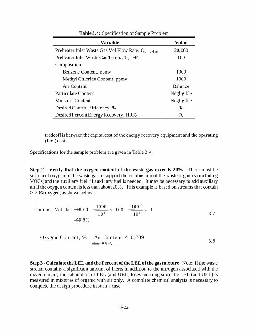
Variable ValuePreheater Inlet Waste Gas Vol Flow Rate, Qwi scfm 20,000Preheater Inlet Waste Gas Temp., T Fwi, 100Composition
Benzene Content, ppmv 1000Methyl Chloride Content, ppmv 1000Air Content Balance
Particulate Content NegligibleMoisture Content NegligibleDesired Control Efficiency, % 98Desired Percent Energy Recovery, HR% 70
Table 3.4: Specification of Sample Problem
3.7
3.8
tradeoff is between the capital cost of the energy recovery equipment and the operating(fuel) cost.
Specifications for the sample problem are given in Table 3.4.
Step 2 - Verify that the oxygen content of the waste gas exceeds 20% There must besufficient oxygen in the waste gas to support the combustion of the waste organics (includingVOCs) and the auxiliary fuel, if auxiliary fuel is needed. It may be necessary to add auxiliaryair if the oxygen content is less than about 20%. This example is based on streams that contain>20% oxygen, as shown below:
Step 3 - Calculate the LEL and the Percent of the LEL of the gas mixture Note: If the wastestream contains a significant amount of inerts in addition to the nitrogen associated with theoxygen in air, the calculation of LEL (and UEL) loses meaning since the LEL (and UEL) ismeasured in mixtures of organic with air only. A complete chemical analysis is necessary tocomplete the design procedure in such a case.

LELmix
n
j 1
xj
(n
i 1xi) × LELj
1
n
i 1xi (1,000 1,000) × 10 6
2,000 × 10 6
LELmix1000
2,000 × 14,0001000
2,000 × 82,500
1
23,938 ppmv
LELmix
total combustible conc. in mixtureLELmix
× 100
2,00023,938
× 100 8.4%
3-23
3.9
3.10
3.11
3.12
3.13
The example chosen here is typical, in that there is more than one VOC component in thegas stream. An approximate method to calculate the LEL of a mixture of compounds, LEL ,mixis given by Grelecki [13] as
wherex = volume fraction of combustible component ii
LEL = lower explosive limits of combustible component j (ppmv)j
n = number of combustible components in mixture
For the example case,
From standard references [14] or from Appendix 3A,
LEL = 14,000ppnv fir benzeneBzLEL = 82,5000 ppmv for methyl chlorideMC

( hcw)
n
i 1( hc i
) xi
( hcw) heat of combustion of the waste stream (Btu/scf)
( hc i) volumetric heat of combustion of component i at 25 C (Btu/scf)
xi volume fraction of component i in the waste gasn number of combustible components in the waste gas
( hcBz) 3,475 Btu/scf for benzene
( hcMC) 705 Btu/scf for methyl chloride
xBz 1,000 ppmv × 10 6 10 3 for benzene
xMC 1,000 ppmv × 10 6 10 3 for methyl chloride
3-24
3.14
The percent LEL of the mixture is therefore 8.4%. Because this is well below 25%, nodilution air is needed in this example. If the mixture had been above 25% LEL, sufficientdilution air would have been needed to bring the concentration of the mixture to less than 25%to satisfy fire insurance regulations.
Step 4 - Calculate the volumetric heat of combustion of the waste gas streams, ( - hcw),Btu/scf The energy content of the gas stream, expressed in terms of the heat of combustion, iscalculated as follows:
where
The heat of combustion that should be used in these calculations is the "lower" heat ofcombustion, i.e., with gaseous water, rather than liquid water, as a reaction product since waterleaves the incinerator in the vapor state. From Appendix 3A or standard references [14,15] withappropriate conversion of units, the volumetric heat of combustion at 25 C for the twocomponents is calculated to be as follows:
The compositions specified earlier as ppmv are converted to volume fractions as follows:
Using these values of heat of combustion and composition, the heat of combustion of thewaste gas stream per standard cubic foot of incoming gas is
( hcw) (3,475) (10 3) (705) (10 3)
4.18 Btu/scf
( hcw) 56.6 Btu/lb
3-25
3.15
Assuming the waste gas is principally air, with a molecular weight of 28.97 and acorresponding density of 0.0739 lb/scf, the heat of combustion per pound of incoming waste gasis
The negative heat of combustion, by convention, denotes an exothermic reaction. Also byconvention, if one refers to heat of reaction rather than heat of combustion, then a positive valuedenotes an exothermic reaction.
Empirically, it has been found that 50 Btu/scf roughly corresponds to the LEL of organic/airmixtures. Insurance codes require a value below 25% LEL, which corresponds to about 13Btu/scf. However, if LEL sensors and monitors are installed, one can incinerate a waste gaswith a combustible organic content between 25 and 50% LEL, which corresponds to 13 to 25Btu/scf.
For catalytic applications the heat of combustion must normally be less than 10 Btu/scf (forVOCs in air) to avoid excessively high temperatures in the catalyst bed. This is, of course, onlyan approximate guideline and may vary from system to system.
After Step 4, determination of the (- hcw) design procedure for thermal and catalyticincinerators is discussed separately, beginning with Step 5 for each type of incinerator.
3.4.2 Steps Specific to Thermal Units
Figure 3.1 shows a generic thermal incinerator with the appropriate streams labeled.
Step 5t - Establish the temperature at which the incinerator will operate As mentioned inSection 3.2.1, both the reactor temperature and residence time of the waste gas in the reactordetermine the level of VOC destruction. In general, state and local regulations specify therequired level of destruction that the customer must meet. In this example a destructionefficiency of 98 percent is specified. Studies by Mascone [2,3,4] show that this destructionefficiency can be met in a thermal incinerator operated at a temperature, T , of 1,600 F and afi
residence time of 0.75 second. (Note: This higher efficiency level is the minimum achievableby any new properly designed and operated incinerator. Many incinerators can achievedestruction efficiencies of 99% or higher.)

Fractional Energy RecoveryTwo
Twi
Tfi Twi
3-26
3.16
Step 6t - Calculate the waste gas temperature at the exit of the preheater The extent of theheat exchange to be carried out in the preheater is the result of a technical and economicoptimization procedure that is not illustrated in this example. As the VOC stream temperatureleaving the heat exchanger, Two, increases, the auxiliary fuel requirement decreases, but at theexpense of a larger heat exchanger. However, there are several important limits on Two. First,Two must not be close to the ignition temperature of the organic-containing gas to preventdamaging temperature excursions inside the heat exchanger should the gas ignite. Second, forgases containing halogens, sulfur, and phosphorous (or other acid-forming atoms), the flue gastemperature after the heat exchanger, Tfo, must not drop below the acid dew point. Bothlimitations limit the amount of heat exchange and thus the maximum value of Two. Thecalculation of the acid dew point is not simple. It is recommended that vendor guidance besought to ensure that the dew point is not reached. Condensation of acid gases will result incorrosion of many of the metals used in heat exchangers. As an example, fuel sulfur contentsof 1 to 2 percent can give acid dew points of about 200 to 270 F. Increasing the sulfur contentto 4 percent can raise the dew to about 290 F. Chlorine and phosphorous have a much smallereffect on acid dew elevation.
With the following assumptions, one can estimate Two using equation 3.2, the definition offractional energy, recovery for a heat exchanger.
The fractional energy recovery is specified.
The amount of auxiliary fuel, Q , and auxiliary combustion air, Q , are small relativeaf ato the waste gas, Q , so that the mass flow rates of gases, Q and Q , on both sidesw w w f fof the preheater are approximately the same, or
Q Qw w f f
The heat capacities of the gases on both sides of the preheater are approximately thesame, regardless of composition. This is true for waste streams which are dilutemixtures of organics in air, the properties of the streams changing only slightly oncombustion.
The mean heat capacities above the reference temperature of the gases on both sides ofthe preheater are approximately the same regardless of temperature.
With these assumptions, the equation for fractional energy recovery for a heat exchangerbecomes

Two1,150 F
TfiTfo
TwoTwi
Tfo550 F
3-27
For this example with a fractional energy recovery of 0.70, an incinerator operating temperature,Tf wi, of 1600 F, and a waste gas inlet temperature, T i, of 100 F, the waste gas temperature atthe end of the preheater becomes
The temperature of the exhaust gas, Tfo, can be determined by an energy balance on thepreheater, which, with the same assumptions as used in deriving Equation 3.16 regarding themass flow rates and average heat capacities of the gases involved, results in the followingequation:
i.e., the temperature rise in the waste gas is approximately equal to the temperature decrease inthe flue gas with which it is exchanged. For this example, this results in
This value of Tfo should be well above the acid dew point of the flue gas stream.
It should be remembered that Two should be well below the ignition temperature of the VOCstream to prevent unwanted temperature excursions in the preheater. This must be verified evenif the stream is well below the LEL because flammability limits can be expanded by raising thereactant stream temperature. A sufficiently high preheat temperature, Two, could initiatereaction (with heat release) in the preheater. This would ordinarily be detrimental to thematerials of construction in the heat exchanger. The one exception is the thermal incineratorof the regenerable type described in Section 3.2. The 95-percent energy recovery, obtainablein regenerable systems would result in this example in a Two of 1,525 F. The significantreaction rate that would occur at this temperature in the ceramic packing of the heatexchanger/reactor is by design.
Step 7t - Calculate the auxiliary fuel requirement, Q Auxiliary fuel will almost invariablyafbe needed for startup of the unit. However, at steady state, if the energy released by combustionof the organics present in the waste stream is sufficient to maintain the reactor temperature(1,600 F in the example), only a small amount of auxiliary fuel (< 5% of the total energy input)is needed to stabilize the flame. In most cases, however, more fuel than just this stabilizing fuelwill be required to maintain the reactor temperature.

HL 0.1 fiQfiCpmfi(Tfi Tref)
afQaf
wiQwi
[Cpmair(1.1Tfi
Two0.1Tref) ( hcwo
)]
( hcaf) 1.1Cpmair
(Tfi Tref)
wo wi0.0739 lb /scf, air at 77 F, 1 atm.
3-28
3.17
3.18
With the following assumptions, one can estimate Q using a mass and energy balanceaf
around the combustion chamber and following the principles discussed in Section 3.3, withreference to Figure 3.1.
The reference temperature, T , is taken as the inlet temperature of the auxiliary fuel, T .ref af
No auxiliary air, Q , is required.a
Energy losses, H , are assumed to be 10% of the total energy input to the incineratorL
above ambient conditions.[16,17] Thus, if the reference temperature is near ambientconditions,
The heat capacities of the waste gases entering and leaving the combustion chamber areapproximately the same, regardless of composition. This is true for waste streams whichare dilute mixtures of organics in air, the properties of the streams changing only slightlyon combustion.
The mean heat capacities above the reference temperature of the waste gases enteringand leaving the combustion chamber are approximately the same regardless oftemperature. Thus the mean heat capacity for the waste gas stream entering or leavingthe combustion chamber should be evaluated at the average of Tw fo and T i. For air thisassumption introduces an error of, at most, 5% over the temperatures of interest.
With these assumptions, the mass and energy balance around the combustion chamberreduces to the following equation:
Input data for this equation are summarized below:
The waste stream is essentially air so that

QwoQwi
20,000 scfm
( hcaf) 21,502 Btu/lb, for methane
Taf Tref 77 F, assume ambient conditions
af 0.0408 lb/ft 3, methane at 77 F ,1 atm.Tfi 1,600 F, Step 5t
Two1,150 F, Step 6t
( hcwo
) 56.6 Btu/lb. Step4
3-29
T = 77 Fref
Stream Subscript, j,j
lb/scfQ ,j
scfmC ,pmj
Btu/lb FT ,jF
IN - Sensible heat
Auxiliary Air a na* na* na* na*
Auxiliary Fuel af 0.0408 167 ** 77
Waste Gas wo 0.0739 20,000 0.255 1,150
OUT - Sensible Heat
Waste Stream fi 0.0739 20,167 0.255 1,600
(- h ), waste gas = 56.6 Btu/lbc
(- h ), auxiliary fuel = 21,502 Btu/lbc
*Not applicable.**Not used because reference temperature is taken equal to auxiliary fuel temperature.
Table 3.5: Summary of Example Problem Variable Valuation
Cpmair = 0.255Btu/lb F, the mean heat capacity of air between 77 F and 1,375 F (theaverage temperature of the waste gas entering and leaving thecombustion chamber)
Other input data to Equation 3.18 include:
substituting the above values into Equation 3.18 results in:
Q = 167 scfmaf

3-30
Stream Subscript, jValue,
Btu/min
IN - Sensible Heat, Q C (T - T )j j pmj i ref
Auxiliary AirWaste Gas
awo
0404,403
OUT - Sensible Heat, Q C (T - T )j j pmj i ref
Waste Stream fi 578,796
OUT - Losses10% of total energy input 57,880
GENERATION - Heat of Combustion, Q (- h )j j ej
Waste GasAuxiliary Fuel
wo
af83,655146,506
Table 3.6: Terms in Energy Balance Around Combustor—Example Problem
The values of the parameters in the energy balance are summarized in Table 3.5.
It is instructive to examine the magnitude of the various terms in the energy balance aroundthe combustor for the sample problem. This is done in Table 3.6. The energy balance showndoes not quite add to zero due to round-off-error and simplifying assumptions. Table 3.6 showsthat the largest inlet term is the sensible heat of the incoming waste gas. The heat of combustionof the organics contained in the waste gas stream is somewhat smaller than that of the auxiliarymethane because of the relatively small amount of organics in the waste gas stream. The largestterm in the outlet stream is the sensible heat of the outgoing waste stream. The overall energylosses are based on an assumption, but are relatively small. Because the sensible heat contentsof the entering and leaving waste stream are so large, it is apparent that energy recovery is animportant factor in achieving energy efficiency. In fact, with zero energy recovery in thesample problem, the auxiliary fuel requirements would be 605 scfm, about four times the energyrequirements based on 70% energy recovery.
Step 8t - Verify that the auxiliary fuel requirement is sufficient to stabilize the burnerflame Only a small amount of auxiliary fuel (< 5% of the total energy input) is needed tostabilize the burner flame. In general, more fuel than just this stabilizing fuel will be requiredto maintain the reactor temperature. It is wise to verify that the auxiliary fuel requirementcalculated in Step 7t is sufficient for stabilization. If it is insufficient, then a minimum amountof auxiliary fuel must be used, and the amount of energy recovery, specified earlier must bereduced to avoid exceeding the specified temperature at which the incinerator will operate (Step5t).
This check is made by calculating 5% of the total energy input to the incinerator andcomparing it with the auxiliary fuel energy input. The total energy input is given as follows:

Total Energy Input fiQfiCpmfi(Tfi Tref)
Auxiliary Fuel Energy Input af Qaf ( hcaf)
Qfi QwoQa Qaf
20,000 0 16720,167 scfm
3-31
3.19
3.20
The auxiliary fuel used in the design, Q , should be the larger of 5% of the total energy inputaf(28,900 Btu/min.) and the auxiliary fuel energy input (146,500 Btu/min.). The auxiliary fuelused easily meets this criterion.
Step 9t - Calculate the total volumetric flow rate of gas through the incinerator, Q Thefitotal volumetric flow rate of gas leaving the incinerator is referred to as the flue gas flow rate,Q , and is the gas rate on which the incinerator sizing and cost correlations are based. The fluefigas flow rate measured at the standard conditions of 77 F and 1 atmosphere, where the increasein volumetric throughput due to an increase in the number of moles of gas as a result ofcombustion is neglected, is the sum of the inlet streams to the incinerator.
This result conforms with the assumptions stated in Step 6t, i.e., the mass (and volume) flowrates on both sides of the preheater are approximately equal. Finally, it must be emphasized thatsteps 5t to 9t apply to thermal recuperative incinerators, only. To calculate the auxiliary fuelrequirements for other types of thermal incinerators (e.g., regenerative), a different proceduremust be used. (See Appendix 3B.)
3.4.3 Steps Specific to Catalytic Units
Figure 3.3 shows a generic catalytic incinerator with the appropriate streams labeled. Theapproach used in the calculations on the catalytic incinerator is somewhat different than thatused in the thermal incinerator. This difference arises because of additional constraints whichare placed on the catalytic incinerator. These constraints are as follows:
The desired catalyst bed outlet temperature is typically 700 to 900 F. The maximumtemperature to which the catalyst bed can be exposed continuously is limited to about1,200 F. Therefore, the combustible content of the waste gas is limited, and the amountof heat exchange that occurs in the primary heat exchanger may be limited.
The inlet temperature to the catalyst bed itself must be above the catalytic ignitiontemperature required to give the desired destruction efficiency in the incinerator.Therefore, the combustible content of the waste gas is further limited to that which,

Two660 F
3-32
when combusted, will raise the temperature in the catalyst bed no more than the Tbetween the required reactor bed inlet temperature, and the desired reactor bed outlettemperature.
Auxiliary fuel, in combination with the preheat from the primary heat exchanger, is usedto preheat the waste gas to the reactor inlet temperature. A minimum amount ofauxiliary fuel (< 5% of the total energy input) must be used to stabilize the flame in thepreheat combustion chamber. This has the effect of further limiting the combustiblecontent of the waste gas stream and the amount of heat exchange permissible in theprimary heat exchanger.
The steps outlined below represent one approach to recognizing these constraints andincorporating them into the calculation procedures.
Step 5c - Establish the desired outlet temperature of the catalyst bed, T The energyfi
released by the oxidation of the VOCs in the catalyst bed will raise the temperature of the gasesby an amount, T, as the gases pass through the catalyst bed. An outlet temperature from thecatalyst, and thus from the reactor, must be specified that will ensure the desired level ofdestruction of the VOC stream. As in thermal incinerators, this value varies from compoundto compound and also varies from catalyst to catalyst. Final design of the incinerator should bedone by firms with experience in incinerator design. Guidelines given by CombustionEngineering [12] indicate that values from 300 to 900 F result in destruction efficienciesbetween 90 and 95 percent. To prevent deactivation of the catalyst a maximum bed temperatureof 1,200 F should not be exceeded. In the example problem the catalyst outlet temperature, T ,fiis selected to be 900 F.
Step 6c - Calculate the waste gas temperature at the exit of the preheater (primary) heatexchanger The waste gas temperature at the exit of the primary heat exchanger is estimatedin the same manner as for the thermal incinerator. The equation for fractional energy recoveryEquation 3.16, is used, with the same assumptions as used for the thermal incinerator. For theexample problem with a fractional energy recovery of 0.70, a catalyst bed outlet temperature,T , of 900 F, and a waste gas inlet temperature, Tfi wi, of 100 F, the gas temperature at the exitof the preheater becomes
The same considerations regarding the closeness of the temperature of the exhaust gas, T ,fa
to its dew point apply to the catalytic incinerator as they did to the thermal incinerator.
Step 7c - Calculate the auxiliary fuel requirement, Q The auxiliary fuel requirement, Q ,af af
is calculated by making mass and energy balances around the preheater combustion chamberand the catalyst chamber. The auxiliary fuel requirement calculated in this manner must bechecked to insure that it falls within the constraints imposed by design considerations of thecatalytic incinerator. These constraints are as follows:

QwoQw i
20,000 scfm
( hcaf) 21,502 Btu/lb, for methane
Taf 77 F, assumeambientconditions
af 0.0408 lb/ft 3, methane at 77 F, 1atm.Tfi 900 F, from Step 5c
Two660 F, from Step 6c
( hcw) 56.6 Btu/lb, from Step 4
3-33
The auxiliary fuel requirement must be positive. A negative fuel requirement indicatesthat the heat of combustion of the waste gas, (- h ), is too high for the fractional energyc
recovery in the primary heat exchanger that was selected.
The auxiliary fuel amount must be high enough to provide a stable flame in thepreheater combustion chamber (See Step 8c below).
An energy balance around the preheater combustion chamber and the catalyst chamber,taken together, results in Equation 3.18, the same equation used in the thermal incineratorcalculations. The input data for Equation 3.18 for the catalytic incinerator example problem aresummarized below:
The waste stream is essentially air so that
w wo = i = 0.0739 lb/scf, air at 77 F, 1 atmCpmair = 0.248 Btu/lb F, the mean heat capacity of air between 77 F and 780 F (the
average of the preheater exit and catalyst bed outlettemperatures)
Other input data to Equation 3.18 include
Substituting the above values into Equation 3.18 results in
Q = 40 scfmaf
If the outlet temperature of the catalyst bed, T , is 800 F, then Q , decreases to -6.7 scfm.fi af
In other words, no auxiliary fuel would, theoretically, be required at this bed temperature.However, as discussed above in Step 8t, a certain quantity of auxiliary fuel would be requiredto maintain burner stability.
At 70% energy recovery and 900 F outlet catalyst bed temperature, a waste gas with a heatof combustion, (- hc afwo), of about 79.9 Btu/lb would cause the auxiliary fuel requirement, Q , tobecome negative, indicating the catalyst bed would exceed 900 F. At 70% energy recovery and800 F outlet catalyst bed temperature, this same result occurs with a (- hcwo) of 52.7 Btu/lb.

T TfiTri
At equilibrium, the temperature of the catalyst bed is maintained without requiring auxiliary fuel.1
3-34
(3.21)
Both of these heats of combustion are relatively low for typical waste gases. These results are,of course, dependent on the assumption of energy losses from the combustion chamber. Thelower the energy losses, the lower the allowable waste gas heat of combustion beforeoverheating occurs in the catalyst bed.
Step 8c - Verify that the auxiliary fuel requirement is sufficient to stabilize the burnerflame Only a small amount of auxiliary fuel (< 5% of the total energy input) is needed tostabilize the burner flame. In general, more fuel than just this stabilizing fuel will be requiredto maintain the reactor temperature. It is wise to verify that the auxiliary fuel requirementcalculated in Step 7c is sufficient for stabilization. If it is insufficient, then a minimum amountof auxiliary fuel must be used and the amount of energy recovery specified earlier must bereduced to avoid exceeding the specified temperature at which the incinerator will operate (Step5c).
This check is made in the same manner as that in Step 8t of the thermal incineratorcalculation. The results of this check indicate that the auxiliary fuel requirement is more thansufficient to stabilize the burner flame.
Step 9c - Estimate the inlet temperature to t he catalyst bed, T ri The inlet temperature to thecatalyst bed must be calculated to ensure that the inlet temperature is above that necessary toignite the combustible organic compounds in the catalyst that was selected for use.
The inlet temperature to the catalyst bed, T ri, should be such that, when the temperature risethrough the catalyst bed, T, is added to it, the resulting temperature is Tfi, 900 F. Thus,
The value of T is determined by an energy balance around the preheater portion of thecombustor. The preheater is required to heat the gases up to the catalyst bed inlet temperatureusing auxiliary fuel. This energy balance is made with the assumptions made earlier in1
deriving Equation 3.18 and further assuming that only auxiliary fuel is combusted in thepreheater portion. The resulting equation is very similar to Equation 3.18 except that (1) theterms with an f subscript become terms with r subscripts to denote a catalytic reactor inleti i
stream rather than a combustor outlet (flue gas inlet to the primary heat exchanger) and (2) theterm for combustion of the waste gas organics does not appear. The resulting equation is asfollows:

afQaf
woQwo
[Cpmair(1.1Tri
Two0.1Tref)]
( hcaf) 1.1Cpmair
(TriTref)
Tri
afQaf [( hcaf) 1.1Cpmair
Tref ] woQwoCpmair
(Two0.1Tref)
1.1Cpmair( af Qaf wo
Qwo)
QfiQwo
Qa Qaf
20,000 0 4020,040 scfm
3-35
3.22
3.23
This equation may be rearranged to solve for T ri explicitly. This produces an equation thatis somewhat complex and non-intuitive.
After substituting the example problem parameters into Equation 3.23, we obtain a valuefor Tri of 693 F. Based on ignition temperatures shown in Table 3.2, this reactor inlettemperature should be satisfactory. Prior to a more definitive design, the ignition temperaturesfor the specific chemicals should be verified.
The temperature rise across the catalyst bed is thus (900 - 693) or 207 F. Thesetemperatures are somewhat sensitive to the assumption for energy losses from the combustor.The assumption for energy losses is perhaps somewhat conservative, i.e., it causes a larger Qaf
to be estimated than would a less conservative assumption, and becomes more conservative asthe combustor size and insulation are increased.
Step 10c - Calculate the total volumetric flow rate of gas through the incinerator, Q Thefi
total volumetric flow rate of gas leaving the incinerator is referred to as the flue gas flow rate,Q , and is the gas rate on which the incinerator sizing and cost correlations are based. The fluefigas flow rate measured at the standard conditions of 77 F and 1 atmosphere, where the increasein volumetric throughput due to an increase in the number of moles of gas as a result ofcombustion is neglected, is the sum of the inlet streams to the incinerator.
Step 11c - Calculate the volume of catalyst i n the catalyst bed If the volumetric flow rate ofgas through the catalyst bed, Q , and the nominal residence time (reciprocal space velocity) infithe catalyst bed are known, then the volume of catalyst can be estimated. There exists complexset of relationships between the catalyst volume and geometry, overall pressure drop across thecatalyst, conversion of the oxidizable components in the gas, gas temperature, and the reactionrate. These relationships are dependent on the catalyst and the type of compound beingoxidized. It is beyond the scope if this Manual to discuss these relationships, even in an

Qfi
Vcat
Qfi at 60 F 20,04060 46077 460
19,400 ft 3 /min
Vcat
19,400 ft 3 /min
500 min 1
39 ft 3
3-36
approximate way. For the purposes of cost estimation, the space velocity, in reciprocal timeunits, necessary to achieve the required level of destruction can be used to approximate thecatalyst volume requirement. The space velocity is defined as
whereV = Overall bulk volume of the catalyst bed, including interparticle voids (ft )cat
3
By petro-chemical industry convention, the space velocity is computed at the conditions of 60 F(not 77 F) and 1 atm. The volumetric flow rate, Q must be corrected to these conditions. Thefiproper space velocity to achieve a desired level of conversion is based on experimental data forthe system involved. For precious metal monolithic catalysts, the space velocity generally liesbetween 10,000 h and 60,000 h . (Base metal catalysts operate at lower space velocities,-1 -1
ranging from 5,000 to 15,000 h .)[10]-1
For the example, using a space velocity of 30,000 h or 500 min , and using Q at 60 F,-1 -1fi
There are a number of catalyst bed parameters, such as catalyst configuration and beddesign, that are not significant for study type cost estimates. Accordingly, design of thesefactors is not discussed here.
3-37
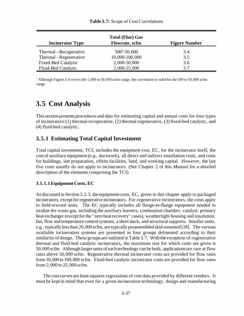
Incinerator TypeTotal (Flue) GasFlowrate, scfm Figure Number
Thermal - RecuperativeThermal - RegenerativeFixed-Bed CatalyticFluid-Bed Catalytic
500 -50,000a
10,000-100,0002,000-50,0002,000-25,000
3.43.53.63.7
Although Figure 3.4 covers the 1,000 to 50,000 scfm range, the correlation is valid for the 500 to 50,000 scfma
range.
Table 3.7: Scope of Cost Correlations
3.5 Cost Analysis
This section presents procedures and data for estimating capital and annual costs for four typesof incinerators:(1) thermal-recuperative, (2) thermal regenerative, (3) fixed-bed catalytic, and(4) fluid-bed catalytic.
3.5.1 Estimating Total Capital Investment
Total capital investment, TCI, includes the equipment cost, EC, for the incinerator itself, thecost of auxiliary equipment (e.g., ductwork), all direct and indirect installation costs, and costsfor buildings, site preparation, offsite facilities, land, and working capital. However, the lastfive costs usually do not apply to incinerators. (See Chapter 2 of this Manual for a detaileddescription of the elements comprising the TCI)
3.5.1.1 Equipment Costs, EC
As discussed in Section 3.2.3, the equipment costs, EC, given in this chapter apply to packagedincinerators, except for regenerative incinerators. For regenerative incinerators, the costs applyto field-erected units. The EC typically includes all flange-to-flange equipment needed tooxidize the waste gas, including the auxiliary burners, combustion chamber, catalyst, primaryheat exchanger (except for the "zero heat recovery" cases), weathertight housing and insulation,fan, flow and temperature control systems, a short stack, and structural supports. Smaller units,e.g., typically less than 20,000 scfm, are typically preassembled skid-mounted [18]. The variousavailable incineration systems are presented in four groups delineated according to theirsimilarity of design. These groups are outlined in Table 3.7. With the exception of regenerativethermal and fluid-bed catalytic incinerators, the maximum size for which costs are given is50,000 scfm. Although larger units of each technology can be built, applications are rare at flowrates above 50,000 scfm. Regenerative thermal incinerator costs are provided for flow ratesfrom 10,000 to 100,000 scfm. Fluid-bed catalytic incinerator costs are provided for flow ratesfrom 2,000 to 25,000 scfm.
The cost curves are least-squares regressions of cost data provided by different vendors. Itmust be kept in mind that even for a given incineration technology, design and manufacturing

3-38
procedures vary from vendor to vendor, so that costs may vary. As always, once the studyestimate is completed, it is recommended that more than one vendor be solicited for a moredetailed cost estimate.
The additional expense of acid gas clean-up or particulate control is not treated in thissection. The equipment cost of a gas absorber to remove any acid gases formed in theincinerator can be quite large, sometimes exceeding the equipment cost of the incinerator itselfeven for simple packed tower scrubbers [19]. For more complex absorbers that include venturiscrubbers instead of, or in addition to, packed beds, the cost of the scrubber alone may be up to4 times that of the incinerator [11]. These more complex absorbers are sometimes necessarywhen particulates, in addition to acid gases, must be removed from the flue gas. (Note: Chapter9 of the Manual provides data and procedures for sizing and costing gas absorbers.)
Thermal Incinerators Among the thermal units, the direct flame (0% energy recovery) andrecuperative systems are treated together because the various levels of energy recovery areachieved simply by adding heat exchanger surface area. Costs for these units were provided byseveral vendors [12,20,21]. The EC of these units are given as a function of total volumetricthroughput, Q , in scfm. "Q ", is the total volume of the gaseous compounds exiting thetot tot
combustion chamber; it is identical to the term, "Q ," used in Figures 3.1 and 3.3. This includesfithe combustion products, nitrogen, unburned fuel and organics, and other constituents. (SeeFigure 3.4). Note that costs are given free on board (F.O.B.) in April

3-39
Figure 3.4. Equipment Costs of Thermal Incinerators, Recuperative

EC 10294Q 0.2355tot HR 0%
EC 13149Q 0.2609tot HR 35%
EC 17056Q 0.2502tot HR 50%
EC 21342Q 0.2500tot HR 70%
EC 2.204 × 10⁵ 11.57 Qtot
EC 1105Q 0.5471tot HR 0%
EC 3623Q 0.4189tot HR 35%
EC 1215Q 0.5575tot HR 50%
EC 1443Q 0.5527tot HR 70%
*For information on escalating these and the other incinerator prices to more current dollars, refer to the EPA report Escalation Indexes for Air Pollution Control Costs and updates thereto, all of which are installed on the OAQPS Technology Transfer Network (CTC Bulletin Board).
3-40
(3.24)(3.25)(3.26)(3.27)
3.28
(3.29)(3.30)(3.31)(3.32)
1988 dollars . Based on a least-squares regression analysis, a log-log relationship between*
throughput and EC was found for a given level of energy recovery (HR) over the flow rate rangefrom 500 to 50,000 scfm. These relationships are as follows:
The regenerative (or excess enthalpy) systems provide up to 95 percent heat recovery at theexpense of higher capital costs. Their unique design [22,23], which combines the heatexchanger and reactor, is substantially different from traditional thermal units and is thereforetreated separately in Figure 3.5. The ECs of these systems are given as an approximately linearfunction of total flow rate over a 10,000 to 100,000 scfm range by the following equation:
Again, the higher capital costs of these units can be substantially offset by the substantialsavings in auxiliary fuel costs.
Catalytic Incinerator The EC for a catalytic incinerator is a function of the type of catalystcontacting pattern used and the total gas flow rate, Q , for a given level of energy recovery.totThere are three types of contacting configurations used in catalytic systems: fixed-bed, catalyticmonolith, and fluid-bed. The EC for the first two are generally comparable and are given inFigure 3.6. The data provided by several vendors [12,20,21,24] exhibited curvilinearrelationships with Q for each of the energy recovery rates. Least squares regressions of thetot
data yielded the following correlations for total flow rates between 2,000 and 50,000 scfm:

3-41
Figure 3.5. Equipment Costs of Thermal Incinerators, Regenerative

EC 8.48 x 10⁴ 13.2Qtot HR 0%
EC 8.84 x 10⁴ 14.6Qtot HR 35%
EC 8.66 x 10⁴ 15.8Qtot HR 50%
EC 8.39 x 10⁴ 19.2Qtot HR 70%
3-42
(3.33)(3.34)(3.35)(3.36)
Fluid-bed catalytic incinerators afford certain advantages over fixed-bed catalyst units inthat they tolerate waste streams with (1) higher heating values, (2) particulate contents, and (3)chlorinated species. For this enhanced flexibility of feed streams, a higher capital cost isincurred, as indicated by the EC shown in Figure 3.7. The data shown were provided by vendors[11,19] and exhibited a linear relationship over the range of flow rates from 2,000 to 25,000scfm. They can be approximated by the following equations:

3-43

3-44
Figure 3.6. Equipment Costs of Catalytic Incinerators, Fixed-Bed

3-45
A comparison of the thermal, catalytic fixed-bed, and catalytic fluid-bed systems with 50percent energy recovery is shown in Figure 3.8.
3.5.1.2 Installation Costs
As explained in Chapter 2, the purchased equipment cost, PEC, is calculated by taking the sumof the EC and the cost of auxiliary equipment (e.g., ductwork), taxes, freight, andinstrumentation. Average values of direct and indirect installation factors [25] to be applied tothe PEC are given in Table 3.8 for both recuperative thermal and fixed- and fluid-bed catalyticincinerators.
Table 3.9 shows the itemized installation costs that are obtained when these installation factorsare applied to the PECs for the example incinerators. Depending on the site conditions, theinstallation costs for a given incinerator could deviate significantly from costs generated bythese average factors. Vatavuk and Neveril [25] provide some guidelines for adjusting theaverage installation factors to account for other-than-average installation conditions. For unitshandling total gas flow rates lower than 20,000 scfm the installation costs are minimal,amounting normally to only utility tie-ins (electrical and, if necessary, combustion or dilutionair). The installation costs for these smaller incinerators would be 20 to 25 % of the PEC.Smaller units may be installed on the roofs of manufacturing buildings rather than at groundlevel. In such cases the installation factors could be as high as (or higher than) the factorsshown in Table 3.8, even though the units would be "packaged".
3.5.2 Estimating Total Annual Cost
The total annual cost (TAC) is the sum of the direct and indirect annual costs. The TAC forboth example systems is given in Table 3.10, alone with suggested factors for calculating them.
3.5.2.1 Direct Annual Costs
Direct annual costs for incinerators include labor (operating and supervisory), maintenance(labor and materials), fuel, electricity, and (in catalytic units) replacement catalyst. For thermaland catalytic units, the fuel usage rate is calculated as shown in Sections 3.4.2 and 3.4.3,respectively where natural gas (methane) is assumed to be the fuel. (Other fuels could be usedf o r t h e r m a l u n i t s . )

3-46
Figure 3.7. Equipment Costs of Catalytic Incinerators, Fluid-Bed

3-47
Figure 3.8: Equipment Costs Comparison of Incinerator Types

3-48
Cost Item Factor
Direct CostsPurchased equipment costs
Incinerator (EC) + auxiliary equipmentb
Instrumentationc
Sales taxesFreight
Purchased equipment cost, PEC
As estimated, A0.10 A0.03 A
0.05 AB = 1.18 A
Direct installation costsFoundations & supportsHandling & erectionElectricalPipingInsulation for ductworkd
PaintingDirect installation cost
0.08 B0.14 B0.04 B0.02 B0.01 B0.01 B0.30 B
Site preparationBuildings
As required, SPAs required, Bldg
Total Direct Cost, DC 1.30 B + SP + Bldg.
Indirect Costs (installation)EngineeringConstruction and field expensesContractor feesStart-upPerformance testContingencies
Total Indirect Cost, IC
0.10 B0.05 B0.10 B0.02 B0.01 B0.03 B0.31 B
Total Capital Investment = DC + IC 1.61 B + SP + Bldg.
Reference [25]a
Ductwork and any other equipment normally not included with unit furnished by incinerator vendor.b
Instrumentation and controls often furnished with the incinerator, and those often included in the EC.c
If ductwork dimensions have been established, cost may be estimated based on $10 to $12/ft of surface for fluidd 2
application. (Alternatively, refer to Chapter 10 of this Manual. Fan housings and stacks may also be insulated.
Table 3.8. Capital Cost Factors for Thermal and Catalytic Incineratorsa

3-49

3-50
Table 3.9. Capital Costs for Thermal and Catalytic IncineratorsExample Problem

3-51
Cost Item Suggested Factor Unit Costa Thermal Fluid-BedCatalyst
Direct Annual Costs , DCb
Operating LaborOperatorSupervisor
0.5 h/shift15% of operator
$12.95/h—
6,480972
6,480972
Operating Materials —
MaintenanceLaborMaterial
0.5 h/shift100% ofmaint. labor
$14.25/h—
7,1307,130
7,1307,130
Catalyst replacement 100% of catalystreplaced ea. 2 yr.
$650/ft for3
metal oxide0 15,100
UtilitiesNatural GasElectricity
Total DC
——
$3.30/kft3
$0.059/kWh264,500 36,500$321,200
63,400 44,200$144,400
Indirect Annual Costs, ICOverhead 60% of sum of
operating, supr.,& maint. labor &maint. materials.
— 13,000 13,000
Administrative chargesProperty taxesInsuranceCapital recoveryc
Total Annual Cost (rounded)
2% TCI1% TCI1% TCICRF [TCI- 1.08(Cat. Cost)]
————
9,6504,8304,830
68,800 $101,100
$422,000
17,8008,9008,900
122,700
$171,300
$316,000
1988 dollarsa
Assumes 8.000 h/yrb
The capital recovery cost factor, CRF, is a function of the catalyst or equipment life (typically, 2 and 10 years, respectively)c
and the opportunity cost of the capital (i.e., interest rate). For example, for a 10-year equipment life and a 7% interest rate,CRF = 0.1424.
Table 3.10. Annual Costs for Thermal and Catalytic IncineratorsExample Problem

Powerfan
1.17 × 10 4QwiP
Powerfan1.17 × 10 4(20,900 acfm) (19 inches water)
0.6077.4 kW
*A fluid-bed catalytic incinerator is used because the waste gas contains a chlorinated compound which would poison the catalyst in a fixed-bed incinerator.
**Computed from inlet waste-gas flow rate (20,000 scfm) at preheater inlet temperature (100 F).
3-52
(3.37)
Equipment Type Energy Recovery, % P, in. H O2
Thermal IncineratorsCatalytic Fixed-bed IncineratorsCatalytic Fluid-bed IncineratorsHeat Exchangers" "" "
000355070
46
6-104815
Table 3.11. Typical Pressure Drop Across Selected Equipment
The electricity costs are primarily associated with the fan needed to move the gas throughthe incinerator. The power (in kilowatts) needed to move a given inlet volumetric flow rate ofair (Qwi per Sections 3.4.2 and 3.4.3) at a total flange-to-flange pressure drop of P inches ofwater and combined motor/fan efficiency, , is adapted from Equation 2.7, as follows:
Fan efficiencies vary from 40 to 70 percent [15] while motor efficiencies are usually 90 percent.
The total pressure drop across an incinerator system depends on the number and types ofequipment elements included in the system and on design considerations. The estimation ofactual pressure drop requirements involves complex calculations based on the specific system'swaste gas and flue gas conditions and equipment used. For the purposes of this section,however, the approximate values shown in Table 3.11 can be used.
For the example cases, we will assume 8,000 hours per year operation and a 60% efficiencyfor the fan and motor together. Using pressure drops of 4 and 8 inches of water, respectively,for the thermal and fluid-bed catalytic incinerators , and adding the pressure drop of 15 inches*
of water for 70% heat recovery, the fan power requirements can be calculated as follows:
Thermal Incinerator**

Powerfan
1.17 × 10 4(20,900 acfm) (23 inches water)0.60
93.7 kW
Electricity Cost (Thermal) 77.4 kW × 8,000 hours /yr × $0.059/kWh$36,500 per yr
Electricity Cost (Catalytic) 93.7 kW × 8,000 hours /yr × $0.059/kWh$44,200 per yr
Annual Catalyst Replacement Cost 39 ft3 × 650$
ft3× 0.5531 × 1.08
$15,100 per year
3-53
Catalytic Incinerator
The annual electricity costs would be the products of these usages, the annual operatinghours, and the electricity cost ($/kWh), or:
The catalyst replacement costs and scheduling are highly variable and depend on the natureof the catalyst, the amount of "poisons" and particulates in the gas stream (including theauxiliary fuel), the temperature history of the catalyst, and the design of the unit. It isimpossible to predict the costs in a general sense. However, noble metal monolith catalystsoperating on pure hydrocarbon gases in air will last longer than fluid-bed base metal catalystsoperating on chlorinated hydrocarbons in air. Noble metal catalysts are also more expensivethan base metal oxide catalysts. The catalyst life for many field units is from 1 to 4 years. Thecost, in April 1988 dollars, of the replacement catalyst must be obtained from the vendor, butit may be estimated at $3,000/ft for noble metal catalysts and $650/ft for base metal oxide3 3
catalysts. For the example case, the catalyst is a base metal oxide because the waste gascontains a chlorinated compound. We will assume a two year catalyst life. Knowing that thecatalyst volume is 39 ft (Section 3.4.3) and using a cost of $650/ft and a capital recovery factor3 3
of 0.5531 (2-year life at a 7% interest rate), the annual expense for catalyst replacement is
(The " 1.08" factor covers the freight and sales tax for the replacement catalyst.)
To calculate the fuel or electricity annual cost, multiply the fuel usage rate (scfm) or theelectricity usage rate (kW) by the total hours per year of operation (e.g., 333 d/yr x 24 h/d =8,000 h/yr) and by the appropriate unit cost (e.g., $/scfm for fuel and $/kWh for electricity).
For the example cases, the fuel costs can be calculated from the fuel usage rates and thenatural gas unit cost of $0.00330/scf. For the thermal incinerator example, the annual fuel costis calculated as follows:
Annual Fuel 0.00330$
scf× 167
scfmin
× 60minhr
× 8,000hryr
Cost, Thermal $264,500 per year
3-54
For the catalytic incinerator example. the annual fuel cost is found similarly:
Annual Fuel Cost, Catalytic = $63,400 per year
Operating and maintenance labor are estimated as 0.5 hours per 8-hour shift each,supervisory labor at 15% of operating labor, and maintenance material as 100% of maintenancelabor.
3.5.2.2 Indirect Annual Costs
The indirect (fixed) annual costs include capital recovery, overhead, and property taxes,insurance, and administrative (G&A) charges. The last three of these can be estimated at 1%,1%, and 2% of the total capital investment, respectively. The system capital recovery cost isbased on an estimated 10-year equipment life. (See Section 2 for a thorough discussion of thecapital recovery cost and the variables that determine it.) The system capital recovery cost isthe product of the system capital recovery factor (CRF) and the total capital investment (TCI)less the purchased cost of the catalyst (C x 1.08 where the 1.08 is for freight and sales tax).catThese values calculated for the example cases are given in Table 3.10.
3.5.3 Cost Comparison for Example Case
The example VOC stream defined in Section 3.4.1 serves to illustrate some typicalcharacteristics of thermal and catalytic systems. The total annual costs shown in Table 3.10show that the catalytic system's auxiliary fuel costs are significantly lower than those of thethermal unit. The disparity is enough to offset the higher capital costs of the catalyticincinerator over the assumed 10-year lifetime of the units. Two factors that should be noted inthe comparison of these two systems are (1) the 98 percent level of destruction met by thethermal incinerator may be difficult to reach by the catalytic system (this may be important insome cases), and (2) the example waste stream is of particularly low heating value (4 Btu/scf)which favors the catalytic system due to the lower auxiliary fuel requirements.
3.6 Acknowledgements
The authors gratefully acknowledge the following companies for contributing data to thischapter:
Peabody Engineering (Stamford, CT)
3-55
Combustion Engineering - Air Preheater, Inc. (Wellsville, NY)
TEC Systems, Inc. (DePere, WI)
Air Research, Inc. (ARI) (Palatine, IL)
Energy Development Associates (EDA) (Itasca, IL)
Pillar Technologies, Inc. (Hartland, WI)
Huntington Energy Systems, Inc. (Union, NJ)
Regenerative Environmental Equipment Co. (REECO) (Morris Plains, NJ)
Englehard Corp. (Edison, NJ)

3-56
Appendix 3A
Properties of SelectedCompounds

3-57
CompoundMolecular
WeightLEL ,a
vol. %UEL ,b
vol. %
MethaneEthanePropaneButanePentaneHexaneOctaneNonaneDecane
16.0430.0744.0958.1272.1586.17
114.23128.25142.28
5.003.002.121.861.401.180.950.830.77
15.0012.509.358.417.807.40
EthylenePropylene
28.0542.08
2.752.00
28.6011.10
Acetylene 26.04 2.50 80.00
Cyclohexane 84.16 1.26 7.75
BenzeneToluene
78.1192.13
1.401.27
7.106.75
*Reference [14]Lower Explosive Limita
Upper Explosive Limitb
Table 3.12. Limits of Flammability of Combustible Organic Compounds in Air atAtmospheric Pressure, Room Temperature*

Cp a bT cT 2 dT 3 ; T in K
Cpm
T2
T1
CpdT
(T2 T1)Cp in calories/g moles oK Btu/lb mole oR
3-58
Table 3.13: Molar Heat Capabilities of Gases at Zero Pressure*
TemperatureCompound a b x 10 c x 10 d x 10 Range, K2 6 9
Methane 4.750 1.200 0.3030 -2.630 273-1500Ethane 1.648 4.124 -1.530 1.740 273-1500Propane -0.966 7.279 -3.755 7.580 273-1500Butane 0.945 8.873 -4.380 8.360 273-1500Pentane 1.618 10.85 -5.365 10.10 273-1500Hexane 1.657 13.19 -6.844 13.78 273-1500
Cyclopentane -12.957 13.087 -7.447 16.41 273-1500Cyclohexane -15.935 16.454 -9.203 19.27 273-1500
Benzene -8.650 11.578 -7.540 18.54 273-1500Toluene -8.213 13.357 -8.230 19.20 273-1500
Nitrogen 6.903 -0.03753 0.1930 -0.6861 273-1800Oxygen 6.085 0.3631 -0.1709 0.3133 273-1800Air 6.713 0.04697 0.1147 -0.4696 273-1800Carbon dioxide 5.316 1.4285 -0.8362 1.784 273-1800
W444444444444444444444444444444444444444444444444444444444444444444* Reference [26]

3-59
Table 3.14 Heats of Combustion of Selected Gaseous Organic Compounds, - h , at 25 Cc
and constant pressure to form gaseous water and carbon dioxide.*
Molecular - hc
Compound Weight cal/g. Btu/lb
Methane 16.04 11,953.6 21,502Ethane 30.07 11,349.6 20,416Propane 44.09 11,079.2 19,929Butane 58.12 10,932.3 19,665Pentane 72.15 10,839.7 19,499Hexane 86.17 10,780.0 19,391Octane 114.23 10,737.2 19,256Nonane 128.25 10,680.0 19,211Decane 142.28 10,659.7 19,175
Ethylene 28.05 11,271.7 20,276Propylene 42.08 10,942.3 19,683
Cyclopentane 70.13 10,563.1 19,001Cyclohexane 84.16 10,476.7 18,846
Benzene 78.11 9,698.4 17,446Toluene 92.13 9,784.7 17,601
W44444444444444444444444444444444444444444444444444444444444444444444*Reference [15]

3-60
Appendix 3B
Design Procedure for Non-RecuperativeThermal Incinerators
3-61
Not all thermal incinerators are equipped with recuperative heat exchangers to transferenergy from the flue gas stream to the incoming waste gas stream. These non-recuperative unitsuse other mechanisms to recovery flue gas energy. One of these types is the regenerativeincinerator. As discussed in Section 3.2.1.3, a regenerative incinerator accomplishes energyrecovery by conveying the flue gas through a ceramic bed which captures a portion of thestream's enthalpy. After a switching mechanism is engaged, the incoming waste gas passesthrough this hot bed and is warmed to its ignition temperature. This process is illustrated inFigure 3.2.
While we can determine the stream inlet and outlet temperatures for a recuperative heatexchanger fairly accurately, we cannot always do so for a regenerative incinerator bed. For onething, these beds do not behave like typical heat exchangers. The bed temperature profiles areoften difficult to predict. More importantly, because regenerative incinerators do not operateat steady state conditions, the temperatures within the beds and many other parts of the unit varywith time. For that reason, it is more convenient to view the entire regenerative incinerator asa "black box" into which waste gas and auxiliary fuel flow and from which flue gas emanates.Around this black box we may make mass and energy balances. In this way, we need not makeany assumptions about what occurs inside the incinerator regarding temperatures, flowrates, orother stream parameters.
However, to determine the auxiliary fuel requirement for regenerative incinerators via theprocedure shown in this appendix we have to make two key assumptions, viz.: (1) thetemperatures and flowrates of all streams entering and leaving the incinerator are at steady stateand (2) the combustion temperature (and by inference, the heat loss fraction) are constant aswell. The other assumptions will be addressed in the following design steps:
Steps 1 to 4: These are the same as those for thermal recuperative and catalytic incinerators.(See Section 3.4.1.)
Step 5t - Establish the incinerator operating temperature: Because their designs are moreresistant to thermal stresses and because they can achieve very high heat recoveries,regenerative incinerators are usually operated at higher temperatures than recuperative units. Consequently, higher VOC destruction efficiencies are achieved. Operating temperatures of1800 to 2000 F are typical.
Step 6t - Calculate the waste gas temperature at the exit of the preheater: As explainedabove, regenerative incinerators do not employ preheaters. The preheating is done by andwithin the ceramic beds. Moreover, because the mass and energy balances are made around theentire unit, we do not need to know the temperature of the preheated waste gas to calculate theauxiliary fuel requirement. Step 7t - Calculate the auxiliary fuel requirement, Q : Because a regenerative incineratoraf
recovers nearly all of the energy from the combustion (flue) gas, its auxiliary fuel requirementis usually lower than that for a recuperative incinerator. However, as discussed above, this fuelrequirement is determined via mass and energy balances taken around the entire unit, not justthe combustion chamber. Consider the following diagram:

3-62
Flue gas T * (fo) * R +)))))))))))))))))))))))))), * * * Incinerator unit * Aux. fuel S)))))Q * (any type) * S)))) Waste
(af) * * gas * * (wi) .))))))))))))))))))))))))))-
Taking mass and energy balances around the incinerator, we obtain: Mass balance:
Mass in = Mass out
Mass fuel + Mass waste gas = Mass flue gas
Q + Q = Q (3B-1)af af wi wi fo fo
Energy balance:
Next, we take an energy balance around the incinerator unit:
Energy in - Energy out + Energy generated = 0
The terms of the energy balance equation are the inlet waste gas and outlet flue gasenthalpies (H and H , respectively), the energy loss (H ), and the waste gas VOC and fuelwi fo L(natural gas) heat contents (H and H , in turn):cwi caf
H - (H + H ) + (H + H ) = 0 (3B-2)wi fo L cwi caf
The variables comprising each of the terms in this energy balance equation are listed inTable 3.6. They are:
H = Q C (T - T )wi wi wi pmwi wi ref
H = Q C (T - T )fo fo fo pmfo fo ref
H = Q C (T - T )L fi fi pmfi fi ref
H = Q (- h )cwi wi wi cwi
H = Q (- h )caf af af caf

3-63
where: = energy loss from combustion chamber (fractional) T = combustion temperature ( F)fi
We next substitute these variables into eq. (3B-2) and solve for the fuel mass rate ( Q ).af afWhen doing so, we make the following assumptions:
The streams flowing to and from the incinerator are at steady state conditions.
The auxiliary air requirements are zero.
The ambient, reference, and fuel inlet temperatures are equal (77 F). (This assumptionresults in the inlet fuel stream having a zero enthalpy.)
The heat capacities of the gas streams to and from the unit are approximately the same,regardless of composition.
The mean heat capacities of the streams above the reference temperature (77 F) areapproximately equal, regardless of temperature. Further, the mean heat capacity of thewaste gas/flue gas stream entering/leaving the incinerator is evaluated at the average of theinlet (T ) and combustion (T ) temperatures. That is, C = C = C = C . wi fi pmwi pmfi pmfo pm
When we do all this, we get the following expression:
Q C (T - T ) - [ Q C (T - T ) + Q C (T - T )] + wi wi pm wi ref fo fo pm fo ref fi fi pm fi ref(Energy in) (Energy out)
[ Q (- h ) + Q (- h )] = 0wi wi cwi af af caf
(Energy generated)
Substitution for Q per eq. 3B-1 above yields:fo fo
{ Q C (T -T )} - { C ( Q + Q )(T -T ) +wi wi pm wi ref pm af af wi wi fi ref
C ( Q + Q )(T -T )} + { Q (- h ) + Q (- h )} = 0 pm af af wi wi fo ref wi wi cwi af af caf
Finally, solving for Q , the auxiliary fuel mass rate (lb/min):af af
Q {C [ (T - T ) + (T - T )] - (- h )}wi wi pm fi ref fo wi cwiQ = ))))))))))))))))))))))))))))) (3B-3)af af{(- h ) - C [ (T - T ) + (T - T )]}caf pm fi ref fo ref
Equation (3B-3) provides the auxiliary fuel requirement for any type of thermal incinerator,as it is independent of any intermediate variables, such as the temperature of the preheatedwaste gas. Clearly, this equation can be used with regenerative incinerators, as long as theabove-stated assumptions hold.

3-64
The heat loss fraction ( ) will vary according to the incinerator type, how the incineratorcomponents are configured in the unit, the construction materials, the type and amount ofinsulation, and other factors. For instance, for recuperative incinerators, is approximately0.10. The for regenerative incinerators is considerably lower, however. There are two reasonsfor this. First, the components of a regenerative incinerator—combustion chamber, ceramicbeds, etc.—are housed in a single enclosure, while in a recuperative incinerator the combustionchamber, heat exchanger, and interconnecting ductwork are housed separately, thus offeringmore heat transfer area. Second, because regenerative units are lined with ceramic, they arebetter insulated than recuperative incinerators.
To gain an estimate of this heat loss fraction, we contacted two regenerative incineratorvendors. [27,28] Based on the heat loss data that they supplied, we calculated values rangingfrom 0.002 to 0.015 (0.2 to 1.5%). These values varied according to the incineratorconfiguration (vertical or horizontal), the waste gas flow rate, the ambient temperature, and thewind speed.
Step 8t - Verify that the auxiliary fuel requirement is sufficient to stabilize the burnerflame: As explained in Section 3.4.2, only a small amount (< 5% of the total energy input) isneeded to stabilize the burner flame. With recuperative incinerators, the auxiliary fuelrequirement is usually much larger than the burner stabilization requirement, so that thisconstraint rarely comes into play. With regenerative incinerators, however, the auxiliary fuelrequirement may be as low or lower than the fuel needed to stabilize the burner. Therefore, itis important to compare these two requirements. This comparison is made via equations 3.19and 3.20. If the auxiliary fuel is less, the minimum fuel requirement would be set at 5% of thetotal energy input.
Step 9t - Calculate the flue gas volumetric flow rate, Q : As with thermal recuperativefiincinerators, the regenerative incinerator flue gas flow rate is the rate used to size and cost theunit. Measured at standard conditions (1 atmosphere and 77 F), Q is the sum of the inletfiwaste gas (Q ) and fuel (Q ) flow rates. But since Q for regenerative units is small comparedwi af afto Q , the waste gas and flue gas flows should be virtually identical. wi

3-65
References
[1] Prudent Practices for Disposal of Chemicals from Laboratories, National AcademyPress, Washington, D.C., 1983.
[2] Memo from Mascone, D.C., EPA, OAQPS, to Farmer, J. R., OAQPS, EPA, June 11,1980, Thermal Incinerator Performance for NSPS.
[3] Memo from Mascone, D.C., EPA, OAQPS, to Farmer, J. R., OAQPS, EPA, July 22,1980, Thermal Incinerator Performance for NSPS, Addendum.
[4] Memo from Mascone, D.C., EPA, OAQPS, to Farmer, J. R., OAQPS, EPA, August 22,1980, Thermal Incinerators and Flares.
[5] Letter from Thomas Schmidt (ARI International, Palatine, IL) to William M. Vatavuk(EPA, OAQPS, Research Triangle Park, NC), August 16, 1989.
[6] Weldon, J. and S. M. Senkan, Combustion Sci. Technol., 1986, 47.
[7] Manning, P., Hazard Waste, 1984, 1(1).
[8] Pope, D., Walker, D. S., Moss, R. L., Atmos. Environ., 1976, 10.
[9] Musick, J. K., and F. W. Williams, Ind. Eng. Chem. Prod. Res. Dev., 1974, 13(3).
[10] Letter from Robert M. Yarrington (Englehard Corporation, Edison, NJ) to William M.Vatavuk (EPA, OAQPS, Research Triangle Park, NC), August 14, 1989.
[11] Personal Communication from Bill Sheffer (ARI, Inc., Palatine, IL) to Donald R. vander Vaart (RTI, Research Triangle Park, NC), March 30, 1988.
[12] Personal Communication from Ralph Stettenbenz (Combustion Engineering, AirPreheater, Inc., Wellsville, NY) to Donald R. van der Vaart (RTI, Research TrianglePark, NC), March 23, 1988.
[13] Grelecki, C., Fundamentals of Fire and Explosion Hazards Evaluation, AIChE TodaySeries, New York, 1976.

3-66
[14] Weast, R.C. (ed.), CRC Handbook of Chemistry and Physics, 49th ed., CRC Press,Cleveland, Ohio, 1968.
[15] Perry, R. H. and C. H. Chilton(eds.), Chemical Engineers Handbook, 5th ed., McGraw-Hill, New York, 1973.
[16] Personal Communication from Robert Yarrington (Englehard Corp., Edison, NJ) toWilliam M. Vatavuk (EPA, OAQPS, Research Triangle Park, NC), June 6, 1989.
[17] Personal Communication from Thomas Schmidt (ARI International, Palatine, IL) toWilliam M. Vatavuk (EPA, OAQPS, Research Triangle Park, NC), June 7, 1989.
[18] Githens, R. E. and D. M. Sowards, Catalytic Oxidation of Hydrocarbon Fumes, PB-299132, National Technical Information Service, Springfield, VA.
[19] Personal Communication from Andrew Jones (Energy Development Associates, Itasca,IL) to Donald R. van der Vaart (RTI, Research Triangle Park, NC), March 4, 1988.
[20] Personal Communication from C. L. Bumford (Peabody Engineering, Stamford, CT) toDonald R. van der Vaart (RTI, Research Triangle Park, NC), March 28, 1988.
[21] Personal Communication from C. M. Martinson (TEC Systems, DePere, WI) to DonaldR. van der Vaart (RTI, Research Triangle Park, NC), March 28, 1988.
[22] Personal Communication from Ronald J. Renko (Huntington Energy Systems, Inc.,Union, NJ) to Donald R. van der Vaart (RTI, Research Triangle Park, NC), March 16,1988.
[23] Personal Communication from James H. Mueller (Regenerative EnvironmentalEquipment Co., Inc., Morris Plains, NJ) to Donald R. van der Vaart (RTI, ResearchTriangle Park, NC), January 13, 1988.
[24] Personal Communication from Robert Hablewitz (Pillar Technologies, Hartland, WI)to Donald R. van der Vaart (RTI, Research Triangle Park, NC), March 20, 1988.
[25] Vatavuk, W. M. and R. Neveril, "Estimating Costs of Air Pollution Control Systems,Part II: Factors for Estimating Capital and Operating Costs", Chemical Engineering,November 3, 1980, pp. 157-162.
[26] Kobe, K. A. and associates, "Thermochemistry for the Petrochemical Industry",Petroleum Refiner, Jan. 1949 through Nov. 1954.
[27] Letter from William M. Vatavuk (EPA, OAQPS, Research Triangle Park, NC) to GeraldSchrubba (Salem Engelhard, South Lyon, MI), September 22, 1992.

3-67
[28] Letter from William M. Vatavuk (EPA, OAQPS, Research Triangle Park, NC) to RodPennington (REECO/Research Cottrell,Somerville, NJ), September 22, 1992.