three-dimensional subsurface imaging synthetic …/67531/metadc665219/m2/1/high...three-dimensional...
TRANSCRIPT
Three-Dimensional Subsurface Imaging Synthetic Aperture Radar
Authors:
E. Wuenschel
Contractor:
Mirage Systems, Inc. 232 Java Drive Sunnyvale, California 94089
Contract Number:
DE-AR2 1 -93MC30357
Conference Title:
Environmental Technology Development Through Industry Partnership
Conference Location:
Morgantown, West Virginia
Conference Dates:
October 3-5, 1995
Conference Sponsor:
U.S. Department of Energy, Office of Environmental Management, Morgantown Energy Technology Center
Portions of this document may be illegible in electronic image produck h a g s are produced from the best available original doaxmest.

DISCLAIMER
This report was prepared as an account of work sponsored by an agency of the United States Government. Neither the United States Government nor any agency thereof, nor any of their employees, makes any warranty, express or implied, or assumes any legal liability or responsibility for the accuracy, completeness, or usefulness of any information, apparatus, product, or process disclosed, or represents that its use would not infringe privately owned rights. Reference herein to any specific commercial product, process, or service by trade name, trademark, manu- facturer, or otherwise does not necessarily constitute or imply its endorsement, recommendation, or favoring by the United States Government or any agency thereof. The views and opinions of authors expressed herein do not necessarily state or reflect those of the United States Government or any agency thereof.
This report has been reproduced directly from the best available COPY.
Available to DOE and DOE contractors from the Office of Scientific and Technical Information, 175 Oak Ridge Turnpike, Oak Ridge, TN 37831; prices available at (615) 576-8401.
Available to the public from the National Technical Information Service, U.S. Department of Commerce, 5285 Port Royal Road, Springfield, VA 22161; phone orders accepted at (703) 487-4650.
4.6 Three-Dimensional Subsurface Imaging Synthetic Aperture Radar
E. Wuenschel (Mirage @rahul .net; 408-752- 1600) Mirage Systems, Inc.
232 Java Drive Sunnyvale, CA 94089- 13 18
Introduction and Need
Inadequate resources, aggravated by the limited capabilities of existing site characteriza- tion technologies, require that new systems be developed to effectively aid site cleanup. The quantity, condition, and the precise location of buried waste storage containers is often unknown, and is always difficult to assess. Sig- nificant safety hazards may also be present at these sites. Therefore, new non-invasive detec- tion techniques are needed that will be cost effective, user friendly, and have a growth path toward a system capable of accessing remote terrain. These detection methods must be eco- nomical to use and be capable of exploring large land areas quickly with minimal personnel risk. They should provide the precision for identi- fying the size, depth, type, and possibly the condition of the waste containers.
0 bj ectives
The objective of this applied research and development project is to develop a system known as "3-D SISAR." This system consists of a ground penetrating radar with software algorithms designed for the detection, location,
Research sponsored by the U.S. Department of Energy's Morgantown Energy Technology Center, under contract DE-AR21-93MC30357 with Mirage Systems, Inc., 232 Java Drive, Sunnyvale, CA 94089.
and identification of buried objects in the under- ground hazardous waste environments found at DOE storage sites. Three-dimensional maps of the object locations will be produced which can assist the development of remediation strategies and the characterization of the digface during remediation operations. It is expected that the 3-D SISAR will also prove useful for moni- toring hydrocarbon-based contaminant migration.
Approach
The underground imaging technique being developed under this contract utilizes a spotlight mode Synthetic Aperture Radar (SAR) approach which, due to its inherent stand-off capability, will permit the rapid survey of a site and achieve a high degree of productivity over large areas. When deployed from an airborne plat- form, the stand-off technique is also seen as a way to overcome practical survey limitations encountered at vegetated sites.
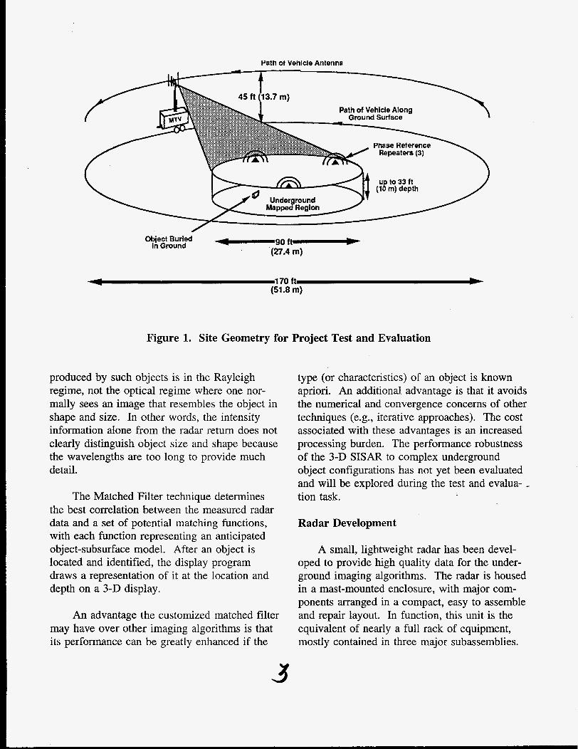
Mirage Systems has designed- and equipped a 22-foot long specially configured trailer, called the Mobile Test Vehicle (MTV), as a sensor sys- tem test platform. The MTV is being used as a mobile laboratory to house the 3-D SISAR in support of field demonstrations of this under- ground imaging technology. Figure 1 illustrates the technique and data collection geometry used for the test and evaluation of the concept.
In a spotlight mode SAR, the area to be surveyed is "spotlighted" or "stared at" as the

radar path forms the synthetic aperture, typically a circle. When compared to SAR strip mapping, the spotlight mode enhances spatial resolution and increases the total energy used to illuminate a patch of the ground.
to plan for the field tests and data collection experiments that are assisting the algorithm development.
The technique provides high coherent inte- gration gain which, when combined with the inherent sensitivity of the frequency modulated, continuous wave (FMCW) signal transmission method, allows a significant improvement in imaging quality. These features are very bene- ficial for subsurface characterization since 1) long wavelengths, which typically produce images with limited spatial resolution, are needed to penetrate the ground, and 2) the subsurface has inherently high propagation losses requiring more available energy for effective ground penetration. The ultra-wide bandwidth of the FMCW signal provides for improved resolution in the depth dimension as well.
Project Description
A matched filter image processing algo- rithm has been developed for the detection and identification of buried objects. Scattering models for several types of buried objects (test spheres, barrels, barrel lids, and pipes) have been constructed from electromagnetics model- ing programs for use with the matched filter algorithm.
A new radar has been developed that pro- duces the high quality data required by the image processing algorithms. A series of tests have been performed to collect data on actual underground objects.
Preceding the software and hardware devel- opment, a series of systems engineering tasks were performed to estimate the radar require- ments, to specify the desired performance, and
Underground Imaging Approach Using Matched Filtering
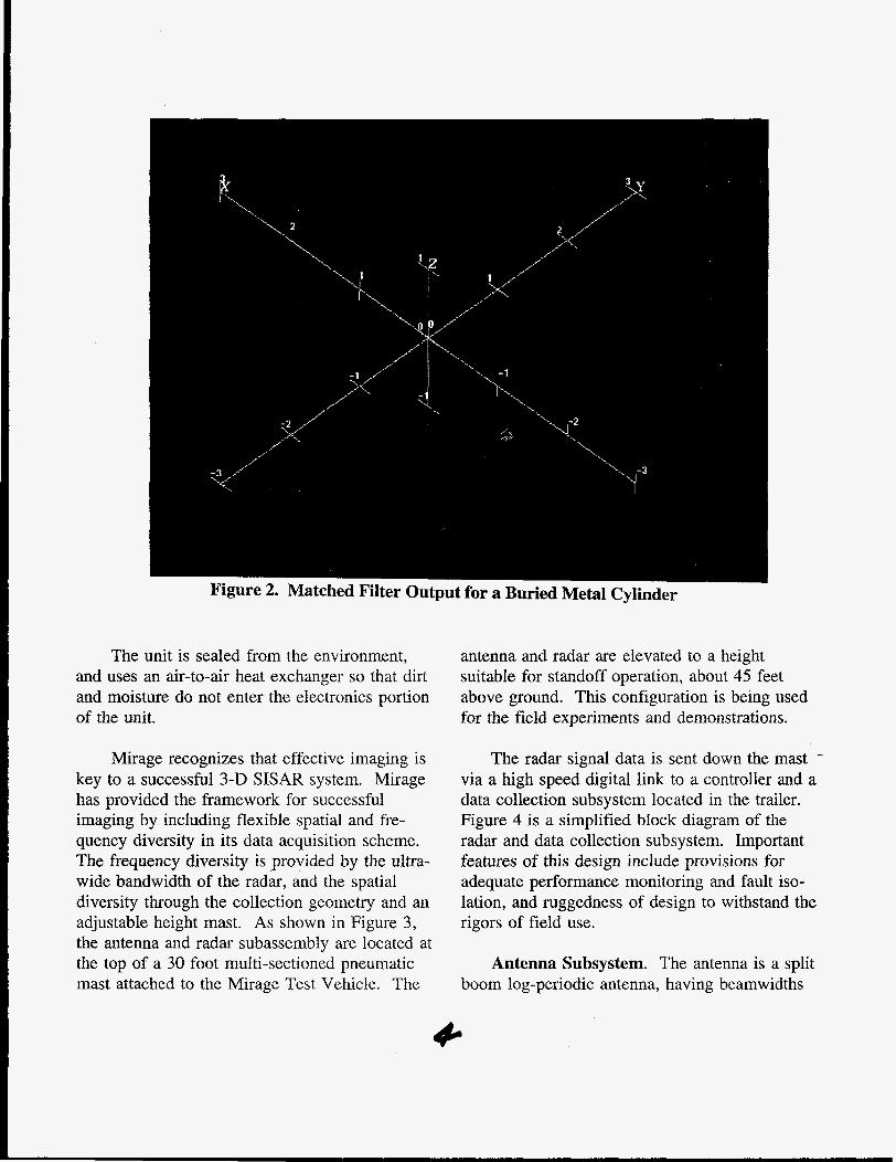
The goal of the 3-D SISAR development is to produce a three-dimensional presentation of the near-surface underground environment that can be applied to the determination of the pres- ence and extent of buried waste. The approach taken by Mirage for this research and develop- ment project is one that produces a representa- tion of buried waste containers based on the unique characteristics of the scattering of elec- tromagnetic waves. This approach has the bene- fit that it searches for a set of unique properties of the radar returns that characterize the shape, dimensions, and orientation of a given buried object. Once an object is located and identified, the imaging software draws a representation of that object in a three-dimensional space that defines the underground mapped region.
Figure 2 is a 3-D display of the matched filter output for a 12" diameter, 3" thick metal cylinder buried at a depth of a foot. The data shows the correlation peak produced by this test object. The center of the image response was located within 10 centimeters in all three dimen-
SISAR to detect and locate shallow buried objects. More information on the test results is provided in the Results section.
sions, demonstrating the capability of the 3-D .- -
There are many facets to producing under- ground images using GPR. One of the major advantages of the matched filter approach is that it overcomes a basic difficulty with other tech- niques that attempt to image the underground environment directly. The difficulty results from the fact that the wavelengths used for under- ground imaging are on the order of the linear dimensions of the object. The scattering
Path ot Vehicle Antenna
Object Buried ft-b in Ground
(27.4 m)
-1 170 ft !b (51.8 m)
Figure 1. Site Geometry for Project Test and Evaluation
produced by such objects is in the Rayleigh regime, not the optical regime where one nor- mally sees an image that resembles the object in shape and size. In other words, the intensity information alone from the radar return does not clearly distinguish object size and shape because the wavelengths are too long to provide much detail.
The Matched Filter technique determines the best correlation between the measured radar data and a set of potential matching functions, with each function representing an anticipated object-subsurface model. After an object is located and identified, the display program draws a representation of it at the location and depth on a 3-D display.
An advantage the customized matched filter may have over other imaging algorithms is that its performance can be greatly enhanced if the
type (or characteristics) of an object is known apriori. An additional advantage is that it avoids the numerical and convergence concerns of other techniques ( e g , iterative approaches). The cost associated with these advantages is an increased processing burden. The performance robustness of the 3-D SISAR to complex underground object configurations has not yet been evaluated and will be explored during the test and evalua--- tion task.
Radar Development
A small, lightweight radar has been devel- oped to provide high quality data for the under- ground imaging algorithms. The radar is housed in a mast-mounted enclosure, with major com- ponents arranged in a compact, easy to assemble and repair layout. In function, this unit is the equivalent of nearly a full rack of equipment, mostly contained in three major subassemblies.
The unit is sealed from the environment, and uses an air-to-air heat exchanger so that dirt and moisture do not enter the electronics portion of the unit.
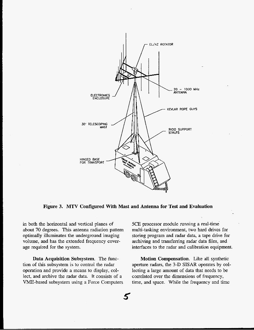
Mirage recognizes that effective imaging is key to a successful 3-D SISAR system. Mirage has provided the framework for successful imaging by including flexible spatial and fre- quency diversity in its data acquisition scheme. The frequency diversity is provided by the ultra- wide bandwidth of the radar, and the spatial diversity through the collection geometry and an adjustable height mast. As shown in Figure 3, the antenna and radar subassembly are located at the top of a 30 foot multi-sectioned pneumatic mast attached to the Mirage Test Vehicle. The
antenna and radar are elevated to a height suitable for standoff operation, about 45 feet above ground. This configuration is being used for the field experiments and demonstrations.
The radar signal data is sent down the mast - via a high speed digital link to a controller and a data collection subsystem located in the trailer. Figure 4 is a simplified block diagram of the radar and data collection subsystem. Important features of this design include provisions for adequate performance monitoring and fault iso- lation, and ruggedness of design to withstand the rigors of field use.
Antenna Subsystem. The antenna is a split boom log-periodic antenna, having beamwidths
20 - 1000 MHz
ELECTRONICS
K N U R ROPE GUYS
30’ TELESCOPING RIGID SUPPORT
HINGED BASE FOR TRANSPORT
Figure 3. MTV Configured With Mast and Antenna for Test and Evaluation
in both the horizontal and vertical planes of about 70 degrees. This antenna radiation pattern optimally illuminates the underground imaging volume, and has the extended frequency cover- age required for the system.
5CE processor module running a real-time multi-tasking environment, two hard drives for storing program and radar data, a tape drive for archiving and transferring radar data files, and interfaces to the radar and calibration equipment.
Data Acquisition Subsystem. The func- Motion Compensation. Like all synthetic aperture radars, the 3-D SISAR operates by col- lecting a large amount of data that needs to be correlated over the dimensions of frequency, time, and space. While the frequency and time
tion of this subsystem is to control the radar operation and provide a means to display, col- lect, and archive the radar data. It consists of a VME-based subsystem using a Force Computers
5

High Speed Digital Data Link
Data Acquisition Subsystem Mast-Mounted Equipment
1 I 1
- - - - - - - - - - - - - - - - - - - - r
I ' 1 1 I VME bus-based Radar '
Transceiver Display
I I
Keyboard
I
I I
Storage I Disc and
8mm Tape
I I
I I ' I Vertically Polarized I Log Periodic
I 1 Antenna Array I
I !- - - - - - - - - - - Optional Ethernet
1 I Color
Printer Silicon
Graphics Workstation
Figure 4. Simplified Block Diagram of the 3-D SISAR
correlation is an internal function of the radar, a set of three external reference repeaters are used to correlate the radar returns in the spatial dimension. The repeaters are positioned around the periphery of the surface of the imaged volume as shown in Figure 1. The signal echo from the repeaters is used to calculate the physi- cal relationship between the radar and the imaged volume of ground. Position location accuracy of approximately 5 centimeters has been demonstrated with update rates of about 30 per second.
Graphics Display Workstation. A Silicon Graphics Indigo 2 model XZ workstation is being used both as a software development
platform and as a means to display and manipulate the processed images. This work- station has the necessary processing speed and graphics capabilities to compute and display the imaging data sets. A three-dimensional digital imaging (3DDI) software program. allows the operator to interact with the large data sets that comprise the images in a meaningful and effi- cient way. It provides the ability to render images in two and three dimensions, rotate and add perspective to images, encode image data with a range of colors, and threshold on intensity values. The program "AVSS" from Advanced Visual Systems is being used as the image display and manipulation capability.
-

Field Testing indicates that the basic assumptions underlying the imaging approach are sound.
Above-ground tests were performed at a large open site in order to evaluate the detection capabilities of the radar, for the development of the precision location estimation subsystem, evaluation of the motion compensation techni- que, and the calibration of the radar transfer function.
Below ground tests were conducted at a prepared site near Jamestown, CA in August 1995 where objects were carefully buried in a large pit. The buried objects included 55-gallon drums, an empty plastic drum, pipes, plates, a sphere, and metal cylinders of various sizes.
Remaining Tasks
The remaining tasks on this project include the completion of the analysis of the data from the field test and evaluation tasks. Additional imaging experiments will continue through the upcoming months on an as needed basis. At the completion of the experimentation, an evaluation demonstration will be scheduled for DOE personnel.
Accomplishments
To date, the experiments with the 3-D SISAR have demonstrated the detection and location of shallow buried objects with a standoff mode of operation. This is a unique accomplishment, since other standoff systems provide only one- or two-dimensional imaging, and other 3-D GPR systems employ ground contacting sensors. Objects were located to within 10 centimeters of their actual positions in three dimensions. The initial results indicate that the radar hardware and position location subsystem are working well, and providing good quality data for the SAR imaging. This also
The 3-D image of a detected buried metal cylinder was shown previously in Figure 2. Although these initial results are for shallow buried objects, work is ongoing to improve the image processing algorithms to increase the processing gain and imaging capability at greater depths. The image-to-clutter ratio for shallow buried objects has been about 10-15 dF3, but this is expected to increase significantly in the near future as improvements are made to the imaging algorithms. This will result in substantial increases in depth penetration capability and clarity of the imaging.
Future Work
The funding of the current contract provides for limited testing. At the completion of the imaging algorithm development, it is envisioned that a subsequent expanded testing phase will be performed. It is suggested that additional testing be performed at a prepared DOE site. This would provide a more complete performance evaluation of the 3-D SISAR under controlled circumstances, and would provide further evaluation of the 3-D SISAR by exploring the potential of the imaging algorithms, learning about real-world remediation situations, and developing approaches for the optimal use of t h e 3-D SEAR during site operations.
Additional work in the image processing area consists of expanding the imaging algo- rithms to handle uneven ground surfaces, streamlining the processing to reduce the pro- cessing time required, a physically smaller antenna system, the integration of Global Posi- tioning satellite data, and eventual installation aboard an airborne platform.
Acknowledgements
Support for this contract has been provided through Mr. Keith Westhusing of the METC Laramie Project Office, the project COR. The
VKOTHA\960101 g
period of performance has been 9/93 through 9/95, and the EM focus areas are Contaminant Plume Containment, Remediation, and Land Stabilization.
8