title particulate matter stack emission compliance … · particulate matter stack emission...
TRANSCRIPT

DOCUMENT RESUME
ID 101 931 SE 017 038
TITLE Particulate Matter Stack Emission Compliance TestProcedure for !Fuel Burning Units.
INSTITUTION West Virginia Air Pollution Control Commission,Charleston.
??PORT NO TP-2PUB DATE Oct 72NOTE 88p.
EDRS PRICE MF -$O.76 HC -$4.43 PLUS POSTAGEDESCRIPTORS *Air Pollution Control; Chemical'Analysis; Chimneys;
Controlled Environment; Ecological ?actors;Industrial Technology; *Pollution; Public Health;Research; *State Legislation; Technical Reports;*Technology; *Waste Disposal
/DENT/PIERS *Particulatz? Matter
ABSTRACTThis publication details the particulate matter
emissions test procedure that is applicable for conducting compliancetests for fuel burning units required to be tested under Sub-section7 of Regulation II (1972) as established by the state of WestVirginia Air Pollution Control Commission. The testing procedure isdivided into five parts: General, sampling Site Criteria, SamplingMethod, Measurement Techniques and Equipment, and Computations andData Analysis. The testing procedure is precedes; by pertinent tables,illustrationsm definitions, and symbols. Appendixes containing testreport forms and a bibliography supplement this testing procedure.(BT)

U DIANTMENT 00 HIM Tw,!EDUCATION I +NIEANNATIONAL INITITUE U OP
IDUCATIONtms pocumvNi IIAS AEON NEPNODIA LO EXACIt V AS NE:cl Win INOMTHI' PckSON OR DEWANitAliONOkir1114Af H44 if EIOINI%01- VICW ON OPINION%STAE1,0 UC) NOT NEtt'%cAEiof NLIskiSENT ovVIVIAE, ?Otte/4M, INSTiToTEEDU(ATION POSItION ON POLICY
STATE OF WEST VIRGINIA
AIR POLLUTION CONTROL COMMISSION
TP -2
PARTICULATE MATTER STACK EMISSION
COMPLIANCE TEST PROCEDURE
FOR
FUEL BURNING UNITS

State of West VirginiaAir Pollution Control Commission
1558 Washington Street, EastCharleston, West Virginia 25311
Technical Publication: TP-2October, 1972First Printing

14`011.f WORD
Applicability:SESI
COri legitailea
This particulate matter emissions test proc&;ure it applicablefor conducting compliance tests for fuel burning units requiredto be tested under Sub-section 7 of Regulation II (1972) - "ToPrevent and Control Particulate Air Pollution Vrom Combustionof Fuel in Indirect heat Exchangers". The object of the testis to establish the compliance (of the owners/or operatwis) ofsuch sources with the particulate matter weight emission stan-dards of that regulation.
This test procedure is applicable for determining the particulatematter emission rate(s) from other sources only as the Com-mission may designate and with such modificationS and stipula-tions as the Commission deems E ppropriate.
Brief Description of Procedure:
The focal point of this compliance test procedure is the stackor duct which vents combustion gas and particulate matter fromone or more similar fuel burning units into the open air.
Three (3) complete and separate determinations of the totalparticulate matter emission rate through the test stack or ductare required within one seven (7) day period. During the sampleextraction periods, the fuel burning unit, or group of similarunits, vented by the test stack or duct is to be operated at orabove its normal maximum operating load, burning fuel or acombination of fuels representative of the unit(s) normaloperation.
Near isokinetic extraction of samples is required from a mini-mum of twelve (12) sampling points for all but very smallsampling planes. Sampling site and sampling point locationsare specified.
The in-stack gas velocity and temperature are to be monitoredsimultaneously with the extraction of the samples. The in-stackvelocity is to be monitored with a calibrated Type S pitot tube orequivalent. The particulate matter is to be separated from thesampled gas, at or about stack temperature with a primaryfilter of specified efficiency and weighed to the nearest 0.1milligram. Either an in-stack or an out-of-stack filter

4
assembly may he I-180d, provided the temperature requirementis rok:dt for both the filter and all particu'ate matter samplecont4,et surfaces prior to the primary later. The total particu-late matter sample weight is to include both the particulvi.ecollected by the filter and prefilter, if used, and the particu-late obtained by appropriate acetone cleaning of all particulatematter sample contact surfaces prior to the. primary filter.Various types of prefilters may be used with the lrimar) filterprovided they meet the specified weight stability criteria. In-stack moisture is to be determined by a condenser/absorbermethod. An Orsat analysim of the sampled effluent gas streamis required. Fuel samples are required for solid or liquidfuel fired during the test runs.
Three methods of determining the heat input to the test unit(s)are prescribed. Data is to be provided using a combination oftwo of the three methods; each as a cheek on the other.
The test result is the arithmetic mean of the particulate matteremission rates of the three (3) separate test runs, each of whichwas conducted in accordanc, with the requirements of thisprocedure.
Test iteport forms on which to submit the test results andsupporting data, are available frIm the Commission on request.
11

0
V TABLE OF CONTENTS
FOREWORD
BEST COPY AVAILABLE
ApplicabilityBrief Description of Procedure
TABLEOF CONTENTS OOOOOOOOOOOOOOOOOOOOOOOOOOOOOOO OOOOO liiLIST OF TABLES AND ILLUSTRATIONS . 1,0 V
DEFINITIONSOOOOOOOO . OOOOO OOOOOOO 44104 OOOOO Vi
SYMBOLS
PART I: 'GENERAL
1. 00 Request for Test Data/Genevial Requirements ..2. 00 Unit Load and Fuel Quality Requirements3.00 Minor Exceptions
PART II: SAMPLING SITE CRITERIA
1.11-212
1.00 Sampling Plane Location2.00 Sampling Port Size and Location. 2..23. 00 Sampling Site Safety 2-3
PART SAMPLING METHOD
1.00 Number of Sampling Points 3-12. 00 Location of Sampling Points 3-13. 00 Sampling Time at Each Point 3..2
PART IV: MEASUREMENT TECHNIQUES AND EQUIPMENT
1. 00 Dimensional Measurements
1.01 Sampling Plane Dimensions 4-11. 02 Sampling Plane Location 4-11.03 SE: :npling Point Location 4-21. 04 Sampling Nozzle Diameter 43
2. 00 Sample Extractions
2. 01 Extraction Equipment 4-3
iii

tOti 1°1°$
2.02 Preparation for Sampling . . OOOOO e 4-'12.03 Conducting the Sampling Run 4-9
3.00 Sample Recovery ......... 010414100060004 ..... 4-12
4.00 Laboratory Measurements
4.01 Particulate Metter Sample Weight 4-134.02 Condenser/Absorber Moisture
W / Volume 4-154.03 Orsat Sample Analysis Description
and Procedure 4-16
5.00 Heat Input Data Measurements
5.01 General 4-185.02 Fuel Use Method (111) 4-185.V Steam Balance Method (2H) 4-225.04 Flue Gas Analysis Method (313) 4 -22
PART V: COMPUTATIONS AND DATA ANALYSIS
A. Test Run Data 5-1
1.00 Particulate Matter Sample Weight Determination. 5-12.00 Moisture Determination 5-23,00 Sample Gas Density and Excess Air
Determination 5-34.00 Actual Sample Gas Volume Determination 5-45.00 Isokinetic Sample Volume Determination 5-46.00 Fractional Isokinetic Rate Determinations 5-67.00 Particulate Matter Emission Rate
Determination 5-78.00 Heat Input Determinations 5-8
8.01 General .. 5-88.02 Method 111 - b uel Use Basis 5-98.03 Method 2H - Steam Balance Basis 5-108.04 Method 311 - Flue Gas Analysis Basis 5-11
B. Tesc Results 5-15
APPENDIX A. TEST REPORT FORMS
APPENDIX B. BIBLIOGRAPHY
iv

BEST cot AVAILABLE
LIST OF TABLES AND ILLUSTRATIONS
IllustrationsINIMIN=RMI.M.MORWMMW11
Figure 3-1 Determination of the Required Number ofSampling Points - Disturbance
Figure 3-2 Cross section of Circular Stack ShowingLocation of Sampling Points on Perpen-dicular Diameters 3 -1
Figure 3-3 Cross section of Rectangular Duct Dividedinto Equal Areas, With Sampling Point atCentroid of Each Area OOOOO OOOOOOOOO . 3-4
Figure 4-1 Sampling Train Schematics OOOOOO OOOOO 4-25
Figure 4-2 Sampling Nozzle 4-27
Figure 4-3 Filter Holder Assemblies 4-27
Figure 4-4 Composite Orsat Sample Device OOOOO OOOOO 4-28
Figure 4-5 Orsat Sample Analyzer 4-28
Tables
Table 3-1 Location of Sampling Point in Circular Stack. 3-5
Table 4-1 Fuel Oil Ash/Btu Values. OOOOOOO OOOOO 4-21
Table 4-2 Natural Gas Btu Content 4-21

DEFINITIONS
D.01. "Commission" shall mean the West Virginia Air PollutionControl Commission.
D.02. "Director" shall mean the director of the West Virginia AirPollution Control Commission.
D.03. "Person" shall mean any and all persons, natural or arti-ficial, including any municipal, public or private corpora-tion organized or existing under the laws of this or aayother state or country, and any firm, partnership, orassociation of whatever nature.
D.04. "Owner/Operator" shall mean the person responsible forthe compliance of the fuel burning units with the provisionsof Regulation II (1972).
D.05. "Test Supervisor" shall mean the person, qualified byexperience or education, who is charged with supervisingthe stack test. This person is responsible for insuringthe validity and correctness of the submitted test results.
D.06. "Process Observer" shall mean the person, under thedirection of the test supervisor, who is charged withmonitoring and/or obtaining the required heat input andfuel use data for the test runs.
D. 07. "Laboratory Official" shall mean the person, qualified byexperience or education, who is charged with overseeingor conducting the laboratory analysis of the collectedsamples. This person is responsible for insuring theaccuracy and validity of the laboratory results.
D. 08. "Plant" shall mean and include all fuel burning units,source operations, equipment, and grounds utilized in anintegral complex.
D..09. "Fuel Burning Unit" shall mean and include any furnace,boiler apparatus, device, mechanism, stack or structureused in the process of burning fuel or other combustiblematerial for the primary purpose of producing heat orpower by indirect heat transfer. For the purposes of thisprocedure, all fuel burning units are classified in thefollowing categories:
vi

a. Type 'a' ohall mean any fuel burning unit which has asits primary purpose the generation of steam or othervapor to produce electric power for sale.
b. Type lb' shalt mean any fuel burning unit not classifiedas a Type 'a' or Typo 'c' unit such as industrial pulver-ized-fuel-fired furnaces, cyclone furnaces, gas-firedand liquid-fuel-fired units.
c. Type 'c' shall mean any hand-fired or stoker-firedfuel burning unit not classified as a Type 'a' unit.
D. 10. "Similar Units" shall mean all Type 'a', or all Type 'b',or all Type'c' fuel burning units located at one plant.
D. 11. "Fuel" shall mean any form of combustible matter (solid,liquid, vapor, or gas) that is used as a source of heat.
D. 12. "Control Equipment" shall mean any equipment used forcollecting or confining particulate matter for the purposeof preventing or reducing the emission of this air pollutantinto the open air.
D. 13, "Stack" shall mean, but not be limited to, any duct, controlequipment exhaust, or similar apparatus, which vents gasesand/or particulate matter into the open air.
D. 14. "Discharge Point" shall mean the point at which particulatematter is released from a stack into the open air.
D. 15. "Particulate Matter" shall mean any material except un-combined water that exists in a finely divided form as aliquid or solid.
D. 16. "Heat Input" shall mean the average rate of heat releasefrom all fuels fired in all similar units vented by the teststack during the test run period.
a. 'Design Heat Input (DHI)' shall mean the heat inputlevel (in MM Btu /hr) for which an individual fuelburning unit has been designed to be operated duringcontinuous operation.
b. 'Total Design Heat Inputs (TINIL)' shall mean thesum of the design heat inputs for all similar unitslocated at one plant.
vii
c. 'Normal Maximum Operating Load (NMOL)' shall meanthe sum of the Design Heat Input levels ( in MM 13tu/hr)of the similar unit(s) vented by the test stack, unlessthe owner/operator has elected to operate one or moreof the similar units vented by the test stack at or belowa specified percentage of its Design Heat Input level aspart of a compliance program officially accepted by theCommission. In such event, the NMOL shall be the sumof the Design Heat Input levels or fractions thereof asappropriate (i. e., NMOL 0. 75 DHIi + DI-II2).
D.17. "Normal Operation" when used in the context of fuel qualityand combiaations fired, shall mean the type, quality, andcombination of fuel(s) fired which is representative of thefuel or fuel combination fired, in the unit(s) tested, overa reasonable period prior to the test, and the fuel orfuel combination which might reasonably be expected tocontinue to be fired in this ;nit after the test. If the typefuel, quality or combination used in the unit is variable,use the type, quality, and/or combination fired in day-to-day operation which can reasonably be expected to producethe greatest particulate matter loading to the control equip-ment e., if coal is fired eight months out of the yearand gas is fired four months out of the year, coal is tobe burned during the test).
D.18. "ASTM" shall mean American Society for Testing andMaterials, 1916 Race Street, Philadelphia, Pa. 19103.
D.19. "Sampling Plane" shall mean the imaginary plane locatedperpendicular to the gas flow in the duct at the placeselected for the extraction of the required samples.
D.20. "Probe" shall mean the part of the pitobe assembly(nozzle, sample tube, pitot tube, filter holder(s),sensor(s)), which precedes the last filter in the samplingtrain and conveys the sample gas and particulate matterfrom the nozzle inlet to the last filter disc used forcollecting stack particulate matter.
D.21. "DOP" shall mean Dioctyl Phthalate: a plasticizer, thesmoke of which is used in ASTM filter efficiency tests.
viii

D.22, "Primary filter" shall mean the last filter used in thesampling train to separate the particulate matter samplefrom the sampled stack gas.
D. 23. "Prefilter" shall mecn a filter used in the sampling trainprior to the primary filter for the purpose of reducing thcparticulate matter build-up on the primary filter.
ix

BEST COPY AVAILABLE
Ab
AFG
AFGo
amp =
An
As
ASTM =
B
B 11.
SYMBOLS
(Sd) x (ra). Ab is the estimate of the grams of solidsin the acetone wash volume used, prior to use
total weight of stack gas discharged through teststack (in lbs) minus moisture attributable tosources other than the combustion of fuel in testedunit
total weight of stack gas vented through the test stackduring the test period (in lbs) which is attributable tothe burning of all fuels but the one not metered
ampere, unit measuring electric current
cross-sectional area of the sampling nozzle (in ft2)
cross-sectional area of the sampling plane (in ft2)
American Society for Testing and Materials
percent moisture in the sampled gas, by volume,on a wet basis, divided by 100
W / E374 Pm) (Vm)/(Tm + 460)) + W3
Ba percent (by volume) moisture in the ambient air asdetermined by a wet-bulb and dry-bulb thermometerand a psychrometric chart for air-water mixturesat 29.92 inches of Hg
BE the boiler thermal efficiency in percent
453.592 grams/pound
degrees Centigrade
Cf theoretical air conversion constant for the particulartype fuel burned (page 5-13)
cfm a cubic feet per minute
c.k = checked
Co __ 0.07492 lb/ft3 density of air at 70 0F; 29.92 in Hg
CO = carbon monoxide

COn
d
d. a, f.
carbon dioxide
diameter of nozzle (in inches)
dry ash free basis
100
DGR dry gas meter reading: the sample gas volume meterreading at meter conditions, in cubic feet
ADGR = difference between 2 consecutive I)GR's, the volumesampled at each sampling point, in cubic feet
DOP = dioctyl phthalate
EA excess air fraction
Fi quantity of each fuel fired ;n a fuel burning unitduring the total test run period (in appropriateunits)
oF degrees Fahrenheit
ft3 cubic feet
Fp combined correction factor for units and pitot tubedeviation
ft/min = feet per minute
gm grams
Gd gas density correction factor (apparent molecularweight of stack gas/29)
H pitot tube differential reading (in inches H2O)
hi average enthalpy of steam entering the boiler of thefuel burning unit (Btu/lb)
HI
ho
A Hp
heat input per fuel burning unit (s) (in 106 Btu per hour)
average enthalpy of steam leaving the boiler of thefuel burning unit (in Btu/lb)
indicated differential pressure when the test pitot tubeis used at the calibration point
xi

is
BEST COPY AVAILABLE
Hs /2 indicated differential pressure when the standardpitot tube is used at the calibration point
H2S
IIVi
II Vf =
in Hg =
ISKp
ISKo
%ISK =
Kp IN*
Ks =
lbs =
Ma
Mf =
mf
mg
=
ml
Mo =
N2 =
Np
hydrogen sulfide
average Btu value of each fuel used on an as firedbasis, in appropriate units (Btu/lb, Btu/gal, etc. )
heating value of the fuel on an as fired basis (in Btu/lb)
inches of mercury, pressure
point isokinetic factor, ratio of the actual samplevolume to the isokinetic sample volume
overall isokinetic factor, ratio of total actual samplevolume (Qm) to the total isokinetic sample volume(Qo), both volumes adjusted to standard conditions
100 (ISKo - 1)
coefficient of deviation of th - Type S pitot tube usedin sampling determined by calibration
coefficient of deviation for a standard pitot tube
pounds
Mo - s/2, particulate matter collected (gram)
particulate matter obtained from the evaporation of theacetone washings, in grams
particulate matter collected by filter(s) (in grams)
average mass flow rate of steam through the boiler(in lb/hr)
milligram
milliliter
Mf + Ma - Ab (in grams), indicated weight of particulatematter collected by the sampling train
number of items in a set of related items
nitrogen
number of sampling points required by the area ratiocriteria
xii

e
Pb
Pct
Pf
Pm
Pm
Ps
qm
Qm
qo
Q0
r
Sd
sum of all extraction times at all points sampledper run (min. )
atmospheric pressure (in. )
ash fraction of the non-metered fuel, on an as fired basis
ash fraction in fuel "f" on an as fired basis
absolute pressure of gas at meter ( in. Hg )
average absolute pressure of the sampled gas atmeter conditions for the test run (in. Ilg )
absolute pressure of gas in stack at sampling plane
actual sample volume for each gample point adjustedto 70 °I' and 29. 92 in Fig (in ft )
sum of all qm for each test run (in ft3)
volume of sampled gas for each point if isokineticconditions were maintained, adjusted to 70 °F and29. 92 in Hg (in ft3)
sum of all qo for each test run (in ft3)
s/Mo, relative uncertainty in the true value of m, theparticulate matter sample weight
change in weight of the control filters (grams)
solids found in acetone blank (gm/ml)
SO2 sulfur dioxide
TT = pi, 3.1416
At elapsed time at each sampling point, minutes
THAT = theoretical air requirements of each fuel burned(lbs -air/ lbs -fuel)
Tf temperatupe of the primary out-of-stack filter holder, when used,oF
Tm = temperature of gas sample at volume meter for eachpoint, °I.'

BEST COPY AVAILABLE
smx,11011
Tm average temperature of gas sample at volume meterfor test run, °I.,'
Ts = stack gas temperature, OF
V = volts
Va ..- volume of acetone wash, ml
Vac _- vacuum (inches of mercury)
Vm -- sum of all 4 DGR for the test run (ft3)
V. M. = volatile matter (in coal)
W
w
We Wd (grams), amount of H2O removed from thesampled gas
1/(1 - B), ratio of wet gas volume to dry gas volume
Wa lbs of water vapor present in the effluent stack gas dueto moisture in the ambient air
Was lbs of water present in the total volume of stackgas after a scrubber
Wbs lbs of water present in the total volume of stackgas before a scrubber
We = amount of water collected in the condenser (grams)
Wcf weight of the non-metered fuel fired (lbs)
Wd = amount of water collected by the drying agent inthe absorber (grams)
wf total measured weight of fuel "f" fired in all fuelburning units vented by test stack during test period(in lbs)
Wh Ws +Wa, total water present in stack gas, due to sourcesother than the combustion of fuel(s), in lbs
Ws = total water vapor added to the effluent stack gas streamduring the test run by a scrubber, in lbs
xiv

Xcf
Xf
X1 for the non-motored fuel
1.1-1Af (1+ EA) ± 1, the number of pounds of flue gasand ash per pound of fuel burned
lbs, pounds
percent
xv

PART I. GENERAL
1. 00. Request for Test Data/General Resuirement,4
1.01. Become familiar with the requirements of Regulation II (1972)- "ToPrevent and Control Particulate Air Pollution From Combustionof Fuel in Indirect Heat Exchangers", and the requirements ofthis test procedure before conducting the compliance test.
Review all forms, equations, and definitions.
Questions of interpretation, applicability, or exception, are tobe resolved with the Director or his designee prior to conduct-ing the test.
1. 02. When a compliance test conducted in accordance with this proce-dure is required, the owner or operator of the affected unit(s)will be notified in writing by the Director or his designee. Thenotice will prescribe the following:
a. the unit(s) to be tested;b. the identification number to be assigned to the test;c. the date by which the test is to be completed and the test
report submitted; andd. the person, if other than the Director, to whom the test
report is to be submitted, and with whom questions con-cerning the test procedure may be resolved.
Test report forms (see Appendix) for filing the results of the com-pliance test are available from the Commission on request.
1. 03. The result of each requested compliance test is to be the arithmeticaverage of three (3) complete sampling runs conducted, within oneseven (7) day period, as prescribed by this procedure.
Subject to the provision of Section 3. 00 of this Part, Minor Excep-tions, a complete sampling run is one complete determination ofthe total particulate matter emission rate through the test stackfor which:
a. the minimum total sampling time is two (2) hours;b. the minimum total sample volume is sixty (60) cubic feet
adjusted to 70°F and 29. 92 inches of Hg.
1-1

c. the composite particulate matter sample is extracted fromthe duct or stack at a location and from the number of sam-pling points prescribed by PART H: SAMPLING SITECRITERIA, and PART 111: SAMPLING METHOD;
d. the sampling eauipment and its method of operation meetthe criteria and requirements of PART IV: MEASUREMENTTECrIslIQITES AND EQUIPMENT;
a, the overall sampling rate is within + 10% of the overallisokinetic sampling raw, computed as specified in PARTV: COIVIPUTATIONS AND DATA ANALYSIS; and for whichthe isokinetic ratio for each individual sampling point doesnot vary greatly from the overall ratio;
f. the stack gas components data is provided (sec Part IV,Section 2. 03, Orsat Analysis);
g. the other provisions of this procedure are met and sufficientheat input and fuel quality data is provided to verify that therequirements of Section 2.00 below are met; and
h. sufficient commentary is provided with the submitted testreport forms to allow the Director or his designee to eval-uate the reported test results and the conditions under whichthey were obtained.
2. 00. Unit Load and Fuel Quality Requirements.
All compliance test runs, which are to be included in the testresult for a unit or a specified number of similar units, shallbe conducted while the unit or group of similar units is operatedat or above the normal maximum operating load for the specifiedunit or group of units; while fuel or combinations of fuelrepresentative of normal operation are being burned; and undersuch other relevant conditions as the Director may specify basedon representative performance of the specified units.
3 00. Minor Exceptions.
3. 01. In the interest of practicality the Director or his designee mayallow minor exceptions, not related to test site safety, to thespecifications of this procedure, if such person concludes thatin a particular case, the granting of such exception would not in-validate the test results. If such exceptions are granted, alter-nate specifications may be prescribed.
3. 02. If an exception as described above is granted, the scope of theexception and any alternative specification prescribed will berecorded in a letter of exception signed by the authorizingofficial. A copy of such letter of exception shall be attachedto the test report.
1-2

PART II. SAMPLING SITE CRITERIA
1.00. Sampling Location.
1. 01. The sampling plane is to be located in a straight run of duct orstack on the discharge side of any control equipment used.
1. 02. All combustion gases, minus removed pollutant materials,generated in the unit or group of similar units being tested,must pass through the sampling plane before being dischargedto the open air.
1, 03. If the products of combustion from more than one type of fuelburning unit are vented to, the open air through one dischargepoint, sampling planes are to be located prior to this dischargepoint in such a manner as to allow the determination of theparticulate emission rate(s) attributable to each of the differenttype units or groups of units.
1, 04. Each sampling plane is to be located at least two (2) stackdiameters downstream from any bend or obstruction in thegas stream and at least one-half (-1) stack diameter upstreamfrom any such disturbance (including the stack outlet). Thegas flow throughout the sampling plane is to be all in one direc-tion. For the purposes of this procedure the equivalent stackor duct diameter for a rectangular stack or duct is determinedfrom the following equation:
Equivalent Diameter = (length) x (width](length) + (width)
Recommendation: It is recommended that whenever feasiblethe sampling plane be located at least eight (8) stack diametersdownstream from any bend or disturbance and at least two (2)stack diameters upstream from any disturbance to improve theflow conditions at the sample site; and that sampling planeswith a cross-sectional area of greater than 300 square feet beavoided as much as possible to minimize the number of sam-pling points. It is further recommended that when possible,test sites be selected which allow easy access to,and installa-tion of, sampling portp_on both skin' of large rectangular ductsto allow the use of shorter probes.
2-1

1. 05. Traversing up into a horizontal duet is to be avoided. Accessingsampling points from the top of a horizontal duct is allowable,but should be avoided when possible.
1.06. Sufficient room is to be provided around the test site for the safeand efficient operation of the test equipment.
1. 07. If railings are required around the test site for the safety of testpersonnel, the railings are to be constructed in such a manneras to avoid interference with the probe assembly movements intoand out of the stack.
1. 08. Provisions are to be made to mount an equipment hoist (blockand tackle) and the pitobe assembly support rail(s), rack, orplatform when required.
1. 09. A source of 110 V, 30 amp, 60 cycle, electrical service is tobe provided near the test site to power the test equipment.
2. 00. Samplinize and Location.
2. 01. The number and location of sampling ports depends upon thenumber of required sampling points.
2. 02. Determine the minimum required number of sampling pointsfor each sampling plane, using the data and specifications ofPART III: SAMPLING METHOD.
2. 03. Select and locate the sampling ports so each required samplingpoint can be accessed directly through a port with the probeassembly positioned perpendicular to the, stack or duct wall.Circular ducts require a minimum of two (2) mutually perpen-dicular ports. Provide four ports when feasible to minimizethe length of probe required. For the same reason, whenfeasible provide ports on both sides of rectangular ducts whena horizontal traverse length of greater than ten (10) feet isrequired to reach any of the sampling points from one side ofthe duct.
2. 04. Provide the required number of ports, with a minimum insideport diameter of three and one half (32) incheb. which extendat least three (3) inches beyond the outside duce. or stack wall,and which are mounted flush with the inside duct wall. If theports, for structural reasons, cannot be mounted flush with the
2-2

inside duct wall(s), allow the ports to extend into the stack gasflow no further than necessary to securely install the port. Eachport is to be capable of safely supporting the load imposed on itby the sampling train support device(s), when used.
2.05. Locate the selected number of ports at a convenient distance fromthe platform (floor, catwalk, etc.) from which the test team willoperate the sampling probe.
2.06. Install the ports perpendicular to the walls of the stack or duct.
3.00. Sampling Site Safety.
3.01. The sampling site shall be provided and equipped in such a manneras to allow safe access to the test site and safe operation of thetest equipment. Equipment such as scaffolding, railings, ladder,and catwalks, are to comply with generally accepted good safetypractices.
3.02. All electrically conductive equipment inserted into the downstreamside of an electrostatic precipitator is to be carefully grounded,such that the equipment remains grounded while inserted in theduct, and such that the ground wires do not interfere with the test-ing procedure.
2-3
4

PART III: SAMPLING METHOD
1.00. Number of Sampling Points.
The minimum numbers of sampling points per sampling plane isdetermined from the three (3) criteria prescribed in 1.01 below,and the modification prescribed in 1.02, when it applies.
1,01. Subject to the provision of 1.02 below, the minimum requirednumber of sampling points is the greatest number required byany one of the criteria listed below:
a.
b.
c.
The minimum number of sampling points for each samplingplane is to be twelve (12) points;The minimum number of sampling points for each samplingplane is to be no less than the number of points (nearesteven number for a rectangular duct; nearest multiple of four(4) for a circular duct) specified by the number of duct diam-eters from the upstream distance (A) or the downstreamdistance (B) to the sampling plane, from any flow disturbance,as specified in Figure 3-1, Determination of the RequiredNumber of Sampling Points - Disturbance Criteria; orThe minimum number of sampling points for each samplingplane is to be no less than the value Np in the following equa-tion adjusted to the nearest even number for a rectangularduct or the nearest .multiple of four (4) for a circular duct:
Np = As/12; where As is equal to the samplingplane cro ss-sectional area in square feet.
1.02. For a sampling plane with a diameter or equivalent diameter ofless than two (2) feet, the minimum required number of samplingpoints is two-thirch(2/3) the number of required points as deter-mined by Section 1.01 above, adjusted to the nearest even numberor multiple of four (4) as above.
2.00. Location of Sampling Points.
2.01. Circular ducts. The location of sampling points for circular ductsis to be similar to that illustrated in Figure 3-2, Cross Sectionof Circular Stack Showing Location of Sampling Points on Perpen-dicular Diameters, and as prescribed in Table 3-1, Location ofSampling Points in Circular Ducts.
3-1

2.02. Rectangular ducts. The location of sampling points for rectan-gular ducts is to be similar to that illustrated in Figure 3-3,Cross Section of Rectangular Stack Divided into Equal Areas,with Sampling Point at Centroid of Each Area. Divide the sam-pling plane into a number of equal areas, equal to the number ofsampling points which are required. Each area is to be as nearlysquare as possible, but in no case having a length to width ratiogreater than 2:1. Locate the sampling points at the centroid ofeach equal area.
2.03. Under no condition is any sampling point to be selected withinone (1) inch of the duct wall.
3.00. Sampling Time at Each Point.
3.01. Samples are to be extracted from each required sampling pointfor a minimum of five (5) minutes total at each point.
3.02. Samples are to be extracted from each required sampling pointfor equal time periods within + 30 seconds.

A
CA
)
C.0
0.5
50 40 30N
umbe
r of
Sam
plin
gPo
ints
20 10
Num
ber
of D
uct D
iam
eter
sU
pstr
eam
(Dis
tanc
e A
)1.
0I.
52.
02.
5
34
56
78
910
Num
ber
of D
uct D
iam
eter
s D
owns
trea
m*
(Dis
tanc
e B
)
IST
UR
BA
NC
E
_sam
ba
DIS
TU
RB
AN
CE
Figu
re 3
-1.
Det
erm
inat
ion
of th
eR
equi
red
Num
ber
of S
ampl
ing
Poin
ts-
Dis
turb
ance
Cri
teri
a*
From
the
poin
t of
any
type
of
dist
urba
nce
(ben
d, e
xpan
sion
,co
ntra
ctio
n, e
tc. )
Ref
eren
ce: F
eder
al R
egis
ter,
Dec
embe
r,19
71.

Figure 3-2. Cross Section of Circular Stack Showing Location,of Sam ling Points on Perpendicular Diameters
I i I
iI i
i1 I
I I I....,....f...-r-- ...I
1I1
1I
1
1I....,.....1.....1..........
I I
I
I
Figure 3-3. Cross Section of Rectangular Stack Divided intoEqual Areas, * with Sampling Points at Centroid
of Each Area
*For non-circular stacks, the equal areas should be as nearly square aspossible.
3-4

Table 3-1. Location of Sampling Points in Circular Stacks
(Percent of Stack Diameter from Inside Wall to Sampling Point)
SamplingPointNumberon aDiameter
Number of Sampling Points on a Diameter
6 8 10 12 14 16 18 20 22 24
1
23
4.414.729.5
3.310.519.4
2.58.2
14.6
2.16.7
11.8
2.05.79.9
2.04.98.5
2.04.47.5
2.03.96.7
2.03.5MI
2.03.25.5
4 70. 5 32. 3 22. 6 17. 7 14. 6 12. 5 10. 9 9. 7 8.7 7. 95 85.3 67.7 34. 2 25. 0 20. 1 16. 9 14.6 12, 9 11.6 10.56 95. 6 80. 6 65. 8 35. 5 26. 9 22. 0 18. 8 16. 5 14. 6 13. 27 89. 5 77. 4 64. 5 36. 6 28. 3 23. 6 20. 4 18. 0 16. 18 96. 7 85. 4 75. 0 63.4 37. 5 29. 6 25. 0 21. 8 19. 49 91. 8 82. 3 73. 1 62. 5 38. 2 30. 6 26. 1 23. 0
10 97.5 88.2 79. 9 71.7 61.8 38.8 31.5 27.211 93. 3 85. 4 78. 0 70.4 61. 2 39. 3 32. 312 97. 9 90. 1 83. 1 76. 4 69. 4 60.7 39. 813 94. 3 87. 5 81.2 75. 0 68.5 60. 214 98. 0 91. 5 85. 4 79. 6 73. 9 67. 715 95, 1 89. 1 83. 5 78. 2 72. 816 98. 0 92. 5 87. 1 82. 0 77. 017 95.6 90.3 85.4 80.618 98. 0 93. 3 88. 4 83. 919 96.1 91.3 86. 820 98.0 94.0 89.521 96.5 92. 122 98.0 94.5
_23 96. 824 98.0
Reference: Federal Register, December,1971, (modified).
3 - 5

PART IV: MEASUREMENT TECHNIQUES AND EQUIPMENT
1.00. Dimensional Measurements.
1.01. Sampling Plane Dimensions.
a. Measure the inside length and width of a rectangularcross section and the diameter of a circular crosssection to the nearest inch.
b. Check the inside of the stack for loose scale anddeposit build-up. Note these conditions on FormSSD: Sampling Site Data Sheet. If deposit or build-up is present, the inside duct dimensions are to bethe effective inside dimensions.
c. In determining the depth of a horizontal duct,specialcare is needed due to the possibility of a deposit ofloose ash on the bottom of the duct. A recommendedmethod is to probe the duct depth with a Type Spitot tube, noting the indicated velocity head pressuredifferential toward the bottom of the duct. If thepressure differential drops to zero before the probetouches the bottom of the duct, the depth to thepoint of zero pressure differential (velocity) is to beused as the effective depth.
d. On Form SSD, construct a scale drawing with dimen-sions of the sampling plane cross section showing theduct walls, sampling ports, and scale or depositbuild-up, fts appropriate. Compute the sampling planecross-sectional area (As) in sluare feet. Record thisvalue on Form SSD and Form TD: Test Run DataSheet.
1.02. Sampling Plane Location.
a. Check the distance to the nearest upstream and down-stream disturbance (bend, baffles, etc. ) from thesampling plane location. It is recommended that aphysical inspection of the ductwork be made with theaid of plant drawings, when available.
b. On Form SSD, sketch the general layout and ductarrangement adjacent to the sampling plane, showing
4-1

appropriate dimensions, bends, obstructions, baffles,changes in cross-sectional area, etc. Also record thestack diameter or equivalent stack diameter (seePART II, Sub-section 1.04), and the number of stackdiameters to the nearest upstream and downstreamdisturbance.
1.03. Sampling Point Location.
a. From the data obtained in Sections 1.01 and 1.02 above,and the sampling point criteria in PART III: SAMPLINGMETHOD, determine the required number and arrangementof sample extraction points, and select the sample extrac-tion time (At) for each sampling point.
b. Indicate and number these points. on the sampling planecross section drawing required on Form SSD: SamplingSite Data Sheet. Record the point sampling timeselected.
c. Determine the order (sequence) in which these points willbe sampled and enter the point number in sequence onForm TD: Test Run Data Sheet. If the point samplingtime selected is greater than ten (10) minutes, use twolines on Form TD for each point, recording the requireddata at both the midpoint and end of the interval. Leavea blank line between each set of port points on this formto allow space for necessary data when transferring thepitobe assembly from one port to the next (e.g., timeand dry gas meter readings). In selecting the samplingpoint order, begin with the farthest point accessible fromthe first port and move back toward the port before moveing to the next selected port and repeating the process.
Compute the distance from each sampling point to theoutside edge of the sampling port. Lay off these distancesfrom the sample nozzle inlet back along the samplingtube (pitobe assembly) and mark each distance.
e. Compute the distance from the outside edge of the ports tothe opposite side of the duct or the point of scale ordeposit build-up, whichever is less. Subtract 2% or one(1) inch,whichever is greater, from this length; lay offand mark this length (the maximum safe traverse depth -M.S. D.) on the probe as above.
4-2

f. In conducting the sampling traverses do not insert theprobe into the stack beyond the M. S. D. or allow thenozzle tip to touch the sampling ports, as either eventcan cause the pick-up of loose deposits which do notrepresent the actual particulate matter stack emissionrate.
1.04. Sampling Nozzle Diameter.
a. From a preliminary velocity traverse or other data onthe duct velocities, select a nozzle diameter which willallow a minimum total wet sample volume (Qm) for therun of 60 ft) (adjusted to 70 °F and 29.92 inches of Hg),without the face velocity through the fiber filtermedia exceeding 100 ft/min for any sampling point.Use the same size nozzle (diameter) for all points ineach run. Do not use a nozzle with an inside diameterof less than 0.250 inches.
b. Measure the inside diameter of the selected samplingnozzle to the nearest five/one thousandth of an inchusing suitable precision instrument(s). Compute thesampling nozzle cross-sectional area from thismeasurement and record this value on Form TD:Test Run Data Sheet:
An = rrr . d2] = r d2L4 144 L 576
An = nozzle cross-sectional area insquare feet
pi = 3.1416----
d = measured nozzle diameter in inches
2.00. Sample Extractions.
2.01. Extraction Equipment. The composite sample is to beextracted from the duct or stack at the points determinedin Section 1.00 above, with a combined system of sensors,collectors, probe, and sample tubes termed a samplingtrair. The sampling train is to be composed of the com-ponents itemized on the following pages.

Sampling Tralk C Fomponents. (See igure 4-1 (a) and (b),janplirag2:1afic s.1. Nozzle. The sampling nozzle is to be smooth and circular
in cross section with the outer edges of the nozzle narrow-ing to a sharp edge at the nozzle inlet. See Figure 4-2,Sampling Nozzle.
2, Filter Holder Assemblies. See Figure 4-3, Filter HolderAssemblies. Either an in-stack or an out-of-stack filterholder assembly may be used. In either case particularattention is to be given to insure that the fiber filter discsare securely sealed and properly supported in the filterholder used. The sealing mechanism used to seal thefiber filter(s) is to be capable of sealing an ilperviousleak test disc securely enough to hold the leak ratearound the test disc to no more than 0.02 cfm at 25inches of Hg vacuum. The filter holder assemblies areto be made from non-corrosive materials such as glass,316 - stainless steel, Incoloy 825, etc.
a. In-stack filter holder. The filter holder assemblymay provide for the use of a preweighed ceramic orequivalent type thimble prefilter in addition to theprimary filter. The holder is to be small enough indiameter to be easily passed through a three and one-half (3-D inch port with the attached pitot tube andstack temperature sensor.
b. Out-of-stack filter holder. A glads-cyclone orequivalent type precollector may be used with theout-of-stack filter holder provided both devicesand all particulate matter sample contact surfacesprior to the fiber filter, and the filter, are maintainedat or about stack temperature.
3. Fiber Filter Media. The primary filter media used isto be a fiberglass mat filter disc certified to be at least99% efficient in collecting 0.3 micron DOP (DioctylPhthalate) smoke, or a media of equivalent propertiesand efficiency. This filter is to be the last particulatematter collection device used in the sampling train.
4. Pitobe.
a. The pitobe assembly is composed of:
4-4

(1) A corrosion resistant sample tube or probe,and connected nozzle, through which thecarrier gas is extracted from the stack.
(2) A calibrated type S pitot tube or equivalent which issecurely attached to the probe or sampletube in a manner which allows the head ofthe pitot tube to be positioned adjacent tothe sampling nozzle, with both the nozzleinlet and the upstream inlet of the pitottube facing directly into the gas stream.
(3) A temperature sensing device attached tothe sample or pitot tube in a manner thatthe temperature near the nozzle inlet canbe measured.
b. The pitobe assembly is to be long enough to positionthe nozzle at each required sampling point, withoutthe assembly deflecting more than three-eighths(3/8) inch per foot of assembly length. Long pitobeassemblies may be encased in larger diameterelectrical conduit and/or supported near the nozzleconnection with in-stack support wires or similardevices. It is also recommended that long pitobeassemblies be mounted on the test stack or ductwith the aid of a monorail, sliding rack or othersuitable device to allow the operator to efficientlymove the assembly from point to point.
c. The pitobe assembly is to be made from non-corrosive materials. When an out-of stack filteris used the inside of the probe or sample tubewhich conveys the sample gas to the primaryfilter or prefilter holder assembly is to be asmooth continuous surface capable of beinganalytically cleaned.
5. Condenser/Absorber.
a. The condenser is to be capable or cooling the samplegas stream to around 70 °F, and collecting and holdingthe water condensed during this process.
b. The condenser is to be followed by an absorber-a drying agent cell for removing the remainingmoisture. An indicating type of desiccant material-
4 -5

is recommended for the absorber media (e. g. , 6-16mesh silica gel, or granular calcium sulfate).
c. The condenser/absorber assembly may he connectedto the end of the sample tube using non-reactiveflexible tubing with a wall strength sufficient towithstand a vacuum of 25 inoaeo of llg withoutcollapsing.
6. Volume Meter.
The condenser/absorber is to be fc,llowed by an integratingvolume meter equipped with a vacuum and temperaturesensor. The meter is to be capable of measuring the drysample volume within 2%. A dry gas test meter isrecommended,
7. Rate Meter.
A rate meter such as an orifice or venturi flow meter is tobe incorporated into the sampling train as an operationalaid for maintaining isokinetic flow conditions.
8. Vacuum Source and Controls.
a. A plant vacuum source or a vacuum pump may beused, provided 25 inches of Hg vacuum can beachieved with the device and a non-pulsating flowcan be maintained.
b. A flow control valve is to be incorporated betweenthe vacuum device and the condenser/absorber.
c. The flow control valve or valve combination is tobe capable of readily adjusting and controlling theflow rate to isokinetic conditions.
9. Pitot Tube and Rate Meter Pressure Differential Gauges.
Incline differential manometers or other type differentialpressure gauges may be used provided the gauge iscapable of indicating the differential pressure to thenearest 0.02 inches of water for the differential guageused with the pitot tube. The accuracy of the gaugeused with the rate meter is to lie sufficient tomaintenance of isokinetic conditions.

10. Temperature Meter and Vacuum Gauges.
Temperature meters are to be capable of indicating thestack and volume meter temperature to the nearest5 °F. The vacuum gauge used with the volume meter isto be capable of indicating the meter vacuum to the nearest0. 5 inch of Hg. If an out-of-stack primary filter is used,temperature sensors are to be provided to monitor theprobe outlet temperature and the primary filter holdertemperature.
11. Transport Containers.
Clean, protective containers are to be used to transportthe prepared filter holders, and condenser/absorbercomponents (when applicable) to and from the test site.Such containers are to be constructed and used in sucha manner as to protect these components from breakage,damage or contamination.
2.0S. Preparation for Sampling.
a. Pre- survey.
It is highly recommended that a pre-survey of the test site andplant be made prior to conducting the test to determinedimensional values of the ductwork, the range of stacktemperatures, moisture and velocities and to obtainother data helpful in planning and conducting the test.
b. Sample Recovery Area.
Select a clean area near the test site for the samplerecovery area. Use the sample recovery area to installthe selected filter holder assemblies, condenser com-ponents (when applicable), and nozzles, and to assemblethe major components of the sampling train. After eachtest run, use this area to recover the collected samples.
c. Sampling Train.
1. Assemble the preweighed primary filters ln theirfilter holders in the laboratory. Prefilters may eassembled at the sample recovery area.
4-7

2. The absorber cells are to be filled with the selecteddrying agent at the laboratory, preweighed to thenearest gram, and sealed for transport to the testsite.
3. The condenser may be partially filled with a measuredamount of distilled water at the sample recovery area.Record the amount of water to the nearest milliliter(ml). If impingers are used as part of the condenserapparatus, it is recommended that at least four (4)impingers be used per train; each with a volume ofat least 600 ml,filling the first two impingers with100 ml of water each, leaving the third impinger dry4and using the last impinger as a drying agent cell.
4. Calibrate the pitot tube of the pitobe assembly in theconfiguration in which it will be used during samplingand in the range of velocities for which it will be used.To calibrate the pitot tube, measure the velocityhead at some point in a flowing gas stream with boththe pitot tube to be used and standard type pitot tubewith a known coefficient. Compute the pitot tubecoefficient for the tube to be used from the followingequation:
Kp l's A HIsA lip
Kp = the coefficient of deviation for the pitottube to be used
Ks = the coefficient of deviation for the standardpitot tube
Hp = the indicated differential pressure whenthe test pitot tube is used at the calibra-tion point
Hs = the indicated differential pressure when thestandard pitot tube is used at the calibra-tion point
4-8

5. After assembling the selected components andpositioning the sampling train to begin sampling,leak test the sampling train and check all temp-erature sensors, pressure sensors, and operationalcontrols. Do not proceed with the test until theleak rate through the sampling train as indicatedon the integrating volume meter is less than 0.02cfm at 15 inches of fig vacuum.
d. Orsat Sample.
Position the Orsat analyzer (See Section 4.03 of thispart) at the test Er*.te for a direct analysis of the teststack gas, when feasible. Use a minimum length ofsample line. Position one or more non-corrosivesample tubes in the stack with the sample inlet(s)fitted with a prefilter (e.g., glass wool packing)toward the center of the stack but not closer than one(1) foot from the stack or duct wall. Flush the sampleline(s) with stack gas and leave connected for sampling.One probe is to be used for the grab samples and theother for the optional integrated sample (if used).See Figures 4-4 Composite Gas Sample Device andFigure 4-5 Orsat Sample Analyzer.
e. Fuel Samples.
It is recommended that the necessary arrangements forobtaining the required fuel samples and heat input databe made during a pre-survey or other convenient timewell in advance of conducting the sampling runs.
2.03. Conducting the Sampling Run,
a. General.
1. E'ollow the point sampling sequence determinedunder Sub-section 1.03 of this Part and recordedon Form SSD: Sampling Site Data Sheet.
2. Measure and record the in-stack static pressure andthe barometric pressure. Check these values atthe end of the sampling run or more often if deemednecessary.
4-9

b, Sampling Train Operation.
1. Insert the pitobe assembly into the stack. Using theprobe markings made under Sub-section 1. 03 of thispart, position the nozzle inlet pointing directly intothe gas flow at the first sampling point. Hold thenozzle steady in this orientation during the extractioninterval (time) at each required point.
2. Record on Form TD: Test Run Data Sheet, the timeand the initial volume meter reading; activate thevacuum source; adjust the flow through the samplingtrain to isokinetic conditions. Maintain isokineticconditions throughout the sampling period. Recordthe local time to the nearest minute that the sampleextraction begins at each point.
3. During the extraction period at each point monitor the:
Stack temperature TsPitot tube pressure differential 41-1Volume meter temperature TmVolume meter vacuum VacVolume meter reading DGRPrimary filter temperature Tf(if an out-of-stack filter is used)
Record the value of each in the appropriate column ofForm TD at the end of the extraction period beforemoving to the next point. If the extraction period islonger than 10 minutes,also record the appropriatedata at the midpoint of the sampling interval.
At the end of the extraction interval at each point,record the actual elapse time (at) and ending volumemeter reading (DGR) in the appropriate column ofForm TD: Test Run Data Sheet.
5. At the end of the extraction interval, move quicklyto the next sampling point; readjust the train flowrate to isokinetic conditions, and record therequired data.
6. When the pitobe assembly must be removed from thestack and repositioned in the next sampling port,move the assembly with care so as not to introduce

any significant error in the results. After the trainhas been repositioned at the first point inside thenext sampling port, note the time and volume meterreading. Readjust the sampling train flow to isokineticconditions, and proceed as before. In moving thepitobe assembly, reduce or shut off the gas flow throughthe sampling train,as appropriate.
7. At the completion of the last extraction interval in thesampling run, carefully remove the pitobe assemblyfrom the stack, draw several cubic feet of clean airthrough the train, stop the flow through the samplingtrain, and seal the nozzle.
8. Exercise care in moving the sampling train to %thesample recovery area, to minimize the loss ofcollected sample or gain of extraneous material.
c. Orsat Sample.
1. Three stack gas grab samples are required per hourduring the total test run period. A continuousOrsat sample is optional.
2. The grab samples may be obtained in a number ofseparate containers and returned to the laboratoryfor analysis, or the grab samples may be drawndirectly into the Orsat analyzer at the test site(preferred). See Sections 2. 02 and 4. 03 of this Part.The continuous Orsat sample may be analyzed atthe test site or at the laboratory. In either case,use the procedure prescribed in Sub-section 4. 03of this Part for the sample analysis for CO2, 02,CO, and N2 for both the grab samples and thecomposite samples (if obtained). See Form TOA:Laboratory Data Sheet (Orsat).
d. Fuel Sample(s)/Heat Input Measurements.
1. Obtain the required fuel samples representative ofthe fuels being fired during the test rum as specifiedin Part IV, Sub-section 5.02.
2. Obtain the required heat input data measurementsas specified in Section 5. 00 of this part, duringthe test run period.

3,00, Sample Recovery.
a. Sampling Train Components. Exercise care in moving thesampling train components from the test site to the samplerecovery areas to minimize the loss of collected sample orthe gain of extraneous material. At the sample recoveryarea:
1. Remove the prefilter from the sampling train.If a ceramic thimble or equivalent was used, thethimble may be placed in a clean, marked, sealedglass jar or equivalent using care not to touch theinside of the thimble. Return the thimble to thelaboratory for analysis. If a cyclone precollectorwas used, wash out the inside of the cyclone andthe cyclone catch container with acetone into aclean, marked glass jar or equivalent. Sealthis container for transport to the laboratory afterthe washings described in (3 ) below are completed.
2. Remove the primary filter holder from the samplingtrain; seal, and place it in a sample transportcontainer.
3. With the aid of a brush, rubber policeman or othersuitable device, wash and clean with acetone (only)all particulate matter sample contact surfaces priorto the primary filter (e. g. , nozzle, probe, filterholder, connecting glassware). Deposit thesewashings in the acetone wash container mentionedin (1) above. Save a portion of the acetone stockused for a blank analysis. Seal the acetone washcontainer for return to the laboratory.
4. Measure the volume of water collected by thecondenser, at the recovery area, to the nearest nil,or seal the condenser for return to the laboratory formeasurement. Seal the drying agent cell (absorber)and return it to the laboratory for measurement ofthe moisture collected by the drying agent to thenearest gram.
5. Record the sampling train component markings anddata on Form TD: Test Run Data Sheet and theappropriate Laboratory Data Sheets.
4-12

b, Orsat Samples.
If the Orsat samples are not analyzed on site, carefullyseal the grab sample containers used and store in atransport container for return to the laboratory.
If a composite Orsat sample was also taken, with anapparatus similar to that illustrated in Figure 4-4Composite Gas Sample Device, analyze the sample on site,when feasible; if not, seal the sample container at theend of the sampling run, and transport the device to thelaboratory with the leveling bottle slightly above thesample bottle to minimize possible contamination of thegas sample, during transport due to small leaks aroundthe stopcocks or tubing connections. It is recommendedthat all of the Orsat samples be analyzed on site when-ever feasible.
c. Fuel Samples.
At the completion of the test run seal the required fuelsamples in air-tight, water proof containers; mark,and return to the laboratory for analysis.
4.00. Laboratory Measurements.
4.01. Particulate Matter Sample Weight.
a. Filter Holder Assembly Preparation.
1. Dry the filter discs to constant weightat 105 °C; cool the filter a ambient roomtemperature in a desiccator. Select one filterfor a blank analysis and three or morefilters for the sampling runs. Weigh each filterin a low humidity room or chamber to the nearestone-tenth (0. 1) of a milligram. After weighing,seal each filter in a clean dry filter holderassembly. Record, on Form TLP: LaboratoryData Sheet (Particulate), the assembly numbersor designations, and their respective tare weights.
2. Place the blank primary filter selected, securedin a filter holder, in an oven at or about theexpected stack temperature for at least two (2)hours. Cool in a desiccator to room temperature,
4-13

remove the filter disc from the filter holder, 'weighthe filter to the nearest 0.1 milligram. Record thebefore and after weights of the filter in the appropriatecolumn of Form TLP: Laboratory Data Sheet(Particulate).
3. After assembly, immediately seal both ends of theprepared t est filter holder assemblies, and placethe sealed assemblies in a clean sample transportbox for transport to the sample recovery areaassociated with the test site,
4. If ceramic prefilters are used, they are to be pre-heated in an ignition furnace for at least one hour at800()C , cooled in a desiccator and each weighed tothe nearest 0. 1 milligram. Select one thimble for ablank analysis and seal the others; each in a clean,marked, glass jar or equivalent container. Recordthe thimble tare weights and their identificationmarkings on Form TD: Test Run Data Sheet andForm TLP: Y..aboratory Data Sheet (Particulate).Secure the blank thimble in a holder and perform ablank analysis for the thimble in the same manneras for the primary filter in (2.1 above. Record the dataon Form TLP.
b. Collected Particulate Matter Weight.
1. After the filter holder assemblies have been usedat the test site and returned to the laboratory,clean the exterior of the s ealed filter holder asnecessary.
Remove the seals from the filter holder assemblies.Carefully disassemble the holders and remove thefilter disc(s), placing each disc in a preweighed,marked weighing bottle or equivalent. Remove theprefilter thimble (if used) from its transport con-tainer and handle similarly.
3. Wash the inside of the filter holder assemblies withacetone using a small brush, rubber policeman, and/or spatula as necessary to remove all adhered par-ticulate matter. Deposit the particulate matterwashings for each run into the washings sample
4-14

container for that run. See Part IV, Sub-section3.00 (a) (3)1 Sample Recovery.
4. Place the acetone washing in a preweighed (to thenearest 0.1 mg) weighing bottle or equivalent.Measure the volume of acetone to the nearest ml.Evaporate the acetone at room temperature orover a water bath at slightly above room tempera-ture. Desiccate until cool. Reweigh the containerto the nearest 0.1 mg and determine the particulateweight by difference. 1Vcord the data on Form TL:).
5. Place the open, marked, weighing bottles from (2 )above with their respective filters and/or thimblesin a drying oven at 105 0C; dry to constant weight.Remove the bottles and allow them to cool to roomtemperature in a desiccator.
6. Weigh each filter and thimble on a precisionbalance to the nearest one-tenth (0. 1) milligram.
7. Measure a portion of the acetone stock used to washout the particulate matter sample contact surfacesin the sampling train. Determine the weight of solidsin this measured volume as described in (4 ) abovefor the acetone washing. Use at least 100 ml of theacetone stock for this analysis. Record the dataon Form TLP: Laboratory Data Sheet (Particulate).
8. The blank analysis for the prefilter (if used) plusthe blank analysis for the primary filter and acetonewash constitute the blank analysis for the test. Oneblank analysis for all runs in the test is acceptableprovided the same type prefilters and primaryfilters are used for all runs, and the same stockof acetone is used for all runs. A run result isnot acceptable if the sum of the changes in weightof the filter blanks is greater than 5% of theparticulate matter sample weight collected forthat run.
4.02. Condenser/Absorber Moisture (Weight/Volume).
a. Preparation for Field Use.
1. Thoroughly clean and dry all moisture container/
4-15

collector components and connecting tubing of thecondenser. Place the components in a protectivecontainer for transport to the test site.
2. Fill the required number of absorbent containers(one or more per test run/sampling train) with drydesiccant material in a low humidity room. Securethe material in the containers in such a manner thatloose material will not be pulled into the connectingtubing between the container and volume meterduring sampling. Mark, weigh, and seal eachcontainer. Record the weight of each chargeddesiccant container to the nearest gram on FormTLII: Laboratory Data Sheet (Moisture).
b. Moisture Collected During Sampling.
1. Measure the moisture collected in the condenser tothe nearest milliliter (ml). Record this value onForm TLH.
2. Clean the exterior of the desiccant cannister asnecessary. Weigh the container to the nearestgram and record this weight on Form TLH.
4.03. Orsat Sample Analysis Description and Procedure.
a. Determine the percent by volume of Carbon Dioxide (CO2),Oxygen (02), Carbon Monoxide (CO), and Nitrogen (N2)(by difference) in the composite Orsat sample if obtained,and in the obtained grab samples (3 per hour.minimum)(see Sub-section 2. 03 of this part) utilizing a standardOrsat analyzer or equivalent. If an alternate methodor type of equipment is used, describe the methodologyand equipment in detail.
b. The Standard Orsat Analyzer consists of:
1. A water ,jacketed burette - a graduated glass tube,enclosed in a larger glass tube filled with water.The burette is used to measure gas sample volumes.The water jacket is for maintaining a constant gastemperature.
2. Absorption pipettes - vessels which contain theselective absorbing reagents.
4-16

3. A manifold - a closed path for the gas betweenthe burette and pipettes.
4. A leveling bottle - bottle containing the fluid asedto effect the transfer of the gas between the buretteand pipettes. See Figure 4-5. Orsat SampleAnalyzer.
c. Obtain a measured sample in the burette.
1. See Sub-section 2. 02 of this part, Preparationfor Sampling.
2. Draw a 100 ml. ( or other convenient volume) gassample into the burette, purging sufficient timesto insure minimum contamination.
d. The three absorption pipettes are filled with specificreagents. The component gases must be removed fromthe burette sample in a specific order: CO2, then 02,then CO. Carbon Dioxide is absorbed by a PotassiumHydroxide (KOH) solution. This solution will alsoabsorb H2S, SO2, and any other acid gases present.Oxygen is absorbed by an alkaline Pyrogallol solution,which will also absorb CO2 in case it has not previouslybeen absorbed. Carbon monoxide is absorbed by an acidcuprous chloride solution, which will also absorb 02,if it has not been previously absorbed.
e. To determine the volume proportions of each componentgas,the gas mixture is passed successively through eachabsorbing solution in the prescribed manner with volumereadings being taken before and after each treatment.The difference in volume due to absorption represents theamount of a particular component in the mixture. All gasnot absorbed is reported as nitrogen.
f. A number of precautions are necessary to obtain validdata: Use fresh reagents, keep the manifold clean andfree of reagents, check the system for leakage, and besure the leveling fluid is saturated with the sample gasbefore proceeding with the analysis. If mercury is usedas the leveling fluid, maintain a water film on top of themercury to keep the sample gas saturated. Consult the
4.-17

g,
manufacturer's guide and/or standard analytical texts fordetails of performing the analysis.
Record the obtained data and computational results onForm TOA: Laboratory Data Sheet (Orsat). See Part V. ,Section 3. 00 for computations.
5.00. Heat Input Data Measurements.
5.01. General.
a. The data measurements required to determine the totalheat input to the fuel burning unit(s) vented by the teststack during the test run period depends on the compu-tational method applicable.
s procedure prescribes three (3) computational methods:
Method 111 - Fuel Use BasisMethod 211 - Steam Balance BasisMethod 311 - Flue Gas Analysis Basis
The test supervisor is to submit data on the heat input(s)based on the Fuel Use Basis (Method whenever coalscales or other fuel meters, as appropriate, are available.
If the appropriate fuel metering device(s) is not available,Method 211 - Steam Balance Basis is to be used.
For all test runs also submit data on the heat input(s)based on Method 311 - Flue Gas Analysis Basis, in additionto the data required by Method 1II or 211, whichever is applicable.
b. The following Sub-sections detail the specific data requiredfor each method and the means of obtaining these data.
5. 02. Fuel Use Method (1H)
a. This computational method requires:
1. The measured amount of all fuel(s) fired in the fuel burningunits during each test run period, as determined by con-tinuous coal scales or equivalent and/or oil flow and/orgas meter(s). When gas is fired, the temperature andpressure of, the gas meter(s) may be needed.
2. The average moisture, ash, volatile matter, and Btuvalue(s) of fuels fired in the fuel burning units duringthe test run period is determined as follows:
4-18

(a) For coal:
(1) Obtain a re )sentative sample of the coalfired in each fuel burning unit during thetest run period. This sample is to beobtained in accordance with the CommercialSampling Procedure of ASTM Method: D492-48"Sampling Coals Classified According to AshContent" or its latest revision. Consultthis ASTM standard for details of the requiredprocedures. In this ASTM method, samplingprocedures are prescribed for coal in four ashclassifications. Each of these ash classificationsis sub-divided into eight size groups. For eachsize group, these methods prescribe a minimumnumber of increments to be obtained, each of aminimum weight of gross sample. The procedurealso prescribes the method of reducing thisgross sample for analysis.
(2) Prepare the reduced gross sample, obtainedabove, for laboratory analysis in accordancewith ASTM Method: D 2013-68, "PreparingCoal Samples for Analysis" or its later re-vision. Consult this ASTM standard for detailsof the required procedure. In this ASTM method,further amplification is given to the methodsof reducing the gross sample to a laboratorysample and preparing the laboratory analysis.The laboratory sample is so prepared that100% of the coal sample will pass through aNo. 60 (250 micron) sieve. The final productis thoroughly mixed prior to extractinganalytical samples.
(3) Extract an analytical sample from thelaboratory sample and determine the moistureand ash content of this sample in accordancewith ASTM Method: D271-70 "LaboratorySampling and Analysis of Coal and Coke" orits latest revision. Consult this ASTM standardfor details of the required procedures. In thisASTM method, procedures are prescribed fordetermining the moisture, ash, and volatilematter content of the sample. A one gramsample is placed in a preweighed open crucible.The sample is weighed at once and heated to104-110 °C for one hour. The sample is then
4 -19

cooled in a desiccator and reweighed. Themoisture content is determined from thechange in weights. The ash content is thendetermined by re-heating the dry sample fromthe moisture determination to a highertemperature (700-750 0C) in a muffle furnaceuntil a constant weight is achieved. The ashcontent is then determined from the change inweight.
When the volatile matter content is needed(see Section 5.04 of this part), a one gramsample is placed in a covered platinumcrucible, weighed at once, and then heatedto around 950 °C for seven minutes. Thesample is then cooled in a desiccator andreweighed. The volatile matter content isthen determined from the change in weightminus the moisture as determined above.
(4) Extract another analytical sample from thelaboratory sample and determine the Btucontent of the sample in accordance withASTM Method: D 2015-66 "Gross CalorificValue of Solid Fuel by the Adiabatic BombCalorimeter" or its latest revision. Consultthis ASTM standard for details of the requiredprocedure. In this procedure, the calorificvalue is determined by burning a weighedsample in an adiabatic oxygen bomb calori-meter under controlled conditions. Thecalorific value is computed from temperatureobservations made before and after combustion,taking proper allowances for thermometer andthermo-chemical corrections..
(5) Send a sealed and marked one pint sample ofthe laboratory sample, representative of thegross sample to the Commission with the testreport. If drying was used in reducing thegross sample to the laboratory sample,indicate the percent loss of moisture duringthis process.
(b) For fuel oils:
Determine the supplier's name and address, and the
4-20

specifications for the oil supplied. Use the supplier'sspecifications when available for the ash content andBtu value of the oil. When such specifleaticns arenot available, determine the grade of oil fired, anduse the data in the following table for the ash andBtu values. Send an eight ounceb sealed, marked,sample of the oil fired to the Commission with thetest report.
TABLE 4-1. FUEL OIL ASII/FiTU VALUES
Grade of Oil* % Ash (wt. ) Btu/lb oil lbs /oats,
No ONO 01 n765 6.79N. 2 OM MI 19460 7. 13
4 0.05 .18840 7No. 5 0.05 18560 7.09No. 6 0.25 18200 8.10
*Commercial Standard C S12-48, U. S. Dept. of Commerce.
(c) For Natural Gas:
Determine the supplier's name and address,and the specification of the natural gas supplied.Uso the supplier's specification for the Btuvalue of the fuel. Ash may be considerednegligible. 31 such specifications are notavailable, use the data in the following tablefor the natural gas Btu content.
TABLE 4-2, NATURAL GAS BTU CONTENT
Field Btu/lb-GasSpecific Gravity(releted to air)
Pennsylvania 23170 0.636S. California 22900 0.636Ohio 22080 0.567Louisiana 21820 0.600C klahoma 20160 0.630Other (unless specificfield data is available)
22030 0.614

(d) Other fuels
Determine the name and addrcsh Of the supplier(s)or produeer(s) of any other mAterials fired duringthe test run period. Determine the souree(s) ofthe fttel(s). Use the 8upplier(:4)* /producer(0specifications for the ash, 13th value and theoreti-cal air requirement (see Sub-section 5.04 ofthis ,.art). When such specifications are notavailable, resolve with the Director or his cesignee,the method which will he used to determine thesevalues, prior to eondt,cting the test. Submit anappropriate small stmp1(.0 of the fuel fired, ifother than a gas, to the Commission in a sealed,marked, sample container.
5.03. Steam Balance Method (2W.
This method requires a materials balance and inlet and outletwater/steam pressure and temperature data during the testrun period, for the boiler(s) of tho fuel burning unit(s) ventedby i.ne test stack.
a. Measure the mass flow rate of all water/steam flowingthrough each boiler.
b. Measure the inlet and outlet water/steqm pressure andtemperature of each water/steam circuit.
c. Construct a flow diagram of the water/steam flow circuits)on Form Till -11 (211). Record the measured data on thisform, indicating the data poInts on the diagram.
Determine the boiler manufacturer's name and address,and the boiler type and model number. From the manu-facture's specification, determine the boiler thermalefficiency. If such specifications are not available,describe on Form TIII-11(2I0 the basis and method ofselecting the value used.
5. 04. Flue Gas Analysis Method (3W.
a. This method involves computing the amount of fuel firedfrom values of:
1. The total weight of stack gas discharged through thestack during the test run period;

eP
2. The average excess air dice barged through the teststack during the test run pt, iod;
3. The theoretical air to fuel ratio required to burn thetype and quality of fuel fired; and
4. The ash fraction in the fuels fired.
The total heat input is then determined from thecomputed value of whe amount of fuel fired and theaverage Btu value of the fuel. if more than onefuel 3 fired, the amount of stack gas attributed tothe burning of all these fuels but oneais subtractedfrom the total amount of stack gas before computingthe amouhl of other fuel fired (e.g., for a coal andoil fired unit, meter the oil fired, compute the stF.ckgas, and determine the coal fired L.:, difference).
b. Total Weight of Stack Gas.
The total weight of stack gas is determined from:
1. The stack velocity and temperature date, obtainedunder Sub-section 2.03 of this part and recorded onForm TD: Test Run Data Sheet for each test run;and
2. The Orsat analysis data of the stack gas obtainedunder Part V, Sectirn 3.00; and recorded onForm TOA - Laboratory Data Sheet (Orsat) foreach test run.
c. Stack Excess Air.
1. For low nitrogen content fuel(s) (coal, fuel oil,natural gas), 'le stack excess air can be computedfrom the data obtained from the Orsat analysisdescribed in Sub-section 4.03 of this part andrecorded on Form TOA - Laboratory Data Sheet(Orsat) for each test run.
2. Note: If blast furnace gas, producer gas, o otherfuel(s) of high nitrogen content are used, do notuse the computational method for excess air describedin Part V, Section 3.00 and item 20 of Form TOA:
4-23

Laboratory Data Sheet (Orsat). Consult the Directoror his designee prior to conducting the test to determineand resolve a suitable method of determining theexcess air when such fttel(s) are burned.
d. Theoretical Air Values.
1. For coal: the theoretical air required to burn aspecific amount of coal can be computed from theBtu content, and data presented in Part V, Section8.00, if the volatile matter content of the coal isgreater than 10%(d. a. f. ). If the volatile mattercontent of the coal is less than 10% contact theDirector or his designee to resolve a suitablemethod.
2. For fuel oil and natural gas: the theoretical air tofuel ratio for fuel oil and natural gas may he computedwhen the Btu value of the fuel is known.
3. For other "fuels" consult the Director or his designeeto determine and resolve a suitable means of determiningthe theoretical air to fuel ratio value for fuels otherthan coal, fuel oil, or natural gas.
e. Ash Content in Fuels Fired.
Not e:
The percent ash in the coal fired is to be determined asprescribed in Sub-section 5.02 of this part.
Note: the Btu values and the ash contents are to be on anas fired basis. The volatile matter content values forcoal to be on a dry ash-free basis.
See Part V, Sub-section 8.04. Note the necessarymoisture correction when the stack emissions are controlledwith a scrubber or other wet media control equipment.
4-24

Nozzle
Stack wail
Prefilter
FilterProbe
4
Type S Pitot Tube &Temperature Sensor
OrificeManometer
Pitot Manometer
Stack Temperature Gauge
Condenser/Absorbers
Meter Temperatureand Pressure Gauges
Vacuum Line
By-pass Valve
Vacuum Gauge
Orifice1
Dry Test Meter Airtight Pump
Main Valve
Figure 4 -la. Sampling Train Schematic .
One arrangement of an in-stack samplingtrain other arrangements are acceptable.See Part IV, Sub-section 2.01.
4-25

Support Rail
Stack Wall
NozzleIleated Probe
Type S Pitot Tube &Temperature Sensor
Orifice
Orifice
Filter BolderHeated Area
Pitot Manometer
Meter Temperatureand Pressure Gauges
By-passValve
CondenserTemperature
C
Or
1111111MIUMINIP
Checklve
umpV.. 16
etc'14
V
Impingers IceBath
Vacuum Line ---'-
VacuumGauge
St
MainValve
Manometer
Dry Test Meter Airtight Pump
Figure 4 - lb. Sampling Train Schematic.
One arrangement of an out-of-stack sa'nplingtrain. Other arrangements are acceptable.See Part IV, Sub-section 2. 01.
4-26

A Aems
Figure 4-2. Sampling Nozzle .
'from probeclamp
glass hemispheres
temperaturesensor
filtersupport disc
to condenser
to nozzle
to sample tusi-In-Stack Filter Holder.
Out-of-Stack Filter Holder.
Figure 4-3 Filter Holder Assemblies.
427

sample line
stopcocks purge line
V
r....4.. sample bottle
MINNEION
displacing fluid
open
leveling bottle
Notes Both stancioattached to a movablboard or plate.
Figure 4-4 Composite Orsat Sample Device.
sample manifold
suction bulband Npurge bur ett e
water jacket
pipettes
air bag
Figure 4-5. Orsat Sample Analyzer.4-28
levelingbottle
displacingfluid

PART V. COMPUTATIONS AND DATA ANALYSIS
This part prescribes the computational method to be used incomputing the particulate matter stack emission rate for thetest and evaluating the supporting test data.
A. Test Run Data.
Perform the computations and analysis prescribed inthis part for the data obtained from each test runwhich is to be part of the submitted test result. Recordthe measured data and the appropriate computations onthe designated test report forms, a copy of which is at theAppendix. Submit sufficient commentary with the testreport data to fully describe the conditions under whichthe data was obtained and any factors which might affectthe evaluation of the test results.
1.00. Particulate Matter Sample Weight Determination. (Form TLPLaboratory Data Sheet (Particulate).
Mf particulate matter (in grams) collected bythe primary filter, and the prefilter (if used)
Ma particulate matter (in grams) obtained fromthe evaporation of the acetone washings ofthe internal sampling train surfaces exposedto the particulate sample prior to theprimary filter
Ab particulate matter residue (in grams) in thevolume (Va) of acetone wash used for Maabove, as determined by the acetone blankanalysis (i. e., Ab = (Sd) (Va); where Sdequals the solids found in the acetone blankanalysis in gm/ml, and Va equals the volumeof acetone used in the acetone wash for Maabove )
Mf + Ma - Ab = the indicated weight ofparticulate matter collected, in grams
the change in weight of the control filter(s)as determined ivy the filter blank analysis.Retain the sign of the net change.
5-1

m Mo s/2 = weight of particulate mattercollected by the sampling train during thetest run, in grams
r s/Mo = relative uncertainty in the truevalue of m. If the absolute value of "r"is greater than . 05 reject the run results.
2.00. Moisture Determination.(Form TLII: Laboratory Data Sheet -Moisture; Forms TD: Test Run Data Sheet).
Record all measured and calculated data on the appropriateforms. Compute and record the following:
Vm = (ft3) the sum of all ADGR for the run,whereQDGR is equal to the indicatedamount of gas sampled at each pointduring the extraction interval
Tm (°F) average temperature of the dry gasmeter during the test run. Tm = averagedry gas meter temperatures (°F) at eachsampling point.
Pm = (in Hg) average absolute pressure at thedry gas meter during the test run.Pm =the average absolute pressure at thedry gas meter for each sample point,where Pm = Pb - Vac ; Pb = barometricpressure, Vac = meter vacuum.
We
Wd
B
(grams) amount of water collected in thecondenser or impingers
(grams) amount of water collected by thedrying agent used after the condenser orimpingers
(grams) We + Wd
percent moisture in the sampled gas byvolume on a wet basis,divided by 100
W / 374 Pm Vm + WTm +460
5-2

w moisture correction factor; ratio of the volume ofwet sample gas to the .volume of dry sample gas
w 1 / (1 - B)
3.00. Slaw le Gas Density and Excess Air Determination.(Form TOALaboratory Data Sheet (Orsat).
3.01. Gas Density.
0.. Record the Orsat analysis for all three runs on Form TOA(Laboratory Data Sheet) on lines 1 through 9. Compute andrecord the average value of the CO2, 02, CO and N2 foreach run on line 10 and the value of these components of thecomposite sample, if obtained (optional), on line 11.
b. Transcribe the values of w (moisture correction factor)from Form TLH to Form TOA in blocks 12 for each run.Transcribe the values of B, the percent water (wet basis)from Form TLH to Form TOA in column 13, line 14,foreach run.
c. Correct the average component volumetric percentages,drybasis (line 10),to volumetric fractions (wet basis), bydividing by 100w and enter these values on line 14 for eachtest run.
d. Multiply each of these volumetric fractions (wet basis -line 14) by the corresponding molecular weights on line15 and enter the values on line 16.
e. Enter the sum of the values of line 16 for each run in theappropriate box on line 17, the apparent molecularweight of the wet gas (Mg).
Determine the wet gas density for each run by dividingthe molecular weight for that run (on line 17) by the number29 and enter this quotient in the appropriate box on line 18,(Gd).
3.02. Excess Air.
Compute and record the excess air fraction for each run usingthe average dry gas analysis from line 10 mid the formula shownon line 20. Record the excess air fraction (EA) in the appropriatebox on line 19.
5-3

Note: The excess air fraction equation presented on line 20 ofForm TOA is not applicable when producer gas, blast furnacegas or other fuels high in nitrogen content are used. SeePart IV, Sub-section 5.04.
4.00 Actual Sample Gas Volume Determination. (Form TD: TestRun Data Sheet).
a. For each point sampled during the run compute the actualvolume drawn through the sampling nozzle adjusted tostandard conditions of 70 °F and 29. 92 inches of Hg asindicated below:
qm
gm
WHERE,
Actual sample volume (in cubic feet)drawn through the sampling nozzle foreach sampled point adjusted to 70 °Fand 29. 92 inches of Hg.
(QDGR) (w) [ 530 , Pm(Tm + 460) 29. 92
DGR, w, Tm, and Pm are defined in Section 2.00 of this partand are recorded on Form TD,
b. Record the computed values of qm for each sampled pointon the appropriate line of the column labeled qm onForm TD. Sum the values of qm for all points includedin the run and enter this value (Qm) in the block so labeled.
5.00. Isokinetic Sample Volume Determination. (Form TD; TestRun Data Sheet).
a. For each point sampled during the run, compute the volumeof sample gas (adjusted to 70 °F and 29. 92 inches of Hg)that would have been drawn through the sampling nozzle ifisokinetic conditions were maintained, as indicated below:
go Isokinetic sample volume, the volume ofsampled gas ( in cubic feet) for each sampledpoint, if isokinetic conditions were main-tained, adjusted to standard conditions of70 °F and 29. 92 inches of Hg
5-4

q.s+4%), 29. 9]
tg, 60(Fp)(An) .1ZFrs + 460) 29. 92 . 1.00 (tst)L530 .[ PsPs Gd
WHERE,
Fp = combined correction factor for units and Pitottube deviation:
*Note:
An
H
**Note:
Ts
***Note:
Gd
Standard tube = 2. 90 (units) x 1. 00 (deviation) = 2. 90
Type S tube = 2. 90 (units) x 0. 83*(deviation) = 2.41
The deviation for the Type S tube may vary fordifferent sampling configurations and should bedetermined by calibration against a standardpitot tube for each Pitobe arrangement. SeePart IV, Section 2. 02, Preparation for Sampling.
the cross-sectional area of the samplingnozzle in square feet
Pitot tube differential reading** in inchesof H2O (water)
If the particular pitot tube differential indicator usedis calibrated to give a reading of the square rootof AH ( sa), c4ange the heading of the 'Q H" columnon Form TD to4 Q H and modify your computationsfor qo as appropriate.
Average stack gas temperature (in °F) ateach sampled point during the extractiontime at that point
Average static pressure*** (in inches of Hg)in the stack during the run
Ps may normally be assumed to be equal to theambient (barometric) pressure (Pb), unlessa venturi type, stack is being sampled.
Gas Density Correction Factor, defined inSection 3.00 of this p art
All required values for computing qc, are recorded on Form TD.

b. Record the computed values of go for each sampled point onthe appropriate line of the column labeled go on Form TD.Sum the values of go for all point, included in the run andenter this value (Q0) in the block so designated.
6.00, Fractional Isokinetic Rate Determination. (Form TD: TestRun Data Sheet).
a. For each point sampled during the run, compute the pointisokinetic factor (ISKp), which indicates the average degreeof deviation from isokinetic conditions during the sampling(extraction) time at that point. ISKp is computed as follows:
ISKp = the point isokinetic factor, the ratio of theactual sample volume to the isokineticsample volume, both volumes adjusted tostandard conditions of.70 °F and 29. 92inches of Hg
ISKp
WHERE,
gm is defined in Section 4. 00 of this part and go is definedin Section 5. 00 of this part, both values are recorded foreach point on Form TD.
b. Record the computed values of ISKp for each sampled pointon the appropriate line of the column labeled ISKp onForm TD. The value of ISKp for each sampled pointshould not vary greatly from the overall isokinetic factorfor the run ISKp.
c. For each run, compute the overall isokinetic factor (ISK0),which indicates the overall degree of deviation from isokineticconditions during the run, and which is used in the weightemission rate computations of the next section. ISK0 iscomputed as follows:
ISK0 the overall isokinetic factor, the ratio ofthe total actual sample volume to the totalisokinetic sample volume, both volumesadjusted to standard conditions of 70 °Fand 29. 92 inches of Hg
5-6

ISKo pm]Qo
WHERE,
Qm is defined in Section 4.00 of this Part and Qo isdefined in Section 5.00 of this part, both values arerecorded for each run on Form TU.
d. Record the computed value of ISKo for each run in theblock so designed on Form TD. If the value of ISKo is.outside the range of 0. 9 to 1. 10, reject the run result.
e. Compute the value %ISK as follows: retain the signand record on Form TR-II: Summary of Test RunResults.
%ISK in 100 ISKo -
7.00. Particulate Matter Emission Rate Determination.(Form TD: Test Run Data Sheet: Form TR-II. Summary ofTest Run Results).
7.01. The particulate matter emission rate for each run is computedfrom the following equation:
M(P)n = m . As . 60 . 1C An 9 ISK0
WHERE,
M(P)n = the particulate matter emission rate (inpounds per hour) for the test run
C 010
Mo - s/2 = weight of particulate mattercollected by the sampling train (in grams).See Section 1. 00 of this Part.
453. 592 grams/pound
the cross-sectional area of the samplingplane in square feet
An the cross-sectional area of the samplingnozzle in square feet
60 minutes per hour

8 the sum of all extraction times at all pointssampled per run. The sum ofbi tis . Thetotal sampling time, not including movementtime from port to port.
ISKu Qm/Qo =the overall isokinetic factor forthe run. The ratio of total actual volumesampled to the total isokinetic volume,both values aL:justed to 70 °F and 29.92inches of Hg on a wet basis. (See Sections4. 00, 5. 00, and 6.00 of this Part)
The values of m, As, An, A, and ISKo for each run arerecorded on Form TD: Test Run Data
Ri.nord the value of M(P)n for each test run on Form"TR-II: Summary of Test Run Results.
7.02. If more than one sampling plane was required to evaluate thetotal stack emission rate, perform the computation specifiedin 7. 01 for each sampling plane, then sum the values of M(P)nfor all sampling planes used. Record the total emission ratefor each run (all sampling planes) on Form TR-II as above,then compute the average stack emission rate for the test.(See Sub-Part B. Test Results) Note the number and desig-nations of the sampling planes used under comments. If morethan one sampling train was used simultaneously, to samplethe required number of sampling points at one sampling planethe values of rn, Qm, and Qo are the sum total values for allthe sampling trains used for the one sampling plane.
8.00. Heat Input Determinations.(Forms THI-II: Heat Input Data Sheets: Form TOA: LaboratoryData Sheet(Orsat); Form TR-II: Summary of Test Run Results).
8.01. General.
a. This section prescribes three (3) methods of computing thetotal heat input to the (similar) fuel burning unit(s) ventedby the test stack:
Method 1H - Fuel Use BasisMethod 2H - Steam Balance BasisMethod 3H - Flue Gas Analysis Basis
5-8

Submit data and computations on the appropriate forms,
b. Summarize the results of the selected computational methodson Form TR-II: Summary of Test Run Results for each run.Record the type units tested (see definitions for type), thetotal number of similar units associated with the test rulresults, the two values of the total heat input for all theunits associated with the test run result, as computed bythe two selected methods, the total design heat input andthe total maximum normal operating load for the unitsassociated with the test result (see deani..:ons for the heatinput terms).
8, 02. Method 1H - Fuel Use Basis.
a. From the data obtained in accordance with Part IV,Section 5. 02, Heat Input Data Measurements, computethe heat input for each fuel burning unit for which thismethod is to be used, as follows:
HI sa (Fi x HVi )
i = 1 106
WHERE,
HI = Heat input per fuel burning unit(s) in 106Btu per hour
Fi The quantity of each fuel fired in thisfuel burning unit during the total testrun period (9) in appropriate dimensionunits (e. g., pounds, gallons, SMCF)
HVi The average Btu value of each fuel used,in appropriate dimensional units relatedto the Fi units (e. g. , Btu/lb, Btu/gal,Btu/SMCF), on an as fired basis
9 = The total test run period in minutes.The sum of all extraction intervals (at)
The number of different fuels fired inthe fuel burning unit during the testrun period
5 -9

NOTE; When more than one fuel burning unit is ventedby the test stack, sum the individual Heat Inputvalues for all units of the same type vented bythe test stack to obtain the total heat input forthe test.
b. Record the values used in the computations, and the resultson Form THI-II (1E).
8,03. Method 211- Steam Balance Basis.
a, From the data obtained in accordance with Part IV,Section 5.03, Heat Input Data Measurements, computethe heat input for each fuel burning unit for which thismethod is to be used, as follows:
HI = mf (ho - hi)104 (BE)
WHERE,
HI = Heat input per fuel burning unit in 10Btu per hour
ho = Average enthalpy of steam/waterleaving the boiler of the fuel burningunit in Btu/lb
6
hi = Average enthalpy of ster.m/water enteringthe boiler of the fuel burning unit inBtu/lb
mf
BE
NOTE:
Average mass flow rate of steam throughthe boiler in lb /hour
The boiler thermal efficiency in percent
The entl. alpy values for the above equation can bedetermined from the inlet and outlet temperaturesand pressures of the steam/water flowing throughthe boiler using appropriate steam tables.
b. Record the steam flow, temperatures, pressures, andenthalpy values on the steam circuit flow diagram requiredon Form THI-II (2II) by Part IV, Section 5.03. Also rctordthe necessary calculations and results on Form THI-II (2H)or attached sheet(s). Sum the heat input values of all fuelburning units of the same type vented by the test stack.
5-10

13.04. Method 3H - Flue Gas Analysis Basis.(See Part IV, Sub-section 5. 04)
a. Compute the total weight of stack gas discharged throughthe test stack during the test run period on Form THI-II(3H) as follows:
AFG
WHERE,
(Q0) (Co) (Gd) (As) WhAn
AFG total weight of stack gas dischargedthrough the test stack (in lbs ) minusmoisture attributable to sourcesother than the combustion of fuel inthe tested units
Qo the total isokinetic sample volumein cubic feet recorded on Form TD(see Part V, Section 5.00)
Co 0.07492, the weight in pounds of onecubic foot of air at 70 °F and 29.92inches of Hg
Gd
As
Wh
the stack gas density correction factor,dimensionless, recorded on Form TOA(see Part V, Section 3.00)
the cross-sectional area of the stack insquare feet; recorded on Form TD
the cross-sectional area of the samplingnozzle, in square feet; recorded onForm TD
the total pounds of water vapor presentin the total volume of stack gas emittedduring the test run period (e) in additionto that produced by the burning of fuel(s)
Ws + Wa; Note: if water is not injectedinto the gas stream prior to the samplingsite, Ws 0
5-11

Where,
Ws the total pounds of water vapor addedto the effluent stack gas stream duringthe test run period (0) by a scrubberor other water media pollutant collectionor quenching device
Ws = Was - Wbs
Where,
Was = the total pounds of water present inthe total volume of stack gas after thescrubber or other similar device
Was B Q0 As21.483 An
Where, B, Q0, As, An have been previously defined. Seeforms TD and form TLH.
Wbs
Wbs
the total pounds of water present inthe total volume of stack gas prior tothe scrubber or other similar device.
B* Q0* As*
21.483 An
Where, the values of B*, Qo*, As*, An* are the valuesdetermined at an appropriate moisture samplingplane prior to the scrubber.
Note: if Ws is not equal to zero (0), consult the Director or hisdesignee before using this method.
the total pounds of water vapor presentin the effluent stack gas due to moisturein the ambient air
Wa Qo . As . F3a /100w An 21.483
Where, Qo, w, As, An, have previously been defined; and
5-12

Ba
21.485
the percent (by volume) moisture in theambient air as determined by a wet-bulband dry-bulb thermometer and a psychro-metric chart for air-water mixtures at29.92 inches of Hg (Dry Basis)
ft3 per lb of H2O vapor at70 °F and 29.92 in Hg
b. Campute the theoretical air requirements of each fuel burnedfrom the following general equation using the appropriatevalues of Cf listed below, and the Btu values of the fuel asdetermined in Part IV, Section 5.03.
THAf
HVf
Cf
[HVf lbs-air107750 0 lbs-fuel
A conversion constant for the particulartype fuel burned:
Cf - for coal(V. M.> 10% d. a. f) 0 7.60Cf for fuel oil = 7.45Cf - for natural gas = 7.20(for other fuels and coal with less than10% V. M. (d. a. f. basis) consult theDirector or his designee to determine asuitable value)
the heating value of the fuel (in Btu/lb)on an as fired basis
c. If more than one type of fuel is burned in any of the fue! burningunits vented by the test stack, select the one not to be directlymeasured (most likely coal), and compute the weight of stackgas attributable to the bur ning of the other fuel(s), onForm THI-II (3H) as follows:
WHERE, AFG0
AFC()
- P )i (wf)i
total weight of stack gas vented throughthe test stack during the test period,in lbs, which is attributable to theburning of all fuels but the one notmetered
5-13

Xf = THAf (1 + EA) + 1; where THAf is thetheoretical air of the fuel "f", definedabove, in terms of lbs-air/lbs-fuel; andEA is the stack excess air fraction recordedon form TOA, (see Part V, Section 3. 00)
Pf the ash fraction in fuel "f" on an asfired basis
wf = the total measured weight in lbs of fuel"f" fired in all fuel burning units ventedby the test stack during the test period
n the number of different fuels fi.7ed in allfuel burning units vented by test stackduring the test period, minus the onenot metered
d. Compute the value Xf of the fuel not metered. Record thisvalue and the ash content fraction of this fuel on FormTIII-II (3H).
e. Compute the amount of the Lon-metered fuel fired, onForm THI-II (31I) as follows:
Wcf AFG - AFG0 = Weight (in pounds) of the
WHERE,
AFG
Xcf Pcf non-metered fuel fired
the total weight of stack gas as definedabove
AFG0 the total weight of stack gas attributableto the burning of other fuels, .>s definedabove
Xcf
Pcf
Xf for the non-meter fuel; equal toTHAcf (1 + EA) +1 as defined above
the ash fraction of the non-metered fuel(e. g. , coal)
f. Enter the computed value of Wcf in the appropriate column ofform THI-II (1H), placing an asterisk beside the value. Listthe heating value of this fuel in the appropriate column ofform THI-II (1H), along with the measured amounts and
5-14

heating values of the other fuels fired. Compute and sumthe heat input attributable to each fuel in all similar typefuel burning units vented by the test stack on Form THI-II (1H).
B. Test Results.
Compute the arithmetic mean of the particulate matteremission rates for the three runs and record this value(in pounds per hour) on Form TR-II: Summary of TestRun Results in the block labeled Test Result - 1VI(P)0.
Also record (on Form TR-II) the date and time eachrun began, the total sampling time (e), and numberof points sampled for each run.

stsi tort RiOstf.
APPENDIX A: TEST REPORT FORMS
These Forms are designed to be used with the Commission'sTechnical Publication T11-2 "Particulate Matter Stack EmissionCompliance Test Procedure". Consult that publication for in-formation on completing and filing the enclosed forms:
Form Form Designation
COVER SHEET
IDENTIFICATION SHEET TI
SUMMARY OF TEST RUN RESULTS TR(II)
SAMPLING SITE DATA SHEET SSD
TEST RUN DATA SHEET TD
LABORATORY DATA SHEETS
(Particulate) TLP(Moisture) T LH(Orsat) TOA(Fuels) TAF
HEAT INPUT DATA SHEETS
Fuel Use Basis (1H)- THI-II(1H)Steam Balance Basis (2H) T HI-II(2H)Flue Gas Analysis Basis (3H)- THI-II(3H)
APPENDIX B: BIBLIOGRAPHY

STACK TEST REPORT
Facility
Unit (a
Stack
Conducted by
Under Regulation
Submitted on
to the
STATE OF WEST VIRGINIA
AIR POLLUTION CONTROL COMMISSION

Subject: STACK TEST REPORT
To:West Virginia Air Pollution Control Commission1558 Washington Street, EastCharleston, West Virginia 25311
TEST NUMBER
(For WVAPCC Use Only)I] I1-11-111111IDENTIFICATION
1, Facility
A. Parent Organization
B. Facility Name
C. Facility Address/ Location
D. Individual to Contact Regarding this Report:
Name
Title
Address
Telephone
E. Source Operation Tested
F. Type of Control Equipment
G. Stack Designation
TEST SUPERVISOR (type) (Signature) (Date)
APCC/72 - TI Page of

1
Stack Test Report Test #
SUMMARY OF TEST RUN RESULTS (TR-II)
Type Units Vented by Stack (circle)
Number of Units Vented by StackTotal Heat Input (MMBtu/hr) - Method 1H-Total Heat Input (MMBtu/hr) - Method 21I --Total Heat Input (MMBtu/hr) - Method 3H- -Normal Max Operating Load (MMBtu/hr)--Total Design Heat Input (MMBtu /hr)Total Coal Fired (pounds)Average Percent Ash (coal)Total Oil Fired (gallons) No. OilTotal Gas Fired (MCF)Other )---
Date Run BeganTime Run BeganLength of Run, minutes (0)Number of Points Sampled
Percent Isokinetic Conditions: %ISKTotal Sample Volume (Qm) (ft3)
Percent Moisture: (B x 100)
Particulate Matter Emission Rate (lbs/hr)-
Test Result
For WVAPCC Use Only
Stack Designation*
a
Run #1
Ilv..111D0 =
b
Run #2
.v.rmEmemmem
1,Run #3
lbs / hr
Comments:
*As registered with the Commission under_lagulationAPCC/72 - TRW) Page of

Stack Test Report Test #SAMPLING SITE DATA SHEET
MEM1110===1111M11V
Site Identification NumberSampling Plane Schematic: (Show crossectionaldimensions,port and point locations, depositbuildup, etc. )
Point Sampling (pt)(1) As: ft2
(2) Nearest Upstream Disturbance:Dia's
(3)Nearest Downstream DisturbanceDia's
(4) For Rect. Ducts: Equal Areasl/w ratio:
Minimum Required No of Points"By Item No Points Ck
(1) (As/12)(2) See Fig. 3-1
Diameter or Equivalent Diameter*:(3) See Fig. 3.1
Sampling Site Layout. (Show dimensions, general arrangement, bends, baffles,disturbances, with respect to the sampling plane. )
*Eq Dia a 2 (length) (width) / (length + Width) ; for Rectangular Ducts.**part III, Particulate Matter Stack Emissions Compliance Test Procedure,
TP-2 (WVAPCC)
APCC/72-SSD Page of

Stack Test Report Test #Continuation:
V
APCC/72-SSD/ 2 Page of

aa
1
a.
4,
C.

IM I I 1
__I 1111 11111 1 A1 1111 II II II
1111 I IA in
1 11111 11 MI Ill1
1 111111111111 11111111All 111 111 1 1
El III 1111111 11 1 111I immoral' min InI 111 1111 1 I1 1111 1111111 1111 IN1 11111 lull III IIill 1 1 I

LABORATORY DATA SHEET(Particulate) Test
ITEM/IDENTIFICATION
(1) Pre-filter
IDN
R1 R2 R3 B
) Primary Filter
R1 R2 R3 HIDN I I 1(2)
Mf = sum of (1) & (2)
(3) Acetone Wash
R1 R2R3 BIDN
Sd = (a)/(b)
[Sd
Ab = (Va)(Sd)
Summation
Pre-filter
Primary Filter
Acetone Wash
Mo-s/ 2
= s/Mo
Va =
gm/m11
(1)
(2)
Ma =
Sub-total =
-Ab
1Vlo =
Run It 1
WEIGHT (GRAMS)
Run if 2 Run # 3 Blank(s)
............... ...
ox111101.1
rtilmow
.ncrm
c.10.
.Om/
a)
After
Tare
Change
After
Tare
Change
0,1
(c,
(c) + (d)
After
Tare
ChangeWash
Volume(ml)
Laboratory Official (type) (Signature) (Date)APCC/72 - TI.P
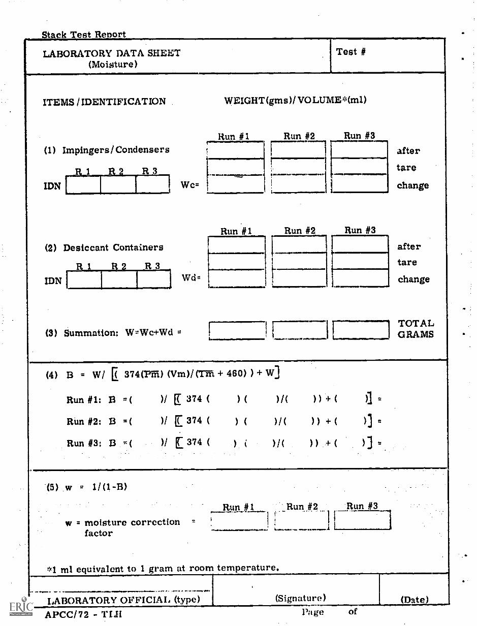
Stack Test Report
LABORATORY DATA SHEET(Moisture)
Test #
ITEMS / IDENTIFICATION WEIGHT(gms)/VOLUME*(m1)
Run #1 Run #2 Run #3(1) Impingers/Condensers ,
R 3
aftertare
change
I
IDN Wc= I
Run #1 Run #2 Run #3
(2) Desiccant Containers
R 1 R2 R3i after
tare
IDN j Wd= change
(3) Summation: W=Wc+Wd = f
...... TOTALGRAMS
(4) 13 = W/ E 374(1''m) (Vm)/(Tffi+ 460) ) + W]
Run #1: 13 .c( )/ [ 374 ( ) ( )/( )) + ( )3 =
Run #2: 13 ,-,( )/ E 374 ( ) ( )/( )) + ( )3 =
Run #3: 13 r- ( ) / ( 374 ( )/( ) ) + ( ) ]
(5) w = 1/(1-B)
Run__#1 Run #2 Run #3) f
w = moisture correction = !! :
factor
*1 ml equivalent to 1 gram at room temperature.
(Signature) (Date)LABORATORY OFFICIAL (type)
APCC/72 TLFI Page of

tack Test Report
LABORATORY DATA SHEET(Orsat)
Test #
Run #1Date% By Volume, (Dry Basis)
Run #2Date% By Volume, (Dry Basis)
Run #3Date% 13y Volume, (Dry Basis)
N CO N9 Time CO Nom,. .... .
ft.*, .ea .,....
4
....
-
_ ........
.
..,....... .
. ... .... .. . . .
. 0.
".. . ......
. s . . .
.
. .
..... ....-. ., .-..
............,...
.
a.....q....
. .
.. .
---
...6
.,.A-.$.04 ,4,................woo.. .......
8
9.....-.
10 Ave Ave, ..# A
Ave .
11 Comp Comp Comp
% b
w = =-----1(13)
volume (Wet Basis) B)
w w 2(13)
% by volume(Wet 13asis)(13)(13)
% by volume (Wet Basis)Min 0 CO N9 H 0 COQ CO ' N9 H 0 CO9 0 CO H 0
14
15 44 28---1.,...
28 : 18i
44 32 I 28 28 18 44 32 28 28 18
OEMMO L
- Mg [ .....____-= ..., Mg7iwr =r = Mg
18 livig/29., 1-= Gd = Gd Gd......--
=EA. 1._______ j -SEAai i i. EA
.-WHERE EA''' (%02) ( %CO/ 2)E0.264 ( %N2) (04,02)-1- (%C0/2)
*Not applicable when producer gas, blast furnace gas, or other fuels high in N2 areused. See Part IV, Sub-Section 5.04
(Signature) (Date)LABORATORY OFFICIAL (TypsiAPCC/72 TOA Page of

Snm
ple
Num
ber
Fuel
Sam
plin
g R
ata
Gro
ss*"
lucr
e-L
abor
a -
tory
Sam
ple
men
tsSa
mpl
elb
s(N
o. )
lbs
Typ
eFu
el
Fuel
Qua
lity
Dat
aV
olat
ileB
tuM
oist
ure
Ash
Mat
ter
Con
tent
as r
ecei
ved
as r
ecei
ved
(d. a
. f. )
as r
ecei
ved
0 b
Wt
0 b
Wt
b W
tB
tu/lb
.Fri
oP;-
Surf
ace
Moi
stur
elo
st (
%)
0 c. *3 la) a
oa 0
'-3 CDU)
TE
ST S
UPE
RV
ISO
R (
type
)
(Si_
atu
re)
LA
BO
RA
TO
RY
OFF
ICIA
L(t
ype)
(Sig
natu
re)
Not
e su
rfac
e m
oist
ure
lost
dur
ing
redu
ctio
n of
gro
ssco
al,sa
mpl
e to
labo
rato
ry s
ampl
e in
per
cent
(as
cr
appl
icam
e.(D
ate)
0 rt

Stack Test Report TestHEAT INPUT DATA
(Fuel UseSHEET
Basis)- III Run #
Number and'T e* Unit Fuel
AshPf
Fuel FiredPi
(pounds)
lIpatinglValue(11Vi)(Btu /lb)
HeatInput (FIT)106 Btu/hr
SampleNo. ***
.
a
,
1, as fired= ashfractions 2, HI =
60Hvi)Totals** e x
a ANNE am r ArP21022 WIFAII Par AIr Ar
* Type a, b, c; see definitions. List all fuels fired underbefore listing the next unit.
** List the total heat input for each type unit separately. If311 were used in combination to determine the Heat Inputsof prorating the heat input between the different type units(Use additional sheet as necessary.)
*** As listed on Porn-) TM.', Laboratory Data Sheet (I.uels).
each unit designation.
Method 111, 211, orexplain the methodas applicable.
e . min.
(Signature)
....._....,
(Date)PROCESS ()13S ER %MU (typo)
APCC/72-T111-11 (1/I) Page of

Stack Test Report Test #HEAT INPUT DATA SHEET - 211
(Steam Balance Basis) Run #
Heat Input for all fuels fired in this unitduring the test run period: 106 Btu/hr
BE:Type Fuel Burning Unit
a
Unit Designation:
Schematic Flow Diagram and Computations:
Note: Use additional blank sheets as necessary. Record the Heat Input for thisunit in the appropriate column of Form THI-II (lii).
APC /72 THI -II (2H) Page

Stack Test Report
HEAT INPUT DATA snimr - 211(Steam 13alanee 13:Isis)
"est #
Run if
Continuation:
APCC/72 - TIII II (210/2 Pa ge of

ack Test Report Test
HEAT INPUT DATA SHEET - 3H.(flue gas analysis basis)
Run #
1.As Qo Co Gd
( ) ( ) ( ) ( - Wh (AFG =)
An
Wh = Ws + Wa; See Part V, Sub-Section 8.04 Particulate Matter Stack EmissionCompliance Test Procedure TI' -2 use additional sheets as necessary.
AFG v. lbs. (1 + EA) . L. 1
2. Fuels Fired Cf HVf/10,000lbs - air
THA lbs - fuel44,4
...........
......
:=411
...:
r-f 1..0. . .. .. ..A .. A .. rmr mn ..r ..---
'===.111/1Ml= --A
3. Fuels Fired Wf AFG f
gc::: .....-.--:::77::::......._..........T.,..........:c --... . . . . . ......---
4,-,
_ .. .4:
.---.......:,C
* metered fuels** fuel (cf ) AFG0 =not metered
AFG AFG04,
Warm ( ) - ( )
( ) - ( )Xey P'
Wci = lbsil E.) = n.in.
APCC/7 2-1111I-11 (310 Page of
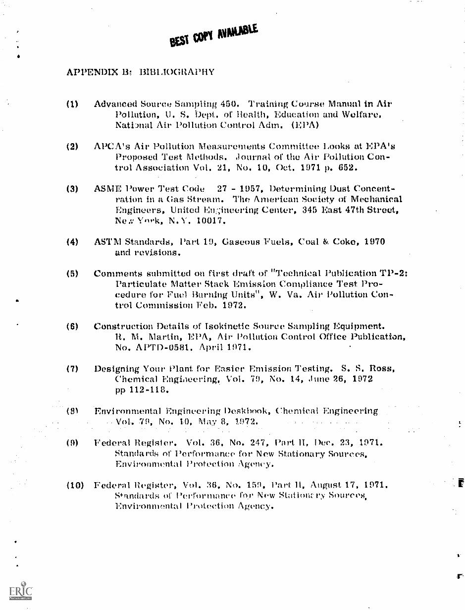
SESI COPI MIPOWE
APPENDIX 13: 13IBLI0GRAPHY
(1) Advanced Source Sampling 450. Training Course Manual in AirPollution, U. S. Dept. of Health, Education and Welfare.National Air Pollution Control Adm. (EPA)
(2) APC A's Air Pollution Measurements Committee Looks at EPA'sProposed Test Methods. Journal. of the Air Pollution Con-trol Association Vol. 21, No. 10, Oct. 1971 p. 652.
(3) ASME Power Test Code 27 - 1957, Determining Dust Concent-ration in a Gas Stream. The American Society of MechanicalEngineers, United En:;ineering Center, 345 East 47th Street,Ne York, N. Y. 10017.
(4) ASTM Standards, Part 19, Gaseous Fuels, Coal & Coke, 1970and revisions.
(5) Comments submitted on first draft of "Technical Publication TP-2:Particulate Matter Stack Emission Compliance Test Pro-cedure for Furl Burning Units'', W. Va. Air Pollution Con-trol Commission Feb. 1972.
(6) Construction Details of Isokinetic Source Sampling Equipment.It. M. Martin, EPA, Air Pollution Control Office Publication,No. APTI)- 0581. April 1971.
(7) Designing Your Plant for Easier Emission Testing. S. S. floss,Chemical Engineering, Vol. 79, No. 14, June 26, 1972pp 112-118.
(81 Environmental Engineering Deskbook, Chemical_EngineeringVol. 79, No. 10, May 8, 1972.
(9) Federal Register. Vol. 36, No. 247, Part 11, Dec. 23, 1971.Standards of Performance for New Stationary Sources,Environmental Protection Agency.
(10) Federal Register, Vol. 36, No. 159, Part 11, August 17, 1971.S*a.ndards of Performance for New Stationz-ry Sources,Envionnvmtal Protection Agency.

BEST COPY AVAILABLE
(1,1) handbook of Air Pollution. 3. P. Sheehy, W. C. Aehingor, It.A. Simon. Air Pollution Training Program. 11. S. Dept.of Health, Education and kVe Rare, Robert A. Taft SanitaryEngineering Center.
(12) Maintenance, :al ibration and Operation u1 lsokinetie SourceSampling Equipment. J. 3. I7: PA, Mardi 1972,orrice of Air Programs, No. Al"1D-0576.
(13) Methods For Determination of Velocity, Volume, Dust and MistContent of Gases. Rulletin WI' -130. Western PrecipitationDivision of .1oN Manufacturing Company, 1068.
(14) Regulation 11 - Prevent and Corol Particulate Air Pollutionfrom ComhuFltiri of Fuel in Indirect Heat Exchangers.Chapter 16-20, Series 1.1 (1972). West Virginia AdministrationRegulation, Air Pollution Control Commission.
(15) Source Testing, of Utility Boilers for Pr.:rticulate awl GaseousEmissions, 10. A. Govan 6., A. Teraciano of YorkResearch Corporation and Jerome Ruin at' EPA. AirPollution Control Association, 65th annual meeting,Miami Beach, Florida, June 18-22, 1972.
(16) Source Testing for Air Pollution Control, l t, li. U. Cooper,and A. T. Rossano, .1 r. , linlversity of Washington, Dept.of Civil Engineering Environmental Science Service Division,Environmental Research K Applications, Inc.
(17) Stack Dust Sampling: in-stack filler or E. P. A. train, W. C,Ilemeon and A. W. Black of Associates, Journalof the Air Pollution Control Association Vol. 22, No. 7,July 172, m) 516-518.
(18) Steam, Its Generation Use. The Babcock It. Wilcox Company,N. Y., 37th edition,. 1960. George Mckilthin & Son,. N. V.