tlv320adc3001 low-power stereo adc with … · i2s, lj, rj, dsp, tdm processor tlv320adc3001 adc...
TRANSCRIPT

I2S, LJ, RJ, DSP, TDM
Processor
TLV320ADC3001
ADC
miniDSPADC
I2C
Product
Folder
Sample &Buy
Technical
Documents
Tools &
Software
Support &Community
TLV320ADC3001SLAS548D –OCTOBER 2008–REVISED SEPTEMBER 2015
TLV320ADC3001 Low-Power Stereo ADC With Embedded miniDSPfor Wireless Handsets and Portable Audio
1
1 Features• Stereo Audio ADC • 2.24-mm × 2.16-mm NanoFree™ 16-Ball 16-YZH
Wafer Chip Scale Package (WCSP)– 92-dBA Signal-to-Noise Ratio– Supports ADC Sample Rates From 8 kHz to 2 Applications96 kHz
• Wireless Handsets• Instruction-Programmable Embedded miniDSP• Portable Low-Power Audio Systems• Flexible Digital Filtering With RAM Programmable• Noise Cancellation SystemsCoefficient, Instructions, and Built-In Standard
Modes • Front-End Voice or Audio Processor for DigitalAudio– Low-Latency IIR Filters for Voice
– Linear Phase FIR Filters for Audio3 Description– Additional Programmable IIR Filters for EQ,The TLV320ADC3001 device is a low-power, stereoNoise Cancellation, or Reduction audio analog-to-digital converter (ADC) supporting
– Up to 128 Programmable ADC Digital Filter sampling rates from 8 kHz to 96 kHz with anCoefficients integrated programmable-gain amplifier providing up
to 40-dB analog gain or AGC. A programmable• Three Audio Inputs With Configurable AutomaticminiDSP is provided for custom audio processing.Gain Control (AGC)Front-end input coarse attenuation of 0 dB, –6 dB, or– Programmable in Single-Ended or Fully off, is also provided. The inputs are programmable inDifferential Configurations a combination of single-ended or fully differential
– Can Be Driven Hi-Z for Easy Interoperability configurations. Extensive register-based powerWith Other Audio ICs control is available via I2C, enabling mono or stereo
recording. Low power consumption makes the• Low Power Consumption and Extensive ModularTLV320ADC3001 ideal for battery-powered portablePower Control:equipment.
– 6-mW Mono Record 8-kHzDevice Information(1)– 11-mW Stereo Record, 8-kHz
PART NUMBER PACKAGE BODY SIZE (NOM)– 10-mW Mono Record, 48-kHzTLV320ADC3001 DSBGA (16) 2.24 mm × 2.16 mm– 17-mW Stereo Record, 48-kHz(1) For all available packages, see the orderable addendum at• Programmable Microphone Bias
the end of the data sheet.• Programmable PLL for Clock Generation• I2C Control Bus Functional Block Diagram• Audio Serial Data Bus Supports I2S, Left/Right-
Justified, DSP, PCM, and TDM Modes• Power Supplies:
– Analog: 2.6 V–3.6 V.– Digital: Core: 1.65 V–1.95 V,
I/O: 1.1 V–3.6 V
1
An IMPORTANT NOTICE at the end of this data sheet addresses availability, warranty, changes, use in safety-critical applications,intellectual property matters and other important disclaimers. PRODUCTION DATA.

TLV320ADC3001SLAS548D –OCTOBER 2008–REVISED SEPTEMBER 2015 www.ti.com
Table of Contents1 Features .................................................................. 1 10 Detailed Description ........................................... 13
10.1 Overview ............................................................... 132 Applications ........................................................... 110.2 Functional Block Diagram ..................................... 133 Description ............................................................. 110.3 Feature Description............................................... 144 Revision History..................................................... 210.4 Device Functional Modes...................................... 405 Description (continued)......................................... 410.5 Programming......................................................... 406 Device Comparison Table ..................................... 410.6 Register Maps ....................................................... 427 Pin Configuration and Functions ......................... 5 11 Application and Implementation........................ 748 Specifications......................................................... 6 11.1 Application Information.......................................... 74
8.1 Absolute Maximum Ratings ...................................... 6 11.2 Typical Application ............................................... 748.2 ESD Ratings.............................................................. 6 12 Power Supply Recommendations ..................... 788.3 Recommended Operating Conditions....................... 6
13 Layout................................................................... 798.4 Thermal Information .................................................. 613.1 Layout Guidelines ................................................. 798.5 Electrical Characteristics........................................... 713.2 Layout Example .................................................... 798.6 Dissipation Ratings .................................................. 8
14 Device and Documentation Support ................. 808.7 I2S/LJF/RJF Timing in Master Mode......................... 814.1 Community Resources.......................................... 808.8 DSP Timing in Master Mode..................................... 814.2 Trademarks ........................................................... 808.9 I2S/LJF/RJF Timing in Slave Mode........................... 914.3 Electrostatic Discharge Caution............................ 808.10 DSP Timing in Slave Mode..................................... 914.4 Glossary ................................................................ 808.11 Typical Characteristics .......................................... 12
15 Mechanical, Packaging, and Orderable9 Parameter Measurement Information ................ 12Information ........................................................... 80
4 Revision HistoryNOTE: Page numbers for previous revisions may differ from page numbers in the current version.
Changes from Revision C (April 2011) to Revision D Page
• Added Pin Configuration and Functions section, ESD Ratings table, Feature Description section, Device FunctionalModes, Application and Implementation section, Power Supply Recommendations section, Layout section, Deviceand Documentation Support section, and Mechanical, Packaging, and Orderable Information section .............................. 1
Changes from Revision B (March 2010) to Revision C Page
• Changed pinout diagram to top view...................................................................................................................................... 5• Inserted missing table reference .......................................................................................................................................... 75
Changes from Revision A (November, 2008) to Revision B Page
• Added miniDSP to data-sheet title.......................................................................................................................................... 1• Added miniDSP bullet to the Features list.............................................................................................................................. 1• Added a sentence about the miniDSP to the Description section.......................................................................................... 1• Deleted YZH and WCSP options from the SIMPLIFIED BLOCK DIAGRAM. ........................................................................ 4• Alphabetized Pin Functions table ........................................................................................................................................... 5• Changed "complacence" to "compliance" in Note 2 of the Abs Max table............................................................................. 6• Changed θJA to RθJA ............................................................................................................................................................... 6• Added AVDD = 3.3 V to Electrical Characteristics condition statement................................................................................. 7• Added input common-mode voltage row to Electrical Characteristics table .......................................................................... 7• Added integrated noise row to Electrical Characteristics ....................................................................................................... 8• Added AVDD = 3.3 V to Electrical Characteristics condition statement................................................................................. 8• Added metric dimensions to Note 1 of the DISSIPATIONS RATINGS table ......................................................................... 8• Added rise and fall times to the waveform, Figure 1 ............................................................................................................ 10
2 Submit Documentation Feedback Copyright © 2008–2015, Texas Instruments Incorporated
Product Folder Links: TLV320ADC3001

TLV320ADC3001www.ti.com SLAS548D –OCTOBER 2008–REVISED SEPTEMBER 2015
• Added rise and fall times to waveform, Figure 2 .................................................................................................................. 10• Added rise and fall times to waveform, Figure 3 .................................................................................................................. 10• Changed signs of nonzero errors in % ERROR column ...................................................................................................... 24
Changes from Original (September 2008) to Revision A Page
• Changed Figure 4 - DSP Timing in Slave Mode. Added the WCLK text note. .................................................................... 11• Removed note following the page 0 / register 94 description table ..................................................................................... 58• Changed bit values from 1 and 2 to 0 and 1, respectively. .................................................................................................. 58• Listed values 81 through 127 as reserved ........................................................................................................................... 58• Replaced the listing of page-4 registers ............................................................................................................................... 64• Added a listing for page-5 registers...................................................................................................................................... 69• Changed Figure 44 Typical Connections ............................................................................................................................. 74
Copyright © 2008–2015, Texas Instruments Incorporated Submit Documentation Feedback 3
Product Folder Links: TLV320ADC3001

TLV320ADC3001SLAS548D –OCTOBER 2008–REVISED SEPTEMBER 2015 www.ti.com
5 Description (continued)The AGC programs to a wide range of attack (7 ms–1.4 s) and decay (50 ms–22.4 s) times. A programmablenoise gate function is included to avoid noise pumping. Low-latency IIR filters optimized for voice and telephonyare available, as well as linear-phase FIR filters optimized for audio. Programmable IIR filters are also availableand may be used for sound equalization, or to remove noise components. The audio serial bus can beprogrammed to support I2S, left-justified, right-justified, DSP, PCM, and TDM modes. The audio bus may beoperated in either master or slave mode.
A programmable integrated PLL is included for flexible clock generation and support for all standard audio ratesfrom a wide range of available MCLKs, varying from 512 kHz to 50 MHz, including the most popular cases of 12-MHz, 13-MHz, 16-MHz, 19.2-MHz, and 19.68-MHz system clocks.
6 Device Comparison Table
FEATURES TLV320ADC3001 TLV320ADC3101Number of ADCs 2 2Number of Inputs / Outputs 3 / Digital I/F 6 / Digital I/FResolution (Bits) 24 24Control Interface I2C I2CDigital Audio Interface LJ, RJ, I2S, DSP, TDM LJ, RJ, I2S, DSP, TDMDigital Microphone Support No Yes
4 Submit Documentation Feedback Copyright © 2008–2015, Texas Instruments Incorporated
Product Folder Links: TLV320ADC3001

A1
A3
A2
A4
B1
B3
B2
B4
C1
C3
C2
C4
D1
D3
D2
D4
TLV320ADC3001www.ti.com SLAS548D –OCTOBER 2008–REVISED SEPTEMBER 2015
7 Pin Configuration and Functions
YZH Package16-Pin DSBGA
Top View
Pin FunctionsPIN
TYPE DESCRIPTIONNO. NAME
A1 MICBIAS O Microphone output bias voltage
A2 RESET I Reset
A3 SCL I/O I2C serial clock
A4 SDA I/O I2C serial data input/output
B1 IN1R(M) I Analog input – first right single-ended or differential minus input
B2 AVDD P Analog voltage supply, 2.6 V–3.6 V
B3 DVDD P Digital core voltage supply, 1.65 V–1.95 V
B4 IOVDD P I/O voltage supply, 1.1 V–3.6 V
C1 IN1L(P) I Analog input – first left single-ended or differential plus input
C2 AVSS P Analog ground supply, 0 V
C3 DVSS P Digital ground supply, 0 V
C4 MCLK I Master clock input
D1 IN2L I Analog input – second left single-ended
D2 DOUT O Audio serial data bus data output (output)
D3 WCLK I/O Audio serial data bus word clock (input/output)
D4 BCLK I/O Audio serial data bus bit clock (input/output)
Copyright © 2008–2015, Texas Instruments Incorporated Submit Documentation Feedback 5
Product Folder Links: TLV320ADC3001

TLV320ADC3001SLAS548D –OCTOBER 2008–REVISED SEPTEMBER 2015 www.ti.com
8 Specifications
8.1 Absolute Maximum Ratingsover operating free-air temperature range (unless otherwise noted) (1)
MIN MAX UNITAVDD to AVSS –0.3 3.9 VIOVDD to DVSS –0.3 3.9 VDVDD to DVSS –0.3 2.5 VDigital input voltage to DVSS –0.3 IOVDD + V
0.3Analog input voltage to AVSS –0.3 AVDD + 0.3 VOperating temperature –40 85 °C
TJ Max Junction temperature 105 °CPower dissipation (TJ Max – TA) / θJA W
Tstg Storage temperature –65 125 °C
(1) Stresses beyond those listed under Absolute Maximum Ratings may cause permanent damage to the device. These are stress ratingsonly, and functional operation of the device at these or any other conditions beyond those indicated under Recommended OperatingConditions is not implied. Exposure to absolute-maximum-rated conditions for extended periods may affect device reliability.
8.2 ESD RatingsVALUE UNIT
Human body model (HBM), per ANSI/ESDA/JEDEC JS-001 (1) ±2500V(ESD) Electrostatic discharge VCharged-device model (CDM), per JEDEC specification JESD22- ±1000
C101 (2)
(1) JEDEC document JEP155 states that 500-V HBM allows safe manufacturing with a standard ESD control process.(2) JEDEC document JEP157 states that 250-V CDM allows safe manufacturing with a standard ESD control process.
8.3 Recommended Operating Conditionsover operating free-air temperature range (unless otherwise noted)
MIN NOM MAX UNITAVDD (1) Analog supply voltage 2.6 3.3 3.6 VDVDD (1) Digital core supply voltage 1.65 1.8 1.95 VIOVDD (1) Digital I/O supply voltage 1.1 1.8 3.6 VVI Analog full-scale 0-dB input voltage (AVDD = 3.3 V) 0.707 Vrms
Digital output load capacitance 10 pFTA Operating free-air temperature –40 85 °C
(1) Analog voltage values are with respect to AVSS; digital voltage values are with respect to DVSS.
8.4 Thermal InformationTLV320ADC3001
THERMAL METRIC (1) YZH (DSBGA) UNIT16 PINS
RθJA Junction-to-ambient thermal resistance 70.9 °C/WRθJC(top) Junction-to-case (top) thermal resistance 0.3 °C/WRθJB Junction-to-board thermal resistance 13.7 °C/WψJT Junction-to-top characterization parameter 1.7 °C/WψJB Junction-to-board characterization parameter 13.7 °C/WRθJC(bot) Junction-to-case (bottom) thermal resistance — °C/W
(1) For more information about traditional and new thermal metrics, see the Semiconductor and IC Package Thermal Metrics applicationreport, SPRA953.
6 Submit Documentation Feedback Copyright © 2008–2015, Texas Instruments Incorporated
Product Folder Links: TLV320ADC3001

TLV320ADC3001www.ti.com SLAS548D –OCTOBER 2008–REVISED SEPTEMBER 2015
8.5 Electrical CharacteristicsAt 25°C, AVDD = 3.3 V, IOVDD = 1.8 V, DVDD = 1.8 V, fS = 48-kHz, 16-bit audio data (unless otherwise noted)
PARAMETER TEST CONDITIONS MIN TYP MAX UNITAUDIO ADC
Input signal level (0-dB) Single-ended input 0.707 VrmsInput common-mode voltage Single-ended input 1.35 VrmsSignal-to-noise ratio, fS = 48 kHz, 0-dB PGA gain, IN1 inputs selected 80 92 dBA-weighted (1) (2) and AC-shorted to groundDynamic range, fS = 48 kHz, 1-kHz –60-dB full-scale input 92 dBA-weighted (1) (2) applied at IN1 inputs, 0-dB PGA gain
fS = 48 kHz, 1-kHz –2-dB full-scale input applied –90 –75 dBat IN1THD Total harmonic distortion
0.003% 0.017%inputs, 0-dB PGA gain234 Hz, 100 mVPP on AVDD, single-ended input 46
Power-supply rejection ratio dB234 Hz, 100 mVPP on AVDD, differential input 68
ADC channel separation 1 kHz, –2 dB IN1L to IN1R –73 dBADC gain error 1-kHz input, 0-dB PGA gain 0.7 dBADC programmable-gain amplifier 1-kHz input tone, RSOURCE < 50 Ω 40 dBmaximum gainADC programmable-gain amplifier 0.502 dBstep size
IN1 inputs, routed to single ADC 35Input mix attenuation = 0 dBIN2 inputs, input mix attenuation = 0 dB 35Input resistance kΩIN1 inputs, input mix attenuation = –6 dB 62.5IN2 inputs, input mix attenuation = –6 dB 62.5
Input capacitance 10 pFInput level control minimum 0 dBattenuation settingInput level control maximum 6 dBattenuation settingInput level control attenuation step 6 dBsize
ADC DIGITAL DECIMATION FILTER fS = 48 kHzFilter gain from 0 to 0.39 fS Filter A, AOSR = 128 or 64 ±0.1 dBFilter gain from 0.55 fS to 64 fS Filter A, AOSR = 128 or 64 –73 dBFilter group delay Filter A, AOSR = 128 or 64 17/fS sFilter gain from 0 to 0.39 fS Filter B, AOSR = 64 ±0.1 dBFilter gain from 0.60 fS to 32 fS Filter B, AOSR = 64 -46 dBFilter group delay Filter B, AOSR = 64 11/fS sFilter gain from 0 to 0.39 fS Filter C, AOSR = 32 ±0.033 dBFilter gain from 0.28 fS to 16 fS Filter C, AOSR = 32 -60 dBFilter group delay Filter C, AOSR = 32 11/fS s
MICROPHONE BIAS2
2.25 2.5 2.75Bias voltage Programmable settings, load = 750 Ω VAVDD– 0.2
Current sourcing 2.5 V setting 4 mA
(1) Ratio of output level with 1-kHz full-scale sine-wave input, to the output level with the inputs short-circuited, measured A-weighted over a20-Hz to 20-kHz bandwidth using an audio analyzer.
(2) All performance measurements done with 20-kHz lowpass filter and, where noted, A-weighted filter. Failure to use such a filter mayresult in higher THD+N and lower SNR and dynamic range readings than shown in the Electrical Characteristics. The lowpass filterremoves out-of-band noise, which, although not audible, may affect dynamic specification values.
Copyright © 2008–2015, Texas Instruments Incorporated Submit Documentation Feedback 7
Product Folder Links: TLV320ADC3001

TLV320ADC3001SLAS548D –OCTOBER 2008–REVISED SEPTEMBER 2015 www.ti.com
Electrical Characteristics (continued)At 25°C, AVDD = 3.3 V, IOVDD = 1.8 V, DVDD = 1.8 V, fS = 48-kHz, 16-bit audio data (unless otherwise noted)
PARAMETER TEST CONDITIONS MIN TYP MAX UNITBW = 20 Hz to 20 kHz, A-weighted, 1-µF µVrIntegrated noise 3.3capacitor between MICBIAS and AGND ms
DIGITAL I/O0.3 ×VIL Input low level IIL = 5 μA –0.3 VIOVDD
0.7 ×VIH Input high level (3) IIH = 5 μA VIOVDD0.1 ×VOL Output low level IIH = 2 TTL loads VIOVDD
0.8 ×VOH Output high level IOH = 2 TTL loads VIOVDDSUPPLY CURRENT fS = 48 kHz, AVDD = 3.3 V, DVDD = IOVDD = 1.8 V
AVDD 2Mono record PLL and AGC off mA
DVDD 1.9AVDD 4
Stereo record PLL and AGC off mADVDD 2.1AVDD 1.1Additional power consumed whenPLL mAPLL is poweredDVDD 0.8AVDD 0.04All supply voltages applied, all blocksPower down μAprogrammed in lowest power stateDVDD 0.7
(3) When IOVDD < 1.6 V, minimum VIH is 1.1 V.
8.6 Dissipation Ratings (1)
TA = 25°C TA = 75°C TA = 85°CPACKAGE TYPE DERATING FACTORPOWER RATING POWER RATING POWER RATINGDSBGA 1052.6 mW 13.1 mW/°C 394.7 mW 263.2 mW
(1) This data was taken using 2 oz. (0.071-mm thick) trace and copper pad that is soldered directly to a JEDEC standard 4-layer 3-in. × 3-in. (7.62-cm × 7.62-cm) PCB.
8.7 I2S/LJF/RJF Timing in Master ModeSpecified at 25°C, DVDD = 1.8 V. All timing specifications are measured at characterization. See Figure 1 for timing diagram.
IOVDD = 1.8 V IOVDD = 3.3 VUNIT
MIN MAX MIN MAXtd(WS) BCLK/WCLK delay time 20 15 nstd(DO-WS) BCLK/WCLK to DOUT delay time 25 20 nstd(DO-BCLK) BCLK to DOUT delay time 20 15 nstr Rise time 20 15 nstf Fall time 20 15 ns
8.8 DSP Timing in Master ModeSpecified at 25°C, DVDD = 1.8 V. All timing specifications are measured at characterization. See Figure 2 for timing diagram.
IOVDD = 1.8 V IOVDD = 3.3 VUNIT
MIN MAX MIN MAXtd(WS) BCLK/WCLK delay time 25 15 nstd(DO-BCLK) BCLK to DOUT delay time 25 15 nstr Rise time 20 15 nstf Fall time 20 15 ns
8 Submit Documentation Feedback Copyright © 2008–2015, Texas Instruments Incorporated
Product Folder Links: TLV320ADC3001

TLV320ADC3001www.ti.com SLAS548D –OCTOBER 2008–REVISED SEPTEMBER 2015
8.9 I2S/LJF/RJF Timing in Slave ModeSpecified at 25°C, DVDD = 1.8 V. All timing specifications are measured at characterization. See Figure 3 for timing diagram.
IOVDD = 1.8 V IOVDD = 3.3 VUNIT
MIN MAX MIN MAXtH(BCLK) BCLK high period 35 35 nstL(BCLK) BCLK low period 35 35 nsts(WS) BCLK/WCLK setup time 10 6 nsth(WS) BCLK/WCLK hold time 10 6 ns
BCLK/WCLK to DOUT delay time (fortd(DO-WS) 30 30 nsLJF Mode only)td(DO-BCLK) BCLK to DOUT delay time 25 20 nstr Rise time 16 8 nstf Fall time 16 8 ns
8.10 DSP Timing in Slave ModeSpecified at 25°C, DVDD = 1.8 V. All timing specifications are measured at characterization. See Figure 4 for timing diagram.
IOVDD = 1.8 V IOVDD = 3.3 VUNIT
MIN MAX MIN MAXtH(BCLK) BCLK high period 35 35 nstL(BCLK) BCLK low period 35 35 nsts(WS) BCLK/WCLK setup time 10 8 nsth(WS) BCLK/WCLK hold time 10 8 nstd(DO-BCLK) BCLK to DOUT delay time 25 20 nstr Rise time 15 8 nstf Fall time 15 8 ns
Copyright © 2008–2015, Texas Instruments Incorporated Submit Documentation Feedback 9
Product Folder Links: TLV320ADC3001

WCLK
BCLK
DOUT
t (WS)h
t (BCLK)H
t (DO-BCLK)d
t (DO-WS)dt (BCLK)L
t (WS)S
tr tf
WCLK
BCLK
DOUT
t (DO-BCLK)d
t (WS)d t (WS)d
tf tr
WCLK
BCLK
DOUT
t (DO-BCLK)dt (DO-WS)d
t (WS)d
tr tf
TLV320ADC3001SLAS548D –OCTOBER 2008–REVISED SEPTEMBER 2015 www.ti.com
Figure 1. I2S/LJF/RJF Timing in Master Mode
Figure 2. DSP Timing in Master Mode
Figure 3. I2S/LJF/RJF Timing in Slave Mode
10 Submit Documentation Feedback Copyright © 2008–2015, Texas Instruments Incorporated
Product Folder Links: TLV320ADC3001

WCLK
BCLK
DOUT
t (BCLK)H
t (WS)h
t (BCLK)L
t (WS)st (WS)h
t (DO-BCLK)d
t (WS)h
tf tr
(see NOTE)
TLV320ADC3001www.ti.com SLAS548D –OCTOBER 2008–REVISED SEPTEMBER 2015
Note A. Falling edge inside a frame for WCLK is arbitrary inside frame.
Figure 4. DSP Timing in Slave Mode
Copyright © 2008–2015, Texas Instruments Incorporated Submit Documentation Feedback 11
Product Folder Links: TLV320ADC3001

5
7
9
11
13
15
17
0 5 10 15 20 25 30 35 40
PGA Gain Setting - dB
Left Channel
Right Channel
Inp
ut-
Refe
rred
No
ise -
Vm
RM
S
-140
-120
-100
-80
-60
-40
-20
0
0 1 2 3 4 5 6 7 8 9 10 11 12 13 14 15 16 17 18 19 20
Frequency - kHz
dB
MICBIAS=2.0V
MICBIAS=2.5V
MICBIAS=AVDD
1.8
2
2.2
2.4
2.6
2.8
3
3.2
-45 -35 -25 -15 -5 5 15 25 35 45 55 65 75 85
Temp - C
Mic
bia
s -
V
1.8
1.9
2
2.1
2.2
2.3
2.4
2.5
2.6
2.7
2.8
2.9
3
3.1
3.2
3.3
3.4
3.5
2.7 2.8 2.9 3 3.1 3.2 3.3 3.4 3.5 3.6
AVDD - V
Mic
bia
s -
V
MICBIAS = AVDD
MICBIAS = 2.5 V
MICBIAS = 2 V
Gain
- d
B
PGA Gain Setting - dB
0
0.05
0.10
0.15
0.20
0.25
0.30
0.35
0.40
0.45
0 10 20 30 40
Left Gain Error
Right Gain Error
TLV320ADC3001SLAS548D –OCTOBER 2008–REVISED SEPTEMBER 2015 www.ti.com
8.11 Typical Characteristics
Figure 5. Single-Ended Gain Error Figure 6. MICBIAS Output Voltage vs AVDD
Figure 7. MICBIAS Output Voltage vs Ambient Temperature Figure 8. Line Input to ADC FFT Plot
Figure 9. Input-Referred Noise vs PGA Gain
9 Parameter Measurement Information
All parameters are measured according to the conditions described in the Specifications section.
12 Submit Documentation Feedback Copyright © 2008–2015, Texas Instruments Incorporated
Product Folder Links: TLV320ADC3001

PGA0 dB to 40 dB0.5-dB steps
ADC
AGC
DV
DD
DV
SS
IOV
DD
AV
DD
AV
SS
Current Bias/Reference
Audio ClockGeneration
PLL
MC
LK
I2C Serial
Control Bus
SC
L
SD
A
I2STDMSerialBus
Interface
DOUT
BCLK
WCLK
TLV320ADC3001
IN1L(P)
All stages: 0, –6 dB, or Offby Register Setting
IN1R(M)
AnalogSignalInput
Switching
MIC
BIA
S
MicBias
IN2L
ADC
AGC
miniDSPProcessing
Blocks
RE
SE
T
PGA0 dB to 40 dB0.5-dB steps
TLV320ADC3001www.ti.com SLAS548D –OCTOBER 2008–REVISED SEPTEMBER 2015
10 Detailed Description
10.1 OverviewThe TLV320ADC3001 is a flexible, low-power, stereo audio ADC product with extensive feature integration,intended for applications in smartphones, PDAs, and portable computing, communication, and entertainmentapplications. The product integrates a host of features to reduce cost, board space, and power consumption inspace-constrained, battery-powered, portable applications.
The TLV320ADC3001 consists of the following blocks:• Stereo audio multibit delta-sigma ADC (8 kHz–96 kHz)• miniDSP for custom processing• Built-in processing blocks for selectable digital audio effects (3-D, bass, treble, midrange, EQ, de-emphasis)• Register configurable combinations of up to three single-ended or one differential and one single-ended audio
inputs• Fully programmable PLL with extensive ADC clock source and divider options for maximum end-system
design flexibility• 16-ball wafer chip-scale package (DSBGA YZH)
Communication to the TLV320ADC3001 for control is via a two-wire I2C interface. The I2C interface supportsboth standard and fast communication modes.
10.2 Functional Block Diagram
Copyright © 2008–2015, Texas Instruments Incorporated Submit Documentation Feedback 13
Product Folder Links: TLV320ADC3001

TLV320ADC3001SLAS548D –OCTOBER 2008–REVISED SEPTEMBER 2015 www.ti.com
10.3 Feature Description
10.3.1 Hardware ResetThe TLV320ADC3001 requires a hardware reset after power up for proper operation. After all power supplies areat their specified values, the RESET pin must be driven low for at least 10 ns. If this reset sequence is notperformed, the TLV320ADC3001 may not respond properly to register reads/writes.
10.3.2 PLL Start-upWhen the PLL is powered on, a start-up delay of approximately 10 ms occurs after the power-up command of thePLL and before the clocks are available to the TLV320ADC3001. This delay is to ensure stable operation of thePLL and clock-divider logic.
10.3.3 Software Power DownBy default, all circuit blocks are powered down following a reset condition. Hardware power up of each circuitblock can be controlled by writing to the appropriate control register. This approach allows the lowest power-supply current for the functionality required. However, when a block is powered down, all of the register settingsare maintained as long as power is still being applied to the device.
10.3.4 miniDSPThe TLV320ADC3001 features a miniDSP core which is tightly coupled to the ADC. The fully programmablealgorithms for the miniDSP must be loaded into the device after power up. The miniDSP has direct access to thedigital stereo audio stream, offering the possibility for advanced, very low-group-delay DSP algorithms. The ADCminiDSP has 512 programmable instructions, 256 data memory locations, and 128 programmable coefficients.
Software development for the TLV320ADC3001 is supported through TI's comprehensive PurePath™ Studiosoftware development environment, a powerful, easy-to-use tool designed specifically to simplify softwaredevelopment on Texas Instruments miniDSP audio platforms. The graphical development environment consistsof a library of common audio functions that can be dragged and dropped into an audio signal flow and graphicallyconnected together. The DSP code can then be assembled from the graphical signal flow with the click of amouse. See the TLV320ADC3001 product folder on www.ti.com to learn more about PurePath Studio softwareand the latest status on available, ready-to-use DSP algorithms.
10.3.5 Audio Data ConvertersThe TLV320ADC3001 supports the following standard audio sampling rates: 8 kHz, 11.025 kHz, 12 kHz, 16 kHz,22.05 kHz, 24 kHz, 32 kHz, 44.1 kHz, 48 kHz, 88.2 kHz, and 96 kHz. The converters can also operate atdifferent sampling rates in various combinations, which are described further as follows.
The TLV320ADC3001 supports a wide range of options for generating clocks for the ADC section as well as thedigital interface section and the other control blocks as shown in Figure 27. The clocks for the ADC require asource reference clock. The clock can be provided on device pins MCLK and BCLK. The source reference clockfor the ADC section can be chosen by programming the ADC_CLKIN value on page 0 / register 4, bits D1–D0.The ADC_CLKIN can then be routed through highly flexible clock dividers shown in Figure 27 to generate variousclocks required for the ADC and programmable digital filter sections. In the event that the desired audio orprogrammable digital filter clocks cannot be generated from the external reference clocks on MCLK and BCLK,the TLV320ADC3001 also provides the option of using an on-chip PLL, which supports a wide range of fractionalmultiplication values to generate the required system clocks. Starting from ADC_CLKIN, the TLV320ADC3001provides for several programmable clock dividers to help achieve a variety of sampling rates for the ADC and theclocks for the programmable digital filter section.
10.3.6 Digital Audio Data Serial InterfaceAudio data is transferred between the host processor and the TLV320ADC3001 via the digital-audio serial-datainterface, or audio bus. The audio bus on this device is flexible, including left- or right-justified data options,support for I2S or PCM protocols, programmable data-length options, a TDM mode for multichannel operation,flexible master/slave configurability for each bus clock line, and the ability to communicate with multiple deviceswithin a system directly.
14 Submit Documentation Feedback Copyright © 2008–2015, Texas Instruments Incorporated
Product Folder Links: TLV320ADC3001

3 N
WCLK
BCLK
DOUT N -1 N -2 N - 01 N -2 -3 2 1 0X N -1 X
1/fs
DOUT_Tristate
TLV320ADC3001www.ti.com SLAS548D –OCTOBER 2008–REVISED SEPTEMBER 2015
Feature Description (continued)The audio serial interface on the TLV320ADC3001 has an extensive I/O control to allow for communicating withtwo independent processors for audio data. The processors can communicate with the device one at a time. Thisfeature is enabled by register programming of the various pin selections.
The audio bus of the TLV320ADC3001 can be configured for left- or right-justified, I2S, DSP, or TDM modes ofoperation, where communication with standard telephony PCM interfaces is supported within the TDM mode.These modes are all MSB-first, with data width programmable as 16, 20, 24, or 32 bits by configuring page 0 /register 27, bits D5–D4. In addition, the word clock and bit clock can be independently configured in eithermaster or slave mode for flexible connectivity to a wide variety of processors. The word clock is used to definethe beginning of a frame, and may be programmed as either a pulse or a square-wave signal. The frequency ofthis clock corresponds to the maximum of the selected ADC sampling frequencies.
The bit clock is used to clock in and out the digital audio data across the serial bus. When in master mode, thissignal can be programmed to generate variable clock pulses by controlling the bit-clock divider in page 0 /register 30 (see Figure 27). Accommodating various word lengths as well as supporting the case when multipleTLV320ADC3001s share the same audio bus may require that the number of bit-clock pulses in a frame beadjusted.
The TLV320ADC3001 also includes a feature to offset the position of the start of data a transfer with respect tothe word clock. There are two configurations that allow the user to use either a single offset for both channels orto use separate offsets. Ch_Offset_1 reference represents the value in page 0 / register 28, and Ch_Offset_2represents the value in page 0 / register 37. When page 0 / register 38, bit D0 is set to zero (time-slot-basedchannel assignment is disabled), the offset of both channels is controlled, in terms of number of bit clocks, by theprogramming in page 0 / register 28 (Ch_Offset_1). When page 0 / register 38, bit D0 = 1 (time-slot-basedchannel assignment enabled), the first channel is controlled, in terms of number of bit clocks, by theprogramming in page 0 / register 28 (Ch_Offset_1), and the second channel is controlled, in terms of number ofbit clocks, by the programming in page 0 / register 37 (Ch_Offset_2), where register 37 programs the delaybetween the first word and the second word. Also, the relative order of the two channels can be swapped,depending on the programmable register bit (page 0 / register 38, bit D4) that enables swapping of the channels.
The TLV320ADC3001 also supports a feature of inverting the polarity of the bit clock used for transferring theaudio data as compared to the default clock polarity used. This feature can be used independently of the modeof audio interface chosen. This can be configured by writing to page 0 / register 29, bit D3.
The TLV320ADC3001 further includes programmability (page 0 / register 27, bit D0) to place DOUT in the high-impedance state at the end of data transfer (that is, at the end of the bit cycle corresponding to the LSB of achannel). By combining this capability with the ability to program at what bit clock in a frame the audio databegins, time-division multiplexing (TDM) can be accomplished, resulting in multiple ADCs able to use a singleaudio serial data bus. To further enhance the 3-state capability, the TLV320ADC3001 can be put in a high-impedance state half of a bit cycle earlier by setting page 0 / register 38, bit D1 to 1. When the audio serial databus is powered down while configured in master mode, the pins associated with the interface are put into a high-impedance output state.
Figure 10. Both Channels Enabled, Early Hi-Z State Enabled
Either or both of the two channels can be disabled in LJF, I2S, and DSP modes by using page 0 / register 38,bits D3–D2. Figure 10 shows the interface timing when both channels are enabled and early Hi-Z state isenabled. Figure 11 shows the effect of setting page 0 / register 38, bit D2, first channel disabled, and settingpage 0 / register 27, bit D0 to 1, which enables placing DOUT in the high-impedance state. If placing DOUT inthe high-impedance state is disabled, then the DOUT signal is driven to logic level 0.
Copyright © 2008–2015, Texas Instruments Incorporated Submit Documentation Feedback 15
Product Folder Links: TLV320ADC3001

BCLK
WCLK
DIN/DOUT
n-1 n-2 1 00 n-1 n-2 1 0
1/fs
LSBMSB
Left Channel Right Channel
n-3 2 2n-3
LSBMSB
WCLK
BCLK
DOUT ‘0’ ‘0’ ‘0’‘0’ R-2 2 1 0X R-1 X
1/fs
Frame Time / 2
DOUT_Tristate
TLV320ADC3001SLAS548D –OCTOBER 2008–REVISED SEPTEMBER 2015 www.ti.com
Feature Description (continued)
Figure 11. First Channel Disabled, Second Channel Enabled, Hi-Z State Enabled
The sync signal for the ADC filter is not generated based on the disabled channel. The sync signal for the filtercorresponds to the beginning of the earlier of the two channels. If the first channel is disabled, the filter sync isgenerated at the beginning of the second channel, if it is enabled. If both the channels are disabled, there is nooutput to the serial bus, and the filter sync corresponds to the beginning of the frame.
By default, when the word clocks and bit clocks are generated by the TLV320ADC3001, these clocks are activeonly when the ADC is powered up within the device. This is done to save power. However, it also supports afeature wherein both the word clocks and bit clocks can be active even when the codec in the device is powereddown. This is useful when using the TDM mode with multiple codecs on the same bus or when word clocks or bitclocks are used in the system as general-purpose clocks.
10.3.6.1 Right-Justified ModeIn right-justified mode, the LSB of the left channel is valid on the rising edge of the bit clock preceding the fallingedge of word clock. Similarly, the LSB of the right channel is valid on the rising edge of the bit clock precedingthe rising edge of the word clock. See Figure 12 for right-justifed mode timing.
Figure 12. Timing Diagram for Right-Justified Mode
For right-justified mode, the number of bit clocks per frame must be greater than twice the programmed wordlength of the data.
NOTEThe time-slot-based mode is not available in the right-justified mode.
10.3.6.2 Left-Justified ModeIn left-justified mode, the MSB of the right channel is valid on the rising edge of the bit clock following the fallingedge of the word clock. Similarly, the MSB of the left channel is valid on the rising edge of the bit clock followingthe rising edge of the word clock. Figure 13 shows the standard timing of the left-justified mode.
16 Submit Documentation Feedback Copyright © 2008–2015, Texas Instruments Incorporated
Product Folder Links: TLV320ADC3001

LD (n) LD(n+1)RD (n)
2 1 03 2 1 03 3
LEFT CHANNEL RIGHT CHANNEL
LD(n) = nth Sample of Left-Channel Data RD(n) = nth Sample of Right-Channel Data
WORDCLOCK
BITCLOCK
DATA n-1 n-2 n-3 n-1 n-2 n-3 n-1 n-2 n-3
Ch_Offset_1 = 0 Ch_Offset_1 = 0
2 1 0
LD(n) LD(n+1)
3 2 1 03
RD(n)
LEFT CHANNEL RIGHT CHANNEL
LD(n) = nth Sample of Left-Channel Data RD(n) = nth Sample of Right-Channel Data
WORDCLOCK
BITCLOCK
DATA n-1 n-2 n-3 n-1 n-2 n-3 n-1 n-2 n-3
Ch_Offset_1 = 1 Ch_Offset_1 = 1
LD(n) LD(n+1)
WORDCLOCK
BITCLOCK
DATA
RD(n)
LEFT CHANNEL RIGHT CHANNEL
LD(n) = nth Sample of Left-Channel Data RD(n) = nth Sample of Right-Channel Data
2 1 03 2 1 03n-3n-1 n-2 n-3n-1 n-2 n-3n-1 n-2
TLV320ADC3001www.ti.com SLAS548D –OCTOBER 2008–REVISED SEPTEMBER 2015
Feature Description (continued)
Figure 13. Left-Justified Mode (Standard Timing)
Figure 14 shows the left-justified mode with Ch_Offset_1 = 1.
Figure 14. Left-Justified Mode With Ch_Offset_1 = 1
Figure 15 shows the left-justified mode with Ch_Offset_1 = 0 and bit clock inverted.
Figure 15. Left-Justified Mode With Ch_Offset_1 = 0, Bit Clock Inverted
For left-justified mode, the number of bit clocks per frame must be greater than twice the programmed wordlength of the data. Also, the programmed offset value must be less than the number of bit clocks per frame by atleast the programmed word length of the data.
Copyright © 2008–2015, Texas Instruments Incorporated Submit Documentation Feedback 17
Product Folder Links: TLV320ADC3001

RD(n) RD(n+1)
2 1 03 2 1 03
LD(n)
RIGHT CHANNEL LEFT CHANNELWORD
CLOCK
BITCLOCK
DATA n-1 n-2 n-3 n-1 n-2 n-3 n-1 n-2 n-3
Ch_Offset_1 = 1 Ch_Offset_1 = 1
TLV320ADC3001SLAS548D –OCTOBER 2008–REVISED SEPTEMBER 2015 www.ti.com
Feature Description (continued)When the time-slot-based channel assignment is disabled (page 0 / register 38, bit D0 = 0), the left and rightchannels have the same offset Ch_Offset_1 (page 0 / register 28), and each edge of the word clock starts datatransfer for one of the two channels, depending on whether or not channel swapping is enabled. Data bits arevalid on the rising edges of the bit clock. With the time-slot-based channel assignment enabled (page 0 / register38, bit D0 = 1), the left and right channels have independent offsets (Ch_Offset_1 and Ch_Offset_2). The risingedge of the word clock starts data transfer for the first channel after a delay of its programmed offset(Ch_Offset_1) for this channel. Data transfer for the second channel starts after a delay of its programmed offset(Ch_Offset_2) from the LSB of the first-channel data. The falling edge of the word clock is not used.
With no channel swapping, the MSB of the left channel is valid on the (Ch_Offset_1 + 1)th rising edge of the bitclock following the rising edge of the word clock. And, the MSB of the right channel is valid on the (Ch_Offset_1+ 1)th rising edge of the bit clock following the falling edge of the word clock. The operation in this case, withoffset of 1, is shown in the timing diagram of Figure 14. Because channel swapping is not enabled, the left-channel data is before the right-channel data. With channel swapping enabled, the MSB of the right channel isvalid on the (Ch_Offset_1 + 1)th rising edge of the bit clock following the rising edge of the word clock. And, theMSB of the left channel is valid on the (Ch_Offset_1 + 1)th rising edge of the bit clock following the falling edgeof the word clock. The operation in this case, with offset of 1, is shown in the timing diagram of Figure 16. Asshown in the diagram, the right-channel data of a frame is before the left-channel data of that frame, due tochannel swapping. Otherwise, the behavior is similar to the case where channel swapping is disabled. The MSBof the right-channel data is valid on the second rising edge of the bit clock after the rising edge of the word clock,due to an offset of 1. Similarly, the MSB of the left-channel data is valid on the second rising edge of the bit clockafter the falling edge of the word clock.
Figure 16. Left-Justified Mode With Ch_Offset_1 = 1, Channel Swapping Enabled
When time-slot-based mode is enabled with no channel swapping, the MSB of the left channel is valid on the(Offset_1 + 1)th rising edge of the bit clock following the rising edge of the word clock. And, the MSB of the rightchannel is valid on the (Ch_Offset_2 + 1)th rising edge of the bit clock following the LSB of the left channel.
Figure 17 shows the operation with time-slot-based mode enabled and Ch_Offset_1 = 0 and Ch_Offset_2 = 1.The MSB of the left channel is valid on the first rising edge of the bit clock after the rising edge of the word clock.Data transfer for the right channel does not wait for the falling edge of the word clock, and the MSB of the rightchannel is valid on the second rising edge of the bit clock after the LSB of the left channel.
18 Submit Documentation Feedback Copyright © 2008–2015, Texas Instruments Incorporated
Product Folder Links: TLV320ADC3001

RD(n) RD(n+1)
2 1 03 2 1 03
LD (n)
WORDCLOCK
BITCLOCK
DATA n-1 n-2 n-3 n-1 n-2 n-3 n-1 n-2 n-3
Right Channel Left Channel
Ch_Offset_1 = 0 Ch_Offset_2 = 1
LD (n) LD(n+1)
2 1 03 2 1 03
RD (n)
WORDCLOCK
BITCLOCK
DATA n-1 n-2 n-3 n-1 n-2 n-3 n-1 n-2 n-3
Left Channel Right Channel
Ch_Offset_1 = 0 Ch_Offset_2 = 1
TLV320ADC3001www.ti.com SLAS548D –OCTOBER 2008–REVISED SEPTEMBER 2015
Feature Description (continued)
Figure 17. Left-Justified Mode, Time-Slot-Based Mode Enabled, Ch_Offset_1 = 0, Ch_Offset_2 = 1
For the case with time-slot-based mode enabled and channel swapping enabled, the MSB of the right channel isvalid on the (Ch_Offset_1 + 1)th rising edge of the bit clock following the rising edge of the word clock. And, theMSB of the left channel is valid on the (Ch_Offset_2 + 1)th rising edge of the bit clock following the LSB of theright channel. Figure 18 shows the operation in this mode with Ch_Offset_1 = 0 and Ch_Offset_2 = 1. The MSBof the right channel is valid on the first rising edge of the bit clock after the rising edge of the word clock. Datatransfer for the left channel starts following the completion of data transfer for the right channel without waiting forthe falling edge of the word clock. The MSB of the left channel is valid on the second rising edge of the bit clockafter the LSB of the right channel.
Figure 18. Left-Justified Mode, Time-Slot-Based Mode Enabled, Ch_Offset_1 = 0, Ch_Offset_2 = 1,Channel Swapping Enabled
10.3.6.3 I2S ModeIn I2S mode, the MSB of the left channel is valid on the second rising edge of the bit clock after the falling edgeof the word clock. Similarly, the MSB of the right channel is valid on the second rising edge of the bit clock afterthe rising edge of the word clock. Figure 19 shows the standard I2S timing.
Copyright © 2008–2015, Texas Instruments Incorporated Submit Documentation Feedback 19
Product Folder Links: TLV320ADC3001

LD(n) LD(n+1)
2 1 03 2 1 03 3
RD(n)
LEFT CHANNEL RIGHT CHANNEL
LD(n) = nth Sample of Left-Channel Data RD(n) = nth Sample of Right-Channel Data
WORDCLOCK
BITCLOCK
DATA n-1 n-2 n-3 n-1 n-2 n-3 n-1 n-2 n-3
Ch_Offset_1 = 0 Ch_Offset_1 = 0
LD(n) LD(n+1)
4 3 25 1 0 4 3 25 1 0 5
RD(n)
LEFT CHANNEL RIGHT CHANNEL
LD(n) = nth Sample of Left-Channel Data RD(n) = nth Sample of Right-Channel Data
WORDCLOCK
BITCLOCK
DATA n-1 n-1 n-1
Ch_Offset_1 = 2 Ch_Offset_1 = 2
LD(n) LD(n+1)
2 1 03 2 1 03 3
RD(n)
LEFT CHANNEL RIGHT CHANNEL
LD(n) = nth Sample of Left-Channel Data RD(n) = nth Sample of Right-Channel Data
WORDCLOCK
BITCLOCK
DATA n-1 n-2 n-3 n-1 n-2 n-3 n-1 n-2 n-3
Ch_Offset_1 = 0 Ch_Offset_1 = 0
TLV320ADC3001SLAS548D –OCTOBER 2008–REVISED SEPTEMBER 2015 www.ti.com
Feature Description (continued)
Figure 19. I2S Mode (Standard Timing)
Figure 20 shows the I2S mode timing with Ch_Offset_1 = 2.
Figure 20. I2S Mode With Ch_Offset_1 = 2
Figure 21 shows the I2S mode timing with Ch_Offset_1 = 0 and bit clock inverted.
Figure 21. I2S Mode With Ch_Offset_1 = 0, Bit Clock Inverted
For I2S mode, the number of bit clocks per channel must be greater than or equal to the programmed wordlength of the data. Also, the programmed offset value must be less than the number of bit clocks per frame by atleast the programmed word length of the data.
20 Submit Documentation Feedback Copyright © 2008–2015, Texas Instruments Incorporated
Product Folder Links: TLV320ADC3001

LD(n) LD (n+1)
2 1 03 03 2 1 3
RD(n)
LEFT CHANNEL RIGHT CHANNELWORDCLOCK
BITCLOCK
DATA n-1 n-2 n-3 n-1 n-2 n-3 n-1 n-2 n-3
Ch_Offset_1 = 0
LD(n) LD(n+1)
2 1 03 03 2 1
RD(n)
LEFT CHANNEL RIGHT CHANNEL
LD(n) = nth Sample of Left-Channel DatA RD(n) = nth Sample of Right-Channel Data
WORDCLOCK
BITCLOCK
DATA n-1 n-2 n-3 n-1 n-2 n-3 n-1 n-2 n-3
Ch_Offset_1 = 1
LD(n) LD(n+1)
2 1 03 03 2 1 3
RD(n)
LEFT CHANNEL RIGHT CHANNEL
LD(n) = n'th sample of left channel date RD(n) = n'th sample of right channel date
WORDCLOCK
BITCLOCK
DATAn-1 n-2 n-3 n-1 n-2 n-3 n-1 n-2 n-3
TLV320ADC3001www.ti.com SLAS548D –OCTOBER 2008–REVISED SEPTEMBER 2015
Feature Description (continued)10.3.6.4 DSP ModeIn DSP mode, the rising edge of the word clock starts the data transfer with the left-channel data first and isimmediately followed by the right-channel data. Each data bit is valid on the falling edge of the bit clock.Figure 22 shows the standard timing for the DSP mode.
Figure 22. DSP Mode (Standard Timing)
Figure 23 shows the DSP mode timing with Ch_Offset_1 = 1.
Figure 23. DSP Mode With Ch_Offset_1 = 1
Figure 24 shows the DSP mode timing with Ch_Offset_1 = 0 and bit clock inverted.
Figure 24. DSP Mode With Ch_Offset_1 = 0, Bit Clock Inverted
For DSP mode, the number of bit clocks per frame must be greater than twice the programmed word length ofthe data. Also, the programmed offset value must be less than the number of bit clocks per frame by at least theprogrammed word length of the data.
Copyright © 2008–2015, Texas Instruments Incorporated Submit Documentation Feedback 21
Product Folder Links: TLV320ADC3001

RD(n) RD(n+1)
2 1 03 03 2 1 3
LD(n)
RIGHT CHANNEL LEFT CHANNELWORD
CLOCK
BITCLOCK
DATA n-1 n-2 n-3 n-1 n-2 n-3 n-1 n-2 n-3
Ch_Offset_1 = 0 Ch_Offset_2 = 3
RD(n) RD(n+1)
2 1 03 03 2 1 3
LD(n)
RIGHT CHANNEL LEFT CHANNELWORD
CLOCK
BITCLOCK
DATA n-1 n-2 n-3 n-1 n-2 n-3 n-1 n-2 n-3
Ch_Offset_1 = 0 Ch_Offset_2 = 3
TLV320ADC3001SLAS548D –OCTOBER 2008–REVISED SEPTEMBER 2015 www.ti.com
Feature Description (continued)Figure 25 shows the DSP time-slot-based mode without channel swapping, and with Ch_Offset_1 = 0 andCh_Offset_2 = 3. The MSB of left channel data is valid on the first falling edge of the bit clock after the risingedge of the word clock. Because the right channel has an offset of 3, the MSB of its data is valid on the thirdfalling edge of the bit clock after the LSB of the left-channel data. As in the case of other modes, the serial outputbus is put in the high-impedance state, if Hi-Z state operation of the output is enabled, during all the extra bit-clock cycles in the frame.
Figure 25. DSP Mode, Time-Slot-Based Mode Enabled, Ch_Offset_1 = 0, Ch_Offset_2 = 3
Figure 26 shows the timing diagram for the DSP mode with left and right channels swapped, Ch_Offset_1 = 0,and Ch_Offset_2 = 3. The MSB of the right channel is valid on the first falling edge of the bit clock after the risingedge of the word clock. And, the MSB of the left channel is valid three bit-clock cycles after the LSB of rightchannel, because the offset for the left channel is 3.
Figure 26. DSP Mode, Time-Slot-Based Mode Enabled, Ch_Offset_1 = 0, Ch_Offset_2 = 3, Channel SwapEnabled
10.3.7 Audio Clock GenerationThe audio converters in fully programmable filter mode in the TLV320ADC3001 need an internal audio masterclock at a frequency of ≥ N × fS, where N = IADC (page 0, register 21) when filter mode (page 0, register 61)equals zero, otherwise N equals the instruction count from Table 6, ADC Processing Blocks. The master clock isobtained from an external clock signal applied to the device.
The device can accept an MCLK input from 512 kHz to 50 MHz, which can then be passed through either aprogrammable divider or a PLL, to get the proper internal audio master clock needed by the device. The BCLKinput can also be used to generate the internal audio master clock.
A primary concern is proper operation of the codec at various sample rates with the limited MCLK frequenciesavailable in the system. This device includes a highly programmable PLL to accommodate such situations easily.The integrated PLL can generate audio clocks from a wide variety of possible MCLK inputs, with particular focuspaid to the standard MCLK rates already widely used.
When the PLL is enabled,fS = (PLLCLK_IN × K × R) / (NADC × MADC × AOSR × P)
22 Submit Documentation Feedback Copyright © 2008–2015, Texas Instruments Incorporated
Product Folder Links: TLV320ADC3001

TLV320ADC3001www.ti.com SLAS548D –OCTOBER 2008–REVISED SEPTEMBER 2015
Feature Description (continued)where
• P = 1, 2, 3,…, 8• R = 1, 2, …, 16• K = J.D• J = 1, 2, 3, …, 63• D = 0000, 0001, 0002, 0003, …, 9998, 9999• PLLCLK_IN can be MCLK or BCLK, selected by page 0, register 4, bits D3–D2. (1)
P, R, J, and D are register programmable. J is the integer portion of K (the numbers to the left of the decimalpoint), while D is the fractional portion of K (the numbers to the right of the decimal point, assuming four digits ofprecision).
Examples:If K = 8.5, then J = 8, D = 5000If K = 7.12, then J = 7, D = 1200If K = 14.03, then J = 14, D = 0300If K = 6.0004, then J = 6, D = 0004
When the PLL is enabled and D = 0000, the following conditions must be satisfied to meet specifiedperformance:
512 kHz ≤ ( PLLCLK_IN / P ) ≤ 20 MHz80 MHz ≤ (PLLCLK _IN × K × R / P ) ≤ 110 MHz4 ≤ J ≤ 55
When the PLL is enabled and D ≠ 0000, the following conditions must be satisfied to meet specifiedperformance:
10 MHz ≤ PLLCLK _IN / P ≤ 20 MHz80 MHz ≤ PLLCLK _IN × K × R / P ≤ 110 MHz4 ≤ J ≤ 11R = 1
Example:For MCLK = 12 MHz, fS = 44.1 kHz, NADC = 8, MADC = 2, and AOSR = 128:Select P = 1, R = 1, K = 7.5264, which results in J = 7, D = 5264
Example:For MCLK = 12 MHz, fS = 48 kHz , NADC = 8, MADC = 2, and AOSR = 128:Select P = 1, R = 1, K = 8.192, which results in J = 8, D = 1920
Copyright © 2008–2015, Texas Instruments Incorporated Submit Documentation Feedback 23
Product Folder Links: TLV320ADC3001

TLV320ADC3001SLAS548D –OCTOBER 2008–REVISED SEPTEMBER 2015 www.ti.com
Feature Description (continued)Table 1 lists several example cases of typical MCLK rates and how to program the PLL to achieve an fS of 44.1kHz or 48 kHz with NADC = 8, MADC = 2, and AOSR = 128.
Table 1. Typical MCLK RatesMCLK (MHz) P R J D ACHIEVED fS % ERRORfS = 44.1 kHz2.8224 1 1 32 0 44100.00 0.00005.6448 1 1 16 0 44100.00 0.000012.0 1 1 7 5264 44100.00 0.000013.0 1 1 6 9474 44099.71 –0.000716.0 1 1 5 6448 44100.00 0.000019.2 1 1 4 7040 44100.00 0.000019.68 1 1 4 5893 44100.30 0.000748.0 4 1 7 5264 44100.00 0.0000fS = 48 kHz2.048 1 1 48 0 48000.00 0.00003.072 1 1 32 0 48000.00 0.00004.096 1 1 24 0 48000.00 0.00006.144 1 1 16 0 48000.00 0.00008.192 1 1 12 0 48000.00 0.000012.0 1 1 8 1920 48000.00 0.000013.0 1 1 7 5618 47999.71 –0.000616.0 1 1 6 1440 48000.00 0.000019.2 1 1 5 1200 48000.00 0.000019.68 1 1 4 9951 47999.79 –0.000448.0 4 1 8 1920 48000.00 0.0000
24 Submit Documentation Feedback Copyright © 2008–2015, Texas Instruments Incorporated
Product Folder Links: TLV320ADC3001

Convention:
Page Number: Register Number:Register Bit[Register Name](Reset Value)
MCLK BCLK
PLL
x(RxJ.D)/P
P0:0x04(4)[Clock-Gen Muxing ] (0h)
MCLK BCLK
50 MHzMAX 13 MHzMAX
PLL_CLKIN50 MHzMAX
PLL_CLK110 MHzMAX
÷NADC
÷MADC
÷AOSR
ADC_CLK ADC_MOD_CLK
÷N
BDIV_CLKIN26 MHzMAX
P0:0x1E(30)
[BDIV N _VAL ] (1h)
BCLK
N = 1, 2, …, 127, 128
NADC = 1, 2, …, 127, 128
MADC = 1, 2, …, 127, 128
AOSR =1, 2, …, 255, 256
P0:0x12(18)
[ADC NADC_VAL ] (1h)
P0:0x13(19)
[ADC MADC_VAL] (1h)
P0:0x14(20)
[ADC AOSR _VAL ] (80h)
ADC_CLK33 MHzMAX
ADC_MOD_CLK6.5 MHzMAX
ADC_FS100 kHzMAX
P0:0x19(25) [CLKOUT MUX ] (0h)
MCLK BCLK PLL_CLK
CDIV_CLKIN110 MHzMAX
÷M
M = 1, 2, …, 127, 128
P0:0x1A(26)
[CLKOUT M_VAL ] (1h)
CLKOUT (DOUT)
ADC_CLK ADC_MOD_CLK
Note:
MADC x AOSR > IADC
Where IADC number of instructions (Instruction Count) for the ADC MAC engine, it is programmable from 2, 4, …, 510.
P0:0x05(5) [PLL P and R -VAL ] (11h)
P0:0x06(6) [PLL J -VAL ] (4h)
P0:0x07(7) [PLL D-VAL MSB ] (0h)
P0:0x08(8) [PLL D-VAL LSB ] (0h)
BCLK is an output in master mode .
P0:0x1B(27):3[ADC Interface Control 1]
13 MHzMAX50 MHzMAX
PLL_CLK_IN REG
CODEC_CLKIN REG
BCLK is an input in slave mode
P0:0x1B(27):3 [ADC Interface Control ] (0h)
13 MHzMAX50 MHzMAX
ADC_CLKIN
P0:0x35(53)
[DOUT Control ] (1Eh)
P0:0x04(4) [Clock-Gen Muxing ] (0h)
P0:0x1D(29)
[ADC Interface Control 2]
(2h)
TLV320ADC3001www.ti.com SLAS548D –OCTOBER 2008–REVISED SEPTEMBER 2015
A detailed diagram of the audio clock section of the TLV320ADC3001 is shown in Figure 27.
Figure 27. Audio Clock-Generation Processing
Copyright © 2008–2015, Texas Instruments Incorporated Submit Documentation Feedback 25
Product Folder Links: TLV320ADC3001
TLV320ADC3001SLAS548D –OCTOBER 2008–REVISED SEPTEMBER 2015 www.ti.com
10.3.8 Stereo Audio ADCThe TLV320ADC3001 includes a stereo audio ADC, which uses a delta-sigma modulator with 128-timesoversampling in single-rate mode, followed by a digital decimation filter. The ADC supports sampling rates from 8kHz to 48 kHz in single-rate mode, and up to 96 kHz in dual-rate mode. Whenever the ADC is in operation, thedevice requires that an audio master clock be provided and appropriate audio clock generation be set up withinthe device.
In order to provide optimal system power dissipation, the stereo ADC can be powered one channel at a time, tosupport the case where only mono record capability is required. In addition, both channels can be fully or partiallypowered down.
The integrated digital decimation filter removes high-frequency content and downsamples the audio data from aninitial sampling rate of 128 fS to the final output sampling rate of fS. The decimation filter provides a linear phaseoutput response with a group delay of 17/fS. The –3-dB bandwidth of the decimation filter extends to 0.45 fS andscales with the sample rate (fS). The filter has minimum 73-dB attenuation over the stop band from 0.55 fS to 64fS. Independent digital highpass filters are also included with each ADC channel, with a corner frequency that canbe set independently by programmable coefficients or can be disabled entirely.
Because of the oversampling nature of the audio ADC and the integrated digital decimation filtering,requirements for analog anti-aliasing filtering are relaxed. The TLV320ADC3001 integrates a second-orderanalog anti-aliasing filter with 20-dB attenuation at 1 MHz. This filter, combined with the digital decimation filter,provides sufficient anti-aliasing filtering without requiring additional external components.
The ADC is preceded by a programmable-gain amplifier (PGA), which allows analog gain control from 0 dB to 40dB in steps of 0.5 dB. The PGA gain changes are implemented with an internal soft-stepping algorithm that onlychanges the actual volume level by one 0.5-dB step every one or two ADC output samples, depending on theregister programming (see register page 0 / register 81). This soft-stepping makes sure that volume controlchanges occur smoothly with no audible artifacts. On reset, the PGA gain defaults to a mute condition, and onpower down, the PGA soft-steps the volume to mute before shutting down. A read-only flag is set whenever thegain applied by PGA equals the desired value set by the register. The soft-stepping control can also be disabledby programming a register bit. When soft stepping is enabled, the audio master clock must be applied to thedevice after the ADC power-down register is written to ensure the soft-stepping to mute has completed. Whenthe ADC power-down flag is no longer set, the audio master clock can be shut down.
10.3.9 Audio Analog Inputs
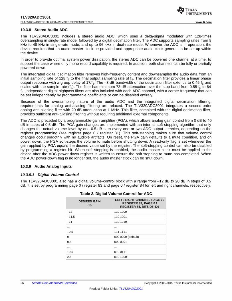
10.3.9.1 Digital Volume ControlThe TLV320ADC3001 also has a digital volume-control block with a range from –12 dB to 20 dB in steps of 0.5dB. It is set by programming page 0 / register 83 and page 0 / register 84 for left and right channels, respectively.
Table 2. Digital Volume Control for ADCLEFT / RIGHT CHANNEL PAGE 0 /DESIRED GAIN REGISTER 83, PAGE 0 /dB REGISTER 84, BITS D6–D0
–12 110 1000–11.5 110 1001–11 110 1010... ...–0.5 111 11110 000 0000 (default)0.5 000 0001... ...19.5 010 011120 010 1000
26 Submit Documentation Feedback Copyright © 2008–2015, Texas Instruments Incorporated
Product Folder Links: TLV320ADC3001

TLV320ADC3001www.ti.com SLAS548D –OCTOBER 2008–REVISED SEPTEMBER 2015
During volume control changes, the soft-stepping feature is used to avoid audible artifacts. The soft-stepping ratecan be set to either 1 or 2 gain steps per sample. Soft-stepping can also be entirely disabled. This soft-steppingis configured via page 0 / register 81, bits D1–D0, and is common to soft-stepping control for the analog PGA.During power-down of an ADC channel, this volume control soft-steps down to –12 dB before powering down.Due to the soft-stepping control, soon after changing the volume control setting or powering down the ADCchannel, the actual applied gain may be different from the one programmed through the control register. TheTLV320ADC3001 gives feedback to the user through read-only flags page 0 / register 36, bit D7 for the leftchannel and page 0 / register 36, bit D3 for the right channel.
10.3.9.2 Fine Digital Gain AdjustmentAdditionally, the gain in each of the channels is finely adjustable in steps of 0.1 dB. This is useful when trying tomatch the gain between channels. By programming page 0 / register 82, the gain can be adjusted from 0 dB to–0.4 dB in steps of 0.1 dB. This feature, in combination with the regular digital volume control, allows the gainsthrough the left and right channels be matched in the range of –0.5 dB to 0.5 dB with a resolution of 0.1 dB.
10.3.9.3 AGCThe TLV320ADC3001 includes automatic gain control (AGC) for ADC recording. AGC can be used to maintain anominally-constant output level when recording speech. As opposed to manually setting the PGA gain, in theAGC mode, the circuitry automatically adjusts the PGA gain as the input signal becomes overly loud or weak,such as when a person speaking into a microphone moves closer to or farther from the microphone. The AGCalgorithm has several programmable parameters, including target gain, attack and decay time constants, noisethreshold, and max PGA applicable, that allow the algorithm to be fine-tuned for any particular application. Thealgorithm uses the absolute average of the signal (which is the average of the absolute value of the signal) as ameasure of the nominal amplitude of the output signal. Because the gain can be changed at the sample intervaltime, the AGC algorithm operates at the ADC sample rate.• Target level represents the nominal output level at which the AGC attempts to hold the ADC output signal
level. The TLV320ADC3001 allows programming of eight different target levels, which can be programmedfrom –5.5 dB to –24 dB relative to a full-scale signal. Because the TLV320ADC3001 reacts to the signalabsolute average and not to peak levels, it is recommended that the target level be set with enough margin toavoid clipping at the occurrence of loud sounds.
• Attack time determines how quickly the AGC circuitry reduces the PGA gain when the output signal levelexceeds the target level due to increase in input signal level. A wide range of attack-time programmability issupported in terms of number of samples (that is, number of ADC sample-frequency clock cycles).
• Decay time determines how quickly the PGA gain is increased when the output signal level falls below thetarget level due to reduction in input signal level. A wide range of decay time programmability is supported interms of number of samples (that is, number of ADC sample-frequency clock cycles).
• Noise threshold is a reference level. If the input speech average value falls below the noise threshold, theAGC considers it as a silence and hence brings down the gain to 0 dB in steps of 0.5 dB every sample periodand sets the noise-threshold flag. The gain stays at 0 dB unless the input speech signal average rises abovethe noise threshold setting. This ensures that noise is not amplified in the absence of speech. Noise thresholdlevel in the AGC algorithm is programmable from –30 dB to –90 dB of full-scale. When the AGC noisethreshold is set to –70 dB, –80 db, or –90 dB, the microphone input max PGA applicable setting must begreater than or equal to 11.5 dB, 21.5 dB, or 31.5 dB, respectively. This operation includes hysteresis anddebounce to avoid the AGC gain from cycling between high gain and 0 dB when signals are near the noisethreshold level. The noise (or silence) detection feature can be entirely disabled by the user.
• Max PGA applicable allows the designer to restrict the maximum gain applied by the AGC. This can be usedfor limiting PGA gain in situations where environmental noise is greater than the programmed noise threshold.Microphone input Max PGA applicable can be programmed from 0 dB to 40 dB in steps of 0.5 dB.
• Hysteresis, as the name suggests, determines a window around the noise threshold which must beexceeded to detect that the recorded signal is indeed either noise or signal. If initially the energy of therecorded signal is greater than the noise threshold, then the AGC recognizes it as noise only when theenergy of the recorded signal falls below the noise threshold by a value given by hysteresis. Similarly, afterthe recorded signal is recognized as noise, for the AGC to recognize it as a signal, its energy must exceedthe noise threshold by a value given by the hysteresis setting. In order to prevent the AGC from jumpingbetween noise and signal states, (which can happen when the energy of recorded signal is close to the noisethreshold) a non-zero hysteresis value must be chosen. The hysteresis feature can also be disabled.
• Debounce time (noise and signal) determines the hysteresis in time domain for noise detection. The AGC
Copyright © 2008–2015, Texas Instruments Incorporated Submit Documentation Feedback 27
Product Folder Links: TLV320ADC3001

10 1
15 11
N + N zH(z) =
2 D z
-
-
-
TLV320ADC3001SLAS548D –OCTOBER 2008–REVISED SEPTEMBER 2015 www.ti.com
continuously calculates the energy of the recorded signal. If the calculated energy is less than the set noisethreshold, then the AGC does not increase the input gain to achieve the target level. However, to handleaudible artifacts which can occur when the energy of the input signal is close to the noise threshold, the AGCchecks if the energy of the recorded signal is less than the noise threshold for a time greater than the noisedebounce time. Similarly, the AGC starts increasing the input-signal gain to reach the target level when thecalculated energy of the input signal is greater than the noise threshold. Again, to avoid audible artifacts whenthe input-signal energy is close to noise threshold, the energy of the input signal must continuously exceedthe noise threshold value for the signal-debounce time. If the debounce times are kept small, then audibleartifacts can result by rapid enabling and disabling the AGC function. At the same time, if the debounce timeis kept too large, then the AGC may take time to respond to changes in levels of input signals with respect tothe noise threshold. Both noise and signal-debounce time can be disabled.
• The AGC noise-threshold flag is a read-only flag indicating that the input signal has levels lower than thenoise threshold, and thus is detected as noise (or silence). In such a condition, the AGC applies a gain of 0dB.
• Gain applied by AGC is a ready-only register setting which gives a real-time feedback to the system on thegain applied by the AGC to the recorded signal. This, along with the target setting, can be used to determinethe input signal level. In a steady-state situationTarget Level (dB ) = Gain Applied by AGC (dB) + Input Signal Level (dB)When the AGC noise threshold flag is set, then the status of gain applied by AGC is not valid.
• The AGC saturation flag is a read-only flag indicating that the ADC output signal has not reached its targetlevel. However, the AGC is unable to increase the gain further because the required gain is higher than themaximum allowed PGA gain. Such a situation can happen when the input signal has low energy and thenoise threshold is also set low. When the AGC noise threshold flag is set, the status of AGC saturation flagmust be ignored.
• The ADC saturation flag is a read-only flag indicating an overflow condition in the ADC channel. Onoverflow, the signal is clipped and distortion results. This typically happens when the AGC target level is kepthigh and the energy in the input signal increases faster than the attack time.
• An AGC lowpass filter is used to help determine the average level of the input signal. This average level iscompared to the programmed detection levels in the AGC to provide the correct functionality. This lowpassfilter is in the form of a first-order IIR filter. Two 8-bit registers are used to form the 16-bit digital coefficient asshown on the register map. In this way, a total of 6 registers are programmed to form the three IIRcoefficients. The transfer function of the filter implemented for signal level detection is given by
where• Coefficient N0 can be programmed by writing into page 4 / register 2 and page 4 / register 3.• Coefficient N1 can be programmed by writing into page 4 / register 4 and page 4 / register 5.• Coefficient D1 can be programmed by writing into page 4 / register 6 and page 4 / register 7.• N0, N1, and D1 are 16-bit 2s-complement numbers and their default values implement a lowpass filter with
cutoff at 0.002735 × ADC_fS . (2)See Table 3 for various AGC programming options. AGC can be used only if the analog microphone input isrouted to the ADC channel.
Table 3. AGC Parameter SettingsCONTROL REGISTER CONTROL REGISTERFUNCTION BITLEFT ADC RIGHT ADC
AGC enable Page 0 / register 86 Page 0 / register 94 D(7)Target Level Page 0 / register 86 Page 0 / register 94 D(6:4)Hysteresis Page 0 / register 87 Page 0 / register 95 D(7:6)Noise threshold Page 0 / register 87 Page 0 / register 95 D(5:1)Max PGA applicable Page 0 / register 88 Page 0 / register 96 D(6:0)Time constants (attack time) Page 0 / register 89 Page 0 / register 97 D(7:0)Time constants (decay time) Page 0 / register 90 Page 0 / register 98 D(7:0)
28 Submit Documentation Feedback Copyright © 2008–2015, Texas Instruments Incorporated
Product Folder Links: TLV320ADC3001

Target
Level
Input
Signal
Output
Signal
AGC
Gain
AttackTime
Decay Time
TLV320ADC3001www.ti.com SLAS548D –OCTOBER 2008–REVISED SEPTEMBER 2015
Table 3. AGC Parameter Settings (continued)CONTROL REGISTER CONTROL REGISTERFUNCTION BITLEFT ADC RIGHT ADC
Debounce time (noise) Page 0 / register 91 Page 0 / register 99 D(4:0)Debounce time (signal) Page 0 / register 92 Page 0 / register 100 D(3:0)Gain applied by AGC Page 0 / register 93 Page 0 / register 101 D(7:0) (read-only)AGC noise threshold flag Page 0 / register 45 (sticky flag), Page 0 / register 45 (sticky flag), D(6:5) (read-only)
Page 0 / register 47 (non-sticky flag) Page 0 / register 47 (non-sticky flag)AGC saturation flag Page 0 / register 36 (sticky flag) Page 0 / register 36 (sticky flag) D(5), D(1) (read-only)ADC saturation flag Page 0 / register 42 (sticky flag), Page 0 / register 42 (sticky flag), D(3:2) (read-only)
Page 0 / register 43 (non-sticky flag) Page 0 / register 43 (non-sticky flag)
Figure 28. AGC Characteristics
The TLV320ADC3001 includes three analog audio input pins, which can be configured as one fully-differentialpair and one single-ended input, or as three single-ended audio inputs. These pins connect through seriesresistors and switches to the virtual ground terminals of two fully differential operational amplifiers (one perADC/PGA channel). By selecting to turn on only one set of switches per operational amplifier at a time, the inputscan be effectively multiplexed to each ADC PGA channel.
By selecting to turn on multiple sets of switches per operational amplifier at a time, mixing can also be achieved.Mixing of multiple inputs can easily lead to PGA outputs that exceed the range of the internal operationalamplifiers, resulting in saturation and clipping of the mixed output signal. Whenever mixing is being implemented,the user must take adequate precautions to avoid such a saturation case from occurring. In general, the mixedsignal must not exceed 2 Vpp (single-ended) or 4 Vpp (differential).
In most mixing applications, there is also a general need to adjust the levels of the individual signals beingmixed. For example, if a soft signal and a large signal are to be mixed and played together, the soft signalgenerally must be amplified to a level comparable to the large signal before mixing. In order to accommodate thisneed, the TLV320ADC3001 includes input level control on each of the individual inputs before they are mixed ormultiplexed into the ADC PGAs, with programmable attenuation at 0 dB, –6 dB, or off.
Copyright © 2008–2015, Texas Instruments Incorporated Submit Documentation Feedback 29
Product Folder Links: TLV320ADC3001

PGA
0/+40 dB0.5 dB steps
ADC
AGC
PGA
0/+40 dB0.5 dB steps
ADC
AGC
+-
+
+-
+
+
--
+
--
IN1L(P)
IN2L
IN1R(M)
IN1L(P)
IN1R(M)
IN1L(P)
IN2L
IN1R(M)
IN1L(P)
IN1L(P)
IN1R(M)
IN1R(M)
All coarse stage attenuations are set to 0 dB, -6 dB, or Off by register setting.The default is all the switches are off at startup.
TLV320ADC3001SLAS548D –OCTOBER 2008–REVISED SEPTEMBER 2015 www.ti.com
NOTEThis input level control is not intended to be a volume control, but instead used for coarselevel setting. Finer soft-stepping of the input level is implemented in this device by theADC PGA.
Figure 29. TLV320ADC3001 Available Audio Input Path Configurations
Table 4. TLV320ADC3001 Audio SignalsAUDIO SIGNALS AVAILABLE TO LEFT ADC AUDIO SIGNALS AVAILABLE TO RIGHT ADC
SINGLE-ENDED INPUTS DIFFERENTIAL INPUTS SINGLE-ENDED INPUTS DIFFERENTIAL INPUTSIN1L(P) IN1L(P), IN1R(M) IN1R(M) IN1L(P), IN1R(M)
IN2L IN1L(P)IN1R(M)
Inputs can be selected as single-ended instead of fully-differential, and mixing or multiplexing into the ADC PGAsis also possible in this mode. It is not possible, however, for an input pair to be selected as fully-differential forconnection to one ADC PGA and simultaneously selected as single-ended for connection to the other ADC PGAchannel. However, it is possible for an input to be selected or mixed into both left- and right-channel PGAs, aslong as it has the same configuration for both channels (either both single-ended or both fully differential).
10.3.10 Input Impedance and VCM ControlThe TLV320ADC3001 includes several programmable settings to control analog input pins, particularly whenthey are not selected for connection to an ADC PGA. The default option allows unselected inputs to be put into ahigh-impedance state, such that the input impedance seen looking into the device is extremely high. However,the pins on the device do include protection diode circuits connected to AVDD and AVSS. Thus, if any voltage isdriven onto a pin approximately one diode drop (~0.6 V) above AVDD or one diode drop below AVSS, theseprotection diodes will begin conducting current, resulting in an effective impedance that no longer appears as ahigh-impedance state.
30 Submit Documentation Feedback Copyright © 2008–2015, Texas Instruments Incorporated
Product Folder Links: TLV320ADC3001

TLV320ADC3001www.ti.com SLAS548D –OCTOBER 2008–REVISED SEPTEMBER 2015
Another programmable option for unselected analog inputs is to weakly hold them at the common-mode inputvoltage of the ADC PGA (which is determined by an internal band-gap voltage reference). This is useful to keepthe ac-coupling capacitors connected to analog inputs biased up at a normal dc level, thus avoiding the need forthem to charge up suddenly when the input is changed from being unselected to selected for connection to anADC PGA. This option is controlled in page 1 / register 52 through page 1 / register 57. The user must specifythis option is disabled when an input is selected for connection to an ADC PGA or selected for the analog inputbypass path, because it can corrupt the recorded input signal if left operational when an input is selected.
In most cases, the analog input pins on the TLV320ADC3001 must be ac-coupled to analog input sources, theonly exception to this generally being if an ADC is being used for dc voltage measurement. The ac-couplingcapacitor causes a highpass filter pole to be inserted into the analog signal path, so the size of the capacitormust be chosen to move that filter pole sufficiently low in frequency to cause minimal effect on the processedanalog signal. The input impedance of the analog inputs when selected for connection to an ADC PGA varieswith the setting of the input level control, starting at approximately 35 kΩ with an input level control setting of 0dB, and 62.5 kΩ when the input level control is set at –6 dB. For example, using a 0.1-μF ac-coupling capacitorat an analog input will result in a highpass filter pole of 45.5 Hz when the 0-dB input level-control setting isselected. To set a highpass corner for the application, the following input impedance table (Table 5) has beenprovided with various mixer gains and microphone PGA ranges.
Table 5. Single-Ended Input Impedance vs PGA Ranges (1)
MIXER GAIN (dB) MICROPHONE PGA RANGE (dB) INPUT IMPEDANCE (Ω)0 0–5.5 35,0000 6–11.5 38,8890 12–17.5 42,0000 18–23.5 44,0740 24–29.5 45,2940 30–35.5 45,9600 36–40 46,308–6 0–5.5 62,222–6 6–11.5 70,000–6 12–17.5 77,778–6 18–23.5 84,000–6 24–29.5 88,148–6 30–35.5 90,588–6 36–40 91,919
(1) Valid when only one input is enabled
10.3.11 MICBIAS GenerationThe TLV320ADC3001 includes a programmable microphone bias output voltage (MICBIAS), capable of providingoutput voltages of 2 V or 2.5 V (both derived from the on-chip band-gap voltage) with 4-mA output-current drivecapability. In addition, the MICBIAS may be programmed to be switched to AVDD directly through an on-chipswitch, or it can be powered down completely when not needed, for power savings. This function is controlled byregister programming in page 1 / register 51.
10.3.12 ADC Decimation Filtering and Signal ProcessingThe TLV320ADC3001 ADC channel includes a built-in digital decimation filter to process the oversampled datafrom the delta-sigma modulator to generate digital data at the Nyquist sampling rate with high dynamic range.The decimation filter can be chosen from three different types, depending on the required frequency response,group delay, and sampling rate.
10.3.12.1 Processing BlocksThe TLV320ADC3001 offers a range of processing blocks which implement various signal processing capabilitiesalong with decimation filtering. These processing blocks give users the choice of how much and what type ofsignal processing they may use and which decimation filter is applied.
Copyright © 2008–2015, Texas Instruments Incorporated Submit Documentation Feedback 31
Product Folder Links: TLV320ADC3001

To AudioInterface
1st
OrderIIRx
AGCGain
Compen
Sation
AGC
To Analog PGA
Filter A
From Delta-SigmaModulator or
Digital Microphone
FromDigital Vol. Ctrl
TLV320ADC3001SLAS548D –OCTOBER 2008–REVISED SEPTEMBER 2015 www.ti.com
The signal processing blocks available are:• First-order IIR• Scalable number of biquad filters• Variable-tap FIR filter• AGC
The processing blocks are tuned for common cases and can achieve high anti-alias filtering or low group delay incombination with various signal processing effects such as audio effects and frequency shaping. The availablefirst order IIR, biquad, and FIR filters have fully user-programmable coefficients. ADC processing blocks can beselected by writing to page 0 / register 61. The default (reset) processing block is PRB_R1.
Table 6. ADC Processing Blocks1ST ORDERDECIMATION NUMBERPROCESSING REQUIRED AOSR RESOURCECHANNEL FIRIIRBLOCKS VALUE CLASSFILTER BIQUADSAVAILABLE
PRB_R1 Stereo A Yes 0 No 128, 64 6PRB_R2 Stereo A Yes 5 No 128, 64 8PRB_R3 Stereo A Yes 0 25-tap 128, 64 8PRB_R4 Right A Yes 0 No 128, 64 3PRB_R5 Right A Yes 5 No 128, 64 4PRB_R6 Right A Yes 0 25-tap 128, 64 4PRB_R7 Stereo B Yes 0 No 64 3PRB_R8 Stereo B Yes 3 No 64 4PRB_R9 Stereo B Yes 0 20-tap 64 4PRB_R10 Right B Yes 0 No 64 2PRB_R11 Right B Yes 3 No 64 2PRB_R12 Right B Yes 0 20-tap 64 2PRB_R13 Right C Yes 0 No 32 3PRB_R14 Stereo C Yes 5 No 32 4PRB_R15 Stereo C Yes 0 25-tap 32 4PRB_R16 Right C Yes 0 No 32 2PRB_R17 Right C Yes 5 No 32 2PRB_R18 Right C Yes 0 25-tap 32 2
10.3.12.2 Processing Blocks – Details
10.3.12.2.1 First-Order IIR, AGC, Filter A
Figure 30. Signal Chain for PRB_R1 and PRB_R4
32 Submit Documentation Feedback Copyright © 2008–2015, Texas Instruments Incorporated
Product Folder Links: TLV320ADC3001

To AudioInterface
1st
OrderIIRx
AGCGain
Compen
sation
AGC
Filter B
FromDigital Vol. Ctrl
To AudioInterface
To Analog PGA
From Delta-SigmaModulator or
Digital Microphone
1st
OrderIIRx
AGCGain
Compen
sation
AGC
Filter A 25-Tap FIR
From Delta-SigmaModulator or
Digital Microphone
FromDigital Vol. Ctrl
To Analog PGA
To Audio
Interface
1st
OrderIIRx
AGCGain
Compensation
AGC
Filter A H EH DH CHBH ATo Audio
Interface
To Analog PGA
From Delta-SigmaModulator or
Digital Microphone
FromDigital Vol. Ctrl
TLV320ADC3001www.ti.com SLAS548D –OCTOBER 2008–REVISED SEPTEMBER 2015
10.3.12.2.2 Five Biquads, First-Order IIR, AGC, Filter A
Figure 31. Signal Chain for PRB_R2 and PRB_R5
10.3.12.2.3 25-Tap FIR, First-Order IIR, AGC, Filter A
Figure 32. Signal Chain for PRB_R3 and PRB_R6
10.3.12.2.4 First-Order IIR, AGC, Filter B
Figure 33. Signal Chain for PRB_R7 and PRB_R10
Copyright © 2008–2015, Texas Instruments Incorporated Submit Documentation Feedback 33
Product Folder Links: TLV320ADC3001

1st
OrderIIRx
AGCGain
Compen
sation
AGC
Filter C
From Delta-SigmaModulator or
Digital Microphone
FromDigital Vol. Ctrl
To Analog PGA
To AudioInterface
1st
OrderIIRx
AGCGain
Compen
sation
AGC
Filter B 20-Tap FIR
From Delta-SigmaModulator or
Digital Microphone
FromDigital Vol. Ctrl
To Analog PGA
To Audio
Interface
1st
OrderIIRx
AGCGain
Compensation
AGC
Filter B HCHBHA
From Delta-SigmaModulator or
Digital Microphone
FromDigital Vol. Ctrl
To Analog PGA
To Audio
Interface
TLV320ADC3001SLAS548D –OCTOBER 2008–REVISED SEPTEMBER 2015 www.ti.com
10.3.12.2.5 Three Biquads, First-Order IIR, AGC, Filter B
Figure 34. Signal Chain for PRB_R8 and PRB_R11
10.3.12.2.6 20-Tap FIR, First-Order IIR, AGC, Filter B
Figure 35. Signal Chain for PRB_R9 and PRB_R12
10.3.12.2.7 First-Order IIR, AGC, Filter C
Figure 36. Signal Chain for PRB_R13 and PRB_R16
34 Submit Documentation Feedback Copyright © 2008–2015, Texas Instruments Incorporated
Product Folder Links: TLV320ADC3001

10 1
15 11
N + N zH(z) =
2 D z
-
-
-
1st
OrderIIR
x
AGCGain
Compen
sation
AGC
Filter C 25-Tap FIR
From Delta-SigmaModulator or
Digital Microphone
FromDigital Vol. Ctrl
To Analog PGA
To Audio
Interface
1st
OrderIIRx
AGCGain
Compensation
AGC
Filter C H EH DH CHBH A
From Delta-SigmaModulator or
Digital Microphone
FromDigital Vol. Ctrl
To Analog PGA
To Audio
Interface
TLV320ADC3001www.ti.com SLAS548D –OCTOBER 2008–REVISED SEPTEMBER 2015
10.3.12.2.8 Five Biquads, First-Order IIR, AGC, Filter C
Figure 37. Signal Chain for PRB_R14 and PRB_R17
10.3.12.2.9 25-Tap FIR, First-Order IIR, AGC, Filter C
Figure 38. Signal for PRB_R15 and PRB_R18
10.3.12.3 User-Programmable FiltersDepending on the selected processing block, different types and orders of digital filtering are available. A first-order IIR filter is always available, and is useful to filter out possible dc components of the signal efficiently. Up tofive biquad sections, or alternatively up to 25-tap FIR filters, are available for specific processing blocks. Thecoefficients of the available filters are arranged as sequentially indexed coefficients in two banks. If adaptivefiltering is chosen, the coefficient banks can be switched in real time.
The coefficients of these filters are each 16-bits wide, in 2s-complement and occupy two consecutive 8-bitregisters in the register space. Table 7.
10.3.12.3.1 First-Order IIR Section
The transfer function for the first-order IIR filter is given by Equation 3.
(3)
The frequency response for the first-order IIR section with default coefficients is flat at a gain of 0 dB.
Table 7. ADC 1st order IIR Filter CoefficientsFILTER FILTER COEFFICIENT ADC COEFFICIENT, LEFT CHANNEL ADC COEFFICIENT, RIGHT CHANNEL
N0 C4 (page 4 / register 8 and page 4 / C36 (page 4 / register 72 and page 4 /register 9) register 73)
N1 C5 (page 4 / register 10 and page 4 / C37 (page 4 / register 74 and page 4 /First-order IIR register 11) register 75)D1 C6 (page 4 / register 12 and page 4 / C38 (page 4 / register 76 and page 4 /
register 13) register 77)
Copyright © 2008–2015, Texas Instruments Incorporated Submit Documentation Feedback 35
Product Folder Links: TLV320ADC3001

PRB_R12andPRB_R9for,19M
PRB_R18andPRB_R15PRB_R6,PRB_R3,for,24M
zFir)z(HM
0n
nn
=
=
= å=
-
1 20 1 2
15 1 21 2
N + 2 × N z + N zH(z) =
2 2 D z D z
- -
- -
- ´ -
TLV320ADC3001SLAS548D –OCTOBER 2008–REVISED SEPTEMBER 2015 www.ti.com
10.3.12.3.2 Biquad Section
The transfer function of each of the biquad filters is given by Equation 4.
(4)
The frequency response for each of the biquad sections with default coefficients is flat at a gain of 0 dB.
Table 8. ADC Biquad Filter CoefficientsFILTER
FILTER COEFFICIEN ADC COEFFICIENT, LEFT CHANNEL ADC COEFFICIENT, RIGHT CHANNELT
N0 C7 (page 4 / register 14 and page 4 / register 15) C39 (page 4 / register 78 and page 4 / register 79)N1 C8 (page 4 / register 16 and page 4 / register 17) C40 (page 4 / register 80 and page 4 / register 81)
Biquad A N2 C9 (page 4 / register 18 and page 4 / register 19) C41 (page 4 / register 82 and page 4 / register 83)D1 C10 (page 4 / register 20 and page 4 / register 21) C42 (page 4 / register 84 and page 4 / register 85)D2 C11 (page 4 / register 22 and page 4 / register 23) C43 (page 4 / register 86 and page 4 / register 87)N0 C12 (page 4 / register 24 and page 4 / register 25) C44 (page 4 / register 88 and page 4 / register 89)N1 C13 (page 4 / register 26 and page 4 / register 27) C45 (page 4 / register 90 and page 4 / register 91)
Biquad B N2 C14 (page 4 / register 28 and page 4 / register 29) C46 (page 4 / register 92 and page 4 / register 93)D1 C15 (page 4 / register 30 and page 4 / register 31) C47 (page 4 / register 94 and page 4 / register 95)D2 C16 (page 4 / register 32 and page 4 / register 33) C48 (page 4 / register 96 and page 4 / register 97)N0 C17 (page 4 / register 34 and page 4 / register 35) C49 (page 4 / register 98 and page 4 / register 99)N1 C18 (page 4 / register 36 and page 4 / register 37) C50 (page 4 / register 100 and page 4 / register 101)
Biquad C N2 C19 (page 4 / register 38 and page 4 / register 39) C51 (page 4 / register 102 and page 4 / register 103)D1 C20 (page 4 / register 40 and page 4 / register 41) C52 (page 4 / register 104 and page 4 / register 105)D2 C21 (page 4 / register 42 and page 4 / register 43) C53 (page 4 / register 106 and page 4 / register 107)N0 C22 (page 4 / register 44 and page 4 / register 45) C54 (page 4 / register 108 and page 4 / register 109)N1 C23 (page 4 / register 46 and page 4 / register 47) C55 (page 4 / register 110 and page 4 / register 111)
Biquad D N2 C24 (page 4 / register 48 and page 4 / register 49) C56 (page 4 / register 112 and page 4 / register113)D1 C25 (page 4 / register 50 and page 4 / register 51) C57 (page 4 / register 114 and page 4 / register 115)D2 C26 (page 4 / register 52 and page 4 / register 53) C58 (page 4 / register 116 and page 4 / register 117)N0 C27 (page 4 / register 54 and page 4 / register 55) C59 (page 4 / register 118 and page 4 / register 119)N1 C28 (page 4 / register 56 and page 4 / register 57) C60 (page 4 / register 120 and page 4 / register 121)
Biquad E N2 C29 (page 4 / register 58 and page 4 / register 59) C61 (page 4 / register 122 and page 4 / register 123)D1 C30 (page 4 / register 60 and page 4 / register 61) C62 (page 4 / register 124 and page 4 / register 125)D2 C31 (page 4 / register 62 and page 4 / register 63) C63 (page 4 / register 126 and page 4 / register 127)
10.3.12.3.3 FIR Section
Six of the available ADC processing blocks offer FIR filters for signal processing. PRB_R9 and PRB_R12 featurea 20-tap FIR filter, whereas the processing blocks PRB_R3, PRB_R6, PRB_R15, and PRB_R18 feature a 25-tapFIR filter
(5)
The coefficients of the FIR filters are 16-bit 2s-complement format and correspond to the ADC coefficient spaceas listed in Table 9. There is no default transfer function for the FIR filter. When the FIR filter is used, allapplicable coefficients must be programmed.
36 Submit Documentation Feedback Copyright © 2008–2015, Texas Instruments Incorporated
Product Folder Links: TLV320ADC3001

TLV320ADC3001www.ti.com SLAS548D –OCTOBER 2008–REVISED SEPTEMBER 2015
Table 9. ADC FIR Filter CoefficientsFILTER COEFFICIENT ADC COEFFICIENT LEFT CHANNEL ADC COEFFICIENT RIGHT CHANNEL
Fir0 C7 (page 4 / register 14 and page 4 / register 15) C39 (page 4 / register 78 and page 4 / register 79)Fir1 C8 (page 4 / register 16 and page 4 / register 17) C40 (page 4 / register 80 and page 4 / register 81)Fir2 C9 (page 4 / register 18 and page 4 / register 19) C41 (page 4 / register 82 and page 4 / register 83)Fir3 C10 (page 4 / register 20 and page 4 / register 21) C42 (page 4 / register 84 and page 4 / register 85)Fir4 C11 (page 4 / register 22 and page 4 / register 23) C43 (page 4 / register 86 and page 4 / register 87)Fir5 C12 (page 4 / register 24 and page 4 / register 25) C44 (page 4 / register 88 and page 4 / register 89)Fir6 C13 (page 4 / register 26 and page 4 / register 27) C45 (page 4 / register 90 and page 4 / register 91)Fir7 C14 (page 4 / register 28 and page 4 / register 29) C46 (page 4 / register 92 and page 4 / register 93)Fir8 C15 (page 4 / register 30 and page 4 / register 31) C47 (page 4 / register 94 and page 4 / register 95)Fir9 C16 (page 4 / register 32 and page 4 / register 33) C48 (page 4 / register 96 and page 4 / register 97)Fir10 C17 (page 4 / register 34 and page 4 / register 35) C49 (page 4 / register 98 and page 4 / register 99)Fir11 C18 (page 4 / register 36 and page 4 / register 37) C50 (page 4 / register 100 and page 4 / register 101)Fir12 C19 (page 4 / register 38 and page 4 / register 39) C51 (page 4 / register 102 and page 4 / register 103)Fir13 C20 (page 4 / register 40 and page 4 / register 41) C52 (page 4 / register 104 and page 4 / register 105)Fir14 C21 (page 4 / register 42 and page 4 / register 43) C53 (page 4 / register 106 and page 4 / register 107)Fir15 C22 (page 4 / register 44 and page 4 / register 45) C54 (page 4 / register 108 and page 4 / register 109)Fir16 C23 (page 4 / register 46 and page 4 / register 47) C55 (page 4 / register 110 and page 4 / register 111)Fir17 C24 (page 4 / register 48 and page 4 / register 49) C56 (page 4 / register 112 and page 4 / register113)Fir18 C25 (page 4 / register 50 and page 4 / register 51) C57 (page 4 / register 114 and page 4 / register 115)Fir19 C26 (page 4 / register 52 and page 4 / register 53) C58 (page 4 / register 116 and page 4 / register 117)Fir20 C27 (page 4 / register 54 and page 4 / register 55) C59 (page 4 / register 118 and page 4 / register 119)Fir21 C28 (page 4 / register 56 and page 4 / register 57) C60 (page 4 / register 120 and page 4 / register 121)Fir22 C29 (page 4 / register 58 and page 4 / register 59) C61 (page 4 / register 122 and page 4 / register 123)Fir23 C30 (page 4 / register 60 and page 4 / register 61) C62 (page 4 / register 124 and page 4 / register 125)Fir24 C31 (page 4 / register 62 and page 4 / register 63) C63 (page 4 / register 126 and page 4 / register 127)
10.3.12.4 Decimation FilterThe TLV320ADC3001 offers three different types of decimation filters. The integrated digital decimation filterremoves high-frequency content and downsamples the audio data from an initial sampling rate of AOSR × fS tothe final output sampling rate of fS. The decimation filtering is achieved using a higher-order CIC filter followed bylinear-phase FIR filters. The decimation filter cannot be chosen by itself, it is implicitly set through the chosenprocessing block.
The following subsections describe the properties of the available filters A, B, and C.
Copyright © 2008–2015, Texas Instruments Incorporated Submit Documentation Feedback 37
Product Folder Links: TLV320ADC3001

0
–10
–20
–30
–40
–50
–60
–70
–80
–90
–100
0.0 0.2 0.4 0.6 0.8 1.0 1.2 1.4 1.6 1.8 2.0
Frequency Normalized to fS
Magnitude
–dB
ADC Channel Response for Decimation Filter A(Red line corresponds to –73 dB)
G013
TLV320ADC3001SLAS548D –OCTOBER 2008–REVISED SEPTEMBER 2015 www.ti.com
10.3.12.4.1 Decimation Filter A
This filter is intended for use at sampling rates up to 48 kHz. When configuring this filter, the oversampling ratioof the ADC can either be 128 or 64. For highest performance, the oversampling ratio must be set to 128. Filter Acan also be used for 96 kHz at an AOSR of 64.
Table 10. ADC Decimation Filter A, SpecificationPARAMETER CONDITION VALUE (TYPICAL) UNIT
AOSR = 128Filter gain pass band 0…0.39 fS 0.062 dBFilter gain stop band 0.55…64 fS –73 dBFilter group delay 17/fS sPass-band ripple, 8 ksps 0…0.39 fS 0.062 dBPass-band ripple, 44.18 ksps 0…0.39 fS 0.05 dBPass-band ripple, 48 ksps 0…0.39 fS 0.05 dBAOSR = 64Filter gain pass band 0…0.39 fS 0.062 dBFilter gain stop band 0.55…32 fS –73 dBFilter group delay 17/fS sPass-band ripple, 8 ksps 0…0.39 fS 0.062 dBPass-band ripple, 44.18 ksps 0…0.39 fS 0.05 dBPass-band ripple, 48 ksps 0…0.39 fS 0.05 dBPass-band ripple, 96 ksps 0…20 kHz 0.1 dB
Figure 39. ADC Decimation Filter A, Frequency Response
38 Submit Documentation Feedback Copyright © 2008–2015, Texas Instruments Incorporated
Product Folder Links: TLV320ADC3001

0
–10
–20
–30
–40
–50
–60
–70
–80
–90
0.0 0.2 0.4 0.6 0.8 1.0 1.2 1.4 1.6 1.8 2.0
Frequency Normalized to fS
Magnitude
–dB
ADC Channel Response for Decimation Filter B(Red line corresponds to –44 dB)
G014
TLV320ADC3001www.ti.com SLAS548D –OCTOBER 2008–REVISED SEPTEMBER 2015
10.3.12.4.2 Decimation Filter B
Filter B is intended to support sampling rates up to 96kHz at a oversampling ratio of 64.
Table 11. ADC Decimation Filter B, SpecificationsPARAMETER CONDITION VALUE (TYPICAL) UNIT
AOSR = 64Filter gain pass band 0…0.39 fS ±0.077 dBFilter gain stop band 0.60 fS…32 fS –46 dBFilter group delay 11/fS sPass-band ripple, 8 ksps 0…0.39 fS 0.076 dBPass-band ripple, 44.18 ksps 0…0.39 fS 0.06 dBPass-band ripple, 48 ksps 0…0.39 fS 0.06 dBPass-band ripple, 96 ksps 0…20kHz 0.11 dB
Figure 40. ADC Decimation Filter B, Frequency Response
Copyright © 2008–2015, Texas Instruments Incorporated Submit Documentation Feedback 39
Product Folder Links: TLV320ADC3001

ADC Channel Response for Decimation Filter C(Red line corresponds to –60 dB)
0
–20
–40
–60
–100
–80
–120
0.0 0.2 0.4 0.6 0.8 1.0 1.2 1.4 1.6 1.8 2.0
Frequency Normalized to fS
Magnitude
–dB
G015
TLV320ADC3001SLAS548D –OCTOBER 2008–REVISED SEPTEMBER 2015 www.ti.com
10.3.12.4.3 Decimation Filter C
Filter type C along with AOSR of 32 is specially designed for 192ksps operation for the ADC. The pass bandwhich extends up to 0.11 × fS (corresponds to 21 kHz), is suited for audio applications.
Table 12. ADC Decimation Filter C, SpecificationsPARAMETER CONDITION VALUE (TYPICAL) UNIT
Filter gain from 0 to 0.11 fS 0…0.11 fS ±0.033 dBFilter gain from 0.28 fS to 16 fS 0.28 fS…16 fS –60 dBFilter group delay 11/ fS sPass-band ripple, 8 ksps 0…0.11 fS 0.033 dBPass-band ripple, 44.18 ksps 0…0.11 fS 0.033 dBPass-band ripple, 48 ksps 0…0.11 fS 0.032 dBPass-band ripple, 96 ksps 0…0.11 fS 0.032 dBPass-band ripple, 192 ksps 0…20 kHz 0.086 dB
Figure 41. ADC Decimation Filter C, Frequency Response
10.4 Device Functional Modes
10.4.1 Recording ModeThe recording mode is activated once the ADC blocks are enabled. The record path operates from 8 kHz to48 kHz in single-rate mode and up to 96 kHz in dual-rate mode. It contains programmable input channelconfigurations supporting single-ended and differential setups. To provide optimal system power management,the stereo recording path can be powered up one channel at a time, to support the case where only mono recordcapability is required. Digital signal processing blocks can remove audible noise that may be introduced bymechanical coupling. The TLV320ADC3001 includes Automatic Gain Control (AGC) for ADC recording.
10.5 Programming
10.5.1 Digital Interfaces
10.5.1.1 I2C Control ModeThe TLV320ADC3001 supports the I2C control protocol using 7-bit addressing and is capable of operating in bothstandard mode (≤ 100 kHz) and fast mode (≤ 400 kHz). The device address is fixed with the value 0011 000.
40 Submit Documentation Feedback Copyright © 2008–2015, Texas Instruments Incorporated
Product Folder Links: TLV320ADC3001

DA(6) DA(0) RA(7) RA(0) D(7) D(0)
Start
(M)
7-bit Device Address
(M)
Write
(M)
Slave
Ack(S)
8-bit Register Address
(M)
Slave
Ack(S)
8-bit Register Data
(M)
Stop
(M)
Slave
Ack(S)
SDA
SCL
(M) => SDA Controlled by Master
(S) => SDA Controlled by Slave
TLV320ADC3001www.ti.com SLAS548D –OCTOBER 2008–REVISED SEPTEMBER 2015
Programming (continued)I2C is a two-wire, open-drain interface supporting multiple devices and masters on a single bus. Devices on theI2C bus only drive the bus lines LOW by connecting them to ground; they never drive the bus lines HIGH.Instead, the bus wires are pulled HIGH by pullup resistors, so the bus wires are HIGH when no device is drivingthem LOW. This way, two devices cannot conflict; if two devices drive the bus simultaneously, there is no drivercontention.
Communication on the I2C bus always takes place between two devices, one acting as the master and the otheracting as the slave. Both masters and slaves can read and write, but slaves can only do so under the direction ofa master. Some I2C devices can act as masters or slaves, but the TLV320ADC3001 can only act as a slavedevice.
An I2C bus consists of two lines, SDA and SCL. SDA carries data; SCL provides the clock. All data is transmittedacross the I2C bus in groups of eight bits. To send a bit on the I2C bus, the SDA line is driven to the appropriatelevel while SCL is LOW (a LOW on SDA indicates the bit is 0; a HIGH indicates the bit is 1). Once the SDA linehas settled, the SCL line is brought HIGH, then LOW. This pulse on SCL clocks the SDA bit into the receivershift register.
The I2C bus is bidirectional: the SDA line is used both for transmitting and receiving data. When a master readsfrom a slave, the slave drives the data line; when a master sends to a slave, the master drives the data line.Under normal circumstances, the master drives the clock line.
Most of the time the bus is idle, no communication is taking place, and both lines are HIGH. Whencommunication is taking place, the bus is active. Only master devices can start a communication. They do this bycausing a START condition on the bus. Normally, the data line is only allowed to change state while the clockline is LOW. If the data line changes state while the clock line is HIGH, it is either a START condition or itscounterpart, a STOP condition. A START condition is when the clock line is HIGH and the data line goes fromHIGH to LOW. A STOP condition is when the clock line is HIGH and the data line goes from LOW to HIGH.
After the master issues a START condition, it sends a byte that indicates the slave device with which it is tocommunicate. This byte is called the address byte. Each device on an I2C bus has a unique 7-bit address towhich it responds. (Slaves can also have 10-bit addresses; see the I2C specification for details.) The mastersends an address in the address byte, together with a bit that indicates whether it is to read from or write to theslave device.
Every byte transmitted on the I2C bus, whether it is address or data, is acknowledged with an acknowledge bit.When a master has finished sending a byte (eight data bits) to a slave, it stops driving SDA and waits for theslave to acknowledge the byte. The slave acknowledges the byte by pulling SDA LOW. The master then sends aclock pulse to clock the acknowledge bit. Similarly, when a master has finished reading a byte, it pulls SDA LOWto acknowledge this to the slave. It then sends a clock pulse to clock the bit.
A not-acknowledge is performed by leaving SDA HIGH during an acknowledge cycle. If a device is not presenton the bus, and the master attempts to address it, it receives a not-acknowledge because no device is present atthat address to pull the line LOW.
When a master has finished communicating with a slave, it may issue a STOP condition. When a STOPcondition is issued, the bus becomes idle again. A master may also issue another START condition. When aSTART condition is issued while the bus is active, it is called a repeated START condition.
The TLV320ADC3001 also responds to and acknowledges a general call, which consists of the master issuing acommand with a slave address byte of 00h.
Figure 42. I2C Write
Copyright © 2008–2015, Texas Instruments Incorporated Submit Documentation Feedback 41
Product Folder Links: TLV320ADC3001

DA(6) DA(0) RA(7) RA(0)
Start
(M)7-bit Device Address
(M)
Write
(M)
SlaveAck
(S)
8-bit Register Address
(M)
SlaveAck
(S)
SDA
SCL
DA(6) DA(0)
7-bit Device Address
(M)
Read
(M)
SlaveAck
(S)
D(7) D(0)
8-bit Register Data
(S)
Stop
(M)
MasterNo Ack
(M)
RepeatStart
(M)
(M) => SDA Controlled by Master
(S) => SDA Controlled by Slave
TLV320ADC3001SLAS548D –OCTOBER 2008–REVISED SEPTEMBER 2015 www.ti.com
Programming (continued)
Figure 43. I2C Read
In the case of an I2C register write, if the master does not issue a STOP condition, then the device enters auto-increment mode. So in the next eight clocks, the data on SDA is treated as data for the next incremental register.
Similarly, in the case of an I2C register read, after the device has sent out the 8-bit data from the addressedregister, if the master issues an ACKNOWLEDGE, the slave takes over control of SDA bus and transmits for thenext eight clocks the data of the next incremental register.
10.6 Register Maps
10.6.1 Control RegistersThe control registers for the TLV320ADC3001 are described in detail as follows. All registers are 8 bits in width,with D7 referring to the most-significant bit of each register, and D0 referring to the least-significant bit.
Pages 0, 1, 4, 5, and 32–47 are available. All other pages are reserved. Do not read from or write to reservedpages.
42 Submit Documentation Feedback Copyright © 2008–2015, Texas Instruments Incorporated
Product Folder Links: TLV320ADC3001

TLV320ADC3001www.ti.com SLAS548D –OCTOBER 2008–REVISED SEPTEMBER 2015
Register Maps (continued)
Table 13. Page / Register MapREGISTER NO. REGISTER NAME
PAGE 0: (Clock Multipliers and Dividers, Serial Interfaces, Flags, Interrupts, and Programming of GPIOs)0 Page control register1 S/W RESET2 Reserved3 Reserved4 Clock-gen muxing5 PLL P and R-VAL6 PLL J-VAL7 PLL D-VAL MSB8 PLL D-VAL LSB
9–17 Reserved18 ADC NADC clock divider19 ADC MADC clock divider20 ADC AOSR21 ADC IADC22 ADC miniDSP engine decimation
23 and 24 Reserved25 CLKOUT MUX26 CLKOUT M divider27 ADC interface control 128 DATA slot offset programmability 1 (Ch_Offset_1)29 ADC interface control 230 BCLK N divider
31–33 Reserved34 I2S sync35 Reserved36 ADC flag register37 Data slot offset programmability 2 (Ch_Offset_2)38 I2S TDM control register
39–41 Reserved42 Interrupt flags (overflow)43 Interrupt flags (overflow)44 Reserved45 Interrupt flags-ADC46 Reserved47 Interrupt flags-ADC
48–52 Reserved53 DOUT (Out pin) Control
54–56 Reserved57 ADC sync control 158 ADC sync control 259 ADC CIC filter gain control60 Reserved61 ADC processing block / miniDSP selection62 Programmable instruction-mode control bits
63–80 Reserved
Copyright © 2008–2015, Texas Instruments Incorporated Submit Documentation Feedback 43
Product Folder Links: TLV320ADC3001

TLV320ADC3001SLAS548D –OCTOBER 2008–REVISED SEPTEMBER 2015 www.ti.com
Register Maps (continued)Table 13. Page / Register Map (continued)
REGISTER NO. REGISTER NAME81 ADC digital82 ADC fine volume control83 Left ADC volume control84 Right ADC volume control85 ADC phase compensation86 Left AGC control 187 Left AGC control 288 Left AGC maximum gain89 Left AGC attack time90 Left AGC decay time91 Left AGC noise debounce92 Left AGC signal debounce93 Left AGC gain94 Right AGC control 195 Right AGC control 296 Right AGC maximum gain97 Right AGC attack time98 Right AGC decay time99 Right AGC noise debounce
100 Right AGC signal debounce101 Right AGC gain
102–127 ReservedPAGE 1: (ADC ROUTING, PGA, POWER CONTROLS, AND MISC LOGIC-RELATED PROGRAMMABILITIES)
0 Page control register1–25 Reserved
26 Dither control27–50 Reserved
51 MICBIAS control52 Left ADC input selection for left PGA53 Reserved54 Left ADC input selection for left PGA55 Right ADC input selection for right PGA56 Reserved57 Right ADC input selection for right PGA58 Reserved59 Left analog PGA setting60 Right analog PGA setting61 ADC low-current modes62 ADC analog PGA flags
63–127 ReservedPAGE 2: Reserved. Do not read from or write to this page.PAGE 3: Reserved. Do not read from or write to this page.
44 Submit Documentation Feedback Copyright © 2008–2015, Texas Instruments Incorporated
Product Folder Links: TLV320ADC3001

TLV320ADC3001www.ti.com SLAS548D –OCTOBER 2008–REVISED SEPTEMBER 2015
Register Maps (continued)Table 13. Page / Register Map (continued)
REGISTER NO. REGISTER NAMEADC Digital Filter RAM and Instruction Pages:
PAGE 4: ADC Programmable Coefficients RAM (1:63)PAGE 5: ADC Programmable Coefficients RAM (65:127)
PAGE 6–PAGE 31: Reserved. Do not read from or write to these pages.PAGE 32–PAGE 47: ADC Programmable Instruction RAM (0:511)
Page 32 Instruction Inst(0:31)Page 33 Instruction Inst(32:63)Page 34 Instruction Inst(64:95)
...Page 47 Instruction Inst(480:511)
PAGE 48–PAGE 255: Reserved. Do not read from or write to these pages.
10.6.2 Control Registers, Page 0: Clock Multipliers and Dividers, Serial Interfaces, Flags, Interrupts andProgramming of GPIOs
Table 14. Page 0 / Register 0: Page Control Register (1)
READ/ RESETBIT DESCRIPTIONWRITE VALUED7–D0 R/W 0000 0000 0000 0000: Page 0 selected
0000 0001: Page 1 selected...1111 1110: Page 254 selected (reserved)1111 1111: Page 255 selected (reserved)
(1) Valid pages are 0, 1, 4, 5, 32–47. All other pages are reserved (do not access).
Table 15. Page 0 / Register 1: Software ResetREAD/ RESETBIT DESCRIPTIONWRITE VALUE
D7–D1 R 0000 000 Reserved. Write only zeros to these bits.D0 W 0 0: Don't care
1: Self-clearing software reset for control register
Table 16. Page 0 / Register 2: ReservedREAD/ RESETBIT DESCRIPTIONWRITE VALUE
D7–D0 R 0000 0000 Reserved. Do not write any value other than reset value.
Table 17. Page 0 / Register 3: ReservedREAD/ RESETBIT DESCRIPTIONWRITE VALUE
D7–D0 R XXXX XXXX Reserved. Do not write to this register.
Copyright © 2008–2015, Texas Instruments Incorporated Submit Documentation Feedback 45
Product Folder Links: TLV320ADC3001

TLV320ADC3001SLAS548D –OCTOBER 2008–REVISED SEPTEMBER 2015 www.ti.com
Table 18. Page 0 / Register 4: Clock-Gen Multiplexing (1)
READ/ RESETBIT DESCRIPTIONWRITE VALUED7–D4 R 0000 Reserved. Do not write any value other than reset value.D3–D2 R/W 00 00: PLL_CLKIN = MCLK (device pin)
01: PLL_CLKIN = BCLK (device pin)10: Reserved. Do not use.11: PLL_CLKIN = logic level 0
D1–D0 R/W 00 00: CODEC_CLKIN = MCLK (device pin)01: CODEC_CLKIN = BCLK (device pin)10: Reserved. Do not use.11: CODEC_CLKIN = PLL_CLK (generated on-chip)
(1) Refer to Figure 27 for more details on clock generation multiplexing and dividers.
Table 19. Page 0 / Register 5: PLL P and R-VALREAD/ RESETBIT DESCRIPTIONWRITE VALUE
D7 R/W 0 0: PLL is powered down.1: PLL is powered up.
D6–D4 R/W 001 000: PLL divider P = 8001: PLL divider P = 1010: PLL divider P = 2...110: PLL divider P = 6111: PLL divider P = 7
D3–D0 R/W 0001 0000: PLL multiplier R = 160001: PLL multiplier R = 10010: PLL multiplier R = 2...1110: PLL multiplier R = 141111: PLL multiplier R = 15
Table 20. Page 0 / Register 6: PLL J-VALREAD/ RESETBIT DESCRIPTIONWRITE VALUE
D7–D6 R/W 00 Reserved. Write only zeros to these bits.D5–D0 R/W 00 0100 00 0000: Don’t use (reserved)
00 0001: PLL multiplier J = 100 0010: PLL multiplier J = 200 0011: PLL multiplier J = 300 0100: PLL multiplier J = 4 (default)...11 1110: PLL multiplier J = 6211 1111: PLL multiplier J = 63
Table 21. Page 0 / Register 7: PLL D-VAL MSB (1)
READ/ RESETBIT DESCRIPTIONWRITE VALUED7–D6 R/W 00 Reserved. Write only zeros to these bits.D5–D0 R/W 00 0000 PLL fractional multiplier bits D13–D8
(1) Page 0 / register 7 is updated when page 0 / register 8 is written immediately after page 0 / register 7 is written.
Table 22. Page 0 / Register 8: PLL D-VAL LSB (1)
READ/ RESETBIT DESCRIPTIONWRITE VALUED7–D0 R/W 0000 0000 PLL fractional multiplier bits D7–D0
(1) Page 0 / register 8 must be written immediately after writing to page 0 / register 7.
46 Submit Documentation Feedback Copyright © 2008–2015, Texas Instruments Incorporated
Product Folder Links: TLV320ADC3001

TLV320ADC3001www.ti.com SLAS548D –OCTOBER 2008–REVISED SEPTEMBER 2015
Table 23. Page 0 / Register 9 Through Page 0 / Register 17: ReservedBIT READ/ RESET DESCRIPTION
WRITE VALUED7–D0 R XXXX XXXX Reserved. Do not write to these registers.
Table 24. Page 0 / Register 18: ADC NADC Clock DividerBIT READ/ RESET DESCRIPTION
WRITE VALUED7 R/W 0 NADC Clock-Divider Power Control:
0: NADC clock divider is powered down1: NADC clock divider is powered up
D6–D0 R/W 000 0001 NADC Value:000 0000: NADC clock divider = 128000 0001: NADC clock divider = 1000 0010: NADC clock divider = 2...111 1110: NADC clock divider = 126111 1111: NADC clock divider = 127
Table 25. Page 0 / Register 19: ADC MADC Clock DividerBIT READ/ RESET DESCRIPTION
WRITE VALUED7 R/W 0 0: ADC MADC clock divider is powered down
1: ADC MADC clock divider is powered upD6–D0 R/W 000 0001 000 0000: MADC clock divider = 128
000 0001: MADC clock divider = 1000 0010: MADC clock divider = 2...111 1110: MADC clock divider = 126111 1111: MADC clock divider = 127
Table 26. Page 0 / Register 20: ADC AOSR (1)
READ/ RESETBIT DESCRIPTIONWRITE VALUED7–D0 R/W 1000 0000 ADC Oversampling Value (AOSR):
0000 0000: AOSR = 2560000 0001: AOSR = 10000 0010: AOSR = 2...1111 1110: AOSR = 2541111 1111: AOSR = 255
(1) AOSR must be an integral multiple of the ADC decimation factor.
Table 27. Page 0 / Register 21: ADC IADC (1)
READ/ RESETBIT DESCRIPTIONWRITE VALUED7–D0 R/W 1000 0000 Number of instructions for ADC miniDSP (IADC):
0000 0000: Reserved. Do not use.0000 0001: IADC = 20000 0010: IADC = 4...1111 1110: IADC = 5081111 1111: IADC = 510
(1) IADC must be an integral multiple of the ADC decimation factor.
Copyright © 2008–2015, Texas Instruments Incorporated Submit Documentation Feedback 47
Product Folder Links: TLV320ADC3001

TLV320ADC3001SLAS548D –OCTOBER 2008–REVISED SEPTEMBER 2015 www.ti.com
Table 28. Page 0 / Register 22: ADC miniDSP Engine DecimationREAD/ RESETBIT DESCRIPTIONWRITE VALUE
D7–D4 R 0000 Reserved. Do not write any value other than reset value.D3–D0 R/W 0100 0000: Decimation ratio in ADC miniDSP engine = 16
0001: Decimation ratio in ADC miniDSP engine = 10010: Decimation ratio in ADC miniDSP engine = 2...1101: Decimation ratio in ADC miniDSP engine = 131110: Decimation ratio in ADC miniDSP engine = 141111: Decimation ratio in ADC miniDSP engine = 15
Table 29. Page 0 / Register 23 Through Page 0 / Register 24: ReservedREAD/ RESETBIT DESCRIPTIONWRITE VALUE
D7–D0 R XXXX XXXX Reserved. Do not write to these registers.
Table 30. Page 0 / Register 25: CLKOUT MUXREAD/ RESETBIT DESCRIPTIONWRITE VALUE
D7–D3 R 0000 0 Reserved. Do not write any value other than reset value.D2-D0 R/W 000 000: CDIV_CLKIN = MCLK (device pin)
001: CDIV_CLKIN = BCLK (device pin)010: Reserved. Do not use.011: CDIV_CLKIN = PLL_CLK (generated on-chip)100: Reserved. Do not use.101: Reserved. Do not use.110: CDIV_CLKIN = ADC_CLK (generated on-chip)111: CDIV_CLKIN = ADC_MOD_CLK (generated on-chip)
Table 31. Page 0 / Register 26: CLKOUT M DividerREAD/ RESETBIT DESCRIPTIONWRITE VALUE
D7 R/W 0 0: CLKOUT M divider is powered down.1: CLKOUT M divider is powered up.
D6–D0 R/W 000 0001 000 0000: CLKOUT divider M = 128000 0001: CLKOUT divider M = 1000 0010: CLKOUT divider M = 2...111 1110: CLKOUT divider M = 126111 1111: CLKOUT divider M = 127
Table 32. Page 0 / Register 27: ADC Audio Interface Control 1READ/ RESETBIT DESCRIPTIONWRITE VALUE
D7–D6 R/W 00 00: ADC interface = I2S01: ADC interface = DSP10: ADC interface = RJF11: ADC interface = LJF
D5–D4 R/W 00 00: ADC interface word length = 16 bits01: ADC interface word length = 20 bits10: ADC interface word length = 24 bits11: ADC interface word length = 32 bits
D3 R/W 0 0: BCLK is input.1: BCLK is output.
D2 R/W 0 0: WCLK is input.1: WCLK is output.
D1 R 0 Reserved. Do not write any value other than reset value.D0 R/W 0 0: Hi-Z operation of DOUT: disabled
1: Hi-Z operation of DOUT: enabled
48 Submit Documentation Feedback Copyright © 2008–2015, Texas Instruments Incorporated
Product Folder Links: TLV320ADC3001

TLV320ADC3001www.ti.com SLAS548D –OCTOBER 2008–REVISED SEPTEMBER 2015
Table 33. Page 0 / Register 28: Data Slot Offset Programmability 1 (Ch_Offset_1)READ/ RESETBIT DESCRIPTIONWRITE VALUE
D7–D0 R/W 0000 0000 0000 0000: Offset = 0 BCLKs. Offset is measured with respect to WCLK rising edge in DSP mode. (1)
0000 0001: Offset = 1 BCLKs0000 0010: Offset = 2 BCLKs...1111 1110: Offset = 254 BCLKs1111 1111: Offset = 255 BCLKs
(1) Usage controlled by page 0 / register 38, bit D0
Table 34. Page 0 / Register 29: ADC Interface Control 2READ/ RESETBIT DESCRIPTIONWRITE VALUE
D7–D4 R/W 0000 Reserved. Do not write any value other than reset value.D3 R/W 0 0: BCLK is not inverted (valid for both primary and secondary BCLK).
1: BCLK is inverted (valid for both primary and secondary BCLK).D2 R/W 0 0: BCLK and WCLK active even with codec powered down: disabled (valid for both primary and
secondary BCLK)1: BCLK and WCLK active even with codec powered down: enabled (valid for both primary andsecondary BCLK)
D1–D0 R/W 10 00: Reserved. Do not use.01: Reserved. Do not use.10: BDIV_CLKIN = ADC_CLK (generated on-chip)11: BDIV_CLKIN = ADC_MOD_CLK (generated on-chip)
Table 35. Page 0 / Register 30: BCLK N DividerREAD/ RESETBIT DESCRIPTIONWRITE VALUE
D7 R/W 0 0: BCLK N divider is powered down.1: BCLK N divider is powered up.
D6–D0 R/W 000 0001 000 0000: CLKOUT divider N = 128000 0001: CLKOUT divider N = 1000 0010: CLKOUT divider N = 2...111 1110: CLKOUT divider N = 126111 1111: CLKOUT divider N = 127
Table 36. Page 0 / Register 31 Through Page 0 / Register 33: ReservedREAD/ RESETBIT DESCRIPTIONWRITE VALUE
D7–D0 R XXXX XXXX Reserved. Do not write to this register.
Table 37. Page 0 / Register 34: I2S SyncREAD/ RESETBIT DESCRIPTIONWRITE VALUE
D7 R/W 0 0: Internal logic is enabled to detect the I2C hang and react accordingly.1: Internal logic is disabled to detect the I2C hang.
D6 R 0 0: I2C hang is not detected.1: I2C hang is detected. D6 bit is cleared to "0" only by reading this register
D5 R/W 0 0: I2C general-call address is ignored.1: Device accepts I2C general-call address.
D4–D2 R 000 Reserved. Do not write any value other than reset value.D1 R/W 0 0: Re-sync logic is disabled for ADC.
1: Re-sync stereo ADC with codec interface if the group delay changed by more than ±ADC_fS/4.D0 R/W 0 0: Re-sync is done without soft-muting the channel for ADC.
1: Re-sync is done by internally soft-muting the channel for ADC.
Copyright © 2008–2015, Texas Instruments Incorporated Submit Documentation Feedback 49
Product Folder Links: TLV320ADC3001

TLV320ADC3001SLAS548D –OCTOBER 2008–REVISED SEPTEMBER 2015 www.ti.com
Table 38. Page 0 / Register 35: ReservedREAD/ RESETBIT DESCRIPTIONWRITE VALUE
D7–D0 R XXXX XXXX Reserved. Do not write to this register.
Table 39. Page 0 / Register 36: ADC Flag RegisterREAD/ RESETBIT DESCRIPTIONWRITE VALUE
D7 R 0 0: Left ADC PGA, applied gain ≠ programmed gain1: Left ADC PGA, applied gain = programmed gain
D6 R 0 0: Left ADC powered down1: Left ADC powered up
D5 (1) R 0 0: Left AGC not saturated1: Left AGC applied gain = maximum applicable gain by left AGC
D4 R 0 Reserved. Do not write any value other than reset value.D3 R 0 0: Right ADC PGA, applied gain ≠ programmed gain
1: Right ADC PGA, applied gain = programmed gainD2 R 0 0: Right ADC powered down
1: Right ADC powered upD1 (1) R 0 0: Right AGC not saturated
1: Right AGC applied gain = maximum applicable gain by right AGCD0 R 0 Reserved. Do not write any value other than reset value.
(1) Sticky flag bits. These are read-only bits. They are automatically cleared once they are read and are set only if the source trigger occursagain.
Table 40. Page 0 / Register 37: Data Slot Offset Programmability 2 (Ch_Offset_2)READ/ RESETBIT DESCRIPTIONWRITE VALUE
D7–D0 R/W 0000 0000 0000 0000: Offset = 0 BCLKs. Offset is measured with respect to the end of the first channel (1)
0000 0001: Offset = 1 BCLK0000 0010: Offset = 2 BCLKs...1111 1110: Offset = 254 BCLKs1111 1111: Offset = 255 BCLKs
(1) Usage controlled by page 0 / register 38, bit D0, time_slot_mode enable
Table 41. Page 0 / Register 38: I2S TDM Control RegisterREAD/ RESETBIT DESCRIPTIONWRITE VALUE
D7–D5 R 000 Reserved. Do not write any value other than reset value.D4 R/W 0 0: Channel swap disabled
1: Channel swap enabledD3–D2 R/W 00 00: Both left and right channels enabled
01: Left channel enabled10: Right channel enabled11: Both left and right channels disabled
D1 R/W 1 0: early_3-state disabled1: early_3-state enabled
D0 R/W 0 0: time_slot_mode disabled – both channel offsets controlled by Ch_Offset_1 (page 0 / register 28)1: time_slot_mode enabled – channel-1 offset controlled by Ch_Offset_1 (page 0 / register 28) andchannel-2 offset controlled by Ch_Offset_2 (page 0 / register 37)
Table 42. Page 0 / Register 39 Through Page 0 / Register 41: ReservedREAD/ RESETBIT DESCRIPTIONWRITE VALUE
D7–D0 R XXXX XXXX Reserved. Do not write to these registers.
50 Submit Documentation Feedback Copyright © 2008–2015, Texas Instruments Incorporated
Product Folder Links: TLV320ADC3001

TLV320ADC3001www.ti.com SLAS548D –OCTOBER 2008–REVISED SEPTEMBER 2015
Table 43. Page 0 / Register 42: Interrupt Sticky Flags (Overflow)READ/ RESETBIT DESCRIPTIONWRITE VALUE
D7–D4 R 0000 ReservedD3 (1) R 0 Left ADC Overflow Flag
0: No overflow in left ADC1: Overflow has occurred in left ADC since last read of this register.
D2 (1) R 0 Right ADC Overflow Flag0: No overflow in right ADC1: Overflow has occurred in right ADC since last read of this register.
D1 (1) R 0 ADC Barrel-Shifter Output-Overflow Flag0: No overflow in ADC barrel-shifter output1: Overflow has occurred in ADC barrel-shifter output since last read of this register.
D0 R 0 Reserved
(1) Sticky flag bits. These are read-only bits. They are automatically cleared once they are read and are set only if the source trigger occursagain.
Table 44. Page 0 / Register 43: Interrupt Flags (Overflow)READ/ RESETBIT DESCRIPTIONWRITE VALUE
D7–D4 R 0000 ReservedD3 R 0 Left ADC Overflow Flag
0: No overflow in left ADC1: Overflow has occurred in left ADC.
D2 R 0 Right ADC Overflow Flag0: No overflow in right ADC1: Overflow has occurred in right ADC.
D1 R 0 ADC Barrel-Shifter Output-Overflow Flag0: No overflow in ADC barrel-shifter output1: Overflow in ADC barrel-shifter output
D0 R 0 Reserved
Table 45. Page 0 / Register 44: ReservedREAD/ RESETBIT DESCRIPTIONWRITE VALUE
D7–D0 R XXXX XXXX Reserved. Do not write to this register.
Table 46. Page 0 / Register 45: Interrupt Flags—ADCREAD/ RESETBIT DESCRIPTION (1)WRITE VALUE
D7 R 0 ReservedD6 R 0 Left AGC Noise Threshold Flag:
0: Left ADC signal power ≥ noise threshold for left AGC1: Left ADC signal power < noise threshold for left AGC
D5 R 0 Right AGC Noise Threshold Flag:0: Right ADC signal power ≥ noise threshold for right AGC1: Right ADC signal power < noise threshold for right AGC
D4 R 0 ADC miniDSP engine standard interrupt-port outputD3 R 0 ADC miniDSP engine auxilliary interrupt-port output
D2–D0 R 000 Reserved
(1) Sticky flag bits. These are read-only bits. They are automatically cleared once they are read and are set only if the source trigger occursagain.
Table 47. Page 0 / Register 46: ReservedBIT READ/ RESET DESCRIPTION
WRITE VALUED7–D0 R XXXX XXXX Reserved. Do not write to this register.
Copyright © 2008–2015, Texas Instruments Incorporated Submit Documentation Feedback 51
Product Folder Links: TLV320ADC3001

TLV320ADC3001SLAS548D –OCTOBER 2008–REVISED SEPTEMBER 2015 www.ti.com
Table 48. Page 0 / Register 47: Interrupt Flags—ADCBIT READ/ RESET DESCRIPTION
WRITE VALUED7 R 0 ReservedD6 R 0 0: Left ADC signal power ≥ noise threshold for left AGC
1: Left ADC signal power < noise threshold for left AGCD5 R 0 0: Right ADC signal power ≥ noise threshold for right AGC
1: Right ADC signal power < noise threshold for right AGCD4 R 0 ADC miniDSP engine standard interrupt-port output. This bit indicates the instantaneous value of the
interrupt port at the time of reading the register.D3 R 0 ADC miniDSP engine auxilliary interrupt-port output. This bit indicates the instantaneous value of the
interrupt port at the time of reading the register.D2–D0 R 000 Reserved
Table 49. Page 0 / Register 48 Through Page 0 / Register 52: ReservedREAD/ RESETBIT DESCRIPTIONWRITE VALUE
D7–D0 R XXXX XXXX Reserved. Do not write to these registers.
Table 50. Page 0 / Register 53: DOUT (Out Pin) ControlREAD/ RESETBIT DESCRIPTIONWRITE VALUE
D7–D5 R 000 Reserved. Do not write any value other than reset value.D4 R/W 1 0: DOUT bus keeper enabled
1: DOUT bus keeper disabledD3–D1 R/W 001 000: DOUT disabled (output buffer powered down)
001 DOUT = primary DOUT output for codec interface010: DOUT = general-purpose output011: DOUT = CLKOUT output100: DOUT = INT1 output101: DOUT = INT2 output110: DOUT = secondary BCLK output for codec interface111: DOUT = secondary WCLK output for codec interface
D0 R/W 0 0: DOUT value = 0 when bits D3–D1 are programmed to 010 (general-purpose output)1: DOUT value = 1 when bits D3–D1 are programmed to 010 (general-purpose output)
Table 51. Page 0 / Register 54 Through Page 0 / Register 56: ReservedREAD/ RESETBIT DESCRIPTIONWRITE VALUE
D7–D0 R XXXX XXXX Reserved. Do not write to this register.
Table 52. Page 0 / Register 57: ADC Sync Control 1READ/ RESETBIT DESCRIPTIONWRITE VALUE
D7 R/W 0 0: Default synchronization1: Custom synchronization
D6–D0 R/W 000 0000 000 0000: Custom synchronization window size = 0 instructions000 0001: Custom synchronization window size = 2 instructions (±1 instruction)000 0010: Custom synchronization window size = 4 instructions (±2 instructions)...111 1111: Custom synchronization window size = 254 instructions (±127 instructions)
52 Submit Documentation Feedback Copyright © 2008–2015, Texas Instruments Incorporated
Product Folder Links: TLV320ADC3001

TLV320ADC3001www.ti.com SLAS548D –OCTOBER 2008–REVISED SEPTEMBER 2015
Table 53. Page 0 / Register 58: ADC Sync Control 2READ/ RESETBIT DESCRIPTIONWRITE VALUE
D7–D0 R/W 0000 0000 0000 0000: Custom synchronization target = instruction 00000 0001: Custom synchronization target = instruction 20000 0010: Custom synchronization target = instruction 4...1111 1111: Custom synchronization target = instruction 510
Table 54. Page 0 / Register 59: ADC CIC Filter Gain ControlBIT READ/ RESET DESCRIPTION
WRITE VALUED7–D4 R/W 0100 Left CIC filter gain (1)
D3–D0 R/W 0100 Right CIC filter gain (1)
(1) For proper operation, CIC gain must be ≤ 1.If AOSR page 0 / register 20 = 64 and (1 ≤ filter mode page 0 / register 61 ≤ 6), then the reset value of 4 results in CIC gain = 1.Otherwise, the CIC gain = (AOSR/(64 × miniDSP engine decimation))4 × 2 (CIC filter gain control) for 0 ≤ CIC filter gain control ≤ 12,and if CIC filter gain control = 15, CIC gain is automatically set such that for 7 ≤ (AOSR/miniDSP engine decimation) ≤ 64,0.5 < CIC gain ≤ 1.
Table 55. Page 0 / Register 60: ReservedBIT READ/ RESET DESCRIPTION
WRITE VALUED7–D0 R/W 0000 0000 Reserved. Do not write to this register.
Table 56. Page 0 / Register 61: ADC Processing Block / miniDSP SelectionREAD/ RESETBIT DESCRIPTIONWRITE VALUE
D7–D5 000 Reserved. Do not write any value other than reset value.D4–D0 0 0001 0 0000: ADC miniDSP programmable instruction mode enabled.
0 0001: Select ADC signal-processing block PRB_R10 0010: Select ADC signal-processing block PRB_R20 0011: Select ADC signal-processing block PRB_R30 0100: Select ADC signal-processing block PRB_R40 0101: Select ADC signal-processing block PRB_R50 0110: Select ADC signal-processing block PRB_R60 0111: Select ADC signal-processing block PRB_R70 1000: Select ADC signal-processing block PRB_R80 1001: Select ADC signal-processing block PRB_R90 1010: Select ADC signal-processing block PRB_R100 1011: Select ADC signal-processing block PRB_R110 1100: Select ADC signal-processing block PRB_R120 1101: Select ADC signal-processing block PRB_R130 1110: Select ADC signal-processing block PRB_R140 1111: Select ADC signal-processing block PRB_R151 0000: Select ADC signal-processing block PRB_R161 0001: Select ADC signal-processing block PRB_R171 0010: Select ADC signal-processing block PRB_R181 0011–1 1111: Reserved. Do not use.
Table 57. Page 0 / Register 62: Programmable Instruction-Mode Control BitsREAD/ RESETBIT DESCRIPTIONWRITE VALUE
D7 R 0 Reserved. Do not write any value other than reset value.D6 R/W 0 ADC miniDSP engine auxiliary control bit A, which can be used for conditional instructions like JMPD5 R/W 0 ADC miniDSP engine auxiliary control bit B, which can be used for conditional instructions like JMPD4 R/W 0 0: ADC instruction-counter reset at the start of the new frame is enabled.
1: ADC instruction-counter reset at the start of the new frame is disabled.D3–D0 R 0000 Reserved. Do not write any value other than reset value.
Copyright © 2008–2015, Texas Instruments Incorporated Submit Documentation Feedback 53
Product Folder Links: TLV320ADC3001

TLV320ADC3001SLAS548D –OCTOBER 2008–REVISED SEPTEMBER 2015 www.ti.com
Table 58. Page 0 / Register 63 Through Page 0 / Register 80: ReservedBIT READ/ RESET DESCRIPTION
WRITE VALUED7–D0 R XXXX XXXX Reserved. Do not write to these registers.
Table 59. Page 0 / Register 81: ADC DigitalREAD/ RESETBIT DESCRIPTIONWRITE VALUE
D7 R/W 0 0: Left-channel ADC is powered down.1: Left-channel ADC is powered up.
D6 R/W 0 0: Right-channel ADC is powered down.1: Right-channel ADC is powered up.
D5–D2 R/W 0000 Reserved. Do not write any value other than reset.D1–D0 R/W 00 00: ADC channel volume control soft-stepping is enabled for one step per sample period.
01: ADC channel volume control soft-stepping is enabled for one step per two sample periods.10: ADC channel volume control soft-stepping is disabled.11: Reserved. Do not use.
Table 60. Page 0 / Register 82: ADC Fine Volume ControlREAD/ RESETBIT DESCRIPTIONWRITE VALUE
D7 R/W 1 0: Left ADC channel not muted1: Left ADC channel muted
D6–D4 R/W 000 000: Left ADC channel fine gain = 0 dB001: Left ADC channel fine gain = –0.1 dB010: Left ADC channel fine gain = –0.2 dB011: Left ADC channel fine gain = –0.3 dB100: Left ADC channel fine gain = –0.4 dB101–111: Reserved. Do not use.
D3 R/W 1 0: Right ADC channel not muted1: Right ADC channel muted
D2–D0 R/W 000 000: Left ADC channel fine gain = 0 dB001: Left ADC channel fine gain = –0.1 dB010: Left ADC channel fine gain = –0.2 dB011: Left ADC channel fine gain = –0.3 dB100: Left ADC channel fine gain = –0.4 dB101–111: Reserved. Do not use.
Table 61. Page 0 / Register 83: Left ADC Volume ControlREAD/ RESETBIT DESCRIPTIONWRITE VALUE (1)
D7 R 0 Reserved. Do not write any value other than reset value.D6–D0 R/W 000 0000 100 0000–110 1000: Left ADC channel volume = 0 dB
110 1000: Left ADC channel volume = –12 dB110 1001: Left ADC channel volume = –11.5 dB110 1010: Left ADC channel volume = –11 dB...111 1111: Left ADC channel volume = –0.5 dB000 0000: Left ADC channel volume = –0 dB000 0001: Left ADC channel volume = 0.5 dB...010 0110: Left ADC channel volume = 19 dB010 0111: Left ADC channel volume = 19.5 dB010 1000: Left ADC channel volume = 20 dB010 1001–011 1111: Reserved. Do not use.
(1) Values in 2s-complement decimal format
54 Submit Documentation Feedback Copyright © 2008–2015, Texas Instruments Incorporated
Product Folder Links: TLV320ADC3001
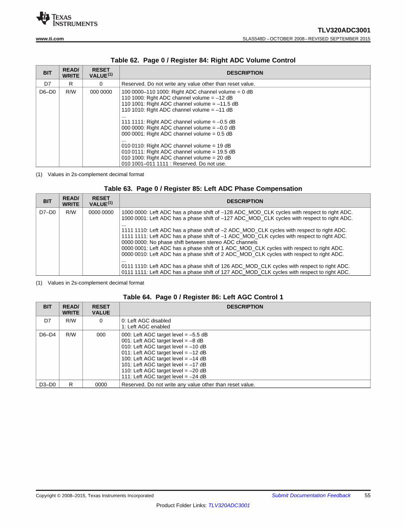
TLV320ADC3001www.ti.com SLAS548D –OCTOBER 2008–REVISED SEPTEMBER 2015
Table 62. Page 0 / Register 84: Right ADC Volume ControlREAD/ RESETBIT DESCRIPTIONWRITE VALUE (1)
D7 R 0 Reserved. Do not write any value other than reset value.D6–D0 R/W 000 0000 100 0000–110 1000: Right ADC channel volume = 0 dB
110 1000: Rght ADC channel volume = –12 dB110 1001: Right ADC channel volume = –11.5 dB110 1010: Rght ADC channel volume = –11 dB...111 1111: Right ADC channel volume = –0.5 dB000 0000: Right ADC channel volume = –0.0 dB000 0001: Right ADC channel volume = 0.5 dB...010 0110: Right ADC channel volume = 19 dB010 0111: Right ADC channel volume = 19.5 dB010 1000: Right ADC channel volume = 20 dB010 1001–011 1111 : Reserved. Do not use.
(1) Values in 2s-complement decimal format
Table 63. Page 0 / Register 85: Left ADC Phase CompensationREAD/ RESETBIT DESCRIPTIONWRITE VALUE (1)
D7–D0 R/W 0000 0000 1000 0000: Left ADC has a phase shift of –128 ADC_MOD_CLK cycles with respect to right ADC.1000 0001: Left ADC has a phase shift of –127 ADC_MOD_CLK cycles with respect to right ADC....1111 1110: Left ADC has a phase shift of –2 ADC_MOD_CLK cycles with respect to right ADC.1111 1111: Left ADC has a phase shift of –1 ADC_MOD_CLK cycles with respect to right ADC.0000 0000: No phase shift between stereo ADC channels0000 0001: Left ADC has a phase shift of 1 ADC_MOD_CLK cycles with respect to right ADC.0000 0010: Left ADC has a phase shift of 2 ADC_MOD_CLK cycles with respect to right ADC....0111 1110: Left ADC has a phase shift of 126 ADC_MOD_CLK cycles with respect to right ADC.0111 1111: Left ADC has a phase shift of 127 ADC_MOD_CLK cycles with respect to right ADC.
(1) Values in 2s-complement decimal format
Table 64. Page 0 / Register 86: Left AGC Control 1BIT READ/ RESET DESCRIPTION
WRITE VALUED7 R/W 0 0: Left AGC disabled
1: Left AGC enabledD6–D4 R/W 000 000: Left AGC target level = –5.5 dB
001: Left AGC target level = –8 dB010: Left AGC target level = –10 dB011: Left AGC target level = –12 dB100: Left AGC target level = –14 dB101: Left AGC target level = –17 dB110: Left AGC target level = –20 dB111: Left AGC target level = –24 dB
D3–D0 R 0000 Reserved. Do not write any value other than reset value.
Copyright © 2008–2015, Texas Instruments Incorporated Submit Documentation Feedback 55
Product Folder Links: TLV320ADC3001

TLV320ADC3001SLAS548D –OCTOBER 2008–REVISED SEPTEMBER 2015 www.ti.com
Table 65. Page 0 / Register 87: Left AGC Control 2READ/ RESETBIT DESCRIPTIONWRITE VALUE
D7–D6 R/W 00 00: Left AGC hysteresis setting of 1 dB01: Left AGC hysteresis setting of 2 dB10: Left AGC hysteresis setting of 4 dB11: Left AGC hysteresis disabled
D5–D1 R/W 00 000 00 000: Left AGC noise/silence detection is disabled.00 001: Left AGC noise threshold = –30 dB00 010: Left AGC noise threshold = –32 dB00 011: Left AGC noise threshold = –34 dB...11 101: Left AGC noise threshold = –86 dB11 110: Left AGC noise threshold = –88 dB11 111: Left AGC noise threshold = –90 dB
D0 R/W 0 0: Disable clip stepping for AGC1: Enable clip stepping for AGC
Table 66. Page 0 / Register 88: Left AGC Maximum GainREAD/ RESETBIT DESCRIPTIONWRITE VALUE
D7 R 0 Reserved. Do not write any value other than reset value.D6–D0 R/W 111 1111 000 0000: Left AGC maximum gain = 0 dB
000 0001: Left AGC maximum gain = 0.5 dB000 0010: Left AGC maximum gain = 1 dB...101 0000: Left AGC maximum gain = 40 dB101 0001–111 1111: Reserved. Do not use.
Table 67. Page 0 / Register 89: Left AGC Attack TimeBIT READ/ RESET DESCRIPTION
WRITE VALUED7–D3 R/W 0000 0 0000 0: Left AGC attack time = 1 × (32/fS)
0000 1: Left AGC attack time = 3 × (32/fS)0001 0: Left AGC attack time = 5 × (32/fS)0001 1: Left AGC attack time = 7 × (32/fS)0010 0: Left AGC attack time = 9 × (32/fS)...1111 0: Left AGC attack time = 61 × (32/fS)1111 1: Left AGC attack time = 63 × (32/fS)
D2–D0 R/W 000 000: Multiply factor for the programmed left AGC attack time = 1001: Multiply factor for the programmed left AGC attack time = 2010: Multiply factor for the programmed left AGC attack time = 4...111: Multiply factor for the programmed left AGC attack time = 128
Table 68. Page 0 / Register 90: Left AGC Decay TimeREAD/ RESETBIT DESCRIPTIONWRITE VALUE
D7–D3 R/W 0000 0 0000 0: Left AGC decay time = 1 × (512/fS)0000 1: Left AGC decay time = 3 × (512/fS)0001 0: Left AGC decay time = 5 × (512/fS)0001 1: Left AGC decay time = 7 × (512/fS)0010 0: Left AGC decay time = 9 × (512/fS)...1111 0: Left AGC decay time = 61 × (512/fS)1111 1: Left AGC decay time = 63 × (512/fS)
D2–D0 R/W 000 000: Multiply factor for the programmed left AGC decay time = 1001: Multiply factor for the programmed left AGC decay time = 2010: Multiply factor for the programmed left AGC decay time = 4...111: Multiply factor for the programmed left AGC decay time = 128
56 Submit Documentation Feedback Copyright © 2008–2015, Texas Instruments Incorporated
Product Folder Links: TLV320ADC3001

TLV320ADC3001www.ti.com SLAS548D –OCTOBER 2008–REVISED SEPTEMBER 2015
Table 69. Page 0 / Register 91: Left AGC Noise DebounceBIT READ/ RESET DESCRIPTION
WRITE VALUED7–D5 R 000 Reserved. Do not write any value other than reset value.D4–D0 R/W 0 0000 0 0000: Left AGC noise debounce = 0/fS
0 0001: Left AGC noise debounce = 4/fS0 0010: Left AGC noise debounce = 8/fS0 0011: Left AGC noise debounce = 16/fS0 0100: Left AGC noise debounce = 32/fS0 0101: Left AGC noise debounce = 64/fS0 0110: Left AGC noise debounce = 128/fS0 0111: Left AGC noise debounce = 256/fS0 1000: Left AGC noise debounce = 512/fS0 1001: Left AGC noise debounce = 1024/fS0 1010: Left AGC noise debounce = 2048/fS0 1011: Left AGC noise debounce = 4096/fS0 1100: Left AGC noise debounce = 2 × 4096/fS0 1101: Left AGC noise debounce = 3 × 4096/fS0 1110: Left AGC noise debounce = 4 × 4096/fS...1 1110: Left AGC noise debounce = 20 × 4096/fS1 1111: Left AGC noise debounce = 21 × 4096/fS
Table 70. Page 0 / Register 92: Left AGC Signal DebounceREAD/ RESETBIT DESCRIPTIONWRITE VALUE
D7–D4 R 0000 Reserved. Do not write any value other than reset value.D3–D0 R/W 0000 0000: Left AGC signal debounce = 0/fS
0001: Left AGC signal debounce = 4/fS0010: Left AGC signal debounce = 8/fS0011: Left AGC signal debounce = 16/fS0100: Left AGC signal debounce = 32/fS0101: Left AGC signal debounce = 64/fS0110: Left AGC signal debounce = 128/fS0111: Left AGC signal debounce = 256/fS1000: Left AGC signal debounce = 512/fS1001: Left AGC signal debounce = 1024/fS1010: Left AGC signal debounce = 2048/fS1011: Left AGC signal debounce = 2 × 2048/fS1100: Left AGC signal debounce = 3 × 2048/fS1101: Left AGC signal debounce = 4 × 2048/fS1110: Left AGC signal debounce = 5 × 2048/fS1111: Left AGC signal debounce = 6 × 2048/fS
Table 71. Page 0 / Register 93: Left AGC Gain AppliedREAD/ RESETBIT (1) DESCRIPTIONWRITE VALUE
D7–D0 R 0000 0000 Left AGC Gain Value Status:1110 1000: Gain applied by left AGC = –12 dB1110 1001: Gain applied by left AGC = –11.5 dB...1111 1111: Gain applied by left AGC = –0.5 dB0000 0000: Gain applied by left AGC = 0 dB0000 0001: Gain applied by left AGC = 0.5 dB...0100 1111: Gain applied by left AGC = 39.5 dB0101 0000: Gain applied by left AGC = 40 dB0101 0001–1111 1111: Reserved. Do not use.
(1) These are read-only bits.
Copyright © 2008–2015, Texas Instruments Incorporated Submit Documentation Feedback 57
Product Folder Links: TLV320ADC3001

TLV320ADC3001SLAS548D –OCTOBER 2008–REVISED SEPTEMBER 2015 www.ti.com
Table 72. Page 0 / Register 94: Right AGC Control 1READ/ RESETBIT DESCRIPTIONWRITE VALUE
D7 R/W 0 0: Right AGC disabled1: Right AGC enabled
D6–D4 R/W 000 000: Right AGC target level = –5.5 dB000: Right AGC target level = –8 dB001: Right AGC target level = –10 dB010: Right AGC target level = –12 dB011: Right AGC target level = –14 dB100: Right AGC target level = –17 dB101: Right AGC target level = –20 dB111: Right AGC target level = –24 dB
D3–D0 R 0000 Reserved. Do not write any value other than reset value.
Table 73. Page 0 / Register 95: Right AGC Control 2READ/ RESETBIT DESCRIPTIONWRITE VALUE
D7–D6 R/W 00 00: Right AGC hysteresis setting of 1 dB01: Right AGC hysteresis setting of 2 dB10: Right AGC hysteresis setting of 4 dB11: Right AGC hysteresis disabled.
D5–D1 R/W 00 000 00 000: Right AGC noise/silence detection is disabled.00 001: Right AGC noise threshold = –30 dB00 010: Right AGC noise threshold = –32 dB00 011: Right AGC noise threshold = –34 dB...11 101: Right AGC noise threshold = –86 dB11 110: Right AGC noise threshold = –88 dB11 111: Right AGC noise threshold = –90 dB
D0 R/W 0 0: Disable clip stepping for right AGC.1: Enable clip stepping for right AGC.
Table 74. Page 0 / Register 96: Right AGC Maximum GainREAD/ RESETBIT DESCRIPTIONWRITE VALUE
D7 R 0 Reserved. Do not write any value other than reset value.D6–D0 R/W 111 1111 000 0000: Right AGC maximum gain = 0 dB
000 0001: Right AGC maximum gain = 0.5 dB000 0010: Right AGC maximum gain = 1 dB...101 0000: Right AGC maximum gain = 40 dB101 0001–111 1111: Not Used.
Table 75. Page 0 / Register 97: Right AGC Attack TimeREAD/ RESETBIT DESCRIPTIONWRITE VALUE
D7–D3 R/W 0000 0 0000 0: Right AGC attack time = 1 × (32/fS)0000 1: Right AGC attack time = 3 × (32/fS)0001 0: Right AGC attack time = 5 × (32/fS)0001 1: Right AGC attack time = 7 × (32/fS)0010 0: Right AGC attack time = 9 × (32/fS)...1111 0: Right AGC attack time = 61 × (32/fS)1111 1: Right AGC attack time = 63 × (32/fS)
D2–D0 R/W 000 000: Multiplication factor for the programmed right AGC attack time = 1001: Multiplication factor for the programmed right AGC attack time = 2010: Multiplication factor for the programmed right AGC attack time = 4...111: Multiplication factor for the programmed right AGC attack time = 128
58 Submit Documentation Feedback Copyright © 2008–2015, Texas Instruments Incorporated
Product Folder Links: TLV320ADC3001
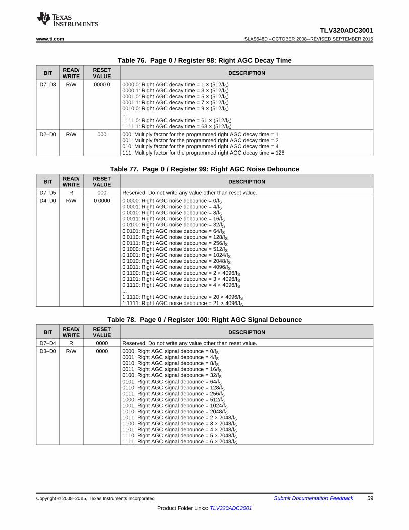
TLV320ADC3001www.ti.com SLAS548D –OCTOBER 2008–REVISED SEPTEMBER 2015
Table 76. Page 0 / Register 98: Right AGC Decay TimeREAD/ RESETBIT DESCRIPTIONWRITE VALUE
D7–D3 R/W 0000 0 0000 0: Right AGC decay time = 1 × (512/fS)0000 1: Right AGC decay time = 3 × (512/fS)0001 0: Right AGC decay time = 5 × (512/fS)0001 1: Right AGC decay time = 7 × (512/fS)0010 0: Right AGC decay time = 9 × (512/fS)...1111 0: Right AGC decay time = 61 × (512/fS)1111 1: Right AGC decay time = 63 × (512/fS)
D2–D0 R/W 000 000: Multiply factor for the programmed right AGC decay time = 1001: Multiply factor for the programmed right AGC decay time = 2010: Multiply factor for the programmed right AGC decay time = 4111: Multiply factor for the programmed right AGC decay time = 128
Table 77. Page 0 / Register 99: Right AGC Noise DebounceREAD/ RESETBIT DESCRIPTIONWRITE VALUE
D7–D5 R 000 Reserved. Do not write any value other than reset value.D4–D0 R/W 0 0000 0 0000: Right AGC noise debounce = 0/fS
0 0001: Right AGC noise debounce = 4/fS0 0010: Right AGC noise debounce = 8/fS0 0011: Right AGC noise debounce = 16/fS0 0100: Right AGC noise debounce = 32/fS0 0101: Right AGC noise debounce = 64/fS0 0110: Right AGC noise debounce = 128/fS0 0111: Right AGC noise debounce = 256/fS0 1000: Right AGC noise debounce = 512/fS0 1001: Right AGC noise debounce = 1024/fS0 1010: Right AGC noise debounce = 2048/fS0 1011: Right AGC noise debounce = 4096/fS0 1100: Right AGC noise debounce = 2 × 4096/fS0 1101: Right AGC noise debounce = 3 × 4096/fS0 1110: Right AGC noise debounce = 4 × 4096/fS...1 1110: Right AGC noise debounce = 20 × 4096/fS1 1111: Right AGC noise debounce = 21 × 4096/fS
Table 78. Page 0 / Register 100: Right AGC Signal DebounceREAD/ RESETBIT DESCRIPTIONWRITE VALUE
D7–D4 R 0000 Reserved. Do not write any value other than reset value.D3–D0 R/W 0000 0000: Right AGC signal debounce = 0/fS
0001: Right AGC signal debounce = 4/fS0010: Right AGC signal debounce = 8/fS0011: Right AGC signal debounce = 16/fS0100: Right AGC signal debounce = 32/fS0101: Right AGC signal debounce = 64/fS0110: Right AGC signal debounce = 128/fS0111: Right AGC signal debounce = 256/fS1000: Right AGC signal debounce = 512/fS1001: Right AGC signal debounce = 1024/fS1010: Right AGC signal debounce = 2048/fS1011: Right AGC signal debounce = 2 × 2048/fS1100: Right AGC signal debounce = 3 × 2048/fS1101: Right AGC signal debounce = 4 × 2048/fS1110: Right AGC signal debounce = 5 × 2048/fS1111: Right AGC signal debounce = 6 × 2048/fS
Copyright © 2008–2015, Texas Instruments Incorporated Submit Documentation Feedback 59
Product Folder Links: TLV320ADC3001

TLV320ADC3001SLAS548D –OCTOBER 2008–REVISED SEPTEMBER 2015 www.ti.com
Table 79. Page 0 / Register 101: Right AGC Gain AppliedBIT (1) READ/ RESET DESCRIPTION
WRITE VALUED7–D0 R 0000 0000 Right AGC Gain Value Status:
1110 1000: Gain applied by right AGC = –12 dB1110 1001: Gain applied by right AGC = –11.5 dB...1111 1111: Gain applied by right AGC = –0.5 dB0000 0000: Gain applied by right AGC = 0 dB0000 0001: Gain applied by right AGC = 0.5 dB...0100 1111: Gain applied by right AGC = 39.5 dB0101 0000: Gain applied by right AGC = 40 dB0101 0001–1111 1111: Reserved. Do not use.
(1) These are read-only bits.
Table 80. Page 0 / Register 102 Through Page 0 / Register 127: ReservedBIT READ/ RESET DESCRIPTION
WRITE VALUED7–D0 R XXXX XXXX Reserved. Do not write to these registers.
10.6.3 CONTROL REGISTERS Page 1: ADC Routing, PGA, Power-Controls, Etc.
Table 81. Page 1 / Register 0: Page Control Register (1)
READ/ RESETBIT DESCRIPTIONWRITE VALUED7–D0 R/W 0000 0000 0000 0000: Page 0 selected
0000 0001: Page 1 selected...1111 1110: Page 254 selected (reserved)1111 1111: Page 255 selected (reserved)
(1) Valid pages are 0, 1, 4, 5, 32–47. All other pages are reserved (do not access).
Table 82. Page 1 / Register 1 Through Page 1 / Register 25: ReservedBIT READ/ RESET DESCRIPTION
WRITE VALUED7–D0 R XXXX XXXX Reserved. Do not write to these registers.
60 Submit Documentation Feedback Copyright © 2008–2015, Texas Instruments Incorporated
Product Folder Links: TLV320ADC3001

TLV320ADC3001www.ti.com SLAS548D –OCTOBER 2008–REVISED SEPTEMBER 2015
Table 83. Page 1 / Register 26: Dither ControlREAD/ RESETBIT DESCRIPTIONWRITE VALUE
D7–D4 R/W 0000 DC Offset Into Input of Left ADC; Signed Magnitude Number in ±15-mV Steps1111: –105 mV...1011: –45 mV1010: –30 mV1001: –15 mV0000: 0 mV0001: 15 mV0010: 30 mV0011: 45 mV...0111: 105 mV
D3–D0 R/W 0000 DC Offset Into Input of Right ADC; Signed Magnitude Number in ±15-mV Steps1111: –105 mV...1011: –45 mV1010: –30 mV1001: –15 mV0000: 0 mV0001: 15 mV0010: 30 mV0011: 45 mV...0111: 105 mV
Table 84. Page 1 / Register 27 Through Page 1 / Register 50: ReservedBIT READ/ RESET DESCRIPTION
WRITE VALUED7–D0 R XXXX XXXX Reserved. Do not write to these registers.
Table 85. Page 1 / Register 51: MICBIAS ControlREAD/ RESETBIT DESCRIPTIONWRITE VALUE
D7–D5 R 000 Reserved. Do not write any value other than reset value.D4–D3 R/W 00 00: MICBIAS2 is powered down.
01: MICBIAS2 is powered to 2 V.10: MICBIAS2 is powered to 2.5 V.11: MICBIAS2 is connected to AVDD.
D2–D0 R 000 Reserved. Do not write any value other than reset value.
Table 86. Page 1 / Register 52: Left ADC Input Selection for Left PGAREAD/ RESETBIT DESCRIPTIONWRITE VALUE
D7–D4 R/W 1111 Reserved. Do not write any value other than reset value.D3–D2 R/W 11 IN2L Pin (Single-Ended) (1)
00: 0-dB setting is chosen.01: –6-dB setting is chosen.10: Is not connected to the left ADC PGA11: Is not connected to the left ADC PGA
D1–D0 R/W 11 IN1l(P) Pin (Single-Ended) (1)
00: 0-dB setting is chosen.01: –6-dB setting is chosen.10: Is not connected to the left ADC PGA11: Is not connected to the left ADC PGA
(1) To maintain the same PGA output level for both single-ended and differential pairs, the single-ended inputs have a 2× gain applied.
Copyright © 2008–2015, Texas Instruments Incorporated Submit Documentation Feedback 61
Product Folder Links: TLV320ADC3001

TLV320ADC3001SLAS548D –OCTOBER 2008–REVISED SEPTEMBER 2015 www.ti.com
Table 87. Page 1 / Register 53: ReservedREAD/ RESETBIT DESCRIPTIONWRITE VALUE
D7–D0 R XXXX XXXX Reserved. Do not write to this register.
Table 88. Page 1 / Register 54: Left ADC Input Selection for Left PGAREAD/ RESETBIT DESCRIPTIONWRITE VALUE
D7 R/W 0 Reserved. Do not write any value other than reset value.D6 R/W 0 Left ADC Common-Mode Select
0: Left ADC channel unselected inputs are not biased weakly to the ADC common-mode voltage.1: Left ADC channel unselected inputs are biased weakly to the ADC common-mode voltage.
D5–D4 R/W 11 Differential Pair [Plus = IN1L(P) and Minus = IN1R(M)]00: 0-dB setting is chosen.01: –6-dB setting is chosen.10–11: Not connected to the left ADC PGA
D3–D2 R/W 11 Reserved. Do not write any value other than reset value.D1–D0 R/W 11 IN1R(M) Pin (Single-Ended) (1)
00: 0 dB setting is chosen.01: –6 dB setting is chosen.10–11: Not connected to the left ADC PGA.
(1) To maintain the same PGA output level for both single-ended and differential pairs, the single-ended inputs have a 2× gain applied.
Table 89. Page 1 / Register 55: Right ADC Input selection for Right PGAREAD/ RESETBIT DESCRIPTIONWRITE VALUE
D7–D2 R/W 11 Reserved. Do not write any value other than reset value.D1–D0 R/W 11 IN1R(M) Pin (Single-Ended) (1)
00: 0-dB setting is chosen.01: –6-dB setting is chosen.10–11: Not connected to the right ADC PGA.
(1) To maintain the same PGA output level for both single-ended and differential pairs, the single-ended inputs have a 2× gain applied.
Table 90. Page 1 / Register 56: ReservedREAD/ RESETBIT DESCRIPTIONWRITE VALUE
D7–D0 R XXXX XXXX Reserved. Do not write to this register.
Table 91. Page 1 / Register 57: Right ADC Input Selection for Right PGAREAD/ RESETBIT DESCRIPTIONWRITE VALUE
D7 R/W 0 Reserved. Do not write any value other than reset value.D6 R/W 0 Right ADC Common-Mode Select
0: Right ADC channel unselected inputs are not biased weakly to the ADC common-mode voltage.1: Right ADC channel unselected inputs are biased weakly to the ADC common-mode voltage.
D5–D4 R/W 11 Differential Pair [Plus = IN1L(P) and Minus = IN1R(M)]00: 0-dB setting is chosen.01: –6 dB setting is chosen.10–11: Not connected to the right ADC PGA
D3–D2 R/W 11 Reserved. Do not write any value other than reset value.D1–D0 R/W 11 IN1L(P) Pin (Single-Ended) (1)
00: 0-dB setting is chosen.01: –6-dB setting is chosen.10–11: Not connected to the right ADC PGA
(1) To maintain the same PGA output level for both single-ended and differential pairs, the single-ended inputs have a 2× gain applied.
62 Submit Documentation Feedback Copyright © 2008–2015, Texas Instruments Incorporated
Product Folder Links: TLV320ADC3001

TLV320ADC3001www.ti.com SLAS548D –OCTOBER 2008–REVISED SEPTEMBER 2015
Table 92. Page 1 / Register 58: ReservedBIT READ/ RESET DESCRIPTION
WRITE VALUED7–D0 R XXXX XXXX Reserved. Do not write to this register.
Table 93. Page 1 / Register 59: Left Analog PGA SettingsREAD/ RESETBIT DESCRIPTIONWRITE VALUE
D7 R/W 1 0: Left PGA is not muted.1: Left PGA is muted.
D6–D0 R/W 000 0000 000 0000: Left PGA gain = 0 dB000 0001: Left PGA gain = 0.5 dB000 0010: Left PGA gain = 1 dB...101 0000: Left PGA gain = 40 dB101 0001–111 1111: Reserved. Do not use.
Table 94. Page 1 / Register 60: Right Analog PGA SettingsREAD/ RESETBIT DESCRIPTIONWRITE VALUE
D7 R/W 1 0: Right PGA is not muted1: Right PGA is muted
D6–D0 R/W 000 0000 000 0000: Right PGA gain = 0 dB000 0001: Right PGA gain = 0.5 dB000 010: Right PGA gain = 1 dB...101 0000: Right PGA gain = 40 dB101 0001–111 1111: Reserved. Do not use.
Table 95. Page 1 / Register 61: ADC Low-Current ModesREAD/ RESETBIT DESCRIPTIONWRITE VALUE
D7–D1 R 0000 000 Reserved. Write only zeros to these bits.D0 R/W 0 0: 1× ADC modulator current used
1: 0.5× ADC modulator current used
Table 96. Page 1 / Register 62: ADC Analog PGA FlagsBIT READ/ RESET DESCRIPTION
WRITE VALUED7–D2 R 0000 00 Reserved. Do not write any value other than reset value.
D1 R 0 0: Left ADC PGA, applied gain ≠ programmed gain1: Left ADC PGA, applied gain = programmed gain
D0 R 0 0: Right ADC PGA, applied gain ≠ programmed gain1: Right ADC PGA, applied gain = programmed gain
Table 97. Page 1 / Register 63 Through Page 1 / Register 127: ReservedREAD/ RESETBIT DESCRIPTIONWRITE VALUE
D7–D0 R XXXX XXXX Reserved. Do not write to these registers.
Copyright © 2008–2015, Texas Instruments Incorporated Submit Documentation Feedback 63
Product Folder Links: TLV320ADC3001

TLV320ADC3001SLAS548D –OCTOBER 2008–REVISED SEPTEMBER 2015 www.ti.com
10.6.4 Control Registers, Page 4: ADC Digital Filter CoefficientsDefault values shown for this page only become valid 100 μs following a hardware or software reset.
Table 98. Page 4 / Register 0: Page Control Register (1)
READ/ RESETBIT DESCRIPTIONWRITE VALUED7–D0 R/W 0000 0000 0000 0000: Page 0 selected
0000 0001: Page 1 selected...1111 1110: Page 254 selected (reserved)1111 1111: Page 255 selected (reserved)
(1) Valid pages are 0, 1, 4, 5, 32–47. All other pages are reserved (do not access).
The remaining page-4 registers are either reserved registers or are used for setting coefficients for the variousfilters in the processing blocks. Reserved registers must not be written to.
The filter coefficient registers are arranged in pairs, with two adjacent 8-bit registers containing the 16-bitcoefficient for a single filter. The 16-bit integer contained in the MSB and LSB registers for a coefficient areinterpreted as a 2s-complement integer, with possible values ranging from –32,768 to 32,767. Whenprogramming any coefficient value for a filter, the MSB register must always be written first, immediately followedby the LSB register. Even if only the MSB or LSB portion of the coefficient changes, both registers must bewritten in this sequence. Table 99 is a list of the page-4 registers, excepting the previously described register 0.
Table 99. Page-4 RegistersREGISTER RESET VALUE REGISTER NAMENUMBER
1 XXXX XXXX Reserved. Do not write to this register.Coefficient N0(15:8) for AGC LPF (first-order IIR) used as averager to detect level or coefficient2 0000 0001 C1(15:8) of ADC miniDSPCoefficient N0(7:0) for AGC LPF (first-order IIR) used as averager to detect level or coefficient3 0001 0111 C1(7:0) of ADC miniDSPCoefficient N1(15:8) for AGC LPF (first-order IIR) used as averager to detect level or coefficient4 0000 0001 C2(15:8) of ADC miniDSPCoefficient N1(7:0) for AGC LPF (first-order IIR) used as averager to detect level or coefficient5 0001 0111 C2(7:0) of ADC miniDSPCoefficient D1(15:8) for AGC LPF (first-order IIR) used as averager to detect level or coefficient6 0111 1101 C3(15:8) of ADC miniDSPCoefficient D1(7:0) for AGC LPF (first-order IIR) used as averager to detect level or coefficient7 1101 0011 C3(7:0) of ADC miniDSPCoefficient N0(15:8) for left ADC programmable first-order IIR or coefficient C4(15:8) of ADC8 0111 1111 miniDSP
9 1111 1111 Coefficient N0(7:0) for left ADC programmable first-order IIR or coefficient C4(7:0) of ADC miniDSPCoefficient N1(15:8) for left ADC programmable first-order IIR or coefficient C5(15:8) of ADC10 0000 0000 miniDSP
11 0000 0000 Coefficient N1(7:0) for left ADC programmable first-order IIR or coefficient C5(7:0) of ADC miniDSPCoefficient D1(15:8) for left ADC programmable first-order IIR or coefficient C6(15:8) of ADC12 0000 0000 miniDSP
13 0000 0000 Coefficient D1(7:0) for left ADC programmable first-order IIR or coefficient C6(7:0) of ADC miniDSPCoefficient N0(15:8) for left ADC biquad A or coefficient FIR0(15:8) for ADC FIR filter or coefficient14 0111 1111 C7(15:8) of ADC miniDSPCoefficient N0(7:0) for left ADC biquad A or coefficient FIR0(7:0) for ADC FIR filter or coefficient15 1111 1111 C7(7:0) of ADC miniDSPCoefficient N1(15:8) for left ADC biquad A or coefficient FIR1(15:8) for ADC FIR filter or coefficient16 0000 0000 C8(15:8) of ADC miniDSPCoefficient N1(7:0) for left ADC biquad A or coefficient FIR1(7:0) for ADC FIR filter or coefficient17 0000 0000 C8(7:0) of ADC miniDSPCoefficient N2(15:8) for left ADC biquad A or coefficient FIR2(15:8) for ADC FIR filter or coefficient18 0000 0000 C9(15:8) of ADC miniDSP
64 Submit Documentation Feedback Copyright © 2008–2015, Texas Instruments Incorporated
Product Folder Links: TLV320ADC3001

TLV320ADC3001www.ti.com SLAS548D –OCTOBER 2008–REVISED SEPTEMBER 2015
Table 99. Page-4 Registers (continued)REGISTER RESET VALUE REGISTER NAMENUMBER
Coefficient N2(7:0) for left ADC biquad A or coefficient FIR2(7:0) for ADC FIR filter or coefficient19 0000 0000 C9(7:0) of ADC miniDSPCoefficient D1(15:8) for left ADC biquad A or coefficient FIR3(15:8) for ADC FIR filter or coefficient20 0000 0000 C10(15:8) of ADC miniDSPCoefficient D1(7:0) for left ADC biquad A or coefficient FIR3(7:0) for ADC FIR filter or coefficient21 0000 0000 C10(7:0) of ADC miniDSPCoefficient D2(15:8) for left ADC biquad A or coefficient FIR4(15:8) for ADC FIR filter or coefficient22 0000 0000 C11(15:8) of ADC miniDSPCoefficient D2(7:0) for left ADC biquad A or coefficient FIR4(7:0) for ADC FIR filter or coefficient23 0000 0000 C11(7:0) of ADC miniDSPCoefficient N0(15:8) for left ADC biquad B or coefficient FIR5(15:8) for ADC FIR filter or coefficient24 0111 1111 C12(15:8) of ADC miniDSPCoefficient N0(7:0) for left ADC biquad B or coefficient FIR5(7:0) for ADC FIR filter or coefficient25 1111 1111 C12(7:0) of ADC miniDSPCoefficient N1(15:8) for left ADC biquad B or coefficient FIR6(15:8) for ADC FIR filter or coefficient26 0000 0000 C13(15:8) of ADC miniDSPCoefficient N1(7:0) for left ADC biquad B or coefficient FIR6(7:0) for ADC FIR filter or coefficient27 0000 0000 C13(7:0) of ADC miniDSPCoefficient N2(15:8) for left ADC biquad B or coefficient FIR7(15:8) for ADC FIR filter or coefficient28 0000 0000 C14(15:8) of ADC miniDSPCoefficient N2(7:0) for left ADC biquad B or coefficient FIR7(7:0) for ADC FIR filter or coefficient29 0000 0000 C14(7:0) of ADC miniDSPCoefficient D1(15:8) for left ADC biquad B or coefficient FIR8(15:8) for ADC FIR filter or coefficient30 0000 0000 C15(15:8) of ADC miniDSPCoefficient D1(7:0) for left ADC biquad B or coefficient FIR8(7:0) for ADC FIR filter or coefficient31 0000 0000 C15(7:0) of ADC miniDSPCoefficient D2(15:8) for left ADC biquad B or coefficient FIR9(15:8) for ADC FIR filter or coefficient32 0000 0000 C16(15:8) of ADC miniDSPCoefficient D2(7:0) for left ADC biquad B or coefficient FIR9(7:0) for ADC FIR filter or coefficient33 0000 0000 C16(7:0) of ADC miniDSPCoefficient N0(15:8) for left ADC biquad C or coefficient FIR10(15:8) for ADC FIR filter or coefficient34 0111 1111 C17(15:8) of ADC miniDSPCoefficient N0(7:0) for left ADC biquad C or coefficient FIR10(7:0) for ADC FIR filter or coefficient35 1111 1111 C17(7:0) of ADC miniDSPCoefficient N1(15:8) for left ADC biquad C or coefficient FIR11(15:8) for ADC FIR filter or coefficient36 0000 0000 C18(15:8) of ADC miniDSPCoefficient N1(7:0) for left ADC biquad C or coefficient FIR11(7:0) for ADC FIR filter or coefficient37 0000 0000 C18(7:0) of ADC miniDSPCoefficient N2(15:8) for left ADC biquad C or coefficient FIR12(15:8) for ADC FIR filter or coefficient38 0000 0000 C19(15:8) of ADC miniDSPCoefficient N2(7:0) for left ADC biquad C or coefficient FIR12(7:0) for ADC FIR filter or coefficient39 0000 0000 C19(7:0) of ADC miniDSPCoefficient D1(15:8) for left ADC biquad C or coefficient FIR13(15:8) for ADC FIR filter or coefficient40 0000 0000 C20(15:8) of ADC miniDSPCoefficient D1(7:0) for left ADC biquad C or coefficient FIR13(7:0) for ADC FIR filter or coefficient41 0000 0000 C20(7:0) of ADC miniDSPCoefficient D2(15:8) for left ADC biquad C or coefficient FIR14(15:8) for ADC FIR filter or coefficient42 0000 0000 C21(15:8) of ADC miniDSPCoefficient D2(7:0) for left ADC biquad C or coefficient FIR14(7:0) for ADC FIR filter or coefficient43 0000 0000 C21(7:0) of ADC miniDSPCoefficient N0(15:8) for left ADC biquad D or coefficient FIR15(15:8) for ADC FIR filter or coefficient44 0111 1111 C22(15:8) of ADC miniDSPCoefficient N0(7:0) for left ADC biquad D or coefficient FIR15(7:0) for ADC FIR filter or coefficient45 1111 1111 C22(7:0) of ADC miniDSP
Copyright © 2008–2015, Texas Instruments Incorporated Submit Documentation Feedback 65
Product Folder Links: TLV320ADC3001

TLV320ADC3001SLAS548D –OCTOBER 2008–REVISED SEPTEMBER 2015 www.ti.com
Table 99. Page-4 Registers (continued)REGISTER RESET VALUE REGISTER NAMENUMBER
Coefficient N1(15:8) for left ADC biquad D or coefficient FIR16(15:8) for ADC FIR filter or coefficient46 0000 0000 C23(15:8) of ADC miniDSPCoefficient N1(7:0) for left ADC biquad D or coefficient FIR16(7:0) for ADC FIR filter or coefficient47 0000 0000 C23(7:0) of ADC miniDSPCoefficient N2(15:8) for left ADC biquad D or coefficient FIR17(15:8) for ADC FIR filter or coefficient48 0000 0000 C24(15:8) of ADC miniDSPCoefficient N2(7:0) for left ADC biquad D or coefficient FIR17(7:0) for ADC FIR filter or coefficient49 0000 0000 C24(7:0) of ADC miniDSPCoefficient D1(15:8) for left ADC biquad D or coefficient FIR18(15:8) for ADC FIR filter or coefficient50 0000 0000 C25(15:8) of ADC miniDSPCoefficient D1(7:0) for left ADC biquad D or coefficient FIR18(7:0) for ADC FIR filter or coefficient51 0000 0000 C25(7:0) of ADC miniDSPCoefficient D2(15:8) for left ADC biquad D or coefficient FIR19(15:8) for ADC FIR filter or coefficient52 0000 0000 C26(15:8) of ADC miniDSPCoefficient D2(7:0) for left ADC biquad D or coefficient FIR19(7:0) for ADC FIR filter or coefficient53 0000 0000 C26(7:0) of ADC miniDSPCoefficient N0(15:8) for left ADC biquad E or coefficient FIR20(15:8) for ADC FIR filter or coefficient54 0111 1111 C27(15:8) of ADC miniDSPCoefficient N0(7:0) for left ADC biquad E or coefficient FIR20(7:0) for ADC FIR filter or coefficient55 1111 1111 C27(7:0) of ADC miniDSPCoefficient N1(15:8) for left ADC biquad E or coefficient FIR21(15:8) for ADC FIR filter or coefficient56 0000 0000 C28(15:8) of ADC miniDSPCoefficient N1(7:0) for left ADC biquad E or coefficient FIR21(7:0) for ADC FIR filter or coefficient57 0000 0000 C28(7:0) of ADC miniDSPCoefficient N2(15:8) for left ADC biquad E or coefficient FIR22(15:8) for ADC FIR filter or coefficient58 0000 0000 C29(15:8) of ADC miniDSPCoefficient N2(7:0) for left ADC biquad E or coefficient FIR22(7:0) for ADC FIR filter or coefficient59 0000 0000 C29(7:0) of ADC miniDSPCoefficient D1(15:8) for left ADC biquad E or coefficient FIR23(15:8) for ADC FIR filter or coefficient60 0000 0000 C30(15:8) of ADC miniDSPCoefficient D1(7:0) for left ADC biquad E or coefficient FIR23(7:0) for ADC FIR filter or coefficient61 0000 0000 C30(7:0) of ADC miniDSPCoefficient D2(15:8) for left ADC biquad E or coefficient FIR24(15:8) for ADC FIR filter or coefficient62 0000 0000 C31(15:8) of ADC miniDSPCoefficient D2(7:0) for left ADC biquad E or coefficient FIR24(7:0) for ADC FIR filter or coefficient63 0000 0000 C31(7:0) of ADC miniDSP
64 0000 0000 Coefficient C32(15:8) of ADC miniDSP65 0000 0000 Coefficient C32(7:0) of ADC miniDSP66 0000 0000 Coefficient C33(15:8) of ADC miniDSP67 0000 0000 Coefficient C33(7:0) of ADC miniDSP68 0000 0000 Coefficient C34(15:8) of ADC miniDSP69 0000 0000 Coefficient C34(7:0) of ADC miniDSP70 0000 0000 Coefficient C35(15:8) of ADC miniDSP71 0000 0000 Coefficient C35(7:0) of ADC miniDSP
Coefficient N0(15:8) for right ADC programmable first-order IIR or coefficient C36(15:8) of ADC72 0000 0000 miniDSPCoefficient N0(7:0) for right ADC programmable first-order IIR or coefficient C36(7:0) of ADC73 0000 0000 miniDSPCoefficient N1(15:8) for right ADC programmable first-order IIR or coefficient C37(15:8) of ADC74 0000 0000 miniDSPCoefficient N1(7:0) for right ADC programmable first-order IIR or coefficient C37(7:0) of ADC75 0000 0000 miniDSPCoefficient D1(15:8) for right ADC programmable first-order IIR or coefficient C38(15:8) of ADC76 0000 0000 miniDSP
66 Submit Documentation Feedback Copyright © 2008–2015, Texas Instruments Incorporated
Product Folder Links: TLV320ADC3001

TLV320ADC3001www.ti.com SLAS548D –OCTOBER 2008–REVISED SEPTEMBER 2015
Table 99. Page-4 Registers (continued)REGISTER RESET VALUE REGISTER NAMENUMBER
Coefficient D1(7:0) for right ADC programmable first-order IIR or coefficient C38(7:0) of ADC77 0000 0000 miniDSPCoefficient N0(15:8) for right ADC biquad A or coefficient FIR0(15:8) for ADC FIR filter or coefficient78 0000 0000 C39(15:8) of ADC miniDSPCoefficient N0(7:0) for right ADC biquad A or coefficient FIR0(7:0) for ADC FIR filter or coefficient79 0000 0000 C39(7:0) of ADC miniDSPCoefficient N1(15:8) for right ADC biquad A or coefficient FIR1(15:8) for ADC FIR filter or coefficient80 0000 0000 C40(15:8) of ADC miniDSPCoefficient N1(7:0) for right ADC biquad A or coefficient FIR1(7:0) for ADC FIR filter or coefficient81 0000 0000 C40(7:0) of ADC miniDSPCoefficient N2(15:8) for right ADC biquad A or coefficient FIR2(15:8) for ADC FIR filter or coefficient82 0000 0000 C41(15:8) of ADC miniDSPCoefficient N2(7:0) for right ADC biquad A or coefficient FIR2(7:0) for ADC FIR filter or coefficient83 0000 0000 C41(7:0) of ADC miniDSPCoefficient D1(15:8) for right ADC biquad A or coefficient FIR3(15:8) for ADC FIR filter or coefficient84 0000 0000 C42(15:8) of ADC miniDSPCoefficient D1(7:0) for right ADC biquad A or coefficient FIR3(7:0) for ADC FIR filter or coefficient85 0000 0000 C42(7:0) of ADC miniDSPCoefficient D2(15:8) for right ADC biquad A or coefficient FIR4(15:8) for ADC FIR filter or coefficient86 0000 0000 C43(15:8) of ADC miniDSPCoefficient D2(7:0) for right ADC biquad A or coefficient FIR4(7:0) for ADC FIR filter or coefficient87 0000 0000 C43(7:0) of ADC miniDSPCoefficient N0(15:8) for right ADC biquad B or coefficient FIR5(15:8) for ADC FIR filter or coefficient88 0000 0000 C44(15:8) of ADC miniDSPCoefficient N0(7:0) for right ADC biquad B or coefficient FIR5(7:0) for ADC FIR filter or coefficient89 0000 0000 C44(7:0) of ADC miniDSPCoefficient N1(15:8) for right ADC biquad B or coefficient FIR6(15:8) for ADC FIR filter or coefficient90 0000 0000 C45(15:8) of ADC miniDSPCoefficient N1(7:0) for right ADC biquad B or coefficient FIR6(7:0) for ADC FIR filter or coefficient91 0000 0000 C45(7:0) of ADC miniDSPCoefficient N2(15:8) for right ADC biquad B or coefficient FIR7(15:8) for ADC FIR filter or coefficient92 0000 0000 C46(15:8) of ADC miniDSPCoefficient N2(7:0) for right ADC biquad B or coefficient FIR7(7:0) for ADC FIR filter or coefficient93 0000 0000 C46(7:0) of ADC miniDSPCoefficient D1(15:8) for right ADC biquad B or coefficient FIR8(15:8) for ADC FIR filter or coefficient94 0000 0000 C47(15:8) of ADC miniDSPCoefficient D1(7:0) for right ADC biquad B or coefficient FIR8(7:0) for ADC FIR filter or coefficient95 0000 0000 C47(7:0) of ADC miniDSPCoefficient D2(15:8) for right ADC biquad B or coefficient FIR9(15:8) for ADC FIR filter or coefficient96 0000 0000 C48(15:8) of ADC miniDSPCoefficient D2(7:0) for right ADC biquad B or coefficient FIR9(7:0) for ADC FIR filter or coefficient97 0000 0000 C48(7:0) of ADC miniDSPCoefficient N0(15:8) for right ADC biquad C or coefficient FIR10(15:8) for ADC FIR filter or98 0000 0000 coefficient C49(15:8) of ADC miniDSPCoefficient N0(7:0) for right ADC biquad C or coefficient FIR10(7:0) for ADC FIR filter or coefficient99 0000 0000 C49(7:0) of ADC miniDSPCoefficient N1(15:8) for right ADC biquad C or coefficient FIR11(15:8) for ADC FIR filter or100 0000 0000 coefficient C50(15:8) of ADC miniDSPCoefficient N1(7:0) for right ADC biquad C or coefficient FIR11(7:0) for ADC FIR filter or coefficient101 0000 0000 C50(7:0) of ADC miniDSPCoefficient N2(15:8) for right ADC biquad C or coefficient FIR12(15:8) for ADC FIR filter or102 0000 0000 coefficient C51(15:8) of ADC miniDSPCoefficient N2(7:0) for right ADC biquad C or coefficient FIR12(7:0) for ADC FIR filter or coefficient103 0000 0000 C51(7:0) of ADC miniDSP
Copyright © 2008–2015, Texas Instruments Incorporated Submit Documentation Feedback 67
Product Folder Links: TLV320ADC3001

TLV320ADC3001SLAS548D –OCTOBER 2008–REVISED SEPTEMBER 2015 www.ti.com
Table 99. Page-4 Registers (continued)REGISTER RESET VALUE REGISTER NAMENUMBER
Coefficient D1(15:8) for right ADC biquad C or coefficient FIR13(15:8) for ADC FIR filter or104 0000 0000 coefficient C52(15:8) of ADC miniDSPCoefficient D1(7:0) for right ADC biquad C or coefficient FIR13(7:0) for ADC FIR filter or coefficient105 0000 0000 C52(7:0) of ADC miniDSPCoefficient D2(15:8) for right ADC biquad C or coefficient FIR14(15:8) for ADC FIR filter or106 0000 0000 coefficient C53(15:8) of ADC miniDSPCoefficient D2(7:0) for right ADC biquad C or coefficient FIR14(7:0) for ADC FIR filter or coefficient107 0000 0000 C53(7:0) of ADC miniDSPCoefficient N0(15:8) for right ADC biquad D or coefficient FIR15(15:8) for ADC FIR filter or108 0000 0000 coefficient C54(15:8) of ADC miniDSPCoefficient N0(7:0) for right ADC biquad D or coefficient FIR15(7:0) for ADC FIR filter or coefficient109 0000 0000 C54(7:0) of ADC miniDSPCoefficient N1(15:8) for right ADC biquad D or coefficient FIR16(15:8) for ADC FIR filter or110 0000 0000 coefficient C55(15:8) of ADC miniDSPCoefficient N1(7:0) for right ADC biquad D or coefficient FIR16(7:0) for ADC FIR filter or coefficient111 0000 0000 C55(7:0) of ADC miniDSPCoefficient N2(15:8) for right ADC biquad D or coefficient FIR17(15:8) for ADC FIR filter or112 0000 0000 coefficient C56(15:8) of ADC miniDSPCoefficient N2(7:0) for right ADC biquad D or coefficient FIR17(7:0) for ADC FIR filter or coefficient113 0000 0000 C56(7:0) of ADC miniDSPCoefficient D1(15:8) for right ADC biquad D or coefficient FIR18(15:8) for ADC FIR filter or114 0000 0000 coefficient C57(15:8) of ADC miniDSPCoefficient D1(7:0) for right ADC biquad D or coefficient FIR18(7:0) for ADC FIR filter or coefficient115 0000 0000 C57(7:0) of ADC miniDSPCoefficient D2(15:8) for right ADC biquad D or coefficient FIR19(15:8) for ADC FIR filter or116 0000 0000 coefficient C58(15:8) of ADC miniDSPCoefficient D2(7:0) for right ADC biquad D or coefficient FIR19(7:0) for ADC FIR filter or coefficient117 0000 0000 C58(7:0) of ADC miniDSPCoefficient N0(15:8) for right ADC biquad E or coefficient FIR20(15:8) for ADC FIR filter or118 0000 0000 coefficient C59(15:8) of ADC miniDSPCoefficient N0(7:0) for right ADC biquad E or coefficient FIR20(7:0) for ADC FIR filter or coefficient119 0000 0000 C59(7:0) of ADC miniDSPCoefficient N1(15:8) for right ADC biquad E or coefficient FIR21(15:8) for ADC FIR filter or120 0000 0000 coefficient C60(15:8) of ADC miniDSPCoefficient N1(7:0) for right ADC biquad E or coefficient FIR21(7:0) for ADC FIR filter or coefficient121 0000 0000 C60(7:0) of ADC miniDSPCoefficient N2(15:8) for right ADC biquad E or coefficient FIR22(15:8) for ADC FIR filter or122 0000 0000 coefficient C61(15:8) of ADC miniDSPCoefficient N2(7:0) for right ADC biquad E or coefficient FIR22(7:0) for ADC FIR filter or coefficient123 0000 0000 C61(7:0) of ADC miniDSPCoefficient D1(15:8) for right ADC biquad E or coefficient FIR23(15:8) for ADC FIR filter or124 0000 0000 coefficient C62(15:8) of ADC miniDSPCoefficient D1(7:0) for right ADC biquad E or coefficient FIR23(7:0) for ADC FIR filter or coefficient125 0000 0000 C62(7:0) of ADC miniDSPCoefficient D2(15:8) for right ADC biquad E or coefficient FIR24(15:8) for ADC FIR filter or126 0000 0000 coefficient C63(15:8) of ADC miniDSPCoefficient D2(7:0) for right ADC biquad E or coefficient FIR24(7:0) for ADC FIR filter or coefficient127 0000 0000 C63(7:0) of ADC miniDSP
68 Submit Documentation Feedback Copyright © 2008–2015, Texas Instruments Incorporated
Product Folder Links: TLV320ADC3001

TLV320ADC3001www.ti.com SLAS548D –OCTOBER 2008–REVISED SEPTEMBER 2015
10.6.5 Control Registers, Page 5: ADC Programmable Coefficients RAM (65:127)Page 5 / register 0 is the page control register as desribed following.
Table 100. Page 5 / Register 0: Page Control Register (1)
READ/ RESETBIT DESCRIPTIONWRITE VALUED7–D0 R/W 0000 0000 0000 0000: Page 0 selected
0000 0001: Page 1 selected...1111 1110: Page 254 selected (reserved)1111 1111: Page 255 selected (reserved)
(1) Valid pages are 0, 1, 4, 5, and 32–47. All other pages are reserved (do not access).
Table 101is a list of the page-5 registers, excepting the previously described register 0.
Table 101. Page-5 RegistersREGISTER RESET REGISTER NAMENUMBER VALUE
1 XXXX XXXX Reserved. Do not write to this register.2 0000 0000 Coefficient C65(15:8) of ADC miniDSP3 0000 0000 Coefficient C65(7:0) of ADC miniDSP4 0000 0000 Coefficient C66(15:8) of ADC miniDSP5 0000 0000 Coefficient C66(7:0) of ADC miniDSP6 0000 0000 Coefficient C67(15:8) of ADC miniDSP7 0000 0000 Coefficient C67(7:0) of ADC miniDSP8 0000 0000 Coefficient C68(15:8) of ADC miniDSP9 0000 0000 Coefficient C68(7:0) of ADC miniDSP
10 0000 0000 Coefficient C69(15:8) of ADC miniDSP11 0000 0000 Coefficient C69(7:0) of ADC miniDSP12 0000 0000 Coefficient C70(15:8) of ADC miniDSP13 0000 0000 Coefficient C70(7:0) of ADC miniDSP14 0000 0000 Coefficient C71(15:8) of ADC miniDSP15 0000 0000 Coefficient C71(7:0) of ADC miniDSP16 0000 0000 Coefficient C72(15:8) of ADC miniDSP17 0000 0000 Coefficient C72(7:0) of ADC miniDSP18 0000 0000 Coefficient C73(15:8) of ADC miniDSP19 0000 0000 Coefficient C73(7:0) of ADC miniDSP20 0000 0000 Coefficient C74(15:8) of ADC miniDSP21 0000 0000 Coefficient C74(7:0) of ADC miniDSP22 0000 0000 Coefficient C75(15:8) of ADC miniDSP23 0000 0000 Coefficient C75(7:0) of ADC miniDSP24 0000 0000 Coefficient C76(15:8) of ADC miniDSP25 0000 0000 Coefficient C76(7:0) of ADC miniDSP26 0000 0000 Coefficient C77(15:8) of ADC miniDSP27 0000 0000 Coefficient C77(7:0) of ADC miniDSP28 0000 0000 Coefficient C78(15:8) of ADC miniDSP29 0000 0000 Coefficient C78(7:0) of ADC miniDSP30 0000 0000 Coefficient C79(15:8) of ADC miniDSP31 0000 0000 Coefficient C79(7:0) of ADC miniDSP32 0000 0000 Coefficient C80(15:8) of ADC miniDSP33 0000 0000 Coefficient C80(7:0) of ADC miniDSP34 0000 0000 Coefficient C81(15:8) of ADC miniDSP
Copyright © 2008–2015, Texas Instruments Incorporated Submit Documentation Feedback 69
Product Folder Links: TLV320ADC3001

TLV320ADC3001SLAS548D –OCTOBER 2008–REVISED SEPTEMBER 2015 www.ti.com
Table 101. Page-5 Registers (continued)REGISTER RESET REGISTER NAMENUMBER VALUE
35 0000 0000 Coefficient C81(7:0) of ADC miniDSP36 0000 0000 Coefficient C82(15:8) of ADC miniDSP37 0000 0000 Coefficient C82(7:0) of ADC miniDSP38 0000 0000 Coefficient C83(15:8) of ADC miniDSP39 0000 0000 Coefficient C83(7:0) of ADC miniDSP40 0000 0000 Coefficient C84(15:8) of ADC miniDSP41 0000 0000 Coefficient C84(7:0) of ADC miniDSP42 0000 0000 Coefficient C85(15:8) of ADC miniDSP43 0000 0000 Coefficient C85(7:0) of ADC miniDSP44 0000 0000 Coefficient C86(15:8) of ADC miniDSP45 0000 0000 Coefficient C86(7:0) of ADC miniDSP46 0000 0000 Coefficient C87(15:8) of ADC miniDSP47 0000 0000 Coefficient C87(7:0) of ADC miniDSP48 0000 0000 Coefficient C88(15:8) of ADC miniDSP49 0000 0000 Coefficient C88(7:0) of ADC miniDSP50 0000 0000 Coefficient C89(15:8) of ADC miniDSP51 0000 0000 Coefficient C89(7:0) of ADC miniDSP52 0000 0000 Coefficient C90(15:8) of ADC miniDSP53 0000 0000 Coefficient C90(7:0) of ADC miniDSP54 0000 0000 Coefficient C91(15:8) of ADC miniDSP55 0000 0000 Coefficient C91(7:0) of ADC miniDSP56 0000 0000 Coefficient C92(15:8) of ADC miniDSP57 0000 0000 Coefficient C92(7:0) of ADC miniDSP58 0000 0000 Coefficient C93(15:8) of ADC miniDSP59 0000 0000 Coefficient C93(7:0) of ADC miniDSP60 0000 0000 Coefficient C94(15:8) of ADC miniDSP61 0000 0000 Coefficient C94(7:0) of ADC miniDSP62 0000 0000 Coefficient C95(15:8) of ADC miniDSP63 0000 0000 Coefficient C95(7:0) of ADC miniDSP64 0000 0000 Coefficient C96(15:8) of ADC miniDSP65 0000 0000 Coefficient C96(7:0) of ADC miniDSP66 0000 0000 Coefficient C97(15:8) of ADC miniDSP67 0000 0000 Coefficient C97(7:0) of ADC miniDSP68 0000 0000 Coefficient C98(15:8) of ADC miniDSP69 0000 0000 Coefficient C98(7:0) of ADC miniDSP70 0000 0000 Coefficient C99(15:8) of ADC miniDSP71 0000 0000 Coefficient C99(7:0) of ADC miniDSP72 0000 0000 Coefficient C100(15:8) of ADC miniDSP73 0000 0000 Coefficient C100(7:0) of ADC miniDSP74 0000 0000 Coefficient C101(15:8) of ADC miniDSP75 0000 0000 Coefficient C101(7:0) of ADC miniDSP76 0000 0000 Coefficient C102(15:8) of ADC miniDSP77 0000 0000 Coefficient C102(7:0) of ADC miniDSP78 0000 0000 Coefficient C103(15:8) of ADC miniDSP79 0000 0000 Coefficient C103(7:0) of ADC miniDSP80 0000 0000 Coefficient C104(15:8) of ADC miniDSP81 0000 0000 Coefficient C104(7:0) of ADC miniDSP
70 Submit Documentation Feedback Copyright © 2008–2015, Texas Instruments Incorporated
Product Folder Links: TLV320ADC3001

TLV320ADC3001www.ti.com SLAS548D –OCTOBER 2008–REVISED SEPTEMBER 2015
Table 101. Page-5 Registers (continued)REGISTER RESET REGISTER NAMENUMBER VALUE
82 0000 0000 Coefficient C105(15:8) of ADC miniDSP83 0000 0000 Coefficient C105(7:0) of ADC miniDSP84 0000 0000 Coefficient C106(15:8) of ADC miniDSP85 0000 0000 Coefficient C106(7:0) of ADC miniDSP86 0000 0000 Coefficient C107(15:8) of ADC miniDSP87 0000 0000 Coefficient C107(7:0) of ADC miniDSP88 0000 0000 Coefficient C108(15:8) of ADC miniDSP89 0000 0000 Coefficient C108(7:0) of ADC miniDSP90 0000 0000 Coefficient C109(15:8) of ADC miniDSP91 0000 0000 Coefficient C109(7:0) of ADC miniDSP92 0000 0000 Coefficient C110(15:8) of ADC miniDSP93 0000 0000 Coefficient C110(7:0) of ADC miniDSP94 0000 0000 Coefficient C111(15:8) of ADC miniDSP95 0000 0000 Coefficient C111(7:0) of ADC miniDSP96 0000 0000 Coefficient C112(15:8) of ADC miniDSP97 0000 0000 Coefficient C112(7:0) of ADC miniDSP98 0000 0000 Coefficient C113(15:8) of ADC miniDSP99 0000 0000 Coefficient C113(7:0) of ADC miniDSP100 0000 0000 Coefficient C114(15:8) of ADC miniDSP101 0000 0000 Coefficient C114(7:0) of ADC miniDSP102 0000 0000 Coefficient C115(15:8) of ADC miniDSP103 0000 0000 Coefficient C115(7:0) of ADC miniDSP104 0000 0000 Coefficient C117(15:8) of ADC miniDSP105 0000 0000 Coefficient C117(7:0) of ADC miniDSP106 0000 0000 Coefficient C117(15:8) of ADC miniDSP107 0000 0000 Coefficient C117(7:0) of ADC miniDSP108 0000 0000 Coefficient C118(15:8) of ADC miniDSP109 0000 0000 Coefficient C118(7:0) of ADC miniDSP110 0000 0000 Coefficient C119(15:8) of ADC miniDSP111 0000 0000 Coefficient C119(7:0) of ADC miniDSP112 0000 0000 Coefficient C120(15:8) of ADC miniDSP113 0000 0000 Coefficient C120(7:0) of ADC miniDSP114 0000 0000 Coefficient C121(15:8) of ADC miniDSP115 0000 0000 Coefficient C121(7:0) of ADC miniDSP116 0000 0000 Coefficient C122(15:8) of ADC miniDSP117 0000 0000 Coefficient C122(7:0) of ADC miniDSP118 0000 0000 Coefficient C123(15:8) of ADC miniDSP119 0000 0000 Coefficient C123(7:0) of ADC miniDSP120 0000 0000 Coefficient C124(15:8) of ADC miniDSP121 0000 0000 Coefficient C124(7:0) of ADC miniDSP122 0000 0000 Coefficient C125(15:8) of ADC miniDSP123 0000 0000 Coefficient C125(7:0) of ADC miniDSP124 0000 0000 Coefficient C126(15:8) of ADC miniDSP125 0000 0000 Coefficient C126(7:0) of ADC miniDSP126 0000 0000 Coefficient C127(15:8) of ADC miniDSP127 0000 0000 Coefficient C127(7:0) of ADC miniDSP
Copyright © 2008–2015, Texas Instruments Incorporated Submit Documentation Feedback 71
Product Folder Links: TLV320ADC3001

TLV320ADC3001SLAS548D –OCTOBER 2008–REVISED SEPTEMBER 2015 www.ti.com
10.6.6 Control Registers, Page 32: ADC DSP Engine Instruction RAM (0:31)Control registers from page 32 through page 47 contain instruction RAM for the ADC miniDSP. There are 32instructions / page and 16 pages, so the TLV320ADC3001 miniDSP supports 512 instructions.
Table 102. Page 32 / Register 0: Page Control Register (1)
READ/ RESETBIT DESCRIPTIONWRITE VALUED7–D0 R/W 0000 0000 0000 0000: Page 0 selected
0000 0001: Page 1 selected...1111 1110: Page 254 selected (reserved)1111 1111: Page 255 selected (reserved)
(1) Valid pages are 0, 1, 4, 5, and 32–47. All other pages are reserved (do not access).
Table 103. Page 32 / Register 1: ReservedREAD/ RESETBIT DESCRIPTIONWRITE VALUE
D7–D0 R/W XXXX XXXX Reserved. Write only the default value to this register
Table 104. Page 32 / Register 2: Inst_0(19:16)READ/ RESETBIT DESCRIPTIONWRITE VALUE
D7–D4 R/W XXXX ReservedD3–D0 R/W XXXX Instruction Inst_0(19:16) of ADC miniDSP
Table 105. Page 32 / Register 3: Inst_0(15:8)READ/ RESETBIT DESCRIPTIONWRITE VALUE
D7–D0 R/W XXXX XXXX Instruction Inst_0(15:8) of ADC miniDSP
Table 106. Page 32 / Register 4: Inst_0(7:0)READ/ RESETBIT DESCRIPTIONWRITE VALUE
D7–D0 R/W XXXX XXXX Instruction Inst_0(7:0) of ADC miniDSP
10.6.6.1 Page 32 / Register 5 Through Page 32 / Register 97The remaining unreserved registers on page 32 are arranged in groups of three, with each group containing thebits of one instruction. The arrangement is the same as that of registers 2–4 for Instruction 0. Registers 5–7,8–10, 11–13, ..., 95–97 contain instructions 1, 2, 3, ..., 31, respectively.
Table 107. Page 32 / Register 98 Through Page 32 / Register 127: ReservedREAD/ RESETBIT DESCRIPTIONWRITE VALUE
D7–D0 R/W XXXX XXXX Reserved. Write only the default value to this register
72 Submit Documentation Feedback Copyright © 2008–2015, Texas Instruments Incorporated
Product Folder Links: TLV320ADC3001

TLV320ADC3001www.ti.com SLAS548D –OCTOBER 2008–REVISED SEPTEMBER 2015
10.6.7 Control Registers, Page 33 Through Page 47: ADC DSP Engine Instruction RAM (32:63) Through(480:511)
The structuring of the registers within page 33 through page 43 is identical to that of page 32. Only theinstruction numbers differ. The range of instructions within each page is listed in the following table.
PAGE INSTRUCTIONS33 32 to 6334 64 to 9535 96 to 12736 128 to 15937 160 to 19138 192 to 22339 224 to 25540 256 to 28741 288 to 31942 320 to 35143 352 to 38344 384 to 41545 416 to 44746 448 to 47947 480 to 511
Copyright © 2008–2015, Texas Instruments Incorporated Submit Documentation Feedback 73
Product Folder Links: TLV320ADC3001

TLV320ADC3001
IN2L
IN1L(P)
MICBIAS
AVDD
AVSS
DVDD
DVSS
IOVDD1.65 V–1.95 V
IOVDD(1.1 V–3.3 V)
A
AVDD(2.6 V–3.6 V)
SD
A
SC
L
IOVDD
MC
LK
BC
LK
WC
LK
DO
UT
DBB
IN1R(M)
A
A
D
RE
SE
TRP
RP
1mF0.1
Fm
1 Fm0.1
Fm
1 Fm0.1
Fm1 Fm
1 Fm
1 Fm
2 kW
2 kW
1 Fm
TLV320ADC3001SLAS548D –OCTOBER 2008–REVISED SEPTEMBER 2015 www.ti.com
11 Application and Implementation
NOTEInformation in the following applications sections is not part of the TI componentspecification, and TI does not warrant its accuracy or completeness. TI’s customers areresponsible for determining suitability of components for their purposes. Customers shouldvalidate and test their design implementation to confirm system functionality.
11.1 Application InformationThis typical connection diagram highlights the required external components and system level connections forproper operation of the device in several popular use cases. Each of these configurations can be realized usingthe Evaluation Modules (EVMs) for the device. These flexible modules allow full evaluation of the device in themost common modes of operation. Any design variation can be supported by TI through schematic and layoutreviews. Visit www.e2e.ti.com for design assistance and join the audio amplifier discussion forum for additionalinformation.
11.2 Typical Application
Figure 44. Typical Connections
11.2.1 Design RequirementsTable 108 lists the design parameters for this example.
Table 108. Design ParametersKEY PARAMETER SPECIFICATION/UNIT
AVDD 3.3 V> 6 mA (PLL on, AGC off, miniDSP off, stereoAVDD Supply Current record, fs = 48 kHz)
74 Submit Documentation Feedback Copyright © 2008–2015, Texas Instruments Incorporated
Product Folder Links: TLV320ADC3001

TLV320ADC3001www.ti.com SLAS548D –OCTOBER 2008–REVISED SEPTEMBER 2015
Table 108. Design Parameters (continued)KEY PARAMETER SPECIFICATION/UNIT
DVDD 1.8 V> 4 mA (PLL on, AGC off, miniDSP off, stereoDVDD Supply Current record, fs = 48 kHz)
IOVDD 1.8 VMax. MICBIAS Current 4 mA (MICBIAS voltage 2.5 V)
11.2.2 Detailed Design Procedure
11.2.2.1 ADC SetupThe following paragraphs are intended to guide a user through the steps necessary to configure theTLV320ADC3001.
11.2.2.1.1 Step 1
The system clock source (master clock) and the targeted ADC sampling frequency must be identified.
Depending on the targeted performance, the decimation filter type (A, B, or C) and AOSR value can bedetermined:• Filter A must be used for 48-kHz high-performance operation; AOSR must be a multiple of 8.• Filter B must be used for up to 96-kHz operations; AOSR must be a multiple of 4.• Filter C must be used for up to 192-kHz operations; AOSR must be a multiple of 2.
In all cases, AOSR is limited in its range by the following condition:2.8 MHz < AOSR × ADC_fS < 6.2 MHz (6)
Based on the identified filter type and the required signal-processing capabilities, the appropriate processingblock can be determined from the list of available processing blocks (PRB_R4 to PRB_R18).
Based on the available master clock, the chosen AOSR and the targeted sampling rate, the clock divider valuesNADC and MADC can be determined. If necessary, the internal PLL can add a large degree of flexibility.
In summary, ADC_CLKIN (derived directly from the system clock source or from the internal PLL) divided byMADC, NADC, and AOSR must be equal to the ADC sampling rate ADC_fS. The ADC_CLKIN clock signal isshared with the DAC clock-generation block.
ADC_CLKIN = NADC × MADC × AOSR × ADC_fS (7)
To a large degree, NADC and MADC can be chosen independently in the range of 1 to 128. In general, NADCmust be as large as possible as long as the following condition can still be met:
MADC × AOSR / 32 ≥ RC (8)
RC is a function of the chosen processing block and is listed in the Resource Class column of Table 6.
The common-mode voltage setting of the device is determined by the available analog power supply.
At this point, the following device-specific parameters are known: PRB_Rx, AOSR, NADC, MADC, input andoutput common-mode values. If the PLL is used, the PLL parameters P, J, D, and R are determined as well.
11.2.2.1.2 Step 2
Setting up the device via register programming:
The following list gives a sequence of items that must be executed in the time between powering the device upand reading data from the device:1. Define starting point:
(a) Power up applicable external hardware power supplies(b) Set register page to 0(c) Initiate SW reset
2. Program clock settings(a) Program PLL clock dividers P, J, D, and R (if PLL is used)(b) Power up PLL (if PLL is used)
Copyright © 2008–2015, Texas Instruments Incorporated Submit Documentation Feedback 75
Product Folder Links: TLV320ADC3001

TLV320ADC3001SLAS548D –OCTOBER 2008–REVISED SEPTEMBER 2015 www.ti.com
(c) Program and power up NADC(d) Program and power up MADC(e) Program OSR value(f) Program I2S word length if required (for example, 20 bits)(g) Program the processing block to be used
3. Program analog blocks(a) Set register page to 1(b) Program MICBIAS if applicable(c) Program MicPGA(d) Program routing of inputs/common mode to ADC input(e) Unmute analog PGAs and set analog gain
4. Program ADC(a) Set register page to 0(b) Power up ADC channel(c) Unmute digital volume control and set gain
A detailed example can be found in Example Register Setup to Record Analog Data Through ADC to Digital Out.
11.2.2.1.3 Example Register Setup to Record Analog Data Through ADC to Digital Out
A typical EVM I2C register control script follows to show how to set up the TLV320ADC3001 in record mode withfS = 44.1 kHz and MCLK = 11.2896 MHz.
# Key: w 30 XX YY ==> write to I2C address 0x30, to register 0xXX, data 0xYY# # ==> comment delimiter## The following list gives an example sequence of items that must be executed in the time# between powering the device up and reading data from the device. Note that there are# other valid sequences depending on which features are used.## ADC3101EVM Key Jumper Settings and Audio Connections:# 1. Remove Jumpers W12 and W13# 2. Insert Jumpers W4 and W5# 3. Insert a 3.5mm stereo audio plug into J9 for# single-ended input IN1L(P) - left channel and# single-ended input IN1R(M) - right channel################################################################# 1. Define starting point:# (a) Power up appicable external hardware power supplies# (b) Set register page to 0#w 30 00 00# (c) Initiate SW Reset#w 30 01 01## 2. Program Clock Settings# (a) Program PLL clock dividers P,J,D,R (if PLL is necessary)## In EVM, the ADC3001 receives: MCLK = 11.2896 MHz,# BCLK = 2.8224 MHz, WCLK = 44.1 kHz## Sinve the sample rate is a multiple of the input MCLK then# no PLL is needed thereby saving power. Use Default (Reset) Settings:# ADC_CLKIN = MCLK, P=1, R=1, J=4, D=0000w 30 04 00w 30 05 11w 30 06 04w 30 07 00w 30 08 00## (b) Power up PLL (if PLL is necessary) - Not Used in this Examplew 30 05 11# (c) Program and power up NADC## NADC = 1, divider powered onw 30 12 81#
76 Submit Documentation Feedback Copyright © 2008–2015, Texas Instruments Incorporated
Product Folder Links: TLV320ADC3001

TLV320ADC3001www.ti.com SLAS548D –OCTOBER 2008–REVISED SEPTEMBER 2015
# (d) Program and power up MADC## MADC = 2, divider powered onw 30 13 82## (e) Program OSR value## AOSR = 128 (default)w 30 14 80## (f) Program I2S word length as required (16, 20, 24, 32 bits)## mode is i2s, wordlength is 16, slave mode (default)w 30 1B 00## (g) Program the processing block to be used## PRB_P1w 30 3d 01## 3. Program Analog Blocks# (a) Set register Page to 1#w 30 00 01## (b) Program MICBIAS if appicable## Not used (default)w 30 33 00## (c) Program MicPGA## Left Analog PGA Seeting = 0dBw 30 3b 00## Right Analog PGA Seeting = 0dBw 30 3c 00## (d) Routing of inputs/common mode to ADC input# (e) Unmute analog PGAs and set analog gain## Left ADC Input selection for Left PGA = IN1L(P) as Single-Endedw 30 34 fc## Right ADC Input selection for Right PGA = IN1R(M) as Single-Endedw 30 37 fc## 4. Program ADC## (a) Set register Page to 0#w 30 00 00## (b) Power up ADC channel## Power-up Left ADC and Right ADCw 30 51 c2## (c) Unmute digital volume control and set gain = 0 dB## UNMUTEw 30 52 00#
11.2.2.2 MICBIASTLV320ADC3001 has a built-in bias voltage output for biasing of microphones. No intentional capacitors must beconnected directly to the MICBIAS output for filtering.
Copyright © 2008–2015, Texas Instruments Incorporated Submit Documentation Feedback 77
Product Folder Links: TLV320ADC3001

TLV320ADC3001SLAS548D –OCTOBER 2008–REVISED SEPTEMBER 2015 www.ti.com
11.2.2.3 Decoupling CapacitorsThe TLV320ADC3001 requires adequate power supply decoupling to ensure that the noise and total harmonicdistortion (THD) are low. A good ceramic capacitor, typically 0.1 µF, placed as close as possible to the deviceAVDD, IOVDD and DVDD lead works best. Placing this decoupling capacitor close to the TLV320ADC3001 isimportant for the performance of the converter. For filtering lower-frequency noise signals, a 1 µF or greatercapacitor placed near the device would also help.
11.2.3 Application CurvesTable 109 lists the application curves in the Typical Characteristics section.
Table 109. Table of GraphsGRAPH TITLE FIGURE
Line Input to ADC FFT Plot Figure 8Input-Referred Noise vs. PGA Gain Figure 9
12 Power Supply RecommendationsThe power supplies are designed to operate from 2.6 V to 3.6 V for AVDD, from 1.65 V to 1.95 V for DVDD andfrom 1.1 V to 3.6 V for IOVDD. Any value out of these ranges must be avoided to ensure the correct behavior ofthe device. The power supplies must be well regulated. Placing a decoupling capacitor close to theTLV320ADC3001 improves the performance of the device. A low equivalent-series-resistance (ESR) ceramiccapacitor with a value of 0.1 µF is a typical choice. If the TLV320ADC3001 is used in highly noise-sensitivecircuits, TI recommends to add a small LC filter on the VDD connections.
78 Submit Documentation Feedback Copyright © 2008–2015, Texas Instruments Incorporated
Product Folder Links: TLV320ADC3001

RE
SE
T
SC
L
SD
A
IOV
DD
1.1P
F
MC
LK
BC
LK
WC
LK
DO
UT
xxxx
xxxxxxxxxx
xxxxDVDD
1.1PF
xxxxxxxxxx
xxxx
1PF
1PF
1PF
IN1R
(M)
IN1L
(P)
IN2L
MIC
BIA
S
AVDD
1.1PF
System Processor
DigitalGroundPlane
AnalogGroundPlaneIf possible, route
differential audio signals differentially
Place the decoupling
capacitors close to power terminals
Via to Digital Ground Layer
Via to Analog Ground Layer
Power supply
Top Layer Signal Trace
Bottom Layer Signal Tracexx
xxxx
TLV320ADC3001www.ti.com SLAS548D –OCTOBER 2008–REVISED SEPTEMBER 2015
13 Layout
13.1 Layout GuidelinesEach system design and PCB layout is unique. The layout must be carefully reviewed in the context of a specificPCB design. However, the following guidelines can optimize the TLV320ADC3001 performance:
The decoupling capacitors for the power supplies must be placed close to the device terminals. Figure 44 showsthe recommended decoupling capacitors for the TLV320ADC3001.
For analog differential audio signals, they must be routed differentially on the PCB for better noise immunity.Avoid crossing digital and analog signals to avoid undesirable crosstalk.
Analog and digital grounds must be separated to prevent possible digital noise from affecting the analogperformance of the board.
13.2 Layout Example
Figure 45. Layout Recommendation
Copyright © 2008–2015, Texas Instruments Incorporated Submit Documentation Feedback 79
Product Folder Links: TLV320ADC3001

TLV320ADC3001SLAS548D –OCTOBER 2008–REVISED SEPTEMBER 2015 www.ti.com
14 Device and Documentation Support
14.1 Community ResourcesThe following links connect to TI community resources. Linked contents are provided "AS IS" by the respectivecontributors. They do not constitute TI specifications and do not necessarily reflect TI's views; see TI's Terms ofUse.
TI E2E™ Online Community TI's Engineer-to-Engineer (E2E) Community. Created to foster collaborationamong engineers. At e2e.ti.com, you can ask questions, share knowledge, explore ideas and helpsolve problems with fellow engineers.
E2E Audio Amplifier Forum TI's Engineer-to-Engineer (E2E) Community for Audio Amplifiers. Created tofoster collaboration among engineers. Ask questions and receive answers in real-time.
14.2 TrademarksNanoFree, PurePath, E2E are trademarks of Texas Instruments.All other trademarks are the property of their respective owners.
14.3 Electrostatic Discharge CautionThese devices have limited built-in ESD protection. The leads should be shorted together or the device placed in conductive foamduring storage or handling to prevent electrostatic damage to the MOS gates.
14.4 GlossarySLYZ022 — TI Glossary.
This glossary lists and explains terms, acronyms, and definitions.
15 Mechanical, Packaging, and Orderable InformationThe following pages include mechanical, packaging, and orderable information. This information is the mostcurrent data available for the designated devices. This data is subject to change without notice and revision ofthis document. For browser-based versions of this data sheet, refer to the left-hand navigation.
80 Submit Documentation Feedback Copyright © 2008–2015, Texas Instruments Incorporated
Product Folder Links: TLV320ADC3001

PACKAGE OPTION ADDENDUM
www.ti.com 7-Apr-2015
Addendum-Page 1
PACKAGING INFORMATION
Orderable Device Status(1)
Package Type PackageDrawing
Pins PackageQty
Eco Plan(2)
Lead/Ball Finish(6)
MSL Peak Temp(3)
Op Temp (°C) Device Marking(4/5)
Samples
TLV320ADC3001IYZHR ACTIVE DSBGA YZH 16 3000 Green (RoHS& no Sb/Br)
SNAGCU Level-1-260C-UNLIM -40 to 85 ADC3001
TLV320ADC3001IYZHT ACTIVE DSBGA YZH 16 250 Green (RoHS& no Sb/Br)
SNAGCU Level-1-260C-UNLIM -40 to 85 ADC3001
(1) The marketing status values are defined as follows:ACTIVE: Product device recommended for new designs.LIFEBUY: TI has announced that the device will be discontinued, and a lifetime-buy period is in effect.NRND: Not recommended for new designs. Device is in production to support existing customers, but TI does not recommend using this part in a new design.PREVIEW: Device has been announced but is not in production. Samples may or may not be available.OBSOLETE: TI has discontinued the production of the device.
(2) Eco Plan - The planned eco-friendly classification: Pb-Free (RoHS), Pb-Free (RoHS Exempt), or Green (RoHS & no Sb/Br) - please check http://www.ti.com/productcontent for the latest availabilityinformation and additional product content details.TBD: The Pb-Free/Green conversion plan has not been defined.Pb-Free (RoHS): TI's terms "Lead-Free" or "Pb-Free" mean semiconductor products that are compatible with the current RoHS requirements for all 6 substances, including the requirement thatlead not exceed 0.1% by weight in homogeneous materials. Where designed to be soldered at high temperatures, TI Pb-Free products are suitable for use in specified lead-free processes.Pb-Free (RoHS Exempt): This component has a RoHS exemption for either 1) lead-based flip-chip solder bumps used between the die and package, or 2) lead-based die adhesive used betweenthe die and leadframe. The component is otherwise considered Pb-Free (RoHS compatible) as defined above.Green (RoHS & no Sb/Br): TI defines "Green" to mean Pb-Free (RoHS compatible), and free of Bromine (Br) and Antimony (Sb) based flame retardants (Br or Sb do not exceed 0.1% by weightin homogeneous material)
(3) MSL, Peak Temp. - The Moisture Sensitivity Level rating according to the JEDEC industry standard classifications, and peak solder temperature.
(4) There may be additional marking, which relates to the logo, the lot trace code information, or the environmental category on the device.
(5) Multiple Device Markings will be inside parentheses. Only one Device Marking contained in parentheses and separated by a "~" will appear on a device. If a line is indented then it is a continuationof the previous line and the two combined represent the entire Device Marking for that device.
(6) Lead/Ball Finish - Orderable Devices may have multiple material finish options. Finish options are separated by a vertical ruled line. Lead/Ball Finish values may wrap to two lines if the finishvalue exceeds the maximum column width.
Important Information and Disclaimer:The information provided on this page represents TI's knowledge and belief as of the date that it is provided. TI bases its knowledge and belief on informationprovided by third parties, and makes no representation or warranty as to the accuracy of such information. Efforts are underway to better integrate information from third parties. TI has taken andcontinues to take reasonable steps to provide representative and accurate information but may not have conducted destructive testing or chemical analysis on incoming materials and chemicals.TI and TI suppliers consider certain information to be proprietary, and thus CAS numbers and other limited information may not be available for release.

PACKAGE OPTION ADDENDUM
www.ti.com 7-Apr-2015
Addendum-Page 2
In no event shall TI's liability arising out of such information exceed the total purchase price of the TI part(s) at issue in this document sold by TI to Customer on an annual basis.

TAPE AND REEL INFORMATION
*All dimensions are nominal
Device PackageType
PackageDrawing
Pins SPQ ReelDiameter
(mm)
ReelWidth
W1 (mm)
A0(mm)
B0(mm)
K0(mm)
P1(mm)
W(mm)
Pin1Quadrant
TLV320ADC3001IYZHR DSBGA YZH 16 3000 180.0 8.4 2.38 2.4 0.8 4.0 8.0 Q1
TLV320ADC3001IYZHT DSBGA YZH 16 250 180.0 8.4 2.38 2.4 0.8 4.0 8.0 Q1
PACKAGE MATERIALS INFORMATION
www.ti.com 8-Jul-2015
Pack Materials-Page 1

*All dimensions are nominal
Device Package Type Package Drawing Pins SPQ Length (mm) Width (mm) Height (mm)
TLV320ADC3001IYZHR DSBGA YZH 16 3000 182.0 182.0 20.0
TLV320ADC3001IYZHT DSBGA YZH 16 250 182.0 182.0 20.0
PACKAGE MATERIALS INFORMATION
www.ti.com 8-Jul-2015
Pack Materials-Page 2

D: Max =
E: Max =
2.271 mm, Min =
2.19 mm, Min =
2.21 mm
2.129 mm

IMPORTANT NOTICE
Texas Instruments Incorporated (TI) reserves the right to make corrections, enhancements, improvements and other changes to itssemiconductor products and services per JESD46, latest issue, and to discontinue any product or service per JESD48, latest issue. Buyersshould obtain the latest relevant information before placing orders and should verify that such information is current and complete.TI’s published terms of sale for semiconductor products (http://www.ti.com/sc/docs/stdterms.htm) apply to the sale of packaged integratedcircuit products that TI has qualified and released to market. Additional terms may apply to the use or sale of other types of TI products andservices.Reproduction of significant portions of TI information in TI data sheets is permissible only if reproduction is without alteration and isaccompanied by all associated warranties, conditions, limitations, and notices. TI is not responsible or liable for such reproduceddocumentation. Information of third parties may be subject to additional restrictions. Resale of TI products or services with statementsdifferent from or beyond the parameters stated by TI for that product or service voids all express and any implied warranties for theassociated TI product or service and is an unfair and deceptive business practice. TI is not responsible or liable for any such statements.Buyers and others who are developing systems that incorporate TI products (collectively, “Designers”) understand and agree that Designersremain responsible for using their independent analysis, evaluation and judgment in designing their applications and that Designers havefull and exclusive responsibility to assure the safety of Designers' applications and compliance of their applications (and of all TI productsused in or for Designers’ applications) with all applicable regulations, laws and other applicable requirements. Designer represents that, withrespect to their applications, Designer has all the necessary expertise to create and implement safeguards that (1) anticipate dangerousconsequences of failures, (2) monitor failures and their consequences, and (3) lessen the likelihood of failures that might cause harm andtake appropriate actions. Designer agrees that prior to using or distributing any applications that include TI products, Designer willthoroughly test such applications and the functionality of such TI products as used in such applications.TI’s provision of technical, application or other design advice, quality characterization, reliability data or other services or information,including, but not limited to, reference designs and materials relating to evaluation modules, (collectively, “TI Resources”) are intended toassist designers who are developing applications that incorporate TI products; by downloading, accessing or using TI Resources in anyway, Designer (individually or, if Designer is acting on behalf of a company, Designer’s company) agrees to use any particular TI Resourcesolely for this purpose and subject to the terms of this Notice.TI’s provision of TI Resources does not expand or otherwise alter TI’s applicable published warranties or warranty disclaimers for TIproducts, and no additional obligations or liabilities arise from TI providing such TI Resources. TI reserves the right to make corrections,enhancements, improvements and other changes to its TI Resources. TI has not conducted any testing other than that specificallydescribed in the published documentation for a particular TI Resource.Designer is authorized to use, copy and modify any individual TI Resource only in connection with the development of applications thatinclude the TI product(s) identified in such TI Resource. NO OTHER LICENSE, EXPRESS OR IMPLIED, BY ESTOPPEL OR OTHERWISETO ANY OTHER TI INTELLECTUAL PROPERTY RIGHT, AND NO LICENSE TO ANY TECHNOLOGY OR INTELLECTUAL PROPERTYRIGHT OF TI OR ANY THIRD PARTY IS GRANTED HEREIN, including but not limited to any patent right, copyright, mask work right, orother intellectual property right relating to any combination, machine, or process in which TI products or services are used. Informationregarding or referencing third-party products or services does not constitute a license to use such products or services, or a warranty orendorsement thereof. Use of TI Resources may require a license from a third party under the patents or other intellectual property of thethird party, or a license from TI under the patents or other intellectual property of TI.TI RESOURCES ARE PROVIDED “AS IS” AND WITH ALL FAULTS. TI DISCLAIMS ALL OTHER WARRANTIES ORREPRESENTATIONS, EXPRESS OR IMPLIED, REGARDING RESOURCES OR USE THEREOF, INCLUDING BUT NOT LIMITED TOACCURACY OR COMPLETENESS, TITLE, ANY EPIDEMIC FAILURE WARRANTY AND ANY IMPLIED WARRANTIES OFMERCHANTABILITY, FITNESS FOR A PARTICULAR PURPOSE, AND NON-INFRINGEMENT OF ANY THIRD PARTY INTELLECTUALPROPERTY RIGHTS. TI SHALL NOT BE LIABLE FOR AND SHALL NOT DEFEND OR INDEMNIFY DESIGNER AGAINST ANY CLAIM,INCLUDING BUT NOT LIMITED TO ANY INFRINGEMENT CLAIM THAT RELATES TO OR IS BASED ON ANY COMBINATION OFPRODUCTS EVEN IF DESCRIBED IN TI RESOURCES OR OTHERWISE. IN NO EVENT SHALL TI BE LIABLE FOR ANY ACTUAL,DIRECT, SPECIAL, COLLATERAL, INDIRECT, PUNITIVE, INCIDENTAL, CONSEQUENTIAL OR EXEMPLARY DAMAGES INCONNECTION WITH OR ARISING OUT OF TI RESOURCES OR USE THEREOF, AND REGARDLESS OF WHETHER TI HAS BEENADVISED OF THE POSSIBILITY OF SUCH DAMAGES.Unless TI has explicitly designated an individual product as meeting the requirements of a particular industry standard (e.g., ISO/TS 16949and ISO 26262), TI is not responsible for any failure to meet such industry standard requirements.Where TI specifically promotes products as facilitating functional safety or as compliant with industry functional safety standards, suchproducts are intended to help enable customers to design and create their own applications that meet applicable functional safety standardsand requirements. Using products in an application does not by itself establish any safety features in the application. Designers mustensure compliance with safety-related requirements and standards applicable to their applications. Designer may not use any TI products inlife-critical medical equipment unless authorized officers of the parties have executed a special contract specifically governing such use.Life-critical medical equipment is medical equipment where failure of such equipment would cause serious bodily injury or death (e.g., lifesupport, pacemakers, defibrillators, heart pumps, neurostimulators, and implantables). Such equipment includes, without limitation, allmedical devices identified by the U.S. Food and Drug Administration as Class III devices and equivalent classifications outside the U.S.TI may expressly designate certain products as completing a particular qualification (e.g., Q100, Military Grade, or Enhanced Product).Designers agree that it has the necessary expertise to select the product with the appropriate qualification designation for their applicationsand that proper product selection is at Designers’ own risk. Designers are solely responsible for compliance with all legal and regulatoryrequirements in connection with such selection.Designer will fully indemnify TI and its representatives against any damages, costs, losses, and/or liabilities arising out of Designer’s non-compliance with the terms and provisions of this Notice.
Mailing Address: Texas Instruments, Post Office Box 655303, Dallas, Texas 75265Copyright © 2017, Texas Instruments Incorporated