to api 610, 11th edition and iso 13709 - ksb · pdf filevertical, radially split volute casing...
TRANSCRIPT

Type series booklet A1316.0.2E/5 (1316.56/02-EN) KSB RPH-V
1. Application RPH-V pumps are mainly used in refineries as well as in chemical and petrochemical plants. 2. Design Vertical, radially split volute casing pumps to API 610 11th edition, and ISO 13709 (heavy duty), with radial impeller, single-flow, single-stage.
3. Designation RPH-V 50 - 180 Type series Discharge nozzle DN Nominal impeller dia.in mm 4. Operating Data Pump sizes DN Capacities Q Heads H Operating pressures p Operating temperatures t Standard installation depth ET
Other operating data on request.
Process pumps
to API 610, 11th edition and ISO 13709
40 to 150 up to 80 m3/h up to 240 m up to 35 bar for piping in material ASTM A106 -30 to +230ºC from 630 to 3985 mm (rectangular soleplate); from 590 to 3935 mm (circular soleplate)
RPH-V
2
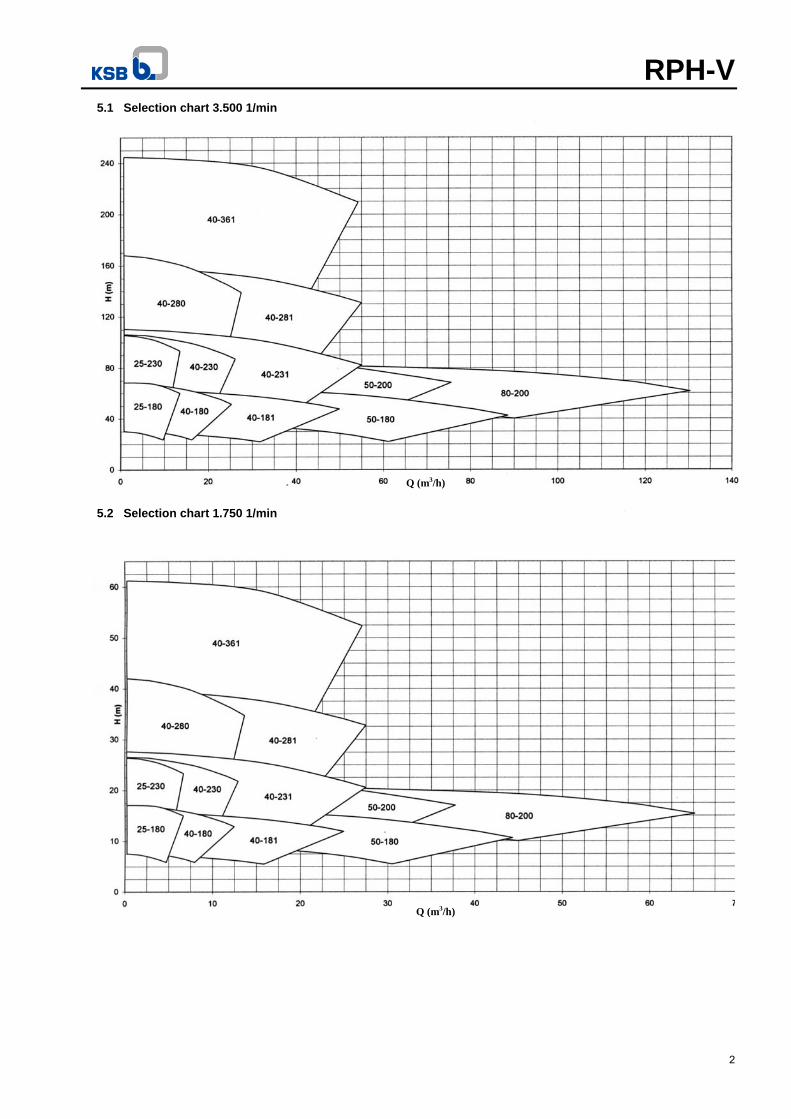
5.1 Selection chart 3.500 1/min
5.2 Selection chart 1.750 1/min
Q (m3/h)
Q (m3/h)

RPH-V
3
5.3 Selection chart 2.900 1/min
5.4 Selection chart 1.450 1/min
Q (m3/h)
Q (m3/h)

RPH-V
4
6. Product features / Benefits
Option: Grease lubrication
Option: Soleplate (circular flange) acc. to: ASME B16.47 Class 150# Serie-A
Bearings exceed service life specified by API 610, reducing maintenance expenditure and work
Rigid coupling with spacer to make easy the maintenance of mechanical seal
Flanges to all standards PN 40 equivalent (ASME Class 300)
Seal chamber acc. to API 610 accommodates all mechanical seals to API 682
Spacing between shaft guide bushing acc. to API 610

RPH-V
5
7. Technical data
Pump Size
Uni
ty
25-1
80
25-2
30
40-1
80
40-2
30
50-2
00
80-2
00
40-1
81
40-2
31
40-2
80
40-2
81
40-3
61
50-1
80
Volute type -- Simple
Impeller
- Outlet width
mm
6 6 6 6,2 10,5 14 7,8 7,7 7,5 7,7 7,9 10,9 - Inlet diameter 48 48 58 57 88 105 75 75 61 71 69 88 - maximum diam. 179 224 180 224 205 207 180 230 278 278 343 180 - minimum diam. 120 180 130 180 164 166 130 180 220 230 280 140
Sealing chamber size (Acc.to API 682 Table 1) -- 4
Bearing type / Lubrication 6313C3 / oil
Shaft diameter
- in the sealing chamber (D)
mm
50
- in the bearing 65 - in the coupling 32 - in the impeller 24 27
Shaft deflection As per API 610 11th edition
Pressure limits Max.operating pressure bar 35 2)
Max.test pressure bar 1,5 times the operating pressure or as per API 610 11th edition Flanges -- ASME B16.5 Class 300 RF Temp.limit Max.fluid temp. ºC 230 3)
Driver Maximum Value P/n 1) kW / rpm 0,019 0,032
Motor
n = 1450 rpm
kW
28 47 n = 1750 rpm 33 56 n = 2900 rpm 55 93 n = 3500 rpm 67 112
1) Values indicated refer to shaft in material A434 4140CL.BB and impeller in A216WCB & temperature < 100ºC. 2) Pressure limit refers to piping in material A106. 3) Temperature limit refers to bearing bushes in material Peek. For other condition, please consult KSB. 8. Materiais table (reference for main parts)
Part No. Description Variant S5 Variant S6 Variant A8
102 Volute casing A 216 Grade WCB A 216 Grade WCB A 351 Grade CF8M
161 Casing cover A 216 Grade WCB / A 516 Grade 65
A 216 Grade WCB / A 516 Grade 65 A 351 Grade CF8M
210 Shaft A 434/4140CL.BB A 434/4140CL.BB A276 Type 316
230 Impeller A 216 Grade WCB A 743 Grade CA6NM A 743 Grade CF8M
350 Bearing housing A 216 Grade WCB A 216 Grade WCB A 216 Grade WCB
411.10 Joint ring Spiral SS316 -Graphite Spiral SS316 -Graphite Spiral SS316 -Graphite
502 / 503 Wear ring AISl 420 Hard AISl 420 Hard AISl 316 Hard Faced
711 Rising A106 Grade B A106 Grade B AISl 316
902.01 / 920.01 Casing bolts / hex.nut A193 Grade B7 / A194 Grade 2H
A193 Grade B7 / A194 Grade 2H
A193 Grade B7 / A194 Grade 2H
Other materials acc. to API 610 are available on request.
RPH-V
6
9. Design details 9.1 Pump casing Radially split, consisting of volute casing and casing cover. Volute casing with casing wear rings. Casing cover with casing wear rings, depending on axial thrust balancing. 9.2 Impeller Closed radial impeller, impeller wear ring on the suction side. Discharge side wear ring only on hydraulically balanced impellers. 9.3 Balancing Balancing of axial thrust by sealing gap and balancing holes (if required). 9.4 Minimum flow Unless specified otherwise in the individual characteristic curves, the following applies: Qmin = 0,1 . Qopt. for short operation Qmin = 0,3 . Qopt. for continuous operation 9.5 Bearing lubrication Bearing bracket – oil fill in 0,5 l. Lubricating oil types C 46 DIN 51 517 or SAE 20 W/20 HD shall be used. On the standard pump design, the bearing bracket is uncooled. NPT threads are provided for constant-level oiler, oil drain and vent plug. The bearings are designed for at least 25,000 operating hours as per API 610/11th edition. During pump standstill the oil level can be checked against the center of the oil level sight glass. 9.6 Shaft Depending on installation following shafts are necessary: pump shaft, intermediate shaft and drive shaft. The shafts are coupled by split coupling. 9.7 Shaft sealing The pump is fitted with mechanical seals or gland packing (special variant). The mechanical seal chamber is designed in acc. to API 610, 11th edition. Mechanical seals are provided in cartridge design only (API 682)! Sealing plans with an external source (plans 32,52,53,54) to lubricate mechanical seal faces in order to avoid dry run during start-up. For other sealing plans and gland packing applications consult KSB. 9.8 Direction of rotation Clockwise, viewed from the drive end. 9.9 Bearing guides Sliding type in Peek material with shaft protecting sleeve.
9.10 Bearing guide lubrication The following possibilities are available:
a) Pumped liquid: When the product have lubricant characteristics, with a maximum of 20 p.p.m. of impurity and particle with 10 m. Each bearing receives injection through a piping connected to the rising pipe. b) Clean water of external source (optional): Water injection is done in all bearings through an external connection located above the mounting plate.
9.11 Soleplate sealing Flexible graphite packing rings with wire reinforcement to control fugitive emissions - Teadit Style 2000IC: - Temperature: -240 ~ 450 ºC - Pressure: up to 400 bar - pH: 0 ~14 9.12 Surface Coating
Type A1 – Standard surface coating for material variants S5 e S6 up to 90ºC.
Preparatory treatment
Grease-free / steel shot blasting ISO 8501-1 SA 2 ½.
Primer 1 coat - 100 m thick (dry) – Zinc phosphate epoxy.
Finish coat
Internal surfaces:
Without
External surfaces: Acrylic aliphatic polyurethane RAL 5002 blue 1 coat - 70 m thick (dry).
Type A2 – Standard surface coating for material variants S5 e S6 from 90ºC up to 230ºC.
Preparatory treatment
Grease-free / steel shot blasting ISO 8501-1 SA 2 ½.
Primer 1 coat - 50 m thick (dry) - Zinc inorganic silicate.
Finish coat
Internal surfaces:
Without
External surfaces: Monocomponent modified silicate Aluminum 800 1 coat - 35 m thick (dry).
Notes: - Material combinations C6, A8 and D1 do not have coating. - Special surface coating available on request. 10. Pump selection RPH-V pumps use the same published curves as horizontal version RPH, however items 10.1 until 10.4 should be considered for the correct pump selection. 10.1 Pump head The reference line to define the pump head and capacity is the pump discharge flange (DN2). The performance curve does not consider pressure losses in the suction strainer, discharge curve, column bearings, rising piping and internal circulation for bearing lubrication. The pump total head is the sum of following items: - Installation head, - loss in the straight discharge column. - loss in the discharge curve (elbow) , and - loss in the strainer.

RPH-V
7
10.2 Pressure losses Piping losses – Head losses in straight pipes in 100 m of pipe (in m) Nominal flow Nominal diameter
m3/h 40 50 80 100 150 1 0,22 0,08
1,5 0,50 0,17 2 0,80 0,28 3 1,80 0,60 0,05 4 3,00 1,05 0,10 5 4,70 1,60 0,15 0,05 6 6,60 2,20 0,20 0,07 8 11,50 3,90 0,35 0,13 10 17,00 5,70 0,50 0,20
12,5 26,00 8,50 0,80 0,28 15 37,00 12,50 1,10 0,40 0,05
17,5 47,00 16,00 1,40 0,50 0,06 20 63,00 21,50 2,00 0,70 0,09 25 95,00 33,00 3,00 1,10 0,13 30 45,00 4,20 1,50 0,20 35 61,00 5,70 2,00 0,24 40 78,00 7,00 2,50 0,30 45 100,00 9,00 3,10 0,40 50 11,00 3,80 0,50 60 16,00 5,50 0,70 70 21,00 7,20 0,90 80 26,50 9,20 1,20 90 34,00 12,00 1,40
100 40,00 14,00 1,80 120 58,00 20,00 2,50 140 80,00 27,00 3,30 160 35,00 4,25 180 43,00 5,30 200 50,00 6,50
Piping losses – Head losses at 90º elbow (in m) Nominal flow Nominal diameter at pump discharge nozzle
m3/h 25 40 50 80 3 0.02 4 0.04 5 0.07 0.01 6 0.10 0.02 8 0.18 0.03 0.01 10 0.28 0.04 0.02
12,5 0.43 0.07 0.03 15 0.62 0.10 0.04
17,5 0.85 0.13 0.05 20 1.11 0.17 0.07 0.01 25 1.73 0.26 0.11 0.02 30 2.50 0.38 0.16 0.02 35 0.52 0.21 0.03 40 0.68 0.28 0.04 45 0.86 0.35 0.05 50 1.06 0.43 0.07 60 1.52 0.62 0.10 70 2.08 0.85 0.13 80 1.11 0.17 90 1.41 0.21 100 1.73 0.26 120 2.50 0.38 140 0.52 160 0.68 180 0.86 200 1.06 250 1.65 300 2.38
Strainer losses (in m) – curves refer to suction nozzle nominal diameter DN1.
10.3 NPSH The NPSH values indicated in the individual performance curves were measured on impellers without hydraulic balancing. They correspond to a 3 % drop of the pump head. Generally a value of NPSHavailable - NPSHpump 0,5 m is desirable (for hot water applications please contact KSB). 10.4 Efficiency The efficiencies specified in the performance curves refer only to the hydraulic pump without losses. Axial thrust balancing of the impeller, fluid viscosity, a larger impeller clearance gap, the shaft seal type, drive shaft and thrust bearing losses reduce the pump’s overall efficiency. Efficiency was measured using a clearance gap to AN 1501, group 2 and an inlet pressure of 2 to 3 bar. The efficiency is stated in the individual performance curves of horizontal version (RPH). 10.4.1 Power consumption per guide bearing
0
50
100
150
200
250
0 500 1000 1500 2000 2500 3000 3500 4000
0.03 0.1 0.2 0.3 0.4 0.6 0.7 kWH(m)
rpm
Note: Power consumption of mechanical seal should also be considered. 10.5 Drive Direct or indirect by electric motor, engine or turbine, if an internal combustion engine has been specified, special care shall be taken when selecting the type of coupling to be used. 10.6 Motor selection When determining the motor size, consideration shall be given to the efficiency determined and the power margins as per API 610.
Motor rating Power margin up to 22 kW 22 to 55 kW above 55 kW
25 % 15 % 10 %
0
0.1
0.2
0.3
0.4
0.5
0.6
0 25 50 75 100 125 150 175 200 225Q(m3/h)
(m)
50
80
100
Q (m3/h)

RPH-V
8
10.7 External nozzle forces and moments
Pump sizes
Discharge nozzle
Forces (in N) Moments (in Nm)
Fx Fy Fz Fres Mx My Mz Mres
25-180 710 580 890 1280 460 230 350 620
25-230
40-180
710 580 890 1280 460 230 350 620 40-230
40-280
40-181
710 580 890 1280 460 230 350 620 40-231
40-281
40-361
50-180 710 580 890 1280 460 230 350 620
50-200
80-200 1070 890 1330 1930 950 470 720 1280

RPH-V
9
11. Installation depths 11.1 – Rectangular Soleplate (see item 14.1)

RPH-V
10
11.2 – Circular soleplate (see item 14.2)

RPH-V
11
12. Sectional drawing (part 1/2) – reference only
Detail of bearing housing for grease lubricated bearing and slip throwers

RPH-V
12
Sectional drawing (part 2/2)
13. Main parts list
Description Part nº Description Part nº Description Part nºVolute casing 102 Bearing cover 360 Bearing sleeve 529.15 Strainer (optional) 143 Spider 383.15 Bearing sleeve 529.21 Casing cover 161 Spider 383.21 Constant level oiler 638 Pump shaft 211 Spiral wound 411.31 Rising 711.1 Intermediary shaft 212 Mechanical seal 433 Rising 711.2 Drive shaft 213 Lantern ring 458 Suspension piping 713.1 Impeller 230 Packing 461 Suspension piping 713.2 Bearing 321 Wear ring 502 Soleplate 893 Drive lantern 341 Impeller wear ring 503 Impeller nut 922 Bearing bracket lantern 344 Shaft prot.sleeve 524 Bearing nut 923 Bearing casing 350 Center sleeve 526

RPH-V
13
14. Pump dimensions – General arrangement drawing 14.1 - Rectangular soleplate

RPH-V
14
14.2 – Circular Flange

RPH-V
15
15. Pump dimensions 1) 15.1 Table 1
PUMP SIZE
PUMP NOZZLES a a1 e e1 (min) e2 (min) F DN1 DN2 DN3
25-180 40 25 40 214 120 105 65 240 140
25-230 40 25 40 206 120 125 65 240 140
40-180 50 40 80 224 130 105 80 260 160
40-181 50 40 80 228 130 110 80 260 160
40-230 50 40 80 216 130 130 80 260 160
40-231 50 40 80 230 140 135 80 280 160
40-280 50 40 80 234 140 160 80 280 160
40-281 50 40 80 235 140 160 80 280 160
40-361 50 40 80 242 150 195 80 300 160
50-180 80 50 80 248 150 120 100 300 160
50-200 80 50 80 236 150 125 100 300 160
80-200 100 80 150 271 185 130 125 370 200
15.2 Table 2
PUMP SIZE
SOLEPLATE
CIRCULAR FLANGE 2) RECTANGULAR
Nominal pipe size A B D (min.) 3) t L1 (min.) B1 (min.) t1
25-180 26” 247 125 610 66,7 690 470 31,7
25-230 28” 247 150 660 69,9 720 470 31,7
40-180 28” 252 160 660 69,9 760 470 31,7
40-181 28” 252 160 660 69,9 760 470 31,7
40-230 30” 272 155 711 73,1 770 480 31,7
40-231 30” 272 155 711 73,1 770 480 31,7
40-280 32” 297 155 762 79,4 800 550 31,7
40-281 32” 297 155 762 79,4 800 550 31,7
40-361 36” 337 130 864 88,9 830 630 31,7
50-180 28” 257 165 660 69,9 770 470 31,7
50-200 26” 227 130 610 66,7 700 470 31,7
80-200 30” 235 170 711 73,1 800 530 31,7 1) Dimensions in mm, except where noted. 2) Dimensions according to ASME B16.47 Class 150# RF Serie A. Standard materials for a maximum working pressure of 13,5 bar at 200ºC:
- Casted: A216 WCB (CS) and A351CF8M (SS). - Forged: A105 (CS) and A182 Gr. F316 (SS).
Others materials, rating class or different flange thickness upon request. 3) D is the minimum pipe inside diameter.

RPH-V
KSB Bombas Hidráulicas SA Rua José Rabello Portella, 400 Várzea Paulista SP 13220-540 Brazil http://www.ksb.com phone.: 55 11 4596 8500 Fax: 55 11 4596 8580 SAK – KSB Customer Service e-mail: [email protected] Fax: 55 11 4596 8656
A13
16.0
.2E
/5 (1
316.56/02-EN)
31
.03.
2014