to - apps.dtic.mil · afml-tr-65-315,part 11 ablative plastic char-acterizationi m soli-d...
TRANSCRIPT

UNCLASSIFIED
AD NUMBER
AD814146
NEW LIMITATION CHANGE
TOApproved for public release, distributionunlimited
FROMDistribution authorized to U.S. Gov't.agencies and their contractors; CriticalTechnology; MAR 1967. Other requests shallbe referred to Air Force Materials Lab.,Wright-Patterson AFB, OH 45433.
AUTHORITY
AFML ltr, 7 Dec 1972
THIS PAGE IS UNCLASSIFIED

AFML-TR-65-315,PART 11
ABLATIVE PLASTIC CHAR-ACTERIZATIONi
M SOLI-D PROPELLANT EXHAUST
J. D. Batchelor
Atlantic Research Corporation
TECHNICAL REPOkT AFML-tR-65-315,PART 11l
March 1967
This document is subject. to special export controls and each transmittal toforeign gay *nments or foreign nationals may be mode only with prior approvalof the P. -s and Composites Branch, MAN C, Nonmetallic Materials Division,Air Force Mrterials Laboratory, WrightOatterson Air Force Base, Ohio 45431.
Air Force Materials Laboratory
Research and Technology Division
Air Force Syistems CommandWriqht-Patterson Air Force Base, Ohio
InI

NOTICES
Whgn GoVernment drawings, specifications, or other data are used for anypurpose other than in connecion with a definitely related Government procure-meit operation, the United States Government thereby incurs no.responsibilitynor any obligation whatsoever; and the fact that the Government may have
* formulated, furnished, or in any way suppliedthe said- drawings, specifications,or other data, -is not to be regarded by implication or otherwise as in anymanner licensing the holder or any otherperson or corporation, or conveyingany rights or permission -to manufacture, use, or sell any patented inventionthat may, in any way be related thereto.
Copies of this report should not be returned to the Research and Tech-nology- Division unless return is required by security considerations,contractual obligations, or notice on a specific document.
AF-WP-0-FEB 65 1500

f€
AFML-TR-65-315,PART 11
4 A
ABLATIVE PLASTIC -CHARACTERIZATIONIN SOLID PROPELLANT1EXHAUST
J. D. Batchelor
Atlantic Research Corporation
I
This document is subject to special export controls and each transmittal toforeign governments or foreign nationals may be made only with prior approvalof the Plastics and Composites Branch, MANC, Nonmetallic Materials Divisibn,Air Force Materials Laboratory, Wright-Patterson Air Force Base, Ohio 45433.
'Na, I

FOREWORD
This report was prepared by J. D. Batchelor of Atlantic Research Corp,-oration, Henry G. Shirley Memorial Highway at Edsall Road, Alexandria,Virginia under USAF Contract No. AF 33(615)-1631. This contract was initiaiedunder ProjR.ct No. 7340, "Nonmetallic and Composite Materials," Task No. 7.34001,"Thermally Protective Pastics and Composites." The work was administered underthe direction of the Nonmetallic Materials Division, AF Materials Laboratory,Research and Technology Division, wit: Mr. Paul F. Pirrung as project er.gineer,.
ThiL. report covers work accomplialied from 1 July 1965 to 31 January 1967.
The manuscript was released by author, March 1967 for publication as anRTD Technical Report.
This technical report has been reviewed and is approved.
R. G. SPAIN, Acting ChiefPlastics and Composites BranchNonmetallic Materials DivisionAir Force Materials Laboratory
~ii

ABSTRACT
The purpose of this program was to characterize ablative plastics forservice in the nozzle region of solid propellant motors. Evalluation of speci-mens provided by the Air Force Materials Laboratory was acco.nlished by exposureto a realistic chemical, mechanical, and thermal environment jLn a subscale, high-velocity motor test. This report describes the work of the Binal nineteen monthsof a thirty-t.vo month program. The standard test method developed in the previ-ous year (AFL-TR-65-315) was used for thirteen firing tests,. Based on the firsttwo of these firings, -flat laminate specimens were chosen asj standard becausechar rate data could be obtained and specimen fabrication was greatly simplified.Four replicate specimens of each composition were used to provide reliable data.
In the final eleven firing tests, seventeen different resin or resin mixtureswere compared with a standard commercial phenolic with either graphite or carboncloth reinforcement. Two resins (naphthalene diol and phenylphenol phenol for-
maldehyde) gave significantly better results than the standard. Several otherresins, including a chrome phenolic, polyphenyi, polyimide,, and 2-7 dihydroxy-naphthalene phenol formaldehyde, showed either similar performance or promisefor improved performance.
"This document is subject to special export controls and each transmittal to
foreign governments or foreign nationals may be made only with the prior approval
of the Plastics and Composites Branch, MANC, Nonmetallic Materials Division,Air Force Materials Laboratory, Wright-Patterson Air Force Base, Ohio 45433."
iii

TABLE OF CONTENTS
PAGE
1.0 IntroductIon. .. ......... ....... ..........
2.0 Summary .. .. ..... ........... ......... ...... 2
3.0 Rocket Motor Test Method .. .. .. ........ ..........
A4. Propellant Description. .. ..... .......... ...... 3
B. Test Configuration .. .. ......... ............. 3
C. Post tiring Analysis. .. ........ ...... .. ... ....... 4
4.0 Results .. . ..... ........ ........... .... ..... 5
5.0 Discussion. .. ..... .......... ......... ..... 6
A. Reproducibility of Firing Conditions .. .. ... .......... 6
B. Selection of Standard Reinforcement Orientation .. .. ... ..... 6
C. Delamination in Flat Laminates . . . .. .. .. .. .. .. .... 7
D. Performance of Control Standard Composites. .. ...... ..... 8 jE. Comparison of Various Resin Systems .. . . . .... ..... .... 9
1. Phenolic Type Resins. .. .. ..... ............. 9
2. Polyarylene Resins. .. ..... .......... ...... 9
3. Heterocyclic and Miscellaneous Aromatics .. .. ......... 10
4. Resin Blends .. .. . ....... ..... .. ... 10
iv

LIST Ore TABLES
TABLE PAGE
I Characteristics of Arcade-ne i27A Propellart 12.. . i!
I I D e s r ip ti o ofl T e 5 Sp ecim en s . . . . . . . . . . . . 13
IV Lcaton .Spcmn Tete inFrngAD1 . . . ..,. . 17VI Locatin of Specimens Tested in Firing ASD-11 .. . . 18
VIV Location of Specimens Tested in Firing ASD-13 .. . . 20
VII Location of Specimens Tested in Firing ASD-14 .. .. ... 21
I Location of Specimens Tested in Firing ASD-15 .. .. . .. 22
VII Location of Specimens Tested in Firing ASD-17 .. . . 24
VIII Location of Specimens Tested in Firing ASD-184.. .. . .. 25
XIX Location of Specimens Tested in Firing ASD-19 . . . 26
X Location of Specimens Tested in Firing ASD-20 .. .. . .. 27
XI Location of Specimens Tested in Firing4SD-1 . 28
XII Qouantii Dat fome eti Firing ASD- 1 .. .. .. .. 29
7|
XIII Quanttii Dataff om Firing A SD- 1 ..... . . 32
XIV Qouanati Dat fomen Firedin ASD-12 AS.-2 .. .. . .. 273
XVI Quantitative Data from Firing ASD-13 .. .. .. #.. ... 34
I
XXI Quantitative Datt from Firing ASE-14 o .a........... . .5
XII Quanattpive Dat e from Firing ASD-15 . ... . 36
~V
VII Loaio fSpcmesTetdinFrigAS-4. . .. .2
,X Lcto fSeiesTse i iigAD1....... 2X oato o pci.s etd-nFiig S-6 . . 2

i
LIST OF TABLES (concluded)
TABLE PAGE
XXIII Quantitative Data from Firing ASD-16 . 37
XXIV Quantitative Data from Firing ASD-17 . . .............. 38
XXV Quantitative Data from Firing ASD-18 . . . . ....... 39
XXVI Quantitative Data from Firing ASD-19 . . . . .......... 40
XXVII Quantitative Data from Firing ASD-20 . . ..... ........... I
XXVIII Quantitative Data from Firing ASD-21 .. ........... 42
XXLX Summary Comparison of Materials Performance . . . . . ... 43
vi
-7 =- . . . . . . .. .- . . . ... __.. . .. __ - i

I
LIST OF ILLUSTRATIONS
FIGURE PAGE
1. High Velocity Materials Evaluation Motor Assembly . . . . .. 46
2, Specimen Mounting Configuration ........ . . . .. . 47
3. Motor Pressure Trace for Firing ASD-9 .. ..... .. 48
4. Motor Pressure Trace for Firing ASD-10 . . . . . . . . . 49
5. Motor Pressure Trace forFiring ASD-11 .. . . . ... 50
6. Motor Pressure Trace for Firing ASD-2 ........ . 51
7. Motor Pressure Trace for Firing ASD-13 ....... 1.... 52
8. Motor Pressure Trace for Firing ASD-14 . .. . .. .... 53
9. Motor Pressure Trace for Firing ASD-15 . .. . . ... 54
10. Mo or Pressure Trace for Firing ASD-16 . . ... ........... 55
11. Motor Pressure Trace for Firing ASD-17 . ........... . 56
12. Motor Pressure Trace for Firing ASD-18 . . . ...... 57
13. Motor Pressure Trace for Firing ASD-19 . ............ 58 114. Motor Pressure Trace for Firing ASD-20 . ..... ... . 59 115. Motor Pressure Trace for Firing ASD-21 . . . . . . . .. .. 60
16. Specimens After Test ASD-9, Nozzle Ena Section . . . . . 61
17. Specimens After Test ASD-9, Center Section ..... . . . 62
18. Specimens After Test ASD-9, Motor End Section ... . . 63
19. Specimens After Test ASD-10, Nozzle End Section .... 64
20. Specimens After Test ASD-10, Center Section ...... 65
21. Specimens After Test ASD-10, Motor End Section .... . 66
22. Specimens After Test ASD-II, Nozzle End Section ....... 67 423. Specimens After Test ASD-I1, Center Section ........ 68
viI'
vii

LIST OF ILLUSTRATIONS (continued)
FIGURE PAGE
24. Specimens After Test ASD-11, Motor End Section . . . . . . .. 69
25. Specimens After Test ASD-12, Nozzle End Section ... . 70
26 Specimens After Test ASD-12, Center Section .... 71
27. Specimens After Test ASD-12, Motor End Section . . .... 72
28. Specimens After Test ASD-13, Nozzle End Section . . . . 73
29. Specimens After Test ASD-13, Center Section . . .......... 74
30. Specimens After Test ASD-13, Motor End Section . . . . . . 75
31. Specimens After Test ASD-14, Nozzle End Section . . . o . . 76
32. Specimens After Test ASD-14, Center Section .. . . . . . 77
33. Specimens After Test ASD-14, ,otor End Section .. . .. . . 78
34. Specimens After Test ASD-15, Nozzle End Section . ..... 79
35. Specimens After Test ASD-15, Center Section .. . . . . . 80
36. Specimens After Test ASD-15, Motor End Section . . . . . . .. 81
37. Specimens After Test ASD-16, Nozzle End Section ......... 82
38. Specimens After Test ASD-16, Center Section . . .......... 83
39. Specimens After Test ASD-16, Motor End Section ........ 84
40. Specimens After Test ASD-17, Nozzle End Section . . . . . . 85
41. Specimens After Test ASD-17, Center Section ......... 86
42. Specimens After Test ASD-17, Motor End Section .. ..... 87
43. Specimens After Test ASD-18, Nozzle End Section ...... 88
44. Specimens After Test ASD-18 Center Section ......... 89
45. Specimens After Test ASD-18, Motor End Section . . . . . . 90
46. Specimens After Test ASD-19, Nozzle End Section . . . . 91
47. Specimens After Test ASD-19, Center Section ......... 92
48. Specimens After Test ASD-19, Motor End Section . . . . . . o 93
viii

LIST OF ILLUSTRATIONS (concluded)
FIGURE PAGE
49. Specimens After Test ASD-20, Nozzle End Section ...... . 94
50. Specimens After Test ASD-20, Center Section . . . ... 95
51. Specimens After Test ASD-20, Motor End Section .... . 96
52. Specimens After Test ASD-21, Nozzle End Section . . . . . . . 97
53. Specimens After Test ASD-21, Center Section . . . . . . . . . 98
54. Specimens After Test ASD-21, Motor End Section . . . . . . . 99
55. Delaminations Noted in Specimens Prior to Test ...... * . 100
ix

P.MrE8 NOT PtUM AM~ BLA~
1.0 INTRODUCTION
Ablative plastic materials are commonly used in solid popellant rocketmotors to protect the structural parts of the motor from the hot combustionproducts of the propellant. The efficiency and reliability with which availableablative plastics perform this function is a significant factor in the perform-ance that may -be achieved in a rocket motor. For this reason the Air Force hasmaintained a continuing interest and stipport of research and development work onablative plastic composites.
The Plastics and Composites Branch, Nonmetallic Materials Division, AirForce Materials Laboratory has supported a continuing effort to develop improvedresins and reinforcements for use in ablative composites. A necessary phase ofsuch a research program is the characterization of ablative compositions underrealistic service conditions. The behavior of candidate ablative plastics mustbe studied to indicate fruitful areas for further materials research and tomeasure the degree of success in the preparation of superior materials. Theprogram described in this report is a part of this charrcterization effort.
In the region of the nozzle of t solid propellant rocket motor ablativeplastics are used to insulate the aft closure and maintain the nozzle entrancecontour, to support and insulate the nozzle throat insert, and to serve as anexpansion cone to achieve maximum thrust. In some motors the nozzle throatinsert may be fabricated from an ablative plastic composite. The conditions whichare typical of each of these locations vary in many respects, but they do share incommon severe factors such as high heat flux and highly erosive flow conditions.
The testing and characterization of materials under conditions typical ofareas near the nozzle, such as aft closure insulation and nozzle entrance sec-tions, are the objectlues of the current program. In subscale rocket motors ofconventional design tht area near the nozzle is not large enough to provide spacefor materials evaluac'an specimens. Therefore, a special motor test techniquedeveloped at Atlantic Research Corporation in prior work was selected for adap-etation to the needs of the current program. In this test a high velocity testsection mounted between the motor chamber and the nozzle is used to expose
specimens to the desired chemical, thermal, and mechanical environment.
This report describes the final nineteen months' effort on a thirty-twomonth program to 'haracterize and compare ablative plastic materials, suppliedby the Air Force Materials Laboratory, through the use of a standardized motorexposure of the type described above. The principal effort during the firstyear was to adapt the test conditions to meet the Air Force requirements and tocharacterize the standard test. During the period of this report this standardtest method was used to study the response of a total of 156 specimens in 13firings.

2.0 S MRY
The test method developed and standardized in the first year of this programprovided a means of exposing twelve flat panel specimens simultaneously to theerosive action of a hot combustion gas flow at about Mach 0.25 conditions at 500psi. This test configuration, whichprovides a cold wall heat flux of 770 Btu/sq ft, sec, was used first to .elect a preferred standard reinforcement orien-tation for test specimens and then to compare a wide variety of developmentalresin binders. The reproducibility of the firing conditions was good in eachtest.
In the first two of the thirteen firing tests covered by this report therelative behavior of flat laminates, edge-oriented laminates, and chopped clothsquare reinforcements were examined. The decision was made to use flat laminateconstruction for the remainder of the experimental specimens. This decision wasmade because char rate data could only be obtained when the reinforcement ori-entation was parallel to the heated surface of the specimen and because the flatlaminate specimens were much simpler and less costly to prepare as input to thisprogram. The disadvantage associated with the flat laminates was the delaminationtendency which introduced a need for experienced judgment in the reduction of thetest data. Based on the data from the eleven firing tests made for materials com-parison, it was concluded that (1) delamination was an inherent problem withparallel laminate specimens, but (2) the extent of delamination was likelyaffected by the quality of the interlaminar bonding achieved in the preparationof the test specimens by laboratory methods.
Both graphite cloth and carbon cloth were used as reinforcements. A standardcommercial phenolic resin showed i.1milar erosion rates with either reinforcement;the average char rate of the phenolic/graphite cloth was somewhat higher than forthe phenolic/carbon cloth as would be expected. In a few instances the degradationrates of the standard control materials were abnormal even though no abnormalitywas evident in the observed firing conditions. It was concluded that the primarymaterials comparisons should be based on the control data obtained in the samefiring in which the experimental specimens were tested.
The data obtained on a rather wide range of resins of the type which exhibithigh thermal stability showed that it is not easy to improve on the standardcommercial phenolic resin for the service conditions used. Only two resins showedrather clearly superior performance; these were the naphthalene diol and a phenyl-phenol phenol formaldehyde syatem. Several other resins, in particular chromephenolic, polyphenyl, polyimide, and 2-7 dihydroxynaphthalene phenol formaldehyde,showed promise. The only resin which was found completely unsuited for the highlyerosive test environment was the polyphenylene oxide, a high temperature thermo-plastic material.
2

4
3.0 ROCKET MOTOR TEST METHOD
The evaluation technique used in this program consisted of subscale rocket ,motor firing tests. The chemical environment in such tests is determined by thepropellant formulation used. The configuration of the motor hardware largelydetermines the mechanical environment and the thermal environment is determinedboth by the propellant and the configuration of the specimens in the rocket motor.During the first year a standard motor test method which provided the propercombination of chemical, mechanical, and thermal conditions for the evaluationof erosion-resistant materials was selected and characterized. This work whichwas closely coordinated with the Air Force Project Engineer is fully documentedin AFML-TR-65-315. The propellant and test configuration which were used in thestandard test are briefly described in the following sections. A des,'ription ofthe procedures used to inspeet the specimens after test to determine their behavioris also given.
A. PROPELLANT DESCRIPTION
The propellant selected was a conventional aluminized solid propellant desig-nated Arcadene 127-A. hlis particular propellant was chosen by the Air ForceProject Engineer because its combustion products are typical of propellants ofprimary interest to the Air Force. The pertinent characteristics of Arcadene127-A are listed in Table I. The flame temperature of this propellant is moder-ate (57000F at 500 psia), but the combustion products are quite oxidizing.
B. TEST CONFIGURATION
The basic configuration used in this program was a high velocity motor testdeveloped in previous work at Atlantic Research. The details of the configuration,svch as the specimen mounting, the bore within the test section, and the nozzlethroat diameter, were varied during the first year's work to achieve the desiredtest severity, but the basic configuration remained unchanged.
The test hardware consisted of three distinct parts; the motor tube, thespecimen test section, and the nozzle assembly. The motor tube was a heavywalled cylinder 13 inches in diameter in which the propellant burns. The testsection consisted of a motor closure with a blast tube extension in which thespecimens Lo be evaluated were mounted. The nozzle assembly was flanged to theupper end of the blast tube. An assembly view of the complete motor test unitis shown in Figure 1.
One of the chief advantages of the high velocity motor test procedure isthe capability to test multiple specimens of simple flat panel shape in a singlefiring. The specimens were mounted in the test section to form a square bore.The total useable length in the blast tube was 10 inches; three test sections3-1/2 inches long, each containing four specimens, were placed end to end in theblast tube to achieve a capacity of twelve specimens in each test firing. Thegas velocity in the test section is determined by the ratio of the cross sectionof the square bore formed by the specimens to the area of the nozzle throat.Increasing the gas velocity through the test section increases the erosiveseverity of the test environment. The nominal conditions utilized in each testreported herein were as follows:
3

Motor Pressure - 500 psi
Duration - 30 seconds
Area Ratio in test Section - 3.1 (initial value)
As reported in AFL-TR-65-315, the measured average heat flux to a copper heat-
sink calorimeter was 770 Btu/sq ft, sec for this test configuration.
The standard specimen mountig configuration is shown in Figure 2. Theentire support piece consisted of a die-molded section of epoxy-asbestos material.Four specimens were bonded with an epoxy cement into the shaped recesses moldedinto the support pieces. These support pieces were molded to accept specimenstwo inches wide; if specimens were narrower, their width was first built up totwo inches by bonding plastic shim strips to each side of the specimen. Threesupport pieces with four specimens each and totalling ten inches in length wereinserted end to end into the steel tube of the test section for motor test. Thismounting procedure proved entirely satisfactory in all firings. In firing ASD-16and all subsequent tests a gap filled with a flexible resin was left at eachbevelled corner to provide an edgewise expansion joint in the hope of reducingspecimen delamination. This practice appeared to make no difference, either forbetter or worse.
To achieve reliable and reproducible performance a tungsten nozzle insertwas selected. The nozzle assembly consisted of a steel housing, carbon insu-lating pieces, and an entrance and expansion cone of graphite along with thetungsten throat insert. With this design a neutral pressure trace and excellentreproducibility was achieved and the throat insert could be used repetitively.
C. POST FIRING ANALYSIS
After test each specimen was examined to characterize its behavior. Eachtest section, consisting of four test specimens and the associated support piece,was cut in half, normal to the axis of the section, to expose the specimenthickness at the center o: ts length. The cut edge was cleaned by light sandingso that the heat affected zone could be distinguished. The principal data con-sisted of measurements of the post-test total thickness, char thickness, anduncharred material thickness. The average erosion rate and average char ratewere defined as follows:
Erosion rate, mil/sec =(Original thickness--Final thickness)Firing duration
Char rate, mil/sec = (Original thickness--Final uncharred thickness)Firing duration
4
I!

'4 i
4.0 RESULTS
During the period of this report a total of thirteen motor firing tests fwere carried out. In each firing test twelve individual flat panel specimenswere evaluated. Thus, the results of this portion of the program are containedin the measurements made on these 156 specimens, the description of -these speci-mens, and the parameters which define the firing conditions in each test.
Table II contains a complete description of each specimen including composition,molding conditions, and post cure conditions. Reference is also supplied to thebasic data sheet(s) which describe each specimen and its preparation.
Tables III-XV show the location of each specimen and the firing conditions ofeach test. The location chart identifies the motor and nozzle ends of the testsection and- -the position of each test panel relative to the other specimens.In Figures 3-15 the motor pressure-time curves are reproduced for each firingtest.
The measurements made on each specimen both before and after test and theaverage rates of surface erosion and char penetration are tabulated for each
firing in Tables X1iI through XXVIII. The visual appearance of each specimen is avail-able for study in Figures 16 through 54. Each photograph shows the cross sectionof one set of four specimens and the mounting fixture which held these specimensafter the unit was sectioned for examination. The original location of thesurface of each specimen at the start of the motor test is shown by the dottedlines superimposed on the photograph by means of an overlay.
The complete output of the current portion of this program is contained inthe figures and tabulations described. For those interested in the response ofindividual materials or their performance capability in an erosive environmenttypical of the nozzle entrance region these data should be carefully studied..In the following section a few of the more obvious comparisons and evaluationsare offered as a general interpretation of the data. Other factors, such asdetailed knowledge of the resin materials and behavior in other test environ-ments, should be referred to, whenever available, by the serious reader.
5
- --- .- -. - -
5.0 DISCUSSION
A. REPRODUCIBILITY OF FIRING CONDITIONS
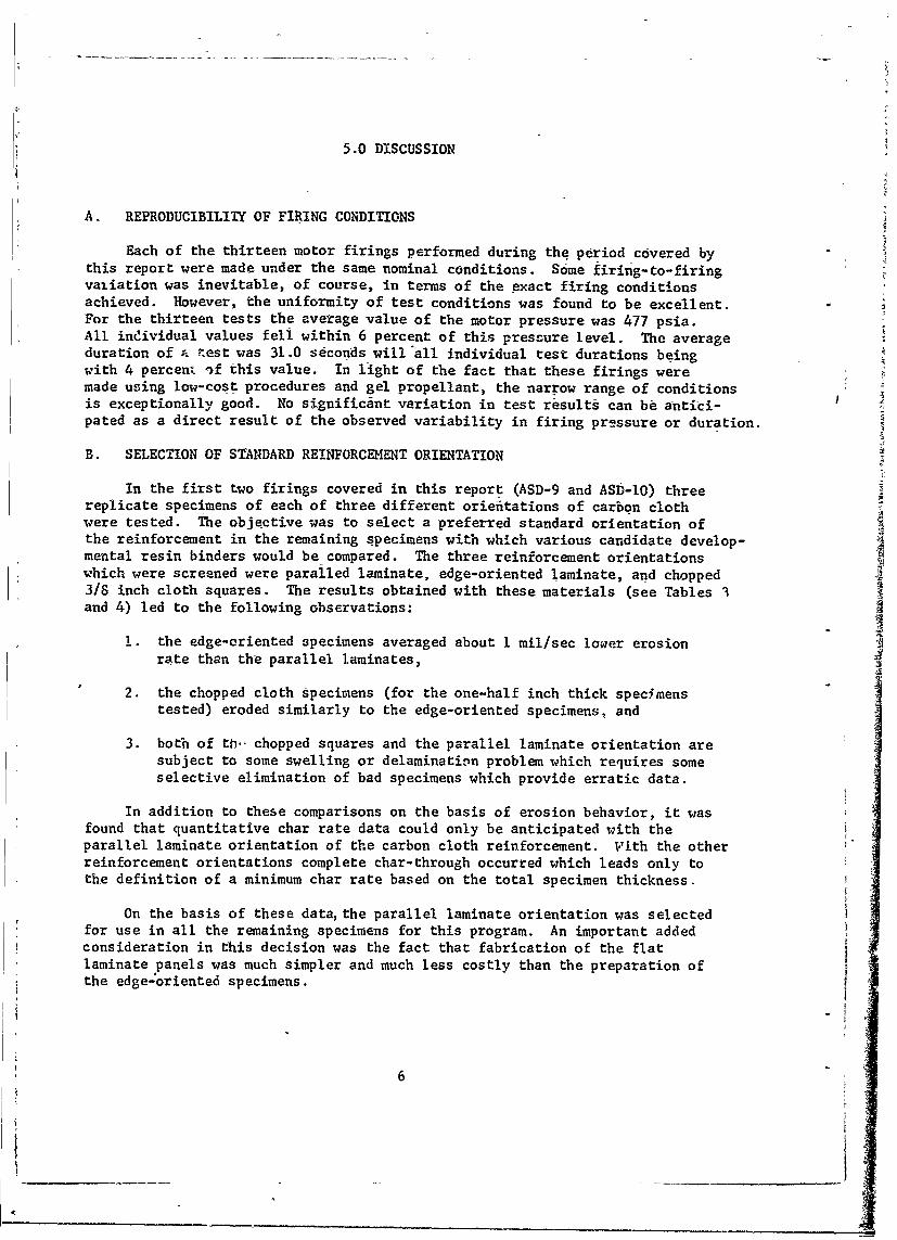
Each of the thirteen motor firings performed during the period covered bythis report were made under the same nominal conditions. Some firing-to-firingvaiiation was inevitable, of course, in terms of the exact firing conditionsachieved. However, the uniformity of test conditions was found to be excellent.For the thirteen tests the average value of the motor pressure was 477 psia.All individual values fell within 6 percent of this pressure level. The averageduration of a. test was 31.0 seconds will all individual test durations beingwith 4 percent )f this value. In light of the fact that these firings weremade using low-cost procedures and gel propellant, the narrow range of conditionsis exceptionally good. No significant variation in test results can be antici-pated as a direct result of the observed variability in firing pressure or duration.
B. SELECTION OF STANDARD REINFORCEMENT ORIENTATION
In the first two firings covered in this report (ASD-9 and ASD-l0) threereplicate specimens of each of three different orientations of carbon clothwere tested. The objective was to select a preferred standard orientation ofthe reinforcement in the remaining specimens with which various candidate develop-mental resin binders would be compared. The three reinforcement orientationswhich were screened were paralled laminate, edge-oriented laminatd, and chopped3/8 inch cloth squares. The results obtained with these materials (see Tables 3and 4) led to the following observations:
1. the edge-oriented specimens averaged about I mil/sec lower erosionrate than the parallel laminates,
2. the chopped cloth specimens (for the one-half inch thick specimenstested) eroded similarly to the edge-oriented specimens, and
3. both of th- chopped squares and the parallel laminate orientation aresubject to some swelling or delamination problem which requires someselective elimination of bad specimens which provide erratic data.
In addition to these comparisons on the basis of erosion behavior, it wasfound that quantitative char rate data could only be anticipated with theparallel laminate orientation of the carbon cloth reinforcement. Vith the otherreinforcement orientations complete char-through occurred which leads only tothe definition of a minimum char rate based on the total specimen thickness.
On the basis of these data, the parallel laminate orientation was selectedfor use in all the remaining specimens for this program. An important addedconsideration in this decision was the fact that fabrication of the flatlaminate panels was much simpler and much less costly than the preparation ofthe edge-oriented specimens.
6I _______________________

One other comparison provided by the results of firings ASD-9 and ASD-iOwhich was preliminary to thd final selection of the standard reinforcement wasthe substitution of Pluton B and Pluton H for the carbon cloth in the parallellaminate construction. Based on the average of two specimens of each grade ofPluton (bonded with SCI008, a Mil R-9299 resin but not the standard used in otherspecimens) the Pluton B appeared inferior to carbon cloth while the Pluton Happeared slightly better. No justification could be seen, however, for usingthis more proprietary type of reinforcement as a standard of comparison ratherthai carbon cloth.
C. DELAMINATION IN FLAT LAMINATES
As indicated in the section above, the choice of the parallel laminatereinforcement was made for all specimens placed in the last eleven motor testfirings (ASD-li through ASD-21). The simplicity of this construction and thecapability to measure char rates were sufficient reasons for this decision.Nonetheless, the price that had to be accepted was the ever-present danger ofspecimen delamination and blistering during test.
Several comments can be made about the delamination problem experienced inthe various specimens. Of the 132 specinens contained in the last eleven firings,visible delaminations which had to be taken into account in the measurement ofpost test data were noted in 58. In about half of these instances no greatuncertainty was introduced by these delaminations, but in the remaining speci-mens the performance measurement may well have been affected. In the final sixfirings an attempt was made to relieve any restraint along the edges of thespecimens by placing a compliant filler in gaps left at the bevelled cornerswhen the specimens were mounted. It was felt that edge-wise restraint of thermalgrowth might contribute to the buckling of the surface layers. Hoever, no evi-dence was found that this possible restraint or the elimination of it played anyrole in the observed delaminations.
A positive relationship seemed to exist between the composition of the spec-"imen and its tendency to delaminate during test. This can best be illustratedby a statistical summary of the extent to which various composites evidenceddelamination. In the eleven tests under consideration a total of 33 sets offour replicate specimens were tested. One set was completely eroded away. Ofthe 32 sets which survived test,.seven had no delaminations within the set, tenhad either one or two specimens with delaminations, but fifteen sets had eitherthree or all four specimens delaminated. Almost half of all the specimen sets,and sixty percent of those sets which exhibited some delamination, had eitherthree or four specimens (out of four) delaminated. This summary is presented onlybecause it suggests that the delamination tendency is related to the compositionof the composite. It is reasonable to assume that laboratory fabrication pro-cedures, which involve spatula coating of development resins onto carbon orgraphite cloth, may yield less than optimum interlaminar bonding in the laminatedspecimens. The problem of laminar strength would be further aggravated by boththe relatively refractory nature of some of the high temperature resins and theminimum of fabrication experience with them. Visual evidence, in the form ofstriations or incipient splits, were noted in many specimens prior to test. Twoexamples of partial delaminations pre-existent in specimens when received fortest are shown in Figure 55. These pictures show the worst flaws noted in any
7

specimens, but a rather common occurrence was a noticeable striation at aboutone third of the thickness from each surface presumably related to a stackingprocedure followed in the layup of the laminates.
The most logical conclusions that can be drawn from the evidence concerning
delamination are two-fold:
1. Some delamination tendency is inherent In the test method when parallelcloth laminate specimens are tested, and
2. The interlaminer bond strength of individual specimens, as determinedby the nature of the resin binder and the details of the fabricationprocedure, affect the degree of delamination.
D. PERFORMANCE OF CONTROL STANDARD COMPOSITES
Two different standards were used as controls in the course of the elevenevaluation firings. Both control materials contained a commercial Mil R-9299
class phenolic resinm one composite was reinforced with carbon cloth and theother with graphite cloth. In each firing - t esa set of four replicate specimensof at least one of these controls was included, genera ll in the center testsection. For the purposes of the discussion in this section and the next, theaverage char and erosion rates for each set of four replicate specimens are sum-marized for each of the firing tests in Table XXIX.
The phenolic-graphite cloth control was used in a total of six firings. Infour of these (ASD-ll, -13, -14, and -15) it was the only control; in two firings(ASD-12 and -21) the phenolic-carbon cloth composite was also included. The
observed char and erosion rates in four oi the tests were quite similar; theerosion rates averaged 4.5 mil/sec (maximum deviation 7%) and the char ratesaveraged 13.0 mil/sec (maximum deviation 6%). In the last two firing tests whichcontained phenolic-graphite control specimens higher rates of erosion (about 5.8mil/sec) and charring (>14.8 mil/sec) were measured. It is possible that thehigher rates of degradation were the result either of unusual severity in thetest conditions or a variation in specimen quality; no convincing evidence isavailable to choose either explanation with certainty.
The phenolic-carbon control standard material was included in seven testfirings (ASD-12 and ASD-16 through -21). In five tests it was the only controland in two both of the controls were present. In five of the seven tests thechar and erosion rates were reproduced, the mean values being 11.6 mil/sec (maxi-mum deviation 12%) and 4.6 mil/sec (maximum deviation 10%), respectively. In theremaining two tests the erosion rates were significantly different, one beingunusually low (test ASD-17) and the other unusually high (test ASD-18). The charrates in these two tests were within the same range found in all tests. As wasnoted for the phenolic-graphite control, the divergent behavior of two of thephenolic-carbon control sets might have resulted from either undetected changesin test severity or from spacimen variability. Some indirect evidence can becited to support either assumption. First, delamination was as serious for thecontrols as for the experimental composites and the density of both of the controls(especially the phenolic-graphite) us rather low (see Table II) compared with the
8

normal value for comercial laminates which generally have a density of about1.45 gm/cc. These factors might be taken to point to a variability in the speci-men quality. On- the other hand, in two tests in particular (ASD-15 and -18) the
erosion rates of all the specimens were unusually high as well as the control
specimens. Similarly, in ASD-17 the results all appear to trend downward in step
with the phenolic-carbon control. Thus, it must be concluded that a moderateuncertainty, the source of which cannot be defined, remains in this motor testprocedure as in virtually any exploratory series of tests. It is recommended to
the reader that initial comparisons be made on the basis of the average data fromeach particular test. Whenever several tests are available, as is the case pri-marily for the control specimens in this program, the test to test variations canbe dealt with effectively.
E. COMPARISON OF VARIOUS RESIN SYSTEMS
In this final section a summary of the comparisons which can be made concerningthe-performance potential of the various resin systems it. given. The researcherdirectly involved in this area of study should .eel free to study the data for Iadditional insight into the behavior of the materY.als tested.
In order to provide a systematic discussion ti-e resins examined are organizedinto four groups in terms of the basic nature of their chemical structure. Thecomments offered are based primarily on the comparison of the experimental mate-rials with the control specimen data in the same hring as suggested above.
1. Phenolic Type Resins
A total of five developmental resins of the phenolic type were compared intests with _he standard (91 LD) phenolic. The relative performance of each of
these when compared to the control standard is as follows:
Relation to Control Standard
Firing No. Resin Char Rate Erosion Rate
13 Chrome phenolic similar similar15 Tungsten-'henolic similar poorer16 Naphthalene diol poorer better19 Phenyl aldehyde poorer poorer21 Biphenol formaldehyde similar poorer
The difficulty of improving upon the conventional phenolic with other phenolicmodifications is apparent. Only the naphthalene diol resin provided a 6ignificantimprovement in erosion resistance; some noticeable but probably not very importantloss in charring resistance was noted.
In firing ASD-14 two grades of Pluton cloth were again compared, this timewith the standard (91 LD) phenolic binder. The results contradict rather weakly
the earlier comment (end of Section 5-B) in that the B grade looked a little more
erosion resistant than the H grade. Overall, it is unlikely that any significantdifference exists for the environment involved in this program.
2. Polyarylene Resins
Two resins appear to be best described as homopolymers of the polyarylene
type. The performance comparison for these are:9

Relation to Control StandardFiring No. Resin Char Rate Erosion Rate
16 Polyphenyl similar similar-17 Polyphenylene similar poorer (similar
to control average)
Here it must be concluded that no significant improvement was achieved over
the existing standards.
3. Heterocvclic and Miscellaneous Aromatics
This category is meant to cover the two polyimide specimen sets (one withgraphite cloth reinforcement and one with carbon cloth) and the two oxide-typepolymers, diphenyl oxide and polyphenylene oxide. The latter set of specimenswas completly eroded away during test and, thus, was the only material which mustbe judged as completely unacceptable in high erosion locations in a solid pro-pellant motor. The comparisons of this group of resins with the standard may beoutlined as follows:
Relation to Control StandardFirink No. Resin Char Rate Erosion Rate
II Polyimide (on graphite) similar poorer17 Polyimlde (on carbon) poorer similar (better
than control average)13 Diphenyl oxide poorer pooreri5 Polyphenylene oxide very poor very poor
This outline indicates" that no advancement in the standard art was demon-strated in this series of resins.
4. Resin Blends
A total of seven specimen sets contained resin binders that can best bedescribed as blends of two polymer structures. The performance measured for theseis shown below. The first four materials were apparently formed by the simultane-ous condensation of a mixed phenol material with formaldehyde. On the other hand,the last three materials were essentially mixtures of partially staged resins whichare subjected to final cure together in the fabrication of the laminated test panels.
Relation to Control StandardFiring No. Resin Char Rate Erosion Rate
11 Phenylphenol phenol similar betterformaldehyde
12 2-7 dihydroxynaphthalene similar similarphenol formaldehyde
18, Polyphenylene phenolic poorer similar (poorer8 othan control avg.)
18' Polyarylene phenolic poorer poorer
10

A
19 Epoxy/polyphenylene similar poorer(intractable)
20 Phenol ic/polyphenylene poorer better
(intractable)
20 P-phenylphenol phenol similar slightly betterformaldehyd e/polyphenyl ene(intractable)
In this group of resins more favorableresults were noted than in the pre-ceding groups. Several comments can be made. The phenylphenol phenol formaldehyderesin showed a significantly improved erosion resistance equalled only by thenaphthalene diol resin in group I above. The 2-7 dihydroxynaphthalene phenolformaldehyde was only a stand-off with the commercial phenolic. The mixed poly-arylene-phenolics (both the polyphenylene and the general polyarylene) were foundinferior to the standard phenolic. The effect of tl.e addition of the intractablepolyphenylene in the last three specimen sets listed _s rather difficult to inter-pret. In the epoxy system the performance was not up to the phenolic standard,but it is likely that the base epoxy would be even less suited for highly erosiveservice conditions. When mixed with the phenolic the .intractable polyphenylenefiller increased the char rate, but decreased the erosion rate. Lastly, thepresence of the intractable polyphenylene in the p-phenylphenol phenol formalde- T
hyde mixed resin provided .performance slightly better than the standard phenolicbut not as good as the system without the polyphenylene (the first material in Ithis group) which is assumed to be similar.
AA
11

TABLE I
CHARACTERISTICS OF ARCADENE 127A PROPELLANTa
Propellant Flame Temperature: 5700OF
Princ.pal Co-mbustion VolumeProducts (percent)
CO2 2.1
CO 22.2
H20 18.7
H2 25.1
HCl 15.1
SN2 8.6
H 4.1
OH 1.5
AIC1 0.4
Cl 1.7 -
A1203 (1) 27.4 gm/100 gm
iaTheoretical data calculated for 500 psia chamber pressure.
12

0 u
C6 .413 421a
u..24 CGis .. tU S.4 0' Wa W i l 000~ ~ wl C,,7CC , , C - C . ,
IT CIA*4~ C14 C- %0 1 rd o l 4
C4 Go -4 -4 co c
0 j4" S.
Q002 0 0 n
A C -4 C4 .4 i C4 .4 .. ( .-
ti. 0 .. 2 ID 0 0 Q. .4 0. 04 0. 4D 004 v.4 42 *.4 v.L C.2l: lz
1 -4 -44 t C -4 V%
440
oo: a4 00 CI N 00 A 0 a 0 a 1 1 a 0 In C
P4 u 0
00 0aI a oo0 0 00 0 00001 0 0 0 0Q , 0 0 0 0 .
0Z -t NNN ua C0 0I e0 ow Nc Nu 0 N 0
0
0a -0 00 0- 00 0 0 0 0 0C o~ o 0 0 0 0w0 0 .000 .4 Z4 toC 0n 0 0 -1. 0 v1.0 cc C, ,C C, u I I; .7 C L ' 0 I ( l C a N
U4 v.2 A. AC, ,-1 - 1u U). 00 00 04 L
0 N1
4214 0 10 C.C n 0 0 0 0 S. 0 '1 440u
Co 00 a a a a a a = o - a 2 C ,1 .0 0 C C C4 C 44 02 > .4 C: '4 C: m r .Cr4 Ov. 0.2 0 : 0 0.- 0v. MC .C mC C C 0 0 C . O
aa ulco91. 0 m.
a0 .4 -G ." .I0.o a0] U Un 004- 1. >.-7 a, a, .C.10.
C0;0C4 v487 'e; 0.' >..- 0 U -4 T C0 coca N4 m. MA 0m In. 01 10 A 4
0v.40 0 ,. Go 4 a, A N ~ >.C 04 4 0 04.C C C C C >I)~0 C CA . l > ~ . 5 A . .. .
COI .0' .CI A. A: 0 1; :a.'- a.o.- a.'. a,'. 1;' C;'~ a..- m4 o. , mm. A. . NC4 a'. .- 01
uj0 o 00 % a Am 4- 4 L n k n%
woo AA3

5C4
0C. s. I 4 .4 s- 4 s- 41 -
to
.4.414
.4 .4 4 . 4.
so 34
ofa a aa0. P. 0 . 0 . 0 0.010.0..
a4 cl C I0 tn0 a0
-4
00
1-4,
041I N 4, -?C ,4, 4 ,4
Sf0 0 0 0 0 0 0 0 s0
no 1 o 8 0 0 0 0 0 0 0 nU 0 0 0 0 0 0 4
M q- o as -- -
CI4J.N N a0- ad Cd S6 0.0 0* OX 4,1.t . 4 0 C4 4, r, a, 4, 4, 4, 01 4, 4.
0 0 0 0 0A0. a0 .0 .0 0 .0
S 0 0 0 0 0 0 0 P. a 0 v041 0
S.. .4- m'- 0.4 Os0 0t: 0.. co. O- sS 0:4 O a- 4 m -.01 .3 N O .05 q 0 .0 .5 .5 5 0-sd 34 4 34< 34 34< 04 3443 w
A 0M 3 9 " 5 10 61 .0. 00 -0 00 10 10 0 1 00. 00 03 00 . 00 1
0 m1 0, a0 ao 510 1 .4 4 is< 34< ,M s- 0. 0 U
Uo c 0 0 e 0; 0: "; O
100 1 I 0 i .4 M' 04 5- " "- C14 C% qM
M 410 0%0 rl 0%0 4.4 m U4 4 0 - N. .4IN9)
3 Ifm r4N C40 -4 -1 Is-NI s-S 4 N C C4,N
14

0 0 0
00
.0 . . -
0 0t .0
54 0 0 0a 0
0 A0
04 0 -o00 o 0o 0 0 U
CA 0 0 .10 0
0 0 U 0U
00 0 U- V0ca'
. 0D. 04 545 C 0 sON c 0-5
0 0 0-
0. 0
C,%00 w201
S 0 0 4 0w 51 00 ~ 0t 4 a 4
Es.- 0 r, 'l) M 00o Z) to W0 0 a w 0
00 0. .09z 414 0 "C tz ". 0
0 . ; 1 -4. C. 0, 0
0, a m40 = ': rd.0 .0 0 4 q
14 a0 V 40 0 0 0T
U4 r .. 5 0 0 54 4
2 0 .0 .0 .0 07*0 Q 0 0 0 30 00. u. 000 0 5 co C4 - 0ji
0 , s-5 50o 0 0 0
04 0. 00 0 0 U 0 0 .. 0C. C4 0 5' 'oe 0 u. 7 .0
50 0 0 0E4 . 4 00 0ot r, r.U u0 0. .054 '"TN P7S 0
s-4~ ~ 0' . 0 0 o . . -s-
4 wA 0 . 0 0 k In 0 UU
I" I00 0 4 c 04 0 U 0 In ni ,
0 0054 0 ' & 0J0 0 0 3 s U a.004
0 U ) N4 Ow 0 o 4 .
S . a 01 51 1 S0 .00
01 0 540 '. T .J .I go 14 1 (%
H~~ swS .1.0. 0 .0 0 500 I Os 10 00S 0) .5 0
1.. 0-(' 5.0 c' 0 5. 4 0 - 0U U) 0. 00 -t m
0. .4 0 . 0 . . 510 'n 0
0 0ca 0 .0 0 0 0. to U03 m4 0. a50 540 C3. 1 03 0r 0 .0 0n 0a.05 %4 a 54 '0 00 %n0 W1 0 05toQ1- c44
p N 1 .0 51511 w U 1. Is U INT 0 51 a =51 'S ' = =1 00 w IT0 i 04 m a 0 54
13. 0 e0. It 00 0. 0 0 0 0
P'N 45 0 00 a 00. N 00 000 0511 m a 0.0
0 4 00 4 4 41 5 54 *4 54 0 V4
C4 0 C' 0 00 C0 , n q4CqN0 0 r UN 2.0 Nl NO P : .0 0
13 m- N 0 4 In n 5n1 0 0n e4 c 4- V 0 04
540 IT.544N4 0 . 0 0 :9 IT 0. g0 U:W0 01" .0 0 00 0 ('I 1 .0
s-4 i 44 es M 04 0 N $1 511 0
0. 0.. m 0 0 0 4J 0 03 0. . 54
0 0 0 .0W 005 C '1. * 0050-40%1 500-4 I N 0 0 4 51 0 %T0 00I 0 u 05 1 N4U
4 4N 4 5444 0 C4 4054. 0 c
S~~~~ j. C)...05 0 0 .0 (10.0~~ 4 U a N . 4 00 N0
0. 011 UNl P:i -4u N 7 CN aa- 0 0000 N 00 0 0. 05405401 .0In .11 $0 t 9 0 *0 05 1 0 0. .0 54to.Z5'A 1 u2
N 0 sS N . 0 0 0 N C 0 N 511 .0 -I 0 0 s-N4 0511 N- 0 0 0 0. C11 N. N04 C14 C- 94 c.0n 4
CO NS N4C 4C O 0 S0 40 g: NCC C 0'0 0 0 0
44~~~4 00 44 000 44S. 05450 004..
0554 00W04 4 04 0n 0 .0 '0 .0 0 NO
U) Nc 0 1 0 1 2% 4 CSC o1 .0. . 0 s-I 0oo 3 3 32 C4O 4 N -4'4 N NOj .1 V 0 QI 00 . 4
0. 44.3U. 4 O C 4 9.. 0 2 06 0c 00CT %
002 .50o. .s 00 0. s.Z 0 0 154

TAI3LE II
LOCATION OF SPECIMENS TESTEDIN FIRING ASD-9
Maximum Pressure - 554 psia
Average Pressure - 477 psia
Time - 31.9 seconds
ROCKET NOZZLE
RTD -#82 RTD #78 RTD #52 RTD #90Phenolic/Pluton B Phenolic/Carbon Phenolic/Carbon Phenolic/CarbonParallel Edge Grain Parallel Chopped Squares
RTD #84 RTD #79 RTD #53 RTD #91Phenolic/Pluton H Phenolic/Carbon Phenolic/Carbon Phenolic/CarbonParallel Edge Grain Parallel Chopped Squares
RTD #94 RTD #80 RTD #54 RTD #92Polyphenylene/ Phenolic/Carbon Phenolic/Carbon Phenolic/Carbon
Carbon Edge Grain Parallel Chopped SquaresEdge Grain
MOTOR CH-AMBER
16

TABLE IV
LOCATION OF SPECIMENS TESTEDIN FIRING ASD-10
Maximum Pressure - 523 psia
Average Pressure - 460 psia
Time - 32.1 seconds
ROCKET NOZZLE
RTD #81 RTD #75 RTD #49 RTD #87
Phenolic/Pluton B Phenolic/Carbon Phenolic/Carbon Phenolic/CarbonParallel Edge Grain Parallel Chopped Squares
RTD #83 RTD #76 RTD #50 RTD #88
Phenolic/Pluton H Phenolic/Carbon Phenolic/Carbon Phenolic/Carbon
Parallel Edge Grain Parallal Chopped Squares
RTD #93 RTD #77 RTD #51 RTD #89
Polyphenyiene/ Phenolic/Carbon Phenolic/Carbon Phenolic/Carbon
Carbon Edge Grain Parallel Chopped Squares
Edge Grain
MOTOR CHAMBER
17

Ii
TABLE V
aLOCATION OF SPECIMENS TESTED IN FIRING ASD-11
Maximum Pressure - 527 psia
Average Pressure - 490 psia
Time - 30.1 seconds
ROCKET NOZZLE
RTD #127 RTD #128 RTD #129 RTD #130Phenylpheiolphenol formalde- D same same samehyde/graphitecloth
RTD #103 RTD #104 RTD #105 RTD #106Phenolic/graphitecloth Op same same N same
RTD #135 RTD #136 RTD #137 RTD #138Polyimide/graphitacloth - Wsame -- same asame
MOTOR CHAMBER
aAll specimens were flat laminate construction.
18
__t

|VTABLE VI
LOCATION OF SPECIMENSa TESTED IN FIRING ASD-12
Maximum Pressure - 520 psia
Average Pressure - 475 psia
Time - 31.1 seconds
ROCKET NOZZLE
RTD #143 RTD #144 RTD #145 RTD #1462,7-Dihydroxy-naphthalene - same same W samephenolic/graphite
cloth
RTD #99 RTD #100 RTD #101 RTD #102Phenolic/graphitecloth g same same same
RTD #55 RTD #56 RTD #57 RTD #58Phenolic/carboncloth - W same :Same same
MOTOR CHAMBER
aAll specimens were flat laminate construction.
19, 19
__ _ __ _ _ _ _ _ _ _ _ _1

TABLE V11
ILOCATION OF SPECIMN TESTED IN FIRING ASD-13
Maximum Pressure - 515 psia
Average Pressure - 460 psia
Time -30.2 seconds I
ROCKET NOZZLE
RTD #131 RTD #132 RTD #133 RTD #1341Diphenyl oxide!
graphite cloth Wsame - "-- -same same
RTD #107 RTD #108 RTD #109 RTD #1101Pheno lic /graphitecloth same -Wsame - ~ same
RTD #139 RTD #140 RTD #141 RTD #1421Chrome phenolic/graphite cloth --- osame Wsame - ---Vsame
a All specimens were flat laminate construction.
20

TABLE VIII
LOCATION, OF SPECIMENSa TESTED IN FIRING ASD-14
Maximum Pressure -542 psiaJ
Average Pressure - 483 paia
Time - 31.3 seconds
ROCKET NOZZLE
RTD #147 RTD #148 RTD #149 RTD #150Phenolic/PlutonB-I cloth same - - same same
RTD #111 RTD #112 RTD #113 RTD #114Phenol c/graphitEcloth .ame -, same same
RTD #151 RTD #152 RTD #153 RTD #154Pheno lic/P lutonH-I cloth - same - same - same
MOTOR CHAMBER
aAll specimens were flat laminate construction.
21
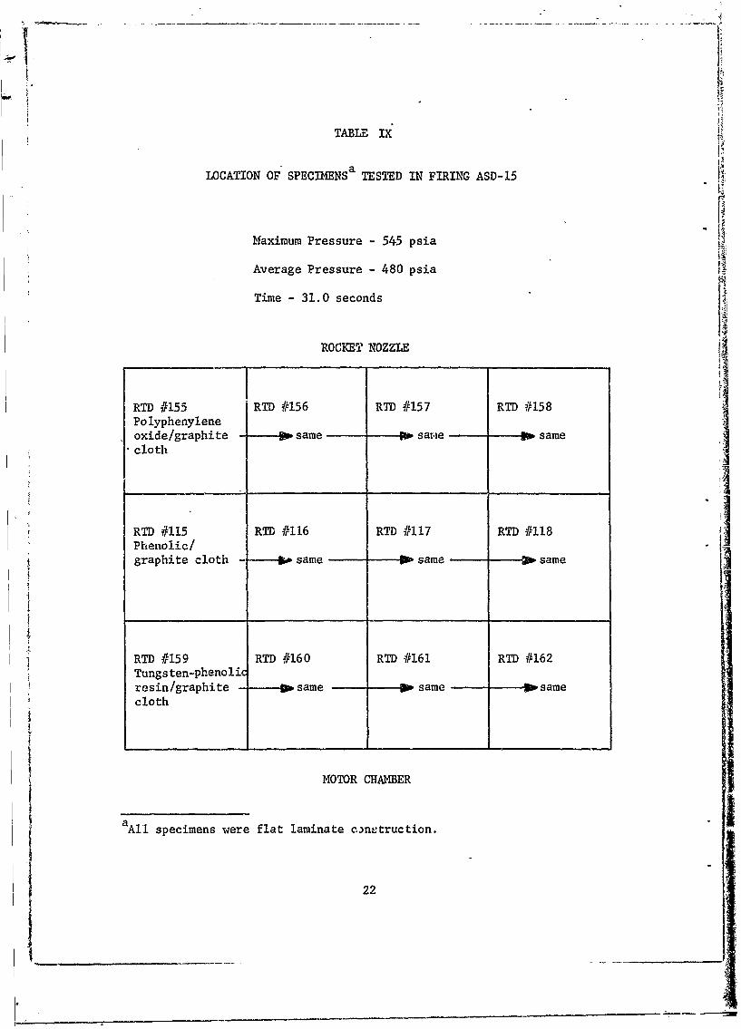
TABLU IX
LOCATION OF SPECIMENSa TESTED IN FIRING ASD-15
Maximum Pressure - 545 psia
Average Pressure - 480 psia
Time -31.0 seconds
ROCKET NOZZLE
RTD #155 -RTD #156 RTD #157 RTD #158Polyphenyleneoxide/graphite gosame DosarmiW samecloth
RTD #115 RTD #116 RTD #117 RTD #118
graphite cloth same Wsame same
RTD #159 RTD #160 RTD #161 RTD #162Tungsten-phenolicresin/graphite psame gosame psamecloth
MOTOR CHA14BER
a All specimens were flat laminate c~netruction.
22

TABLE X
LOCATION OF SPECIMENSa TESTED IN FIRING ASD-16
Maximum Pressure - 52"3 psia
Average Pressure - 460 psia
Time - 32.0 seconds
ROCKET NOZZLE 4
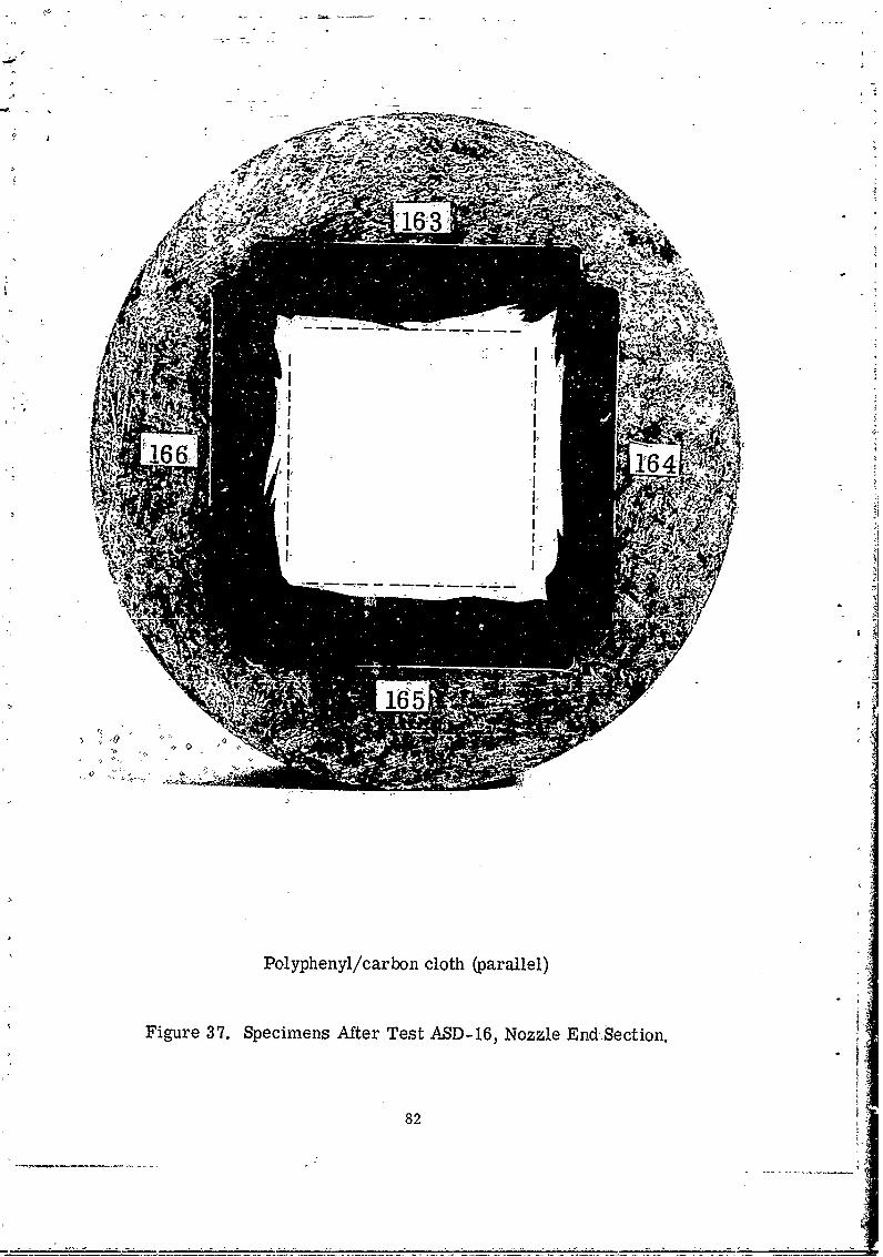
RTD #163 RTD #164 RTD #165 RTD #166Po lyphenyl /carbon cloth W same W same same
RTD '171 RTD #172 RTD #173 RTD #174Phenolic/carboncloth same - same same
RTD #167 RTD #168 RTD #169 RTD #170Naphthalene diolcarbon cloth go same go same same
MOTOR CHAMBER
aAll specimens were flat laminate construction.
23
tI

TABLE XI
LOCATION OF SPECIMENS a TESTED IN FIRING ASD-17
Maximum Pressure - 492 psi-a
Average Pressure - 455 psia
Time -31.8 seconds
ROCKET NOZZLE
RTD #199 RTD #200 RTD #201 RTD #202Polyphenylene!
carbon cloth same Wsame, same
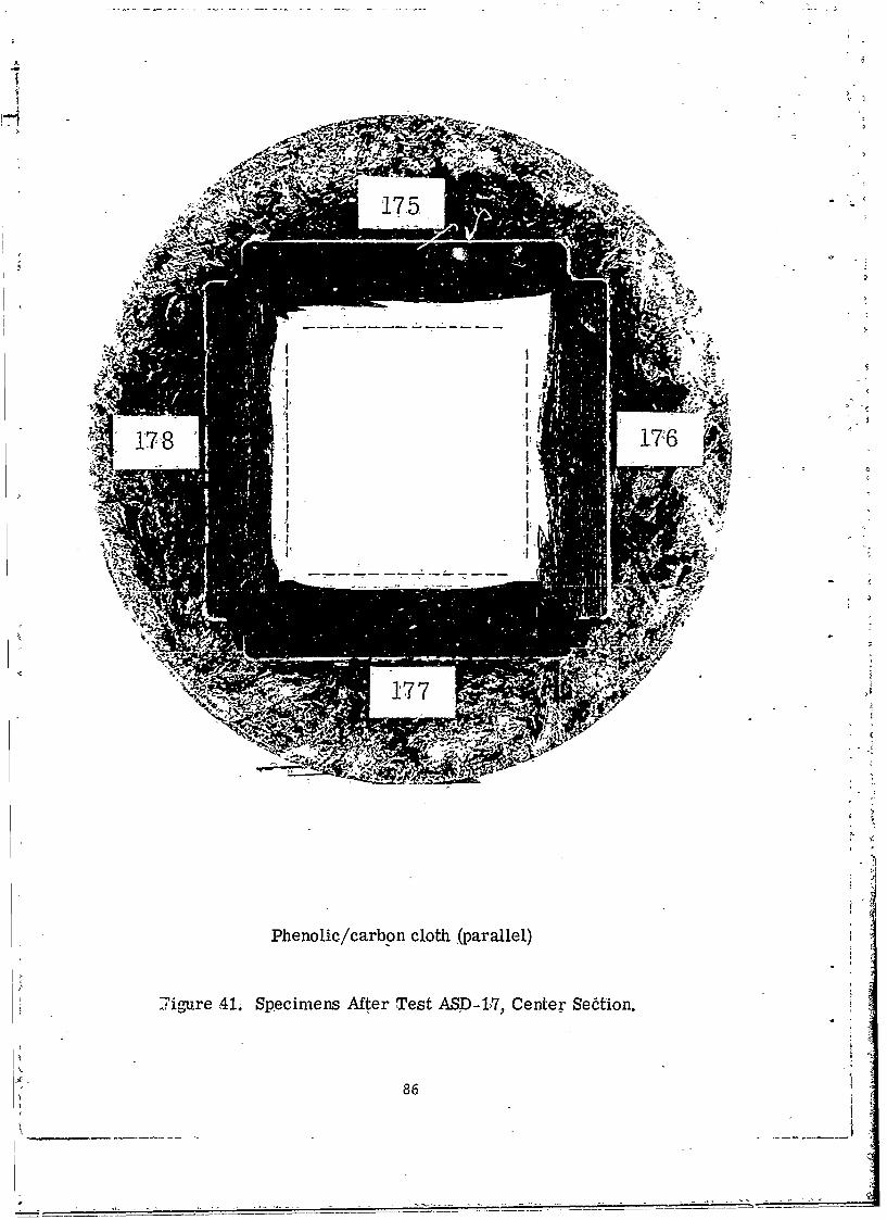
RTD #175 RTD #176 RTD #177 RTD #178Phenolic/carboncloth gosame josame josame
RTD #A203 RTD #204 RTD #205 RTD #206Pa lyimide /carboncloth same sosame same
MOTOR CHAMBER
a All specimeons were flat laminate construction.
24
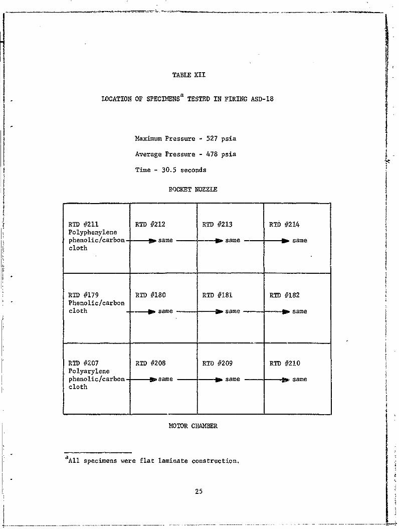
TABLE XII
LOCATION OF SPECIMENSa TESTED IN FIRING ASD-18
Maximum Pressure - 527 psia,
Average Pressure - 478 psia
Time - 30.5 seconds
ROCKET NOZZLE
RTD #211 RTD #212 RTD #213 RTb #214
Polyphenylenephenolic/carbon- same -. " same go samecloth
RTD #179 RTD #180 RTD #181 RTD #182Phenolic/carboncloth - .same Do same s same
RTD #207 RTD #208 RTD #209 RTD #210Polyarylenephenolic/carbon psame W same W samecloth
MOTOR CHAMBER
aAll specimens were flat laminate construction.
25

TABLE XIII
aLOCATION OF SPECIMENS TESTED IN FIRING ASD-19
Maximum Pressure 5'35 psia
Average Pressure -505 psia
Time - 30.4 seconds
ROCKET NOZZLE
RTD #215 RTD 11216 RO #217 RTD .01218Phenyl'Aldehyde!carbon cloth &Psame -same same
RTD #183 RTD #184 RTD #185 RTD #P186Phenolic /carbon
cloth - osame 10same gosame
RTD #227 RTD #228 RTD #229 RTD #230Epoxy/poly-phenylene/ josame same josame(intractable)carbon cloth1
MOTO~R CHAMBER
a All specimens were flat laminate construction.
26

TABLE XIV
LOCATION OF SPECIMENSa TESTED IN FIRING ASD-20
Maximum Pressure - 527 psia
Average Pressure - 480 psia
Time -- 30.4 seconds
ROCKET NOZZLE
RTD #219 RTD #220 RTD #221 RTD 222
Phenolic/poly- 2phenylene/ same - same P same(intractable)carbon cloth 4
RTD #187 RTD #188 RTD #189 RTD #190
Phenolic/carbon cloth -- Dsame so same Wsame
RTD #223 RTD #224 RTD #225 RTD #226p-phenylphenolphenol formalde-- same to same samehyde/polypheny-lene/(intractable)carbon cloth
MOTOR CHAMBER
aAll specimens were flat laminate construction.

TABLE XV
LOCATION OF SPEC3II4ENSa TESTED IN FIRING ASD-21
Maximum Pressure - 542 psia/
~ Average Pressure - 501 psia
lXime -30.8 sec~fndgr J
ROCKET NOZZLE
RD #119 RTD #120 RTD #121 RTD #122Phenolic/graphite
cloth 1Wsame Wsame gbsame
RTD #231 RTD #232 RTD #233 RTD #234Biphenol
formaldehyde/ -So same gosame obsame
carbon cloth
RTD #191 RTD #192 RTD #193 RTD #194
Phenolic/
carbon cloth So same gosame josame
MOTOXR CHAMBER
aAll specimens were flat laminate construction.
28
0 a)'4 41~ %D 0 - 0Cr) Cr) 00 r
0 -4 - CA -4 ; Cr) C34 rz
Cl 4
X4 3 0 CA -1 C h Ln a% C CA ;C A
-rI r4,4-4 ,4 iAA A A
;4$4p - 1-4 0 CN 0 0 0
n) 0 0 0 0.4 0 -4 0H "4 0) Nn 04 c- 4
0 l c
0
H~4P4
I-4 (7 0 0 '0 -*
4J- v-4'- a) -4 a a 1.0 -4 3a0- 0' £20 p -4 4 CO :$~ "4 i .
r, r-4 '0 4 a0 u c CL4c uW c 0 0 0.
m a. C0 Q V) C) C. C') 0 ) U m c'Q
a) ' CAI 14 r4 -4 T-4 CA CA.t 0 I.0C 0 V
a)0 0 )0 w00 ()0 ()0 a 0.z r $IX T4 r- $- ar 4
0) L 4N C. 40 4 L 0
0 00) m cn r
Co C

0 4 "4Js~
ul12i co co r- r-
04-'4 -t r4 '-4 LA
A A A
$4 0 C) 0$4 0 -i
00
0 40 '4-0
ci co
M~ a% 4 ON .C 0iU 141 C) 1, 10 1 4. 0.j4 r4
ciid 41
0 to 44
4-4 00
H 1 0'1 v, o % 1 :
~4Ct! Cl CV M 0M IC
"CO
10(D
6nI C'4 04) r4 rn u 0ca 0 0 0 COr4.r- LI n A n 'A CA w 40
1-40 0
0) a 4J'o o 0 m-lW
.0 coc 40)1-4j ca ' ,44
0d -% pO 0 D
0 00) 010 (1 4 a
0 pj eav 1-4t- 14 0. 1-1 e! u.,1- 00 a) 00 00..C C ci
0 4- t-4 00 C.)tO C)14 0.0 -AWr
u0 .cq %-, " 4 C: lW0.Elm= 0 0 0 0
C- 40 04o.) 0- D 0 1 4J
S0 r4Xr -i U 4$0 PW C.) P4 0
00t0.r
c4J
__________ ~ ~ ~ ~ ~ ~ ~ ~ ~ ~ ~ ~ ~ ~ 4 a)_________________ ____ ________________

.1 41--I cr) Nl tn co 0 0 Lt) c.' c') 0 % C7%04 -r4 It IA) -n -t c4r .4 .4 . C..
02 2 n % % r 1 l l
1
ca -I 0) un (7% n 00 fl- N L ani rS AA A A A A A
04
10
11 IA -0 zn 0 CA' crn 0 0 co0 40 0 0 on 0 N- 0 0 0> to.i I 0 0 C 0 0 C. 0 0 0 eJ
0
%0 an %.'0 N- %D an 0% CV) %D coP4 c ,4 en 1-4 CF) t4 en 0 IA) IAl A 0.
0 W
0 '0
cu .% %0 0 m 0 I o4c o C4 P % r n ( 0-t r 34 0
E-40
ccH 0
0' .4
00
(0) (12 (12 w C) lsr4 c 0ri c r 0 0 0- : : 0 4 t0 )0 0a 1 )0 0 a0 0 0 0 a r
0 ~~ ~ ~ ~ -W 0- Q 0T4 . ) 4 0. 0 a W a . - ) t07 V ci' r4 p M : T4 p pr4 k M C $4 r4 ' P ~ 0. 0000 0r 1 0 0 00 0w lm ca oa) 0 0'C w - 0 00 0 wCL a
4 cC) 4J J., 4 .0 CIO - .00 .. Jw-4 W0 .fklv-0.I 00 0 0 .0t .4! 0
ciAr w 0 0a0 00C 0 u Q0. -4 0000 0 .) 00 0u0 0 00u. cil V0-a r4 4 c.)O0$ 00 P44 0 i 4 00 .0 r-00 ?A0$4 00
a.:~. S~* 0- X~' 0 -x o 0 *. 4 ' Ia. ' 4 0 0 x -. c 0i 4
U 0 *r t - 0vI- 0r' 0 H- *H' 0t. *0 0 00 0 -0' - 0- W4.~ 0 I.. 0 0 . 0 r0 t-I z --I X- r-I c ,-4-4 X-i x V- - 0C i-I C - i4Z -I ci 4
rP 0 A.a0 4 Q N0 44 U 40 40 P4 0 N.0 P40u PW Q PW 0 4-1 C
10 4-a) c
cid
w 2u
31

TABLE XVIII
QUANTITATIVE DATA FROM FIRING ASD-11
Thickness.(inch) Ca rsoSpecimen Rate Rate
NO. Initial Final Char Uncharred (mil/sec) _(Mi/sec)
Phenyiphenol phenol formaldehyde/graphite cloth (parallel)
127 .504 .401 .275 .126 12.6 3.4
128 .503 .395 .319 .076 14.2 3.6
129 .503 .408 .296 .112 13.0 3.2
130 .503 .410 .318 .092 13.7 3.1
Phenolic/graphite cloth (paralllel)
103 .503 .398 .340 .058 14.8 3.5
104 .503 .387 .305 .082 14.0 3.9
105 .502 . 3 52 a .234 .118 13.0 5.0
106 .503 .33.263 .110 13.1 4.3
Polyimide/graphite cloth (parallel)
135 .503 .346 .261 .085 13.9 5.2I
136 .500 .340 .244 .096 13.4 5.3
137 .502 .342 .253 .089 13.7 5.3
138 .501 .359 .250 .109 13.0 4.7
a~leasurement of remaining materials by parts (i.e., by sum of
thickness of solid xk,terial) to eliminate effect of voids.
32

TABLE XIX
QUANTITATIVE DATA FROM FIRING ASD-12
Char ErosionThickness (inch) Rate RateSpecimen
No. Initial Final Char Uncharred (mil/sec) (mil/sec)
2,7-Dihydroxynaphthalene phenolic/graphite cloth (parallel)
143 .503 .368a .244 .124 12.2 4.3
144 .504 .369b .256 .113 12.6 4.3
145 .503 .3 75a .274 .101 12.9 4.1
146 .503 .353a .207 .146 11.5 4.8
Phenolic/graphite cloth (parallel)
99 .504 .353a .251 .104 12.9 4.9
100 .501 .386b .255 .131 11.9 3.7
101 .502 .350 .350 .000 >16.1 4.9
102 .503 . 36 7a .199 .168 10.8 4.4
Phenolic/carbon cloth (parallel)
55 .503 .380 .206 .174 10.6 4.0
56 .503 .380 .184 .196 9.9 4.0
57 .504 .367 .213 .154 11.2 4.4
58 .502 .417 .219 .198 9.8 2.7
aMeasurement of remaining materials by parts (i.e., by sum of thickness
of solid material) to eliminate effect of voids.
Delaminated thickness neglected and not included as part of final thickness.
33

-TABLE MX
QUANTITATIVE DATA FR2M FIRING ASD-13
Char ErosionSpecL'nen Rate Rate
No. Initi l Final Char Uncharred (mil/sec) (mil/sec)
Diphenyl oxide/graphite cloth (parallel)
131 .5023- .....70 .076 14.1 5.1
132 .5 02 347 a .26 0 .087 13.7 5.1
133 .502 397 .397 .000 >16.6 3.5
134 .500 .341 .341 .000 >16.6 5.3
Phenolic/graphite cloth (parallel)107 .503 .347 a .235 .112 13.0 5.2
b108 .502 .369 .255 .114 12.8 4.4
109 .503 .427 .290 .137 12.1 2.5
110 .503 .379 .241 ,138 12.1 4.1
Chrome phenolic/graphite cloth (parallel)
139 .503 .337 .283 .054 14.9 5.5
140 .503 .366 .280 .086 13.8 4.5
141 .503 .365 .305 .060 14.7 4.6b
142 .502 .382 .197 .185 10.5 4.0
aMeasurement of remaining materials by parts (i.e., by sum of thickness
of solid material) to eliminate effect of voids.
LDelaminatcd thickness neglected and not included as part of final thickness.
34
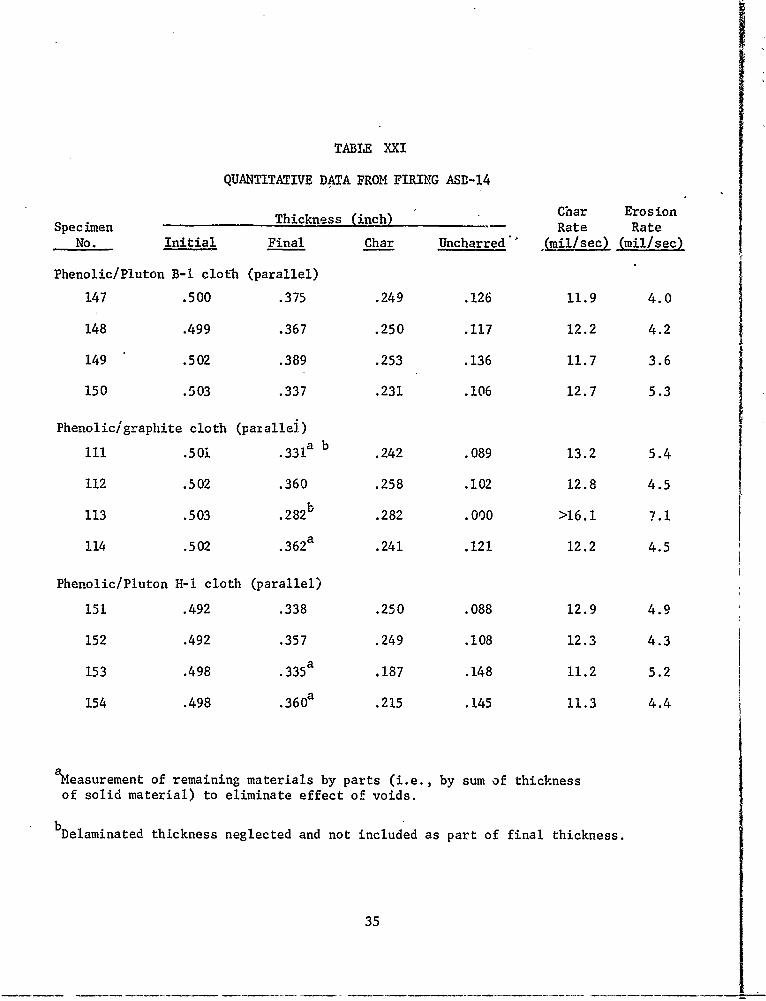
TABIE XXI
QUANTITATIVE DATA FROM FIRING ASD-14
Specimen Thickness (inch) Char Erosionate
No. Initial Final Char Uncharred" (mil/sec) (mil/sec)
Phenolic/Pluton B-I cloth (parallel)
147 .500 .375 .249 .126 11.9 4.0
148 .499 .367 .250 .117 12.2 4.2
149 .502 .389 .253 .136 11.7 3.6
150 .503 .337 .231 .106 12.7 5.3
Phenolic/graphite cloth (patallei)
111 .501 .331a b .242 .089 13.2 5.4
112 .502 .360 .258 .102 12.8 4.5
113 .503 .282 .282 .000 >16.1 7.1
114 .502 .362a .241 .121 12.2 4.5
Phenolic/Pluton H-i cloth (parallel)
151 .492 .338 .250 .088 12.9 4.9
152 .492 .357 .249 .108 12.3 4.3
153 .498 .335a .187 .148 11.2 5.2
154 .498 .360a .215 .145 11.3 4.4
ameasurement of remaining materials by parts (i.e., by sum of thickness
of solid material) to eliminate effect of voids.
bDelaminated thickness neglected and not included as part of final thickness.
35
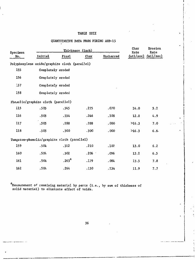
TABLE XXII
QUANTITATIVE DTA FRO4 FIRING ASD-15
Thickness (inch) Char Erosion
Specimen T n i .Rate RateNo. Initial Final Char Uncharred (mil/sec) (miilsec)
Polyphenylene oxide/graphite cloth (parallel)
155 Completely eroded
156 Completely eroded
157 Completely eroded
158 Completely eroded
Pheaiolic/graphite cloth (parallel)
115 .505 .345 .275 .070 14.0 5.2
116 .505 .354 .246 .108 12.8 4.9
117 .505 .288 .288 .000 >16.3 7.0
118 .505 .300 .300 .000 >16.3 6.6
Tungsten-phenolic/graphite cloth (parallel)
159 .504 .312 .210 .102 13.0 6.2
160 .504 .302 .206 .096 13.2 6.5
161 .504 .263a .179 .084 13.5 7.8
162 .504 .264 .130 .1.34 11.9 7.7
aMeasurement of remaining material by parts (i.e., by sum of thickness of
solid material) to eliminate effect of joids.
36

TABLE XXIII
QUANTITATIVE DATA FRO1 FIRING ASD-16
Specimen Thickness (inch)Rehar ErosiOn- ~ Specimien Rate Rate
No. Initial Final Char Uncharred (mil/sec) (mil/sec)
Polyphenyl/carbon cloth (parallel)
163 .506 .3 6 0a .164 .196 9.7 4.6164 .511 .318 .196 .122 12.2 6.0
165 .509 .387 .253 .134 11.7 3.8
Ia 166 .514 .362a .195 .167 10.8 4.7
Phenolic/carbon cloth (parallel)
171 .502 .354 .249 .105 12.4 4.6
172 .502 .423a .278 .145 11.2 2.5
173 .502 .361 .270 .091 12.8 4.4
V a174 .502 .368 .166 .202 9.4 4.2
Naphthalene diol/carbon cloth (parallel)
167 .475 .413 .267 .146 10.3 1.9
168 .472 .381 .381 .000 >14.8 2.8
169 .475 .383 .383 .000 >14.8 2.9
170 .477 .384a .260 .124 11.0 2.9
aMeasurement of remaining material by part (i.e., by sum of thickness of
solid material) to eliminate effect of voids.
37

TABLE XXIV
QUANTITATIVE DATA FROM FIRING ASD-17
Char ErosionSpecimen Thickness (inch) Rate Rate
No. Initial Final Char Uncharred (mil/sec) (mil/sec)
Polyphenytene/carbon cloth (parallel)
199 .504 .381 .239 .142 li.4 3.9
200 .503 .339 .194 .145 11.2 5.2
201 .504 . 3 88 a .229 .159 10.8 3.6
202 .503 .342 .202 .140 11.4 5.1
Phenolic/carbon cloth (para'llel)
175 .501 .391 .246 .145 11.2 3.5
176 .501 . 38 7a .199 .188 9.8 3.6
177 .502 .409 .251 .158 10.P, 2.9
178 .500 .396 .244 152 10.9 3.3
Polyimide/carbon cloth (parallel)
203 .504 .412 .344 .068 13.7 2.9
204 .502 .406 .345 .061 13.9 3.0
205 .502 .382 .309 .073 13.5 3.8
206 .504 .398 .322 .076 13.5 3.3
aMeasurement of remaining materials by parts (i.e.,by sum oif thickness of
solid material) to eliminate effect of voids,
38
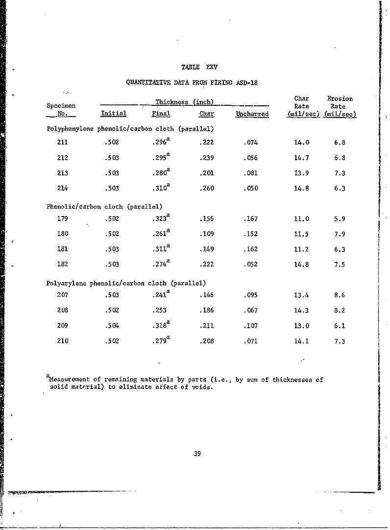
TABLE YXV
QUANTITATIVE DATA FROM FIRING ASD-18
Specimen_ Thickness (inch) Char Eros'OnSpecimen Rate Rate0
No. Initial Final Char Uncharred (mil/sec) (mil/sec)
Polyphenylene phenolic/carbon cloth (parallel)
a211 .5 02 .296a .222 .074 14.0 6.8
212 .503 .295a .239 .056 14.7 6.8
213 .503 .280a .201 .081 13.9 7.3
214 .503 .3 1 0a .260 .050 14.8 6.3
Phenolic/carbon cloth (parallel)
a179 .502 .323 .156 .167 11.0 5.9
180 .502 .261 .109 .152 11.5 7.9
181 .503 .311a .149 .162 11.2 6.3
182 .503 .274a .222 .052 14.8 7.5
Polyarylene phenolic/carbon cloth (parallel)
207 .503 .24 1a .146 .095 13.4 8.6
208 .502 .253 .186 .067 14.3 8.2
209 .504 .318a .211 .107 13.0 6.1
210 .502 .279a .208 .071 14.1 7.3
aMeasurement of remaining materials by parts (i.e., by sum of thicknesses of
solid mate.rial) to eliminate effect of voids.
39

TABLE XXVI
QUANTITATIVE DATA FR(X4 FIRNG ASD-19
kess (inh) Char ErosionSpecimen ine i Rate Rate
No. Initial Final Char Uncharred (mil/sec) Jmilsec2
Phenyl aldehyde/carbon cloth (parallel)
215 .504 .337 .288 .049 15.0 5.5
216 .505 .2 3 9a .176 .063 13.9 8.7
217 .505 .201a .201 .000 >16.6 10.0
218 .504 .3 02a .302 .000 >16.6 6.6
Phenolic/carbon cloth (parallel)
183 .503 .371 .271 .100 13.3 4.3
MS4 .502 .1 73a .090 .083 13.8 10.8
185 .502 .367 .291 .076 14.0 4.4
186 .502 .303 .178 .142 11.8 6.5
Epoxy/polyphenylene (intractable)/carbon cloth (parallel)
227 .503 .168a .100 .068 14.3 11.0
228 .504 .244a .167 .077 14.0 8.6
229 .503 . 2 8 0 a .162 .118 12.7 7.3
230 .502 .29 9a .162 .137 12.0 6.7
aMeasurement of remaining material by parts (i.e., by sum of thickness of
solid material) to eliminate effect of voids.
40

Is
TABLE XXVII
QUANTITATIVE DATA FROM FIRING ASD-20
Thickness (inch) Char ErosionSpecimen Rate Rate
No. Initial Final Char Uncharred (mil/sec) (mil/sec)
Phenolic/polyphenylene (intractable)/carbon cloth (parallel)
219 .503 .363 .269 .094 13.5 4.6
220 .504 .410 .294 .116 12.8 3.1
221 .505 .350 .238 .112 12.9 5.1
222 .504 .398 .277 .121 12.6 3.5
Phenolic/carbon cloth (parallel)IJa
187 .503 .408 a .280 .128 12.3 '3.1I
188 .505 .329a .129 .200 10.0 5.8
189 .504 .323a .189 .134 12.2 6.0
190 .503 . 3 8 8a .225 .163 11.2 3.8
p-phenylphenol phenol formaldehyde/polyphenylene (intractable)/carbon cloth (parallel)
223 .504 .346a .214 .132 12.2 5.2
224 .505 .3 9 4a .240 .154 11.5 3.7
225 .504 .382 .240 .142 11.9 4.0
226 .504 .376 .225 .151 11.6 4.2
aMeasurement of remaining material by parts (i.e., by sum of thickness of
solid material) to eliminate effect of voids.
41
7 ~~j1

TABLE XXVIII
QUANTITATIVE DATA FROM FIRING ASD-21
Char ErosionI ~~~Thickness (inch) nr EosnSpecimen Rate Rate
No. Initial Final Char Uncho-" zd (mil/sec) (mil/sec)
Phenolic/graphite cloth (parallel)a
119 .502 .333 .238 .095 13.2 5.5
120 .503 .329a .329 .000 >16.3 5.7
121 .506 .282a .282 .000 >16.4 7.3
122 .504 .371a .291 .080 13.8 4.3
Biphenol formaldehyde/carbon cloth (parallel)231 .544 .279a .140 .139 13.2 8.6
232 .543 .271a .128 .143 13.0 8.8
233 .544 .299a .165 .134 13.3 8.0
234 .541 .266 .156 .110 14.0 8.9
Phenolic/carbon cloth (parallel)
191 .503 .407 .261 .146 11.6 3.1
192 .501 .398a .237 .161 11.C 3.3
193 .502 .294a .171 .123 12.3 6.8
194 .499 .333a .236 .097 13.1 5.4
aeasurement of remaining material by parts (i.e., by sum of thickness ofsolid material) to eliminate effect of voids.
42

TABLE XXIX
SU4WARY COMPARISON OF MATERIALS PERFORMANCE
Avg. Char Rate Avg. Erosion RateMaterial (mil/sec) Imil/sec)
Phenolic/graphite control 13.0 4.5(overall average from four tests)
Phenolic/carbon control 11.6 4.6
(overall average from five tests)
Firing ASD-.I
Phenylphenol phenol formaldehyde/ 13.4 3.3graphite cloth
Phenolic/graphite cloth 13.7 4.2
Polyimide/graphite cloth 13.5 5.1
Firing ASD-12
2,7-dihydroxynapthalene phenol 12.3 4.4.formaldehyde/graphite cloth
Phenolic/graphite cloth 12.9 4.5
Phenolic/carbon cloth 10.6 a 4.1a
Firing ASD-13
Diphenyl oxide/graphite cloth 14.8a 5.2
Phenolic/graphite cloth 12.6a 4 .6a
Chrome phenolic/graphite cloth 13.5 4.6
Firing ASD-14
Phenolic/pluton B-1 cloth 12.1 4.3
Phenolic/graphite cloth 12 .7a 4.8a
Phenolic/pluton H-1 cloth 11.9 4.7
aCalculated after eliminating single divergent result, based on erosion rate.
43
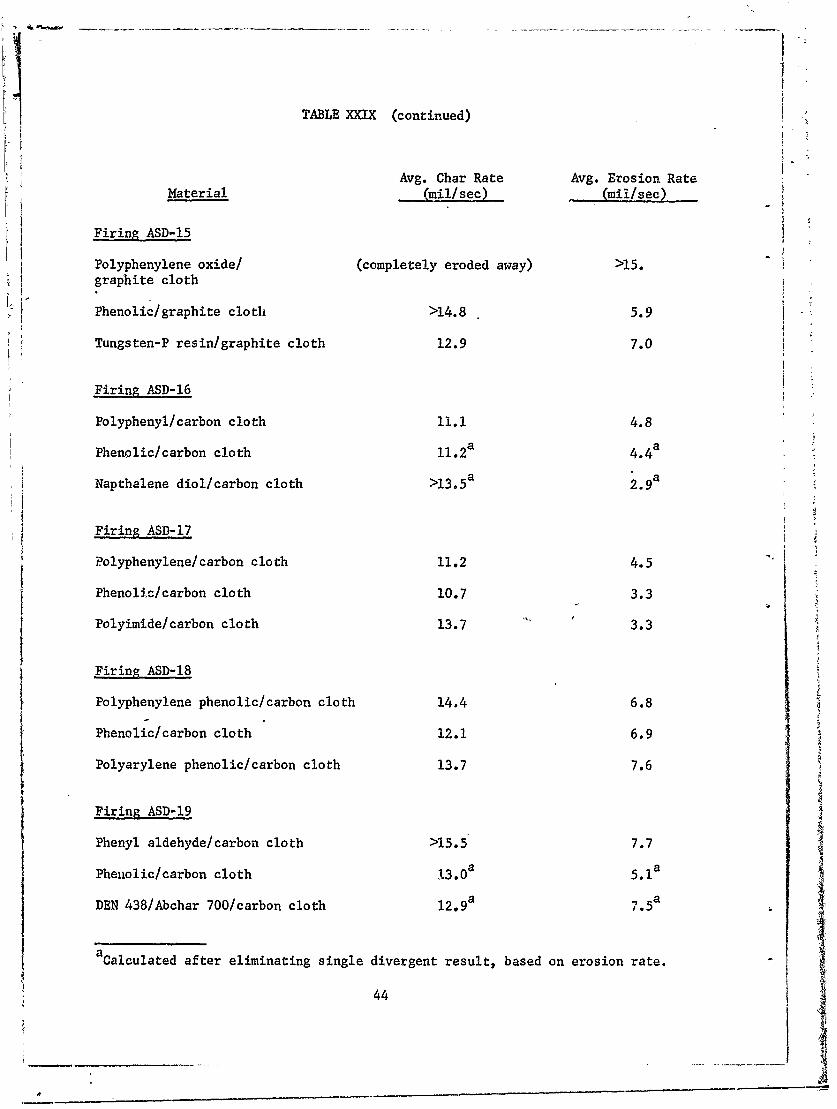
TABLE XXIX (continued)
Avg. Char Rate Avg. Erosion Rate
Material * mil/sec) (mil/sec)
Firing ASD-15
Polyphenylene oxide/ (completely eroded away) >15.graphite cloth
Phenolic/graphite cloth >14.8 5.9
Tungsten-P resin/graphite cloth 12.9 7.0
Firing ASD-16
Polyphenyl/carbon cloth 11.1 4.8
Phenolic/carbon cloth 11.2a 4.4
Napthalene diol/carbon cloth >13.5a 2 .9a
Firing ASD-17
Polyphenylene/carbon cloth 11.2 4.5
Phenolic/carbon cloth 10.7 3.3
Polyimide/carbon cloth 13.7 3.3
Firing ASD-18
t Polyphenylene phenolic/carbon cloth 14.4 6.8
Phenolic/carbon cloth 12.1 6.9
Polyarylene phenolic/carbon cloth 13.7 7.6
Firing ASD-19
Phenyl aldehyde/carbon cloth >15.5 7.7
Phenolic/carbon cloth 13.0a 5.1 a
DEN 438/Abchar 700/carbon cloth 12.9a 7 5a
a Calculated after eliminating single divergent result, based on erosion rate.
44

TABLE XXIX (concluded)
Avg. Char Rate Avg. Erosion Rate
Material (milisec) (mil/sec'
Firing ASD-20
Phenolic/Abchar 700/carbon cloth 13.0 4.1
Phenolic/carbon cloth 11.4 4.7
p-phenylphenol phenol formaldehyde/ 11.8 4.3Abchar 700/carbon cloth
Firing ASD-21
Phenolic/graphite cloth >14.9 5.7
Biphenol formaldehyde/carbon cloth 134 8.6
Phenolic/carbon cloth 12.0 4.7
45
Nozzle Assembly
-- Twelve Test Samples
HeavywallMotor Tube
Propellant10 1I
Fiue1"ihVlct aeiasEauto oo seby46,

0a0
4-1 0
0 C0
0 U)
471

t,41
44-~
4-
I CQ
I rZ
CO ID
48

t LL
-HH
A0
0
49-

fill2
I f 1 1 ! 1 1 1
-1 IZL AXE
FF L 0I t I f 1 1 1 1 1 1 . 1 3-1
fill~ 11 11 1 1
1 11 1 0
# I i f
if,-
iIi t ll)
- will 1 1 t -- -50

I fI
4
CO
I t
H-E--
F li-, ft 0
- - ~ ,L~j-i~ 4 '- 00
( asd l~flSSadc
51

I FT
fill2
0
C4I4
pq
00
-1+4
Co 0 0 0 0 0 00o 0) 0 a 0 0
com V N~ i-q
(eisd) 2[HfnSSaaId
52

LJ
ifD
MR I-L
-1 J 1
T.E~0i f . V 1 I I I I I
f i l lI i f1 1 1 1
I If ) 0-
I f i 4-)
0
II
I _
-0
(eisd) alUnsSa~Ia
53

fill,
111
L0)
[j))
FF 54---------

71
Iff
It0
I I I I A 1 I I I I - $ il 1 1 1 1 1 1 1 1 e
(C,3 0 ) (
00
(tid)2jflSSa1d

I f i f
I0
I, .
4+ P I
I f I
E-4
T-4
rZ4
it I
oo0 0 00
(iesd aafissau
56
II
r7 r
-A4-
I~~
1-4 -- - -- -
1 Ti 4i0 0
- - - - - - - - - i 1 1
-- --57- -

I f I I If l-A-1
1A.
H I li -a
I : l il t !
I I L I i
Ii I A' '~. A t
If) I$
I'!I f I i f I 1 - 0
t FFTI-
I I U 4-
0t 0q 0If)I *sj4r) -
if$
584
1 1 I f ! i f I I4 0l iL I I
I t o
11 J4+H
fill
-LLA Itf i l l i t
If II
59 i

Il I IfI li l Ii I I f *
Irt1 1 1 i I I 1 .
l i t l l I I l
-11 1 1 1 1 1 1 l I *l l l i l f
l i l l i l 11 1 1 1
P-J I I I I I I
1I 1 1 C>1
: l l I l f l l . I l I l 1 1 1 1 t i e
I II
f I I i t 1
fill 0~4-4
C.)
E-4-
If-
00 0 C0 0 0
(upd) a~fnSSajji
60

74
90 ,78
" .
82 - Phenolic/Pluton B cloth (parallel)78 - Phenolic/carbon cloth (edge)52 - Phenolic/carbon cloth (parallel)90 - Phenolic/carbon cloth (chopped squares)
Figure 16. Specimens After Test ASD-9, Nozzle End Section.
61

-~ 84
91~
r Zr
I Ir
84 - Phenolic/Pluton H cloth (parallel)79 - Phenolic/carbon cloth (edge)53 - Phenolic "/carbon cloth (parallel)91 - Phenolic/carbon cloth (chopped squares)
Figure 17. Specimens After Test ASD-9, Center Section.
62

94 - Polyphenylene/carbon cloth (edge)80 - Phenolic/carbon cloth (edge)54 - Phenolic/carbon cloth (parallel)92 - Phenolic/carbon cloth (copped squares)
Fig'Are 18. Specimens After Test ASD-9, Motor End Section.
63

- - -- 1 .
81 - Phenolic/Pluton B cloth (parallel)75 - Phenolic/carbon cloth (edge)49 - Phenolic/carbon cloth (parallel)87 - Phenolic/carbon cloth (chopped squares)
Figure 19. Specimens After Test ASD-10, Nozzle End Section.
64

83 - Phenolic/Pluton H cloth (parallel)76 - Phenolic/carbon cloth (edge)50 - Phenolic/carbon cloth (parallel)88 - Phenolic/carbon cloth (chopped squares)
Figure 20. Specimens After Test ASD-1O, Center Section.
65

93 - Polyphenylene/carbon cloth (edge)77 - Phenolic/carbon cloth (edge)51 - Phenolic/carbon cloth (arallel)89 - Phenolic/carbon lotb, (chopped squares)
Fig-ure 21. Specimens After Test ASD-10, Motor End Section.
66

4k
1278
12J
Phenyiphe nol phenol formaldehyde/graphite cloth (parallel)
Figure 22. Specimens After Test ASD-11, Nozzle End Section,
67

,A4,
104~
10
OWN"
I 05
Phenol~~~~ 4 icgaht loh(aall
Figur 23 p cm n fe et S - etrS cin
689 .S

136
137
13 18
Polyimide/graphite cloth (parallel)
Figure 24. Specimens After Test ASD-11, Motor End Section.
69

4,s
700
143

99;
," ,,+ .;- -..+ - _+ +. -+ +. . - . . - + "
Phenolic/ graphite cloth (parallel)
Figure 26. Specimens After Test ASD-12, Center Section.
71

&VS-
56
-7''
57
Phenolic/carbon cloth (parallel)
Figure 27. Specimens After Test ASD-12, Motor End Section.
72
Ilk
Dih y oxd/raht cloh (paalel
713

'Ir -'X
~ 109 ~ Z
1-07
Phenolic/graphite cloth (parallel.)j
Figure 29. Specimens After Test ASD-13, Center Section.
_________________________ 74 L

I I ' ' f
I 4. 1-t7, A
Chrome phenolic/ graphite cloth (parallel)
Figure 30. Specimens After Test ASD-13, oo ndScin
75

- --- ~ - - - ~ ----. ,-- - - -
149
Phenolic/Pluton B-1 cloth (parallel)j
Figure 31. Specimens After Test ASD-14, Nozzle End Section.
--76

'VV
64
I 1 /
Pheoli/grphie lot (pra[el
Figue 3. Seciens fte Tet AD-14 CeterSecion

*40
-I 4-
- ~ A~1-4
- -152
15~ 1
Ph-lc.Puo HI lt (rle
)Figure 33.. Specimens& After Test ASD-14, Motor, End Section.
78'

9z C,
I~olpheykneoxie/grphi clth p~raleIFigu6 X Socimn AtekTe~ AS-15 Nozle hd bctor4
79i

115~11116
Phenol ic/graphite' cloth (.paraallel)
Figure 35. Specimens After Test ASD-15, Center Sectioni.
80
C' ___________NTT

%LM- 7.54
- r
-;4--- V
21g.
I *1m
~~V
Tungsten-phenolic/gra phite cloth (parallel)
Figure,36. Specimens, After Tkest ASD-15, Motor End Section.
163
INN
Polyphenyl/carbon cloth (parallel)
Figure 37. Specimens After Test ASD-16, Nozzle End.Section.
82

*Ik
17 ~ -- 7 2'
e"SL~ TrI
7 3:
,2 ,
Phnli/aro clot (prlll
Figure~~~~~ ~ ~ ~ ~ ~ ~ 3,8 Spcmn fe etA--6 etrScin
83~

-7-5
-- i
48

200
polyphenylene/carbon cloth (parallel)
Figure 40. Specimens After Test A.SD-17, Nozzle End Section.
85
-17.
'17
Phenolic/carbon cloth (parallel)
?igure 41. Specimens After Test ASD-F,7, Center Sedtion.
86

Polyimide/carbon cloth (parallel)
Figure 42. Specimens After Test ASD-17, Motor End Section.1
87

Polyphenyle ne phe nolic/carbon cloth -(parallel),
Figure 43. Specimens After Test ASD -18, Nozzle End Sertion.
88

179
Phenopli-c/carbon cloth (parallel)
'Figure, 44. Specimens After Test ASDI 8, iCenter Section.
89

910
zt-
21 2 G8
-: lit
Polyaryle ne. ph6 holic/carbon- cloth ( ar~illel)
Figure 45. Specimens After 'test ASD-18, Motor End Section.
90

I- V
2 8
~Phenyl aldehyde/carbon cloth, (parallel) IJ
Figu~re 46. Specimens After Te~t ASD-10, Nobz~le End Section.
'91

1841
922

I--
Epoxy/polyphenyle ne (intriactable )/carboni cloth (paralil)
Figurte 48. Specimens After Test ASD- 19, Motor End Section.
93
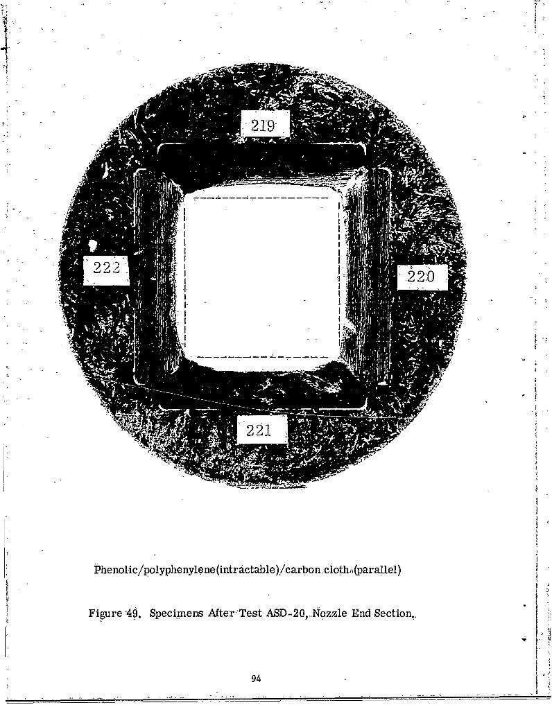
Pheni~ic'poiphenie2 (itatbe)cron9lt.(aa1l
J)
Fiur 4. peien MerTetAS-2, ozl Ed ecio.
94 2_ _ _ _ 21__ __

5191
18 9'
PhnlCcro tltpr ll
Figure,50 Spcn'isAtrT'tAD2,Cne eto.
K9

V~ -23-
A-
Fi.r 5 .ieie- fe etAD2,Mtr9d eto.
96

i1 0
Phendliic/graphite, cidth.-(parallel)
Figure 52. Specimrens Alter Test ASD-21., Noz zle EndSction.
9.7

2 3
Biphenol forrinaldehyde/car!Yo n cloth, (paralel)
'Figure 53. 'Specimens After Test ASD-21, Center-Section.
'98,

194i19
V§ 3
P~henolic/carbon cloth, (pdrallel)
- UFigur'e 54. Specimens After Tkest ASD;--21, Motor End Sectioh;
99

ir
160

UNCLASSIFIEDSecurity, Classification
(S~~tit claJg~aDOCUMENTtfle CONTROL DATAR&I. ORIGITIN G ACTIVITY, (Corporte 'iutho,) 12.RPR SKCURITV C LASSIFICATIONAtlantic Res-earch, Corporation 1UnclassifiedShirley -Highwyy at Edsall Road Iz~GROUPAlexandria-, Virginia 22314",.
3REPORT TITLE;
-Ablative, Plastic Characterization in Solid Propellanit Exhaust
4. DESCRIPTIVE- NOTES (Type,. ofm 0~thd£cfav ae) 'Summary Technical Report, 1 Julyl 1965.to 31 January 1967
S. AUTHOR(S) (Loot naie. -first-ame, 'Initial)
Batchelor., J. D'.
6. REPORT DATE' - 7f. TOTAL NO. OF PAGES Tb N.qf RE1S
April -1967 _________112
Ba. CONTRACT OR GRANT NO6. _i;.O9UtG1NATOR*S REPORTN UMIR(S)
AF 33(615)-1631&PROJECT NO.
7340? AFML TR 65-315, Part II.OTHE R %YPORT- NO($) (Any oth.nxb,.1h a.May bi assigned
4 -734001jk.,AYA&ILAOILITY4 MITATIO NOTICIES' --i ouet'i;sbjcto :special, export 'controls -an
each transmittal to foreign governments or foreign nationals .nay be made only wittthe prior approval Iof the Plastics and Composites-Branc Ih, MANC, Nonmetallic Mate-rials Div.. Air Force Matierials 'Labo s~.r~~~ht-Patterson Air-Force Base. Ohio
-1 ;:SUPPtEMENTARY HOTXS- t.SOS~N'IIAYA~VT-,v
13. ABSTRACT The purpose o -f this program was to charactedrize ablative plastics forservice in the nozzle region of solid propellini'motors. Evaluation of specimensprovided 1by the Air Force Materials Laboratory was accompl-ished by exposure Ito arealistic chemical, mechanical, aind thermal environment in a subscale, high-pvelocity motor test. This report describes the work of the final niiieteen monthsof A thirty-two month program.. The standard test method- developed in the previousyear (AFML TR 65-315) was used for 'thirteen firing tests. Based on the firsttw o these ,firings, flat laminate specim~ens were chosen as standard because
cha rae dta oul b obaind ad secienfabrication was gr tysimplified.Ithe final eleven firing tests, seventeen different resins or resin mixtures
'fomalehde)gae-sgniicrtl btte reuls tanthe sadr.Several otherresis including a chrome phenolic polyphenyl, -poyimide, and 2-7 dihy-dro-
xynahthlen pleno~fomaldhyd, sowe eihersimilar performance or promise
K ~ o eithere graphteroacarbo
fl FORMIADD I JAN64 14
Security Classification

UNCLASSIFIED-Secuity Classification ,., ',-, . . .. .. . __._ -- _ __
'- KEY'WORDS LINK A LINK 8 -LINK C"_______________________________________ OLIE WT- ROLE- WT, ROLE _WT
Plastic C6mpositesAblation
rInsulation
S61id Propellant Motors
INSTRUCTIONS.
1. ORIGINATING ACTIVITY: Enter the name end address imposed by security cssrificaiion, using standard statementsof-the contractor. subcontractor, grantee, Departmentof De- such as:fee aectivity orother-orgaition (corporst. uthor)isuing (1) "Qualified r.queaters mayiobtain.copies, of this
A e et iiprt-Iom DDWt2a. REPORT SECURMTY-CLASSIFiCATION: Enter the o.- (idl securiiy classification of the report. Indicate ihther (2) "Foregn announcement and dissemination of this-Restrict edData';7is-includid uark inito bi ac -r -report-by-DD Ist thorixed. .ance with appropriate;security regulations., (3) "U. S. Government: agencies may obtain copies of2b. GROUP: Automatic downgrading is specified In DoD-Di- this report directly from DDC. Other qualified DDC2b- RU.Atmtcdw~dn sseiidi o-i users ohall request t*4 bhrective 5200. 10 and Armed Forces Industrial ManuaL Enterthe group number. Also,-when applicable, show that optional , . . -.
- ized. • . .. ... "U. S. military agencies may obtain copies of thisized. report directly from DDC. Other- qualified user's
3. REPORT TITLE: Enter the complete report title in-all shall requeit through.capital letters. Titles in all cases should be unclassified.Ifs meaningful title cannot be selected without clasisifica- - "tin, siowtitle classification in all capitals In parenthesis (5) "All distribution of this report is controlled. Qual-immediately following the title. ified DDC users shall request through
4. DESCRIPTIVE NOTES. If appropriate, enter the type of l"- report, e.g., interim, progress, summary, annual,.or- final. 'If the'report has been furnished tc the Office of Technical,-Give the inclusive dates when a specific reportng perid is Services, Department-of Commerce, for sale to the Public, indi-covered. cate this fact and enter the price, if known.
5. AUTHOR(S): Enter the name(s) of author(s) as shown on Il. SUPPLEMENTARY'NOES: Use for adaitional explana-or in the report. Enter- last name, first name, middle Initial. tory notes.If .ilitary, -how rank end branch of service. The name ofthe principal tuthor is in absolute minimum requirement. 12. SPONSORING MILITARY ACTIVITY: Enter the name of
the departmental project office or laboratory ap6nsoring (pay-6. REPORT'DATE. Enter the date of the report as day, irg for) the research and development. Include address.month, year, or month, year. If- more than one date appears A t a b ci a an ton the report, use date of publication. 13. ABSTRACT: Enter onabstract givinga bi-f and factual
R OF P summary of the document indicative of the report, even though7a. TOTAL NUMBER OF PAGES: The total page count it may also appear elsewhere in the body of the technical re-should follow normal pagination procedures, i.e., eniter the port. If additional space Is required, a continuationsheet shallnumber of pages conteinlng information, be attached. sh
7b. NUMBER OF REFERENCER Enter the total number of It is highly desirable that the p,satract of classified reportsreferences cited in the report. 'be unclassified. Each paragraph of the abstract shall end with
'3a. CONTRACT OR GRANT NUMBER: If appropriate, enter i n indication of the military security classification of the in-the applicable number of the contract or grant under which formation inthe paragraph, represented as (Ts). (S), (C), or (U).,the report was WYritten,. 'There is no limitation cn the length of the abstract. How-
8b, Sc, & 8d. PROJECT NUMBER Enter the appropriate ever, the suggested length is from 150 to 225 words.military department identification such as project number, 14. KEY WORDS: Key words are technically meaningful terms14.rec KEYer WORDS: nuberss tase techncar, meatnfu tem-subprojict number, system numbers, task number, etc. - or short phrases that characterize a report and may be used as9a. ORIGINATOR'S REPORT NUMBER(S): Enter the offi- index entries for cataloging the report. Key words must becial report number by which the document will be identified selected so that no security classification is ,equired. Identi-and c'ntrolled by the originating activity. This number must fiers, such, asequipment model designation, trade name, militarybe unque to this report. project code name, geographic location, may be used os-key9b, OTHER REPORT NUMBER(S): If the report has been words but will be followed by an indication of technical con-assignedRany other report numbers (either by the originator text. The assignment oflinks, rules, and weights is optional.
-or by-ehe sponsor); also enter this~number(s),
10. -AVAILABILITX/LIMITATiON-NOTICES Enter any lim-it stions;zn further dissemination of, the re-ort, other than those-
U-NCLASSIFIED,$ $ecurity Classification,