tomotherapy - american association of physicists in medicineclinical implications • more complex...
TRANSCRIPT

Thomas Rockwell MackieTomotherapy Research GroupDepts. Of Medical Physics, Human Oncology
and Biomedical EngineeringUniversity of WisconsinMadison WI 53706Phone: (608) 262-7358Email: [email protected]: www.madrad.radiology.wisc.edu
Tomotherapy

Contributors to this Talk
• Gustavo Olivera• Paul Reckwerdt• Jeff Kapatoes• Ken Ruchala• John Balog• Richard Schmidt• Ed Fitchard• Dave Pearson• Eric Schloesser• Ray MacDonald
• Robert Jeraj• Minesh Mehta• Mark Ritter• Jack Fowler• Harry Keller• Weiguo Lu• Jeni Smilowitz• Wolfgang Tomé• Rufus Scrimger• Lisa Forrest

Financial Disclosure
In addition to a University of Wisconsin Professor, I am a co-founder of TomoTherapy Inc. (Middleton WI) which is participating in the commercial development of helical tomotherapy.
www.tomotherapy.com
TomoTherapy’s1,400 m2
Middleton facility.

Outline
• Optimization Æ IMRT Æ Conformal Dose Distributions• Sequential (or Serial) Tomotherapy (NOMOS Peacock™)• Clinical Helical Tomotherapy Unit• Dosimetry of Helical Tomotherapy• Examples of Tomotherapy Dose Distributions• Megavoltage Computed Tomography (MVCT)• Adaptive Radiotherapy • Clinical Implications
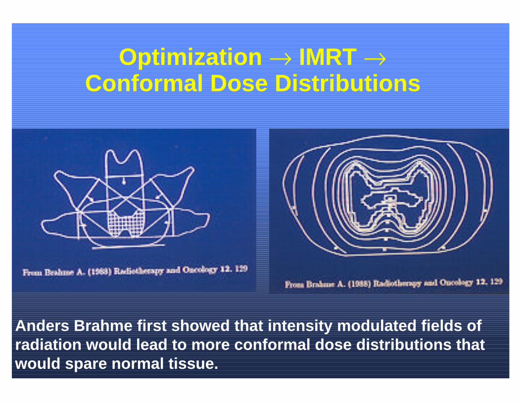
Optimization Æ IMRT ÆConformal Dose Distributions
Anders Brahme first showed that intensity modulated fields of radiation would lead to more conformal dose distributions thatwould spare normal tissue.

IMRT Using Conventional MLC’s
Varian
Siemens
Elekta
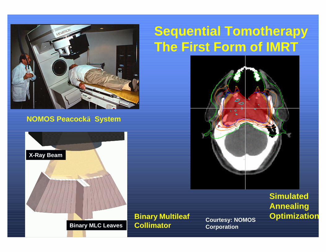
NOMOS Peacock System
SimulatedAnnealingOptimizationCourtesy: NOMOS
Corporation
X-Ray Beam
Binary MLC Leaves Binary MultileafCollimator
Sequential TomotherapyThe First Form of IMRT

MIMiCMIMiC
MMultileafultileafIIntensity ntensity MModulatodulatiingngCCollimatorollimator
Individual leaf Individual leaf controls openingcontrols opening
From Bruce Curran, NOMOS

3D-CRTBi-Lateral
60 Gy
50 Gy
30 Gy
68 Gy
From Bruce Curran, NOMOS

Sequential Tomotherapy (Nomos Peacock)
7-Field IMRT(Planned with Corvus)
85Gy
70Gy
60Gy
50Gy
30Gy
From Bruce Curran, NOMOS
1008060402000
20
40
60
80
100
120
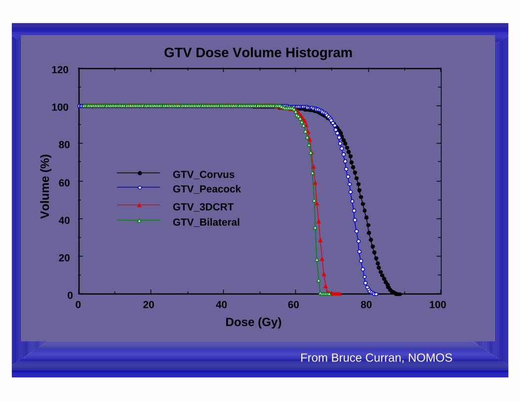
GTV_CorvusGTV_Peacock
GTV_3DCRTGTV_Bilateral
GTV Dose Volume Histogram
Dose (Gy)
Vo
lum
e (%
)
From Bruce Curran, NOMOS
1201008060402000
20
40
60
80
100
120
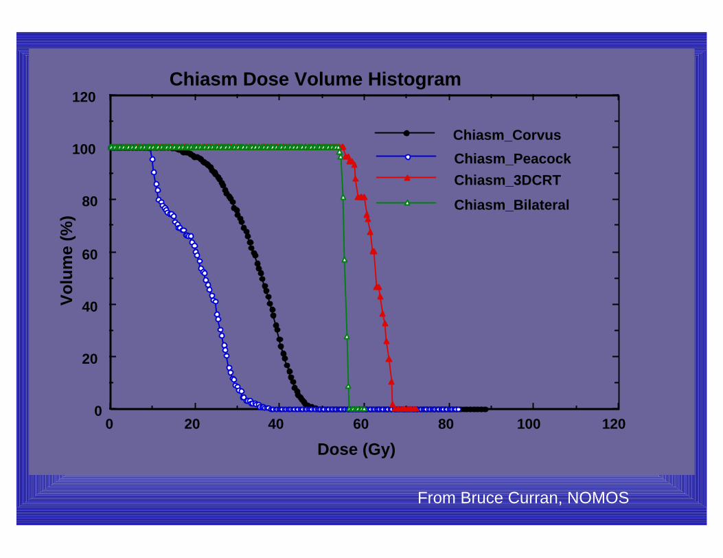
Chiasm_Corvus
Chiasm_PeacockChiasm_3DCRT
Chiasm_Bilateral
Chiasm Dose Volume Histogram
Dose (Gy)
Vo
lum
e (%
)
From Bruce Curran, NOMOS

1008060402000
20
40
60
80
100
120
Stem_CorvusStem_Peacock
Stem_3DCRT
Stem_Bilateral
Brain stem Dose Volume Histogram
Dose (Gy)
Vo
lum
e (%
)
From Bruce Curran, NOMOS

1008060402000
20
40
60
80
100
120
Parotid_CorvusParotid_Peacock
Parotid _3DCRTParotid_Bilateral
Parotid Dose Volume Histogram
Dose (Gy)
Vo
lum
e (%
)
From Bruce Curran, NOMOS
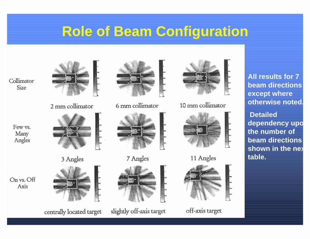
Role of Beam Configuration
All results for 7 beam directions except where otherwise noted.
Detailed dependency upon the number of beam directions is shown in the next table.

Dependency Upon Number of Beam Directions
25440.1550.9330.0380.15133
25450.1710.9120.0490.17621
25420.1800.9080.0530.18715
25700.1860.8790.0580.20211
25990.1920.8550.0640.2229
25970.2060.8670.0640.2427
25640.2150.8140.0900.3185
27330.4880.7470.1240.6653
Total Integral Dose
Mean Dose to the Region at Risk
Minimum Dose Covering 90% of the Target (1.0=max)
Standard Deviation in the Target Dose
Objective Function Value
Number of Beam Directions

Nasopharyngeal Example
In this case the primary goal was to avoid the parotid and spinal cord. With the same amount of avoidance, the 45 angle delivery (tomotherapy) provided a more homogeneous delivery.

Re-Engineering Radiotherapy
• Equipment and processes re-engineered for IMRT• Integration of planning, delivery and verification• Better leaf resolution• Simple MLC’s• More beam directions• Single energy photon beam• Better primary shielding• Tomographic verification• Helical tomotherapy was the result

HelicalScanning
Helical (Spiral) Tomotherapy
Helical Fan Beam
Ring Gantry
Linac
CT Detector
CT Couch

Animation of Helical Delivery

64 Leaf Binary MLC
Close-Up

Movie Clips of the MLC Being Tested
Close-Up

UW Clinical Helical Tomotherapy Unit
Siemens Linac
GE CTDetector
SiemensRF System
May 2000 at UW Physical Sciences Laboratory, Stoughton WI
GE Gantry

Siemens 6 MV Linac System
Linac and Gun Control
RF System

Clinical Installation Finished
January 16, 2001 at UW Radiotherapy Clinic

Major Specifications
• 6 MV Siemens linac • Up to 8 Gy/min @ axis• 85 cm diameter gantry bore• 64 leaves with 6.25 mm resolution @ axis• 4 cm x 40 cm maximum field @ axis• Slice field width from 5 mm to 40 mm @ axis• Minimum beamlet size 5 mm x 6.25 mm @ axis• Xenon CT detectors with per pulse acquisition• 0.25 mm precision CT couch• Leaves 10 cm thick, 95% tungsten alloy• Primary collimator 22 cm thick 95% tungsten alloy

Fan Beam Characteristics• The fan field width along the longitudinal
direction is continuous from 5 mm to 50 mm.• There is no field flattening filter in the beam
and so the beam has a higher intensity along the center as compared to either end.
• The beam without filtration is like the output from a CT “Bowtie Filter”.
40 cm
1 cmImage Digitized from Kodak XV Film

Profile Along Length of a 1 cm Wide Fan Beam
Transverse Profile
0
20
40
60
80
100
120
-240 -180 -120 -60 0 60 120 180 240Distance (mm)
Do
se (
%)

Monte Carlo Model of the Treatment HeadTarget
Electron Stopper
Monitor Chamber
Primary Collimatorand Jaws
Electron Beamfrom the Accelerator Beam Hardener

Photon Spectrum
For the same incident energy, tomotherapy has a harder spectrum due to its beam hardener and absence of a field flattening filter.
0 1 2 3 4 5 60.0
0.2
0.4
0.6
0.8
1.0
Tomotherapy (6MV) 2100 Clinac (6MV, Stanford)
Spe
ctru
m [%
]
Energy [MeV]
Clinac 2100Monte Carlodata courtesy ofDr. Charlie Ma

Off-Axis Energy Dependence
0 1 2 3 4 5 6 70.000
0.005
0.010
0.015
0.020
0.025
0.030
0.035
0.040
0-5 cm 5-10 cm 10-15 cm 15-20 cm
Pho
ton
spec
trum
Energy [MeV]
0 1 2 3 4 5 6
1E-3
0.01
0-5 cm 5-10 cm 10-15 cm 15-20 cm
Pho
ton
spec
trum
Energy [MeV]
Tomotherapy has no off axis hardening because of no flattening filter.
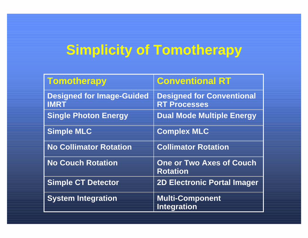
Simplicity of Tomotherapy
Multi-Component Integration
System Integration
2D Electronic Portal ImagerSimple CT Detector
One or Two Axes of Couch Rotation
No Couch Rotation
Collimator RotationNo Collimator Rotation
Complex MLCSimple MLC
Dual Mode Multiple EnergySingle Photon Energy
Designed for Conventional RT Processes
Designed for Image-Guided IMRT
Conventional RTTomotherapy

Conventional Plan to Treat Lung Cancer
Spinal Cord
Tumor
20 %98 % 70 % 50 % 40 %

Tomotherapy Plan to Treat Lung Cancer
20 %80 % 70 % 50 % 40 %
Spinal Cord
Tumor
0
5
10
15
20
25
P1 P2 P3 P4 P5 Mean
Patient
3D plans
Tomotherapy
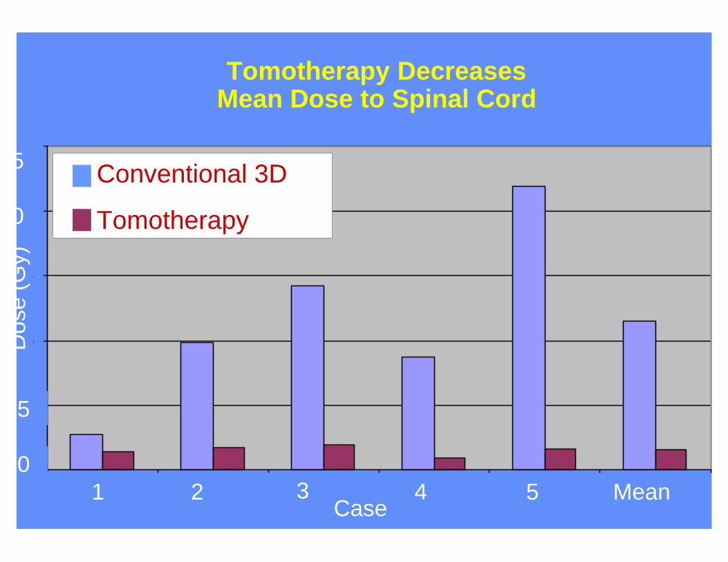
Case
Tomotherapy DecreasesMean Dose to Spinal Cord
Conventional 3D
Tomotherapy
1 5432 Mean
Dos
e (G
y)
5
0
20
25
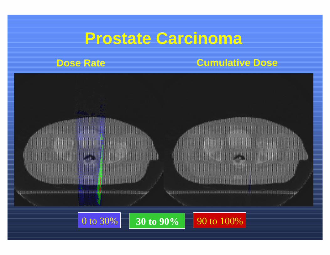
Prostate CarcinomaDose Rate Cumulative Dose
0 to 30% 30 to 90% 90 to 100%

Percentage of Rectal Volume Receiving High Doses
% of volume exceeding stated dose
0
5
10
15
20
25
Conventional 3D Tomotherapy
>60 Gy>70 Gy
Conventional 3D Tomotherapy

ROI slice 47
Breast Carcinoma Case:Tomotherapy MovieDose Rate Cumulative Dose
Tumor
IMC nodesContr.breast
Leftlung
Rightlung
Heart
Spine
0 to 30% 30 to 90% 90% or higher

Tomotherapy for GBM Treatments
Isodose Lines
100%90%80%50%
Targets
GTV
Hypoxic
Proliferative

Tomotherapy for GBM TreatmentsDose Rate Cumulative Dose
50 to 75% 75 to 85 % 95 to 100%85 to 95 %0 to 50 %

Dose Rate Cumulative Dose
ROI slice 27
Mesothelioma

Slice 27 Slice 31 Slice 36
50 %80 %90 %
50 %80 %90 %
50 %80 %90 %
Tomotherapy Dose Distributions


Adaptive Radiotherapy3-D Imaging
OptimizedPlanning
MV CT+ Image Fusion
TreatmentWith DeliveryVerification
DoseReconstruction
DeliveryModification
DeformableDose
Registration

Why CT Before Delivery is Necessary
The slices were rotated and translated to alignthe bony anatomy asbest as possible.
Courtesy Di Yanand Marcel Van Herk
Original CTV
CT Images Acquired Daily

Interfraction Movement of the Breast
From Dr. Jason SohnMallinckrodtInstitute
Electronicportal imageof the breasttreated using a compensator.Each frame is adifferent day.

MVCT of CIRS Phantom
7 cGy 3.5 cGy 1.75 cGy
11.7%
51.2%-81.0%
-4.8%
-54.1%
4.3%0.2%
-2.4%
5.2%

MVCT of RMI Phantom
1.50 mm1.25 mm1.00 mm0.8 mm
1.50 mm1.25 mm1.00 mm0.8 mm

MVCT Calibration Curve
ImageDensity
Electron density (red), physical density (violet)

Rando Phantom Megavoltage CT (MVCT)
Head Pelvis
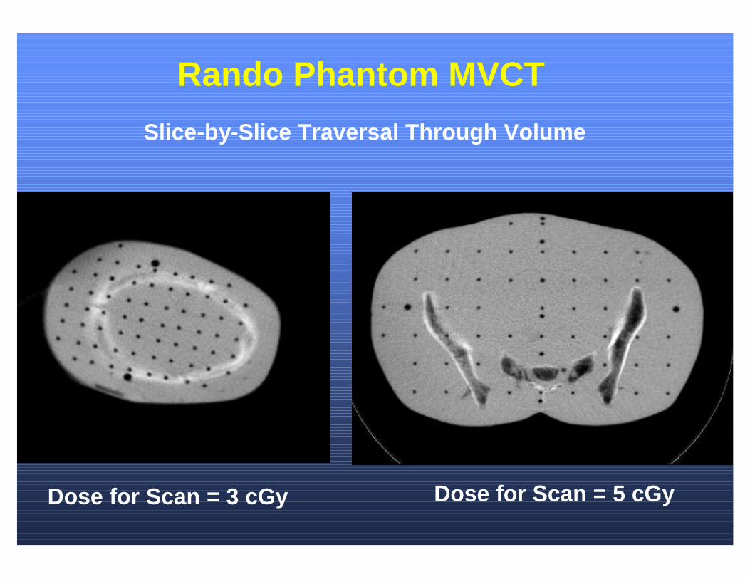
Rando Phantom MVCT
Slice-by-Slice Traversal Through Volume
Dose for Scan = 3 cGy Dose for Scan = 5 cGy

Automated Fusion of kV and MV CT Sets

Fusing Prostate CT’s Acquired on Two Different Days
X-offset= 4.20 cm
Y-offset= 4.20 cm
Z-offset= 2.60 cm
Roll-offset= 32.50 deg
Pitch- offset= 8.90 deg
Yaw- offset= 14.70 deg

Adaptive Radiotherapy3-D Imaging
OptimizedPlanning
MV CT+ Image Fusion
Helical Tomotherapy
DoseReconstruction
DeliveryModification
DeformableDose
Registration

Delivery Modification
• There are two potential ways to adjust the patient setup:– Adjust the patient. – Adjust the beams.
• It may be easier and more reliable to move the beams to the patient.
• It may be possible in tomotherapy to alter the leaf delivery pattern.

50 %80 %95 %
50 %80 %95 %
Optimized
DeliveryModified
1.42 cm offset
1cm x-offset
1cm y-offset

Adaptive Radiotherapy3-D Imaging
OptimizedPlanning
MV CT+ Image Fusion
Helical Tomotherapy
DoseReconstruction
DeliveryModification
DeformableDose
Registration

Dose Reconstruction
• Dose reconstruction uses transmission data acquired during treatment and the megavoltage CT to determine the dose distribution delivered that day.
• Dose reconstruction provides a way to directly compare the plan with the result.

Target
R. eye
L. eye
Brain
Example of Dose ReconstructionROI’s (slice 29) MV CT (slice 29)
8.5 deg. Shift

Dose Reconstructed Using MV CT
OptimizedReconstructed
The reconstructed dose reveals that the dose distribution is rotated toward the left eye and underdosing the target volume.

Adaptive Radiotherapy3-D Imaging
OptimizedPlanning
MV CT+ Image Fusion
Helical Tomotherapy
DoseReconstruction
DeliveryModification
DeformableDose
Registration

Deformable Dose Registration
• Deformable dose registration uses a mechanical deformation model along with matched contours and points from two image sets to register them.
• Deformable dose registration allows the dose from each fraction to be added up properly.


Adaptive Radiotherapy3-D Imaging
OptimizedPlanning
MV CT+ Image Fusion
Helical Tomotherapy
DoseReconstruction
DeliveryModification
DeformableDose
Registration

Adapted Dose DistributionImage of Regret
9 to 12 mm(%)3 to 6 mm(%)
6 to 9 mm(%)0 to 3 mm(%)
Dose to deliver to correct regret.

Incorrect +Perfect
9 to 12 mm(%)3 to 6 mm(%)
6 to 9 mm(%)0 to 3 mm(%)
9 to 12 mm(%)3 to 6 mm(%)
6 to 9 mm(%)0 to 3 mm(%)
Non - Adapted Adapted
Incorrect +Corrected

Clinical Implications
• More complex target volumes can be delivered and still spare critical volumes.
• Complex prescriptions or “dose painting”.• Higher dose/fraction can be delivered to the tumor and
still have low dose and dose/fraction to critical tissues. • Conformal avoidance.• More accurate setup of the patient.• Better verification that delivery is correct.• Have a basis to repair dose distributions.• Adaptive radiotherapy.

Other Innovative Treatments Tomotherapy Will Enable
• Stereotactic radiotherapy (and radiosurgery) to the body.• Irradiate entire nodal chains with conformal avoidance.• Repairing the dose distributions from other modalities, e.g.,
poor seed implants.• Combined brachytherapy and IMRT.• Bone marrow ablation while sparing visceral organs.• Whole-skin irradiation using IMRT.• Probability-based prophylactic radiotherapy.• Swiss-cheese-like dose distributions in normal tissue (3-D
grid therapy).• Great change in breast radiotherapy.

Increased Throughput Possible
• Integration of planning, delivery and verification.• Potentially easier to commission and calibrate.• Dose reconstruction eliminates need for on-going patient-specific
dosimetry measurements.• Fewer planning decisions and optimization may be automated.• High dose rate (8 Gy/min).• Higher dose/fraction more feasible because normal tissue can be
more easily avoided.• Easier patient setup.• No couch rotation reducing possibility of collision.• Tomographic verification images are more easy to interpret than
planar portal images.• Impact of delivery errors can be reduced.• Increased primary collimation so less staff irradiation per patient.

Conclusions
• Helical tomotherapy is the marriage of a linac with a CT scanner.
• Helical tomotherapy can deliver highly conformal dose distributions.
• Megavoltage CT is sufficient for verification of the setup.• Dose reconstruction and deformable registration
determines the dose actually delivered.• Adaptive radiotherapy ensures that the whole course of
therapy is delivered correctly.• Tomotherapy provides image-guidance for the whole
chain of radiotherapy processes.