towbar fitting instructions to suit mitsubishi asx 2010- on … · towbar fitting instructions to...
TRANSCRIPT
Towbar Fitting InstructionsTo Suit MITSUBISHI ASX 2010- on
Part Number QTCL649LRating 1400 kg
PLACE THESE INSTRUCTIONS IN THE VEHICLE’S GLOVEBOX AFTER INSTALLATION IS COMPLETE
Page 1 of 3 Issue Date 12-06-12Cequent Customer Service
Ph: 1800 812 017 Fax: 03 9898 3299 Email: [email protected]
Post: PO Box 4050, Dandenong South VIC 3175
FOR TRAILER TOWING PURPOSES ONLY For towing capacity details please refer to vehicle owner’s manual or to the manufacturer. Overloading can void your warranties.
WARNING:1. Do not, drill, cut, weld or otherwise modify the tow bar. 2. If you are using electric welding on a motor vehicle, always check that the vehicle is not equipped with electronic
engine or instrument management equipment. Failure to do so could destroy any onboard computers. If in doubt, check with the vehicle's manufacturer.
3. The high tensile fasteners supplied with this product were used to achieve the specified rating. If replacement is required ensure that fasteners of the same rating & quality are used. Contact an authorised Trailboss dealer if further information is required.
General:1. Ensure all hardware items have been included refer to assembly diagram. 2. It is recommended that the instructions are read through and completely understood before making any attempt
to fit this product. 3. Be wary of any changes to vehicle designs or other accessories that may conflict with the installation of this
product. 4. Before drilling ensure that the area is clear of fuel, electrical & other components. 5. All holes drilled into the body panels shall have all burrs & swarf removed then coated with a suitable rust
preventative paint. 6. For vehicles that require the bumper to be cut. Ensure cut out area is in correct position on the vehicle prior to
cutting the bumper. 7. The high tensile fasteners supplied with this product were used to achieve the specified rating. If replacement is
required ensure that fasteners of the same rating & quality are used. Contact an authorized Trailboss dealer if further information is required.
8. Ensure that all hardware is fastened to torque list below check fasteners on regular basis. 9. Tow bar load rating sticker provided with this product shall be conspicuously located on inside rear end of the
driver's door. (See diagram below).10. Trailboss recommends that you check your tow ball to ensure that it complies with the Australian standards
AS 4177.2.11. PLEASE NOTE: It is advised to remove your lug or tbm when not actually towing so as to produce a clear view of
the vehicles registration plate if obscured, and to also provide maximum available departure angle 12. Pull Pin must be fit in down position.
Tow bar Maintenance and Care.
Trailboss recommends that bolt torque’s, as listed below, are routinely and regularly inspected and checked for correct tension. Replace any worn or defective parts. We recommended to remove Tow Ball Mounts (TBM’s, tongues or lugs) when not being used for any considerable length of time.So as to avoid injury, when not towing it is suggested that the tongue, Pull Pin and R-clip are removed then stored in a safe, clean and dry place, away from excessive moisture. Hitch Pull Pins and spring “R” clips are regularly checked for proper installation. Replace any worn or defective parts.
Place load rating sticker inside driver’s door here
RECOMMENDED ASSEMBLY TORQUE LISTING Diameter Grade 8.8 Bolt
mN 5.9 6M mN 7.12 8M mN 4.34 01M
mN3.77 21M mN 641 41M mN 8.98161M
Rev : A

Towbar Fitting InstructionsTo Suit MITSUBISHI ASX 2010- on
Part Number QTCL649LRating 1400 kg
PLACE THESE INSTRUCTIONS IN THE VEHICLE’S GLOVEBOX AFTER INSTALLATION IS COMPLETE
Page 2 of 3 Issue Date 29-05-15Cequent Customer Service
Ph: 1800 812 017 Fax: 03 9898 3299 Email: [email protected]
Post: PO Box 4050, Dandenong South VIC 3175
QTY. DESCRIPTION ITEM NO
1 WELD ASSY MITSUBISHI ASX 1
2 TBM 1
8 S/WSHR M10 X 3.5 X 2.2 3
12 WASHER PLAIN M10 X 25 X 3 4
5 NUT HEX HD M10 X 1.5P 5
1 BOLT HEX HD M10 X 25 X 1.5P 6
4 SETSCREW HXHD M10X35X1.25 7
4 BOLT HEX HD M10 X 120 X 1.5P 8
Rev : B
Towbar Fitting InstructionsTo Suit MITSUBISHI ASX 2010- on
Part Number QTCL649LRating 1400 kg
PLACE THESE INSTRUCTIONS IN THE VEHICLE’S GLOVEBOX AFTER INSTALLATION IS COMPLETE
Page 3 of 3 Issue Date 29-05-15Cequent Customer Service
Ph: 1800 812 017 Fax: 03 9898 3299 Email: [email protected]
Post: PO Box 4050, Dandenong South VIC 3175
1. Remove rear tail lights Via a. Remove 2 x Screws from each side. b. Remove the tail light, Push it rearwards, some force may be required. Store them in a safe place.
2. Remove Rear Bumper Bar Skin Via a. Remove 4 x M5 Screws from each side of the bar cavity. b. Remove 2 x Screws and 2 Scrivets from inside the wheel arch on both sides. c. Remove 1 Screw from outside the wheel Arch on both sides. d. Remove 2 Scrivets from under the Bumper. e. Flex Bumper cut at the sides then pull rearwards to remove, some force may be required.Store the Bumper in
a safe location. CAUTION –TWO PERSON LIFT REQUIRED
3. Preparation before Towbar Fitment a. Remove 3 Screws from each side of the impact beam and discard it. b. Remove 3 x M10 Screws holding the shipping hook and discard it as well.
4. Fitment of Towbar Via a. Lower the exhaust Via 2 x rubber hangers to gain better access. b. Fit the Towbar using 4 x M10 x 120 mm on both sides with Flat Washer and nuts ; Use 4 x M10 x 35mm with
spring Washer and flat Washer to the captive nuts and the chassis. See Assembly drawing in page2 . c. Torque all fasteners to specification.
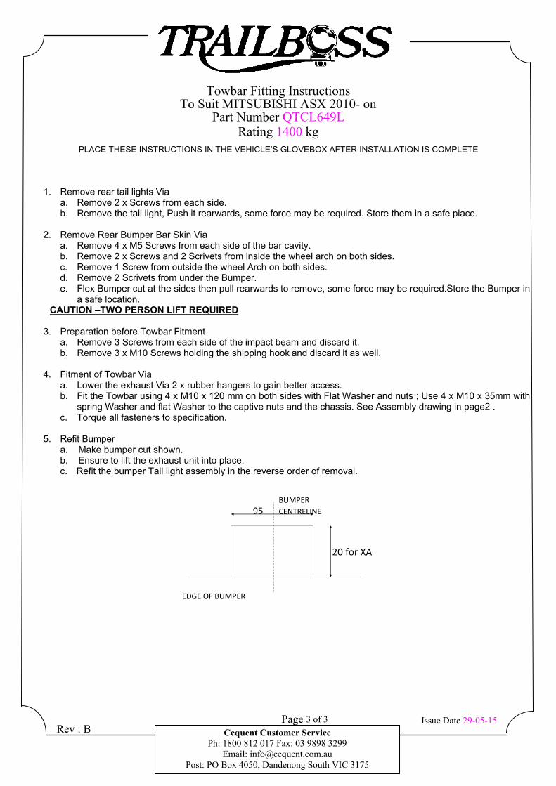
5. Refit Bumper a. Make bumper cut shown. b. Ensure to lift the exhaust unit into place. c. Refit the bumper Tail light assembly in the reverse order of removal.
Rev : B
20 for XA
BUMPER
CENTRELINE95
EDGE OF BUMPER
Wiring Loom Fitting InstructionsTo Suit Mitsubishi ASXPart Number 100476-WL
Page 1 of 3 Issue Date 27-09-10
Cequent Customer ServicePh: 1800 812 017 Fax: 03 9797 3299
Email: [email protected]: PO Box 4050, Dandenong South VIC 3175
Wiring Loom Installation Instructions
Mitsubishi ASXPart No: 100476-WL
ECU: 04826
Tail Harness Length Required: 1200mmRPA Override Switch Part No: 04848 (If Fitted)
Wiring Loom Installation Time: Approx 30 Mins

Wiring Loom Fitting Instructions To Suit Mitsubishi ASX Part Number 100476-WL
Page 2 of 3 Issue Date 27-09-10 Cequent Customer Service
Ph: 1800 812 017 Fax: 03 9797 3299 Email: [email protected]
Post: PO Box 4050, Dandenong South VIC 3175
1. In the engine bay, locate the vehicle battery.
2. Locate the engine bay 4-way breakout connector in the front LHS of the engine bay.
3. Remove the blanking cap from the connector.
4. Connect the 4-way breakout connector to the engine bay power loom mating connector.
5. Connect the engine bay power loom ground ring terminal to the vehicle battery positive terminal.
6. In the luggage compartment, remove the floor cover carpet and parcel shelf.
7. Fold the rear seats forwards.
8. Remove the rear trim by first removing the two clips.
9. Remove the rear seat carpet guard by first removing the two clips.
10. Remove the LHS & RHS tool storage trays.
11. Inside the vehicle cabin, remove the rear seat cushion.
12. Remove the RHS rear scuff plate.
13. In the luggage compartment, remove the two fasteners from the cargo tie down hooks
14. Remove the cargo tie down hooks.
15. Remove the RHS light and disconnect the connector. Note: The following steps are for vehicles fitted with a factory subwoofer only, otherwise please proceed to Step 19. 16. Remove the factory subwoofer, by first removing the five 10mm bolts.
17. Disconnect the subwoofer connector.
18. Remove the factory subwoofer.
19. Locate the vehicle 12-way female breakout connector on the RHS of the luggage compartment.
20. Patch in the trailer patch (P/No: 100476-WL) mating connector.
21. From outside the vehicle, drill a Ø31mm hole on the underside of the RHS rear corner of the vehicle.
22. File any rough or sharp edges and spray on rust inhibitor.
23. Connect the trailer harness 12-way connector to the ECU.
24. Apply double sided tape to the ECU and adhere it to the outward face of the inner sheet metal on the
RHS of the luggage compartment.
Wiring Loom Fitting Instructions To Suit Mitsubishi ASX Part Number 100476-WL
Page 3 of 3 Issue Date 27-09-10 Cequent Customer Service
Ph: 1800 812 017 Fax: 03 9797 3299 Email: [email protected]
Post: PO Box 4050, Dandenong South VIC 3175
25. Connect the trailer harness ground ring terminal to the vehicle grounding point.
26. Mount the trailer socket to the towbar mounting bracket using M4 fasteners (not supplied).
27. Route the tail harness across the towbar towards the RHS of the vehicle and up through the previously drilled out hole.
28. Ensure the tail harness grommet is seated correctly and secure in place using a cable tie (not supplied).
29. Connect the tail harness (tail length 1200mm) 8-way connector to the trailer harness mating 8-way
connector.
30. Test the Trailer socket using a light board or multi-meter.
31. Secure the all harnesses using cables ties (not supplied).
32. Re-fit all removed parts and secure all fasteners.
33. Place instructions in glove box after fitment.
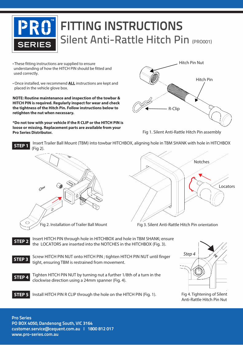
FITTING INSTRUCTIONSSilent Anti-Rattle Hitch Pin (PRO001)
Pro SeriesPO BOX 4050, Dandenong South, VIC 3164 [email protected] I 1800 812 017 www.pro-series.com.au
• These fitting instructions are supplied to ensureunderstanding of how the HITCH PIN should be fitted andused correctly.
• Once installed, we recommend ALL instructions are kept andplaced in the vehicle glove box.
NOTE: Routine maintenance and inspection of the towbar & HITCH PIN is required. Regularly inspect for wear and check the tightness of the Hitch Pin. Follow instructions below to retighten the nut when necessary.
*Do not tow with your vehicle if the R CLIP or the HITCH PIN isloose or missing. Replacement parts are available from your Pro Series Distributor.
Hitch Pin Nut
R-Clip
Hitch Pin
Fig 1. Silent Anti-Rattle Hitch Pin assembly
Fig 2. Installation of Trailer Ball Mount Fig 3. Silent Anti-Rattle Hitch Pin orientation
Insert Trailer Ball Mount (TBM) into towbar HITCHBOX, aligning hole in TBM SHANK with hole in HITCHBOX (Fig 2).
Insert HITCH PIN through hole in HITCHBOX and hole in TBM SHANK; ensure the LOCATORS are inserted into the NOTCHES in the HITCHBOX (Fig. 3).
STEP 1
STEP 2
Screw HITCH PIN NUT onto HITCH PIN ; tighten HITCH PIN NUT until fingerSTEP STEP 3 3 tight, ensuring TBM is restrained from movement.
Tighten HITCH PIN NUT by turning nut a further 1/8th of a turn in the clockwise direction using a 24mm spanner (Fig. 4).
STEP 4
Install HITCH PIN R CLIP through the hole on the HITCH PIN (Fig. 1). STEP 5
Step 4
Fig 4. Tightening of Silent Anti-Rattle Hitch Pin Nut
Notches
Locators
STEP 3