tr 101 953-2-3 - v1.1.1 - access network xdsl transmission filters… · access network xdsl...
TRANSCRIPT

ETSI TR 101 953-2-3 V1.1.1 (2004-07)
Technical Report
Access network xDSL transmission filters;Part 2: VDSL splitters for European deployment;
Sub-part 3: Specification of Testing methodsfor VDSL/ISDN splitters

ETSI
ETSI TR 101 953-2-3 V1.1.1 (2004-07) 2
Reference DTR/TM-06027-2-3
Keywords ADSL, ISDN, POTS, VDSL, splitter, testing, xDSL
ETSI
650 Route des Lucioles F-06921 Sophia Antipolis Cedex - FRANCE
Tel.: +33 4 92 94 42 00 Fax: +33 4 93 65 47 16
Siret N° 348 623 562 00017 - NAF 742 C
Association à but non lucratif enregistrée à la Sous-Préfecture de Grasse (06) N° 7803/88
Important notice
Individual copies of the present document can be downloaded from: http://www.etsi.org
The present document may be made available in more than one electronic version or in print. In any case of existing or perceived difference in contents between such versions, the reference version is the Portable Document Format (PDF).
In case of dispute, the reference shall be the printing on ETSI printers of the PDF version kept on a specific network drive within ETSI Secretariat.
Users of the present document should be aware that the document may be subject to revision or change of status. Information on the current status of this and other ETSI documents is available at
http://portal.etsi.org/tb/status/status.asp
If you find errors in the present document, send your comment to: [email protected]
Copyright Notification
No part may be reproduced except as authorized by written permission. The copyright and the foregoing restriction extend to reproduction in all media.
© European Telecommunications Standards Institute 2004.
All rights reserved.
DECTTM, PLUGTESTSTM and UMTSTM are Trade Marks of ETSI registered for the benefit of its Members. TIPHONTM and the TIPHON logo are Trade Marks currently being registered by ETSI for the benefit of its Members. 3GPPTM is a Trade Mark of ETSI registered for the benefit of its Members and of the 3GPP Organizational Partners.

ETSI
ETSI TR 101 953-2-3 V1.1.1 (2004-07) 3
Contents
Intellectual Property Rights ................................................................................................................................4
Foreword.............................................................................................................................................................4
1 Scope ........................................................................................................................................................5
2 References ................................................................................................................................................5
3 Definitions and abbreviations...................................................................................................................5 3.1 Definitions..........................................................................................................................................................5 3.2 Abbreviations .....................................................................................................................................................5
4 Introduction ..............................................................................................................................................6
5 Test conditions and general notes ............................................................................................................6
6 Test cases for VDSL over ISDN-BA splitters..........................................................................................8 6.1 Insertion loss in the pass band (ISDN-BA) ........................................................................................................9 6.2 Return loss in the pass band (ISDN-BA)..........................................................................................................11 6.3 Delay distortion in the pass band (ISDN-BA)..................................................................................................13 6.4 Isolation (insertion loss) at 150 kHz to 12 MHz...............................................................................................15 6.5 Unbalance about earth ......................................................................................................................................18 6.6 Unbalance about earth without DC feeding......................................................................................................18 6.7 Unbalance about earth with DC feeding...........................................................................................................20 6.8 Noise ................................................................................................................................................................20 6.9 DC requirements ..............................................................................................................................................22 6.9.1 DC resistance to earth .................................................................................................................................22 6.9.2 Isolation resistance between A-wire and B-wire ........................................................................................24 6.9.3 DC series resistance ....................................................................................................................................26 6.10 Insertion loss requirements for the high pass part ............................................................................................27
History ..............................................................................................................................................................30

ETSI
ETSI TR 101 953-2-3 V1.1.1 (2004-07) 4
Intellectual Property Rights IPRs essential or potentially essential to the present document may have been declared to ETSI. The information pertaining to these essential IPRs, if any, is publicly available for ETSI members and non-members, and can be found in ETSI SR 000 314: "Intellectual Property Rights (IPRs); Essential, or potentially Essential, IPRs notified to ETSI in respect of ETSI standards", which is available from the ETSI Secretariat. Latest updates are available on the ETSI Web server (http://webapp.etsi.org/IPR/home.asp).
Pursuant to the ETSI IPR Policy, no investigation, including IPR searches, has been carried out by ETSI. No guarantee can be given as to the existence of other IPRs not referenced in ETSI SR 000 314 (or the updates on the ETSI Web server) which are, or may be, or may become, essential to the present document.
Foreword This Technical Report (TR) has been produced by ETSI Technical Committee Transmission and Multiplexing (TM) as collaboration between:
• AT Analogue of Technical Committee Access and Terminals (AT); and
• TM6 of Technical Committee Transmission and Multiplexing (TM).
The present document is part 2, sub-part 3 of a multi-part deliverable supporting different aspects of European Specific DSL splitters, as identified below:
Part 1: "ADSL splitters for European deployment";
Part 2: "VDSL splitters for European deployment":
Sub-part 1: "Specification of Testing methods for the low pass part of VDSL/POTS splitters";
Sub-part 2: "Specification of Testing methods for high pass part of VDSL/POTS splitter";
Sub-part 3: "Specification of Testing methods for VDSL/ISDN splitters".
NOTE: The choice of a multi-part format for this deliverable is to facilitate maintenance and future enhancements.
ETSI
ETSI TR 101 953-2-3 V1.1.1 (2004-07) 5
1 Scope The present document describes test methods for VDSL/ISDN splitters. These splitters are intended to be installed at the Local Exchange side of the local loop and at the user side near the NTP. In the case of splitters at the user side, the present document describes testing methods for the master splitter that is intended for use at the demarcation point of the customer premises.
NOTE 1: At some locations in the present document impedances values are listed. These values might differ from the values listed in the requirement specifications TS 101 952-2-3 [1]. If the values differ the values of TS 101 952-2-3 [1] have to be used.
NOTE 2: At some locations in the present document measurements are only shown for splitters at the user side. E.g. this is the case in figure 5. When measuring a splitter at the Local Exchange side the position of the Feeding bridge and the Holding Circuit have to be exchanged.
2 References For the purposes of this Technical Report (TR) the following references apply:
[1] ETSI TS 101 952-2-3: "Access network xDSL transmission filters; Part 2: VDSL splitters for European deployment; Sub-part 3: Specification of VDSL/ISDN splitters for use at the Local Exchange (LE) and the user side near the Network Termination Point (NTP)".
[2] ETSI TS 101 270-1: "Transmission and Multiplexing (TM); Access transmission systems on metallic access cables; Very high speed Digital Subscriber Line (VDSL); Part 1: Functional requirements".
[3] ETSI TS 102 080: "Transmission and Multiplexing (TM); Integrated Services Digital Network (ISDN) basic rate access; Digital transmission system on metallic local lines".
[4] ETSI TBR 038: "Public Switched Telephone Network (PSTN); Attachment requirements for a terminal equipment incorporating an analogue handset function capable of supporting the justified case service when connected to the analogue interface of the PSTN in Europe".
[5] ITU-T Recommendation O.9: "Measuring arrangements to assess the degree of unbalance about earth".
[6] ETSI TR 102 139: "Compatibility of POTS terminal equipment with xDSL systems".
3 Definitions and abbreviations
3.1 Definitions For the purposes of the present document, the following terms and definitions apply:
A-wire and B-wire: wires in the 2-wire local loop connection provided from the exchange to the NTP
3.2 Abbreviations For the purposes of the present document, the following abbreviations apply:
ADSL Asymmetric Digital Subscriber LINE CPE Customer Premises Equipment dBm Absolute power level expressed in decibels relative to 1 mW dBV Absolute voltage level expressed in decibels relative to 1 Volt DUT Device Under Test
ETSI
ETSI TR 101 953-2-3 V1.1.1 (2004-07) 6
emf electromotive force I Current ISDN-BA Integrated Services Digital Network-Basic Access ITU International Telecommunication Union LCL Longitudinal Conversion Loss LCTL Longitudinal Conversion Transfer Loss LE Local Exchange (Central Office) NF Narrow-band Frequency NTP Network Termination Point POTS Plain Old Telephone Service R Resistance TE Terminal Equipment (e.g. Telephone, Fax, voice band modem, etc.) U Voltage VDSL Very high speed Digital Subscriber Line Z Impedance
4 Introduction The present document describes test methods for the low pass part and the high pass part of VDSL/ISDN-BA splitters.
The test methods of the present document are based on requirements of the following document:
• TS 101 952-2-3 [1]: "Specification of VDSL/ISDN Splitters".
For each test, the present document describes:
• title of the test;
• purpose of the test;
• reference to the specifications;
• test configuration;
• test setup;
• test parameters;
• test results matrix;
• measuring notes.
5 Test conditions and general notes For each test, feeding bridge and holding circuit must comply with the requirements as specified in TBR 038 [4] with respect to the low frequency range. Similar performance is required for the high frequency range (up to 12 MHz). An equivalent accuracy may be obtained by calibrating the feeding bridge and holding circuit across the relevant frequency range.

ETSI
ETSI TR 101 953-2-3 V1.1.1 (2004-07) 7
DC insertion
Testconnection
Signalinsertion
U F RF
Feeding bridge
IF
aa
b b
A
Figure 1: External circuitry for feeding bridge
RDC
a
b
Holdingcircuit
DC
a
b
Figure 2: External circuitry for holding circuit
General notes:
Direction of the feeding current may impact the additional insertion loss caused by the feeding bridge and holding circuit. A calibration/normalization measurement needs to be taken before each single measurement step.
When a test is proposing "alternating polarity" the test should be performed in a way that the direction of the feeding current is changed from test to test (e.g. when a test is to be performed with 0 mA, 20 mA, 60 mA, 80 mA using alternating polarity the test should be performed with +0 mA, -20 mA, +60 mA, -80 mA).
The connection of the DC feeding is essential, i.e. for LE splitters the feeding bridge should be connected to the ISDN port and the holding circuit should be connected to the LINE port. For TE splitters the feeding bridge should be connected to the LINE port and the holding circuit should be connected to the ISDN port. The feeding arrangements shown in the test setups in the present document are generally for testing TE splitters.
The inaccuracy of the measurement resulting from tolerances in the test setup and its containing equipment should be carefully considered. When giving a verdict on the test results with respect to the requirement in the related standard this tolerance in the test results need to be taken into account.
Before splitters are tested the class of splitter should be categorized. A basis for this could be the schematic of the splitter or a statement of the manufacturer. The following classes have been identified so far in the course of this project:
• passive: splitters which do exclusively contain passive components;
• passive with current/voltage detection: splitters which perform NF filtering using passive components, which are enhanced by detection circuits based on the DC voltage and/or the DC current;
• active: splitters which contain active components (like OP amplifier) to perform the NF filtering.

ETSI
ETSI TR 101 953-2-3 V1.1.1 (2004-07) 8
At some test cases, a difference can be made between splitters which do not break the DC path and splitters which do break the DC path. The following drawings should give guidance for the separation of these two different types:
Powersink
Activefiltering
NFdecoupling
NFcoupling
Figure 3: Example for a splitter not breaking the DC path
Power sink
active filte-ring Power
Source
Figure 4: Example for a splitter breaking the DC path
Filters with current/voltage detection must be classified under the first type of splitter for their operating range (e.g. DC current above detection limit) and under the second type of splitter in the blocking range (e.g. DC current below detection limit).
6 Test cases for VDSL over ISDN-BA splitters The test cases described include:
• insertion loss in the pass band (ISDN-BA);
• return loss in the pass band (ISDN-BA);
• delay distortion in the pass band (ISDN-BA);
• isolation (Insertion loss) at 150 kHz to 12 MHz;
• unbalance about earth;
• noise;
• DC resistance to earth;
• isolation resistance between A-wire and B-wire;

ETSI
ETSI TR 101 953-2-3 V1.1.1 (2004-07) 9
• DC series resistance;
• insertion loss requirements for the high pass part.
6.1 Insertion loss in the pass band (ISDN-BA)
Table 1: Description of the insertion loss in the pass band (ISDN-BA) test case
Test case name: Insertion loss in the pass band (ISDN) Reference: TS 101 952-2-3 [1], clause 6.3 Test purpose: To evaluate the insertion loss in the pass band (ISDN-BA) when tested with the test
parameters as given in the related standards Test configuration: See test setup; DUT not configured
Test setup:
UF RF
Feeding Bridge
A R DC
Signal V
IF
U1
a b
Zs Us
a
b
DC
Z Load
Holding Circuit
a
LINE
a
b
UF RF
Feeding Bridge
A R DC
Signal V
IF
U2
a b
Zs Us
Holding
Circuit
a
b
DC
Z Load
ISDN
b
Z T-VDSL
a b VDSL
DUT
Figure 5: Test setup for insertion loss testing on a splitter
The Feeding Bridge and Holding Circuit must comply with the requirements as specified in TBR 038 [4]. As the TBR 038 [4] defines the feeding bridge and the holding circuit only for the voice frequency band, special care need to be taken on the electrical characteristics of the feeding bridge and the holding circuit in the ISDN-BA specific frequency band.

ETSI
ETSI TR 101 953-2-3 V1.1.1 (2004-07) 10
Test parameters:
Table 2: Test parameters for the insertion loss in the pass band (ISDN-BA) test case
Parameter Value Level of the test signal Us -10 dBm Frequency of the test signal Us 1 kHz to 80 kHz Combination of source and load Impedances
combination 1: Zsource = 135 Ω; Zload = 135 Ω; RDC = 470 Ω (2B1Q)
combination 2: Zsource = 150 Ω; Zload = 150 Ω; RDC = 470 Ω (4B3T)
Termination at VDSL: ZT-VDSL ZT-VDSL = ZVDSL-I ZT-VDSL = open circuit
Level of feeding voltage UF = 50 VDC, UF may be increased to reach the specified feeding current values
Value of feeding current IF 0 mA to 60 mA
Polarity of feeding voltage normal and reversed, alternating between the single measurements Measured transmission passive splitters: LINE - ISDN
active splitters: LINE - ISDN and ISDN - LINE Optional tests none
Test matrix:
Table 3: Test matrix for the insertion loss in the pass band (ISDN-BA) test case
TS 101 952-2-3 [1] Essential tests Level of the test signal - 10 dBm X X Frequency of the test signal 1 kHz to 80 kHz
X X
Source/load combination 1 X (see note) X (see note) Source/load combination 2 X (see note) X (see note) DC feeding voltage/current +50 VDC/0 mA X X -50 VDC/60 mA X X
ZT-VDSL = ZVDSL-I X X
ZT-VDSL = open circuit X X
Transmission Direction ISDN - LINE active and passive active and passive Transmission Direction LINE - ISDN active only active only Number of tests passive: 8 tests,
active: 16 tests passive: 8 tests, active: 16 tests
NOTE: If a splitter is specially designed to work only for one of the options (with ISDN 4B3T or ISDN 2B1Q) it is sufficient to test it with one of the source/load combinations.
Test procedure notes:
NOTE 1: Direction of the feeding current is not expected to impact the insertion loss of splitters.
NOTE 2: Direction of the feeding current may impact the additional insertion loss caused by feeding bridge and holding circuit - a calibration/normalization measurement need to be taken before each single measurement step.
NOTE 3: For passive splitters and for passive splitters with current/voltage detection it is sufficient to measure insertion loss in one direction (LINE to ISDN). For active splitters it is necessary to measure both directions. However, it seems unlikely that active splitters will be used for VDSL-over-ISDN.
NOTE 4: A verification measurement should not just be taken with 0 Ω, but also with a resistor which leads to an insertion loss of about 3 dB. For instance inserting 2 × 60 Ω resistors instead of the DUT would mean an insertion loss of 3 dB for a 150 Ω source/load impedance and an insertion loss of about 3,2 dB for a 135 Ω source/load impedance.
NOTE 5: If necessary, the feeding voltage can be increased to achieve the specified feeding current.

ETSI
ETSI TR 101 953-2-3 V1.1.1 (2004-07) 11
NOTE 6: The feeding conditions for active splitters and for passive splitters with current/voltage detection need to be determined. However, it seems unlikely that active splitters will be used for VDSL-over-ISDN.
NOTE 7: For active and for passive splitters it is sufficient to measure at the lowest and the highest specified current.
Test results:
Test result should be recorded in dB, where: IL = -20 log10 (U2/U1), where U2 is the voltage observed when the splitter is connected as in test setup and where U1 is the voltage observed when the splitter is replaced by a direct wire
connection of less than 0,01 Ω.
Measuring notes:
The inaccuracy of the measurement which results from tolerances in the test setup and its containing equipment shall be carefully considered. When giving a verdict on the test results with respect to the requirement in the related standard this tolerance in the test results need to be taken into account.
6.2 Return loss in the pass band (ISDN-BA)
Table 4: Description of the return loss in the pass band (ISDN-BA) test case
Test case name: Return loss in the pass band (ISDN-BA) Reference: TS 101 952-2-3 [1], clause 6.4 Test purpose: To evaluate the return loss in the pass band (ISDN-BA) when tested with the test
parameters as given in the related standards Test configuration: See test setup; DUT not configured
Test setup:
Signal source
Splitter (DUT)
Z1
VDSL-port termination
LINE port
ISDN port
VDSL port
Impedance analyser
Z2
UF RF IF
Feeding bridge
A
RDC
a b
Holding circuit
DC
Figure 6: Test setup for return loss testing on a splitter (at the ISDN-BA port)

ETSI
ETSI TR 101 953-2-3 V1.1.1 (2004-07) 12
Test parameters:
Table 5: Test parameters for the return loss in the pass band (ISDN-BA) test case
Parameter Value Level of test signal -10 dBV Frequency range 1 kHz to 80 kHz Load impedances combination 1: Z1 = 135 Ω for VDSL/ISDN Splitter 2B1Q
combination 2: Z1 = 150 Ω for VDSL/ISDN Splitter 4B3T
Termination at VDSL VDSL load = ZVDSL-I
VDSL load = open circuit Load resistance RDC 470 Ω Level of feeding voltage UF 50 VDC
DC feeding current IF 0 mA to 60 mA
Polarity of feeding voltage normal and reversed, alternating between the single measurements Optional tests none
Test matrix:
Table 6: Test matrix for the return loss in the pass band (ISDN-BA) test case
TS 101 952-2-3 Essential tests Level of test signal -10 dBV X X Frequency range 1 kHz to 80 kHz X X Impedance of a splitter Combination 1: Z1 = 135 Ω/ISDN 2B1Q X (see note) X (see note)
Combination 2: Z1 = 150 Ω/ISDN 4B3T X (see note) X (see note)
DC feeding voltage/current +50 VDC/0 mA X X -50 VDC/60 mA X X
VDSL load = ZVDSL-I X X
VDSL load = open circuit X X Number of tests 8 tests 8 tests NOTE: If a splitter is specially designed to work only for one of the options (with ISDN
4B3T or ISDN 2B1Q) it is sufficient to test it with one of the source/load combinations.
Test procedure notes:
NOTE 1: Direction of the feeding current is not expected to impact the return loss of splitters.
NOTE 2: Reduction of line currents to just 0 mA and 60 mA as no significant differences were evident during the tests.
Test results:
Test result shall be recorded in dB, where: RL = 20 log10 |Z1 + Z2|/|Z1 - Z2|, where Z1 is the impedance connected to the
line port and where Z2 is the impedance observed at the ISDN port.
Measuring notes:
The inaccuracy of the measurement which results from tolerances in the test setup and its containing equipment shall be carefully considered. When giving a verdict on the test results with respect to the requirement in the related standard this tolerance in the test results need to be taken into account.

ETSI
ETSI TR 101 953-2-3 V1.1.1 (2004-07) 13
6.3 Delay distortion in the pass band (ISDN-BA)
Table 7: Description of the delay distortion in the pass band (ISDN-BA) test case
Test case name: Delay distortion in the pass band (ISDN-BA) Reference: TS 101 952-2-3 [1], clause 6.8 Test purpose: To evaluate the delay distortion in the pass band (ISDN-BA) when tested with the test
parameters as given in the related standards Test configuration: See test setup; DUT not configured
Test setup:
Signal delay meter Zload
Splitter (DUT)
Signal source Zsource
ZVDSL-I
LINE ISDN
VDSL
UF RF IF
Feeding bridge
A
RDC
Holding circuit
Figure 7: Test setup for delay distortion testing on a splitter
Test parameters:
Table 8: Test parameters for the delay distortion in the pass band (ISDN-BA) test case
Parameter Value Level of the test signal -10 dBV Frequency range 1 kHz to 80 kHz Level of feeding voltage 50VDC
Feeding current 0 mA to 60 mA Polarity of feeding voltage normal and reversed, alternating between the single measurements Load resistance RDC 470 Ω
Source impedance 135 Ω resistive (2B1Q) 150 Ω resistive (4B3T)
Load impedance 135 Ω resistive (2B1Q) 150 Ω resistive (4B3T)
VDSL termination
ZVDSL-I
Open circuit

ETSI
ETSI TR 101 953-2-3 V1.1.1 (2004-07) 14
Test matrix:
Table 9: Test matrix for the delay distortion in the pass band (ISDN-BA) test case
TS 101 952-2-3 [1] Essential tests Source and Load 135 Ω Source and Load 150 Ω
X (see note) X (see note)
X (see note) X (see note)
DC feeding voltage/current +50VDC/0 mA
-50VDC/60 mA X X
X X
VDSL: ZVDSL-I
VDSL: Open circuit
X X
X X
Number of tests 8 tests 8 tests NOTE: If a splitter is specially designed to work only for one of the options (with
ISDN 4B3T or ISDN 2B1Q) it is sufficient to test it with one of the source/load combinations.
Test procedure notes:
NOTE 1: Direction of the feeding current is not expected to impact the delay distortion of splitters.
NOTE 2: Reduction of line currents to just 0 mA and 60 mA did not provide significant differences.
Test results:
For each test case, the normalized signal is obtained by subtracting the signal delay values without the splitter from the signal values with the splitter at each measured frequency point:
fsfnf SDSDSD 0−=
where:
circuitin splitter without frequency at Delay Signal measured is
circuitin splitter with frequency at Delay Signal measured is
frequency at Delay Signal Normalised is
0 fSD
fSD
fSD
f
sf
nf
minSDSDSDD nff −=
where:
SDDf is the Signal Delay Distortion at frequency f
SDnf is the normalized Signal Delay at frequency f
SDmin is the minimum normalized Signal Delay for all frequencies for that load
Measuring notes:
The inaccuracy of the measurement that results from tolerances in the test setup and its containing equipment shall be carefully considered. When giving a verdict on the test results with respect to the requirement in the related standard this tolerance in the test results need to be taken into account.

ETSI
ETSI TR 101 953-2-3 V1.1.1 (2004-07) 15
6.4 Isolation (insertion loss) at 150 kHz to 12 MHz
Table 10: Description of the isolation (insertion loss) at 150 kHz to 12 MHz test case
Test case name: Isolation (insertion loss) at 150 kHz to 12 MHz Reference: TS 101 952-2-3 [1], clause 6.6 Test purpose: To measure the isolation of the ISDN port from the VDSL signals and vice versa in the
frequency range from 150 kHz to 12 MHz which may impact the ISDN or VDSL transmission
Test configuration: See test setup; DUT not configured
Test setup:
41,8 nF
ISDNport
LINEportHolding
circuit
RDC
Feedingbridge
A
RF
IFUF
ZSource
Us
Signalsource 41,8 nF
U1
Levelmeter
V
100 Ω
82 µH
ADSLport
ZADSL-I
ISDNport
LINEportHolding
circuit
RDC
ZLFeedingbridge
A
RF
IFUF
ZSource
Us
Signalsource
U2
Levelmeter
V
100 Ω
82 µH
ADSLport
Splitter (DUT)with blocking
capacitors
2 x 27 nF
ZADSL-I
41,8 nF 41,8 nF
Figure 8: Test setup for isolation testing on a splitter from ISDN to VDSL port

ETSI
ETSI TR 101 953-2-3 V1.1.1 (2004-07) 16
135 Ω
22,1 nF
ISDNport
LINEportHolding
circuit
RDC
Feedingbridge
A
RF
IFUF
ZT
Us
Signalsource
22,1 nF
U1
Levelmeter
V
110,7 µH
VDSLport
ZVDSL-I
ISDNport
LINE
portHoldingcircuit
RDC
ZL
Feedingbridge
A
RF
IFUF
ZTU2
Levelmeter
V
135 Ω
Us
Signalsource
110,7 µH
VDSLport
Splitter (DUT)with blockingcapacitors
2 x 27 nF
ZVDSL-I
22,1 nF 22,1 nF
Figure 9: Test setup for isolation testing on a splitter from VDSL port to ISDN port
The Feeding Bridge and Holding Circuit must comply with the requirements as specified in TBR 038 [4]. As the TBR 038 [4] defines the feeding bridge and the holding circuit only for the voice frequency band, special care need to be taken on the electrical characteristics of the feeding bridge and the holding circuit in the ISDN-BA and VDSL specific frequency band.

ETSI
ETSI TR 101 953-2-3 V1.1.1 (2004-07) 17
Test parameters:
Table 11: Test parameters for the isolation (insertion loss) at 150 kHz to 12 MHz test case
Parameter Value Level of the test signal Us -6 dBV emf Frequency range of Us 150 kHz to 12 MHz Combinations of directions combination 1: ISDN to VDSL
combination 2: VDSL to ISDN Source impedance ZSource combination 1:
ZT = 135 Ω for VDSL/ISDN Splitter 2B1Q
ZT = 150 Ω for VDSL/ISDN Splitter 4B3T
combination 2: 135 Ω as a part of ZVDSL-I
Load impedance ZLoad combination 1: ZVDSL-I
combination 2: ZT = 135 Ω for VDSL/ISDN Splitter 2B1Q
ZT = 150 Ω for VDSL/ISDN Splitter 4B3T
LINE termination ZT-LINE ZL = 135 Ω
Level of feeding voltage 50 VDC
Load resistance RDC 470 Ω DC feeding current IF 0 mA to 60 mA
Polarity of feeding voltage normal and reversed, alternating between the single measurements Optional tests none
Test matrix:
Table 12: Test matrix for the isolation (insertion loss) at 150 kHz to 12 MHz test case
TS 101 952-2-3 Essential tests Level of test signal -6 dBV X X Frequency range 150 KHz to 12 MHz X X Combination 1: ISDN to VDSL Combination 2: VDSL to ISDN
X (see note) X (see note)
X (see note) X (see note)
Source and load 135 Ω Source and load 150 Ω
X X
X X
DC feeding voltage/current +50 VDC/0 mA
-50 VDC/60 mA X X
X X
Number of tests 8 tests 8 tests NOTE If a splitter is specially designed to work only for one of the options (with
ISDN 4B3T or ISDN 2B1Q) it is sufficient to test it with one of the source/load combinations.
Test procedure notes:
NOTE 1: The source impedance ZSOURCE shall be realized in a symmetrical way.
NOTE 2: Normally the splitter consists of two parts: low pass filter and high pass filter realized with two blocking capacitors 27 nF each. If the splitter does not contain the blocking capacitors, the two capacitors 27 nF each have to be connected externally.
NOTE 3: During the calibration of the test setup the line impedance ZL at the LINE port shall be removed
(open end).
Test results:
Test result shall be recorded in dB, where IL = -20 log10 (U2/U1), where U2 is the voltage observed when the splitter is
connected as in test setup and where U1 is the voltage observed when the splitter is replaced by a direct wire connection
of less than 0,01 Ω.

ETSI
ETSI TR 101 953-2-3 V1.1.1 (2004-07) 18
Measuring notes:
NOTE 1: The inaccuracy of the measurement that results from tolerances in the test setup and its containing equipment shall be carefully considered. When giving a verdict on the test results with respect to the requirement in the related standard this tolerance in the test results need to be taken into account.
NOTE 2: The difference in the measurement result dependent on the measurement direction.
(ISDN ⇒ VDSL or VDSL ⇒ ISDN) is theoretically 0,9 dB for ISDN (4B3T, 150 Ω) and 0 dB for ISDN (2B1Q, 135 Ω) due to the different impedances of the signal source (135 Ω, 135 Ω or 150 Ω).
6.5 Unbalance about earth TS 101 952-2-3 [1] requires the unbalance about earth to be measured up to 12 MHz under the application of DC feeding. Applying a feeding bridge and a holding circuit to an unbalance test set-up means a significant impact to the set-up´s balance about earth, especially at higher frequencies. However, the evaluation of the unbalance of splitters should be done with a DC feeding applied, as the impedance of splitter components might vary upon the feeding current. To achieve both a valid LCL/LCTL test result as well as a prove of the splitters behaviour under the influence of the DC current it is recommended to test this characteristic in two steps (see clauses 6.51.1 and 6.5.2).
6.6 Unbalance about earth without DC feeding Table 13: Description of the unbalance about earth test case
Test case name: Unbalance about earth Reference: TS 101 952-2-3 [1], clause 6.5 Test purpose: To evaluate the symmetry (unbalance) of the splitter about earth when tested with the test
parameters as given in the related standards Test configuration: See test setup; DUT not configured
150 Ω
Uo
Splitter(DUT)LINE
a
b
ISDN
a
b
Z T-VDSL
a bVDSL
R
S1R
~ S2
R
R
UT
connection to earthplate (if no earthconnection availableat DUT)
conducting earth plateof sufficient size (if noearth connectionavailable at DUT)
earth terminal(if available atDUT)
Earth Point
NOTE: When testing at the ISDN port the test setup of figure 10 is to be used, however, terminations at LINE and ISDN need to be reversed.
Figure 10: Test setup for unbalance about earth measurements at the LINE port

ETSI
ETSI TR 101 953-2-3 V1.1.1 (2004-07) 19
Test parameters:
Table 14: Test parameters for the unbalance about earth test case (without feeding)
Parameter Value Level of the test signal Uo -10 dBm Frequency of the test signal Uo frequency range 1: 300 Hz to 30 kHz
frequency range 2: 30 kHz to 1 104 kHz frequency range 3: 1 104 kHz to 12 MHz
Combination of source and load Impedances
combination 1: R = ZL/2 = 135 Ω/2 = 67,5 Ω
combination 2: R = ZL/2 = 150 Ω/2 = 75 Ω
Status of S1 open closed
Status of S2 open closed
Termination at VDSL: ZT-VDSL ZT-VDSL = 135 Ω
Feeding voltage/current no feeding applied Optional tests none
Test matrix:
Table 15: Test matrix for the unbalance about earth test case (without feeding)
TS 101 952-2-3 Essential tests Level of the test signal -10 dBm X X Frequency Range 1 (300 Hz to 30 kHz) X X Frequency Range 2 (30 kHz to 1 104 kHz) X X Frequency Range 3 (1 104 kHz to 12 MHz) X X Impedance combination 1 (see note) X X Impedance combination 2 (see note) X X Status of S1 = open X X Status of S1 = closed X X Measured at ISDN port; S2 = open X X Measured at ISDN port; S2 = closed X X Measured at LINE port; S2 = open Measured at LINE port; S2 = closed X X ZT-VDSL = 135 Ω X X
Number of tests 9 tests 9 tests NOTE: If a splitter is specially designed to work only for one of the options (with ISDN
4B3T or ISDN 2B1Q) it is sufficient to test it with one of the source/load combinations).
Test procedure notes:
NOTE: If the splitter has no earth terminal, the test should be performed while the splitter is placed on an earthed metal plate with an area at least 50 % larger than the foot-print of the splitter.
Test results:
Test result should be recorded in dB, where: unbalance = 20 log10 (U0/UT), where U0 is the longitudinal voltage fed in
by the generator and where UT is the differential voltage observed at the input of the DUT.
Measuring notes:
Special care need to be taken to achieve a test setup of sufficient balance about earth. It is highly recommended to perform a calibration/normalization measurement before the test where the balance of the test setup without DUT is investigated. The unbalance achieved at this measurement shall be at least 15 dB greater than the tested requirement.
The inaccuracy of the measurement that results from tolerances in the test setup and its containing equipment shall be carefully considered. When giving a verdict on the test results with respect to the requirement in the related standard this tolerance in the test results need to be taken into account.
ETSI
ETSI TR 101 953-2-3 V1.1.1 (2004-07) 20
6.7 Unbalance about earth with DC feeding This testing method is for further study.
6.8 Noise
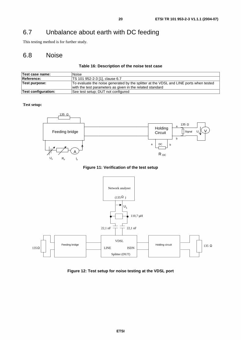
Table 16: Description of the noise test case
Test case name: Noise Reference: TS 101 952-2-3 [1], clause 6.7 Test purpose: To evaluate the noise generated by the splitter at the VDSL and LINE ports when tested
with the test parameters as given in the related standard Test configuration: See test setup; DUT not configured
Test setup:
UF RF
Feeding bridge
A R DC
Signal VU1
a b
135 Ω
HoldingCircuit
a
b
DC
135 Ω
IF
Figure 11: Verification of the test setup
135Ω135 Ω
ISDN
VDSL
LINE
110,7 µH
22,1 nF
Feeding bridge Holding circuit
Network analyser
)
Splitter (DUT)
U1
22,1 nF
(135 Ω
Figure 12: Test setup for noise testing at the VDSL port

ETSI
ETSI TR 101 953-2-3 V1.1.1 (2004-07) 21
(135 Ω)
Network analyser
135 ΩFeedingbrisge
Holdingcircuit
110,7 µH
ISDN
VDSL
LINE
Splitter (DUT)
135 Ω
U1
22,1 nF 22,1 nF
Figure 13: Test setup for noise testing at the LINE port
The Feeding Bridge and Holding Circuit must comply with the requirements as specified in TBR 038 [4]. Furthermore the insertion loss of Feeding and Holding Circuit in the "signal" path shall be less than 1 dB in the frequency range from 138 kHz to 12 MHz.
Test Parameters:
Table 17: Test parameters for the noise test case
Parameter Value Frequency range 138 kHz to 12 MHz Termination at VDSL: ZT-VDSL ZT-VDSL = ZVDSL-I
Level of feeding voltage 50 VDC
Load resistance RDC 470 Ω DC feeding current IF 0 mA
20 mA 40 mA 60 mA
Polarity of feeding voltage normal and reversed, alternating between the single measurements Ports to be tested LINE
VDSL Optional tests none
Test matrix:
Table 18: Test matrix for the noise test case
TS 101 952-2-3 [1] Essential tests Frequency range 138 kHz to 12 MHz X X DC feeding voltage/current +50 VDC/0 mA X X -50 VDC/20 mA X X
+50 VDC/40 mA X X -50 VDC/60 mA X X
ZT-VDSL = ZVDSL-I X X
Measured at port LINE X X Measured at port ISDN X X Number of tests 8 tests 8 tests

ETSI
ETSI TR 101 953-2-3 V1.1.1 (2004-07) 22
Test procedure notes:
Before starting the measurements the test setup shall be verified with respect to the noise present when having the DC source as well as the holding circuit present in the setup but not having connected the splitter under test. Measuring U1 as shown in the test setup is an appropriate way to do so. The observed value for U1 (dBm/Hz) measured with a bandwidth of 10 kHz should be at least 10 dB lower than the value that is to be proven.
Values of DC feeding current IF are set by adjusting the values of the external circuitry (namely UF, RF and RDC).
Test results:
Test result shall be recorded as follows:
• U1 in dBm/Hz, where U1 is the voltage observed, when the splitter is connected as in test setup.
Measuring notes:
The inaccuracy of the measurement which results from tolerances in the test setup and its containing equipment shall be carefully considered. When giving a verdict on the test results with respect to the requirement in the related standard this tolerance in the test results need to be taken into account.
It is considered that this test is primarily concerned with noise generated by an active splitter. Passive splitters are not considered likely to be a source of spectral noise.
6.9 DC requirements
6.9.1 DC resistance to earth
Table 19: Description of the DC resistance to earth test case
Test case name: DC resistance to earth Reference: TS 101 952-2-3 [1], clause 6.1.1 Test purpose: To measure the DC resistance between each terminal (i.e. A-wire and B-wire) of the
splitter and earth. This test only applies to splitters which provide a terminal which is connected to ground. (See note.)
Test configuration: See test setup; DUT not configured NOTE: A splitter is considered to provide an earth connection, as soon as there is a specific terminal which might lead
to the reasonable assumption that is could be connected to ground. Furthermore, this test is to be performed, when there are non-insulated conducting parts at the enclosure.

ETSI
ETSI TR 101 953-2-3 V1.1.1 (2004-07) 23
Test setup:
a
b
RF
Splitter(DUT)S
UF
A
V
Earth
UT
U
I
LINE
A
ISDN
ADSL
RDC
Figure 14: Test setup for DC resistance to earth (LINE port)
Test parameters:
Table 20: Test parameters for the DC Resistance to earth test case
Parameter Value Level of the DC test voltage UT +120 VDC
-120 VDC
Level of feeding voltage 50 VDC Level of feeding current 0 mA to 60 mA Polarity of feeding voltage normal and reversed, alternating between the single measurements Position of Switch S a-wire
b-wire Termination at ISDN port RDC = 470 Ω Termination at VDSL port open circuit Ports to be tested LINE
ISDN VDSL

ETSI
ETSI TR 101 953-2-3 V1.1.1 (2004-07) 24
Test Matrix:
Table 21: Test matrix for the DC resistance to earth test case
TS 101 952-2-3 [1] Essential tests DC source voltage +120 VDC
DC source voltage -120 VDC
X X
X X
UT applied to LINE
UT applied to ISDN (only with DC path
break) UT applied to VDSL
X X
X
X X
X
Switch in position a Switch in position b
X X
X X
DC feeding voltage/current +50 VDC/0 mA
-50 VDC/60mA
X X
X X
Termination at ISDN RDC = 470 Ω
Termination at ISDN open circuit
X X
Number of tests 16 tests (24 for splitters
breaking the DC path)
16 tests (24 for splitters
breaking the DC path)
Test procedure notes:
NOTE 1: When a DC current is flowing, the difference in the test results between the measurements from a-wire to earth and b-wire to earth is expected to be negligible (only the RDC and the series resistance of the holding circuit is added to the result). With this, at the LINE port and the ISDN port testing only one wire against earth is sufficient when there is no break in the DC path.
NOTE 2: Splitters breaking the DC path should be tested completely (all three ports), splitters not breaking the DC path can use a reduced test which only requires testing at the VDSL port and the LINE port.
NOTE 3: At the VDSL port a- and b- wire should be tested separately, however, a DC current need not be applied.
NOTE 4: Verification of the test result: To verify the test result, a well-known resistor of about 5 MΩ (measured independently at an uncertainty of less than 0,1 %) should be connected to the test setup and the resulting current should be compared with the theoretically expected result.
Test results:
Test result shall be recorded as follows:
• I in µA, where: I is the value of the observed current, which is flowing into the branch under test.
• RDC-wire-earth, where RDC-wire-earth = UT/I.
Measuring notes:
The inaccuracy of the measurement that results from tolerances in the test setup and its containing equipment shall be carefully considered. When giving a verdict on the test results with respect to the requirement in the related standard this tolerance in the test results need to be taken into account.
6.9.2 Isolation resistance between A-wire and B-wire
Table 22: Description of the isolation resistance between A-wire and B-wire test case
Test case name: Isolation resistance between A-wire and B-wire Reference: TS 101 952-2-3 [1], clause 6.1.2 Test purpose: To measure the isolation resistance between the A-wire and B-wire Test configuration: See test setup; DUT not configured

ETSI
ETSI TR 101 953-2-3 V1.1.1 (2004-07) 25
Test setup:
a
b
ISDN
VDSLLINE
Earth
U
Rt
UTUF
A
V
I
Splitter(DUT)
Figure 15: Test setup for isolation resistance between A-wire and B-wire (LINE port)
Test parameters:
Table 23: Test parameters for the isolation resistance between A-wire and B-wire test case
Parameter Value Level of the test voltage UT +120 VDC
-120 VDC
Termination at ports under test open circuit Termination at ports not under test open circuit Ports to be tested LINE
ISDN VDSL
Test matrix:
Table 24: Test matrix for the isolation resistance between A-wire and B-wire test case
TS 101 952-2-3 Essential tests DC source voltage +120 VDC X X DC source voltage -120 VDC X X
VDC applied to LINE X X VDC applied to ISDN X X
VDC applied to VDSL X X
Number of tests 6 tests 6 tests
Test procedure notes:
NOTE 1: If the splitter is not breaking the DC path, it is sufficient to measure at one port (the LINE port). If the splitter is breaking the DC path, both ports (LINE and ISDN) should be measured.
NOTE 2: Verification of the test result: To verify the test result, a well-known resistor of about 5 MΩ (measured independently at an uncertainty of less than 0,1 %) should be connected to the test setup and the resulting current should be compared with the theoretically expected result.
NOTE 3: It is not expected that a DC level occurs in normal operation at the VDSL port and therefore it may be appropriate to delete the requirement for DC resistance between open wires at the VDSL port.

ETSI
ETSI TR 101 953-2-3 V1.1.1 (2004-07) 26
Test results:
Test result should be recorded as follows:
• I in µA, where: I is the value of the observed current, which is flowing into the branch under test.
• RDC-A-wire-B-wire, where RDC-A-wire-B-wire = UT/I.
Measuring notes:
The inaccuracy of the measurement that results from tolerances in the test setup and its containing equipment shall be carefully considered. When giving a verdict on the test results with respect to the requirement in the related standard this tolerance in the test results need to be taken into account.
6.9.3 DC series resistance
Table 25: Description of the DC series resistance test case
Test case name: DC series resistance Reference: TS 101 952-2-3 [1], clause 6.1.3 Test purpose: To measure the DC series resistance of the splitter Test configuration: See test setup; DUT not configured
Test setup:
Splitter(DUT)
RDC
LINE
ISDN
ADSL
V
V
U2
U1
a
b
a b
UF RF
A
IF
IF
Figure 16: Test setup for series resistance between A-wire and B-wire (LINE to ISDN)
Test parameters:
Table 26: Test parameters for the DC series resistance test case
Parameter Value Level of feeding voltage UF 50 VDC
Value of feeding current IF 0 mA to 60 mA
Polarity of feeding voltage normal and reversed, alternating between the single measurements
Termination at VDSL port Open circuit Termination at port not under test (RDC = 0 Ω) Short circuit
Ports to be tested LINE ISDN
ETSI
ETSI TR 101 953-2-3 V1.1.1 (2004-07) 27
Test matrix:
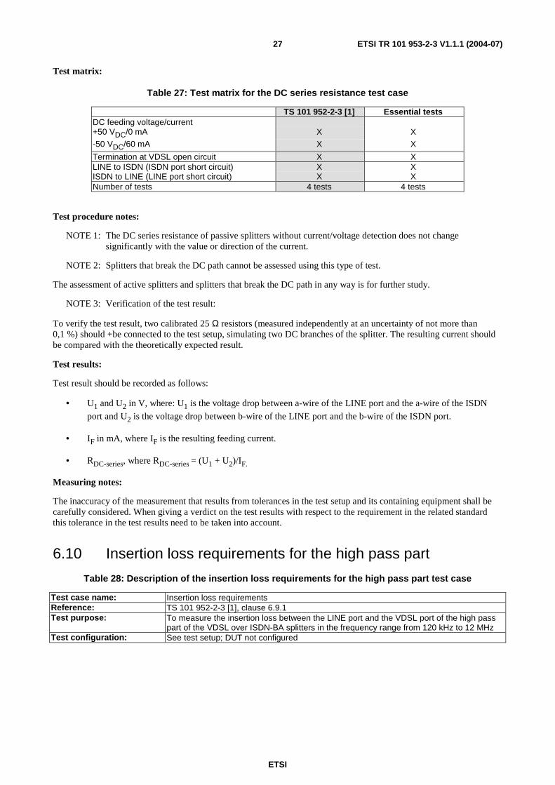
Table 27: Test matrix for the DC series resistance test case
TS 101 952-2-3 [1] Essential tests DC feeding voltage/current +50 VDC/0 mA X X -50 VDC/60 mA X X
Termination at VDSL open circuit X X LINE to ISDN (ISDN port short circuit) ISDN to LINE (LINE port short circuit)
X X
X X
Number of tests 4 tests 4 tests
Test procedure notes:
NOTE 1: The DC series resistance of passive splitters without current/voltage detection does not change significantly with the value or direction of the current.
NOTE 2: Splitters that break the DC path cannot be assessed using this type of test.
The assessment of active splitters and splitters that break the DC path in any way is for further study.
NOTE 3: Verification of the test result:
To verify the test result, two calibrated 25 Ω resistors (measured independently at an uncertainty of not more than 0,1 %) should +be connected to the test setup, simulating two DC branches of the splitter. The resulting current should be compared with the theoretically expected result.
Test results:
Test result should be recorded as follows:
• U1 and U2 in V, where: U1 is the voltage drop between a-wire of the LINE port and the a-wire of the ISDN
port and U2 is the voltage drop between b-wire of the LINE port and the b-wire of the ISDN port.
• IF in mA, where IF is the resulting feeding current.
• RDC-series, where RDC-series = (U1 + U2)/IF.
Measuring notes:
The inaccuracy of the measurement that results from tolerances in the test setup and its containing equipment shall be carefully considered. When giving a verdict on the test results with respect to the requirement in the related standard this tolerance in the test results need to be taken into account.
6.10 Insertion loss requirements for the high pass part
Table 28: Description of the insertion loss requirements for the high pass part test case
Test case name: Insertion loss requirements Reference: TS 101 952-2-3 [1], clause 6.9.1 Test purpose: To measure the insertion loss between the LINE port and the VDSL port of the high pass
part of the VDSL over ISDN-BA splitters in the frequency range from 120 kHz to 12 MHz Test configuration: See test setup; DUT not configured

ETSI
ETSI TR 101 953-2-3 V1.1.1 (2004-07) 28
Test setup:
22,1 nF
ISDN
port
LINE
port Holdingcircuit
RDC
Feedingbridge
A
RF
IF
UF
ZSource
Us
Signalsource 22,1 nF
U1
Levelmeter
V
135 Ω
110,7 µH
VDSLport
ISDN
port
LINE
port Holdingcircuit
RDC
ZT
Feedingbridge
A
RF
IF
ZSource
Us
Signalsource
22,1 nF 22,1 nF
U2
Levelmeter
V
135 Ω
110,7 µH
VDSLport
Splitter(DUT)
with blockingcapacitors 2 x 27 nF
ZVDSL-I
UF
ZVDSL-I
Figure 17: Test setup for insertion loss testing on a splitter from LINE to VDSL port
Feeding Bridge and Holding Circuit must comply with the requirements as specified in TBR 038 [4]. As the TBR 038 [4] defines the feeding bridge and the holding circuit only for the voice frequency band, special care need to be taken on the electrical characteristics of the feeding bridge and the holding circuit in the ISDN-BA and VDSL specific frequency band.
ETSI
ETSI TR 101 953-2-3 V1.1.1 (2004-07) 29
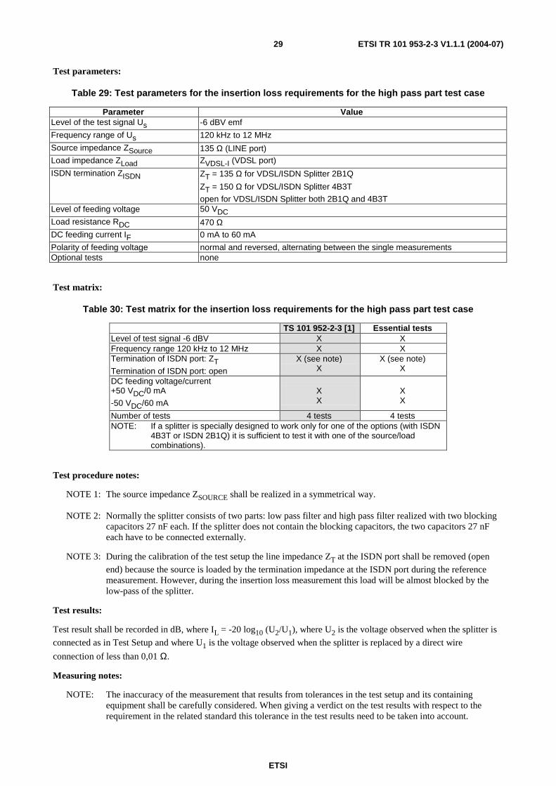
Test parameters:
Table 29: Test parameters for the insertion loss requirements for the high pass part test case
Parameter Value Level of the test signal Us -6 dBV emf
Frequency range of Us 120 kHz to 12 MHz
Source impedance ZSource 135 Ω (LINE port) Load impedance ZLoad ZVDSL-I (VDSL port)
ISDN termination ZISDN ZT = 135 Ω for VDSL/ISDN Splitter 2B1Q
ZT = 150 Ω for VDSL/ISDN Splitter 4B3T
open for VDSL/ISDN Splitter both 2B1Q and 4B3T Level of feeding voltage 50 VDC
Load resistance RDC 470 Ω DC feeding current IF 0 mA to 60 mA
Polarity of feeding voltage normal and reversed, alternating between the single measurements Optional tests none
Test matrix:
Table 30: Test matrix for the insertion loss requirements for the high pass part test case
TS 101 952-2-3 [1] Essential tests Level of test signal -6 dBV X X Frequency range 120 kHz to 12 MHz X X Termination of ISDN port: ZT
Termination of ISDN port: open
X (see note) X
X (see note) X
DC feeding voltage/current +50 VDC/0 mA
-50 VDC/60 mA
X X
X X
Number of tests 4 tests 4 tests NOTE: If a splitter is specially designed to work only for one of the options (with ISDN
4B3T or ISDN 2B1Q) it is sufficient to test it with one of the source/load combinations).
Test procedure notes:
NOTE 1: The source impedance ZSOURCE shall be realized in a symmetrical way.
NOTE 2: Normally the splitter consists of two parts: low pass filter and high pass filter realized with two blocking capacitors 27 nF each. If the splitter does not contain the blocking capacitors, the two capacitors 27 nF each have to be connected externally.
NOTE 3: During the calibration of the test setup the line impedance ZT at the ISDN port shall be removed (open
end) because the source is loaded by the termination impedance at the ISDN port during the reference measurement. However, during the insertion loss measurement this load will be almost blocked by the low-pass of the splitter.
Test results:
Test result shall be recorded in dB, where IL = -20 log10 (U2/U1), where U2 is the voltage observed when the splitter is
connected as in Test Setup and where U1 is the voltage observed when the splitter is replaced by a direct wire
connection of less than 0,01 Ω.
Measuring notes:
NOTE: The inaccuracy of the measurement that results from tolerances in the test setup and its containing equipment shall be carefully considered. When giving a verdict on the test results with respect to the requirement in the related standard this tolerance in the test results need to be taken into account.

ETSI
ETSI TR 101 953-2-3 V1.1.1 (2004-07) 30
History
Document history
V1.1.1 July 2004 Publication