tr-547 tapi v2.1.3 reference implementation agreement
TRANSCRIPT

TR-547 TAPI v2.1.3 Reference Implementation Agreement
TAPI v2.1.3 Reference Implementation Agreement TR-547
Version 1.0 June 2020
ONF Document Type: Technical Recommendation
DisclaimerTHIS SPECIFICATION IS PROVIDED "AS IS" WITH NO WARRANTIES WHATSOEVER, INCLUDING ANY WARRANTY OF MERCHANTABILITY, NONINFRINGEMENT, FITNESS FOR ANY PARTICULAR PURPOSE, OR ANY WARRANTY OTHERWISE ARISING OUT OF ANY PROPOSAL, SPECIFICATION OR SAMPLE.
Any marks and brands contained herein are the property of their respective owners. Open Networking Foundation 1000 El Camino Real, Suite 100, Menlo Park, CA 94025 www.opennetworking.org
©2018 Open Networking Foundation. All rights reserved.Open Networking Foundation, the ONF symbol, and OpenFlow are registered trademarks of the Open Networking Foundation, in the United States and/or in other countries. All other brands, products, or service names are or may be trademarks or service marks of, and are used to identify, products or
services of their respective owners.
Table of Contents Disclaimer
Document History 1 Introduction
1.1 General introduction to the model 1.2 Introduction to this document
2 RESTCONF/YANG Protocol considerations 2.1 Root tree discovery 2.2 YANG model's discovery 2.3 Operation API (RPC) vs Data API (REST) 2.4 Query filtering 2.5 Data encoding
2.5.1 Namespaces 2.6 Notifications
2.6.1 SSE vs WebSocket 3 ONF Transport – API (TAPI) considerations
3.1 TAPI SDK version and documentation 3.2 TAPI Information model
3.2.1 Context 3.2.2 Node and Topology Aspects of Forwarding Domain
3.2.2.1 Topology 3.2.2.2 Node 3.2.2.3 Link
3.2.3 Node Edge Point v/s Service End Point v/s Connection End Point3.2.3.1 Node-Edge-Point (NEP) 3.2.3.2 Service-Interface-Point (SIP) 3.2.3.3 Connection-End-Point (CEP)
3.2.4 Service, Connection and Route3.2.4.1 Connectivity-Service (CS) 3.2.4.2 Connection 3.2.4.3 Route 3.2.4.4 Path
3.3 TAPI Data API

3.4 TAPI Notifications 4 Topology abstraction model
4.1 Model guidelines 4.2 Inventory considerations 4.3 Network scenarios
4.3.1 Scenario 1: ROADM network equipped with OTN matrices4.3.1.1 Model representation (Transitional Link approach)
4.3.2 Scenario 2: Point-to-point DWDM link + Mesh DWDM network4.3.2.1 Model representation
5 Connectivity service model 5.1 Model guidelines
5.1.1 Multi-layer connectivity service provisioning and connection generation 5.1.2 Resiliency mechanism at connectivity service 5.1.3 Topology and service constrains for connectivity services
6 Use cases Low Level designs (LLDs) 6.1 Topology and services discovery
6.1.1 Use Case 0a: Context & Service Interface Points discovery (pooling mode)6.1.1.1 Required parameters
6.1.2 Use Case 0b: Topology discovery (synchronous mode)6.1.2.1 Required parameters 6.1.2.2 Expected results
6.1.3 Use case 0c: Connectivity Service discovery (synchronous mode)6.1.3.1 Required parameters
6.2 Unconstrained E2E Service Provisioning 6.2.1 Use case 1a: Unconstrained DSR Service Provisioning single wavelength (<100G).
6.2.1.1 Required parameters 6.2.1.2 Expected results
6.2.2 Use Case 1b: Unconstrained DSR Service Provisioning multi wavelength (beyond 100G).6.2.2.1 Expected results
6.2.3 Use case 1c: Unconstrained ODU Service Provisioning 6.2.4 Use case 1d: Unconstrained PHOTONIC_MEDIA/OTSi Service Provisioning
6.2.4.1 Expected results 6.2.5 Use case 1e: Unconstrained PHOTONIC_MEDIA/OTSiA Service Provisioning
6.2.5.1 Expected results 6.2.6 Use case 1f: Unconstrained PHOTONIC_LAYER_QUALIFER_MC Service Provisioning
6.2.6.1 Expected results 6.3 Constrained Provisioning
6.3.1 Use case 3a: Include/exclude a node or group of nodes.6.3.1.1 Required parameters
6.3.2 Use case 3b: Include/exclude a link or group of links.6.3.2.1 Required parameters
6.3.3 Use case 3c: Include/exclude the route used by other service.6.3.3.1 Required parameters
6.4 Inventory 6.4.1 Use case 4a: Introduction of references to external inventory model. 6.4.2 Use case 4b: Complete Inventory model for NBI Interface.
6.4.2.1 Required parameters 6.4.2.2 Relative location of component with TAPI 2.1.3 using holder location
6.5 Resiliency 6.5.1 Use case 5a: 1+1 OLP OMS/OTS Protection with Diverse Service Provisioning
6.5.1.1 Expected result 6.5.2 Use case 5b: 1+1 OLP Line Protection with Diverse Service Provisioning
6.5.2.1 Expected results 6.5.2.2 Required parameters
6.5.3 Use case 5c: 1+1 protection with Diverse Service Provisioning (eSNCP)6.5.3.1 Expected result 6.5.3.2 Required parameters
6.5.4 Use case 6a: Dynamic restoration policy for unconstrained and constrained connectivity services.6.5.4.1 Required parameters
6.5.5 Use case 6b: Pre-Computed restoration policy for unconstrained and constrained connectivity services.6.5.5.1 Required parameters
6.5.6 Use case 7a: Dynamic restoration and 1+1 protection of DSR/ODU unconstrained service provisioning.6.5.6.1 Required parameters
6.5.7 Use case 7b: Pre-Computed restoration policy and 1+1 protection of DSR/ODU unconstrained service provisioning.6.5.7.1 Required parameters
6.5.8 Use case 8: Permanent protection 1+1 for use cases6.5.8.1 Required parameters
6.6 Maintenance 6.6.1 Use Case 10: Service deletion (applicable to all previous use cases)
6.7 Planning 6.7.1 Use case 12a: Pre-calculation of the optimum path (applicable to all previous use cases)
6.7.1.1 Required parameters 6.7.2 Use case 12b: Simultaneous pre-calculation of two disjoint paths
6.8 Notifications and alarms. 6.8.1 Use case 13a: Subscription to notification service. 6.8.2 Use case 14a: Notification of new topology element (topology, link, node, node-edge-point) inserted/removed in/from the network 6.8.3 Use case 14b: Notification of new connectivity-service element inserted/removed in/from the network. 6.8.4 Use case 14c: Notification of new path-computation element inserted/removed in/from the network 6.8.5 Use case 15a: Notification of status change on existing topology element (topology, link, node, node-edge-point) in the network.

6.8.6 Use case 15b: Notification of status change on existing connectivity-service element in the network. 6.8.7 Use case 15c: Notification of status change on the switching conditions of an existing connection element in the network.
7 References 8 Definitions
8.1 Terms defined elsewhere 8.2 Terms defined in this TR 8.3 Abbreviations and acronyms
9 Individuals engaged 9.1 Editors 9.2 Contributors
List of Figures Figure 2-1 Example SDN architecture for WDM/OTN network
Figure 3-1 Transport API Functional Architecture Figure 3-2 TAPI Mapping from ITU-T.
Figure 4-1 Media-channel entities relationship. Figure 4-2 NS-1: OTN/WDM Network scenario
Figure 4-3 NS-1. T0: TAPI Topology Flat Abstraction model, transitional link approach. Figure 4-4 NS-1. T0: TAPI Topology Flat Abstraction model, transitional link approach (Device view).
Figure 4-5 NS-1.T0: TAPI Topology Flat Abstraction model multi-layer node approach. Figure 4-6 NS-1.T0: TAPI Topology Flat Abstraction model multi-layer node approach (Device view).
Figure 4-7 NS-2: OTN/WDM Network scenario 2. Figure 4-8 NS-2. T0: TAPI Topology Flat Abstraction Transitional Link model.
Figure 4-9 NS-2. T0: TAPI Topology Flat Abstraction Transitional Link model (Device view). Figure 4-10 NS-2. T0: TAPI Topology Flat Abstraction Multi-Layer Node model.
Figure 4-11 NS-2. T0: TAPI Topology Flat Abstraction Multi-Layer Node model (Device view). Figure 6-1 UC-0a: Context and Service Interface Point - LLD Workflow.
Figure 6-2 UC-0b: Topology discovery - LLD Workflow. Figure 6-3 TAPI topology representation at "day 0" following Transitional Link modelling approach. Figure 6-4 TAPI topology representation at "day 0" following Multi-layer Node modelling approach.
Figure 6-5 UC-0c: Connectivity Service - LLD Workflow. Figure 6-6 UC-1: Unconstrained end-to-end service provisioning.
Figure 6-7 TAPI Logical Termination Point Template – Basic Arrangements. Figure 6-8 UNI Modelling simplifications
Figure 6-9 Connectivity Service 10GE client signal over ODU2 (DSR-ODU Fixed Mapping) over ODU4 over single OTSi – Transitional Link modelling Figure 6-10 Connectivity Service 10GE client signal over ODU2 (DSR-ODU Fixed Mapping) over ODU4 over single OTSi – Multi-layer node modelling.
Figure 6-11 Connectivity Service 1GE client signal over ODU0 over ODU2 over ODU4 (Fixed DSR-ODU mapping, flexible ODU allocation)Figure 6-12 Connectivity Service 1GE client signal over ODU0 over ODU2 over ODU4 (Fixed DSR-ODU mapping, flexible ODU allocation) with
intermediate ODU0 switchingFigure 6-13 Connectivity Service 10GE client signal over ODU2 over ODU4 (Fixed DSR-ODU mapping, flexible ODU allocation) with intermediate
transponder regeneration. Figure 6-14 200GE over ODUc2 connectivity-service over two OTSi/OTSiMC over a single physical (PHOTONIC-MEDIA_OMS) port (Transitional Link). Figure 6-15 200GE over ODUc2 connectivity-service over two OTSi/OTSiMC over a single physical (PHOTONIC-MEDIA_OMS) port (Multi-Layer Node).
Figure 6-16 OTSi single lambda connectivity-service - Transitional link model. Figure 6-17 OTSi single lambda connectivity-service - Multi-layer node approach.
Figure 6-18 OTSiA multi-wavelength connectivity-service (transitional link model abstraction). Figure 6-19 OTSiA multi-wavelength connectivity-service (multi-layer node model abstraction).
Figure 6-20 Media-channel entities relationship. Figure 6-21 Full Bidirectional - UNI and OMS bidirectional scenario.
Figure 6-22 Mixed Scenario - UNI bidirectional and OMS unidirectional. Figure 6-23 Full Unidirectional - UNI and OMS unidirectional scenario.
Figure 6-24 UC-4b Hierarchical arrangement of equipment objects with TAPI 2.1.3. Figure 6-25 UC-4b Network Element Subracks container-holder location examples.
Figure 6-26 UC-5c OMS OLP protection schemas. Figure 6-27 UC-5a OLP protection TAPI representation.
Figure 6-28 UC-5b Line OLP protection schema. Figure 6-29 UC-5b: Resiliency workflow.
Figure 6-30 UC-5b OLP TAPI Connectivity-Service low-level description. Figure 6-31 UC-5b OLP TAPI Connectivity-Service low-level description. Unidirectional OLS modelling.
Figure 6-32 UC-5c eSNCP protection schema. Figure 6-33 UC5c: eSNCP protection schema for HO-ODUk Top Connection.
Figure 6-34 UC-6a: Resiliency workflow. Figure 6-35 UC-10: Service Deletion workflow.
Figure 6-36 UC-12a: Pre-calculation of the optimum path workflow. Figure 6-37 UC-12b: Simultaneous pre-calculation of two disjoint paths
Figure 6-38 UC-13a: Subscription to notification stream service

List of Tables Table 1: RESTCONF Query filters
Table 2: TAPI YANG models summary. Table 3: Minimum subset required of TAPI RESTCONF Data API
Table 4: Inventory-id fields format. Table 5: Inventory-id fields combination allowance.
Table 7: Context object definition Table 8: Service Interface Point (SIP) object definition
Table 9: Topology object definition Table 10: Node object definition
Table 11: Node-edge-point object definition Table 12: Node-rule-group object definition
Table 13: Rule object definition Table 14: Link object definition
Table 15: Connectivity-service object definition Table 16: Connectivity-service-end-point object definition
Table 17: Connection object definition Table 18: Connection-end-point object definition
Table 19: ODU-Connection-end-point-spec object definition Table 20: otsi-connection-end-point-spec object definition
Table 21: OTSI-Assembly-connection-end-point-spec object definition Table 22 media-channel-connection-end-point-spec object definition
Table 23 ots-media-channel-connection-end-point-spec object definition Table 23: Route object definition
Table 24: otsia-connectivity-service-end-point-spec object definition Table 25: mca-connectivity-service-end-point-spec object definition
Table 26: Connectivity-service node topology-constrains object definitions. Table 27: Connectivity-service link topology-constrains object definitions.
Table 28: Connectivity-service diversity-exclusion and coroute-inclusion object definitions. Table 29: Main parameters for equipment model required. Table 30: Equipment object's attributes required for UC4b.
Table 31: Common-holder-properties object's attributes required for UC4b. Table 32: Common-equipment-properties object's attributes required for UC4b.
Table 33: Common-actual-properties object's attributes required for UC4b. Table 34: Device object attributes required for UC4b.
Table 35: Connectivity-service attributes for 1+1 UC5b. Table 36: Connectivity-service-End-Points attributes for UC5b.
Table 37: Connection attributes for UC5b. Table 38: Switch-control attributes for UC5b.
Table 39: Switch attributes for UC5b. Table 40: Connectivity-service attributes for UC5c. Table 41: Connectivity-service attributes for UC6a. Table 42: Connectivity-service attributes for UC6a. Table 43: Connectivity-service attributes for UC7a. Table 44: Connectivity-service attributes for UC7b.
Table 45: Connectivity-service attributes for UC8. Table 46: Path-computation-context attributes.
Table 47: Path-comp-serv object's attributes. Table 48: Path-service endpoint object's attributes.
Table 49: Topology constraint object's attributes. Table 50: Routing constraint object's attributes. Table 51: Objective function object's attributes.
Table 52: Optimization-constraint object's attributes.
Document History
Version Date Description of Change
0.1 August 06, 2019
Initial version of the Reference Implementation document of TAPI v2.1.2
0.2 December 03,2019
General upgrade with new use cases.
0.5 February 18, 2020
First general TAPI group review.
0.7 April 08, 2020 Model consolidation into v2.1.3. General review of connectivity model, photonic media and resiliency concepts applicable to proposed use cases.
0.8 April 15, 2020 Refinement of the UC4b
0.9 April 21, 2020 Full review until section 4.3
0.10 May 26, 2020 Full review, with pending comments for tracking discussion into following versions.

0.11 May 26, 2020 Fully reviewed document with latest contributions into Transitional Link modelling, UNI interfaces simplification description and protection scheme refinements into UCs 5a, 5b and 5c.
1.0 June 23, 2020 TR Official version.
Introduction
General introduction to the model
This ONF Technical Recommendation (TR) focuses on the definition of a Reference Implementation guide for a TRANSPORT-API (TAPI) based RESTCONF implementation focus on the v2.1.3 version of the TAPI information models (pruned/refactored from the ONF Core Information Model 1.4) and available in the public ONF GitHub repository at:https://github.com/OpenNetworkingFoundation/TAPI/releases/tag/v2.1.3
Introduction to this document
The purpose of this document is to describe a set of guidelines and recommendations for a standard use of the TAPI models in combination with RESTCONF protocol for the implementation of the interface between network systems in charge of the control/management of networks based on WDM
/OTN technologies.The target architectures, for which this reference interface is proposed, it is conceptually described in Figure 2-1. As depicted in the architecture, this reference NBI will be the single interface between Operations Support System (OSS), Orchestrator, (super) Controller, etc Any system with a repository
. The scope of the architecture covers multiple domains within that maintains alignment with a view of the underlying system as presented by the controller.the same network, and it might consist of one or more layers of controllers, where each layer controller will export a certain level of abstraction through its TAPI context (e.g., a hierarchical controller may consume several domain SDN-C TAPI contexts to conform a multi-domain network and exposed it as an aggregated TAPI context). In this document we will refer the lower layer of controllers as SDN domain controller or SDN-C, and, to any hierarchical controller performing the same management/control capabilities or use cases over multiple network domains as Software-Defined Transport Network (SDTN) controller.Thus, this specification is intended for the interface between an SDN-C and Orchestrator, (super) Controller or client layer systems (such OSS) where the SDN-C provides its network management through a TAPI context and maintains a synchronized view in a database.Moreover, the client layer which will consume the TAPI context systems may have distinct roles (e.g., physical inventory) and that they may be composed of different components or applications. E.g., an OSS system composed by different pieces dedicated to different applications (such inventory, assurance or planning).This document aims to define the base requirements for any TAPI Server entity (e.g., a SDN-C) which is intended to expose the management/control
At the time management is automated it simply becomes control as explained by [ONF Core Model].
capabilities of any use case such activation/configuration, service provisioning, path-computation and monitoring over a WDM/OTN network, through the interface defined in this document.The term management/control shall express that the scope is much wider than just configuring. The proposed common interface shall account for:
Configuration, e.g. for automating and optimizing the network services creation and processes.Status, e.g. for automated configuration depending on current network status.Events (Alarms), e.g. for automated initiation of countermeasures.Current and Historical Performance Values, e.g. for perpetual network analysis.
This specification is supported by standards, protocol specifications, IETF RFCs, ITU-T recommendations and the ONF Transport API (TAPI) documentation. The appropriate references to this supplementary material are included where appropriate along the document to support the statements which conforms this specification. However, this document does not intend to re-define the protocols or information models composing the specification but to complement, clarify or extends in those cases where a corner case or different interpretations have been found along the mentioned standards.
Figure 2-1 Example SDN architecture for WDM/OTN network
RESTCONF/YANG Protocol considerations

RESTCONF [RFC 8040] is proposed as the transport protocol for all the defined management operations in the SDN architecture NBIs.RESTCONF is a HTTP-based protocol that provides a programmatic interface for accessing data defined in YANG 1.0 [RFC 6020] using the data store concepts defined in the Network Configuration Protocol (NETCONF) [RFC 6241].The RESTCONF specification consists of the following resources:
{+restconf}/data (Data API): Create/Retrieve/Update/Delete (CRUD) based API for the entire data tree defined in the TAPI information model YANG files (see section 4).{+restconf}/operations (Operations API): RPC based API consisting on a small set of operations defined as RPCs in the TAPI information model YANG files.{+restconf}/data/ietf-restconf-monitoring:restconf-state/streams (Notifications API): Notifications implementation of RESTCONF protocol is defined in .https://tools.ietf.org/html/rfc8040#section-6.3{+restconf}/yang-library-version: This mandatory leaf identifies the revision date of the "ietf-yang-library" YANG module that is implemented by this server.{+restconf}/data/ietf-restconf-monitoring:restconf-state/capabilities: leaf to report the server capability of supporting query parameters defined in .https://tools.ietf.org/html/rfc8040#section-9.1
Root tree discovery
The RESTCONF API root resource can be discovered by getting the resource ([RFC 6415]) and using the <Link> {+restconf} "/.well-known/host-meta"element containing the attribute."restconf"The client will send the following query:GET /.well-known/host-meta HTTP/1.1Host: example.comAccept: application/xrd+xml The server might respond as follows:HTTP/1.1 200 OKContent-Type: application/xrd+xmlContent-Length: nnn <XRD xmlns='http://docs.oasis-open.org/ns/xri/xrd-1.0'><Link rel='restconf' href='/restconf'/></XRD>
YANG model's discovery
<ac:structured-macro ac:name="anchor" ac:schema-version="1" ac:macro-id="36e9105f-a721-44ac-b570-ec747826d3d0"><ac:parameter ac:name="">_Ref1737226</ac:parameter></ac:structured-macro><ac:structured-macro ac:name="anchor" ac:schema-version="1" ac:macro-id="389fc887-369a-4036-9e5f-4e693d897428"><ac:parameter ac:name="">_Toc14454012</ac:parameter></ac:structured-macro>RESTCONF utilizes the YANG library [RFC 7895] and [RFC 8525] to allow a client to discover the YANG module conformance information for the server, in case the client wants to use it.The mandatory resource is used to clearly identify the version of the YANG library used by the server.{+restconf}/yang-library-versionThe server MUST implement the " " module, which MUST identify all the YANG modules used by the server, within the "modules-stateietf-yang-library/module" and "yang-library/module-set/module" list resource. The modules set resource is located at (both implementations are accepted so far):
According to [RFC 7895]: {+restconf}/data/ietf-yang-library:modules-stateAccording to [RFC 8525]: {+restconf}/data/ietf-yang-library:yang-library
Operation API (RPC) vs Data API (REST)
Currently there are two allowed APIs resources defined in RESTCONF. Although both are compatible and valid, given the low penetration in the industry of the RPC-based API implementation, it is not currently included in this specification.Thus, the current specification takes the support of the RESTCONF 'data' API as mandatory; while the 'operations' API, based on the TAPI defined RPCs, is considered optional.
Query filtering
According to RESTCONF specification, each operation allows zero or more query parameters to be present in the request URI. Specifically, query operations' parameters are described in . Thus, the following query parameters MUST be supported by any interface compliant Section 4.8 of [RFC 8040]with this specification:
Table 1: RESTCONF Query filters
Name Methods Description
content GET, HEAD
Select config and/or non-config data resources
depth GET, HEAD
Request limited subtree depth in the reply content
fields GET, HEAD
Request a subset of the target resource contents
filter GET, HEAD
Boolean notification filter for event stream resources

start-time GET, HEAD
Replay buffer start time for event stream resources
stop-time GET, HEAD
Replay buffer stop time for event stream resources
The specific use of these query parameters will be detailed in the different Use Cases Low Level Design (LLDs) included in section 7.The query parameter URIs SHALL be listed in the leaf-list as part of the container definition "depth", "fields", "filter", "replay" and "with-defaults" "capability"in the module, defined in , to advertise the server capability of supporting these query parameters. This "ietf-restconf-monitoring" Section 9.3 of [RFC 8040]resource shall be located at:
{+restconf}/data/ietf-restconf-monitoring:restconf-state/capabilties
Data encoding
JSON encoding formats MUST be supported according to with .Section 3.2 of [RFC 8040]The solution adhering to this specification MUST support media type "application/yang-data+json" as defined in . This MUST be advertised in [RFC 7951]the HTTP Header fields "Accept" or "Content-Type" of the corresponding HTTP Request/Response messages.
Namespaces
According to , "Section 1.1.5 of [RFC 8040] The JSON representation is defined in "JSON Encoding of Data Modeled with YANG" [RFC7951] and supported with the "application/yang-data+json" media type".Thus, any implementation according to this specification MUST be compliant with the rules and definitions included in , specifically those [RFC 7951]related to namespaces qualification included in .Section 4 of [RFC 7951]Example:GET /restconf/data/tapi-common:context HTTP/1.1 Host: example.com Accept: application/yang-data+json {
{ "tapi-common:context": # Root tree object is qualified by the module name. { "tapi-connectivity:connectivity-context": # Any augmentation introduces a new qualification of the module name where the augmentation was defined.
"connectivity-service": [{"uuid": "0b530f9f-0fc3-4d27-b6c3-5c821214db1f"}]}}
Notifications
The solution adhering to this specification must support all YANG-defined event notifications included in the information models included in section 4.2 of this document.The solution implementing the RESTCONF server must expose its supported notification streams by populating the container "restconf-state/streams"definition in the module defined in . The streams resource can be found at:"ietf-restconf-monitoring" Section 9.3 of [RFC 8040]
{+restconf}/data/ietf-restconf-monitoring:restconf-state/streams
The RESTCONF server MUST support, at least, the NETCONF event stream with JSON encoding format, as defined in and Section 3.2.3 of [RFC5277] Se.ction 6.2 of [RFC 8040]
The RESTCONF server MUST support the RESTCONF Notifications subscription mechanism is defined in .Section 6.3 of [RFC 8040]The solution must support the Query Parameter, as defined in , to indicate the target subset of the possible events being "filter" Section 4.8.4 of [RFC 8040]advertised by the RESTCONF server stream.
SSE vs WebSocket
The RESTCONF standard defines the Server Sent Events (SSE) [W3C.REC-xml-20081126] as the standard protocol for RESTCONF stream notification service; however, traditionally (such in in previous OIF TAPI interoperability activities) the WebSocket [RFC 6455] protocol implementations have been availed by ONF and thus it is widely implemented.<ac:structured-macro ac:name="anchor" ac:schema-version="1" ac:macro-id="13aa5f37-efb1-42d5-b445-05417e0740c7"><ac:parameter ac:name="">_Ref3469787</ac:parameter></ac:structured-macro><ac:structured-macro ac:name="anchor" ac:schema-version="1" ac:macro-id="47bb6468-b837-4f81-99ab-c4a233ef91c2"><ac:parameter ac:name="">_Toc14454017</ac:parameter></ac:structured-macro><ac:structured-macro ac:name="anchor" ac:schema-version="1" ac:macro-id="aa80e2a9-11cf-47f7-9622-107166ed5f53"><ac:parameter ac:name="">_Toc16163717</ac:parameter></ac:structured-macro>
ONF Transport – API (TAPI) considerations
TAPI SDK version and documentation

<span style="color: #141313">The</span> ONF Transport API (T-API/TAPI) <span style="color: #141313">project is constantly evolving and new releases of the information models are periodically updated. All TAPI release notes can be found at:</span>[ |%20https:/github.com/OpenNetworkingFoundation/TAPI/releases]https://github.com/OpenNetworkingFoundation/TAPI/releases<span style="color: #141313">Current document is focus on TAPI v2.1.3 release.</span>
: The PHOTONIC_LAYER_QUALIFIER_MC and PHOTONIC_LAYER_QUALIFIER_OTSiMC layer-protocol-qualifier values have been DISCLAIMERnewly introduced in TAPI v2.1.3. They are equivalent to previous PHOTONIC_LAYER_QUALIFER_SMC and PHOTONIC_LAYER_QUALIFER_NMC of v2.1.2 respectively. Please find more detailed information in [TAPI-TOP-MODEL-REQ-20].
TAPI Information model
The Transport API abstracts a common set of control plane functions such as Network Topology, Connectivity Requests, Path Computation, OAM and Network Virtualization to a set of Service interfaces. It also includes support for the following technology-specific interface profiles for Carrier Ethernet (L2), Optical Transport Network (OTN) framework (L1-ODU) and Photonic Media (L0-WDM).
Figure 3-1 Transport API Functional ArchitectureThe entire list of YANG models composing the TAPI information model can be found in Table 2.
Table 2: TAPI YANG models summary.
Model Version Revision (dd/mm/yyyy)
tapi-common.yang 2.1.3 23/04/2020
tapi-connectivity.yang 2.1.3 16/06/2020
tapi-eth.yang 2.1.3 23/04/2020
tapi-dsr.yang 2.1.3 23/04/2020
tapi-streaming.yang 2.1.3 16/06/2020
tapi-notification.yang 2.1.3 16/06/2020
tapi-oam.yang 2.1.3 23/04/2020
tapi-odu.yang 2.1.3 23/04/2020
tapi-photonic-media.yang 2.1.3 16/06/2020
tapi-path-computation.yang 2.1.3 23/04/2020
tapi-topology.yang 2.1.3 23/04/2020
tapi-virtual-network.yang This model is not being use in the present version of this reference implementation agreement. 2.1.3 16/06/2020
Finally, TAPI models are pruned/refactored from the ONF Core Information Model (Core IM) 1.4 [ONF TR-512], thus some of the Core IM model concepts are key to understand the TAPI semantics and meanings. In this section, we introduce some associations to ONF Core IM concepts, for more a full explanation of these concepts please refer to [ONF TR-512] document.In the rest of this section it is included a brief overview of the main TAPI concepts which will be used along the rest of the document.
Context

T-API is based on a context relationship between a server and client. A is an abstraction that allows for logical isolation and grouping of network Contextresource abstractions for specific purposes/applications and/or information exchange with its users/clients over an interface.It is understood that the APIs are executed within a shared Context between the API provider and its client application. A shared Context models everything that exists in an API provider to support a given API client.The TAPI server includes the following information:tapi-common:context
The set of exposed to the TAPI client applications representing the available customer-facing access points for Service-Interface-Pointsrequesting network services. This set must allow connectivity-service creation at the following layers:
DSR Layer: Models a Digital Signal of an unspecified rate, it could be any type of DSR signal such xGigE, FC-x, STM-x or OTU-k which are included as DSR valid identities in . This value can be used when the tapi-common:LAYER_PROTOCOL_QUALIFIER tapi-dsrintent is to represent a generic digital layer signal without making any statement on its format or overhead (processing) capabilities.ODU Layer: Models the ODU layer as per [ITU-T G.709]PHOTONIC_MEDIA Layer: Models the OCH, OTSi, OTSiA, OTSiG, OMS, OTS and Media channels as per [ITU-T G.872].
A which includes one or more top-level objects which are:topology-context TopologyDynamic representations of the L2-L0 network based on stateful synchronization of the SDN Controller with the network elements.For more details please see Section 5
A which includes the list of and objects created within the TAPI Context.connectivity-context Connectivity-Service ConnectionFor more details please see Section 6.
A which includes the list of ( requested to the path-computation-context Path Computation Services tapi-path-computation:path-comp-service)TAPI server and the set of objects computed by the server.PathA which includes the list of and the list emitted through each notification notification-context notification subscriptions notificationssubscription stream.
For more details please see Section 4.4
Node and Topology Aspects of Forwarding Domain
The Forwarding-Domain described in the ONF Core IM, represents the opportunity to enable forwarding between its edge-points. The Forwarding-Domain can hold zero or more instances of Forwarding Constructs (or Connections) and provides the context for requesting and instructing the formation, adjustment and removal of Connections. The Forwarding-Domain supports a recursive aggregation relationship such that the internal construction of a Forwarding-Domain can be exposed as multiple lower level Forwarding-Domains and associated Links (partitioning). For the purposes of API requirements, the Forwarding-Domain has been refactored as two separate entities: Topology and Node.
Topology
The T-API Topology is an abstract representation of the topological-aspects of a particular set of Network Resources. It is described in terms of the underlying topological network of Nodes and Links that enable the forwarding capabilities of that particular set of Network Resources.
Node
The T-API Node is an abstract representation of the forwarding-capabilities of a particular set of Network Resources. It is described in terms of the aggregation of set of ports (Node-Edge-Point) belonging to those Network Resources and the potential to enable forwarding of information between those edge ports.
Link
The T-API Link is an abstract representation of the effective adjacency between two or more associated Nodes in a Topology. It is terminated by Node-Edge-Points of the associated Nodes.
Node Edge Point v/s Service End Point v/s Connection End Point
The TAPI Logical-Termination-Point (LTP) – is realized by three different constructs: Node-Edge-Point (NEP), Connection-End-Point (CEP) and Connectivity Service-End-Point (CSEP); they are by design, intended to be a generic, flexible modeling constructs, that can model:
Different technology layersDifferent network configurationsDifferent vendor equipment capabilities

So as such, the inherent flexibility, while preserving the underlying pattern, could lead to different model arrangements for same functional configuration.The Logical-Termination-Point (LTP) described in the ONF Core IM, represents encapsulation of the addressing, mapping, termination, adaptation and OAM functions of one or more transport layers (including circuit and packet forms). Where the client – server relationship is fixed 1:1 and immutable, the different layers can be encapsulated in a single LTP instance. Where there is a n:1 relationship between client and server, the layers are split over separate instances of LTP. Functions that can be associated/disassociated to/from a Connection, such as OAM, protection switching, and performance monitoring are referenced as secondary entities through the associated LTP instance. Following an illustrative mapping between ITU-T G.800/805 and TAPI constructs is described.
Figure 3-2 TAPI Mapping from ITU-T.
Node-Edge-Point (NEP)
The Node-Edge-Point represents the inward network-facing aspects of the edge-port functions that access the forwarding capabilities provided by the Node. Hence it provides an encapsulation of addressing, mapping, termination, adaptation and OAM functions of one or more transport layers (including circuit and packet forms) performed at the entry and exit points of the Node. The Node-Edge-Points have a specific role and directionality with respect to a specific Link.
Service-Interface-Point (SIP)
The TAPI Service-Interface-Point represents the outward customer-facing aspects of the edge-port functions that access the forwarding capabilities provided by the Node. Hence it provides a limited, simplified view of interest to external clients (e.g. shared addressing, capacity, resource availability, etc.), that enable the clients to request connectivity without the need to understand the provider network internals. Service-Interface-Point have a mapping relationship (one-to-one, one-to-many, many-to-many) to Node-Edge-Points.
Connection-End-Point (CEP)
The Connection-End-Point represents the ingress/egress port aspects that access the forwarding function provided by the Connection. The Connection-End-Points have a client-server relationship with the Node-Edge-Points. The Connection-End-Points have a specific role and directionality with respect to a specific Connection.
Service, Connection and Route
Connectivity-Service (CS)
The T-API Connectivity-Service represents an "intent-like" request for connectivity, between two or more Service-Interface-Points exposed by the Context. As such, Connectivity-Service is a container for connectivity request details and is distinct from the Connection that realizes the request. The requestor of the Connectivity-Service is expected to be able to express their intent using just an "external" Node view of Forwarding-Domain and the advertised Service-Interface-Points and not require knowledge of the "internal" Topology details of the Forwarding-Domain.

Connection
The T-API Connection represents an enabled (provisioned) potential for forwarding (including all circuit and packet forms) between two or more Node-Edge-Points (another realization of LTP described in the ONF Core IM) from the Node aspect of the Forwarding-Domain. A Connection is typically described utilizing the "internal" Topology view of Forwarding-Domain. The T-API Connection is terminated by Connection-End-Points which are clients of the associated Node-Edge-Points. As such, the Connection is a container for provisioned connectivity that tracks the state of the allocated resources and is distinct from the Connectivity-Service request.In this specification we distinguish two different types of connections:
Cross-Connections – defined as a connection between Connection-End-Points of the same layer within a Forwarding-Domain (represented (XC)as a tapi-topology:node object).Top Connections– are defined as end-to-end connections between Connection-End-Points within the same layer which may span multiple Forwarding-Domains. Top connections are composed by zero or more XCs which belong to the same layer of the Top Connection. The general rules that applies to the creation of Top Connections are introduced in Section 6.1.
Route
The TAPI Route represents the route of a Top Connection through the Topology representation. It is described as a list of Connection End-Points (CEPs) cross-connected by the underlying Lower-Connections referenced in the lower-connection list of the Top Connection The TAPI Connection Route is described in terms of Cross-Connections rather than Link-Connections (Top Connections). Conceptually a Connection Route is concatenation of Link
.Connections (resources associated with a Link) and Cross-Connections (resources within the Nodes in the underlying Topology).The following route states are foreseen:
Current route, i.e. the route where the signal is flowing according to Controller's best knowledge.Not Current route, applicable in case of resiliency schemes.
that are used to reflect partitioning and to reflect signal flow.Note lower-connections route
Path
The TAPI Path is used to represent the output of path computation APIs and is described by an ordered list of TE Links, either as strict hops (Node-Edge-Points) or as loose hops (Nodes).
TAPI Data API
As it was described in Section 3.2 he TAPI information models can be divided into: Data API and Operations API. In this first specification, only the Data API be supported, and the Operations API is considered as optional and its support will be considered as a plus, because it can give for flexibility to the TAPI Client applications in order to implement the use cases proposed in this document.Therefore, the list of Data API entries inferred from the TAPI YANG information models, following a RESTCONF API implementation according to the guidelines included in section3, contains a huge list of entries which MAY not be needed to implement the use cases proposed, and thus not all entries are considered mandatory in this version of the NBI requirements. This API entries support different REST operations namely, CREATE, RETRIEVE, UPDATE and DELETE (i.e., CRUD). For further clarification of its implementation according to the RESTCONF standard please see .Section 4, RFC 8040Thus, for the first version of this specification, it is proposed a minimal set of objects which shall support full CRUD support according to the TAPI YANG model's specification (e.g., configurable objects should support all operations while non configurable objects shall support only the RETRIEVE operation). Please note that although the list of API entries is reduced here, the whole model MUST be supported, e.g., all child resources of the proposed list of objects need to be configurable.The complete mandatory operation set of TAPI objects required here can be found in Table 3.
Table 3: Minimum subset required of TAPI RESTCONF Data API
API Entry RESTCONF Operations allowed
/tapi-common:context/ GET, PUT, PATCH POST, DELETE operations are not intended for the context root object.
/tapi-common:context/service-interface-point/ GET
/tapi-common:context/service-interface-point={uuid}/ GET, PUT, DELETE, PATCH
/tapi-common:context/tapi-topology:topology-context/nw-topology-service/ GET
/tapi-common:context/tapi-topology:topology-context/topology={uuid}/ GET
/tapi-common:context/tapi-topology:topology-context/topology={uuid}/node={uuid}/ GET
/tapi-common:context/tapi-topology:topology-context/topology={uuid}/link={uuid}/ GET
/tapi-common:context/tapi-topology:topology-context/topology={uuid}/node={uuid}/owned-node-edge-point={uuid}/
GET
/tapi-common:context/tapi-topology:topology-context/topology={uuid}/node={uuid}/owned-node-edge-point={uuid}/tapi-connectivity:cep-list/
GET
/tapi-common:context/tapi-topology:topology-context/topology={uuid}/node={uuid}/owned-node-edge-point={uuid}/tapi-connectivity:cep-list/connection-end-point={uuid}/
GET
/tapi-common:context/tapi-connectivity:connectivity-context/ GET, POST, PUT, DELETE, PATCH
/tapi-common:context/tapi-connectivity:connectivity-context/connectivity-service/ GET

1.
2.
/tapi-common:context/tapi-connectivity:connectivity-context/connectivity-service={uuid}/ GET, PUT, DELETE, PATCH
/tapi-common:context/tapi-connectivity:connectivity-context/connection={uuid}/ GET
/tapi-common:context/tapi-path-computation:path-computation-context/ GET, POST, PUT, DELETE, PATCH
/tapi-common:context/tapi-path-computation:path-computation-context/path-comp-service/ GET
/tapi-common:context/tapi-path-computation:path-computation-context/path-comp-service={uuid}/ GET, PUT, DELETE, PATCH
/tapi-common:context/tapi-path-computation:path-computation-context/path={uuid}/ GET
/tapi-common:context/tapi-common:context/tapi-notification:notification-context/ GET
/tapi-common:context/tapi-common:context/tapi-notification:notification-context/notif-subscription/ GET
/tapi-common:context/tapi-common:context/tapi-notification:notification-context/notif-subscription={uuid}/
GET, PUT, DELETE, PATCH
Please note that the TAPI implementation based on the RESTCONF standard defines a much wider set of API entries, thus consider the previous list as a reduction of the implementation scope.
TAPI Notifications
The current TAPI information model includes a specific model, the , which defines the TAPI notifications format but [email protected] a custom TAPI notification subscription procedure to enable a TAPI clients to subscribe to receive these notifications in the form of asynchronous events. This TAPI Notification mechanism MUST be compatible with the standard RESTCONF notification subscription mechanism already described in Section 3.6.
Topology abstraction modelIn this chapter a reference topology abstraction model is described. Due to the need of composing a unified view of the network resources along different TAPI implementations, some guidelines are required in order to constrain the possibilities or interpretations of the current proposed models.The topology model should provide the explicit multi-layer topology representation of the L2-L0 network including OTS, OMS, MC, OTSIMC, OTSi/OTSiA, ODU, DSR layers.Please note that OTU layer is intentionally simplified in TAPI model. ODU and OTSiA/OTSi representation is considered enough to cover all our defined use cases.Based on ONF TAPI 2.1.3 models, a topology abstraction view is described for vendor agnostic integration across management/control systems in the frame of the proposed architecture in Section 2. The collapses all layers in a single multi-layer topology. The TAPI Topology Flat Abstraction modelnomenclature and is used interchangeably to reference this topology in the remaining document.T0 – Multi-layer topology T#0
Model guidelines
To properly describe the topology abstraction model proposed, the following global guidelines are presented:
The network logical abstraction collapses all network layers (DSR, ODU, OTSi/OTSiA and Photonic Media (OTSiMC, MC, OMS, OTS)) which are represented explicitly into a single topology modelled as a object within the (T0 – Multi-layer topology), tapi-topology:topology tapi-topology:
and topology-context/tapi-topology:nw-topology-service tapi-topology:topology-context/topology.The T#0 abstraction MUST be presented as a object within the and tapi-topology:topology tapi-topology:topology-context/topologyreferenced at together with other topologies that the server may tapi-topology:topology-context/tapi-topology:nw-topology-service,implement.
module: tapi-topologyaugment /tapi-common:context:+--rw topology-context+--ro nw-topology-service
<ac:structured-macro ac:name="unmigrated-wiki-markup" ac:schema-version="1" ac:macro-id="15d11ffd-c21b-49cf-a171-33acf671f173"><ac:plain-text-body><![CDATA[
+--ro topology* [topology-uuid]]]></ac:plain-text-body></ac:structured-macro>
+--ro topology-uuid -> /tapi-common:context/tapi-topology:topology-context/topology/uuid
+--ro uuid? uuid
<ac:structured-macro ac:name="unmigrated-wiki-markup" ac:schema-version="1" ac:macro-id="37f76117-12b1-48de-b4e3-c1f2de491519"><ac:plain-text-body><![CDATA[
+--ro name* [value-name]]]></ac:plain-text-body></ac:structured-macro>
+--ro value-name string
1.
2.
1.
2.
3.
4.
+--ro value? string<ac:structured-macro ac:name="unmigrated-wiki-markup" ac:schema-version="1" ac:macro-id="ef4851a0-c35f-4cdf-80d4-b5f2696f4c25"><ac:plain-text-body><![CDATA[ +--ro topology* [uuid]]]></ac:plain-text-body></ac:structured-macro>
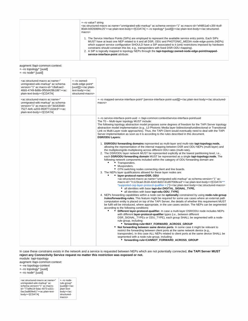
The Service Interface Points (SIPs) are employed to represent the available service entry points. Each SIPs MUST have at least one NEP related to it and all DSR, ODU and PHOTONIC_MEDIA node-edge-points (NEPs) which support service configuration SHOULD have a SIP associated to it (only restrictions imposed by hardware constrains should constrain this list, e.g., transponders with fixed DSR-ODU mapping).A SIP is logically mapped to topology NEPs through the tapi-topology:owned-node-edge-point/mapped-
attribute:service-interface-point
augment /tapi-common:context:+--ro topology* [uuid]+--ro node* [uuid]
<ac:structured-macro ac:name="unmigrated-wiki-markup" ac:schema-version="1" ac:macro-id="c8afcae2-46b5-4749-8d6b-0f50d428b186"><ac:plain-text-body><![CDATA[
+--ro owned-node-edge-point* [uuid]]]></ac:plain-text-body></ac:structured-macro>
<ac:structured-macro ac:name="unmigrated-wiki-markup" ac:schema-version="1" ac:macro-id="3d1630d0-7527-4efc-a203-950f77132dc9"><ac:plain-text-body><![CDATA[
+--ro mapped-service-interface-point* [service-interface-point-uuid]]]></ac:plain-text-body></ac:structured-macro>
+--ro service-interface-point-uuid -> /tapi-common:context/service-interface-point/uuid The T0 – Multi-layer topology MUST include:The following topology abstraction model proposes some degrees of freedom for the TAPI Server topology abstraction model implementation (e.g., L0 Photonic Media layer bidirectional/unidirectional or Transitional Link vs Multi-Layer node approaches). Thus, the TAPI Client would eventually need to deal with the TAPI Server implementation as soon as it is according to the rules described in this document.DSR/ODU Layers:
DSR/ODU forwarding domains represented as multi-layer and multi-rate ,tapi-topology:nodeallowing the representation of the internal mapping between DSR and ODU NEPs (multi-layer) and the multiplexing/de-multiplexing across different ODU rates (multi-rate).The DSR/ODU layer network MUST be represented explicitly at the lowest partitioning level, i.e., each MUST be represented as a single The DSR/ODU forwarding domain tapi-topology:node.following network components included within the category of ODU forwarding domain are:
Transponders.Muxponders.OTN switching nodes connecting client and line boards.
The NEPs layer qualifications allowed for these layer nodes are:layer-protocol-name=DSR, ODU<ac:structured-macro ac:name="unmigrated-wiki-markup" ac:schema-version="1" ac:macro-id="7c123cad-2b18-42e0-8d22-61d97f306ca3"><ac:plain-text-body><![CDATA***
]></ac:plain-text-body></ac:structured-macro>*supported-cep-layer-protocol-qualifier = [*all identities with base tapi-dsr:DIGITAL_SIGNAL_TYPE,all identities with base ]tapi-odu:ODU_TYPE
NEPs forwarding capabilities within a node can be constrained by using optionally node-rule-group This feature might be required for some use cases where an external path /rules/forwarding-rules.
computation entity is placed on top of the TAPI Server, the details of whether this requirement MUST be fulfil will be introduced, where appropriate, in the use cases section. The NEPs can be segmented according to the following conditions:
Different layer-protocol-qualifier. In case a multi-layer DSR/ODU node includes NEPs with different types (i.e., between different layer-protocol-qualifierDSR_SIGNAL_TYPEs or ODU_TYPE), each group SHALL be segmented with a node-rule-group, including:
forwarding-rule=MAY_FORWARD_ACROSS_GROUPNot forwarding between same device ports. In some case it might be relevant to restrict the forwarding between client ports at the same network device (e.g., transponder). In this case ALL NEPs related to client ports at the same device SHALL be segmented with a node-rule-group, including:
forwarding-rule=CANNOT_FORWARD_ACROSS_GROUP
In case these constrains exists in the network and a service is requested between NEPs which are not potentially connected, the TAPI Server MUST reject any Connectivity Service request no matter this restriction was exposed or not.module: tapi-topologyaugment /tapi-common:context:+--rw topology-context +--ro topology* [uuid]+--ro node* [uuid]
<ac:structured-macro ac:name="unmigrated-wiki-markup" ac:schema-version="1" ac:macro-id="77a9fe19-5dac-4073-a321-0ac2ad809e61"><ac:plain-text-body><![CDATA[
+--ro node-rule-group* [uuid]]]></ac:plain-text-body></ac:structured-macro>
1.
<ac:structured-macro ac:name="unmigrated-wiki-markup" ac:schema-version="1" ac:macro-id="70d2deb6-a63a-4e6b-ad67-a0112dfafcc4"><ac:plain-text-body><![CDATA[
+--ro rule* [local-id]]]></ac:plain-text-body></ac:structured-macro>
+--ro rule-type? rule-type
+--ro forwarding-rule? forwarding-rule
+--ro override-priority? uint64
+--ro local-id string
<ac:structured-macro ac:name="unmigrated-wiki-markup" ac:schema-version="1" ac:macro-id="a13e3ea5-eb2c-4c3e-974d-8c3d699889b7"><ac:plain-text-body><![CDATA[
+--ro name* [value-name]]]></ac:plain-text-body></ac:structured-macro>
+--ro value-name string
+--ro value? string
<ac:structured-macro ac:name="unmigrated-wiki-markup" ac:schema-version="1" ac:macro-id="13a8a3b0-4180-4f69-9923-d592ec81ece6"><ac:plain-text-body><![CDATA[
+--ro node-edge-point* [topology-uuid node-uuid node-edge-point-uuid]]]></ac:plain-text-body></ac:structured-macro>
+--ro topology-uuid -> /tapi-common:context/tapi-topology:topology-context/topology/uuid
+--ro node-uuid -> /tapi-common:context/tapi-topology:topology-context/topology/node/uuid
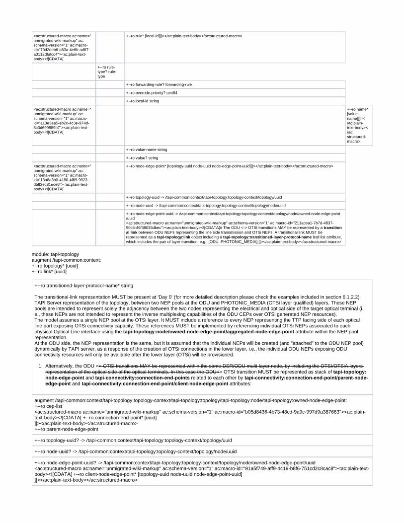
+--ro node-edge-point-uuid -> /tapi-common:context/tapi-topology:topology-context/topology/node/owned-node-edge-point/uuid <ac:structured-macro ac:name="unmigrated-wiki-markup" ac:schema-version="1" ac:macro-id="211acea1-7b7d-4837-90c5-46f38035dbec"><ac:plain-text-body><![CDATA[# The ODU <-> OTSI transitions MAY be represented by a transition
between ODU NEPs representing the line side transmission and OTSi NEPs. A transitional link MUST be al linkrepresented as a object including a leaf-list attribute, tapi-topology:link tapi-topology:transitioned-layer-protocol-namewhich includes the pair of layer transition, e.g., [ODU, PHOTONIC_MEDIA].]]></ac:plain-text-body></ac:structured-macro>
module: tapi-topologyaugment /tapi-common:context:+--ro topology* [uuid] +--ro link* [uuid]
+--ro transitioned-layer-protocol-name* string
The transitional-link representation MUST be present at 'Day 0' (for more detailed description please check the examples included in section 6.1.2.2) TAPI Server representation of the topology, between two NEP pools at the ODU and PHOTONIC_MEDIA (OTSi layer qualified) layers. These NEP pools are intended to represent solely the adjacency between the two nodes representing the electrical and optical side of the target optical terminal (i.e., these NEPs are not intended to represent the inverse multiplexing capabilities of the ODU CEPs over OTSi generated NEP resources).The model assumes a single NEP pool at the OTSi layer. It MUST include a reference to every NEP representing the TTP facing side of each optical line port exposing OTSi connectivity capacity. These references MUST be implemented by referencing individual OTSi NEPs associated to each physical Optical Line interface using the attribute within the NEP pool tapi-topology:node/owned-node-edge-point/aggregated-node-edge-pointrepresentation.At the ODU side, the NEP representation is the same, but it is assumed that the individual NEPs will be created (and "attached" to the ODU NEP pool) dynamically by TAPI server, as a response of the creation of OTSi connections in the lower layer, i.e., the individual ODU NEPs exposing ODU connectivity resources will only be available after the lower layer (OTSi) will be provisioned.
Alternatively, the ODU <> OTSI transitions MAY be represented within the same DSR/ODU multi-layer node, by including the OTSI/OTSiA layers > OTSI transition MUST be represented as stack of representation of the optical side of the optical terminals. In this case the ODU< tapi-topology:
and related to each other by node-edge-point tapi-connectivity:connection-end-points tapi-connectivity:connection-end-point/parent-node- and attributes:edge-point tapi-connectivity:connection-end-point/client-node-edge-point
augment /tapi-common:context/tapi-topology:topology-context/tapi-topology:topology/tapi-topology:node/tapi-topology:owned-node-edge-point: +--ro cep-list <ac:structured-macro ac:name="unmigrated-wiki-markup" ac:schema-version="1" ac:macro-id="b05d8436-4b73-48cd-9a9c-997d9a387663"><ac:plain-text-body><![CDATA[ +--ro connection-end-point* [uuid] ]]></ac:plain-text-body></ac:structured-macro>+--ro parent-node-edge-point
+--ro topology-uuid? -> /tapi-common:context/tapi-topology:topology-context/topology/uuid
+--ro node-uuid? -> /tapi-common:context/tapi-topology:topology-context/topology/node/uuid
+--ro node-edge-point-uuid? -> /tapi-common:context/tapi-topology:topology-context/topology/node/owned-node-edge-point/uuid <ac:structured-macro ac:name="unmigrated-wiki-markup" ac:schema-version="1" ac:macro-id="91a5f749-aff9-4419-b8f6-751cd2c8cac8"><ac:plain-text-body><![CDATA[ +--ro client-node-edge-point* [topology-uuid node-uuid node-edge-point-uuid] ]]></ac:plain-text-body></ac:structured-macro>

1.
2.
3. 4.
5.
6.
7.
1.
2.
1.
1.
+--ro topology-uuid -> /tapi-common:context/tapi-topology:topology-context/topology/uuid
+--ro node-uuid -> /tapi-common:context/tapi-topology:topology-context/topology/node/uuid
+--ro node-edge-point-uuid -> /tapi-common:context/tapi-topology:topology-context/topology/node/owned-node-edge-point/uuid
In case of the multi-layer nodes collapses the OTSi/OTSiA layer together with DSR and ODU layers into the same representation the tapi-topology:nodeNEPs CAN be qualified as:
tapi-photonic-media:PHOTONIC_LAYER_QUALIFER_OTSI,tapi-photonic-media:PHOTONIC_LAYER_QUALIFER_OTSIA,
Moreover, in case of the multi-layer node implementation, the following requirements' set, related to the OTSI PHOTONIC_MEDIA layer, MUST apply to the multi-layer node construct too.Please note, the TAPI Client MUST deal with both ODU-OTSI transition modelling approaches.OTSi/Photonic Media layers:
The OTSi layer represents the optical side of the optical terminals (transponders/muxponders). This layer consists of nodes representing the mapping and multiplexing of OTSi signals. It consists of nodes including OTSi client endpoints representing the Trail Termination Points (TTPs) of the OTSi connections and OTSi/OMS endpoints representing the physical connectivity with ROADM/FOADM add/drop ports. This optical line interfaces representation shall be available at 'Day 0' i.e., after the Optical Terminals commissioning stage and prior to any service deployment over the optical line interfaces. For more detail please check the examples included in section 6.1.2.2.The physical connectivity between transponder/muxponder line ports and ROADM/FOADM's add/drop ports MUST be represented as UNIDIRECTIONAL or BIDIRECTIONAL between tapi-topology:links PHOTONIC_MEDIA NEPs. These NEPs MUST be qualified as layer-
These NEPs represents the OTS and OMS switching layers and they protocol-qualifier: LAYER_PROTOCOL_QUALIFIER_UNSPECIFIED.should be the mounting point for any monitoring function in any of those layers.Independently of OMS NEPs directionality, the OTSI/OTSiA NEP representations on top of OMS NEP/CEPs MUST be BIDIRECTIONAL.OTSi NEPs MUST be present on top of OMS NEPs/CEPs to represent the effective forwarding of OTSi connections over the non-qualified PHOTONIC_MEDIA link between Transponder Line Ports and ROADM Add/Drop ports.The NEPs layer qualifications allowed nodes MUST be:within OTSi
layer-protocol-name= PHOTONIC_MEDIAsupported-cep-layer-protocol-qualifier= [PHOTONIC_LAYER_QUALIFIER_OTSi/OTSiA], [PHOTONIC_LAYER_QUALIFIER_UNSPECIFIED]
Each OTSi/OTSiA NEP MAY include the to represent the media channel pool tapi-photonic-media:media-channel-node-edge-point-specresources supportable, available and occupied.Generally, transponder/muxponder line ports and ROADM/FOADM's add/drop ports are 1:1 relation, in case Optical Line Protection (OLPs) are present, OLP complexity shall be always represented in the Photonic Media layer (for further description please see Use Case 5b).
Photonic-Media forwarding domains represents the Photonic Media (Open Line System (OLS)) network
The Photonic-Media forwarding domains can be mapped to OLP, ROADM/FOADM and ILA network elements which connectivity is always represented as PHOTONIC_MEDIA_UNSPECIFIED links (which may be augmented with OTS/OMS layers monitoring OAM functions). These forwarding domains SHALL expose the capability of create Media Channel connection and connectivity services between its endpoints.The NEPs layer qualifications allowed are:at the Photonic-Media forwarding domains (i.e., tapi-topology:node)
layer-protocol-name= PHOTONIC_MEDIAsupported-cep-layer-protocol-qualifier = [
PHOTONIC_LAYER_QUALIFIER_UNSPECIFIED, PHOTONIC_LAYER_QUALIFIER_MC,
.PHOTONIC_LAYER_QUALIFIER_OTSiMC]
Media Channel layer is consisting on Media-Channel (MC) constructs, representing a reserved portion of the spectrum to route the OTSi signals, and by the OTSiMC layer which represents the actual portion of the spectrum occupied by the signal (MC spectrum must be wider than the OTSiMC). Please see Figure 5-1 graphical representation for more clarity.
The MC layer MUST be represented by client NEPs/CEPs on top of the PHOTONIC_MEDIA_UNSPECIFIED (representing OTS/OMS layers) NEPs/CEPs at the OLS side of the links between Transponder Line Ports and ROADM Add/Drop ports. The OTSiMC layer MAY be optionally represented by client NEPs/CEPs on top of the PHOTONIC_LAYER_QUALIFER_MC CEPs. The representation of this layer does only provide monitoring information but not switching (which only happens at MC layer), thus its inclusion depends on the HW monitoring capabilities of the optical HW components of the network.
Figure 4-1 Media-channel entities relationship.

1.
2.
3.
Each MC, OTSiMC NEP MUST include the to represent the media channel pool tapi-photonic-media:media-channel-node-edge-point-specresources supportable, available and occupied.It is assumed at minimum, the lower layer forwarding constructs ( ) between forwarding domains ( ) which tapi-topology:link tapi-topology:nodeneed to be represented in this topology should be PHOTONIC_MEDIA_UNSPECIFIED links collapsing OTS and OMS layers. These links MUST
.be configured in the network in advance without being needed to be created during upper layer services provisioning processIn case OLP constructs are present for OMS or OTS protection, this should be represented in TAPI by using tapi-topology:resilience-type/tapi-
link's attribute. Underlying switch control for OMS or OTS protection is out of the scope of this modelling.topology:protection-type
Inventory considerations
Hardware identifiers currently stored in legacy OSS inventory systems MUST be correlated with T-API UUID identifiers. This information will be provided by the SDN optical domain controller suppliers as a pre-requisite for the use cases described in section 0 of the present document.For every inventory element represented as a logical element in TAPI by the SDN Domain controller, an property INVENTORY_ID tapi-common:nameshall be included into the logical element construct.The tag SHALL be included for the following TAPI objects:INVENTORY_ID
tapi-topology:node-edge-pointtapi-common:service-interface-point
The proposal for a common definition of the tag, follows 2 main principles and it is based on [TMF-814] naming standards:INVENTORY_ID
It is explicit and clear: there's no ambiguity to which field each index correspondIt can be augmented: if a new type of field needs to be inserted it does not break compatibility with the former format.
The generic format is the concatenation of tuple elements "/<field>=<index>"nThe supported fields for tuple elements are:
Table 4: Inventory-id fields format.
<field> meaning
ne Network Element
r Rack
sh Shelf
s_sh Sub-shelf
sl Slot
s_sl Sub-slot
p Port
The supported sequence for the tuple is the following and covers a variety of supported scenarios that may not all be applicable.
[ ] means that may not be present[ …] means that multiple values can be specified (marked as
green x in the matrix)
<span style="color: #141313"> </span>/ne=<nw-ne-name>[/r=<r_index>][/sh=<sh_index>[/s_sh=<s_sh_index> …]][[/sl=<sl_index>[/s_sl=<s_sl_index> …]][/p=<p_index> …]]
is the real name configured in the network (i.e. not managed by the SDN-C) and MUST be unique along <nw-ne-name> Network Element (NE)all exposed interfaces of the network control and management planes (i.e., Network Management Systems (NMSs) or Element Management Systems (EMSs) exposing network information).
is the real configured in the network (i.e. not managed by the SDN-C) and MUST be unique along all exposed interfaces <r_index> Rack indexof the network control and management planes (i.e., Network Management Systems (NMSs) or Element Management Systems (EMSs) exposing network information).
is the real configured in the network (i.e. not managed by the SDN-C) and MUST be unique along all exposed interfaces <sh_index> Shelf indexof the network control and management planes (i.e., Network Management Systems (NMSs) or Element Management Systems (EMSs) exposing network information).
is the real configured in the network (i.e. not managed by the SDN-C) and MUST be unique along all exposed <s_sh_index> Sub-Shelf indexinterfaces of the network control and management planes (i.e., Network Management Systems (NMSs) or Element Management Systems (EMSs) exposing network information).
is the real configured in the network (i.e. not managed by the SDN-C) and MUST be unique along all exposed interfaces <sl_index> Slot indexof the network control and management planes (i.e., Network Management Systems (NMSs) or Element Management Systems (EMSs) exposing network information).
is the real configured in the network (i.e. not managed by the SDN-C) and MUST be unique along all exposed <s_sl_index> Sub-Slot indexinterfaces of the network control and management planes (i.e., Network Management Systems (NMSs) or Element Management Systems (EMSs) exposing network information).
is the real configured in the network (i.e. not managed by the SDN-C) and MUST be unique along all exposed interfaces <p_index> Port indexof the network control and management planes (i.e., Network Management Systems (NMSs) or Element Management Systems (EMSs) exposing network information).

Meaning for the port the following possible combinations depicted in the following matrix.Each column represents which tuples can be after the element listed in the first column.
Table 5: Inventory-id fields combination allowance.
/r= <r_index>
/sh= <sh_index>
/s_sh= <s_sh_index>
/sl= <sl_index>
/s_sl= <s_sl_index>
/p= <p_index>
/ne=<nw-ne-name> X x - x - x
/r=<r_index> - x - x - -
/sh=<sh_index> - - x x - -
/s_sh=<s_sh_index> - - - x - -
/sl=<sl_index> - - - - x x
/s_sl=<s_sl_index> - - - - x x
/p=<p_index> - - - - - -
<span style="color: #141313"> </span><span style="color: #141313">Some examples of INVENTORY_ID for the node-edge-points potentially mapped to the ports described in the examples shown in Figure 6-25 in Section 6.4.2.2:</span>Example 1:"name": [{"value_name": "INVENTORY_ID", "value":"/ne=MadridNorte/r=1/sh=1/sl=1/s_sl=0"}] Example 2:"name": [{"value_name": "INVENTORY_ID", "value": "/ne=MadridNorte/r=1/sh=2/sl=2/s_sl=1/p=3"}] Example 3:"name": [{"value_name": "INVENTORY_ID", "value": "/ne=MadridNorte/r=1/sh=3/sl=7/s_sl=2/p=2"}]<ac:structured-macro ac:name="anchor" ac:schema-version="1" ac:macro-id="905caeac-257e-48f8-b39f-ba4b37fd22c7"><ac:parameter ac:name="">_Toc14454029</ac:parameter></ac:structured-macro><ac:structured-macro ac:name="anchor" ac:schema-version="1" ac:macro-id="8acd456a-7cd3-4942-a957-c384963327ec"><ac:parameter ac:name="">_Toc16163739</ac:parameter></ac:structured-macro>
Network scenarios
Now we introduce two network scenarios, as the base examples to clearly explain the model assumptions explained before.
Scenario 1: ROADM network equipped with OTN matrices
This first scenario represents a three-ROADM network equipped with OTN matrices to perform grooming of Ethernet 1G and 10G client signals into 100G line-side interfaces transmitting OTSi colored optical wavelengths.
Figure 4-2 NS-1: OTN/WDM Network scenario
Model representation (Transitional Link approach)
Please note, in the following representations, the OMS and OTS layers are present purely for information purposes. The specification has stated that these two layers are collapsed from the switching representation perspective. They are represented using PHOTONIC_LAYER_QUALIFIER_UNSPECIFIED layer-protocol-qualifier construct. Please find more details in [TAPI-TOP-MODEL-REQ-22].

Figure 4-3 NS-1. T0: TAPI Topology Flat Abstraction model, transitional link approach.
Figure 4-4 NS-1. T0: TAPI Topology Flat Abstraction model, transitional link approach (Device view).

Figure 4-5 NS-1.T0: TAPI Topology Flat Abstraction model multi-layer node approach.
Figure 4-6 NS-1.T0: TAPI Topology Flat Abstraction model multi-layer node approach (Device view).
Scenario 2: Point-to-point DWDM link + Mesh DWDM network
The second scenario consists of two separated networks: one network is a point-to-point DWDM link separated by 2 In-Line-Amplifiers (ILAs) and terminated in Fixed OADM structures consisting on Mux/Demux; and the second is a similar three-ROADM network this time equipped with Transponder/Muxponder cards, the two transponders present in the network are connected to a Line Side Optical Line Protection (OLP) structures to provide optical 1+1 protection resilient schema.

Figure 4-7 NS-2: OTN/WDM Network scenario 2.
Model representation
Figure 4-8 NS-2. T0: TAPI Topology Flat Abstraction Transitional Link model.

Figure 4-9 NS-2. T0: TAPI Topology Flat Abstraction Transitional Link model (Device view).
Figure 4-10 NS-2. T0: TAPI Topology Flat Abstraction Multi-Layer Node model.

1.
2.
3.
1.
Figure 4-11 NS-2. T0: TAPI Topology Flat Abstraction Multi-Layer Node model (Device view).
Connectivity service modelIn this chapter the complete connectivity service model will be described. The intention is to clarify some gaps which might not be clear just be reading the current description included in TAPI YANG models which need to be enhanced in order to provide a uniform understanding on the use of the TAPI information models. Thus, in this section a set of reference design guidelines are stated in order to constrain the possibilities or interpretations of the current proposed models. The topology absence model is excluded. TAPI model covers connectivity-service without connections but in this reference implementation agreement this option is not covered.
Model guidelines
The following guidelines MUST be met by all implementations following the current specification.
The solution exposing the proposed NBI based on RESCONF/TAPI MUST expose the capability of creating Connectivity-Service at all proposed network layers.
DSR Layer: Models a Digital Signal of an unspecified format. This value can be used when the intent is to represent a generic digital layer signal without making any statement on its format or overhead (processing) capabilities.ODU Layer: Models the ODU layer as per described in [ITU-T G.709].PHOTONIC_MEDIA Layer: Models the OTSi,/ OTSiA, and Media Channels (OTSIMC, MC) as per described in [ITU-T G.872].
The connectivity model MUST include the concept of which is defined as end-to-end connections between CEPs within the Top Connection,same layer which may belong to different Forwarding-Domains (TAPI Nodes). They can be either terminated ("infrastructure trails") or non-terminated (connecting client signals). Please see section 4.2.4.2 for more complete information.A MUST, after being successfully provisioned by the TAPI Server, always include a reference to all Top tapi-connectivity:connectivity-serviceConnection objects supporting/composing the CS between its Connectivity-Service-End-Points (CSEPs), within its tapi-connectivity:connectionconnection list ( ). These connections describe the end-to-end connectivity across the tapi-connectivity:connectivity-service/connectionnetwork at every network layers traversed by the connectivity-service (represented as the combination of the tapi-common:layer-protocol-nameand attributes).tapi-common: layer-protocol-qualifier
module: tapi-connectivityaugment /tapi-common:context:+--rw connectivity-context+--rw connectivity-service* [uuid]
<ac:structured-macro ac:name="unmigrated-wiki-markup" ac:schema-version="1" ac:macro-id="24bb95a3-f378-4125-aed6-a34738df6aae"><ac:plain-text-body><![CDATA[
+--ro connection* [connection-uuid]]]></ac:plain-text-body></ac:structured-macro>
+--ro connection-uuid -> /tapi-common:context/tapi-connectivity:connectivity-context/connection/uuid
The Top Connection object MUST represent how the requested service has been implemented within a network layer. It shall include the object containing tapi-connectivity:connection/routethe list of connection-end-points (CEPs) traversed by the service at that layer.
module: tapi-connectivityaugment /tapi-common:context:+--rw connectivity-context

1.
2.
1.
+--ro connection* [uuid]+--ro route* [local-id]
<ac:structured-macro ac:name="unmigrated-wiki-markup" ac:schema-version="1" ac:macro-id="1b355646-0c1f-46cb-a298-332970a37906"><ac:plain-text-body><![CDATA[
+--ro connection-end-point* [topology-uuid node-uuid node-edge-point-uuid connection-end-point-uuid]]]></ac:plain-text-body></ac:structured-macro>
+--ro topology-uuid -> /tapi-common:context/tapi-topology:topology-context/topology/uuid
+--ro node-uuid -> /tapi-common:context/tapi-topology:topology-context/topology/node/uuid
+--ro node-edge-point-uuid -> /tapi-common:context/tapi-topology:topology-context/topology/node/owned-node-edge-point/uuid
+--ro connection-end-point-uuid -> /tapi-common:context/tapi-topology:topology-context/topology/node/owned-node-edge-point/tapi-connectivity:cep-list/connection-end-point/uuid
+--ro local-id string
<ac:structured-macro ac:name="unmigrated-wiki-markup" ac:schema-version="1" ac:macro-id="db1e7f1d-fa32-4cee-a229-c3ed539d4675"><ac:plain-text-body><![CDATA[
+--ro name* [value-name]]]></ac:plain-text-body></ac:structured-macro>
+--ro value-name string
+--ro value? string
The is modelled as a YANG List object of CEPs which is, by the default, ordered by the system (i.e., tapi-connectivity:connection/routethe TAPI server which produces it). The TAPI Server SHALL maintain the logical order of the CEP, however the absolute source of truth, to infer the logical order of the connection-end-points within the Route object by the TAPI client by the knowledge of the Topology information (links) and the NEP and CEP associations, which MUST univocally represent the correct sequence of CEPs for each Top Connection.The Top Connection MUST include a reference to all the lower connections generated in the in the same network layer and rate. These references MUST be included within the list. Please note that the tapi-connectivity:connection/tapi-connectivity:lower-connectionuse of the lower-connection attribute is used to represent the partitioning of the Top Connection and does not introduce any layering relationship.
module: tapi-connectivityaugment /tapi-common:context:+--rw connectivity-context+--ro connection* [uuid]+--ro lower-connection* [connection-uuid]
+--ro connection-uuid -> /tapi-common:context/tapi-connectivity:connectivity-context/connection/uuid
Top Connections MAY represent two different cases:Non-terminated Top Connections: between CEPs with a parent-NEPs (tapi-topology:owned-node-edge-point/tapi-connectivity:cep-list
) directly associated to the SIPs which has been referenced by the Service-End-Points of the /connection-end-point/parent-node-edge-pointConnectivity-Service associated to this Top Connection.
augment /tapi-common:context/tapi-topology:topology-context/tapi-topology:topology/tapi-topology:node/tapi-topology:owned-node-edge-point:+--ro cep-list+--ro connection-end-point* [uuid]+--ro parent-node-edge-point
+--ro topology-uuid? -> /tapi-common:context/tapi-topology:topology-context/topology/uuid
+--ro node-uuid? -> /tapi-common:context/tapi-topology:topology-context/topology/node/uuid
+--ro node-edge-point-uuid? -> /tapi-common:context/tapi-topology:topology-context/topology/node/owned-node-edge-point/uuid
<ac:structured-macro ac:name="unmigrated-wiki-markup" ac:schema-version="1" ac:macro-id="a9beb06f-8413-4983-b1eb-94fa6d181261"><ac:plain-text-body><![CDATA[** : between CEPs representing Trail Termination Points (TTPs) which handover Infrastructure Trails as defined in [ITU-T g.805]a signal of a given layer to a higher layer. These CEPs also produce associated client-NEPs (tapi-topology:owned-node-edge-point/tapi-
), to represent the generated pool of resources at a higher network layer or rate. connectivity:cep-list/connection-end-point/client-node-edge-pointE.g., an ODUk CEP producing a lower order ODUj NEP or an ODUk CEP producing DSR NEP.]]></ac:plain-text-body></ac:structured-macro>
augment /tapi-common:context/tapi-topology:topology-context/tapi-topology:topology/tapi-topology:node/tapi-topology:owned-node-edge-point:+--ro cep-list+--ro connection-end-point* [uuid]+--ro client-node-edge-point* [topology-uuid node-uuid node-edge-point-uuid]
+--ro topology-uuid -> /tapi-common:context/tapi-topology:topology-context/topology/uuid
+--ro node-uuid -> /tapi-common:context/tapi-topology:topology-context/topology/node/uuid
+--ro node-edge-point-uuid -> /tapi-common:context/tapi-topology:topology-context/topology/node/owned-node-edge-point/uuid

1.
1.
1.
2.
1.
Multi-layer connectivity service provisioning and connection generation
<ac:structured-macro ac:name="unmigrated-wiki-markup" ac:schema-version="1" ac:macro-id="dc80943e-dabc-479b-8053-c5267d357aef"><ac:plain-text-body><![CDATA[In the proposed model, the TAPI server MUST include a reference to each layer Top Connection within the Connectivity Service's Connection list as stated in [TAPI-CONN-MODEL-REQ-3].]]></ac:plain-text-body></ac:structured-macro>The Connectivity Service routing across different layers MUST be inferred the Top-connections and its lower-connections, composing/supporting the connectivity-service (referenced within the list attribute) and by the tapi-topology <-> tapi-tapi-connectivity:connectivity-service/connectionconnectivity model relationships. These relationships are described in the following requirements:
Every layer-protocol or layer-protocol-rate transition MUST be represented as a stack of and tapi-topology:node-edge-point tapi-connectivity: related to each other by and connection-end-points tapi-connectivity:connection-end-point/parent-node-edge-point tapi-connectivity:
attributes:connection-end-point/client-node-edge-point
augment /tapi-common:context/tapi-topology:topology-context/tapi-topology:topology/tapi-topology:node/tapi-topology:owned-node-edge-point:+--ro cep-list+--ro connection-end-point* [uuid]+--ro parent-node-edge-point
+--ro topology-uuid? -> /tapi-common:context/tapi-topology:topology-context/topology/uuid
+--ro node-uuid? -> /tapi-common:context/tapi-topology:topology-context/topology/node/uuid
+--ro node-edge-point-uuid? -> /tapi-common:context/tapi-topology:topology-context/topology/node/owned-node-edge-point/uuid<ac:structured-macro ac:name="unmigrated-wiki-markup" ac:schema-version="1" ac:macro-id="f187b572-5c87-4fba-8449-6093f36baf71"><ac:plain-text-body><![CDATA[ +--ro client-node-edge-point* [topology-uuid node-uuid node-edge-point-uuid]]]></ac:plain-text-body></ac:structured-macro>
+--ro topology-uuid -> /tapi-common:context/tapi-topology:topology-context/topology/uuid
+--ro node-uuid -> /tapi-common:context/tapi-topology:topology-context/topology/node/uuid
+--ro node-edge-point-uuid -> /tapi-common:context/tapi-topology:topology-context/topology/node/owned-node-edge-point/uuid <ac:structured-macro ac:name="unmigrated-wiki-markup" ac:schema-version="1" ac:macro-id="80de4058-5453-4e54-8956-54d31d3a6346"><ac:plain-text-body><![CDATA[Please note that the previous statement is valid for all layer-protocol and layer-protocol-rate transitions but for the HO-ODUk <-> OTSi layer transition which MAY be represented also by a object including a tapi-topology:link tapi-topology:transitioned-layer-protocol-nameattribute as described in [TAPI-TOP-MODEL-REQ-10]. ]]></ac:plain-text-body></ac:structured-macro>
Additionally every object generated to represent the adjacency between every pair of NEPs connected by the sequence of tapi-topology:linkcross-connections included as lower-connections of a Top Connection object MUST be referenced by the tapi-connectivity:connection
attribute. The rest of the section states in which conditions these links SHALL be generated./supported-client-link
module: tapi-connectivityaugment /tapi-common:context:+--rw connectivity-context+--ro connection* [uuid]+--ro supported-client-link* [topology-uuid link-uuid]
+--ro topology-uuid -> /tapi-common:context/tapi-topology:topology-context/topology/uuid
+--ro link-uuid -> /tapi-common:context/tapi-topology:topology-context/topology/link/uuid Now, assuming a DSR Connectivity-Service has been requested between two SIPs associated to NEPs of the DSR layer, the multi-layer connections created are described by the following assumptions:At DSR layer:
The CS triggers the creation of the Top Connection at the DSR layer:Once DSR Top Connection is operational ( ), the DSR CS tapi-connectivity:connection/tapi-common:operational-state = ENABLEDbecomes operational too and includes DSR Top Connection within its connection list.DSR Top Connection MUST include the explicit route referencing CEPs associated to NEPs at the DSR layer.
One or more, DSR XC Connections, describing the lower partitioning level of DSR Top Connection and MUST be included within its lower-connection list.
When operational ( ), the DSR Top Connection becomes tapi-connectivity:connection/tapi-common:operational-state = ENABLEDoperational too.
the CS triggers the creation of:At the ODU layer
0-N Top Connections at the ODUj layers, which describes the multiplexing of Low Order (LO)-ODU signals into High Order (HO)-ODU signals.Once each 0-N Top Connections at the ODUj layers are operational (tapi-connectivity:connection/tapi-common:operational-state =
), all TOP connections MUST be included within the CS connection list.ENABLEDEach ODUj Top Connection MUST include the list of ODUj lower connections describing the lower partitioning level of ODUj Top Connection.When each ODUj Top Connection become operational ( ) tapi-connectivity:connection/tapi-common:operational-state = ENABLEDin increasing order from lower ODU layer (higher ODU rate) to the DSR layer, the immediately upper layer adjacency is enabled (a higher layer NEP is created "over" the operational CEP) allowing the upper layer Top Connection to be realized.

1.
1.
2.
1.
2.
1.
2.
1.
2.
Moreover, when all ODUj Top Connections are operational, a new at the DSR layer ( ) tapi-topology:link layer-protocol-name=DSR MA generated between the NEPs produced by the CEPs (Trail Termination Points) of the Top Most Connection with the Y be optionally
ODUj Layer rate and referenced by the attributetapi-connectivity: supported-client-link .
One Top Connection at the HO-ODUk rate, which describe the highest order ODU (supported by this node) which transport by the optical OTSi layer.
Once the HO-ODUk Top Connection is operational ( ), it tapi-connectivity:connection/tapi-common:operational-state = ENABLEDMUST be included within the CS connection list.When the HO-ODUk Top Connection become operational (tapi-connectivity:connection/tapi-common:operational-state = ENABLED) the lower-rate ODU layer adjacency is enabled ( client layer NEPs is created "over" the operational CEPs) allowing the upper layer Top Connection to be realized.
Possibly multiple HO-ODUk XC Connections, describing the lower partitioning level of DSR Top Connection and they MUST be included within its lower-connection list.
When all XCs become operational, the HO-ODUk Top Connection becomes operational too.
At the PHOTONIC_LAYER_QUALIFER_OTSI layer the CS triggers the creation of:
One or more Top Connection at the OTSi layer between the two NEPs supporting the HO-ODUk NEPs.Once the OTSi Top Connection is operational ( ), it MUST tapi-connectivity:connection/tapi-common:operational-state = ENABLEDbe included within the CS connection list.If the multi-layer node modelling approach defined in [TAPI-TOP-MODEL-REQ-11] is followed (OTSI<>ODU layer transition is represented by the NEPs <> CEPs stack relationship instead of transitional links) and related HO-ODUk NEPs are not present in the multi-layer node, then these NEPs MUST be generated to allow the HO-ODUk Top Connection to be realized.When the OTSi Top Connection becomes operational, an ODU between the related HO-ODUk NEPs tapi-topology:link MAY be
generated, representing the potential adjacency between these two NEPs at the HO-ODUk layer/rate. The new generated optionallylink MUST be referenced by the Top Connection, which realizes it, as a tapi-connectivity: supported-client-link.OTSi/OTSiA Top Connection MUST include the explicit route referencing CEPs associated to NEPs of PHOTONIC_MEDIA Layer with OTSI supported-layer-qualifier.
Possibly multiple OTSi/OTSiA, XC Connections, describing the lower partitioning level of OTSI Top Connection and MUST be included within its lower-connection list.
When operational, the OTSi/OTSiA Top Connection becomes operational too.If the multi-layer node modelling approach defined in [TAPI-TOP-MODEL-REQ-11] is followed (OTSI<>ODU layer transition is represented by the NEPs <> CEPs stack relationship instead of transitional links) OTSi XC Connections may not be generated, nor referenced by the lower-connection list. In this case, the Top Connection's route MUST consists of the CEPs referenced at tapi-
list.connectivity:connection/connection-end-point
, the CS triggers the creation of one or more PHOTONIC_LAYER_QUALIFER_MC and optionally a At the Photonic Media LayerPHOTONIC_LAYER_QUALIFER_OTSIMC Top Connections at the Media-Channel layer.
One MC Top Connection at the Photonic Media layer between the two CEPs supported by the MC NEPs facing the OTSi NEPs. At server PHOTONIC_MEDIA layer, the NEPs are linked by PHOTONIC_MEDIA_UNSPECIFIED link.
Once the MC Top Connection is operational ( ), it MUST be tapi-connectivity:connection/tapi-common:operational-state = ENABLEDincluded within the CS connection list.When the MC Top Connection becomes operational ( ), an tapi-connectivity:connection/tapi-common:operational-state = ENABLEDOTSi between the OTSi NEPs facing the MC NEPs generated, representing the potential tapi-topology:link MAY be optionallyadjacency between these two NEPs at the OTSi layer. Thus, allowing ALL OTSi Top Connections supported by the MC to be realized. The new generated link Please note this may not be generated in case of an Open Line System disaggregated scenario where OTSi
MUST be referenced by the CEPs of the Top Connection which layer NEP facing the MC NEPs are not managed by the TAPI Server.generates it as a tapi-connectivity:supported-client-link.MC Top Connection MUST include the explicit route referencing CEPs associated to NEPs of PHOTONIC_MEDIA Layer with MC supported-layer-qualifier.
Possibly multiple MC XC Connections, describing the lower partitioning level of MC Top Connection and MUST be included within its lower-connection list.
When all XC become operational, the MC Top Connection becomes operational too.
OTSiMC layer representation, including Top Connections, XCs and CEPs, is only required to represent monitoring capabilities at the filters but not switching (switching is just happening at the lower MC layer). Thus, the representation of the OTSiMC CEPs is optional and it depends upon the monitoring capabilities of the photonic_media layer filters at the OTSiMC level (signal positioning within the actual spectrum filtered MC).
One or more OTSiMC Top Connections (depending on the number of OTSI signals composing the OTSiA) at the Photonic Media layer between the two client NEPs generated by MC CEPs logically linked to PHOTONIC_MEDIA_UNSPECIFIED Add/Drop ports connected to the OT's line ports.
Once the each OTSiMC Top Connection is operational ( ), tapi-connectivity:connection/tapi-common:operational-state = ENABLEDthey MUST be included within the CS connection list.Each OTSiMC Top Connection MUST include the explicit route referencing CEPs associated to NEPs of PHOTONIC_MEDIA Layer with OTSiMC supported-layer-qualifier.
Possibly multiple OTSiMC XC Connections, describing the lower partitioning level of OTSiMC Top Connection and MUST be included within its lower-connection list.
OTSiMC CEPs are present for two purposes, forwarding and monitoring. In the photonic model is never relevant for forwarding (strict fate sharing with MC), but only for monitoring.
When all XC become operational, the OTSiMC Top Connection becomes operational too.
Following a complete generic example of a DSR connectivity-service is presented, to clearly identify the connection association hierarchy described by the previous set of requirements.

1.
{"context":{"connectivity-context":{"connectivity-service":[{"uuid":"CS_UUID","end-point":[{"local_id":"LOCAL_ID_A","service-interface-point":{"service-interface-point-uuid":"SIP_UUID_A"}}, {"local_id":"LOCAL_ID_B","service-interface-point":{"service-interface-point-uuid":"SIP_UUID_B"}}],"connection":[{"connection_uuid":"DSR_TOP_1"},{"connection-uuid":"ODUj_TOP_1"},…{"connection-uuid":"ODUj+N_TOP_N"},{"connection-uuid":"HO-ODUk_TOP_1"}, {"connection-uuid":"OTSi_TOP_1"},{"connection-uuid":"OTSIMC_TOP_1"},{"connection-uuid":"MC_TOP_1"}]}], "connection":[{"uuid": "DSR_TOP_1","lower-connection":[ {"connection-uuid":"DSR_XC_1"}, {"connection-uuid":"DSR_XC_2"}]},{"uuid": "ODUj_TOP_1","lower-connection":[ {"connection-uuid":"ODUj_XC_1"}, {"connection-uuid":"ODUj_XC_2"},]}, … (repeated for N ODUj layer rates) {"uuid": "ODUj_TOP_N","lower-connection":[ {"connection-uuid":"ODUj_XC_1"}, {"connection-uuid":"ODUj_XC_2"}, ]},{"uuid": "HO-ODUk_TOP_1","lower-connection":[ {"connection-uuid":"HO-ODUk_XC_1"}, {"connection-uuid":"HO-ODUk_XC_2"}]},{"uuid": "OTSi_TOP_1","lower-connection":[ {"connection-uuid":"OTSi_XC_1"}, {"connection-uuid":"OTSi_XC_2"}]}, {"uuid": "OTSiMC_TOP_1","lower-connection":[{"connection-uuid":"OTSiMC_XC_1"}, {"connection-uuid":"OTSiMC_XC_2"},…{"connection-uuid":"OTSiMC_XC_N"}]} , {"uuid": "MC_TOP_1","lower-connection":[{"connection-uuid":"MC_XC_1"}, {"connection-uuid":"MC_XC_2"},…{"connection-uuid":"MC_XC_N"}]} ]}}}
Resiliency mechanism at connectivity service
To implement different mechanism of protection the TAPI Server MUST support the following protection and restoration policies (tapi-topology:) at the Connectivity Service level:protection-type
ONE_PLUS_ONE_PROTECTIONONE_PLUS_ONE_PROTECTION_WITH_DYNAMIC_RESTORATIONONE_PLUS_ONE_PROTECTION_WITH_PRE_COMPUTED_RESTORATIONPERMANENT_ONE_PLUS_ONE_PROTECTIONONE_FOR_ONE_PROTECTIONDYNAMIC_RESTORATIONPRE_COMPUTED_RESTORATION
module: tapi-connectivityaugment /tapi-common:context:+--rw connectivity-context+--rw connectivity-service* [uuid]
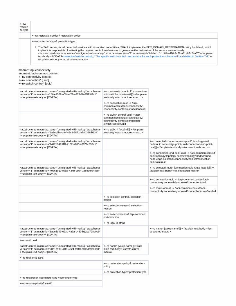
1.
+--rw resilience-type
+--rw restoration-policy? restoration-policy
+--rw protection-type? protection-type
The TAPI server, for all protected services with restoration capabilities, SHALL implement the PER_DOMAIN_RESTORATION policy by default, which implies it is responsible of activating the required control mechanisms to guarantee the restoration of the service autonomously.<ac:structured-macro ac:name="unmigrated-wiki-markup" ac:schema-version="1" ac:macro-id="6debe1c1-1b84-4d20-9a78-a81a05d2ea67"><ac:plain-text-body><![CDATA ]><connection/switch-control._* The specific switch-control mechanisms for each protection schema will be detailed in Section 7.4./ac:plain-text-body></ac:structured-macro>
module: tapi-connectivityaugment /tapi-common:context:+--rw connectivity-context+--rw connection* [uuid]+--ro switch-control* [uuid]
<ac:structured-macro ac:name="unmigrated-wiki-markup" ac:schema-version="1" ac:macro-id="d5ae4522-a09f-4f27-a273-1f46f1fb82c1"><ac:plain-text-body><![CDATA[
+--ro sub-switch-control* [connection-uuid switch-control-uuid]]]></ac:plain-text-body></ac:structured-macro>
+--ro connection-uuid -> /tapi-common:context/tapi-connectivity:connectivity-context/connection/uuid
+--ro switch-control-uuid -> /tapi-common:context/tapi-connectivity:connectivity-context/connection/switch-control/uuid
<ac:structured-macro ac:name="unmigrated-wiki-markup" ac:schema-version="1" ac:macro-id="6a8cc9be-df6f-45c3-9871-a78b328fb634"><ac:plain-text-body><![CDATA[
+--ro switch* [local-id]]]></ac:plain-text-body></ac:structured-macro>
<ac:structured-macro ac:name="unmigrated-wiki-markup" ac:schema-version="1" ac:macro-id="2442d947-ff1f-4102-a285-a397ffc838a1"><ac:plain-text-body><![CDATA[
+--ro selected-connection-end-point* [topology-uuid node-uuid node-edge-point-uuid connection-end-point-uuid]]]></ac:plain-text-body></ac:structured-macro>
+--ro connection-end-point-uuid -> /tapi-common:context/tapi-topology:topology-context/topology/node/owned-node-edge-point/tapi-connectivity:cep-list/connection-end-point/uuid
<ac:structured-macro ac:name="unmigrated-wiki-markup" ac:schema-version="1" ac:macro-id="49d61910-ebae-434b-9c04-18ee9fc6445b"><ac:plain-text-body><![CDATA[
+--ro selected-route* [connection-uuid route-local-id]]]></ac:plain-text-body></ac:structured-macro>
+--ro connection-uuid -> /tapi-common:context/tapi-connectivity:connectivity-context/connection/uuid
+--ro route-local-id -> /tapi-common:context/tapi-connectivity:connectivity-context/connection/route/local-id
+--ro selection-control? selection-control
+--ro selection-reason? selection-reason
+--ro switch-direction? tapi-common:port-direction
+--ro local-id string
<ac:structured-macro ac:name="unmigrated-wiki-markup" ac:schema-version="1" ac:macro-id="6aae3d49-623b-4a7a-b480-b12ca728e0bb"><ac:plain-text-body><![CDATA[
+--ro name* [value-name]]]></ac:plain-text-body></ac:structured-macro>
+--ro uuid uuid
<ac:structured-macro ac:name="unmigrated-wiki-markup" ac:schema-version="1" ac:macro-id="28e1d933-44f5-4324-b910-e805da9c8ba8"><ac:plain-text-body><![CDATA[
+--ro name* [value-name]]]></ac:plain-text-body></ac:structured-macro>
+--ro resilience-type
+--ro restoration-policy? restoration-policy
+--ro protection-type? protection-type
+--ro restoration-coordinate-type? coordinate-type
+--ro restore-priority? uint64

1.
+--ro reversion-mode? reversion-mode
+--ro wait-to-revert-time? uint64
+--ro hold-off-time? uint64
+--ro is-lock-out? boolean
+--ro is-frozen? boolean
+--ro is-coordinated-switching-both-ends? boolean
+--ro max-switch-times? uint64
+--ro preferred-restoration-layer* tapi-common:layer-protocol-name
Topology and service constrains for connectivity services
In order to implement different use cases that imply the constrain of the service path along the network topology, the following attributes of the tapi-onnectivity:connectivity-
object MUST be supported.service
module: tapi-connectivityaugment /tapi-common:context:+--rw connectivity-context+--rw connectivity-service* [uuid]
+--rw coroute-inclusion
+--rw connectivity-service-uuid? -> /tapi-common:context/tapi-connectivity:connectivity-context/connectivity-service/uuid
<ac:structured-macro ac:name="unmigrated-wiki-markup" ac:schema-version="1" ac:macro-id="3af06d44-9784-4e5b-b7e8-185c23f2b1b0"><ac:plain-text-body><![CDATA[
+--rw diversity-exclusion* [connectivity-service-uuid]]]></ac:plain-text-body></ac:structured-macro>
+--rw connectivity-service-uuid -> /tapi-common:context/tapi-connectivity:connectivity-context/connectivity-service/uuid
+--rw diversity-policy? diversity-policy
+--rw include-topology* tapi-common:uuid
+--rw avoid-topology* tapi-common:uuid
+--rw include-path* tapi-common:uuid
+--rw exclude-path* tapi-common:uuid
+--rw include-link* tapi-common:uuid
+--rw exclude-link* tapi-common:uuid
+--rw include-node* tapi-common:uuid
+--rw exclude-node* tapi-common:uuid
Use cases Low Level designs (LLDs)
Topology and services discoveryThis use case consists on retrieving all information available from TAPI servers (SDN-C) including service-interface-points and topology. Is intended to be performed by any NBI client controller, module or application which intends to discover the logical representation of the network done by the SDN-C. There are two modes of operations foreseen for this use case:
Pooling - based on periodic pooling retrieval operations and after each service creation to reconcile the modeactual state of the network.Event triggered - based on an initial proactive synchronization done from the NBI client mode (Notifications)module and a connection oriented notification subscription session based on the NBI Notification mechanism described in section 3.6 and 4.4.
In this version at least the pooling mechanism is foreseen to be fully supported by any provider SDN-C compliant with this specification.The use case is divided in two

Use Case 0a: Context & Service Interface Points discoveryUse Case 0b: Topology discovery
Use Case 0a: Context & Service Interface Points discovery (pooling mode)
Number UC0a
Name Context & Service Interface Points discovery (pooling mode)
Technologies involved
Optical
Process/Areas Involved
Planning and Operations
Brief description
The TAPI Context and Service Interface Points are the relevant network service information required before any connectivity-service creation operation. The discovery of this information is intended to be requested periodically and/or on-demand basis, proactively from the TAPI client role, to synchronize the context information.
Layers involved
DSR/ODU/PHOTONIC_MEDIA
Type Discovery
Description & Workflow
This use case consists on retrieving context and service-interface-point information (Figure 6-1). If the first operation (1) is correctly supported by the NBI server, it MUST retrieve the context filtered subtree up to three levels down into the hierarchy (2). The response operation MUST contain the attributes included in Table 7 which are marked as Mandatory (M) in the Support (Sup) column. The second operation (3) retrieves the list of service-interface-point (SIP) "uuid" (4), to recursively retrieve the full content of each SIP object in operation (5) which employs the "fields" query parameter to obtain only the desired filtered information. The response operation (6) MUST contain the attributes included in Table 8 which are marked as Mandatory (M) in the Support (Sup) column.
Figure 6-1 UC-0a: Context and Service Interface Point - LLD Workflow.
Required parameters
Following the required parameters for each object which is retrieved in this use case. Table 7: Context object definition
Context /tapi-common:context
Attribute Allowed Values/Format Mod Sup Notes
uuid "[0-9a-fA-F]{8} [0-9a-fA-F]{4} [[0-9a-fA-F]{4} [0-9a-fA-F]{4}0-9a-fA-F]{12}"
RO MAs per RFC 4122 Provided by tapi-server
name List of {value-name, value}
"value-name": "CONTEXT_NAME"
"value": " [0-9a-zA-Z_]{64}
"value-name": "VENDOR_NAME" "value": "[0-9a-zA-Z_]{64}"
RO MProvided by tapi-server CONTEXT_NAME is a user legible unstructured string tag to uniquely identify the tapi-server context. VENDOR_NAME is a user legible unstructured string tag to uniquely identify the tapi-server owner or supplier.
service-interface-point
List of {service-interface-point} RO MProvided by tapi-server Direct modification disallowed

notification-context
List of {notif-subscription} List of {notification}
RO OProvided by tapi-server
topology-context {network-topology-service} List of {topology}
RO MProvided by tapi-server
connectivity-context
List of {connectivity-service} List of {connection}
RO MProvided by tapi-server
Table 8: Service Interface Point (SIP) object definition
Service-interface-point /tapi-common:context/service-interface-point
Attribute Allowed Values/Format Mod
Sup
Notes
uuid"[0-9a-fA-F]{8} [0-9a-fA-F]{4} [0-9a-fA-F]{12}"[0-9a-fA-F]{4} [0-9a-fA-F]{4}
RW MAs per RFC 4122 Provided by tapi-server
name List of {value-name, value}
<span style="color: #141313">"value-name": "INVENTORY_ID",</span>
<ac:structured-macro ac:name="unmigrated-wiki-markup" ac:schema-version="1" ac:macro-id="e702cdef-45b7-4564-b0be-63a62e00b60c"><ac:plain-text-body><![CDATA[ "value": " [0-9a-zA-Z_]{64}"
RW MInitial value provided by tapi-server ]]></ac:plain-text-body></ac:structured-macro>INVENTORY_ID format is described in section 5.2 Subsequent updates provided by tapi-client
layer-protocol-name["DSR", "ETH", "ODU", "PHOTONIC_MEDIA"]
RO M
supported-layer-protocol-qualifierList of ["DIGITAL_SIGNAL_TYPE", "ODU_TYPE", "PHOTONIC_LAYER_QUALIFIER"]
RO MProvided by tapi-server All children identities defined for ["DIGITAL_SIGNAL_TYPE", "ODU_TYPE", "PHOTONIC_LAYER_QUALIFIER"] MUST be supported.
administrative-state["UNLOCKED", "LOCKED"]
RW MInitial value provided by tapi-server Subsequent updates provided by tapi-client
operational-state["ENABLED", "DISABLED"]
RO MProvided by tapi-server
lifecycle-state["PLANNED", "POTENTIAL_AVAILABLE", "POTENTIAL_BUSY", "INSTALLED", "PENDING_REMOVAL"]
RO MProvided by tapi-server
total-potential-capacity "total-size": {value, unit}
"value": "[0-9]{8}",
"unit": ["TB", "TBPS", "GB", "GBPS", "MB", "MBPS", "KB", "KBPS"]
RO MProvided by tapi-server
available-capacity "total-size": {value, unit}
"value": "[0-9]{8}",
"unit": ["TB", "TBPS", "GB", "GBPS", "MB", "MBPS", "KB", "KBPS"]
RO MProvided by tapi-server
tapi-photonic-media:otsi-service-interface-point-spec/ otsi-capability List of "supportable-central-frequency-spectrum-band":{ lower/upper-central-
frequency, frequency-constraint: {adjustment-granularity, grid-type} } "central-frequency": "
[0-9]{9}",
"adjustment-granularity":[ "UNCONSTRAINED", "G_3_125GHZ", "G_6_25GHZ", "G_12_5GHZ", "G_25GHZ", "G_50GHZ", "G_100GHZ",]
"grid-type": [ "GRIDLESS", "FLEX", "CWDM", "DWDM"]
List of "supportable-application-identifier":{ application-identifier-type, application-code}
"application-identifier-type":[ "PROPRIETARY", "ITUT_G959_1", "ITUT_G698_1", "ITUT_G698_2", "ITUT_G696_1", "ITUT_G695",]
"application-code": " [0-9a-zA-Z_]{64}"
List of "supportable-modulation":[ "RZ", "NRZ", "BPSK", "DPSK", "QPSK", "8QAM", "16QAM"]
"total-power-warn-threshold": {total-power-lower-warn-threshold-default /min/max, total-power-upper-warn-threshold-default /min/max"}
"total-power-*-warn-threshold": "[0-9].[0-9]{7}"
RO M Provided by tapi-server This block of attributes MUST augment SIPs attached to PHOTONIC_MEDIA NEPs exposing OTSI/OTSiG service provisioning capabilities. The lower/upper- of the laser specified in central-frequencyMHz. Those correspond to the lower and upper central frequencies of the band.
specify the rest of feasible central frequency-constraintfrequencies within the band.
in Gigahertz. As per ITU-T G.Adjustment-granularity694.1, it is used to calculate nominal central frequency". The specifies the reference set of frequencies grid-typeused to denote allowed nominal central frequencies that may be used for defining applications.
tapi-photonic-media:otsi-service-interface-point-spec/ power-management-capability "supportable-maximum-output-power":{total-power, power-spectral-density}
"Total-power":"[0-9].[0-9]{64}",
"power-spectral-density":"[0-9].[0-9]{64}"
"supportable-minimum-output-power":{total-power, power-spectral-density} "Total-power":"[0-9].[0-9]{64}",
RW M Provided by tapi-server Can be updated by the tapi-client

"power-spectral-density":"[0-9].[0-9]{64}"
"tolerable-maximum-output-power":{total-power, power-spectral-density} "Total-power":"[0-9].[0-9]{64}",
"power-spectral-density":"[0-9].[0-9]{64}"
"tolerable-minimum-output-power":{total-power, power-spectral-density} "Total-power":"[0-9].[0-9]{64}",
"power-spectral-density":"[0-9].[0-9]{64}"
tapi-photonic-media: media-channel-service-interface-point-spec/mc-pool List of "supportable/available/occupied-spectrum":{upper/lower-frequency, frequency-
constraint: {adjustment-granularity, grid-type} } "upper/lower-frequency": "
[0-9]{9}",
"adjustment-granularity":[ "UNCONSTRAINED", "G_3_125GHZ", "G_6_25GHZ", "G_12_5GHZ", "G_25GHZ", "G_50GHZ", "G_100GHZ",]
"grid-type": [ "GRIDLESS", "FLEX", "CWDM", "DWDM"]
RO M Provided by tapi-server This block of attributes MUST augment SIPs attached to PHOTONIC_MEDIA NEPs exposing Media_Channel service provisioning capabilities. The bound of the media channel upper/lower-frequencyspectrum specified in MHz..
in Gigahertz. As per ITU-T G.Adjustment-granularity694.1, it is used to calculate nominal central frequency". The specifies the reference set of frequencies grid-typeused to denote allowed nominal central frequencies that may be used for defining applications.
tapi-photonic-media: media-channel-service-interface-point-spec/power-management-capability
"supportable-maximum-output-power":{total-power, power-spectral-density} "Total-power":"[0-9].[0-9]{64}",
"power-spectral-density":"[0-9].[0-9]{64}"
"supportable-minimum-output-power":{total-power, power-spectral-density} "Total-power":"[0-9].[0-9]{64}",
"power-spectral-density":"[0-9].[0-9]{64}"
"tolerable-maximum-output-power":{total-power, power-spectral-density} "Total-power":"[0-9].[0-9]{64}",
"power-spectral-density":"[0-9].[0-9]{64}"
"tolerable-minimum-output-power":{total-power, power-spectral-density} "Total-power":"[0-9].[0-9]{64}",
"power-spectral-density":"[0-9].[0-9]{64}"
RW M Provided by tapi-server Can be updated by the tapi-client
Use Case 0b: Topology discovery (synchronous mode)
Number UC0b
Name Topology discovery (synchronous mode)
Technologies involved
Optical
Process/Areas Involved
Planning and Operations
Brief description
The TAPI Topology is the relevant network logical representation information required for inventory, traffic-engineering or provisioning purposes. The discovery of this information is intended to be requested periodically and/or on-demand basis, proactively from the TAPI client role, to synchronize the context information.
Layers involved
DSR/ODU/PHOTONIC_MEDIA
Type Discovery
Description & Workflow
The topology discover use case consists on the workflow and operations depicted in Figure 6-2. The first operation (1) retrieves the list of Topology references (UUID) included in the (2). For each Topology reference found, operation (3) is repeated to obtain a Topology object instance filtered tapi-topology:topology-context/nw-topology-service/subtree up to three levels (4). The details of the Topology object mandatory attributes are included in Table 9. The response operation MUST contain the attributes included in Table 9 which are marked as Mandatory (M) in the Support (Sup) column. For each node found in operation (4), operation (5) is repeated to retrieve each object (6) which MUST contain the attributes included in Table 10 which are tapi-topology:nodemarked as Mandatory (M) in the Support (Sup) column. Recursively, for each node object a filtered operation (7) is used to retrieve each reference. owned-node-edge-point/uuidFor each owned-node-edge-point reference discovered in operation (7), operation (9) is performed to retrieve each owned-node-edge-point object (10) for each node. Each ONEP object MUST contain the attributes included in Table 11 which are marked as Mandatory (M) in the Support (Sup) column. For each topology found in operation (4), operation (11) is repeated to retrieve each object (12) which MUST contain the attributes included in Table 14 which tapi-topology:linkare marked as Mandatory (M) in the Support (Sup) column.

Figure 6-2 UC-0b: Topology discovery - LLD Workflow.
Required parameters
Following we include the required parameters for each object which is retrieved in the previously described RESTCONF operations. Table 9: Topology object definition
Topology /tapi-common:context/tapi-topology:topology-context/topology
Attribute Allowed Values/Format Mod
Sup
Notes
uuid"[0-9a-fA-F]{8} [0-9a-fA-F]{4}[0-9a-fA-F]{4} [0-9a-fA-F]
[0-9a-fA-F]{12}"{4}
RO MAs per RFC 4122 Provided by tapi-server
name List of {value-name: value}
"value-name": "TOPOLOGY_NAME" "value": " [0-9a-zA-Z_]{64}"
RO MProvided by tapi-server TOPOLOGY_NAME is a user legible unstructured string tag to uniquely identify the tapi-server topology.
layer-protocol-name List of ["DSR", "ODU", "PHOTONIC_MEDIA"]
RO MProvided by tapi-server
link List of {link} RO MProvided by tapi-server

node List of {node} RO MProvided by tapi-server
Table 10: Node object definition
Node /tapi-common:context/tapi-topology:topology-context/topology/node
Attribute Allowed Values/Format Mod
Sup
Notes
uuid"[0-9a-fA-F]{8} [0-9a-fA-F]{4} [0-9a-fA-F]{12}"[0-9a-fA-F]{4} [0-9a-fA-F]{4}
RO MAs per RFC 4122 Provided by tapi-server
name List of {value-name: value}
"value-name": "NW-NE-NAME" "value": " [0-9a-zA-Z_]{64}"
RO MProvided by tapi-server NW-NE-NAME format is described in section 5.2
layer-protocol-nameList of ["DSR", "ODU", "PHOTONIC_MEDIA"]
RO MProvided by tapi-server
administrative-state["UNLOCKED", "LOCKED"]
RO MProvided by tapi-server
operational-state["ENABLED", "DISABLED"]
RO MProvided by tapi-server
lifecycle-state["PLANNED", "POTENTIAL_AVAILABLE", "POTENTIAL_BUSY", "INSTALLED", "PENDING_REMOVAL"]
RO MProvided by tapi-server
total-potential-capacity
"total-size": {value: unit}
"value": "[0-9]{8}",
"unit": ["TB", "TBPS", "GB", "GBPS", "MB", "MBPS", "KB", "KBPS"]
RO OProvided by tapi-server
available-capacity "total-size": {value: unit}
"value": "[0-9]{8}",
"unit": ["TB", "TBPS", "GB", "GBPS", "MB", "MBPS", "KB", "KBPS"]
RO OProvided by tapi-server
cost-characteristic List of {cost-name: cost-value}
"cost-name": "HOP_COUNT" "cost-value": "[0-9]{8}"
RO OProvided by tapi-server
latency-characteristic List of { traffic-property-name: fixed-latency-characteristic }
"traffic-property-name": "FIXED_LATENCY" "fixed-latency-characteristic": "[0-9]{8}"
RO OProvided by tapi-server
encapsulated-topology
{"topology-ref"} RO OProvided by tapi-server Needed if encapsulated-topology is supported
aggregated-node-edge-point
List of {"node-edge-point-ref"} RO OProvided by tapi-server Needed if encapsulated-topology is supported
owned-node-edge-point
List of {node-edge-point} RO MProvided by tapi-server See Table 11
node-rule-group List of {node-rule-group} RO OProvided by tapi-server See Table 12
Table 11: Node-edge-point object definition
Node-edge-point /tapi-common:context/tapi-topology:topology-context/topology/node/owned-node-edge-point
Attribute Allowed Values/Format Mod
Sup
Notes
uuid"[0-9a-fA-F]{8} [0-9a-fA-F]{4} [0-9a-fA-F]{12}"[0-9a-fA-F]{4} [0-9a-fA-F]{4}
RO MAs per RFC 4122 Provided by tapi-server
name List of {value-name: value}
<span style="color: #141313">"value-name": "INVENTORY_ID",</span>
<ac:structured-macro ac:name="unmigrated-wiki-markup" ac:schema-version="1" ac:
RO MProvided by tapi-server ]]></ac:plain-text-body></ac:structured-macro>INVENTORY_ID format is described in section 5.2

macro-id="e3bbb8e7-9f09-4470-a49b-d63b896013b5"><ac:plain-text-body><![CDATA[ "value": " [0-9a-zA-Z_]{64}"
layer-protocol-name ["DSR", "ODU", "PHOTONIC_MEDIA"]
RO MProvided by tapi-server
supported-cep-layer-protocol-qualifier
List of ["DIGITAL_SIGNAL_TYPE", "ODU_TYPE", "PHOTONIC_LAYER_QUALIFIER"] RO M
Provided by tapi-server All children identities defined for ["DIGITAL_SIGNAL_TYPE", "ODU_TYPE", "PHOTONIC_LAYER_QUALIFIER"] MUST be supported when applicable.
administrative-state["UNLOCKED", "LOCKED"]
RO MProvided by tapi-server
operational-state["ENABLED", "DISABLED"]
RO MProvided by tapi-server
lifecycle-state["PLANNED", "POTENTIAL_AVAILABLE", "POTENTIAL_BUSY", "INSTALLED", "PENDING_REMOVAL"]
RO MProvided by tapi-server
termination-state["LP_CAN_NEVER_TERMINATE", "LT_NOT_TERMINATED", "TERMINATED_SERVER_TO_CLIENT_FLOW", "TERMINATED_CLIENT_TO_SERVER_FLOW", "TERMINATED_BIDIRECTIONAL", "LT_PERMENANTLY_TERMINATED", "TERMINATION_STATE_UNKNOWN"]
RO OProvided by tapi-server
termination-direction ["BIDIRECTIONAL", "SINK", "SOURCE"]
RO MProvided by tapi-server
link-port-direction["BIDIRECTIONAL",
"INPUT","OUTPUT"]
RO MProvided by tapi-server
link-port-role["SYMMETRIC"]
RO OProvided by tapi-server
total-potential-capacity
"total-size": {value: unit}
"value": "[0-9]{8}",
"unit": ["TB", "TBPS", "GB", "GBPS", "MB", "MBPS", "KB", "KBPS"]
RO MProvided by tapi-server
available-capacity "total-size": {value: unit}
"value": "[0-9]{8}",
"unit": ["TB", "TBPS", "GB", "GBPS", "MB", "MBPS", "KB", "KBPS"]
RO MProvided by tapi-server
aggregated-node-edge-point
List of {node-edge-point-ref} RO OProvided by tapi-server
mapped-service-interface-point
List of {"/tapi-common:context/service-interface-point/uuid"} RO OProvided by tapi-server
cep-list List of {connection-end-point} RO MProvided by tapi-server
tapi-photonic-media: media-channel-node-edge-point-spec
"mc-pool": {supportable/available/occupied-spectrum}
List of "supportable/available/occupied-spectrum":{upper/lower-frequency, frequency-constraint: {adjustment-granularity, grid-type} }
"upper/lower-frequency": "
[0-9]{9}",
"adjustment-granularity":[ "UNCONSTRAINED", "G_3_125GHZ", "G_6_25GHZ", "G_12_5GHZ", "G_25GHZ", "G_50GHZ", "G_100GHZ",]
"grid-type": [ "GRIDLESS", "FLEX", "CWDM", "DWDM"]
RO O Provided by tapi-server This block of attributes MUST augment PHOTONIC_MEDIA NEPs exposing Media_Channel characteristics. The bound of the upper/lower-frequencymedia channel spectrum specified in MHz..
in Gigahertz. As Adjustment-granularityper ITU-T G.694.1, it is used to calculate nominal central frequency". The specifies the reference set of grid-typefrequencies used to denote allowed nominal central frequencies that may be used for defining applications.
tapi-odu:odu-node-edge-point-spec
"odu-pool":{client capacity, max-client-instances, max-client-size} RO OProvided by tapi-server
Table 12: Node-rule-group object definition
Node-rule-group
/tapi-common:context/tapi-topology:topology-context/topology/node/node-rule-group
Attribute Allowed Values/Format Mod Sup Notes
uuid"[0-9a-fA-F]{8} [0-9a-fA-F]{4} [0-9a-fA-F][0-9a-fA-F]{4} [0-9a-fA-F]{4}{12}"
RO MAs per RFC 4122 Provided by tapi-server
name List of {value-name: value}
"value-name": "NRG_NAME"
RO MProvided by tapi-server

"value": " [0-9a-zA-Z_]{64}"
node-edge-point List of {node-edge-point-ref} RO MProvided by tapi-server
rule List of {rule} RO MProvided by tapi-server See Table 13
Table 13: Rule object definition
Rule /tapi-common:context/tapi-topology:topology-context/topology/node/node-rule-group/rule
Attribute Allowed Values/Format Mod
Sup
Notes
local-id"[0-9a-zA-Z_]{32}"
RO MProvided by tapi-server
name List of {value-name: value}
"value-name": "RULE_NAME" "value": " [0-9a-zA-Z_]{64}"
RO MProvided by tapi-server
rule-type["FORWARDING"]
RO MProvided by tapi-server Support other rule types?
forwarding-rule ["MAY_FORWARD_ACROSS_GROUP", "MUST_FORWARD_ACROSS_GROUP",
"CANNOT_FORWARD_ACROSS_GROUP", "NO_STATEMENT_ON_FORWARDING"]
RO MProvided by tapi-server
Table 14: Link object definition
Link /tapi-common:context/tapi-topology:topology-context/topology/link
Attribute Allowed Values/Format Mod Sup Notes
uuid"[0-9a-fA-F]{8} [0-9a-fA-F]{4} [0-9a-fA-F]{12}"[0-9a-fA-F]{4} [0-9a-fA-F]{4}
RO MAs per RFC 4122 Provided by tapi-server
name List of {value-name: value}
"value-name": "LINK_NAME" "value": " [0-9a-zA-Z_]{64}"
RO MProvided by tapi-server
layer-protocol-nameList of ["DSR", "ODU", "PHOTONIC_MEDIA"]
RO M
administrative-state["UNLOCKED", "LOCKED"]
RO MProvided by tapi-server
operational-state["ENABLED", "DISABLED"]
RO MProvided by tapi-server
lifecycle-state["PLANNED", "POTENTIAL_AVAILABLE", "POTENTIAL_BUSY", "INSTALLED", "PENDING_REMOVAL"]
RO MProvided by tapi-server
direction["BIDIRECTIONAL"]
RO MProvided by tapi- server
total-potential-capacity "total-size": {value: unit}
"value": "[0-9]{8}",
"unit": ["TB", "TBPS", "GB", "GBPS", "MB", "MBPS", "KB", "KBPS"]
RO MProvided by tapi-server
available-capacity "total-size": {value: unit}
"value": "[0-9]{8}",
"unit": ["TB", "TBPS", "GB", "GBPS", "MB", "MBPS", "KB", "KBPS"]
RO MProvided by tapi-server
transitioned-layer-protocol-name
List of {layer-protocol-name} RO MProvided by tapi-server Only applicable to transitional-links.
cost-characteristic List of {cost-name: cost-value}
"cost-name": "HOP_COUNT" "cost-value": "[0-9]{8}"
RO O

latency-characteristic List of { traffic-property-name: fixed-latency-characteristic }
"traffic-property-name": "FIXED_LATENCY" "fixed-latency-characteristic": "[0-9]{8}"
RO O
Risk-characteristic List of {risk-characteristic-name: risk-identifier-list}
"risk-characteristic-name": ["SRLG", "SRNG"]
"risk-identifier-list": List of "[0-9a-zA-Z_]{64}"
RO O
node-edge-point List of }{" "node-edge-point-ref RO MProvided by tapi-server
Expected results
In this section we introduce the detail TAPI-Topology modelling expected at "Day 0" (i.e., after the commissioning stage of the network devices into the SDN-C, but before any service is configured).
UC0b - Example 0: TAPI topology representation at "day 0" following Transitional Link modelling approach
The detailed description of the assumptions assumed by the Reference Implementation to compose the Topology at Day '0' based on a Transitional-Link model, are described in [TAPI-TOP-MODEL-REQ-9].
Figure 6-3 TAPI topology representation at "day 0" following Transitional Link modelling approach.
UC0b - Example 0: TAPI topology representation at "day 0" following Multi-layer Node modelling approach

Figure 6-4 TAPI topology representation at "day 0" following Multi-layer Node modelling approach.
Use case 0c: Connectivity Service discovery (synchronous mode)
Number UC 0C
Name Connectivity Service discovery (synchronous mode)
Technologies involved
Optical
Process/Areas Involved
Planning and Operations
Brief description
The TAPI Connectivity Service is a relevant network service information required for the operation. The discovery of this information is intended to be requested periodically and/or on-demand basis, proactively from the TAPI client role, in order to synchronize the connectivity information.
Layers involved
DSR, ODU, PHOTONIC_MEDIA
Type Planning
Description & Workflow
The Use Case 0c: Connectivity Service discovery consists on the retrieve of a connectivity-service at the DSR/ODU/PHOTONIC_MEDIA layers and the retrieval of the generated connections information. The complete workflow is shown in Figure 6-5. The NBI Client first retrieves the connectivity-context trimmed by the ?fields=connectivity-service filter to retrieve all connectivity-services deployed in the TAPI Server (2). Then,
iteratively the information of each Connectivity-Service (3) is requested, and also its list of Connection references (5). For all Connection reference a Connection retrieval operation is performed to get the Connection object details (7).
The NBI server MUST return a valid object, if previous operations (4)(6)(8) succeed, which are compliant with the definition of the objects included in Table 15 (Connectivity-Service) and Table 17 (Connection). Please note the Connection object MUST include all attributes marked as Mandatory (M) in the Support (Sup) in all Connection sub-objects
defined in Table 18, Table 19, Table 20, Table 21, Table 22 and Table 23.

Figure 6-5 UC-0c: Connectivity Service - LLD Workflow.
Required parameters
For the details about the required parameters for each object retrieved in the previously described RESTCONF call operation, please refer to the UC1a Required Parameters Section 6.2.1.1
Unconstrained E2E Service Provisioning
Please note that this use case can divided in five sub use cases depending on the layer on which it is applied:
UC1a: Unconstrained DSR Service Provisioning single wavelength ( 100G).<UC1b: Unconstrained DSR Service Provisioning multi wavelength (beyond 100G).UC1c: Unconstrained ODU Service ProvisioningUC1d: Unconstrained PHOTONIC_MEDIA/OTSi Service ProvisioningUC1e: Unconstrained PHOTONIC_MEDIA/OTSiA Service ProvisioningUC1f: Unconstrained PHOTONIC_MEDIA/NMC Service Provisioning
UC1c is left to be considered in future version of this specification.The workflow definition and required parameters described in these sections applies to all the different sub-use cases but the results in terms of the number of connections generated are different depending on the layer to which the unconstrained connectivity-service has been requested.The main different between the different sub-use cases described here, is the selection of the Connectivity-Service-End-Points, i.e., the layer of their associated SIPs. Depending on this selection the connections generated in the network are up to a networking layer or another. E.g., for the provisioning of a the TAPI Server will only generates connection up to the PHOTONIC_MEDIA/OTSi network layer. PHOTONIC_MEDIA/OTSi Connectivity-Service,
Use case 1a: Unconstrained DSR Service Provisioning single wavelength (<100G).
Number
UC1a
Name Unconstrained DSR Service Provisioning single wavelength (<100G).
Technologies involved
Optical
Process/Areas Involved
Planning and Operations
The UC1 describes the provisioning of a instance between service-interface-points exposed by the TAPI-Server at the DSR networking layer. tapi-connectivity:connectivity-service T his service can include intermediate regeneration if necessary.
The underlying connection provisioning and management (including lower layer connections e.g., ODU, OTSi, NMC including intermediate regeneration connections if needed) is

Briefdescription
performed by the SDN Domain controller. The path of each lower layer connection (e.g., ODU or OCh/OTSi, OMS) across the network topology is calculated by the controller and the connection automatically provisioned. The "unconstrained" term refers that the TAPI-Client is not introducing any routing constraint in the service request, thus rely completely into the routing capabilities of the TAPI-Server to select the network resources employed to provide the desired service characteristics. Moreover, the TAPI-Client is not providing technology specific Traffic-Engineering constrains such time-slot selection at the ODU layer, or optical-spectrum selection for the routing of OTSi connections.
Layers involved
DSR/ODU/PHOTONIC_MEDIA
Type Provisioning
Description & Workflow
The Use Case 1: Connectivity Service provisioning consists on the creation of a connectivity-service between Service-Interface-Points at the DSR/ODU/PHOTONIC_MEDIA layers and the retrieval of the generated connections information. The complete workflow is shown in Figure 6-6.The first operation (1) triggers the creation of Connectivity-Service in the NBI Server. The TAPI server MUST accept any valid combination of the attributes marked as Mandatory (M) in
the Support (Sup) column of Table 15 and Table 16. If the operation is successful, the NBI server MUST return an http response message with the Location Header as specified in https: //www.w3.org/Protocols/rfc2616/rfc2616-sec9.html#sec9.5 .
Once the resource has been created (here a pooling or event-trigger mechanism need to be defined in order to reconciliate the information),) the NBI Client may retrieve all information of the Connectivity-Service (3), Connection list of references (5) and all its Connection objects (7). The NBI server MUST return a valid object, if previous operations (4)(6)(8) succeed,
which are compliant with the definition of the objects included in Table 15 (Connectivity-Service) and Table 17 (Connection). Please note the Connection object MUST include all attributes marked as Mandatory (M) in the Support (Sup) in all Connection sub-objects defined in Table 18, Table 19, Table 20, Table 21, Table 22 and Table 23.
Figure 6-6 UC-1: Unconstrained end-to-end service provisioning.
Required parameters
Table 15: Connectivity-service object definition
Connectivity-service /tapi-common:context/tapi-connectivity:connectivity-context/connectivity-service
Attribute Allowed Values/Format Mod Sup Notes
uuid"[0-9a-fA-F]{8} [0-9a-fA-F]{4} [0-9a-fA-F]{12}"[0-9a-fA-F]{4} [0-9a-fA-F]{4}
RW MAs per RFC 4122 Provided by tapi-client
name List of {value-name: value}
"value-name": "SERVICE_NAME" "value": " [0-9a-zA-Z_]{64}"
RW MProvided by tapi-client
administrative-state["UNLOCKED", "LOCKED"]
RW OProvided by tapi-client
operational-state["ENABLED", "DISABLED"]
RO MProvided by tapi-server
lifecycle-state["PLANNED", "POTENTIAL_AVAILABLE", "POTENTIAL_BUSY", "INSTALLED", "PENDING_REMOVAL"]
RO MProvided by tapi-server
requested-capacity "total-size": {value: ,unit:}
"value": "[0-9]{8}",
"unit": ["TB", "TBPS", "GB", "GBPS", "MB", "MBPS", "KB", "KBPS"]
RW MProvided by tapi-client

service-type["POINT_TO_POINT_CONNECTIVITY"]
RW O Provided by tapi-client Support P2P only
service-layerList of ["DSR", "ODU", "PHOTONIC_MEDIA"]
RW MProvided by tapi-client
preferred-transport-layerList of ["DSR", "ODU", "PHOTONIC_MEDIA"]
RW OProvided by tapi-client
connection List of {connection-ref - /tapi-common:context/tapi-connectivity:connectivity-context/connection/uuid} RO MProvided by tapi-server
end-point List of {connectivity-service-end-point} RW MProvided by tapi-client Min elements 2. See Table 16
Table 16: Connectivity-service-end-point object definition
Connectivity-service-end-point
/tapi-common:context/tapi-connectivity:connectivity-service/end-point
Attribute Allowed Values/Format Mod
Sup
Notes
local-id"[0-9a-zA-Z_]{32}"
RW MProvided by tapi-client
layer-protocol-name List of ["DSR", "ODU", "PHOTONIC_MEDIA"]
RW MProvided by tapi-client
supported-layer-protocol-qualifier List of ["DIGITAL_SIGNAL_TYPE", "ODU_TYPE",
"PHOTONIC_LAYER_QUALIFIER"]
RW MProvided by tapi-server All children identities defined for ["DIGITAL_SIGNAL_TYPE", "ODU_TYPE", "PHOTONIC_LAYER_QUALIFIER"] MUST be supported.
administrative-state ["UNLOCKED", "LOCKED"]
RW OProvided by tapi-client
operational-state["ENABLED", "DISABLED"]
RO OProvided by tapi-server
lifecycle-state["PLANNED", "POTENTIAL_AVAILABLE", "POTENTIAL_BUSY", "INSTALLED", "PENDING_REMOVAL"]
RO OProvided by tapi-server
direction["BIDIRECTIONAL", "INPUT", "OUTPUT"]
RW OProvided by tapi-client
role["SYMMETRIC", "TRUNK"]
RW OProvided by tapi-client Support only P2P
capacity "total-size": {value: unit}
"value": "[0-9]{8}",
"unit": ["TB", "TBPS", "GB", "GBPS", "MB", "MBPS", "KB", "KBPS"]
RW OProvided by tapi-client
service-interface-point
"/tapi-common:context/service-interface-point/uuid" RW MProvided by tapi-client
connection-end-point
List { connection-end-point} RO MProvided by tapi-server See Table 18
Table 17: Connection object definition
connection /tapi-common:context/tapi-connectivity:connection
Attribute Allowed Values/Format Mod
Sup
Notes
uuid"[0-9a-fA-F]{8} [0-9a-fA-F]{4} [0-9a-fA-F]{12}"[0-9a-fA-F]{4} [0-9a-fA-F]{4}
RO MAs per RFC 4122
Provided by tapi-server
name List of {value-name, value}
"value-name": "CONNECTION_NAME" "value": " [0-9a-zA-Z_]{64}"
RO MProvided by tapi-server

layer-protocol-name List of ["DSR", "ODU", "PHOTONIC_MEDIA"]
RO MProvided by tapi-client
operational-state ["ENABLED", "DISABLED"]
RO MProvided by tapi-server
lifecycle-state["PLANNED", "POTENTIAL_AVAILABLE", "POTENTIAL_BUSY", "INSTALLED", "PENDING_REMOVAL"]
RO MProvided by tapi-server
direction["BIDIRECTIONAL"]
RO MProvided by tapi- server Support UNIDIRECTIONAL?
lower-connection
List of {connectivity-ref - /tapi-common:context/tapi-connectivity:connectivity-context/connection/uuid} RO MProvided by tapi-server
connection-end-point
List of {"connection-end-point-ref - /tapi-common:context/tapi-topology:topology-context/topology/node/owned-node-edge-point /tapi-connectivity:cep-list/connection-end-point/uuid "}
RO MProvided by tapi-server
route List of { route } RO MProvided by tapi-server See Table 23
switch-control List of { switch-control } RO MProvided by tapi-server
supported-client-link
List of {link-ref - topology-uuid + link-uuid RO OProvided by tapi-server
Table 18: Connection-end-point object definition
Connection-end-point
/tapi-common:context/tapi-topology:topology-context/topology/node/owned-node-edge-point/tapi-connectivity:cep-list/connection-end-point
Attribute Allowed Values/Format Mod
Sup
Notes
uuid"[0-9a-fA-F]{8} [0-9a-fA-F]{4} [0-9a-fA-F]{12}"[0-9a-fA-F]{4} [0-9a-fA-F]{4}
RO MAs per RFC 4122 Provided by tapi-server
name List of {value-name: value}
"value-name": "CEP_NAME" "value": " [0-9a-zA-Z_]{64}"
RO MProvided by tapi-server
layer-protocol-nameList of ["DSR", "ODU", "PHOTONIC_MEDIA"]
RO M Provided by tapi-server
supported-layer-protocol-qualifier List of ["DIGITAL_SIGNAL_TYPE", "ODU_TYPE", "PHOTONIC_LAYER_QUALIFIER"]
RO MProvided by tapi-server All children identities defined for ["DIGITAL_SIGNAL_TYPE", "ODU_TYPE", "PHOTONIC_LAYER_QUALIFIER"] MUST be supported.
administrative-state["UNLOCKED", "LOCKED"]
RO MProvided by tapi-server
operational-state["ENABLED", "DISABLED"]
RO MProvided by tapi-server
lifecycle-state["PLANNED", "POTENTIAL_AVAILABLE", "POTENTIAL_BUSY", "INSTALLED", "PENDING_REMOVAL"]
RO MProvided by tapi-server
termination-state["LP_CAN_NEVER_TERMINATE", "LT_NOT_TERMINATED", "TERMINATED_SERVER_TO_CLIENT_FLOW", "TERMINATED_CLIENT_TO_SERVER_FLOW", "TERMINATED_BIDIRECTIONAL", "LT_PERMENANTLY_TERMINATED", "TERMINATION_STATE_UNKNOWN"]
RO MProvided by tapi-server
termination-direction["BIDIRECTIONAL", "SINK", "SOURCE"]
RO MProvided by tapi-server
connection-port-direction ["BIDIRECTIONAL","INPUT","OUTPUT"]
RO MProvided by tapi-server
connection-port-role["SYMMETRIC"]
RO MProvided by tapi-server

aggregated-connection-end-point
List of {node-edge-point-ref} RO OProvided by tapi-server
parent-node-edge-point
List of {node-edge-point-ref} RO MProvided by tapi-server
client-node-edge-point
List of {node-edge-point-ref} RO MProvided by tapi-server
tapi-odu:odu-connection-end-point-spec
{odu-connection-end-point-spec} RO OProvided by tapi-server MUST augment CEPs at the ODU layer See Table 19
tapi-photonic-media:otsi-connection-end-point-spec
{ otsi-connection-end-point-spec } RO OProvided by tapi-server MUST augment CEPs at the PHOTONIC_MEDIA layer with OTSI layer-protocol-qualifier. See Table 20
tapi-photonic-media:media-channel-connection-end-point-spec
{media-channel-connection-end-point-spec} RO OProvided by tapi-server MUST augment CEPs at the PHOTONIC_MEDIA layer with MC/OTSiMC layer-protocol-qualifier. See Table 22
tapi-photonic-media:ots-media-channel-connection-end-point-spec
{ots-media-channel-connection-end-point-spec} Provided by tapi-server MUST augment CEPs at the PHOTONIC_MEDIA layer with layer-protocol-qualifier:LAYER_PROTOCOL_QUALIFIER_UNSPECIFIED See Table 23
Table 19: ODU-Connection-end-point-spec object definition
odu-connection-end-point-spec
/tapi-common:context/tapi-topology:topology-context/topology/node/owned-node-edge-point/tapi-connectivity:cep-list/connection-end-point/tapi-odu:odu-connection-end-point-spec
Attribute Allowed Values/Format Mod
Sup
Notes
odu-common { odu-type, odu-rate, odu-rate-tolerance }
"odu-type": [ ODU_TYPE],
"odu-rate": [0-9]{12},
"odu-rate-tolerance": [0-9]{12},
RO MProvided by tapi-server All children identities defined for ["ODU_TYPE"] MUST be supported.
odu-rate-toleranceStandardized values are defined in Table 7-2/G.709
odu-term-and-adapter
{ opu-tributary-slot-list, auto-payload-type, configured-client-type, configured-mapping-type, accepted-payload-type, named-payload-
type, hex-payload-type}
opu-tributary-slot-size: ["1G25", "2G5" ]
auto-payload-type? boolean configured-client-type: [DIGITAL_SIGNAL_TYPE]
configured-mapping-type: ["AMP", "BMP", "GFP-F", "GMP", "TTP_GFP_BMP", "NULL"]
accepted-payload-type "named-payload-type": ["UNKNOWN", "UNINTERPRETABLE"]
"hex-payload-type": "[0-9]{64}",
fec-parameters : { pre-fec-ber, post-fec-ber, corrected-bytes, corrected-bits, uncorrectable-bytes, uncorrectable-bits}
"pre-fec-ber": "[0-9]{64}",
"post-fec-ber": "[0-9]{64}",
"corrected-bytes": "[0-9]{64}",
"corrected-bits": "[0-9]{64}",
"uncorrectable-bytes": "[0-9]{64}",
"uncorrectable-bits": "[0-9]{64}",
odu-cn-effective-time-slot: List of "[0-9]{64}"
RO MProvided by tapi-server Configured-client-type accepts any child identities defined for ["DIGITAL_SIGNAL_TYPE"]
odu-ctp {tributary-slot-list, tributary-port-number, accepted-msi}
tributary-slot-list : List of"[0-9]{64}"
tributary-port-number:"[0-9]{64}"
accepted-msi? string
RO MProvided by tapi-server

odu-protection
{aps-enable, aps-level}
aps-enable : Booleanaps-level: "[0-9]{64}"
RO OProvided by tapi-server
Table 20: otsi-connection-end-point-spec object definition
otsi-connection-end-point-spec
/tapi-common:context/tapi-topology:topology-context/topology/node/owned-node-edge-point/tapi-connectivity:cep-list/connection-end-point/tapi-photonic-media:otsi-connection-end-point-spec
Attribute Allowed Values/Format Mod
Sup
Notes
otsi-termination
{selected-central-frequency, selected-application-identifier, selected-modulation, selected-spectrum, transmitted-power, received-power, laser-properties}
RO MProvided by tapi-server
selected-central-frequency
{ central-frequency, frequency-constraint: {adjustment-granularity, grid-type} }
"central-frequency": "[0-9]{9}",
"adjustment-granularity":[ "UNCONSTRAINED", "G_3_125GHZ", "G_6_25GHZ", "G_12_5GHZ", "G_25GHZ", "G_50GHZ", "G_100GHZ",]
"grid-type": [ "GRIDLESS", "FLEX", "CWDM", "DWDM"]
RO MProvided by tapi-server The of the laser specified in central-frequencyMHz. It is the oscillation frequency of the corresponding electromagnetic wave.
in Gigahertz. As per Adjustment-granularityITU-T G.694.1, it is used to calculate nominal central frequency". The specifies the reference set of grid-typefrequencies used to denote allowed nominal central frequencies that may be used for defining applications.
selected-application-identifier
{ application-identifier-type, application-code}
"application-identifier-type":[ "PROPRIETARY", "ITUT_G959_1", "ITUT_G698_1", "ITUT_G698_2", "ITUT_G696_1", "ITUT_G695",]
"application-code":"[0-9a-zA-Z_]{64}"
RO MProvided by tapi-server
selected -modulation ["RZ", "NRZ", "BPSK", "DPSK", "QPSK", "8QAM",
"16QAM"]
RO MProvided by tapi-server
selected-spectrum
{lower-frequency, upper-frequency, frequency-constraint: {adjustment-granularity, grid-type} }
"upper/lower-frequency": "[0-9]{9}",
"adjustment-granularity":[ "UNCONSTRAINED", "G_3_125GHZ", "G_6_25GHZ", "G_12_5GHZ", "G_25GHZ", "G_50GHZ", "G_100GHZ",]
"grid-type": [ "GRIDLESS", "FLEX", "CWDM", "DWDM"]
RO MProvided by tapi-server The of the laser specified in central-frequencyMHz. It is the oscillation frequency of the corresponding electromagnetic wave.
in Gigahertz. As per Adjustment-granularityITU-T G.694.1, it is used to calculate nominal central frequency". The specifies the reference set of grid-typefrequencies used to denote allowed nominal central frequencies that may be used for defining applications.
transmited-power
{total-power, power-spectral-density}
"total-power":"[0-9].[0-9]{7}",
"power-spectral-density": "[0-9].[0-9]{7}",
RO MProvided by tapi-server
received-power
{total-power, power-spectral-density}
"total-power":"[0-9].[0-9]{7}",
"power-spectral-density": "[0-9].[0-9]{7}",
RO MProvided by tapi-server
laser-properties
{laser-status, laser-application-type, laser-bias-current, laser-temperature}
"laser-status": ["ON","OFF","PULSING", "UNDEFINED"]
"laser-application-type": ["PUMP", "MODULATED", "PULSE"]
"laser-bias-current": "[0-9].[0-9]{7}",
"laser-temperature": "[0-9].[0-9]{7}",
RO MProvided by tapi-server
Table 21: OTSI-Assembly-connection-end-point-spec object definition
otsi-assembly-connection-end-point-spec
/tapi-common:context/tapi-topology:topology-context/topology/node/owned-node-edge-point/tapi-connectivity:cep-list/connection-end-point/tapi-photonic-media:otsi-assembly-connection-end-point-spec
Attribute Allowed Values/Format
Mod
Sup
Notes

otsi-adapter"number-of-otsi": [0-9]{9}
RO OProvided by tapi-server
Table 22 media-channel-connection-end-point-spec object definition
media-channel-connection-end-point-spec
/tapi-common:context/tapi-topology:topology-context/topology/node/owned-node-edge-point/tapi-connectivity:cep-list/connection-end-point/tapi-photonic-media:media-channel-connection-end-point-spec
Attribute Allowed Values/Format Mod
Sup
Notes
media-channel {occupied-spectrum, measured-power-ingress, measured-power-egress} R0 M Mandatory only for PHOTONIC_LAYER_QUALIFIER_MC layer-protocol-qualified CEPs
occupied-spectrum {lower-frequency, upper-frequency, frequency-constraint}
"upper/lower-frequency": "[0-9]{9}",
"frequency-constraint": {adjustment-granularity, grid-type} "adjustment-granularity":[ "UNCONSTRAINED", "G_3_125GHZ", "G_6_25GHZ", "G_12_5GHZ", "G_25GHZ", "G_50GHZ", "G_100GHZ",]
"grid-type": [ "GRIDLESS", "FLEX", "CWDM", "DWDM"]
RO MProvided by tapi-client The upper/lower-frequency boundaries of
the band specified in MHz. in Gigahertz. As per Adjustment-granularity
ITU-T G.694.1, it is used to calculate nominal central frequency".
The specifies the reference set of grid-typefrequencies used to denote allowed nominal central frequencies
measured-power-ingress
{total-power, power-spectral-density}
"total-power":"[0-9].[0-9]{7}",
"power-spectral-density": "[0-9].[0-9]{7}",
RO MProvided by tapi-server
measured-power-egress
{total-power, power-spectral-density}
"total-power":"[0-9].[0-9]{7}",
"power-spectral-density": "[0-9].[0-9]{7}",
RO MProvided by tapi-server
Table 23 ots-media-channel-connection-end-point-spec object definition
ots-media-channel-connection-end-point-spec
/tapi-common:context/tapi-topology:topology-context/topology/node/owned-node-edge-point/tapi-connectivity:cep-list/connection-end-point/tapi-photonic-media:ots-media-channel-connection-end-point-spec
Attribute Allowed Values/Format Mod
Sup
Notes
ots-media-channel {occupied-spectrum, measured-power-ingress, measured-power-egress} R0 M Mandatory only for LAYER_PROTOCOL_QUALIFIER_UNSPECIFIED layer-protocol-qualified CEPs corresponding to OMS-OTS abstraction in the photonic_media layer
occupied-spectrum {lower-frequency, upper-frequency, frequency-constraint}
"upper/lower-frequency": "[0-9]{9}",
"frequency-constraint": {adjustment-granularity, grid-type} "adjustment-granularity":[ "UNCONSTRAINED", "G_3_125GHZ", "G_6_25GHZ", "G_12_5GHZ", "G_25GHZ", "G_50GHZ", "G_100GHZ",]
"grid-type": [ "GRIDLESS", "FLEX", "CWDM", "DWDM"]
RO MProvided by tapi-client The upper/lower-frequency boundaries of the band specified
in MHz. in Gigahertz. As per ITU-T G.694.1, Adjustment-granularity
it is used to calculate nominal central frequency".
The specifies the reference set of frequencies used grid-typeto denote allowed nominal central frequencies
measured-power-ingress
{total-power, power-spectral-density}
"total-power":"[0-9].[0-9]{7}",
"power-spectral-density": "[0-9].[0-9]{7}",
RO MProvided by tapi-server
measured-power-egress
{total-power, power-spectral-density}
"total-power":"[0-9].[0-9]{7}",
"power-spectral-density": "[0-9].[0-9]{7}",
RO MProvided by tapi-server
Table 23: Route object definition
route /tapi-common:context/tapi-connectivity:connection/route
Attribute Allowed Values/Format Mod
Sup
Notes

local-id"[0-9a-zA-Z_]{32}"
RO MProvided by tapi-server
name List of {value-name: value}
"value-name": "ROUTE_NAME" "value": " [0-9a-zA-Z_]{64}"
RO MProvided by tapi-server
connection-end-point
List of {"connection-end-point-ref - /tapi-common:context/tapi-topology:topology-context/topology/node/owned-node-edge-point /tapi-connectivity:cep-list/connection-end-point/uuid "}
RO MProvided by tapi-server
Table 24: otsia-connectivity-service-end-point-spec object definition
otsia-connectivity-service-end-point-spec
/tapi-common:context/tapi-connectivity:connectivity-service/end-point/otsia-connectivity-service-end-point-spec
Attribute Allowed Values/Format Mod
Sup
Notes
otsi-config List of {otsi-config [local-id]}
otsi-config:{central-frequency, spectrum, application-identifier, modulation, laser-control, transmit-power, total-power-warn-threshold-upper, total-power-warn-threshold-lower, local-id, name}
RW M Provided by tapi-client
number-of-otsi [0-9]{9}
RW M Provided by tapi-client
central-frequency central-frequency: "[0-9]{9}",
"frequency-constraint": {adjustment-granularity, grid-type}
"adjustment-granularity":[ "UNCONSTRAINED", "G_3_125GHZ", "G_6_25GHZ", "G_12_5GHZ", "G_25GHZ", "G_50GHZ", "G_100GHZ",]
"grid-type": [ "GRIDLESS", "FLEX", "CWDM", "DWDM"]
RW M Provided by tapi-client The of the laser central-frequencyspecified in MHz. It is the oscillation frequency of the corresponding electromagnetic wave.
in Adjustment-granularityGigahertz. As per ITU-T G.694.1, it is used to calculate nominal central frequency".
The specifies the grid-typereference set of frequencies used to denote allowed nominal central frequencies
spectrum {lower-frequency, upper-frequency, frequency-constraint}
"upper/lower-frequency": "[0-9]{9}",
"frequency-constraint": {adjustment-granularity, grid-type}
"adjustment-granularity":[ "UNCONSTRAINED", "G_3_125GHZ", "G_6_25GHZ", "G_12_5GHZ", "G_25GHZ", "G_50GHZ", "G_100GHZ",]
"grid-type": [ "GRIDLESS", "FLEX", "CWDM", "DWDM"]
RW M Provided by tapi-client The upper/lower-frequency bounda
ries of the band specified in MHz. in Adjustment-granularity
Gigahertz. As per ITU-T G.694.1, it is used to calculate nominal central frequency".
The specifies the grid-typereference set of frequencies used to denote allowed nominal central frequencies
application-identifier
{application-identifier-type, application-code}
"application-identifier-type":[ "PROPRIETARY", "ITUT_G959_1", "ITUT_G698_1", "ITUT_G698_2", "ITUT_G696_1", "ITUT_G695",]
"application-code":"[0-9a-zA-Z_]{64}"
RW M Provided by tapi-cl

ient
modulation ["RZ", "NRZ", "BPSK", "DPSK", "QPSK", "8QAM", "16QAM"]
RW M Provided by tapi-client
transmit-power {total-power, power-spectral-density}
"total-power":"[0-9].[0-9]{7}",
"power-spectral-density": "[0-9].[0-9]{7}",
RW M Provided by tapi-client
laser-control [FORCED-ON, FORCED-OFF, AUTOMATIC-LASER-SHUTDOWN, UNDEFINED]
RW O Provided by tapi-client
total-power-warn-threshold-upper
[0-9].[0-9]{7}
RW M Provided by tapi-client
total-power-warn-threshold-lower
[0-9].[0-9]{7}
RW M Provided by tapi-client
local-id "[0-9a-zA-Z_]{32}"
RW M Provided by tapi-client
name List of {value-name: value}
"value-name": "OTSI_CONN_NAME" "value": " [0-9a-zA-Z_]{64}"
RW M Pro

vided by tapi-server
Table 25: mca-connectivity-service-end-point-spec object definition
mca-connectivity-service-end-point-spec
/tapi-common:context/tapi-connectivity:connectivity-service/end-point/mca-connectivity-service-end-point-spec
Attribute Allowed Values/Format Mod
Sup
Notes
number-of-mc [0-9]{9}
RW M Provided by tapi-client
capacity {value: unit}
"value": "[0-9]{8}",
"unit": ["TB", "TBPS", "GB", "GBPS", "MB", "MBPS", "KB", "KBPS"]
RW M Provided by tapi-client
mc-config List of {otsi-config [local-id]}
otsi-config:{spectrum, power-management-config-pac }
RW M Provided by tapi-client
spectrum {lower-frequency, upper-frequency, frequency-constraint}
"upper/lower-frequency": "[0-9]{9}",
"frequency-constraint": {adjustment-granularity, grid-type}
"adjustment-granularity":[ "UNCONSTRAINED", "G_3_125GHZ", "G_6_25GHZ", "G_12_5GHZ", "G_25GHZ", "G_50GHZ", "G_100GHZ",]
"grid-type": [ "GRIDLESS", "FLEX", "CWDM", "DWDM"]
RW M Provided by tapi-client The upper/lower-frequency boundarie
s of the band specified in MHz. in Gigahertz. Adjustment-granularity
As per ITU-T G.694.1, it is used to calculate nominal central frequency".
The specifies the reference grid-typeset of frequencies used to denote allowed nominal central frequencies
power-management-config-pac
{intended-maximum-output-power, intended-minimum-output-power, expected-maximum-input-power, expected-minimum-input-power}
"intended-maximum-output-power":{total-power, power-spectral-density}
"Total-power":"[0-9].[0-9]{64}",
"power-spectral-density":"[0-9].[0-9]{64}"
"intended-minimum-output-power":{total-power, power-spectral-density}
"Total-power":"[0-9].[0-9]{64}",
"power-spectral-density":"[0-9].[0-9]{64}"
"expected-maximum-output-power":{total-power, power-spectral-density}
"Total-power":"[0-9].[0-9]{64}",
"power-spectral-density":"[0-9].[0-9]{64}"
"expected-minimum-output-power":{total-power, power-spectral-density}
"Total-power":"[0-9].[0-9]{64}",
"power-spectral-density":"[0-9].[0-9]{64}"
RW M Provided by tapi-client
local-id "[0-9a-zA-Z_]{32}"
RW M Provided by tapi-client
name List of {value-name: value}
"value-name": "OTSI_CONN_NAME" "value": " [0-9a-zA-Z_]{64}"
RW M Provided by tapi-server

Expected results
In the following subsections we include detail examples of the expected results after the successful provisioning of connectivity-services. Please note that all examples follow the rules detailed in section 5.1.1To show some detailed TAPI connectivity examples, first a simple legend of icons and basic arrangement is included in Figure 6-7.
Figure 6-7 TAPI Logical Termination Point Template – Basic Arrangements.
UC1a - Example 1: 10GE client signal over ODU2 over ODU4 (DSR-ODU Fixed Mapping, flexible ODU allocation)
The following diagrams illustrate a possible sequence of generation of the required TAPI topology and connectivity objects and its relationships according to the rules described in section 5.1.1. However, the internal TAPI server workflow MAY vary and, if notification or streaming services are available, the sequence of asynchronous notifications received by the TAPI client MAY be different.Thus, the objective of this and the subsequent examples detailing the use cases is to illustrate the object composition and most importantly to define the expected result after a connectivity-service provisioning.Please note, that in the following examples (all included examples in Section 6), a modelling simplification (represented by blue square) of the client interface (UNI) has been introduced. For the current version of the RIA, the modelling of the UNI client facing side interfaces is not yet covered in detail, so the actual implementation decisions are left to the vendor according to each individual HW capabilities. Thus, please consider the following examples as a guideline of representation the connectivity modelling of the network facing side (e.g., the representation of how the multiplexing of DSR signals over ODU
over OTSi shall be modelled). In the following figure we include the general assumed UNI simplifications represented in the examples included in this version of the RIA.The following figure represents different assumptions done in the UNI representation.
Option 1: Assumes there is not flexibility at the DSR layer but the fixed cross-connection (at DSR layer) are explicitly represented.Option 2: Assumes there is not flexibility at the DSR layer and the fixed cross-connection (at DSR layer) are not explicitly represented.Option 3: Assumes there is flexibility at the DSR layer.

Figure 6-8 UNI Modelling simplifications Please note, that the following versions of the RIA will address the UNI representation in detail so the previous simplifications may not be longer valid.
Figure 6-9 Connectivity Service 10GE client signal over ODU2 (DSR-ODU Fixed Mapping) over ODU4 over single OTSi – Transitional Link modelling

Figure 6-10 Connectivity Service 10GE client signal over ODU2 (DSR-ODU Fixed Mapping) over ODU4 over single OTSi – Multi-layer node modelling.
UC1a - Example 2: 1GE client signal over ODU0 over ODU2 over ODU4 (Fixed DSR-ODU mapping, flexible ODU allocation)
For simplification OTSi and Photonic Media layers have been omitted from this example, as it is the exact same case depicted in the previous example.
Figure 6-11 Connectivity Service 1GE client signal over ODU0 over ODU2 over ODU4 (Fixed DSR-ODU mapping, flexible ODU allocation)
UC1a - Example 3: 1GE client signal over ODU0 over ODU2 over ODU4 (Fixed DSR-ODU mapping, flexible ODU allocation) with intermediate ODU0 switching.

1.
2.
Figure 6-12 Connectivity Service 1GE client signal over ODU0 over ODU2 over ODU4 (Fixed DSR-ODU mapping, flexible ODU allocation) with intermediate ODU0 switching
UC1a - Example 4: 10GE client signal over ODU2 over ODU4 (Fixed DSR-ODU mapping, flexible ODU allocation) with intermediate transponder regeneration.
In this example introduces the intermediate regeneration (3R) of the optical channel (OTSi) into account from the modelling perspective. Please consider the following:The TAPI Server MAY or MAY NOT expose SIPs for the regeneration board OTSi/OTSiA:
The TAPI Server does not expose SIPs for the regeneration board OTSi/ OTSiA interfaces, thus these resources are only available to be consumed by the internal control plane for regeneration of a higher layer (ODU, DSR) client connectivity-service. Currently we assume this approach.The TAPI Server does expose SIPs for the regeneration board OTSi/OTSiA interfaces. So, the TAPI Server exposes to the user the creation of the two OTSi/ OTSiA connectivity services segments independently, to be used by higher layer services. Moreover, these SIPs also can be used
to constrain a HO-ODUk or higher layer connectivity-service to use this 3R point. In this case, the user MUST request a creation of a CS including (for a regenerated service with a single regeneration point) four CSEPs with references to aEND, zEND and intermediate regeneration SIPs, in the CS request.
Assuming the option a), the expected connectivity model result in terms of hierarchy of connections within the CS's connection list, SHALL include a single HO-ODUk supported by N-segments of OTSi/OTSiA connections represented as ODU links between every regeneration stage (in this example a single regeneration results into 2 OTSI/OTSiA segments).
Figure 6-13 Connectivity Service 10GE client signal over ODU2 over ODU4 (Fixed DSR-ODU mapping, flexible ODU allocation) with intermediate transponder regeneration.
Use Case 1b: Unconstrained DSR Service Provisioning multi wavelength (beyond 100G).

Number UC1b
Name Unconstrained DSR Service Provisioning multi wavelength (beyond 100G).
Technologies involved
Optical
Process/Areas Involved
Planning and Operations
Brief description
The UC1 describes the provisioning of a instance between service-interface-points exposed by the TAPI-Server at the DSR tapi-connectivity:connectivity-servicenetworking layer. This service can include intermediate regeneration if necessary.The underlying connection provisioning and management (including lower layer connections e.g., ODU, OTSi/OTSiA,MC/OTSiMC including intermediate regeneration connections if needed) is performed by the SDN Domain controller. The path of each lower layer connection (e.g., ODU or OCh/OTSi, OMS) across the network topology is calculated by the controller and the connection automatically provisioned. The "unconstrained" term refers that the TAPI-Client is not introducing any routing constraint in the service request, thus relays completely into the routing capabilities of the TAPI-Server to select the network resources employed to provide the desired service characteristics. Moreover, the TAPI-Client is not providing technology specific Traffic-Engineering constrains such time-slot selection at the ODU layer, or optical-spectrum selection for the routing of OTSi connections.
Layers involved
DSR/ODU/PHOTONIC_MEDIA
Type Provisioning
Description & Workflow
This UC is implemented following the same workflow described in "Description & Workflow" of UC1a described in section 6.2.1
Expected results
The connection generation follows the rules detailed in section 5.1.1. In this use case it is expected that originally, the ODU and PHOTONIC_MEDIA layers are connected through a transitional link or collapsed in a multi-layer node. This use case triggers the generation of an ODUcN Top Connection which is realize by N number of OTSi Top Connections required to transport the service. N Top OTSi Connctions are thus, generated over the same parent NEP (which only includes PHOTONIC_LAYER_QUALIFIER_OTSi within its sup
list). ported-layer-qualifierThe ODUcN CEPs must include the FEC attributes specified in ODU-Connection-end-point-spec object definition in Table 18. Please note that these attributes have been duplicated at the ODU layer from the ones defined at the OTSI-Assembly-connection-end-point-spec object definition in Table 21, its use at the OTSiA layer is not anymore recommended.Additionally, the model may include an OTSiA/OTSiG MEP for monitoring purposes, however the monitoring capabilities of the model will be described in next releases of this specification.Please see the detail graphical description according to the Transitional-link and Multi-Layer models in Figure 6-14 and Figure 6-15 respectively.
UC1b - Example 5: 200GE over ODUc2 connectivity-service over two OTSi/OTSiMC over a single physical (PHOTONIC-MEDIA_OMS) port. Transitional link.
Figure 6-14 200GE over ODUc2 connectivity-service over two OTSi/OTSiMC over a single physical (PHOTONIC-MEDIA_OMS) port (Transitional Link).
UC1b - Example 5: 200GE over ODUc2 connectivity-service over two OTSi/OTSiMC over a single physical (PHOTONIC-MEDIA_OMS) port. Multi-layer node.

Figure 6-15 200GE over ODUc2 connectivity-service over two OTSi/OTSiMC over a single physical (PHOTONIC-MEDIA_OMS) port (Multi-Layer Node).
Use case 1c: Unconstrained ODU Service Provisioning
[TO BE DEFINED]
Use case 1d: Unconstrained PHOTONIC_MEDIA/OTSi Service Provisioning
Number UC1d
Name Unconstrained PHOTONIC_MEDIA/OTSi Service Provisioning
Technologies involved
Optical
Process/Areas Involved
Planning and Operations
Brief description
The UC1 describes the provisioning of a instance between service-interface-points exposed by the TAPI-Server at the tapi-connectivity:connectivity-servicePHOTONIC_MEDIA networking layer. The underlying connection provisioning and management (including lower layer connections e.g., OTS, NMC including intermediate regeneration connections if needed) is performed by the SDN Domain controller. The path of each lower layer connection (e.g., OCh/OTSi, OMS) across the network topology is calculated by the controller and the connection automatically provisioned. The "unconstrained" term refers that the TAPI-Client is introducing any routing constraint in the service request, thus relays completely into the routing capabilities of the TAPI-Server to select the network resources employed to provide the desired service characteristics. Moreover, the TAPI-Client is not providing technology specific Traffic-Engineering constrains such time-slot selection at the ODU layer, or optical-spectrum selection for the routing of OTSi connections.
Layers involved
PHOTONIC_MEDIA
Type Provisioning
Description & Workflow
This UC is implemented following the same workflow described in "Description & Workflow" of UC1a described in section 6.2.1
Expected results
This use case requires the relevant Service Interface Points (SIPs) attached to the corresponding OTSI NEPs are available and exposed by the TAPI server.The connection generation MUST follows the rules detailed in section 5.1.1.
UC1d - Example 6: OTSi Single Wavelength Connectivity service provisioning. Transitional link approach

In this use case it is expected that originally, the ODU and PHOTONIC_MEDIA layers are connected through a transitional link. Please see the detail graphical description in Figure 6-16:
Figure 6-16 OTSi single lambda connectivity-service - Transitional link model.
UC1d - Example 7: OTSi Single Wavelength Connectivity service provisioning. Multi-layer node approach
In this use case it is expected that originally, the ODU and PHOTONIC_MEDIA layers integrated in a Multi-layer Node. Please see the detail graphical description in Figure 6-17:

Figure 6-17 OTSi single lambda connectivity-service - Multi-layer node approach.
Use case 1e: Unconstrained PHOTONIC_MEDIA/OTSiA Service Provisioning
Number UC1e
Name Unconstrained PHOTONIC_MEDIA/OTSi Service Provisioning
Technologies involved
Optical
Process/Areas Involved
Planning and Operations
Brief description
The UC1 describes the provisioning of a instance between service-interface-points exposed by the TAPI-Server at the tapi-connectivity:connectivity-servicePHOTONIC_MEDIA networking layer. The underlying connection provisioning and management (including lower layer connections e.g., OTS, NMC including intermediate regeneration connections if needed) is performed by the SDN Domain controller. The path of each lower layer connection (e.g., OCh/OTSi, OMS) across the network topology is calculated by the controller and the connection automatically provisioned. The "unconstrained" term refers that the TAPI-Client is introducing any routing constraint in the service request, thus relays completely into the routing capabilities of the TAPI-Server to select the network resources employed to provide the desired service characteristics. Moreover, the TAPI-Client is not providing technology specific Traffic-Engineering constrains such time-slot selection at the ODU layer, or optical-spectrum selection for the routing of OTSi connections.
Layers involved
PHOTONIC_MEDIA
Type Provisioning
Description & Workflow
This UC is implemented following the same workflow described in "Description & Workflow" of UC1a described in section 6.2.1
Expected results
This use case requires the relevant Service Interface Points (SIPs) attached to the corresponding OTSIA NEPs are available and exposed by the TAPI server.The connection generation follows the rules detailed in section 5.1.1. In this use case it is expected that originally, the ODU and PHOTONIC_MEDIA layers are connected through a transitional link. This case requires the generation of N number of OTSi Top Connections required to transport the service. N Top OTSi Connections are thus, generated over the same parent NEP (which only includes PHOTONIC_LAYER_QUALIFIER_OTSi within its list). supported-layer-qualifierAdditionally, the model may include an OTSiA/OTSiG MEP for monitoring purposes, however the monitoring capabilities of the model will be described in next releases of this specification.Please see the detail graphical description in Figure 6-18 and Figure 6-19.
UC1e - Example 8: OTSiA multi-wavelength connectivity-service.
Figure 6-18 OTSiA multi-wavelength connectivity-service (transitional link model abstraction).

Figure 6-19 OTSiA multi-wavelength connectivity-service (multi-layer node model abstraction).
Use case 1f: Unconstrained PHOTONIC_LAYER_QUALIFER_MC Service Provisioning
Number UC1f
Name Use case 1f: Unconstrained PHOTONIC_LAYER_QUALIFER_MC Service Provisioning
Technologies involved
Optical
Process/Areas Involved
Planning and Operations
Brief description
The UC1 describes the provisioning of a instance between service-interface-points exposed by the TAPI-Server at the PHOTONIC_LAYER_QUALIFER_MC tapi-connectivity:connectivity-servicenetworking layer. This service can not include intermediate regeneration. This use case is intended to define the way the TAPI Client can request the creation of a media-channel service which reserves a portion of optical spectrum across the PHOTONIC_MEDIA layer. This MC is generally wider than the OTSI occupied spectrum which is going to occupy it because it also includes the guardband between channels. The graphical representation of the relationship between MC,
OTSIMC and OTSI signal is depicted in Figure 6-20.
Figure 6-20 Media-channel entities relationship.
The underlying connection provisioning and management is performed by the SDN Domain controller. The path of each lower layer connection (e.g., OMS, OTS) across the network topology is calculated by the controller and the connection automatically provisioned.
The "unconstrained" term refers that the TAPI-Client is not allowed to introduce any routing constraint in the service request, thus relays completely into the routing capabilities of the TAPI-Server to select the network resources employed to provide the desired service characteristics.
Moreover, the TAPI-Client is not providing technology specific Traffic-Engineering constrains such spectrum-band selection for the MC connections. The PHOTONIC_MEDIA layer topology MUST be represented according to one of the following alternatives:
Bidirectional Topology abstraction. Unidirectional Topology abstraction.
Moreover, the Reconfigurable Optical Add Drop Multiplexers (ROADMs) Add/Drop ports MUST be represented as UNI interfaces with associated SIPs. The UNI interfaces MUST be represented according to one of the following alternatives:
Bidirectional UNI representation. Unidirectional UNI representation.
Please find more details in the following "Expected results" section. : The PHOTONIC_LAYER_QUALIFER_MCDISCLAIMER of TAPI v2.1.3 is equivalent to previous PHOTONIC_MEDIA_SMC of v2.1.2
Layers involved
PHOTONIC_MEDIA
Type Provisioning
Description & Workflow
This UC is implemented following the same workflow described in "Description & Workflow" of UC1a described in section 6.2.1

1. 2. 3.
Expected results
This use case accepts different variations according to the model directionality chosen to represent the PHOTONIC_MEDIA layer. The currently agreed solutions are three:
Full-bidirectional - UNI and PHOTONIC_MEDIA model.Mixed-scenario - UNI bidirectional and topology unidirectional.Full-unidirectional OLS scenario - UNI and PHOTONIC_MEDIA unidirectional
UC1f - Model 1: Full Bidirectional - UNI and PHOTONIC_MEDIA Topology
This choice corresponds to a solution exposed by the TAPI server where the relation between the Add/Drop directions of UNI interfaces is known by the TAPI server and the unidirectionality of the rest of the PHOTONIC_MEDIA layer is abstracted as a full-bidirectional topology. In this approach the MC UNI interfaces are represented as bidirectional SIPs associated to Add/Drop PHOTONIC_MEDIA NEPs.
In this model, it is expected the lower layer NEPs (PHOTONIC_MEDIA), representing the Optical Terminals (OTs - Transponders/Muxponders) line interfaces and the ROADMs Add/Drop interfaces, are connected through a PHOTONIC_MEDIA layer with PHOTONIC_MEDIA_UNSPECIFIED layer-
protocol-qualifier tapi-topology:link with a 1:1 relationship. The NEPs/CEPs and links at the bottom layer represents the OTS and OMS ITU-T switching layers, which SHALL be augmented by the necessary OAM monitoring capabilities of these layers.MC Connectivity-Services are bidirectional too with a single bidirectional Top Connection representing the end-to-end route across the PHOTONIC_MEDIA layer.Moreover, the MC Top Connection includes within the attribute the reference to the Cross-Connections (XCs) tapi-connectivity:lower-connection
between the bidirectional PHOTONIC_LAYER_QUALIFIER_MC CEPs mounted over the bidirectional MC NEPs.
Figure 6-21 Full Bidirectional - UNI and OMS bidirectional scenario.
UC1f - Model 2: Mixed Scenario - UNI bidirectional and OMS unidirectional
The second alternative corresponds to a mixed solution exposed by the TAPI server where the relation between the Add/Drop directions of UNI interfaces is known by the TAPI server and thus, the MC UNI interfaces are represented as bidirectional SIPs associated to the Add/Drop PHOTONIC_MEDIA NEPs.However, the PHOTONIC_MEDIA layer is abstracted as a unidirectional link topology.
In this model, it is expected that originally, the NEPs of PHOTONIC_MEDIA (supporting OTSi layer-protocol-qualifier CEPs) and PHOTONIC_MEDIA (supp orting MC layer-protocol-qualifier CEPs) are connected through a link with a 1:1 relationship at the PHOTONIC_MEDIA_UNSPECIFIED layer.
MC Connectivity-services are bidirectional with two references to the bidirectional Add/Drop SIPs. Once successfully provisioned, the Connectivity-Service MUST reference a single bidirectional Top Connection representing the end-to-end route across the PHOTONIC_MEDIA layer.
The MC Top Connections includes, within the attribute,tapi-connectivity:lower-connection the references to the two point-to-multipoint Cross- Connections (XCs) connecting the bidirectional Add/Drop UNI interfaces to the ROADM degree unidirectional interfaces. Then the route traverses the
remaining unidirectional PHOTONIC_MEDIA nodes till the far end. All XCs in the two directions MUST be included into the MC Top Connection lower-level connection list.
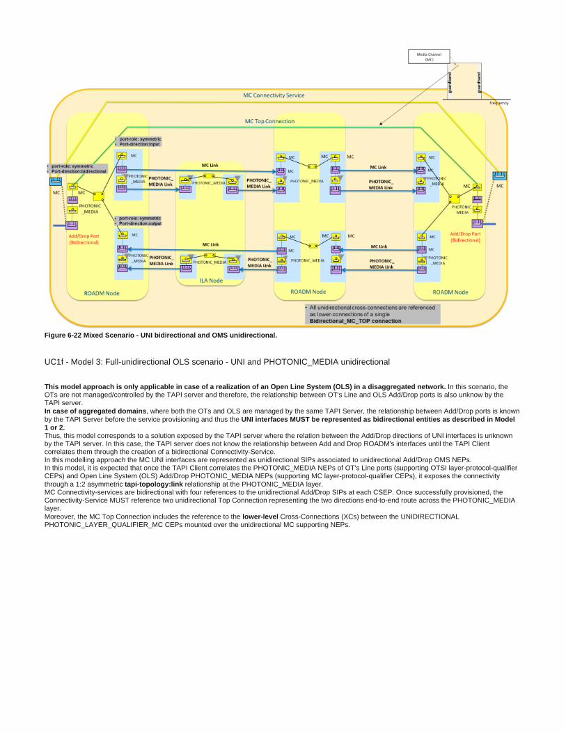
Figure 6-22 Mixed Scenario - UNI bidirectional and OMS unidirectional.
UC1f - Model 3: Full-unidirectional OLS scenario - UNI and PHOTONIC_MEDIA unidirectional
This model approach is only applicable in case of a realization of an Open Line System (OLS) In this scenario, the in a disaggregated network.OTs are not managed/controlled by the TAPI server and therefore, the relationship between OT's Line and OLS Add/Drop ports is also unknow by the TAPI server.
, where both the OTs and OLS are managed by the same TAPI Server, the relationship between Add/Drop ports is known In case of aggregated domainsby the TAPI Server before the service provisioning and thus the UNI interfaces MUST be represented as bidirectional entities as described in Model 1 or 2.Thus, this model corresponds to a solution exposed by the TAPI server where the relation between the Add/Drop directions of UNI interfaces is unknown
by the TAPI server. In this case, the TAPI server does not know the relationship between Add and Drop ROADM's interfaces until the TAPI Client correlates them through the creation of a bidirectional Connectivity-Service.
In this modelling approach the MC UNI interfaces are represented as unidirectional SIPs associated to unidirectional Add/Drop OMS NEPs. In this model, it is expected that once the TAPI Client correlates the PHOTONIC_MEDIA NEPs of OT's Line ports (supporting OTSI layer-protocol-qualifier
CEPs) and Open Line System (OLS) Add/Drop PHOTONIC_MEDIA NEPs (supporting MC layer-protocol-qualifier CEPs), it exposes the connectivity through a 1:2 asymmetric relationship at the PHOTONIC_MEDIA layer.tapi-topology:linkMC Connectivity-services are bidirectional with four references to the unidirectional Add/Drop SIPs at each CSEP. Once successfully provisioned, the Connectivity-Service MUST reference two unidirectional Top Connection representing the two directions end-to-end route across the PHOTONIC_MEDIA
layer.Moreover, the MC Top Connection includes the reference to the Cross-Connections (XCs) between the UNIDIRECTIONAL lower-level
PHOTONIC_LAYER_QUALIFIER_MC CEPs mounted over the unidirectional MC supporting NEPs.

Figure 6-23 Full Unidirectional - UNI and OMS unidirectional scenario.
Constrained Provisioning
Use case 3a: Include/exclude a node or group of nodes.
Number UC3a
Name Constrained provisioning: Include/exclude a node or group of nodes
Technologies involved
Optical
Process/Areas Involved
Planning and Operations
Brief description
This use case consists on the requests of a connectivity service between two Connectivity Service End Points associated to Service Interface points at different layers (DSR, ODU or OTSi). This service is subject to the inclusion/exclusion of the nodes selected by the TAPI client.
This service can include intermediate regeneration if necessary.This topology constrains MUST be processed as a LOOSE constrain and it SHOULD be considered desirable but not mandatory when enter in conflict with other
routing policies or re-routing condition such a restoration.The underlying connection generation (including lower layer connections e.g., OCh/OTSi, Photonic Media and regeneration nodes) is made by the SDN Domain controller. The route of each lower layer connection (e.g., OCh/OTSi, Photonic Media) across the network topology is calculated by the SDN Domain controller considering the constraints introduced in the service request. The route in each layer is recursively calculated from the lower layer to the upper layer, excluding/including of the ALL those componentstopology shared with the connections created to support the selected service. In case the topology-constrains (nodes) are applied to a service with restoration capabilities, any reroute action SHOULD account for any inclusion/exclusion topology-constrain policy defined if possible but, as a general rule, the restoration MUST always take place even if the topology-constrains enter in conflict with the new route.
Layers involved
DSR/ODU/PHOTONIC_MEDIA
Type Provisioning
Description & Workflow
The connectivity-service object sent by the TAPI Client to the Server to request the creation of the service MUST include the include-node or exclude-node attributes (node- uuid)
The node-uuid referenced by the attributes MUST be present in the TAPI Server context at the time of the CS provisioning is request. In case, the inclusion or exclusionreferenced CS element is invalid, the TAPI Server MUST return an error message in the RESTConf response message, according to the rules included in https://tools.ietf.org/html
, with the "invalid-value" <error-tag>. /rfc8040#section-7This UC is implemented following the same workflow described in "Description & Workflow" of UC1a described in section 6.2.1
Required parameters
Table 24 complements the information included in the Use Case 1a definition, with the Connectivity-Service attributes required to implement this use case, this implies all attributes and objects included in Section 6.2.1.1 tables is required for this use case too.

Table 26: Connectivity-service node topology-constrains object definitions.
connectivity-service
/tapi-common:context/tapi-connectivity:connectivity-context/connectivity-service
Attribute Allowed Values/Format Mod Sup Notes
include-node LeafList of {
"[0-9a-fA-F]{8} [0-9a-fA-F]{4} [0-9a-fA-F]{12}"[0-9a-fA-F]{4} [0-9a-fA-F]{4}
}
RW MThis is a loose constraint - that is it is unordered and could be a partial list
exclude-node LeafList of {
"[0-9a-fA-F]{8} [0-9a-fA-F]{4} [0-9a-fA-F]{12}"[0-9a-fA-F]{4} [0-9a-fA-F]{4}
}
RW MReference to an existing node-uuid already present in the TAPI server context MUST be valid.
Use case 3b: Include/exclude a link or group of links.
Number UC3b
Name Constrained provisioning: Include/exclude a link or group of links
Technologies involved
Optical
Process/Areas Involved
Planning and Operations
Brief description
This use case consists on the requests of a connectivity service between two Connectivity Service End Points associated to Service Interface points at different layers (DSR, ODU or OTSi). This service is subject to the inclusion/exclusion of the links selected by the tapi client.
This service can include intermediate regeneration if necessary.This topology constrains MUST be processed as a LOOSE constrain and it SHOULD be considered desirable but not mandatory when enter in conflict with other
routing policies or re-routing condition such a restoration.The underlying connection generation (including lower layer connections e.g., OCh/OTSi, Photonic Media and regeneration nodes) is made by the SDN Domain controller. The route of each lower layer connection (e.g., OCh/OTSi, Photonic Media) across the network topology is calculated by the SDN Domain controller considering the constraints introduced in the service request. The route in each layer is recursively calculated from the lower layer to the upper layer, excluding/including of the ALL those componentstopology shared with the connections created to support the selected service. In case the topology-constrains (links) are applied to a service with restoration capabilities, any reroute action SHOULD account for any inclusion/exclusion topology-constrain policy defined if possible but, as a general rule, the restoration MUST always take place even if the topology-constrains enter in conflict with the new route.
Layers involved
DSR/ODU/PHOTONIC_MEDIA
Type Provisioning
Description & Workflow
The connectivity-service object sent by the TAPI Client to the Server to request the creation of the service MUST include the include-link or exclude-link attributes (link-uuid)The link-uuid referenced by the attributes MUST be present in the TAPI Server context at the time of the CS provisioning is request. In case, the referenced inclusion or exclusionCS element is invalid, the TAPI Server MUST return an error message in the RESTConf response message, according to the rules included in https://tools.ietf.org/html
, with the "invalid-value" <error-tag>. /rfc8040#section-7This UC is implemented following the same workflow described in "Description & Workflow" of UC1a described in section 6.2.1
Required parameters
Table 27 complements the information included in the Use Case 1a definition, with the Connectivity-Service attributes required to implement this use case, this implies all attributes and objects included in Section 6.2.1.1 tables is required for this use case too.Table 27: Connectivity-service link topology-constrains object definitions.
connectivity-service
/tapi-common:context/tapi-connectivity:connectivity-context/connectivity-service
Attribute Allowed Values/Format Mod
Sup
Notes
include-link LeafList of {
"[0-9a-fA-F]{8} [0-9a-fA-F]{4}[0-9a-fA-F]{4} [0-9a-fA-[0-9a-fA-F]{12}"F]{4}
}
RW MThis is a loose constraint - that is it is unordered and could be a partial list
exclude-link LeafList of {
"[0-9a-fA-F]{8} [0-9a-fA-F]{4}[0-9a-fA-F]{4} [0-9a-fA-[0-9a-fA-F]{12}"F]{4}
}
RW MReference to an existing link-uuid already present in the TAPI server context MUST be valid.

Use case 3c: Include/exclude the route used by other service.
Number UC3c
Name Constrained provisioning: Include/exclude the path used by other service.
Technologies involved
Optical
Process/Areas Involved
Planning and Operations
Brief description
This use case consists on the requests of a connectivity service between two Connectivity Service End Points associated to Service Interface points at different layers (DSR, ODU or OTSi). This service is subject to the inclusion/exclusion of the path associated to one or more already provisioned services. This service can include intermediate regeneration if necessary.This topology constrains MUST be processed as a LOOSE constrain and it SHOULD be considered desirable but not mandatory when enter in conflict with other routing policies or re-routing
condition such a restoration.The underlying connection generation (including lower layer connections e.g., OCh/OTSi, Photonic Media and regeneration nodes) is made by the SDN Domain controller. The route of each lower layer connection (e.g., OCh/OTSi, Photonic Media) across the network topology is calculated by the SDN Domain controller considering the constraints introduced in the service request. The route in each layer is recursively calculated from the lower layer to the upper layer, excluding/including of the topology shared with the connections created to support the selected ALL those componentsservice. For the coroute-inclusion capability, the CS's Top Connection's routes MUST share the same potentially shared resources (i.e., links) of the referenced service in all layers from DSR to PHOTONIC_MEDIA_OMS when it applies. Moreover, the Top Connection's routes (including the new path when the restoration is triggered) of a CS implementing coroute-inclusion or diversity-exclusion policies, MUST include/exclude the all the potentially shared resources (i.e., links) related to the route objects referenced by all the connections (Top Connections) conforming the referenced CS. This condition SHOULD be applied if possible, at any
the TAPI Server in charge of the service, performs a path computation action for the target service i.e., . time at the provisioning or restoration actionsIn case the referenced connectivity-service's path changes due to a restoration or any other reroute action and this new path enters in conflict with the conditions impose to any other service referencing it by the coroute-inclusion or diversity-exclusion attribute, the latter is not forced to proactively reroute but if any user or control plane action force it to re-route then the conditions will need to be meet again.
Layers involved
DSR/ODU/PHOTONIC_MEDIA
Type Provisioning
Description & Workflow
The connectivity-service object sent by the TAPI Client to the Server to request the creation of the service MUST include the or attributes set coroute-inclusion diversity-exclusion .The connectivity-service/s referenced by the attributes MUST be present in the TAPI Server context at the time of the CS provisioning is request. In the case the coroute-inclusion or diversity-exclusionreferenced CS element is invalid the TAPI Server MUST return an error message in the RESTConf response message, according to the rules included in , with the https://tools.ietf.org/html/rfc8040#section-7"invalid-value" <error-tag>. In case the referenced CS by the attributes change its route, this service will not change accordingly, in other words, the TAPI server is not aimed to maintain a coroute-inclusion or diversity-exclusionstateful relation between the services. This UC is implemented following the same workflow described in "Description & Workflow" of UC1a described in section 6.2.1
Required parameters
Table 28 complements the information included in the Use Case 1a definition in Table 15, with the Connectivity-Service attributes required to implement this use case, this implies all attributes and objects included in Section 6.2.1.1 tables is required for this use case too.
Table 28: Connectivity-service diversity-exclusion and coroute-inclusion object definitions.
connectivity-service
coroute-inclusion
{connectivity-service-uuid: connectivity-service-ref - /tapi-common:context/tapi-connectivity: connectivity-context/connectivity-service/uuid }
RW MReference to an existing ConnectivityService already present in the TAPI server context MUST be valid.
coroute-exclusion
{connectivity-service-uuid: connectivity-service-ref - /tapi-common:context/tapi-connectivity: connectivity-context/connectivity-service/uuid }
RW MReference to an existing ConnectivityService already present in the TAPI server context MUST be valid.
Inventory
Use case 4a: Introduction of references to external inventory model.
Number UC4a
Name Introduction of references to external inventory model.
Technologiesinvolved
Optical
Process/Areas Involved
Planning and Operations
Brief description
Hardware identifiers currently stored in Telefonica OSS inventory systems must be correlated with SDN-C NBI logical endpoint's identifiers. This information MUST be provided by the SDN-C suppliers. For every inventory element represented as a logical element in TAPI by the SDN Domain controller, an INVENTORY_ID tapi-common:name property shall be included into the logical element construct. Telefonica expects the INVENTORY_ID tag will be included for the following TAPI objects:
tapi-topology:node-edge-point tapi-common:service-interface-point

Note: The INVENTORY_ID value format is defined in document which is attached in "Section 5.2 of Northbound Interface Specification"section 1.3 of this document, which defined who to express the relative position of each component.
Layers involved
DSR/ODU/PHOTONIC_MEDIA
Type Inventory
Description & Workflow
Use case 4b: Complete Inventory model for NBI Interface.
Number
UC4b
Name Complete Inventory model for NBI Interface.
Technologies involved
Optical
Process/Areas Involved
Planning and Operations
Brief description
There should be no differences between the inventory data that the SDN controller can send to the OSS through the NBI and the inventory data that the OSS could get by developing a direct interface to the network equipment. In case of any differences between both (via NMS/EMS or direct integration), the manufacturer must argue the reason for the difference and indicate the initiatives to close the gaps, associating them to the SDN controller roadmaps. The proposal for mapping the parameters relative to the HW inventory is to use the "equipment" model structure. This structure is described in the following path of T-API 2.1.3
/tapi-common:context/tapi-equipment:physical-contextThe basic structure of the equipment does not include the rack position as a mandatory field within the NBI. This Rack position should be added to
the database of OSS once the information is provided by the installers or from an external database.
Layersinvolved
DSR/ODU/PHOTONIC_MEDIA
Type Inventory
Description & Workflow
The workflow consists of the retrieval of the inventory information required by the user (TAPI client) using different filters. This information MUST be requested at least in the following way:
Full inventory of all "devices" with all their parameters Full inventory of equipment (chassis, slot, ports/pluggables) and the hierarchy representation of the equipment within a device or a group of devices with their parameters. Full inventory of the equipment used within a connectivity service or a precalculated-path Possibility of filtering. By type (category), by part-number, manufacturer or by any parameter included in the TAPI model.
Required parameters
Al these parameters must be included in the structure of the equipment (cards, chasis, pluggables). The basic structure of the equipment does not include the rack position as a mandatory field within the NBI. This Rack position should be added to the database of OSSs once the information is provided by the installers or from an external database.The main parameters required are included in Table 29.
Table 29: Main parameters for equipment model required.
Conceptual parameter TAPI xPath reference
Part number /tapi-common:context/tapi-equipment:physical-context/device/equipment/actual-equipment/common-actual-properties/asset-instance-identifier
Serial number /tapi-common: tapi-equipment:device/equipment/actual-equipment/common-actual-properties/serial-numbercontext/
Name /tapi-common:context/tapi-equipment:physical-context/device/equipment/name
Description /tapi-common:context/tapi-equipment:physical-context/device/equipment/actual-equipment/ common-equipment-properties/equipment-type-description

Component Version /tapi-common:context/tapi-equipment:physical-context/device/equipment/actual-equipment/ common-equipment-properties/equipment-type-version
Type /tapi-common:context/tapi-equipment:physical-context/device/equipment/category
Relative position of the component into the network element
/tapi-common:context/tapi-equipment:physical-context/device/equipment/contained-holder/actual-holder/common-holder-properties/holder-location
Operational state /tapi-common:context/tapi-topology:topology-context/topology/node/owned-node-edge-point/operational-state
Admin state /tapi-common:context/tapi-topology:topology-context/topology/node/owned-node-edge-point administrative-state
Removable /tapi-common:context/tapi-equipment:physical-context/device/equipment/contained-holder/actual-holder/common-holder-properties/is-guided
Manufacturer /tapi-common:context/tapi-equipment:physical-context/device/equipment/actual-equipment/ common-equipment-properties/manufacturer-name
Operator_ID_type /tapi-common:context/tapi-equipment:physical-context/equipment/contained-holder/actual-holder/common-holder-properties/asset-type-identifier
The following parameters must be included for each item and they must be present in the following path: /tapi-common:context/tapi-equipment:physical-contextTable 30: Equipment object's attributes required for UC4b.
equipment /tapi-common:context/tapi-equipment:physical-context/device/equipment
Attribute Allowed Values/Format Mod
Sup
Notes
contained-holder
List of { occupying-fru, expected-holder, actual-holder, uuid , name}
occupying-fru {device-uuid, equipment-uuid}expected-holder/common-holder-properties actual-holder/common-holder-properties uuid name {value-name, value}
"value-name":"HOLDER_NAME" <ac:structured-macro ac:name="unmigrated-wiki-markup" ac:schema-version="1" ac:macro-id="6e18cb83-624b-406f-9d54-77c8aa13b03f"><ac:plain-text-body><![CDATA[** "value":"[0-9a-zA-Z_]{64}"
RO MProvided by tapi-server
]]></ac:plain-text-body></ac:structured-macro> Represent all the children contained in the equipment
category[RACK, SUBRACK,
CIRCUIT_PACK, SMALL_FORMFACTOR_PLUGGABLE, STAND_ALONE_UNIT]
RO MProvided by tapi-server
equipment-location
String RO MProvided by tapi-server
geographical-location
String RO MProvided by tapi-server
is-expected-actual-mismatch
Boolean RO MProvided by tapi-server
expected-equipment
List of {expected-non-field-replaceable-module, holder, common-equipment-properties} RO MProvided by tapi-server
actual-equipment
{actual-non-field-replaceable-module, common-actual-properties, common-equipment-properties} RO MProvided by tapi-server
name List of {value-name: value}
"value-name": "EQUPMENT_NAME" "value": " [0-9a-zA-Z_]{64}"
RO MProvided by tapi-server
uuid"[0-9a-fA-F]{8} [0-9a-fA-F]{4} [0-9a-fA-F]{12}"[0-9a-fA-F]{4} [0-9a-fA-F]{4}
RO MAs per RFC 4122 Provided by tapi-server
Table 31: Common-holder-properties object's attributes required for UC4b.
common-holder-properties
/tapi-common:context/tapi-equipment:physical-context/device/equipment/contained-holder/actual-holder/common-holder-properties
Attribute Allowed Values/Format
Mod
Sup
Notes
holder-category [HOLDER_CATEGORY_SLOT]
RO MProvided by tapi-server
A guided holder with fixed connectors. The guided holder is designed to take a particular form of CIRCUIT_PACK or SMALL_FORMFACTOR_PLUGGABLE
is-guided Boolean RO M

Provided by tapi-server This attribute indicates whether the holder has guides that constrain the position of the equipment in the holder or not.
holder-location String RO MProvided by tapi-server The relative position of the holder in the context of its containing equipment along with the position of that containing Equipment (and further recursion).
Table 32: Common-equipment-properties object's attributes required for UC4b.
common-equipment-properties
/tapi-common:context/tapi-equipment:physical-context/device/equipment/actual-equipment/common-equipment-properties
Attribute Allowed Values/Format
Mod
Sup
Notes
asset-type-identifier String RO OProvided by tapi-server
Represents the invariant properties of the equipment asset allocated by the operator that define and characterize the type Operator_ID_type
equipment-type-description
String RO MProvided by tapi-server
Text describing the type of Equipment. Description
equipment-type-identifier
String RO MProvided by tapi-serverThis attribute identifies the part type of the equipment
equipment-type-name
String RO MProvided by tapi-server
This attribute identifies the type of the equipment.
equipment-type-version
String RO MProvided by tapi-server
This attribute identifies the version of the equipment. Version
manufacturer-identifier
String RO MProvided by tapi-server The formal unique identifier of the manufacturer.
manufacturer-name String RO MProvided by tapi-server The formal name of the manufacturer of the Equipment.
Table 33: Common-actual-properties object's attributes required for UC4b.
common-actual-properties
/tapi-common:context/tapi-equipment:physical-context/device/equipment/actual-equipment/common-actual-properties
Attribute Allowed Values/Format
Mod
Sup
Notes
asset-instance-identifier
String RO MProvided by tapi-serverThis attribute represents the asset identifier of this instance from the manufacturer's perspective Part-number
is-powered Boolean RO MProvided by tapi-server
The state of the power being supplied to the equipment. Note that this attribute summarizes the power state. Full details on the actual power system would be provided from a number of PC instances representing the relevant parts of the Power function (e.g. different voltage supplies)
Manufacture-date
Date-and-time
RO MProvided by tapi-server This attribute represents the date on which this instance is manufactured.
Serial-number String RO MProvided by tapi-server This attribute represents the serial number of this instance
Temperature Decimal64 RO MProvided by tapi-server The measured temperature of the Equipment.
There are some fields that are not included in the device (/ ) and must tapi-common:context/tapi-equipment:physical-context/tapi-equipment:devicebe reported to obtain a complete report of the device. Those fields will be included in the /tapi-common:context/tapi-equipment:physical-context/tapi-
with their respective "value-name".equipment:device/tapi-equipment:name
The is the reference with the logical model (tapi-topology). One of the parameters of access-port is "equipment-uuid".access-port

: in case the connector-identification and/or pin-identification is not present for a given access-port the key of the connector-pin attribute Important noteMUST be the concatenation of empty strings for the missing values and equipment-uuid (according to RESTCONF RFC8040 Sec 3.5.3). Each key leaf value except the last one is followed by a comma character. E.g., for a given access-port's connector-pin entry , the resource URI should be:…/tapi-equipment:access-port={uuid}/connector-pin=",,{equipment-uuid}"
equipment-uuid: is the bridge between the logical model (NEPs etc.) and the PhysicalModel
Table 34: Device object attributes required for UC4b.
device /tapi-common:context/tapi-equipment:physical-context/device
Attribute Allowed Values/Format Mod
Sup
Notes
Name List of {value-name: value} "value-name": "NE_NAME"
"value": " [0-9a-zA-Z_]{64}"
RO M Provided by tapi-server o tapi-client during NE creation
NE_IDname": [{"value-name": "NE_ID", "value": {Name_Gateway_Device}" }]
RO MProvided by tapi-server
GATEWAY "name": [{"value-name": "GATEWAY", "value":
{Name_Gateway_Device}" }]
RO MProvided by tapi-server
NE Type"name": [{"value-name": " NE_TYPE", "value": {Name_NE_type}" }]
RO M Provided by tapi-server
IP"name": [{"value_name": "IP", "value": {IP_Device}" }]
RO MProvided by tapi-server
Mask"name": [{"value_name": "MASK", "value": {Mask_Device}" }]
RO MProvided by tapi-server
creation_time "name": [{"value_name": " CREATION_TIME", "value": {
Creation_time _Device}" }]
RO MProvided by tapi-server
uuid"[0-9a-fA-F]{8} [0-9a-fA-F]{4} [0-9a-fA-F][0-9a-fA-F]{4} [0-9a-fA-F]{4}{12}"
RO MAs per RFC 4122 Provided by tapi-client
access-port
List of {uuid, connector-pin, name}
uuid {"[0-9a-fA-F]{8} [0-9a-fA-F]{4} [0-[0-9a-fA-F]{4} [0-9a-fA-F]{4}9a-fA-F]{12}"
connector-pin. List of {connector-identification, pin-identification, euqipmnet-uuid} equipment-uuid {"[0-9a-fA-F]{8} [0-9a-fA-F]{4}[0-9a-fA-F]{4} [0-
[0-9a-fA-F]{12}"9a-fA-F]{4}
"name": [{"value_name": PORT_NUMBER", "value": {" [0-9a-zA-Z_]{64}"}]
RO M:The list of Pins that support the AccessPortconnector-pin
equipment-uuid: is the bridge between the logical model (NEPs etc.) and the PhysicalModel.
Relative location of component with TAPI 2.1.3 using holder location
The following picture shows the relative position of each "equipment" (chassis, slot, sublot, port) in a graphical representation.The relation between TAPI naming and the picture is the following:

1.
2.
3.
Figure 6-24 UC-4b Hierarchical arrangement of equipment objects with TAPI 2.1.3.
Chassis=SUBRACKCard in slot= CIRCUIT_PACK/ SUBRACKPort in circuit pack= SMALL_FORMFACTOR_PLUGGABLE
The TAPI Server MUST use the to represent the tapi-equipment:contained-holder/actual-holder/common-holder-properties/holder-location relative equipment. The format of the holder-location string MUST be: " position of the contained-holders within the SUBRACK SlotPosition"-"SubSlotPosition"
For convention, if there is not sub-slot within a slot, the sub-slot value must be 0.There are some considerations needed to be taken to define a rule convention for filling this attribute. Three different scenarios are considered:
Division: The equipment slot structure is fixed, there is only one level of Holder objects, which may represent both "full slot" space or "half-sized slot" space cases. In other words, the Holder always represents the smallest granularity occupancy model. In this case, the holder-locationMUST be: "SlotPosition"-"0"Hierarchy: If the equipment slot structure can change dynamically (i.e., by software configuration of the SUBRACK equipment), an additional dimension of holder-location (i.e., a "sub-slot") must be introduced. In order to represent this sub-slot dimension, the list of tapi-equipment:
objects shall be dynamically increased with the new elements representing the partitioning. In this case, the contained-holder holder-locationMUST be: "SlotPosition"-"SubSlotPosition".Specific Hardware (HW): In this case, a specific hardware is necessary to implement "sub-slotting". In this case, the existing Holder object will host an Equipment object (which MUST be a SUBRACK category equipment object) which at the time it is plugged-in, it enables the sub-slotting capability of the parent hardware. Then, the parent SUBRACK equipment holder-location arrangement shall follow one of the previous two models (depending if specific HW enabling sub-slotting is plugged or not). Please note, this extra-HW equipment is considered not implementing any control logic but just 'enables' the subslots space within the parent SUBRACK.

Then, according to the previous definition, the .container-location string represents the relative location of the container holder within an equipmentThe following examples shows all the different possibilities and how to model them.
<ac:structured-macro ac:name="anchor" ac:schema-version="1" ac:macro-id="34cf385e-1c6c-4124-a0b4-4548b02512b5"><ac:parameter ac:name="">_Ref37847556</ac:parameter></ac:structured-macro><ac:structured-macro ac:name="anchor" ac:schema-version="1" ac:macro-id="6e9828a3-2113-4b9e-a102-643a01eea967"><ac:parameter ac:name="">_Toc43830833</ac:parameter></ac:structured-macro><span style="color: #141313"><strong>Figure 6-25</strong></span> <span style="color: #141313"><strong>UC-4b Network Element Subracks container-holder location examples.</strong></span> To complete the picture, the examples illustrated in Figure 6-25 are developed in TAPI model, including the holder-location value and the mapping to the INVENTORY_ID format presented in UC4a. Please note that the INVENTORY_ID will represent the absolute location of each equipment component, so it is derived from the position of the equipment within the tree.
Example Subrack1Linecard holder-location in Subrack1tapi-equipment:equipment[category=SUBRACK]/contained-holder/actual-holder/"holder-location": "1-0" tapi-equipment:equipment[category=SUBRACK]/contained-holder/"name": "/ne=MadridNorte/r=1/sh=1/sl=1/s_sl=0"}]

Port2 holder-location in Linecardtapi-equipment:equipment[category=CIRCUIT_PACK]/contained-holder/actual-holder/"holder-location": "2-0" tapi-equipment:equipment[category=CIRCUIT_PACK]/contained-holder/"name": "/ne=MadridNorte/r=1/sh=1/sl=1/s_sl=0/p=2"}]
Example Subrack2Linecard holder-location in Subrack2tapi-equipment:equipment[category=SUBRACK]/contained-holder/actual-holder/"holder-location": "2-1" tapi-equipment:equipment[category=SUBRACK]/contained-holder/"name": "/ne=MadridNorte/r=1/sh=2/sl=2/s_sl=1"}] Port holder-location in Linecardtapi-equipment:equipment[category=CIRCUIT_PACK]/contained-holder/actual-holder/"holder-location": "3-0" tapi-equipment:equipment[category=CIRCUIT_PACK]/contained-holder/"name": [{"value_name": "INVENTORY_ID", "value": "/ne=MadridNorte/r=1/sh=2/sl=2/s_sl=1/p=3"}]
Example Subrack3 Extra HW SUBRACK holder-location in Subrack3
tapi-equipment:equipment[category=SUBRACK]/contained-holder/actual-holder/"holder-location": "7-0"tapi-equipment:equipment[category=SUBRACK]/contained-holder/"name": [{"value_name": "INVENTORY_ID", "value": "/ne=MadridNorte/r=1/sh=3/sl=7/s_sl=0"}] Linecard holder-location in Subrack3tapi-equipment:equipment[category=SUBRACK]/contained-holder/actual-holder/"holder-location": "7-2"tapi-equipment:equipment[category=SUBRACK]/contained-holder/"name": [{"value_name": "INVENTORY_ID", "value": /ne=MadridNorte/r=1/sh=3/sl=7/s_sl=2"}] Port holder-location in Linecardtapi-equipment:equipment[category=CIRCUIT_PACK]/contained-holder/actual-holder/"holder-location":"2-0" tapi-equipment:equipment[category=CIRCUIT_PACK]/contained-holder/"name":[{"value_name": "INVENTORY_ID", "value": "/ne=MadridNorte/r=1/sh=3/sl=7/s_sl=2/p=2"}]
<ac:structured-macro ac:name="anchor" ac:schema-version="1" ac:macro-id="2fa6f2f0-d635-4f3a-a028-e9f2e3457fb8"><ac:parameter ac:name="">_Toc14454051</ac:parameter></ac:structured-macro><ac:structured-macro ac:name="anchor" ac:schema-version="1" ac:macro-id="f9f2fd19-5a57-4528-b394-9836c1f627b4"><ac:parameter ac:name="">_Ref16005008</ac:parameter></ac:structured-macro><ac:structured-macro ac:name="anchor" ac:schema-version="1" ac:macro-id="ed9ab294-78d6-44b6-b557-51cf47903904"><ac:parameter ac:name="">_Toc16163773</ac:parameter></ac:structured-macro> <span style="color: #141313">Some examples of INVENTORY_ID for the node-edge-points potentially mapped to the ports described in the previous examples:</span>Example 1:"name": [{"value_name": "INVENTORY_ID", "value":"/ne=MadridNorte/r=1/sh=1/sl=1/s_sl=0"}] Example 2:"name": [{"value_name": "INVENTORY_ID", "value": "/ne=MadridNorte/r=1/sh=2/sl=2/s_sl=1/p=3"}] Example 3:"name": [{"value_name": "INVENTORY_ID", "value": "/ne=MadridNorte/r=1/sh=3/sl=7/s_sl=2/p=2"}]
Resiliency
Use case 5a: 1+1 OLP OMS/OTS Protection with Diverse Service Provisioning
Number UC5a
Name 1+1 OLP Protection with Diverse Service Provisioning
Technologies involved
Optical
Process/Areas Involved
Planning and Operations
Brief description
This use case covers the use of OLPs elements for protection services at OMS/OTS layers. Three possible protection schemas were identified in Telefonica networks, represented in Figure 6-26.
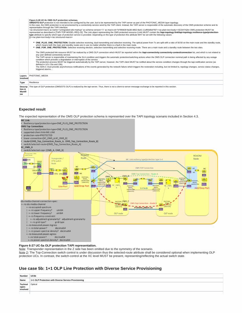
Figure 6-26 UC-5c OMS OLP protection schemas. protection is not intended to be configured by the user, but to be represented by the TAPI server as part of the PHOTONIC_MEDIA layer topology. OMS/OTS OLP
In this case, the OMS protection is not provisioned by a connectivity-service send by the TAPI client. Instead, the TAPI server is responsible of the automatic discovery of the OMS protection scheme and its representation through the TAPI interface. <ac:structured-macro ac:name="unmigrated-wiki-markup" ac:schema-version="1" ac:macro-id="b795563f-9a38-4852-8a41-11df50d5d793"><ac:plain-text-body><![CDATA[An OMS protection MUST be represented as described in [TAPI-TOP-MODEL-REQ-23]. The Link object representing the OMS protected resource (Link) MUST contain the /tapi-topology:link/tapi-topology:resilience-type/protection-
attribute to specify which type of protection service is provided. Depending on the type of protection this attribute MAY be set with the following values: type]]></ac:plain-text-body></ac:structured-macro>
ONE_PLUS_ONE_PROTECTION: Double selective receiving, dual transmitting and selective receiving. The optical power from Tx are split with a ratio of 50:50 on the main route and the standby route, which means both the main and standby routes are in use no matter whether there is a fault in the main route. ONE_FOR_ONE_PROTECTION: Selective receiving election, selective transmitting and selective receiving mode. There are a main route and a standby route between the two sites.
The OMS protected link resource MUST be realized by a OMS OLP connection which MUST be reported within the list, and which is not related to /tapi-connectivity:connectivity-context/connectionany user-defined connectivity-service. The TAPI server is responsible of maintaining the SLA condition and triggers the automatic protection/switching actions when the OMS OLP connection nominal path is being affected by any outage condition which provoke a degradation or interruption of the service. The protection process MUST be triggered automatically by the TAPI server, however, the TAPI client MUST be notified about the service condition changes through the tapi-notification service (as defined in UCs 15a and 15b). The SDN-C must provide asynchronous notifications of the events generated by the network failure which triggers the restoration including, but not limited to, topology changes, service status changes, triggered alarms…
Layers involved
PHOTONIC_MEDIA
Type Resilience
Description & Workflow
This type of OLP protection (OMS/OTS OLP) is realized by the tapi-server. Thus, there is not a client-to-server message exchange to be reported in this section.
Expected result
The expected representation of the OMS OLP protection schema is represented over the TAPI topology scenario included in Section 4.3.
Figure 6-27 UC-5a OLP protection TAPI representation.: Transponder representation in the Z side has been omitted due to the symmetry of the scenario.Note Note The Top-Connection switch control is under discussion thus the selected-route attribute shall be considered optional when implementing OLP 2:
protection UCs. In contrast, the switch-control at the XC level MUST be present, representing/reflecting the actual switch state.
Use case 5b: 1+1 OLP Line Protection with Diverse Service Provisioning
Number UC5b
Name 1+1 OLP Protection with Diverse Service Provisioning
Technologies involved
Optical

1. 2. 3.
Process/Areas Involved
Planning and Operations
Brief description
This use case covers the use of OLPs elements for 1+1 and 1:1 protection service at different layers OTSi/OTSiA. This use case does not allow intermediate regeneration in any of the MC trails, this capability is left for future use case specification.
Figure 6-28 UC-5b Line OLP protection schema.
protection represents a protection schema where an OLP is placed between the Transponder line ports and two add/drop ports of a ROADM. The OLP components duplicates the incoming Line Side OLPsignal and implements an Automatic Protection Switch (APS) which switch the traffic between the two Add/Drop ports upon loss of signal conditions (power measurement decrease under a target threshold) in less than 50ms. The TAPI server is responsible of maintaining the SLA condition and triggers the automatic protection/switching actions when the connectivity-service nominal path is being affected by any outage condition which provoke a degradation or interruption of the service. The protection process MUST be triggered automatically by the TAPI server, however, the TAPI client MUST be notified about the service condition changes through the tapi-notification service (as defined in UCs 15a and 15b). The SDN-C must provide asynchronous notifications of the events generated by the network failure which triggers the restoration including, but not limited to, topology changes, service status changes, triggered alarms.
Layers involved
PHOTONIC_MEDIA
Type Resilience
Description & Workflow
This type of OLP protection ( ) requires the reservation of two disjoint routes along the PHOTONIC_MEDIA layer for the provisioning of connections to support the 1+1 or 1:1 Connectivity Line Side OLPServices. The TAPI Client SHOULD select two valid SIPs, to be referenced by the CSEPs, which reference two PHOTONIC_LAYER_QUALIFER_OTSI NEPs directly connected to the Line-Side OLP elements, as described in the Connectivity Service example (Figure 6-30). The TAPI Client MAY include the three SIPs mapped to the MC/Photonic_Media NEPs representing the switching ports of the OLP components (MC1, MC2, MC3 as represented in the Figure), to associated to them different Protection Roles within the CSEPs definition (please note that zEnd peer SIPs, NEPs have been omitted in this explanation for simplicity). These protection roles MAY be in the example PROTECTED (71.D1 - MC1), WORK (72.D1 - MC2), PROTECT (73.D1 - MC3). Alternatively, the TAPI Client MAY delegate the protection role selection to the TAPI Server during the CS provisioning process and thus, only the two OTSi/Photonic_Media SIPs MUST be referenced within the CS request. In case, the protection role is delegated, the TAPI Client MUST include the attribute in the CS's request. preferred-restoration-layerThe Connectivity Service object sent to the TAPI Server MUST include the attribute to specify which type of protection tapi-connectivity:connectivity-service/tapi-topology:resilience-type/protection-typeservice is requested. Depending on the type of protection this attribute MAY be set with the following values:
ONE_PLUS_ONE_PROTECTION: Double selective receiving, dual transmitting and selective receiving. The optical power from Tx are split with a ratio of 50:50 on the main route and the standby route, which means both the main and standby routes are in use no matter whether there is a fault in the main route. ONE_FOR_ONE_PROTECTION: Selective receiving election, selective transmitting and selective receiving mode. There are a main route and a standby route between the two sites.
This UC is implemented following the same workflow described in "Description & Workflow" of UC1a described in section 6.2.1. : Resiliency workflow
Figure 6-29 UC-5b: Resiliency workflow.
Expected results
As described in UC1f (Section 6.2.6) the OLS PHOTONIC_MEDIA layer may be modelled unidirectionally or bidirectionally. In UC1f three possible models were presented:
Full-bidirectional - UNI and PHOTONIC_MEDIA model.Mixed-scenario - UNI bidirectional and topology unidirectional.Full-unidirectional OLS scenario - UNI and PHOTONIC_MEDIA unidirectional
For this use case, the mixed approach is not allowed. The other two models are described in the following subsections.

UC5b Example 1: Bidirectional OLP Line protection modelling
The expected result after the creation of the OLP protected PHOTONIC_LAYER_QUALIFER_OTSI connectivity service is represented over the TAPI topology scenario included in Figure 6-30.Please note, OTSiMC layer is intentionally left out from the diagram for simplicity but it MAY be included on top of every MC CEP described in the example.
Figure 6-30 UC-5b OLP TAPI Connectivity-Service low-level description.Once the CS is created, the TAPI Server is responsible of implementing the Switch control among the connections generated to support the different protection schemas (1+1, 1:1), which MUST provide automatic switch control between the working and protection connections in less than 50ms.The requested PHOTONIC_LAYER_QUALIFER_OTSI CS triggers the creation of:
Protected OTSi Top Connection.Protected MC Top Connection: which has two routes and implements switch-control and sub-switch-control based on its aEnd and zEnd lower-connections switch-control.
aEnd OLP site MC lower connection: implementing the switch-control between aEnd working and protection CEPs (MC-2, MC-3).N intermediate MC lower connections: without switch control (connections along the ROADM nodes)zEnd OLP site MC lower connection: implementing the switch-control between aEnd working and protection CEPs (respective CEPs to MC-2, MC-3 in the other zEnd OLP).
In case the service is 1:1 PROTECTION:
selected-connection-end-points: MC-1, MC-2 (and the respective CEPs in zEnd) switch between MC-2 and MC-3 when the conditions changes.selected-route: Route-A, and switch to Route-B, when the conditions changes. The Top-Connection switch control is under discussion thus the selected-route attribute shall be considered optional when implementing OLP protection UCs.
In case the service is 1+1 PROTECTION:
selected-connection-end-points: MC-1, MC-2 (and the respective CEPs in zEnd) initially when both routes are active, and switch between MC-2 and MC-3 when the conditions changes.selected-route: Route-A, Route-B initially when both routes are active, and switch to one of them, when the conditions changes. The Top-Connection switch control is under discussion thus the selected-route attribute shall be considered optional when implementing OLP protection UCs.
For both cases:
sub-switch-control: Referencing aEnd, zEnd OLP site MC lower connection switch-control objects.
UC5b Example 2: Unidirectional OLP Line protection modelling
In this case the connectivity model is split in the two directions (Add/Drop). Each direction includes a MC Top Connections which MUST be included within the related CS connection list.

The CS request in this case MUST include four CSEPs referencing the Add/Drop interfaces SIPs at aEnd and zEnd points. The actual guidelines for the switch control described for the bidirectional model applies to each unidirectional Top Connection. To all extend, the two
unidirectional Top Connections MUST expose the management of its switch-control the same one as it was described in the bidirectional model. Thus, the switch control at each direction is independent and but the bidirectional connectivity-service operational-state is impacted by the status of both.
Figure 6-31 UC-5b OLP TAPI Connectivity-Service low-level description. Unidirectional OLS modelling.
Required parameters
Table 35, Table 36, Table 37, Table 38 and Table 39 complements the information included in the Use Case 1a definition, with the Connectivity-Service, Connectivity-Service-End-Points, Connections and Switch-control, attributes required to implement this use case, this implies all attributes and objects included in Section 6.2.1.1 tables is required for this use case too.
Table 35: Connectivity-service attributes for 1+1 UC5b.
connectivity-service /tapi-common:context/tapi-connectivity:connectivity-context/connectivity-service
Attribute Allowed Values/Format Mod Sup Notes
resilience-type{" ": [ONE_FOR_ONE_PROTECTION, ONE_PLUS_ONE_PROTECTION]}protection-type
RW MProvided by tapi-client
preferred-restoration-layer[PHOTONIC_MEDIA]
RW MProvided by tapi-client
reversion-mode["REVERTIVE", "NON-REVERTIVE"]
RW MProvided by tapi-client
restore-priority"[0-9]+"
RW OProvided by tapi-client
hold-off-time"[0-9]{4}"
RW OProvided by tapi-client
wait-to-revert-time"[0-9]{4}"
RW OProvided by tapi-client
max-switch-times"[0-9]{2}"
RW OProvided by tapi-client
is-coordinated-switching-both-ends[true, false]
RW OProvided by tapi-client
is-lock-out RW OProvided by tapi-client

[true, false]
is-frozen[true, false]
RW OProvided by tapi-client
Table 36: Connectivity-service-End-Points attributes for UC5b.
connectivity-service-end-point /tapi-common:context/tapi-connectivity:connectivity-context/connectivity-service/end-point
Attribute Allowed Values/Format Mod Sup Notes
protection-role["WORK", "PROTECT", "PROTECTED"]
RW MProvided by tapi-client
Support only P2P
Table 37: Connection attributes for UC5b.
connection /tapi-common:context/tapi-connectivity:connectivity-context/connection
Attribute Allowed Values/Format Mod Sup Notes
switch-control List of { switch-control } RO MProvided by tapi-server
Table 38: Switch-control attributes for UC5b.
switch-control /tapi-common:context/tapi-connectivity:connectivity-context/connection/switch-control
Attribute Allowed Values/Format Mod Sup Notes
uuid "[0-9a-fA-F]{8} [0-9a-fA-F]{4} [0-9a-fA-F]{12}"[0-9a-fA-F]{4} [0-9a-fA-F]{4}
RO MAs per RFC 4122 Provided by tapi-server
name List of {value-name: value}
"value-name": "SWC_NAME" "value": " [0-9a-zA-Z]{64}"
RO MProvided by tapi-server
resilience-type
{" ": [ONE_PLUS_ONE_PROTECTION", protection-type"ONE_FOR_ONE_PROTECTION"]}
RO OProvided by tapi- server
reversion-mode ["REVERTIVE", "NON-REVERTIVE"]
RO OProvided by tapi- server
restore-priority "[0-9]+"
RO OProvided by tapi- server
hold-off-time "[0-9]{4}"
RO OProvided by tapi- server
wait-to-revert-time "[0-9]{4}"
RO OProvided by tapi- server
max-switch-times "[0-9]{2}"
RO OProvided by tapi- server
is-coordinated-switching-both-ends
[true, false]
RO OProvided by tapi- server
is-lock-out [true, false]
RO OProvided by tapi- server
is-frozen [true, false]
RO OProvided by tapi- server
preferred-restoration-layer List of ["PHOTONIC_MEDIA"]
RO MProvided by tapi- server
sub-switch-control List of {"/config/context/connection/{uuid}/switch-control/{switch_control_uuid}/"}
RO MProvided by tapi-server
switch List of { switch } RO MProvided by tapi-server

Table 39: Switch attributes for UC5b.
switch /tapi-common:context/tapi-connectivity:connectivity-context/connection/switch-control/switch
Attribute Allowed Values/Format Mod
Sup
Notes
local-id "[0-9a-zA-Z_]{32}"
RO MProvided by tapi-server
name List of {value-name: value}
"value-name": "SW_NAME" "value": " [0-9a-zA-Z_]{64}"
RO MProvided by tapi-server
switch-direction ["BIDIRECTIONAL", "INPUT", "OUTPUT"]
RO MProvided by tapi-server
selection-control ["LOCK_OUT", "NORMAL", "MANUAL", "FORCED"]
RO MProvided by tapi-server
selection-reason ["LOCKOUT", "NORMAL", "MANUAL", "FORCED", "WAIT_TO_REVERT", "SIGNAL_DEGRADE", "SIGNAL_FAIL"]
RO MProvided by tapi-server
selected-connection-end-point
List of {"connection-end-point-ref - /tapi-common:context/tapi-topology:topology-context/topology/node /owned-node-edge-point/tapi-connectivity:cep-list/connection-end-point/uuid "}
RO MProvided by tapi-server
selected-route List of {"/tapi-common:context/tapi-connectivity:connectivity-context/connection/{uuid}/route/{local_id}/ "} RO OProvided by tapi-server
Use case 5c: 1+1 protection with Diverse Service Provisioning (eSNCP)
Number UC5c
Name 1+1 protection with Diverse Service Provisioning (eSNCP)
Technologies involved
Optical
Process/Areas Involved
Planning and Operations
Brief description
This use case covers the provisioning of 1+1 protected services implemented through the electrical subnetwork connection protection (eSNCP) schema (Figure 6-32) also known as ODUk SNCP. ODUk SNCP protection protects services on line boards and on the units physically located behind the line boards. Cross-connections on the electrical layer are used to implement dual feeding and selective receiving, and protection switching is triggered by OTN overhead alarms. The cross-connection granularity is ODUk (k = 0, 1, 2, 3, 4, flex).
Figure 6-32 UC-5c eSNCP protection schema.
The actual implementation of the ODUk SNCP monitoring mode is out of the scope of this document but it is assumed that at least the Path Monitoring (PM) OTN mechanism MUST be supported to provide end-to-end ODU protection switching for DSR client services (e.g., multi-domain ODU services are out of the scope of this use case definition).
The TAPI server is responsible of maintaining the SLA condition and triggers the automatic protection/switching actions when the connectivity-service nominal path is being affected by any outage condition which provoke a degradation or interruption of the service. The protection process MUST be triggered automatically by the TAPI server, however, the TAPI client MUST be notified about the service condition changes through the tapi-
service (as defined in UCs 15a and 15b). notificationThe SDN-C must provide asynchronous notifications of the events generated by the network failure which triggers the restoration including, but not limited to, topology changes, service status changes, triggered alarms…
Layers involved
ODU

Type Resilience
Description & Workflow
The connectivity-service is requested between two DSR/ODU connectivity service endpoints and requires the reservation of two disjoint routes at the ODU layer between transponder's line interfaces. The TAPI Client SHOULD select two valid SIPs representing the client layer interfaces (which can be potentially at the DSR layer or at any LO-ODUj layer rate), to be referenced by the ConnectivityServiceEndPoints, which reference two NEPs which are intended to be connected by the 1+1 connectivity-service at the ODU layer (Figure 6-33). The TAPI Client MAY explicitly state the optical line interfaces to use to implement the protection at the HO-ODUk layer by including the two pairs of SIPs (67.D1, 68.D1) mapped to the OTSi NEPs representing the line ports of the transponders selected to provide the two disjoint routes for the HO-ODUk protected Top Connection. The TAPI Client MAY associate to them different Protection Roles within the CSEPs definition. Alternatively, the TAPI Client MAY delegate the protection role selection to the TAPI Server during the CS provisioning process and thus, only specify the two client SIPs (potentially at the DSR or any LO-ODUj layer rate) MUST be referenced within the CS request. In case, the protection role is delegated, the TAPI Client MUST include the preferred
attribute in the CS's request. -restoration-layerThe Connectivity Service object sent to the TAPI Server MUST include the attribute with tapi-connectivity:connectivity-service/tapi-topology:resilience-type/protection-type O
attribute value. NE_PLUS_ONE_PROTECTIONThis UC is implemented following the same workflow described in "Description & Workflow" of UC1a described in section 6.2.1
: Resiliency workflowThis UC is implemented following the same workflow described in "Description & Workflow" of UC5b described in section 6.5.2
Expected result
The expected result after the creation of the eSNCP ODU Connectivity Service is represented over the TAPI topology scenario included in Figure 6-33.
Figure 6-33 UC5c: eSNCP protection schema for HO-ODUk Top Connection.Once the CS is created, the TAPI Server is responsible of implementing the Switch control among the connections generated to support the ODU eSNCP protection schema, which MUST provide automatic switch control between the working and protection connections in less than 50ms. Please refer to the graphical illustration of this use case included Figure 6-33, which includes the Connection generated after the CS is created.The requested ODU CS triggers the creation of:
Protected DSR Top Connection.Protected HO-ODUk Top Connection: which has two routes and implements switch-control and sub-switch-control based on its aEnd and zEnd lower-connections switch-control.
aEnd HO-ODU lower connection: implementing the switch-control between aEnd protected CEP (HO-ODUk-1) and the working and protection CEPs (HO-ODUk-2, LO-ODU-3).zEnd HO-ODU lower connection: implementing the switch-control between zEnd protected CEP (HO-ODUk-4) and the working and protection CEPs (HO-ODUk-5, HO-ODUk-6).selected-connection-end-points: HO-ODUk-1 and HO-ODUk-2 or HO-ODUk-3 depending on the actual switch-control. The selected-CEPs switch between HO-ODUk-2 and HO-ODUk-3 when the network conditions changes in order to maintain the service SLA.selected-route: Route-A (HO-ODU-Top-Connection-A) or Route-B (HO-ODU-Top-Connection-B) according to the switching state of the lower XCs. The Top-Connection switch control is under discussion thus the selected-route attribute shall be considered optional when implementing OLP protection UCs.sub-switch-control: Referencing aEnd, zEnd lower-connection switch-control objects.
Additionally, the service might generate the PHOTONIC_MEDIA Layer connections if ODU layer does not has enough resources:
One working OTSi-Top Connection-A. Without switch control and its associated lower-connections.One protection OTSi -Top Connection-B. Without switch control and its associated lower-connections.One working MC Without switch control and its associated lower-connections.Top Connection-A.One protection MC Top Connection-B. Without switch control and its associated lower-connections.
Required parameters

Table 40 complements the information included in the Use Case 1a and Use Case 5b definitions, with the Connectivity-Service attributes required implementing this use case, this implies all attributes and objects included in Section 6.2.1.1 and 6.5.2.2 tables are required for this use case too.
Table 40: Connectivity-service attributes for UC5c.
connectivity-service /tapi-common:context/tapi-connectivity:connectivity-context/connectivity-service
Attribute Allowed Values/Format Mod Sup Notes
resilience-type {" ": ONE_PLUS_ONE_PROTECTION]}protection-type RW MProvided by tapi-client
preferred-restoration-layer[ODU]
RW MProvided by tapi-client
reversion-mode["REVERTIVE", "NON-REVERTIVE"]
RW MProvided by tapi-client
restore-priority"[0-9]+"
RW OProvided by tapi-client
hold-off-time"[0-9]{4}"
RW OProvided by tapi-client
wait-to-revert-time"[0-9]{4}"
RW OProvided by tapi-client
max-switch-times"[0-9]{2}"
RW OProvided by tapi-client
is-coordinated-switching-both-ends[true, false]
RW OProvided by tapi-client
is-lock-out[true, false]
RW OProvided by tapi-client
is-frozen[true, false]
RW OProvided by tapi-client
Use case 6a: Dynamic restoration policy for unconstrained and constrained connectivity services.
Number UC6a
Name Dynamic restoration policy for DSR/ODU/OTSI unconstrained connectivity services
Technologies involved
Optical
Process/Areas Involved
Planning and Operations
Brief description
This use case covers the provisioning of connectivity-services with restoration capabilities. The dynamic restoration capability can be requested at different layers i.e., DSR, ODU, OTSI. The TAPI client just need to specify two available Connectivity Service End Points and introduce the service characteristics (including the restoration-type and protection-type attributes). The TAPI server is responsible of maintaining the SLA condition and triggers the dynamic restoration process when the connectivity-service nominal path is being affected by any outage condition which provoke a degradation or interruption of the service. The TAPI server is expected to calculate the new restoration path according to the current network conditions when the SLA failure occurs. The dynamic restoration process MUST be triggered automatically by the TAPI server, however, the TAPI client MUST be notified about the service condition changes through
the tapi-notification service (as defined in UCs 15a and 15b).The SDN-C must provide asynchronous notifications of the events generated by the network failure which triggers the restoration including, but not limited to, topology changes,
service status changes, triggered alarms.Additional constrains, such coroute-inclusion or diversity-exclusion SHALL be account as at the time of the restoration occurs, i.e., applicable if possible.loose constrains
Layers involved
ODU, PHOTONIC_MEDIA
Type Resilience
Description & Workflow
The connectivity service is requested between two DSR/ODU/OTSI CSEPs. The TAPI Client SHOULD select two valid SIPs, to be referenced by the CSEPs, which reference two DSR/LO-ODUj/OTSI NEPs which are intended to be connected by the dynamic-restorable service. The TAPI Client MAY include the object to specify the preferred restoration layer, but the final decision on how to implement the tapi-connectivity:preferred-restoration-layerrestoration is responsibility of the TAPI server based on the current network conditions when the dynamic restoration process occurs. The Connectivity Service object sent to the TAPI Server MUST include the attribute tapi-connectivity:connectivity-service/tapi-topology:resilience-type/protection-typewith attribute value. DYNAMIC_RESTORATIONThis UC is implemented following the same workflow described in "Description & Workflow" of UC1a described in section 6.2.1.
: Resiliency workflow

Figure 6-34 UC-6a: Resiliency workflow.
Required parameters
Table 41 complements the information included in the Use Case 1a and Use Case 5b definitions, with the Connectivity-Service attributes required to implement this use case, this implies all attributes and objects included in Section 6.2.1.1 tables are required for this use case too.
Table 41: Connectivity-service attributes for UC6a.
connectivity-service /tapi-common:context/tapi-connectivity:connectivity-context/connectivity-service
Attribute Allowed Values/Format Mod Sup Notes
resilience-type {"
protection-type": [DYNAMIC_RESTORATION]}
RW MProvided by tapi-client
preferred-restoration-layer[ODU, PHOTONIC_MEDIA]
RW MProvided by tapi-client
reversion-mode["REVERTIVE", "NON-REVERTIVE"]
RW MProvided by tapi-client
restore-priority"[0-9]+"
RW OProvided by tapi-client
Use case 6b: Pre-Computed restoration policy for unconstrained and constrained connectivity services.
Number UC 6b
Name Pre-Computed restoration policy for unconstrained and constrained connectivity services.
Technologies involved
Optical
Process/Areas Involved
Planning and Operations
Brief description
This use case covers the provisioning of connectivity-services with restoration capabilities and the effective restoration process when a failure occurs in the nominal path. This use case assumes the same definition, workflow and specification defined in UC6a. Additionally, the SDN-C MUST accept a pre-computed (preset) restoration path as part of the connectivity-service provisioning request. Please note this use case depends on the use case 12b. The path computation operation might include routing policies (i.e., min. hops, min. latency) and/or constrains (the same applicable to the creation of services I .e., use cases 3). The underlying connection provisioning and management (including lower OCh/OTSi layer connections) is performed by the SDN-C. Also, the new path calculation in case of failure of the working path. The dynamic restoration process MUST be triggered automatically by the TAPI server, however, the TAPI client MUST be notified about the service condition changes through the service (as defined in UCs 15a and 15b). tapi-notificationThe SDN-C must provide asynchronous notifications of the events generated by the network failure which triggers the restoration including, but not limited to, topology changes, service status changes, triggered alarms.

1. 2.
Layers involved
ODU, PHOTONIC_MEDIA
Type Resilience
Description & Workflow
The initial path computation procedure is the same defined in UC12b. In particular, the two disjoined paths between the service-interface-points included in the Connectivity-Service request are previously computed by the SDN-C. This UC's connectivity-service provisioning and protection procedures follows the same workflow defined in the "Procedure" section of UC6a plus the following sub-workflow: The nominal and the pre-computed restoration paths MUST be included within the attribute. tapi-connectivity:connectivity-service/tapi-topology:include-pathDue to model limitations, the specification of the nominal and restoration route SHOULD be done sequentially.
First the tapi-client includes the nominal path in the Connectivity-Service initial POST request. Once the connectivity-service creation is completed, the tapi-client has to modify the existing Connectivity-Service object by adding the pre-computed restoration path, into the leaf-list attribute. The TAPI user MUST use the PUT operation to modify the existing object. tapi-connectivity:connectivity-service/tapi-topology:include-path
The Connectivity Service object sent to the SDN-C MUST include the tapi- attribute with connectivity:connectivity-service/tapi-topology:resilience-type/protection-typePRE_COMPUTED_RESTORATION attribute value.
: Resiliency workflowThe UC's protection workflow, of this UC, follows the same workflow defined in the "Procedure" section of UC6a.
Required parameters
Table 41 complements the information included in the Use Case 1a and Use Case 5b definitions, with the Connectivity-Service attributes required to implement this use case, this implies all attributes and objects included in Section 6.2.1.1 tables are required for this use case too.
Table 42: Connectivity-service attributes for UC6a.
connectivity-service /tapi-common:context/tapi-connectivity:connectivity-context/connectivity-service
Attribute Allowed Values/Format Mod Sup Notes
resilience-type {"
protection-type": [DYNAMIC_RESTORATION]}
RW MProvided by tapi-client
preferred-restoration-layer[ODU, PHOTONIC_MEDIA]
RW MProvided by tapi-client
reversion-mode["REVERTIVE", "NON-REVERTIVE"]
RW MProvided by tapi-client
restore-priority"[0-9]+"
RW OProvided by tapi-client
Use case 7a: Dynamic restoration and 1+1 protection of DSR/ODU unconstrained service provisioning.
Number UC7a
Name Restoration and protection 1+1
Technologies involved
Optical
Process/Areas Involved
Planning and Operations
Brief description
This use case covers the provisioning of connectivity-services with restoration capabilities and 1+1 protection capabilities. This first sub use case of this block proposes a 1+1 protection schema, which can be implemented either:
Over the PHOTONIC_MEDIA layer as the OLP Protection schema defined in section 6.5.2 Over the ODU layer as the eSNCP protection schema defined in section 6.5.3
This protection schema MUST provide automatic switch control between the working and protection connections in less than 50ms. Moreover, this use case introduces a second level of protection which is implemented through dynamic restoration of the first connection affected by a failure. The dynamic restoration policy MUST be implemented just one time. The Connectivity-Service can be requested at different layers i.e., DSR, ODU. The TAPI client just need to specify two available Connectivity Service End Points and introduce the service characteristics (including the restoration-type and protection-type attributes). The TAPI server is responsible of maintaining the SLA condition and triggers the protection and dynamic restoration processes when the connectivity-service working path is being affected by any outage condition which provoke a degradation or interruption of the service. The TAPI server is expected to calculate the new restoration path according to the current network conditions when the SLA failure occurs. The protection and dynamic restoration processes MUST be triggered automatically by the TAPI server, however, the TAPI client MUST be notified about the service condition changes through the tapi-notification service. The description of the notification process and its detail Low-Level-Design is out of the scope of this use case definition. Additional constrains, such coroute-inclusion or diversity-exclusion SHALL be account as at the time of the restoration occurs, i.e., applicable if possibleloose constrains
Layers involved
DSR, ODU, PHOTONIC_MEDIA
Type Resilience
Description & Workflow
The connectivity service is requested between two DSR/ODU CSEPs. The TAPI Client SHOULD select two valid SIPs, to be referenced by the CSEPs, which reference two DSR/LO-ODUj NEPs which are intended to be connected by the dynamic-restorable service. The TAPI Client MAY include the object to specify the preferred restoration layer, but the final decision on how to implement the tapi-connectivity:preferred-restoration-layerrestoration is responsibility of the TAPI server based on the current network conditions when the dynamic restoration process occurs.

1. 2.
The Connectivity Service object sent to the TAPI Server MUST include the attribute with tapi-connectivity:connectivity-service/tapi-topology:resilience-type/protection-type attribute value. ONE_PLUS_ONE_PROTECTION_WITH_DYNAMIC_RESTORATION
This UC is implemented following the same workflow described in "Description & Workflow" of UC1a described in section 6.2.1 : Resiliency workflow
The service with this SLA MUST be able to support a first failure within the nominal or protection paths and switched within 50ms. After the first failure, the affected path is dynamically restored by the control plane, by calculating a new path which may imply a wavelength change.
The first failure affecting the nominal path MUST trigger the protection workflow described in "Description & Workflow" of UC5b described in section 6.5.2 The restoration of the affected route by the first failure MUST trigger the protection workflow described in "Description & Workflow" of UC6a described in section 6.5.4
Required parameters
Table 43 complements the information included in the Use Case 1 and Use Case 5b definitions, with the Connectivity-Service, Connectivity-Service-End-Points, Connections and Switch-control, attributes required to implement this use case, this implies all attributes and objects included in Section 6.2.1.1 and 6.5.2.2 tables are required for this use case too.
Table 43: Connectivity-service attributes for UC7a.
connectivity-service /tapi-common:context/tapi-connectivity:connectivity-context/connectivity-service
Attribute Allowed Values/Format Mod Sup Notes
resilience-type
{" ": [protection-type
ONE_PLUS_ONE_PROTECTION_WITH_DYNAMIC_RESTORATION ]}
RW MProvided by tapi-client
preferred-restoration-layer[ODU, PHOTONIC_MEDIA]
RW MProvided by tapi-client
reversion-mode["REVERTIVE", "NON-REVERTIVE"]
RW MProvided by tapi-client
restore-priority"[0-9]+"
RW OProvided by tapi-client
hold-off-time"[0-9]{4}"
RW OProvided by tapi-client
wait-to-revert-time"[0-9]{4}"
RW OProvided by tapi-client
max-switch-times"[0-9]{2}"
RW OProvided by tapi-client
is-coordinated-switching-both-ends [true, false]
RW OProvided by tapi-client
is-lock-out[true, false]
RW OProvided by tapi-client
is-frozen[true, false]
RW OProvided by tapi-client
Use case 7b: Pre-Computed restoration policy and 1+1 protection of DSR/ODU unconstrained service provisioning.
Number UC7b
Name Pre-Computed restoration policy and 1+1 protection of DSR/ODU unconstrained service provisioning.
Technologies involved
Optical
Process/Areas Involved
Planning and Operations
Brief description
This use case covers the provisioning of connectivity-services with restoration capabilities and 1+1 protection capabilities and the demonstration of the effective protection and restoration process when a failure occurs in the nominal path. This use case of this block proposes a 1+1 protection schema, which can be implemented either:
At the OTSi_PHOTONIC_MEDIA layer, as the OLP Protection schema defined in UC5b. Or at the ODU layer, as the eSNCP protection schema defined in UC5c.
Additionally, the SDN-C MUST accept a pre-computed (preset) restoration path as part of the connectivity-service provisioning request. Please note this use case depends on the use case 12a. The path computation operation might include routing policies (i.e., min. hops, min. latency) and/or constrains (the same applicable to the creation of services i.e., use cases 3).
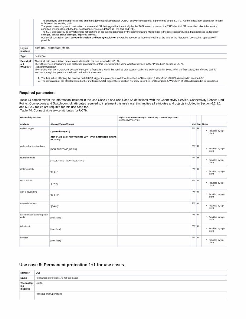
1. 2.
The underlying connection provisioning and management (including lower OCh/OTSi layer connections) is performed by the SDN-C. Also the new path calculation in case of failure of the working path The protection and dynamic restoration processes MUST be triggered automatically by the TAPI server, however, the TAPI client MUST be notified about the service condition changes through the tapi-notification service (as defined in UCs 15a and 15b). The SDN-C must provide asynchronous notifications of the events generated by the network failure which triggers the restoration including, but not limited to, topology changes, service status changes, triggered alarms… Additional constrains, such or SHALL be account as loose constrains at the time of the restoration occurs, i.e., applicable if coroute-inclusion diversity-exclusionpossible.
Layers involved
DSR, ODU, PHOTONIC_MEDIA
Type Resilience
Description & Workflow
The initial path computation procedure is identical to the one included in UC12b. The UC's service provisioning and protection procedures, of this UC, follows the same workflow defined in the "Procedure" section of UC7a.
: Resiliency workflowThe service with this SLA MUST be able to support a first failure within the nominal or protection paths and switched within 50ms. After the first failure, the affected path is
restored through the pre-computed path defined in the service.
The first failure affecting the nominal path MUST trigger the protection workflow described in "Description & Workflow" of UC5b described in section 6.5.1. The restoration of the affected route by the first failure MUST trigger the protection workflow described in "Description & Workflow" of UC6a described in section 6.5.4
Required parameters
Table 44 complements the information included in the Use Case 1a and Use Case 5b definitions, with the Connectivity-Service, Connectivity-Service-End-Points, Connections and Switch-control, attributes required to implement this use case, this implies all attributes and objects included in Section 6.2.1.1 and 6.5.2.2 tables are required for this use case too.
Table 44: Connectivity-service attributes for UC7b.
connectivity-service /tapi-common:context/tapi-connectivity:connectivity-context/connectivity-service
Attribute Allowed Values/Format Mod Sup Notes
resilience-type
{" ": [protection-type
ONE_PLUS_ONE_PROTECTION_WITH_PRE_COMPUTED_RESTO ]}RATION
RW MProvided by tapi-client
preferred-restoration-layer[ODU, PHOTONIC_MEDIA]
RW MProvided by tapi-client
reversion-mode["REVERTIVE", "NON-REVERTIVE"]
RW MProvided by tapi-client
restore-priority"[0-9]+"
RW OProvided by tapi-client
hold-off-time"[0-9]{4}"
RW OProvided by tapi-client
wait-to-revert-time"[0-9]{4}"
RW OProvided by tapi-client
max-switch-times"[0-9]{2}"
RW OProvided by tapi-client
is-coordinated-switching-both-ends [true, false]
RW OProvided by tapi-client
is-lock-out[true, false]
RW OProvided by tapi-client
is-frozen[true, false]
RW OProvided by tapi-client
Use case 8: Permanent protection 1+1 for use cases
Number UC8
Name Permanent protection 1+1 for use cases
Technologies involved
Optical
Planning and Operations

Process/Areas Involved
Brief description
This use case covers the provisioning of connectivity-services with permanent 1+1 protection capabilities and the demonstration of the effective protection and restoration process when a failure occurs in the nominal or backup paths.
This use case of this block proposes a 1+1 protection schema, which can be implemented either:
At the OTSi_PHOTONIC_MEDIA layer, as the OLP Protection schema defined in UC5b At the ODU layer, as the eSNCP protection schema defined in UC5c
The underlying connection provisioning and management (including lower OCh/OTSi layer connections) is performed by the SDN-C. Also, the new path calculation in case of failure of the working path MUST be computed and provisioned by the SDN-C according to the control-plane policies installed in the network.
The TAPI server is responsible of maintaining the SLA condition and triggers the automatic protection/switching actions when the connectivity-service nominal path is being affected by any outage condition which provoke a degradation or interruption of the service. The protection process MUST be triggered automatically by the TAPI server, however, the TAPI client MUST be notified about the service condition changes through the tapi-notification service (as defined in UCs 15a and 15b). The SDN-C must provide asynchronous notifications of the events generated by the network failure which triggers the restoration including, but not limited to, topology changes, service status changes, triggered alarms…
Layers involved
DSR, ODU, PHOTONIC_MEDIA
Type Resilience
Description & Workflow
The UC's service provisioning procedure of this UC follows the same workflow defined in the "Procedure" section of UC5c. Additional considerations:
The Connectivity Service object sent to the SDN-C MUST include the tapi-connectivity:connectivity-service/tapi-topology:resilience-type/protection-type attribute with PERMANENT_ONE_PLUS_ONE_PROTECTION attribute value.
Resiliency workflow: The service implementing protection schema MUST be able to switch from the nominal path to the backup path against any PERMANENT_ONE_PLUS_ONE_PROTECTION
failure which degrades the service under the defined SLA conditions within 50ms.There are 2 possible fails:
If the working path fails, the control plane will commute to the protection path. The role of this path changes from protected to working and the control plane will compute and provision a new protection path. This procedure will occur permanently. The protection workflow described in "Description & Workflow" of UC5b described in section 6.5.1. If the protection path fails, the control plane will compute and restore it through a new protection path. This procedure will be permanent as the previous one and it MUST trigger the same workflow described in "Description & Workflow" of UC6a described in section 6.5.4.
Required parameters
The following table complements the information included in the Use Case 1a and Use Case 5b definitions, with the Connectivity-Service, Connectivity-Service-End-Points, Connections and Switch-control, attributes required to implement this use case, this implies all attributes and objects included in Section 6.2.1.1 and 6.5.2.2 tables are required for this use case too.
Table 45: Connectivity-service attributes for UC8.
connectivity-service /tapi-common:context/tapi-connectivity:connectivity-context/connectivity-service
Attribute Allowed Values/Format Mod Sup Notes
resilience-type{"protection-type": [
PERMANENT_ONE_PLUS_ONE_PROTECTION ]}
RW MProvided by tapi-client
preferred-restoration-layer[ODU, PHOTONIC_MEDIA]
RW MProvided by tapi-client
reversion-mode["REVERTIVE", "NON-REVERTIVE"]
RW MProvided by tapi-client
restore-priority"[0-9]+"
RW OProvided by tapi-client
hold-off-time"[0-9]{4}"
RW OProvided by tapi-client
wait-to-revert-time"[0-9]{4}"
RW OProvided by tapi-client
max-switch-times"[0-9]{2}"
RW OProvided by tapi-client
is-coordinated-switching-both-ends [true, false]
RW OProvided by tapi-client
is-lock-out[true, false]
RW OProvided by tapi-client
is-frozen[true, false]
RW OProvided by tapi-client

Maintenance
Use Case 10: Service deletion (applicable to all previous use cases)
Number UC10
Name Service deletion (applicable to all previous use cases)
Technologies involved
Optical
Process/Areas Involved
Planning and Operations
Brief description
This use case covers the deletion of a target connectivity-service and all the related connections created by this service (i.e., all connections included as part of the CS connection list). If the user is not authorized to delete the target resource, then an error response containing a "403 Forbidden" status-line SHOULD be returned. The error-tag value "access-denied" is returned in this case. A server MAY return a "404 Not Found" status-line, as described in . The error-Section 6.5.4 in [RFC7231]tag value "invalid-value" is returned in this case.
Layers involved
DSR, ODU, PHOTONIC_MEDIA
Type Resilience
Description & Workflow
The TAPI client MUST specify the attribute in the RESTCONF DELETE request to identify the service to be tapi-connectivity:connectivity-service/uuidremoved.
Figure 6-35 UC-10: Service Deletion workflow.
Planning
Use case 12a: Pre-calculation of the optimum path (applicable to all previous use cases)
Number UC12a
Name Pre-calculation of the optimum path (applicable to all previous use cases)
Technologies involved Optical
Process/Areas Involved Planning and Operations
<ac:structured-macro ac:name="unmigrated-wiki-markup" ac:schema-version="1" ac:macro-id="0bc768e9-c4ab-44a7-bb98-518f9fb1fbfb"><ac:plain-text-body><![CDATA[
Brief description [Disclaimer]: This use case isn

ot completely discussed,nor agreed by the TAPI team. This use case remains documented for future discussion and th

e content of it may vary infuture versions.Thus,the use of the documentation for this use case should be considered

only for Proof of Concept purposes.
]]></ac:plain-text-body></ac:structured-macro>
The SDN-Cmustsupport the pre-calculation

ofa service path between two endpoints (site/interface)ofthe network including the network layer(i.e., DSR, ODU, OTSi/OTSiA, MC). The und

erlying calculation ofthe newpath ismade by the SDN-C, and it mightinclude regeneration (3R). The path computation operation mightinclude rout

ing policies (i.e., min. hops,min. latency)and/or constrains (the same applicable tothe creation ofservices i.e., use cases 3). If notspecific

layerisincluded within the request, the calculated path MUST include all routed links even if they belong tomultiple layers.
Layers involved DSR, ODU, PHOTONIC_MEDIA
Type Planning
Description & Workflow

Figure 6-36 UC-12a: Pre-calculation of the optimum path workflow.
Required parameters
Table 46: Path-computation-context attributes.
path-computation-context
Attribute Allowed Values/Format Mod Sup Notes
path-comp-service List of {path-comp-service} RW MProvided by tapi-client
path List of {path} RO MProvided by tapi-server
Table 47: Path-comp-serv object's attributes.
path-comp-serv
Attribute Allowed Values/Format Mod Sup Notes
end-point List of {path-service-end-point} RW MProvided by tapi-client
routing-constraint { routing-constraint } RW MProvided by tapi-client
topology-constraint { topology-constraint } RW MProvided by tapi-client
objective-function {objective-function} RW MProvided by tapi-client *
optimization-constraint {optimization-constraint}
uuid"[0-9a-fA-F]{8} [0-9a-fA-F]{4} [0-9a-fA-F]{12}"[0-9a-fA-F]{4} [0-9a-fA-F]{4}
RW MAs per RFC 4122 Provided by tapi-client
name List of {value-name: value}
"value-name": "PATH_COMP_REQ_NAME" "value": " [0-9a-zA-Z_]{64}"
RW MProvided by tapi-client
Table 48: Path-service endpoint object's attributes.
path-service-end-point

Attribute Allowed Values/Format Mod
Sup
Notes
local-id"[0-9a-zA-Z_]{32}"
RW MProvided by tapi-client
layer-protocol-name List of ["DSR", "ODU", "PHOTONIC_MEDIA"]
RW MProvided by tapi-client
layer-protocol-qualifier List of ["DIGITAL_SIGNAL_TYPE", "ODU_TYPE",
"PHOTONIC_LAYER_QUALIFIER"]
RW MProvided by tapi-server All children identities defined for ["DIGITAL_SIGNAL_TYPE", "ODU_TYPE", "PHOTONIC_LAYER_QUALIFIER"] MUST be supported.
administrative-state ["UNLOCKED", "LOCKED"]
RW OProvided by tapi-client
operational-state ["ENABLED", "DISABLED"]
RO OProvided by tapi-server
lifecycle-state["PLANNED", "POTENTIAL_AVAILABLE", "POTENTIAL_BUSY", "INSTALLED", "PENDING_REMOVAL"]
RO OProvided by tapi-server
direction["BIDIRECTIONAL", "INPUT", "OUTPUT"]
RW OProvided by tapi-client
role["SYMMETRIC", "TRUNK"]
RW OProvided by tapi-client Support only P2P
capacity "total-size": {value: unit}
"value": "[0-9]{8}",
"unit": ["TB", "TBPS", "GB", "GBPS", "MB", "MBPS", "KB", "KBPS"]
RW OProvided by tapi-client
service-interface-point
"/tapi-common:context/service-interface-point/uuid" RW MProvided by tapi-client
Table 49: Topology constraint object's attributes.
topology-constraint
Attribute Allowed Values/Format Mod Sup Notes
include-topology LeafList of {
"[0-9a-fA-F]{8} [0-9a-fA-F]{4} [0-[0-9a-fA-F]{4} [0-9a-fA-F]{4}9a-fA-F]{12}"
}
RW OThis is a loose constraint - that is it is unordered and could be a partial list
avoid-topology LeafList of {
"[0-9a-fA-F]{8} [0-9a-fA-F]{4} [0-[0-9a-fA-F]{4} [0-9a-fA-F]{4}9a-fA-F]{12}"
}
RW OThis is a loose constraint - that is it is unordered and could be a partial list
include-path LeafList of {
"[0-9a-fA-F]{8} [0-9a-fA-F]{4} [0-[0-9a-fA-F]{4} [0-9a-fA-F]{4}9a-fA-F]{12}"
}
RW MProvided by tapi-client This is a loose constraint - that is it is unordered and could be a partial list. The uuid MUST refer to a valid { tapi-path-computation:path} object present within the tapi-server datastore.
exclude-path LeafList of {
"[0-9a-fA-F]{8} [0-9a-fA-F]{4} [0-[0-9a-fA-F]{4} [0-9a-fA-F]{4}9a-fA-F]{12}"
}
RW MProvided by tapi-client This is a loose constraint - that is it is unordered and could be a partial list. The uuid MUST refer to a valid {tapi-path-computation:path} object present within the tapi-server datastore
include-node LeafList of {
"[0-9a-fA-F]{8} [0-9a-fA-F]{4} [0-[0-9a-fA-F]{4} [0-9a-fA-F]{4}9a-fA-F]{12}"
RW MProvided by tapi-client This is a loose constraint - that is it is unordered and could be a partial list. The uuid MUST refer to a valid {tapi-topology:node} object present within the tapi-server datastore

}
exclude-node LeafList of {
"[0-9a-fA-F]{8} [0-9a-fA-F]{4} [0-[0-9a-fA-F]{4} [0-9a-fA-F]{4}9a-fA-F]{12}"
}
RW MProvided by tapi-client Reference to an existing node-id already present in the TAPI server context MUST be valid. The uuid MUST refer to a valid {tapi-topology:node} object present within the tapi-server datastore
include-link LeafList of {
"[0-9a-fA-F]{8} [0-9a-fA-F]{4} [0-[0-9a-fA-F]{4} [0-9a-fA-F]{4}9a-fA-F]{12}"
}
RW MProvided by tapi-client This is a loose constraint - that is it is unordered and could be a partial list The uuid MUST refer to a valid {tapi-topology:link} object present within the tapi-server datastore
exclude-link LeafList of {
"[0-9a-fA-F]{8} [0-9a-fA-F]{4} [0-[0-9a-fA-F]{4} [0-9a-fA-F]{4}9a-fA-F]{12}"
}
RW MProvided by tapi-client This is a loose constraint - that is it is unordered and could be a partial list The uuid MUST refer to a valid {tapi-topology:link} object present within the tapi-server datastore
preferred-transport-layer [ODU, PHOTONIC_MEDIA]
RW MProvided by tapi-client
Table 50: Routing constraint object's attributes.
routing-constraint
Attribute Allowed Values/Format Mod
Sup
Notes
cost-characteristic
{ cost-name, cost-value, cost-algorithm}
"cost-name": "string", "cost-value": "string", "cost-algorithm": "string",
RW MProvided by tapi-client
latency-characteristic
{ traffic-property-name, fixed-latency-characteristic, queing-latency-characteristic, jitter-characteristic, wander-characteristic }
"traffic-property-name": "string", "fixed-latency-characteristic": "string", "queing-latency-characteristic": "string", "jitter-characteristic":"string" "wander-characteristic":"string"
RW MProvided by tapi-client
risk-diversity-characteristic
{ risk-characteristic-name, risk-identifier-list}
risk-characteristic-name risk-identifier-list
RW MProvided by tapi-client
diversity-policy
{SRLG, SRNG, SNG,NODE, LINK} RW MProvided by tapi-client
route-objective-function
["MIN_WORK_ROUTE_HOP", "MIN_WORK_ROUTE_COST", "MIN_WORK_ROUTE_LATENCY", "MIN_SUM_OF_WORK_AND_PROTECTION_ROUTE_HOP", "MIN_SUM_OF_WORK_AND_PROTECTION_ROUTE_COST", "MIN_SUM_OF_WORK_A ND_PROTECTION_ROUTE_LATENCY", "LOAD_BALANCE_MAX_UNUSED_CAPACITY"
RW MProvided

by tapi-client
route-direction ["BIDIRECTIONAL", "INPUT", "OUTPUT"]
RW MProvided by tapi-client
is-exclusive
Boolean RW MProvided by tapi-client
Table 51: Objective function object's attributes.
objective-function
Attribute Allowed Values/Format Mod Sup Notes
bandwidth-optimization {"MINIMIZE", "MAXIMIZE", "ALLOW", "DISALLOW", "DONT_CARE"] RW MProvided by tapi-client
concurrent-paths {"MINIMIZE", "MAXIMIZE", "ALLOW", "DISALLOW", "DONT_CARE"] RW MProvided by tapi-client
cost-optimization {"MINIMIZE", "MAXIMIZE", "ALLOW", "DISALLOW", "DONT_CARE"] RW MProvided by tapi-client
link-utilization {"MINIMIZE", "MAXIMIZE", "ALLOW", "DISALLOW", "DONT_CARE"] RW MProvided by tapi-client
resource-sharing {"MINIMIZE", "MAXIMIZE", "ALLOW", "DISALLOW", "DONT_CARE"] RW MProvided by tapi-client
local-id"[0-9a-zA-Z_]{32}"
RW MProvided by tapi-client
name List of {value-name: value}
"value-name": "OBJ_FUNCTION" "value": " [0-9a-zA-Z_]{64}"
RW OProvided by tapi-client
Table 52: Optimization-constraint object's attributes.
optimization-constraint
Attribute Allowed Values/Format Mod
Sup
Notes
traffic-interruption
{ "MINIMIZE", "MAXIMIZE", "ALLOW", "DISALLOW", "DONT_CARE"] RW MProvided by tapi-client
local-id"[0-9a-zA-Z_]{32}"
RW MProvided by tapi-client
name List of {value-name: value}
"value-name": "OPT_CONSTRAINT_NAME" <ac:structured-macro ac:name="unmigrated-wiki-markup" ac:schema-version="1" ac:macro-id="8a04bb42-35d0-4db7-b2b2-ecdf5f9545d3"><ac:plain-text-body><![CDATA[* "value": " [0-9a-zA-Z_]{64}"
RW OProvided by tapi-client
]]></ac:plain-text-body></ac:structured-macro>

Use case 12b: Simultaneous pre-calculation of two disjoint paths
Number UC12b
Name Simultaneous pre-calculation of two disjoint paths
Technologies involved Optical
Process/Areas Involved Planning and Operations
<ac:structured-macro ac:name="unmigrated-wiki-markup" ac:schema-version="1" ac:macro-id="d7811740-6c02-4979-804b-290cef32c528"><ac:plain-text-body><![CDATA[
Brief description [Disclaimer]: This use case isnot completely discussed,nor agreed by the TAPI team. This use case r

emains documented for future discussion and the content of it may vary infuture versions.Thus,the use of the docu

mentation for this use case should be considered only for Proof of Concept purposes.
]]></ac:plain-text-body></ac:stru

ctured-macro>
The SDN-Cmustsupport the pre-calculation ofa service path between two endpoints (site/interface)ofthe network including the

network layer(i.e., DSR, ODU, OCh/OTSi, MC). The underlying calculation ofthe newpath ismade by the SDN-C, and it mightinclude regener

ation (3R). The path computation operation mightinclude routing policies (i.e., min. hops,min. latency)and/or constrains (the same applicable to

the creation ofservices i.e., use cases 3). If notspecific layerisincluded within the request, the calculated path MUST include all routed link

s even if they belong tomultiple layers.
Layers involved DSR, ODU, PHOTONIC_MEDIA
Type Planning
Description & Workflow The simulateneous calculation is not yet ready in the standard NBI at the moment, thus a secuential approach will be followed. The approach is to request two paths sequentially and impose a "exclude-path" constrain to the second path-request by including a reference to the previously calculated, thus assuring the second path is disjoint from the previous one.

Figure 6-37 UC-12b: Simultaneous pre-calculation of two disjoint paths
Notifications and alarms.
Use case 13a: Subscription to notification service.
Number
UC 13a
Name Subscription to notification service.
Technologies involved
All
Process/AreasInvolved
Planning and Operations
Brief description
The SDN-C MUST offer a notification subscription service which allows several client applications to subscribe to asynchronous notifications about the changes occurred in the network. The notification stream service SHALL allow notification filtering to select the relevant information upon the use case to be implemented. The filtering system MUST allow filtering by object-type (i.e., Connectivity-Service, Connection…), by networking layer, by notification-type (OBJECT_CREATION, ATTRIBUTE_VALUE_CHANGE, OBJECT_DELETION, ALARM_EVENT, THRESHOLD_CROSSING_ALERT). The same client application MAY request more than one notification stream with different filtering characteristics. All NOTIFICATIONs emitted by the SDN-C through a dedicated subscribtion channel must be correlated linearly by: /tapi-common:context/tapi-notification:notification-context/tapi-notification:notification:

+--ro sequence-number? uint64
And timely by: /tapi-common:context/tapi-notification:notification-context/tapi-notification:notification: +--ro event-time-stamp? tapi-common:date-and-time
The TAPI server MUST support the RESTCONF Notifications subscription mechanism is defined in . In addition the TAPI server must support the Query Parameter, as defined in Section 6.3 of [RFC 8040] "filter", to indicate the target subset of the possible events being advertised by the RESTCONF server stream. Section 4.8.4 of [RFC 8040]
<ac:structured-macro ac:name="unmigrated-wiki-markup" ac:schema-version="1" ac:macro-id="fd49a312-6499-47b1-a564-beaaef511a13"><ac:plain-text-body><![CDATA[The TAPI server MUST implement the defined filtering mechanism following the [XPath] format. Here we define some possible filters that can be designed by the and which MUST be accepted by the server. tapi-client Please note the scope of the
Thus, please considers the following examples as further documentation to help the development teams to understand the defined service. filtering mechanism is not restricted to the examples proposed.]]></ac:plain-text-body></ac:structured-macro>Without loss of generality, for the examples please assume all notifications are defined within the custom " " stream. tapi-notificationExample 1: ---------------------------------------------------------- // filter = /tapi-notification:notification/notification-type='OBJECT_CREATION'
GET /streams/tapi-notification?filter=%2Ftapi-notification%3Anotification%2Fnotification-type%3D'OBJECT_CREATION'
Example 2: ---------------------------------------------------------- // filter = (/tapi-notification:notification/notification-type='ATTRIBUTE_VALUE_CHANGE' and /tapi-notification:notification/target-object-type='NODE')
GET /streams/tapi-notification?filter=%2Ftapi-notification%3Anotification%2Fnotification-type%3D'ATTRIBUTE_VALUE_CHANGE'%20and%20%2Ftarget-object-type%3D'NODE'
Example 3: ---------------------------------------------------------- <ac:structured-macro ac:name="unmigrated-wiki-markup" ac:schema-version="1" ac:macro-id="26b667bc-2176-4137-8b09-681ed90256b0"><ac:plain-text-body><![CDATA[// filter = /tapi-notification:notification/target-object-name['INVENTORY_ID']/value[contains(.,'/ne=MadridNorte')] ]]></ac:plain-text-body></ac:structured-macro> <ac:structured-macro ac:name="unmigrated-wiki-markup" ac:schema-version="1" ac:macro-id="998f6a20-b3ef-4633-a429-4497e9fcac82"><ac:plain-text-body><![CDATA[ GET /streams/tapi-notification?filter=%2Ftapi-notification%3Anotification%2Ftarget-object-name['INVENTORY_ID']%2Fvalue[contains(.%2C'/ne=MadridNorte')] ]]></ac:plain-text-body></ac:structured-macro>
Layersinvolved
DSR, ODU, PHOTONIC_MEDIA
Type Notifications and Alarms
Description & Workflow
Figure 6-38 UC-13a: Subscription to notification stream service
Please assume RESTCONF Event Notifications MUST be supported by the SDN-C, while the TAPI Notification subscription mechanism is optional. The asyncronous notification transport protocol MUST be SSE ( http://www.w3.org/TR/2015/REC-eventsource-20150203/).
Use case 14a: Notification of new topology element (topology, link, node, node-edge-point) inserted/removed in/from the network
Number UC 14a
Name Notification of new topology element (topology, link, node, node-edge-point) inserted/removed in/from the network
Technologies involved All
Process/Areas Involved Planning and Operations
Brief description The SDN-C Notification system MUST emit events exposing the creation/deletion of Topology object-types such topology, link, node and node-edge-points. The SDN-C MUST report a TOPOLOGY object creation/deletion notification when a network element is introduced or removed from the network or a logical construct is generated as part of a connection or service is provisioned in the network. A SDN-C NBI client which is subscribed to the notification service with the filter which includes the following parameters:
notification-type= OBJECT_CREATION, OBJECT_DELETION object-type= TOPOLOGY, NODE, LINK or NODE_EDGE_POINT
, it must receive all notification which are address by the filter with the corresponding object and notification types and identifiers: /tapi-common:context/tapi-notification:notification-context/tapi-notification:notification:
+--ro notification-type? notification-type
+--ro target-object-type? tapi-common:object-type
+--ro target-object-identifier? tapi-common:uuid
<ac:structured-macro ac:name="unmigrated-wiki-markup" ac:schema-version="1" ac:macro-id="9bcd1088-8c58-42ac-bc22-ba21edd1a4cb"><ac:plain-text-body><![CDATA[ +--ro target-object-name* [value-name] ]]></ac:plain-text-body></ac:structured-macro>
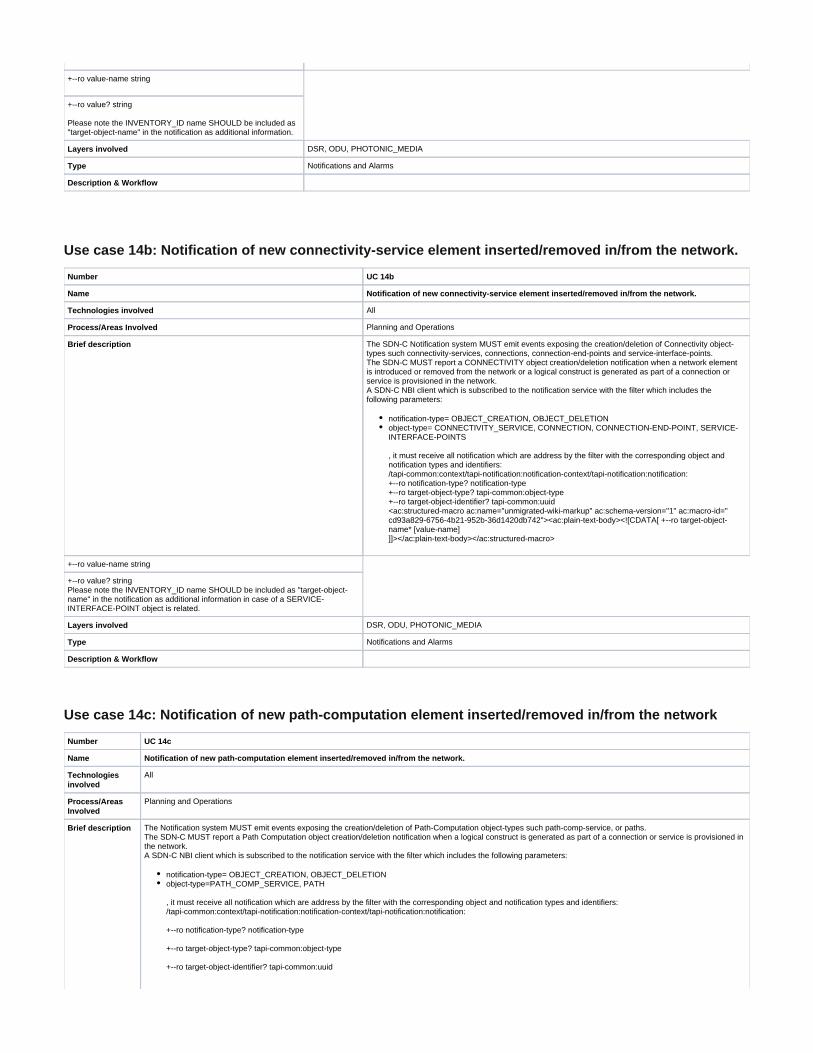
+--ro value-name string
+--ro value? string
Please note the INVENTORY_ID name SHOULD be included as "target-object-name" in the notification as additional information.
Layers involved DSR, ODU, PHOTONIC_MEDIA
Type Notifications and Alarms
Description & Workflow
Use case 14b: Notification of new connectivity-service element inserted/removed in/from the network.
Number UC 14b
Name Notification of new connectivity-service element inserted/removed in/from the network.
Technologies involved All
Process/Areas Involved Planning and Operations
Brief description The SDN-C Notification system MUST emit events exposing the creation/deletion of Connectivity object-types such connectivity-services, connections, connection-end-points and service-interface-points. The SDN-C MUST report a CONNECTIVITY object creation/deletion notification when a network element is introduced or removed from the network or a logical construct is generated as part of a connection or service is provisioned in the network. A SDN-C NBI client which is subscribed to the notification service with the filter which includes the following parameters:
notification-type= OBJECT_CREATION, OBJECT_DELETION object-type= CONNECTIVITY_SERVICE, CONNECTION, CONNECTION-END-POINT, SERVICE-INTERFACE-POINTS
, it must receive all notification which are address by the filter with the corresponding object and notification types and identifiers: /tapi-common:context/tapi-notification:notification-context/tapi-notification:notification: +--ro notification-type? notification-type +--ro target-object-type? tapi-common:object-type +--ro target-object-identifier? tapi-common:uuid <ac:structured-macro ac:name="unmigrated-wiki-markup" ac:schema-version="1" ac:macro-id="cd93a829-6756-4b21-952b-36d1420db742"><ac:plain-text-body><![CDATA[ +--ro target-object-name* [value-name] ]]></ac:plain-text-body></ac:structured-macro>
+--ro value-name string
+--ro value? string Please note the INVENTORY_ID name SHOULD be included as "target-object-name" in the notification as additional information in case of a SERVICE-INTERFACE-POINT object is related.
Layers involved DSR, ODU, PHOTONIC_MEDIA
Type Notifications and Alarms
Description & Workflow
Use case 14c: Notification of new path-computation element inserted/removed in/from the network
Number UC 14c
Name Notification of new path-computation element inserted/removed in/from the network.
Technologies involved
All
Process/Areas Involved
Planning and Operations
Brief description The Notification system MUST emit events exposing the creation/deletion of Path-Computation object-types such path-comp-service, or paths. The SDN-C MUST report a Path Computation object creation/deletion notification when a logical construct is generated as part of a connection or service is provisioned in the network. A SDN-C NBI client which is subscribed to the notification service with the filter which includes the following parameters:
notification-type= OBJECT_CREATION, OBJECT_DELETION object-type=PATH_COMP_SERVICE, PATH
, it must receive all notification which are address by the filter with the corresponding object and notification types and identifiers: /tapi-common:context/tapi-notification:notification-context/tapi-notification:notification:
+--ro notification-type? notification-type
+--ro target-object-type? tapi-common:object-type
+--ro target-object-identifier? tapi-common:uuid

<ac:structured-macro ac:name="unmigrated-wiki-markup" ac:schema-version="1" ac:macro-id="b0e43d17-f3d2-4a29-a86c-462c41fb8654"><ac:plain-text-body><![CDATA[ +--ro target-object-name* [value-name] ]]></ac:plain-text-body></ac:structured-macro>
+--ro value-name string
+--ro value? string
Layers involved DSR, ODU, PHOTONIC_MEDIA
Type Notifications and Alarms
Description & Workflow
Use case 15a: Notification of status change on existing topology element (topology, link, node, node-edge-point) in the network.
Number UC 15a
Name Notification of status change on existing topology element (topology, link, node, node-edge-point) in the network.
Technologies involved All
Process/Areas Involved Planning and Operations
Brief description The Notification system MUST emit events exposing the attribute changes of Topology object-types such topology, link, node and node-edge-points. The SDN-C MUST report a TOPOLOGY object change notification when a network element the state of a target resource is modified due to a network condition or user modification. The reason must be notified by: /tapi-common:context/tapi-notification:notification-context/tapi-notification:notification:
+--ro source-indicator? source-indicator
A SDN-C NBI client which is subscribed to the notification service with the filter which includes the following parameters:
notification-type= ATTRIBUTE_VALUE_CHANGE object-type= TOPOLOGY, NODE, LINK or NODE_EDGE_POINT
, it must receive all notification which are address by the filter with the corresponding object and notification types and identifiers: /tapi-common:context/tapi-notification:notification-context/tapi-notification:notification:
+--ro notification-type? notification-type
+--ro target-object-type? tapi-common:object-type
+--ro target-object-identifier? tapi-common:uuid
<ac:structured-macro ac:name="unmigrated-wiki-markup" ac:schema-version="1" ac:macro-id="1842294d-2c18-4dd2-9315-d307edd58cbc"><ac:plain-text-body><![CDATA[ +--ro target-object-name* [value-name] ]]></ac:plain-text-body></ac:structured-macro>
+--ro value-name string
+--ro value? string
Please note the INVENTORY_ID name SHOULD be included as "target-object-name" in the notification as additional information. And it also MUST include the values which has been modified such: /tapi-common:context/tapi-notification:notification-context/tapi-notification:notification:
<ac:structured-macro ac:name="unmigrated-wiki-markup" ac:schema-version="1" ac:macro-id="03c78bab-e126-49ce-8c42-be1cf8a6a029"><ac:plain-text-body><![CDATA[ +--ro changed-attributes* [value-name] ]]></ac:plain-text-body></ac:structured-macro>
+--ro value-name string
+--ro old-value? string
+--ro new-value? string
Layers involved DSR, ODU, PHOTONIC_MEDIA
Type Notifications and Alarms
Description & Workflow

Use case 15b: Notification of status change on existing connectivity-service element in the network.
Number UC 15b
Name Notification of status change on existing connectivity-service element in the network.
Technologies involved All
Process/Areas Involved Planning and Operations
Brief description The Notification system MUST emit events exposing the attribute changes of Connectivity object-types such connectivity-services, connections and connection-end-points and service-interface-points. The Notification system MUST emit events exposing the attribute changes of Topology object-types such topology, link, node and node-edge-points. The SDN-C MUST report a Connectivity object change notification when a network element the state of a target resource is modified due to a network condition or user modification. The reason must be notified by: /tapi-common:context/tapi-notification:notification-context/tapi-notification:notification:
+--ro source-indicator? source-indicator
A SDN-C NBI client which is subscribed to the notification service with the filter which includes the following parameters: •notification-type= ATTRIBUTE_VALUE_CHANGE •object-type= CONNECTIVITY_SERVICE, CONNECTION, CONNECTION-END-POINT, SERVICE-INTERFACE-POINTS , it must receive all notification which are address by the filter with the corresponding object and notification types and identifiers: /tapi-common:context/tapi-notification:notification-context/tapi-notification:notification:
+--ro notification-type? notification-type
+--ro target-object-type? tapi-common:object-type
+--ro target-object-identifier? tapi-common:uuid
<ac:structured-macro ac:name="unmigrated-wiki-markup" ac:schema-version="1" ac:macro-id="af2ef101-11eb-46a2-ab40-f92b32a2f2f1"><ac:plain-text-body><![CDATA[ +--ro target-object-name* [value-name] ]]></ac:plain-text-body></ac:structured-macro>
+--ro value-name string
+--ro value? string
Please note the INVENTORY_ID name SHOULD be included as "target-object-name" in the notification as additional information in case of a SERVICE-INTERFACE-POINT object is related. And it also MUST include the values which has been modified such: /tapi-common:context/tapi-notification:notification-context/tapi-notification:notification:
<ac:structured-macro ac:name="unmigrated-wiki-markup" ac:schema-version="1" ac:macro-id="9dac65d2-b134-4b55-bbe7-649ee165b8b1"><ac:plain-text-body><![CDATA[ +--ro changed-attributes* [value-name] ]]></ac:plain-text-body></ac:structured-macro>
+--ro value-name string
+--ro old-value? string
+--ro new-value? string
Layers involved DSR, ODU, PHOTONIC_MEDIA
Type Notifications and Alarms
Description & Workflow
Use case 15c: Notification of status change on the switching conditions of an existing connection element in the network.
Number UC 15c
Name Notification of status change on the switching conditions of an existing connection element in the network.
Technologies involved All
Process/Areas Involved Planning and Operations
Brief description The Notification system MUST emit events exposing the attribute changes of Connection sub-object-types such ROUTE, SWITCH and NODE-RULE-GROUPS. The SDN-C MUST report a TOPOLOGY object change notification when a network element the state of a target resource is modified due to a network condition or user modification. The reason must be notified by: /tapi-common:context/tapi-notification:notification-context/tapi-notification:notification:
+--ro source-indicator? source-indicator
A SDN-C NBI client which is subscribed to the notification service with the filter which includes the following parameters: •notification-type= ATTRIBUTE_VALUE_CHANGE •object-type= ROUTE, SWITCH, NODE-RULE-GROUPS , it must receive all notification which are address by the filter with the corresponding object and notification types and identifiers: /tapi-common:context/tapi-notification:notification-context/tapi-notification:notification:
+--ro notification-type? notification-type
+--ro target-object-type? tapi-common:object-type
+--ro target-object-identifier? tapi-common:uuid
<ac:structured-macro ac:name="unmigrated-wiki-markup" ac:schema-version="1" ac:macro-id="85762fd0-48b1-481b-a1a0-430834962cae"><ac:plain-text-body><
object-name* [value-name] ]]></ac:plain-text-body></ac:structured-macro>
+--ro value-name string
+--ro value? string
And it also MUST include the values which has been modified such: /tapi-common:context/tapi-notification:notification-context/tapi-notification:notification:
<ac:structured-macro ac:name="unmigrated-wiki-markup" ac:schema-version="1" ac:macro-id="256eb87a-21ee-4490-b22e-b39641e398e9"><ac:plain-text-body><![CDATA[ +--ro changed-attributes* [value-name] ]]></ac:plain-text-body></ac:structured-macro>
+--ro value-name string
+--ro old-value? string
+--ro new-value? string
Layers involved DSR, ODU, PHOTONIC_MEDIA
Type Notifications and Alarms
Description & Workflow
References<span style="color: #141313"><ac:structured-macro ac:name="unmigrated-wiki-markup" ac:schema-version="1" ac:macro-id="ec427077-2ca9-4d48-8d25-feb709fd08bc"><ac:plain-text-body><![CDATA[[ONF Core Model]
[ |https://www.opennetworking.org/wp-content/uploads/2018/12/TR-]https://www.opennetworking.org/wp-content/uploads/2018/12/TR- 512_v1. \[RFC 8040\] Bierman, A., Bjorklund, M., and K. Watsen, "RESTCONF Protocol", RFC 8040, DOI 10.17487/RFC8040, January 4_OnfCoreIm-info.zip
2017, <[https://www.rfc-editor.org/info/rfc8040|https://www.rfc-editor.org/info/rfc8040]>. \[RFC 6241\] Enns, R., Ed., Bjorklund, M., Ed., Schoenwaelder, J., Ed., and A. Bierman, Ed., "Network Configuration Protocol (NETCONF)", RFC 6241, DOI 10.17487/RFC6241, June 2011, <[https://www.rfc-editor.org/info/rfc6241|https://www.rfc-editor.org/info/rfc6241]>. \[RFC 7950\] Bjorklund, M., Ed., "The YANG 1.1 Data Modeling Language", RFC 7950, DOI 10.17487/RFC7950, August 2016, <[https://www.rfc-editor.org/info/rfc7950|https://www.rfc-editor.org/info/rfc7950]>. \[RFC 7895\] Bierman, A., Bjorklund, M., and K. Watsen, "YANG Module Library", RFC 7895, DOI 10.17487/RFC7895, June 2016, <[https://www.rfc-editor.org/info/rfc7895|https://www.rfc-editor.org/info/rfc7895]>. \[OpenAPI\] OpenAPI Specification Version 3.0.2, <[https://swagger.io/specification/>|https://swagger.io/specification/%3e] \[RFC 6455\] Fette, I. and A. Melnikov, "The WebSocket Protocol", RFC 6455, DOI 10.17487/RFC6455, December 2011, <[https://www.rfc-editor.org/info/rfc6455|https://www.rfc-editor.org/info/rfc6455]>. \[W3C.REC-eventsource-20150203\] Hickson, I., "Server-Sent Events", World Wide Web Consortium Recommendation REC-eventsource-20150203, February 2015Considerations <[http://www.w3.org/TR/2015/REC-eventsource-20150203|http://www.w3.org/TR/2015/REC-eventsource-20150203]>. \[ONF TR-527\] Functional Requirements for Transport API, June 10, 2016, ONF TR-527, <[https://wiki.opennetworking.org/display/OTCC/TAPI+Documentation|https://wiki.opennetworking.org/display/OTCC/TAPI+Documentation]> \[ONF TR-512\] [https://www.opennetworking.org/wp-content/uploads/2018/12/TR-512_v1.4_OnfCoreIm-info.zip|https://www.opennetworking.org/wp-content/uploads/2018/12/TR-512_v1.4_OnfCoreIm-info.zip] \[ITU-T G.709\] ITU-T G.709: Interfaces for the optical transport network, G.709/Y.1331 (06/16), [https://www.itu.int/rec/T-REC-G.709|https://www.itu.int/rec/T-REC-G.709] \[ITU-T G.872\] ITU-T G.872: Architecture of optical transport networks, ITU-T G.872 2017, [https://standards.globalspec.com/std/10165255/ITU-T G.872 |https://standards.globalspec.com/std/10165255/ITU-T%20G.872] \[ITU-T G.872\] ITU-T G.805: Generic functional architecture of transport networks, (03/2000), [https://www.itu.int/rec/dologin_pub.asp?lang=e&id=T-REC-G.805-200003-I!!PDF-E&type=items|https://www.itu.int/rec/dologin_pub.asp?lang=e&id=T-REC-G.805-200003-I!!PDF-E&type=items] \[RFC 7951\] Lhotka, L., "JSON Encoding of Data Modeled with YANG", [RFC 7951|https://tools.ietf.org/html/rfc7951], DOI 10.17487/RFC7951, August 2016, <[http://www.rfc-editor.org/info/rfc7951|http://www.rfc-editor.org/info/rfc7951]>. \[TMF 814\] [https://www.tmforum.org/resources/reference/mtnm-r4-5-supporting-documents/|https://www.tmforum.org/resources/reference/mtnm-r4-5-supporting-documents/] \\]]>
Definitions
Terms defined elsewhere
Forwarding Construct [ONF TR-512]
The ForwardingConstruct (FC) represents enabled constrained potential for forwarding between two or more FcPorts (representing the association of the FC to LTPs) at a particular specific Layer Protocol.Forwarding Domain [ONF TR-512]
The ForwardingDomain (FD) class models the topological component that represents a forwarding capability that provides the opportunity to enable forwarding (of specific transport characteristic information at one or more protocol layers) between points. The FD object provides the context for and constrains the formation, adjustment and removal of FCs and hence offers the potential to enable forwarding.Logical Termination Point [ONF TR-512]

The LogicalTerminationPoint (LTP) class encapsulates the termination and adaptation functions of one or more transport layers represented by instances of LayerProtocol. The encapsulated transport layers have a simple fixed 1:1 client-server relationship defined by association end ordering. The structure of LTP supports all transport protocols including analogue, circuit and packet forms.
Terms defined in this TR
ConnectionA Connection represents an enabled (provisioned) potential for forwarding (incl. all circuit/packet forms) between two or more Node Edge Points of a Node. The bounding Node of a Connection may be explicit or be conceptually implicit.Connection is a container for provisioned connectivity that tracks the state of the allocated resources and is distinct from the Connectivity Service request.Connection End PointThe Connection End Point encapsulates information related to a Connection at the ingress/egress points of every Node that the Connection traverses in a Topology. Thus they represent the ingress/egress port functions (including termination, encapsulation, processing, mapping, etc) of the Connection.Connectivity ServiceA Connectivity Service represents an "intent-like" request for connectivity between two or more Service Interface Points. Connectivity Service is a container for connectivity request details and is distinct from Connection that realizes the request.Connectivity Service End PointThe Connectivity Service End Point encapsulates information related to a Connectivity Service at the ingress/egress points of that Connectivity Service.ContextThe Context provides a scope of control, naming and information exchange between particular instances of controllers.LinkA Link is an abstract representation of the effective adjacency between two or more Nodes (specifically Node Edge Points) in a Topology.
NodeThe Node is an abstract representation of the forwarding capabilities of a particular set of Network Resources. It is described in terms of the aggregation of set of ports (Node Edge Point) belonging to those Network Resources and the potential to enable forwarding of information between those edge ports.Node Edge PointThe Node Edge Point represents the ingress-egress edge-port functions that access the forwarding capabilities provided by the Node. Hence it provides an encapsulation of addressing, mapping, termination, adaptation and OAM functions of one or more transport layers (including circuit and packet forms) performed at the entry and exit points of the Node.PathThe Path is described by an ordered list of Links.Route
The Route of a Connection is modeled as a collection of Connection End Points.Service Interface PointA Service Interface Point represents the network-interface-facing aspects of the edge-port functions that access the forwarding capabilities provided by the Node. Hence it provides a limited, simplified view of interest to external clients (e.g. shared addressing, capacity, resource availability, etc.), that enable the clients to request connectivity without the need to understand the provider network internals.TopologyThe Topology is an abstract representation of the topological aspects of a particular set of Network Resources. It is described in terms of the underlying topological network of Nodes and Links that enable the forwarding capabilities of that particular set of Network Resources.Transitional LinkLink that is formed by abstracting one or more LTPs (in a stack) to focus on the flow and deemphasize the protocol transformation. This abstraction is
relevant when considering multi-layer routing.
Abbreviations and acronyms
CEPConnection End PointCRUDCreate, Read/Retrieve, Update, DeleteCSConnectivity ServiceCSEPConnectivity Service End PointDSRDigital Signal RateEMSElement Management SystemFCFibre ChannelFCForwarding ConstructFDForwarding DomainILAInLine AmplifierINNIInternal Network-to-Network InterfaceJSONJavaScript Object NotationLTPLogical Termination PointMCMedia ChannelMCAMedia Channel AssemblyMEGMaintenance Entity GroupMEPMaintenance Entity Group End PointNBI Northbound InterfaceNEPNode Edge PointNMSNetwork Management SystemOADMOptical Add-Drop MultiplexerOAMOperations, Administration, and MaintenanceOCHOptical ChannelODUOptical Data UnitOLPOptical Line ProtectionOLSOptical Line SystemOMSOptical Multiplex SectionOSSOperations Support Systems

OTNOptical Transport NetworkOTSOptical Transmission SectionOTSiOptical Tributary SignalOTSiAOptical Tributary Signal AssemblyOTSiGOptical Tributary Signal GroupOTSiMCOptical Tributary Signal Media ChannelOTSiMCAOptical Tributary Signal Media Channel AssemblyROADMReconfigurable Optical Add-Drop MultiplexerSDKSoftware Development KitSDNSoftware Defined NetworkingSTM Synchronous Transport ModuleSIPService Interface PointTAPI or T-APITransport API Information ModelUMLUnified Modeling LanguageUNIUser-Network InterfaceURI Uniform Resource IdentifierUUID Universally Unique IdentifierWDMWavelength Division MultiplexingXCCross-Connection
Individuals engaged
Editors
Arturo Mayoral López de LermaTelefónicaNigel DavisCienaAndrea MazziniNokia
Contributors
Pedro AmaralInfineraKarthik SethuramanNECMalcolm BettsZTEJonathan SadlerInfineraKam LamFiberHome
Jia QianZTE
End of Document