tr pdf hoffmann-ii-large-optech - stryker ii - large...connecting rods straight connecting rods are...
TRANSCRIPT

EXTERNAL FIXATION SYSTEM
TECHNICAL GUIDE

1
2
4
6
5
7
3
8
9
10
1. Pin to Rod Coupling.
2. Rod to Rod Coupling.
3. Pin Clamp.
4. Straight Post
30 Degree Angled Post.
5. 8mm Connecting Rods Aluminium, Stainless
Steel or Carbon Fibre.
6. Semi-Circular Aluminium Connecting Rods.
7. Dynamisation/Distraction Rod
for Hoffmann® II.
8. Compression/Distraction Rod
for Hoffmann II.
9. Dynamisation/Distraction Rod to Rod
Coupling.
10. Apex® One Step Pins.
2

Hoffmann® II is a second generation
modular external fixation system, offering
advanced technology and ease of application,
while retaining the values of the Original
Hoffmann® External Fixation System.
Major improvements in materials and
function make Hoffmann II the preferred
modular external fixation system. New Clamp
designs offer true independent pin placement,
with a unique snap-fit mechanism eliminating
the need to pre-assemble components.
Because of the snap-fit design, components
may be added to the frame at any time without
having to dismantle the frame and risk the
loss of reduction.
In addition to a new Clamp design, enhanced
materials have been used to fashion the
Clamps and Connecting Rods. Clamps are
made of aluminium alloy, significantly
reducing overall frame weight, without
compromising stability. Connecting Rods are
available in Stainless Steel, Carbon, and
Aluminium allowing for various types of
elasticity.
Hoffmann II is fully compatible with the
Monotube® Triax™ Fixation System and
Monticelli-Spinelli™ Circular Fixator Systems.
When using Hoffmann II with these systems,
please refer to Stryker® Howmedica’s
Technical Guides for the Monotube and
Monticelli-Spinelli External Fixation Systems.
IndicationsTreatment of appropriate skeletal fractures.
Long bone fractures (including peri-articular)
Humerus
Tibia
Femur
Other long bones in selected cases
Pelvic fractures
Osteotomies.
Contraindications
If uncertainty exists with regard to the
anatomic location of the neurovascular
structures due to post-traumatic destruction,
the device should be used with extreme
caution. Under these circumstances, the
pins should be inserted under direct vision.
The presence of extensive internal fracture
fixation devices.
Pre-emptive medical condition.
Introduction
This publication sets forth detailed recommended procedures forusing Stryker® Howmedica devices and instruments. It offersguidance that you should heed, but, as with any such technicalguide, each surgeon must consider the particular needs of eachpatient and make appropriate adjustments when and as required.
3

Components
Rod-to-Rod ClampsProvide maximum stability, component flexibility
and ease of use. The Rod-to-Rod Clamp allows
three dimensional rotation, incorporating a non-
slip, snap-fit design that facilitates rapid assembly
of the frame. The Clamp snaps onto the 8mm
Connecting Rod and is locked in place with the
7mm Square Head Screw (Figures 1 and 2).
Rod-to-Rod Clamps are colour-coded blue/blue.
Pin-to-Rod ClampsLike the Rod-to-Rod Clamp, the Pin-to-Rod Clamp
provides maximum stability, flexibility, and ease
of use.
The Pin-to-Rod Clamp employs the same non-slip,
snap-fit design to clamp onto 8mm Connecting
Rods and 4mm or 5mm Apex® Half Pins.
Pin-to-Rod Clamps are colour-coded blue/grey
(Figures 3 and 4).
Figure 1 Figure 3
Figure 2 Figure 4
4

Multi-Pin ClampMulti-Pin Clamps are available if parallel Pin
placement is desired. The Clamp will hold up to
five Self-Drilling 4mm, 5mm, or 6mm Apex®
Half Pins.
Straight or 30° Angled Blunt Posts are used
along with the Clamp to provide attachment to the
Rod-to-Rod Clamps and Connecting Rods.
The 30° Angled Post may be located in many
positions within the Multi-Pin Clamp to provide a
more compact, fracture-specific frame (Figure 5).
Posts are locked into place by tightening the two
7mm Square Head Screws on the anterior face of
the Clamp (Figure 6).
Multi-Pin Clamps are secured to Half Pins by
tightening the two 7mm Square Head Screws on
the lateral side of the Clamp (Figure 7). Like other
Pin-to-Rod Clamps, Multi-Pin Clamps are
colour-coded blue/grey.
NOTE: Do not mix Pin diameters within the same
Clamp. Half Pins used within the same Clamp
must have the same diameter.
5
Figure 5
Figure 6
Figure 7

Connecting RodsStraight Connecting Rods are available in Stainless
Steel, Carbon, and Aluminium. All Rods are 8mm in
diameter, and range in length from 65mm to 500mm
in 50mm increments. A unique Curved Aluminium
Rod is also available in three sizes, providing even
wider options of frame constructs (Figure 8).
Stainless Steel, Carbon, and Aluminium Connecting
Rods provide varying degrees of frame elasticity
allowing the surgeon to adapt the external fixation
frame to the patients fracture needs (elasticity,
transparency) (Figure 9).
Note: Do not bend the Carbon or Aluminium
Connecting Rods.
Figure 8
Figure 9
100
80
60
40
20
0
STIFFNESS WEIGHT
HOFFMANN® IISTAINLESS STEEL
HOFFMANN® IICARBON†
HOFFMANN® IIALUMINIUM
%
6
Characteristic comparisons between Hoffmann® II 8mm diameter Carbon, Aluminum and Stainless Steel Rods.
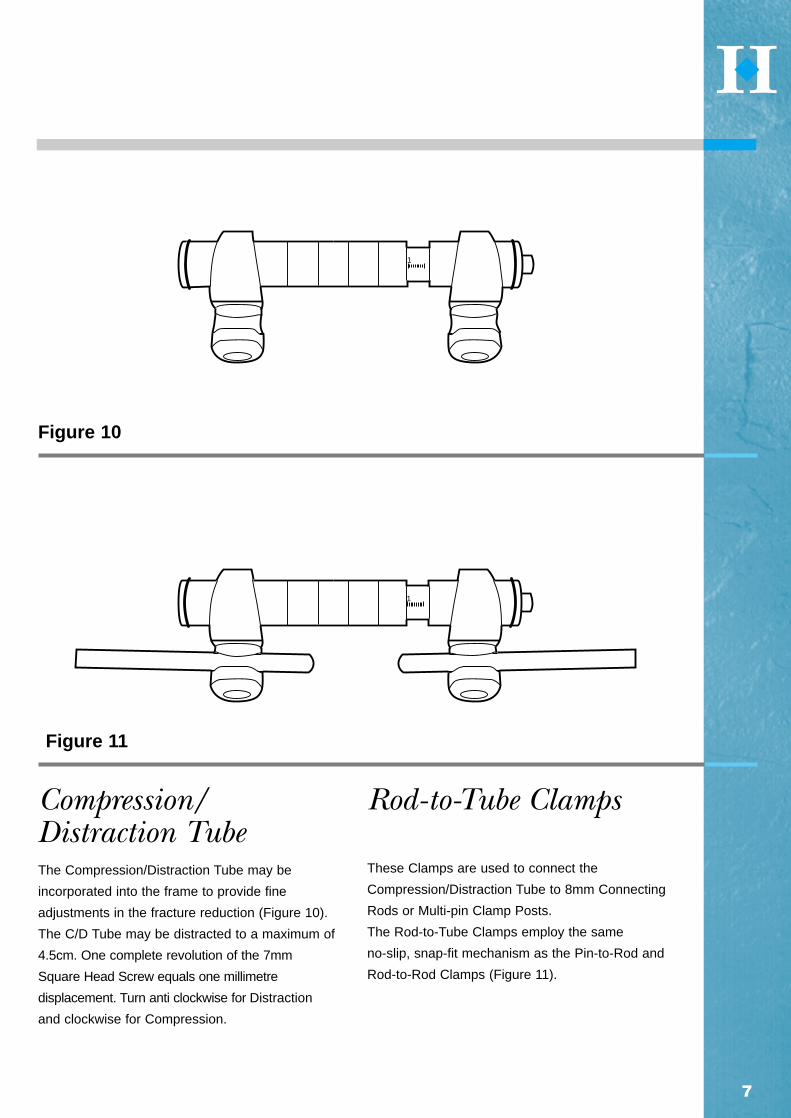
Compression/Distraction TubeThe Compression/Distraction Tube may be
incorporated into the frame to provide fine
adjustments in the fracture reduction (Figure 10).
The C/D Tube may be distracted to a maximum of
4.5cm. One complete revolution of the 7mm
Square Head Screw equals one millimetre
displacement. Turn anti clockwise for Distraction
and clockwise for Compression.
Rod-to-Tube Clamps
These Clamps are used to connect the
Compression/Distraction Tube to 8mm Connecting
Rods or Multi-pin Clamp Posts.
The Rod-to-Tube Clamps employ the same
no-slip, snap-fit mechanism as the Pin-to-Rod and
Rod-to-Rod Clamps (Figure 11).
7
Figure 10
Figure 11
1
1
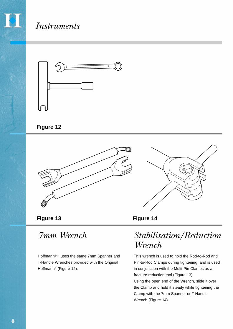
7mm Wrench
Hoffmann® II uses the same 7mm Spanner and
T-Handle Wrenches provided with the Original
Hoffmann® (Figure 12).
Stabilisation/ReductionWrenchThis wrench is used to hold the Rod-to-Rod and
Pin-to-Rod Clamps during tightening, and is used
in conjunction with the Multi-Pin Clamps as a
fracture reduction tool (Figure 13).
Using the open end of the Wrench, slide it over
the Clamp and hold it steady while tightening the
Clamp with the 7mm Spanner or T-Handle
Wrench (Figure 14).
Figure 13
Figure 12
Instruments
Figure 14
8

To use as a reduction tool, Apex® Half Pins and the
Multi-Pin Clamps are put in place (Figure 15).
Medially, build the frame, but leave all components
loose (Figure 16). Insert the Stabilisation/Reduction
Wrench (Figure 17) in the post hole and reduce the
fracture, tighten all medial components
(Figure 18). Remove Wrenches and assemble
frame laterally. Finally tighten all the components.
Figure 15
Figure 16
9
Figure 18
Figure 17
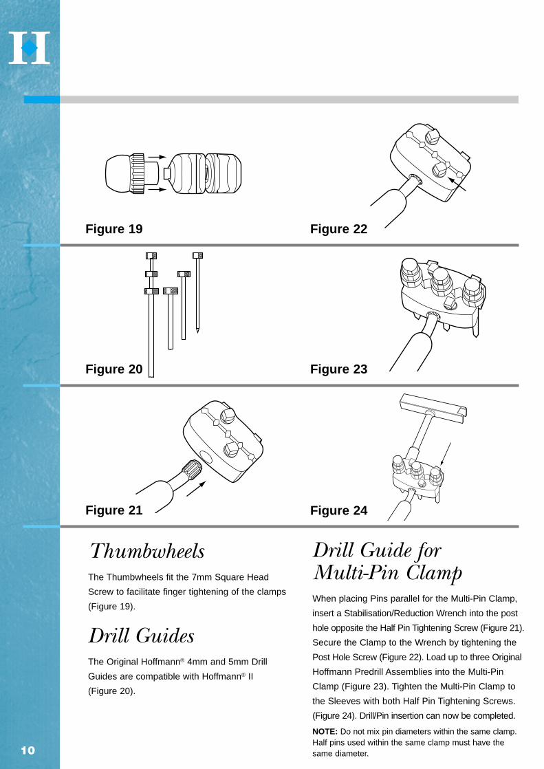
ThumbwheelsThe Thumbwheels fit the 7mm Square Head
Screw to facilitate finger tightening of the clamps
(Figure 19).
Drill Guides The Original Hoffmann® 4mm and 5mm Drill
Guides are compatible with Hoffmann® II
(Figure 20).
Drill Guide for Multi-Pin ClampWhen placing Pins parallel for the Multi-Pin Clamp,
insert a Stabilisation/Reduction Wrench into the post
hole opposite the Half Pin Tightening Screw (Figure 21).
Secure the Clamp to the Wrench by tightening the
Post Hole Screw (Figure 22). Load up to three Original
Hoffmann Predrill Assemblies into the Multi-Pin
Clamp (Figure 23). Tighten the Multi-Pin Clamp to
the Sleeves with both Half Pin Tightening Screws.
(Figure 24). Drill/Pin insertion can now be completed.
NOTE: Do not mix pin diameters within the same clamp.Half pins used within the same clamp must have thesame diameter.
Figure 21
Figure 19 Figure 22
Figure 20 Figure 23
Figure 24
10

Figure 25
Figure 26
Figure 27
Clamp Connection Weight-bearing Connection
11
Hoffmann® II FrameRecommendations1. Fully open the Rod-to-Rod and Pin-to-Rod
Clamps prior to attachment of the component to
the frame (Figure 25).
2. Do not place Rod-to-Rod or Pin-to-Rod Clamps
on the curved portions of the Curved Rod or 30°
Angled Post (Figure 26).
3. All 7mm Square Head Screws should be
positioned facing away from the patient and other
frame components to make tightening more
accessible (Figure 27).
4. When possible, place the Rod-to-Rod and
Pin-to-Pin Clamps on the inside of the frame and
facing the fracture to increase stability (Figure 29).
5. Connecting Rods should always be kept as
short as possible in order to maximise frame
stability.
6. Do not bend Hoffmann II Aluminium or Carbon
Connecting Rods.
7. Always use Stryker® Howmedica Apex® External
Fixation Pins with the Hoffmann II External
Fixation System.
8. As with all external fixation frames, the frame
must be adapted to the weight and fracture
patterns of the patient.
9. The Rod-to-Rod and Pin-to-Rod Clamps must
be opened completely prior to cleaning and
sterilisation.
10. The posts must be removed from the Multi-Pin
Clamp Assembly prior to cleaning and sterilisation.
11. Precise reduction is not required prior to Pin
insertion. The frame can be assembled and the
final reduction performed with the frame in situ
before all components are locked in place.
12. Hoffmann II is only compatible with Stryker®
Howmedica’s Original Hoffmann®, Monotube®
Triax™, and Monticelli-Spinelli™ External Fixation
Systems.
Frame Applications
✗✓
✗✓

Assembly. (The Multi-Pin Clamp should be used
as a guide for parallel placement of the Pins.) Two
30° Angled Posts are inserted into the
Multi-Pin Clamps in an inverted “V” position.
Connect the Multi-Pin Clamp assembly to the
Curved Rod with two 8mm Connecting Rods and
four Rod-to-Rod Clamps.
Pin-to-Rod and Rod-to-Rod Clamps should be
placed on the inside of the frame, facing the
fracture, and not placed on the curved portions of
the Curved Rod or 30° Angled Post.
Qty. Cat. No. Description
1 5029-7 Series Curved Rod (small, medium, or large in aluminium or carbon)
2 5029-8 Series 8mm Connecting Rod (stainless steel, aluminium, or carbon)
3 4920-1-020 Pin-to-Rod Clamp
4 4920-1-010 Rod-to-Rod Clamp
1 4920-2-020 Multi-Pin Clamp Assembly
2 4920-2-140 30° Angled Post
5 5018 Series 5mm Apex® Half Pin
Place three 5mm Apex® Half Pins independently
in the proximal tibia using the Curved Rod as a
guide. Connect all Single Pins to the Curved Rod
using Pin-to-Rod Clamps. 5mm Apex Half Pins
are placed in the tibial diaphysis using classical
parallel Pin placement with the Multi-Pin Clamp
12
Proximal Tibia Semicircular Frame

13
Qty. Cat. No. Description
2 5029-8 Series 8mm Connecting Rod (stainless steel, aluminium, or carbon)
2 4920-2-020 Multi-Pin Clamp Assembly
4 4920-2-140 30° Angled Post
4 4920-1-010 Rod-to-Rod Clamp
4 5018 Series 5mm Apex® Half Pin
5mm Apex® Half Pins are placed in the tibia using
classical parallel Pin placement. (The Multi-Pin
Clamp should be used as a guide for parallel
placement of the Pin.) Four 30° Angled Posts are
inserted into the Multi-Pin Clamp in an inverted
“V” position. Connect the two Pin Clamp
Assemblies using four Rod-to-Rod Clamps and
two 8mm Connecting Rods of the appropriate
length and material. Since precise reduction is not
required prior to Pin insertion, the frame can be
assembled and the final reduction can be
performed with the frame in situ before all
components are locked in place.
If greater stability is required or a bony fragment
must be stabilised, use two additional Rod-to-Rod
Clamps and an 8mm Connecting Rod to join the
medial and lateral Connecting Rods. Capture the
bony fragment with a 5mm Apex Half Pin and
attach to the transverse 8mm Connecting Rod
with a Pin-to-Rod Clamp.
Pin-to-Rod and Rod-to-Rod Clamps should be
placed on the inside of the frame, facing the
fracture, and not placed on the curved portions of
the Curved Rod or 30° Angled Post.
Tibial Shaft Unilateral Frames

Qty. Cat.No. Description
2 5029-8 Series 8mm Connecting Rod (stainless steel, aluminium, or carbon)
1 4920-2-020 Multi-Pin Clamp Assembly
2 4920-2-140 30° Angled Post
2 4920-1-010 Rod-to-Rod Clamp
2 4920-1-020 Pin-to-Rod Clamp
4 5018 Series 5mm Apex® Half Pin
This frame is for extra-articular and distal tibial
fractures close to the joint. It may be supplemented
with internal fixation. 5mm Apex® Half Pins are
placed in the tibial diaphysis using classical parallel
Pin placement. (The Multi-Pin Clamp should be
used as a guide for parallel Pin placement).
Two 30° Angled Posts are inserted into the Multi-Pin
Clamp in an inverted “V” position. Independent Pin
placement is in the antero-medial and lateral
planes of the tibia using 5mm Apex Half Pins.
Connect the Proximal Pin Clamp assembly to the
Distal Pins using Pin-to-Rod and Rod-to-Rod Clamps
and the appropriate length Connecting Rods.
Pin-to-Rod and Rod-to-Rod Clamps should be
placed on the inside of the frame, facing the
fracture, and not placed on the curved portions
of the Curved Rod or 30° Angled Post.
14
Distal Tibia Independent Pin Placement

15
Qty. Cat.No. Description
1 5029-7 Series Curved Rod (small, medium, or large in aluminium or carbon)
2 5029-8 Series 8mm Connecting Rod (stainless steel, aluminium, or carbon)
3 4920-1-020 Pin-to-Rod Clamp
4 4920-1-010 Rod-to-Rod Clamp
1 4920-2-020 Multi-Pin Clamp Assembly
2 4920-2-140 30° Angled Post
5 5018 Series 5mm Apex® Half Pin
Place three 5mm Apex® Half Pins independently
in the distal tibia using the Curved Rod as a
guide. Connect all Single Pins to the Curved Rod
using Pin-to-Rod Clamps. 5mm Apex Half Pins
are placed in the tibia using classical parallel Pin
placement. (The Multi-Pin Clamp should be used
as a guide for parallel placement of the Pins).
Two 30° Angled Posts are inserted into the Multi-Pin
Clamp in an inverted “V” position. Connect the
Multi-Pin Clamp Assembly to the Curved
Aluminium Rod with two 8mm Connecting Rods
and four Rod-to-Rod Clamps.
Pin-to-Rod and Rod-to-Rod Clamps should be
placed on the inside of the frame, facing the
fracture, and not placed on the curved portions
of the Curved Rod or 30° Angled Post.
Distal Tibia Semi-Circular Frame

Qty. Cat.No. Description
2 5029-8 Series 8mm Connecting Rod (stainless steel, aluminium, or carbon)
4 4920-1-020 Pin-to-Rod Clamp
4 5023 Series 4mm Apex® Half Pin
This frame provides minimal external fixation for
stabilisation of the humerus. It is useful for
fractures near the joints. Independent Pin
placement of two proximal Apex® Half Pins in the
lateral and/or posterior aspect of the distal humerus
is performed. Connect all Single Pins to two 8mm
Connecting Rods using Pin-to-Rods Clamps.
Pin-to-Rod and Rod-to-Rod Clamps should be
placed on the inside of the frame, facing the
fracture, and not placed on the curved portions
of the Curved Rod or 30° Angled Post.
16
Humeral Fractures Independent Pin Placement

17
Qty Cat.No. Description
1 5029-8 Series 8mm Connecting Rod (stainless steel, aluminium, or carbon)
2 4920-2-020 Multi-Pin Clamp Assembly
2 4920-2-140 30° Angled Post
2 4920-1-010 Rod-to-Rod Clamp
4 5023 Series 4mm Apex® Half Pin
4mm Apex® Half Pins are placed in the humeral
diaphysis using classical parallel pin placement of
Two Pin Clamp Assemblies. (The Multi-Pin Clamp
Assembly should be used as a guide for pin
insertion to guarantee parallel pin placement.)
Two 30° Angled Posts are inserted into the Multi-Pin
Clamp in an inverted “V” position. The Proximal
Pins should be placed in the lateral and/or
posterior aspects of the humerus. Connect the
Two Pin Clamp Assemblies together using two
Rod-to-Rod Clamps and an 8mm Connecting Rod
of the proper length. Since precise reduction is not
required prior to Pin insertion, the frame may be
assembled and the final reduction made with the
frame in situ.
If a bony fragment must be stabilised, capture the
fragment with an additional 4mm Apex Half Pin
and connect to the 8mm Connecting Rod with a
Pin-to-Rod Clamp.
Pin-to-Rod and Rod-to-Rod Clamps should be
placed on the inside of the frame, facing the
fracture, and not placed on the curved portions
of the Curved Rod or 30° Angled Post.
Humeral Shaft Fractures Unilateral Frame
18
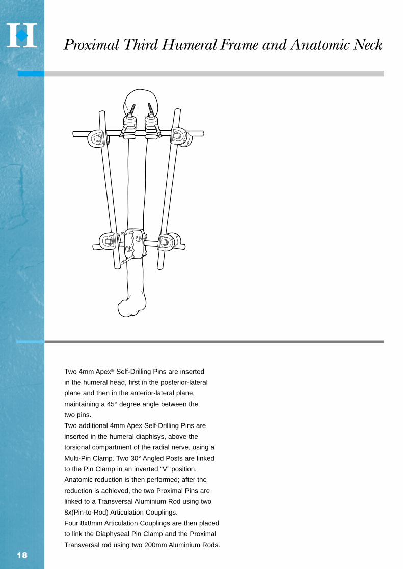
Two 4mm Apex® Self-Drilling Pins are inserted
in the humeral head, first in the posterior-lateral
plane and then in the anterior-lateral plane,
maintaining a 45° degree angle between the
two pins.
Two additional 4mm Apex Self-Drilling Pins are
inserted in the humeral diaphisys, above the
torsional compartment of the radial nerve, using a
Multi-Pin Clamp. Two 30° Angled Posts are linked
to the Pin Clamp in an inverted “V” position.
Anatomic reduction is then performed; after the
reduction is achieved, the two Proximal Pins are
linked to a Transversal Aluminium Rod using two
8x(Pin-to-Rod) Articulation Couplings.
Four 8x8mm Articulation Couplings are then placed
to link the Diaphyseal Pin Clamp and the Proximal
Transversal rod using two 200mm Aluminium Rods.
Proximal Third Humeral Frame and Anatomic Neck
Qty Cat.No. Description
2 5029-8 Series 8mm Connecting Rods (stainless Steel, aluminium, or carbon)
3 4920-1-020 Pin-to-Rod Clamp
1 4920-1-010 Rod-to-Rod Clamp
2 5018 Series 5mm Apex® Half Pin
1 5023 Series 4mm Apex® Half Pin
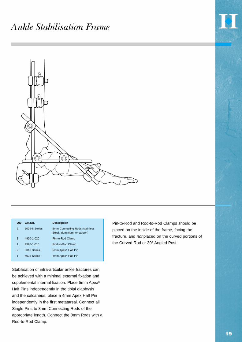
Stabilisation of intra-articular ankle fractures can
be achieved with a minimal external fixation and
supplemental internal fixation. Place 5mm Apex®
Half Pins independently in the tibial diaphysis
and the calcaneus; place a 4mm Apex Half Pin
independently in the first metatarsal. Connect all
Single Pins to 8mm Connecting Rods of the
appropriate length. Connect the 8mm Rods with a
Rod-to-Rod Clamp.
Pin-to-Rod and Rod-to-Rod Clamps should be
placed on the inside of the frame, facing the
fracture, and not placed on the curved portions of
the Curved Rod or 30° Angled Post.
19
Ankle Stabilisation Frame
Qty Cat.No. Description
2 5029-8 Series 8mm Connecting Rods (stainless steel, aluminium, or carbon)
3 4920-2-020 Multi-Pin Clamp Assembly
4 4920-2-140 30° Angled Post
4 4920-1-010 Rod-to-Rod Clamp
2 5030 Series 4mm Apex® Transfixing Pin
2 5018 Series 5mm Apex® Half Pin
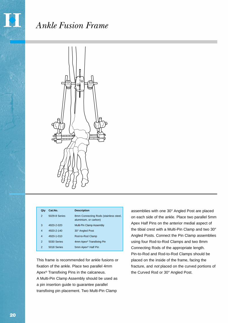
This frame is recommended for ankle fusions or
fixation of the ankle. Place two parallel 4mm
Apex® Transfixing Pins in the calcaneus.
A Multi-Pin Clamp Assembly should be used as
a pin insertion guide to guarantee parallel
transfixing pin placement. Two Multi-Pin Clamp
assemblies with one 30° Angled Post are placed
on each side of the ankle. Place two parallel 5mm
Apex Half Pins on the anterior medial aspect of
the tibial crest with a Multi-Pin Clamp and two 30°
Angled Posts. Connect the Pin Clamp assemblies
using four Rod-to-Rod Clamps and two 8mm
Connecting Rods of the appropriate length.
Pin-to-Rod and Rod-to-Rod Clamps should be
placed on the inside of the frame, facing the
fracture, and not placed on the curved portions of
the Curved Rod or 30° Angled Post.
20
Ankle Fusion Frame

Qty. Cat.No. Description
2 5029-8 Series 8mm Connecting Rods (stainless steel, aluminium or carbon)
2 4920-2-020 Multi-Pin Clamp Assembly
4 4920-2-140 30° Angled Post
4 4920-1-010 Rod-to-Rod Clamp
8 5018 Series 5mm Apex® Half Pin
This frame is recommended for polytrauma
patients and Grade III open fractures. Use the
Multi-Pin Clamp assembly as a guide when
placing the 5mm Apex® Half Pins in the
lateral plane of the femur. Capture pins with the two
Multi-Pin Clamp assemblies and four 30° Angled
Posts in an inverted “V” position. Connect the two
Multi-Pin Clamps with four Rod-to-Rod Clamps and
two 8mm Connecting Rods of the appropriate length.
If greater stability is required or a bony fragment
must be stabilised, use two additional Rod-to-Rod
Clamps and an 8mm Connecting Rod to join the
medial and lateral Connecting Rods. Capture the
bony fragment with a 5mm Apex Half Pin and
connect to the transverse 8mm Connecting Rod
with a Pin-to-Rod Clamp.
Pin-to-Rod and Rod-to-Rod Clamps should be
placed on the inside of the frame, facing the
fracture, and not placed on the curved portions
of the Curved Rod or 30° Angled Post.
21
Femur Unilateral Frame

Qty. Cat.No. Description
3 5029-8 Series 8mm Connecting Rods (stainless steel, aluminium, or carbon)
2 4920-1-010 Rod-to-Rod Clamp
4 4920-1-020 Pin-to-Rod Clamp
4 5018 Series 5mm Apex® Half Pin
This frame is recommended for temporary fixation
of polytrauma patients and Grade III open
fractures, when internal fixation may not be
indicated. Independent pin placement consists
of two proximal 5mm Apex® Half Pins in the
antero-lateral plane of the proximal femur, and two
5mm Apex Half Pins in the antero-lateral and
lateral plane of the distal femur. Connect all Single
Pins to 8mm Connecting Rods of the appropriate
length using Pin-to-Rod Clamps. Connect the
medial and lateral Connecting Rods with a
transverse 8mm Connecting Rod and two
Rod-to-Rod Clamps.
If a bony fragment must be stabilised, capture the
bony fragment with a 5mm Apex Half Pin and
connect to the transverse 8mm Connecting Rod
with a Pin-to-Rod Clamp.
Pin-to-Rod and Rod-to-Rod Clamps should be
placed on the inside of the frame, facing the fracture,
and not placed on the curved portions of the
Curved Rod or 30° Angled Post.
22
Femur Independent Pin Placement Temporary Frame

23
Pelvis Frame III
Qty. Cat.No. Description
2 5029-8 Series 8mm Connecting Rods (stainless steel, aluminium, or carbon)
2 4920-2-020 Multi-Pin Clamp Assembly
2 4920-2-140 30° Angled Post
4 4920-1-010 Rod-to-Rod Clamp
4 5018 Series 5mm Apex® Half Pin
5mm Apex® Half Pins are placed parallel (using
the Multi-Pin Clamp assembly as a guide) in the
iliac wing at 45° degrees or posterior to the
acetabulum (Pins aimed at the greater
trochanter). This Pin placement offers a better
quantity of bone for the Pins to gain fixation.
Caution should be taken while placing these Pins
to avoid drilling through the medial or lateral walls
of the pelvis. Pin placement should be confirmed
radiographically. Connect Half Pins with a Multi-Pin
Clamp Assembly and one 30° Angled Post. The
half pin nuts on the Multi-Pin Clamp should face
away from the patient for easy tightening. Multi-
Pin Clamp Assemblies are joined with three
Connecting Rods of the
appropriate length and four Rod-to-Rod Clamps.
Rod-to-Rod Clamps should be placed on the
inside of the frame, facing the fracture, and not
placed on the curved portions of the Curved Rod
or 30° degree Angled Post.

24
Catalogue DescriptionNumber
4920-2-020 Pin Clamp Assembly with no Post4920-2-060 10 Hole Pin Clamp Assembly with no Post
4920-1-010 Rod to Rod Coupling 8/8mm
4920-1-020 Pin to Rod Coupling 8/4, 5mm
4920-1-030 Inverted Pin to Rod Coupling 8/4, 5mm
4920-2-140 30° Angled Post, Stainless Steel
4920-2-120 Straight Post, Stainless Steel
5029-8-605 Alum. Connecting Rod 8mm x 65mm5029-8-610 Alum. Connecting Rod 8mm x 100mm5029-8-615 Alum. Connecting Rod 8mm x 150mm5029-8-620 Alum. Connecting Rod 8mm x 200mm5029-8-625 Alum. Connecting Rod 8mm x 250mm5029-8-630 Alum. Connecting Rod 8mm x 300mm5029-8-635 Alum. Connecting Rod 8mm x 350mm5029-8-640 Alum. Connecting Rod 8mm x 400mm5029-8-645 Alum. Connecting Rod 8mm x 450mm5029-8-650 Alum. Connecting Rod 8mm x 500mm
5029-8-805 Carbon Connecting Rod 8mm x 65mm5029-8-810 Carbon Connecting Rod 8mm x 100mm5029-8-815 Carbon Connecting Rod 8mm x 150mm5029-8-820 Carbon Connecting Rod 8mm x 200mm5029-8-825 Carbon Connecting Rod 8mm x 250mm5029-8-830 Carbon Connecting Rod 8mm x 300mm5029-8-835 Carbon Connecting Rod 8mm x 350mm5029-8-840 Carbon Connecting Rod 8mm x 400mm5029-8-845 Carbon Connecting Rod 8mm x 450mm5029-8-850 Carbon Connecting Rod 8mm x 500mm
5029-8-065 Stainless Steel Connecting Rod 8mm x 65mm5029-8-100 Stainless Steel Connecting Rod 8mm x 100mm5029-8-150 Stainless Steel Connecting Rod 8mm x 150mm5029-8-200 Stainless Steel Connecting Rod 8mm x 200mm5029-8-250 Stainless Steel Connecting Rod 8mm x 250mm5029-8-300 Stainless Steel Connecting Rod 8mm x 300mm5029-8-350 Stainless Steel Connecting Rod 8mm x 350mm5029-8-400 Stainless Steel Connecting Rod 8mm x 400mm5029-8-450 Stainless Steel Connecting Rod 8mm x 450mm5029-8-500 Stainless Steel Connecting Rod 8mm x 500mm
5029-7-028 Curved Alum. Rod Semi Circular Small5029-7-030 Curved Alum. Rod Semi Circular Medium5029-7-032 Curved Alum. Rod Semi Circular Large
Products

25
Products
22
4920-9-020 Removable Thumbwheel
4920-9-010 Stabilisation/Reduction Wrench
5054-3-005 T-Wrench
5054-8-009 Spanner Wrench
4920-9-980 Hoffmann® II Case / Large Frame Components
Catalogue DescriptionNumber
5029-7-015 Adjustable Connecting Rod Long5029-7-016 Adjustable Connecting Rod Short
4920-0-000 Dynamisation/Distraction Rod for Hoffmann® II
4920-0-015 Compression/Distraction Rod for Hoffmann® II
4920-1-100 Dynamisation/Distraction Rod to Rod Coupling
Instruments
4920-2-150 O-rings for Hoffmann® II Posts
5150-7-025 O-rings for Hoffmann® II Dynamization / Distraction Tubes
4920-2-175 7mm Screw for Hoffmann® II Pin Clamp Assembly
Spare Parts

26
Hoffmann®IIExternal FixationSystem* SurgicalTechniqueGernot Asche, MDDepartment of TraumatologyRegional Hospital, Freudenstadt
Franz Burny, MD, PhDChairman, Department of Orthopaedic SurgeryCliniques Universitaires de BruxellesHospitale ErasmeUniverité Libre de Bruxelles
Charles M. Court-Brown, MD, FRCS (ORTH.)Consultant Orthopaedic SurgeonRoyal Infirmary of Edinburgh
Gabriele Falzarano, MDAzienda Ospedaliera “Rummo”Benevento
Erkki O. Karaharju, MD, MScDAssociate Professor of Orthopaedics andTraumatologyUniversity of Helsinki
Loren Latta, PE, PhDProfessor and Director of ResearchDepartment of Orthopaedics and RehabilitationUniversity of Miami School of Medicine
David Seligson, MDProfessor, Department of Orthopaedic SurgeryUniversity of LouisvilleHealth Science Center
Gregory Zych, DOAssociate ProfessorChief, Orthopaedic TraumaHealth Science CenterUniversity of Miami School of Medicine

27
Stryker®, Hoffmann®, Hoffmann® II, Apex®, Monotube®, Triax™, Compact™ and Tenxor™are trademarks of Stryker Corporation.
Hoffmann®II Swiss Patent Application: 01-709/94-3. Other Patents Pending. * Patents: EU 385,929; 374,093;Canada 1,193,506; U.S. 5,160,335 and 5,207,676. ** Swiss Patent Application: 02-709/94-3. Other Patents Pending.*** Patents: EU 230,856; Swiss CH 671,150; U.S. 4,978,350.†Data on file at Stryker® Howmedica Osteonics USA.

Manufacturing location5 chemin des AulxCH-1228 Plan-les-OuatesGeneva, SwitzerlandTel: 00 41 22 884 0111Fax:00 41 22 884 0199
Cat No: 5075-1-001
© 2000 Stryker Corporation. All rights reserved.
MANUFACTURER:
Unilateral frame system designed to handle a wide variety of fracturesand limb-lengthening applications. This simple, colour-coded systemoffers both dynamic and carbon tubes for individualised performanceand economy. True simplicity, versatility, and economy.
Modular frames which allow for true independent pin placement.Completely compatible with Original Hoffmann® components, thisnew system improves flexibility and ease-of-use, while enhancingframe economics through minimal componentry. It’s external fixationwith a “snap.”
Designed to complement the anatomy of the distal radius by allowing independentmovement of its clamps in multiple planes. Standard unilateral or bi-lateral bridgingframes for intra-articular fractures and peri-articular non-bridging frames for extra-articular fractures. Fully compatible with the Hoffmann® II System, based on aspring-loaded snap-fit mechanism that improves flexibility and ease-of-use.
The DJD II is a Dynamic Elbow Joint Distractor. Fully compatible withthe Hoffmann® II Compact™ System, it is designed to treat post-traumatic elbow stiffness as well as acute elbow trauma cases.
The Tenxor™ System is a hybrid system providing advanced technologyand ease of application. Fully compatible with Hoffmann® II andMonotube® Triax™, based on a spring-loaded, snap-fit mechanism thatimproves flexibility and ease of use.
Every Fixator incorporates the high quality pin-to-bone interfaceprovided by Apex® Pins. The Apex® Pin cuts more sharply with lesstorque, friction and heat upon insertion improving purchase whileminimising the risk of pin tract problems.† Available in self-drilling andblunt tip designs, only from Stryker® Howmedica Osteonics!
E X T E R N A L F I X A T I O N S Y S T E M
�������® ���™
®
™
�� ����EXTERNAL FIXATION SYSTEM
*
**
***