traffic control during construction operations …
TRANSCRIPT

Page 1 of 40
EXHIBIT A ATTACHMENT 3 EXHIBIT F - Traffic Control
TRAFFIC CONTROL DURING CONSTRUCTION OPERATIONS
The following guidelines shall assist field personnel in determining when and what type of traffic control patterns to use for various situations. These guidelines shall provide for the safe and efficient movement of traffic through work zones and enhance the safety of work forces in the work area.
TRAFFIC CONTROL PATTERNS
Traffic control patterns shall be used when a work operation requires that all or part of any vehicle or work area protrudes onto any part of a travel lane or shoulder. For each situation, the installation of traffic control devices shall be based on the following:
Speed and volume of traffic Duration of operation Exposure to hazards
Traffic control patterns shall be uniform, neat and orderly so as to command respect from the motorist.
In the case of a horizontal or vertical sight restriction in advance of the work area, the traffic control pattern shall be extended to provide adequate sight distance for approaching traffic.
If a lane reduction taper is required to shift traffic, the entire length of the taper should be installed on a tangent section of roadway so that the entire taper area can be seen by the motorist.
Any existing signs that are in conflict with the traffic control patterns shall be removed, covered, or turned so that they are not readable by oncoming traffic.
When installing a traffic control pattern, a Buffer Area should be provided and this area shall be free of equipment, workers, materials and parked vehicles.
Typical traffic control plans 19 through 25 may be used for moving operations such as line striping, pot hole patching, mowing, or sweeping when it is necessary for equipment to occupy a travel lane.
Traffic control patterns will not be required when vehicles are on an emergency patrol type activity or when a short duration stop is made and the equipment can be contained within the shoulder. Flashing lights and appropriate trafficperson shall be used when required.
Although each situation must be dealt with individually, conformity with the typical traffic control plans contained herein is required. In a situation not adequately covered by the typical traffic control plans, the Contractor must contact the Engineer for assistance prior to setting up a traffic control pattern.

Rev. Date 12/16/2015
2 ITEM #0971001A Page 2 of 40
EXHIBIT A ATTACHMENT 3
PLACEMENT OF SIGNS
Signs must be placed in such a position to allow motorists the opportunity to reduce their speed prior to the work area. Signs shall be installed on the same side of the roadway as the work area. On multi-lane divided highways, advance warning signs shall be installed on both sides of the highway. On directional roadways (on-ramps, off-ramps, one-way roads), where the sight distance to signs is restricted, these signs should be installed on both sides of the roadway.
ALLOWABLE ADJUSTMENT OF SIGNS AND DEVICES SHOWN ON THE TRAFFIC CONTROL PLANS
The traffic control plans contained herein show the location and spacing of signs and devices under ideal conditions. Signs and devices should be installed as shown on these plans whenever possible.
The proper application of the traffic control plans and installation of traffic control devices depends on actual field conditions.
Adjustments to the traffic control plans shall be made only at the direction of the Engineer to improve the visibility of the signs and devices and to better control traffic operations. Adjustments to the traffic control plans shall be based on safety of work forces and motorists, abutting property requirements, driveways, side roads, and the vertical and horizontal curvature of the roadway.
The Engineer may require that the traffic control pattern be located significantly in advance of the work area to provide better sight line to the signing and safer traffic operations through the work zone.
Table I indicates the minimum taper length required for a lane closure based on the posted speed limit of the roadway. These taper lengths shall only be used when the recommended taper lengths shown on the traffic control plans cannot be achieved.
TABLE I – MINIMUM TAPER LENGTHS
POSTED SPEED LIMIT MILES PER HOUR
MINIMUM TAPER LENGTH IN FEET FOR A SINGLE LANE CLOSURE
30 OR LESS 180 35 250 40 320 45 540 50 600 55 660 65 780
Rev. Date 12/16/2015
3 ITEM #0971001A Page 3 of 40
EXHIBIT A ATTACHMENT 3
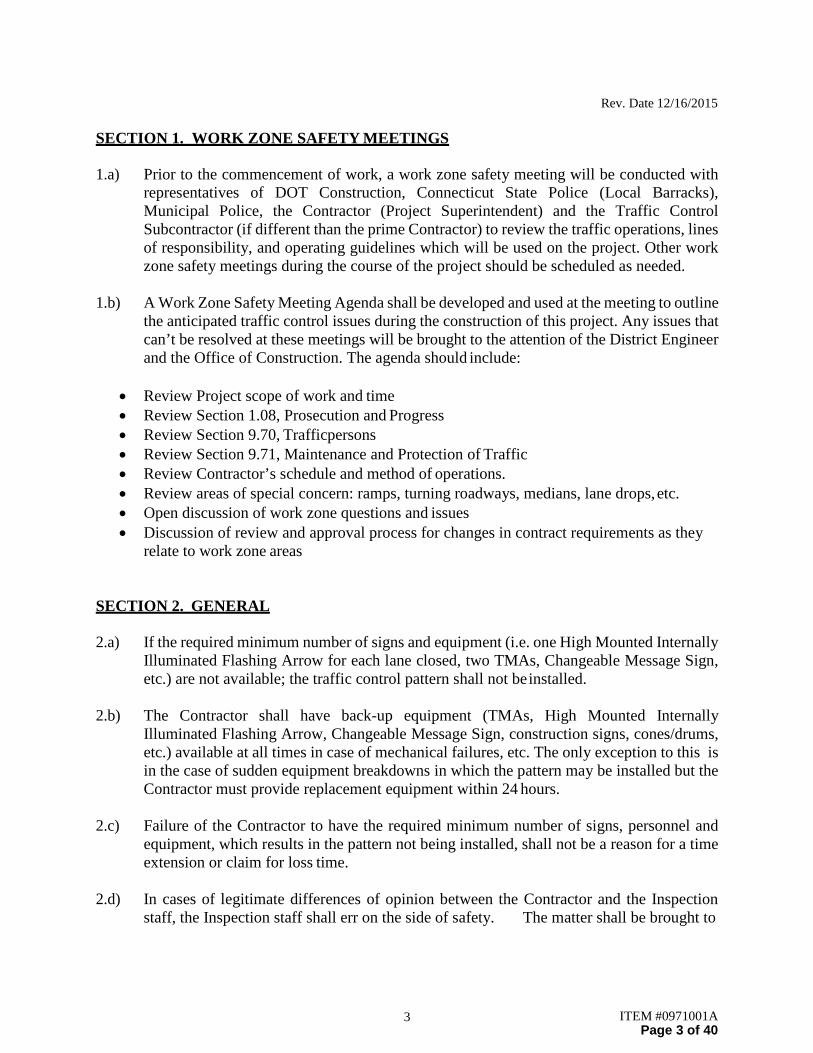
SECTION 1. WORK ZONE SAFETY MEETINGS
1.a) Prior to the commencement of work, a work zone safety meeting will be conducted with representatives of DOT Construction, Connecticut State Police (Local Barracks), Municipal Police, the Contractor (Project Superintendent) and the Traffic Control Subcontractor (if different than the prime Contractor) to review the traffic operations, lines of responsibility, and operating guidelines which will be used on the project. Other work zone safety meetings during the course of the project should be scheduled as needed.
1.b) A Work Zone Safety Meeting Agenda shall be developed and used at the meeting to outline
the anticipated traffic control issues during the construction of this project. Any issues that can’t be resolved at these meetings will be brought to the attention of the District Engineer and the Office of Construction. The agenda should include:
• Review Project scope of work and time • Review Section 1.08, Prosecution and Progress • Review Section 9.70, Trafficpersons • Review Section 9.71, Maintenance and Protection of Traffic • Review Contractor’s schedule and method of operations. • Review areas of special concern: ramps, turning roadways, medians, lane drops, etc. • Open discussion of work zone questions and issues • Discussion of review and approval process for changes in contract requirements as they
relate to work zone areas
SECTION 2. GENERAL
2.a) If the required minimum number of signs and equipment (i.e. one High Mounted Internally Illuminated Flashing Arrow for each lane closed, two TMAs, Changeable Message Sign, etc.) are not available; the traffic control pattern shall not be installed.
2.b) The Contractor shall have back-up equipment (TMAs, High Mounted Internally
Illuminated Flashing Arrow, Changeable Message Sign, construction signs, cones/drums, etc.) available at all times in case of mechanical failures, etc. The only exception to this is in the case of sudden equipment breakdowns in which the pattern may be installed but the Contractor must provide replacement equipment within 24 hours.
2.c) Failure of the Contractor to have the required minimum number of signs, personnel and
equipment, which results in the pattern not being installed, shall not be a reason for a time extension or claim for loss time.
2.d) In cases of legitimate differences of opinion between the Contractor and the Inspection
staff, the Inspection staff shall err on the side of safety. The matter shall be brought to
Rev. Date 12/16/2015
4 ITEM #0971001A Page 4 of 40
EXHIBIT A ATTACHMENT 3
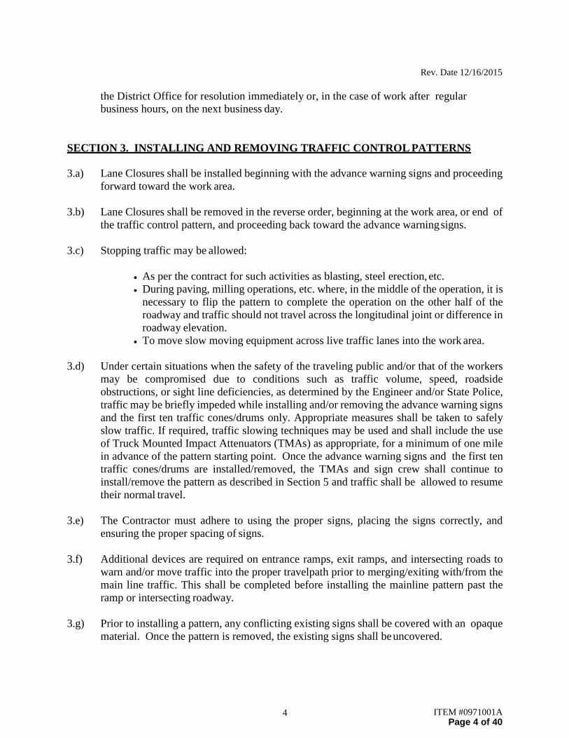
the District Office for resolution immediately or, in the case of work after regular business hours, on the next business day.
SECTION 3. INSTALLING AND REMOVING TRAFFIC CONTROL PATTERNS
3.a) Lane Closures shall be installed beginning with the advance warning signs and proceeding forward toward the work area.
3.b) Lane Closures shall be removed in the reverse order, beginning at the work area, or end of
the traffic control pattern, and proceeding back toward the advance warning signs.
3.c) Stopping traffic may be allowed:
• As per the contract for such activities as blasting, steel erection, etc. • During paving, milling operations, etc. where, in the middle of the operation, it is
necessary to flip the pattern to complete the operation on the other half of the roadway and traffic should not travel across the longitudinal joint or difference in roadway elevation.
• To move slow moving equipment across live traffic lanes into the work area.
3.d) Under certain situations when the safety of the traveling public and/or that of the workers may be compromised due to conditions such as traffic volume, speed, roadside obstructions, or sight line deficiencies, as determined by the Engineer and/or State Police, traffic may be briefly impeded while installing and/or removing the advance warning signs and the first ten traffic cones/drums only. Appropriate measures shall be taken to safely slow traffic. If required, traffic slowing techniques may be used and shall include the use of Truck Mounted Impact Attenuators (TMAs) as appropriate, for a minimum of one mile in advance of the pattern starting point. Once the advance warning signs and the first ten traffic cones/drums are installed/removed, the TMAs and sign crew shall continue to install/remove the pattern as described in Section 5 and traffic shall be allowed to resume their normal travel.
3.e) The Contractor must adhere to using the proper signs, placing the signs correctly, and
ensuring the proper spacing of signs.
3.f) Additional devices are required on entrance ramps, exit ramps, and intersecting roads to warn and/or move traffic into the proper travelpath prior to merging/exiting with/from the main line traffic. This shall be completed before installing the mainline pattern past the ramp or intersecting roadway.
3.g) Prior to installing a pattern, any conflicting existing signs shall be covered with an opaque
material. Once the pattern is removed, the existing signs shall be uncovered.

Rev. Date 12/16/2015
5 ITEM #0971001A Page 5 of 40
EXHIBIT A ATTACHMENT 3
3.h) On limited access roadways, workers are prohibited from crossing the travel lanes to install and remove signs or other devices on the opposite side of the roadway. Any signs or devices on the opposite side of the roadway shall be installed and removed separately.
SECTION 4. USE OF HIGH MOUNTED INTERNALLY ILLUMINATED FLASHING ARROW
4.a) On limited access roadways, one Flashing Arrow shall be used for each lane that is closed. The Flashing Arrow shall be installed concurrently with the installation of the traffic control pattern and its placement shall be as shown on the traffic control plan. For multiple lane closures, one Flashing Arrow is required for each lane closed. If conditions warrant, additional Flashing Arrows should be employed (i.e.: curves, major ramps, etc.).
4.b) On non-limited access roadways, the use of a Flashing Arrow for lane closures is optional.
The roadway geometry, sight line distance, and traffic volume should be considered in the decision to use the Flashing Arrow.
4.c) The Flashing Arrow shall not be used on two lane, two-way roadways for temporary
alternating one-way traffic operations.
4.d) The Flashing Arrow board display shall be in the “arrow” mode for lane closure tapers and in the “caution” mode (four corners) for shoulder work, blocking the shoulder, or roadside work near the shoulder. The Flashing Arrow shall be in the “caution” mode when it is positioned in the closed lane.
4.e) The Flashing Arrow shall not be used on a multi-lane roadway to laterally shift all lanes of
traffic, because unnecessary lane changing may result.
SECTION 5. USE OF TRUCK MOUNTED IMPACT ATTENUATOR VEHICLES (TMAs)
5.a) For lane closures on limited access roadways, a minimum of two TMAs shall be used to install and remove traffic control patterns. If two TMAs are not available, the pattern shall not be installed.
5.b) On non-limited access roadways, the use of TMAs to install and remove patterns closing a
lane(s) is optional. The roadway geometry, sight line distance, and traffic volume should be considered in the decision to utilize the TMAs.
5.c) Generally, to establish the advance and transition signing, one TMA shall be placed on the
shoulder and the second TMA shall be approximately 1,000 feet ahead blocking the lane. The flashing arrow board mounted on the TMA should be in the “flashing arrow” mode when taking the lane. The sign truck and workers should be immediately ahead of

Rev. Date 12/16/2015
6 ITEM #0971001A Page 6 of 40
the second TMA. In no case shall the TMA be used as the sign truck or a work truck. Once the transition is in place, the TMAs shall travel in the closed lane until all Changeable Message Signs, signs, Flashing Arrows, and cones/drums are installed. The flashing arrow board mounted on the TMA should be in the “caution” mode when traveling in the closed lane.
5.d) A TMA shall be placed prior to the first work area in the pattern. If there are multiple work
areas within the same pattern, then additional TMAs shall be positioned at each additional work area as needed. The flashing arrow board mounted on the TMA should be in the “caution” mode when in the closed lane.
5.e) TMAs shall be positioned a sufficient distance prior to the workers or equipment being
protected to allow for appropriate vehicle roll-ahead in the event that the TMA is hit, but not so far that an errant vehicle could travel around the TMA and into the work area. For additional placement and use details, refer to the specification entitled “Type ‘D’ Portable Impact Attenuation System”. Some operations, such as paving and concrete repairs, do not allow for placement of the TMA(s) within the specified distances. In these situations, the TMA(s) should be placed at the beginning of the work area and shall be advanced as the paving or concrete operations proceed.
5.f) TMAs should be paid in accordance with how the unit is utilized. When it is used as a TMA
and is in the proper location as specified, and then it should be paid at the specified hourly rate for “Type ‘D’ Portable Impact Attenuation System”. When the TMA is used as a Flashing Arrow, it should be paid at the daily rate for “High Mounted Internally Illuminated Flashing Arrow”. If a TMA is used to install and remove a pattern and then is used as a Flashing Arrow, the unit should be paid as a “Type ‘D’ Portable Impact Attenuation System” for the hours used to install and remove the pattern, typically 2 hours (1 hour to install and 1 hour to remove), and is also paid for the day as a “High Mounted Internally Illuminated Flashing Arrow”.
SECTION 6. USE OF TRAFFIC DRUMS AND TRAFFIC CONES
6.a) Traffic drums shall be used for taper channelization on limited-access roadways, ramps, and turning roadways and to delineate raised catch basins and other hazards.
6.b) Traffic drums shall be used in place of traffic cones in traffic control patterns that are in
effect for more than a 36-hour duration.
6.c) Traffic Cones less than 42 inches in height shall not be used on limited-access roadways or on non-limited access roadways with a posted speed limit of 45 mph and above.
6.d) Typical spacing of traffic drums and/or cones shown on the Traffic Control Plans in the
Contract are maximum spacings and may be reduced to meet actual field conditions as required.

Rev. Date 12/16/2015
7 ITEM #0971001A Page 7 of 40
SECTION 7. USE OF (REMOTE CONTROLLED) CHANGEABLE MESSAGE SIGNS (CMS)
7.a) For lane closures on limited access roadways, one CMS shall be used in advance of the traffic control pattern. Prior to installing the pattern, the CMS shall be installed and in operation, displaying the appropriate lane closure information (i.e.: Left Lane Closed - Merge Right). The CMS shall be positioned ½ - 1 mile ahead of the lane closure taper. If the nearest Exit ramp is greater than the specified ½ - 1 mile distance, than an additional CMS shall be positioned a sufficient distance ahead of the Exit ramp to alert motorists to the work and therefore offer them an opportunity to take the exit.
7.b) CMS should not be installed within 1000 feet of an existing CMS.
7.c) On non-limited access roadways, the use of CMS for lane closures is optional. The roadway
geometry, sight line distance, and traffic volume should be considered in the decision to use the CMS.
7.d) The advance CMS is typically placed off the right shoulder, 5 feet from the edge of
pavement. In areas where the CMS cannot be placed beyond the edge of pavement, it may be placed on the paved shoulder with a minimum of five (5) traffic drums placed in a taper in front of it to delineate its position. The advance CMS shall be adequately protected if it is used for a continuous duration of 36 hours or more.
7.e) When the CMS are no longer required, they should be removed from the clear zone and
have the display screen cleared and turned 90° away from the roadway.
7.f) The CMS generally should not be used for generic messages (ex: Road Work Ahead, Bump Ahead, Gravel Road, etc.).
7.g) The CMS should be used for specific situations that need to command the motorist’s
attention which cannot be conveyed with standard construction signs (Examples include: Exit 34 Closed Sat/Sun - Use Exit 35, All Lanes Closed - Use Shoulder, Workers on Road - Slow Down).
7.h) Messages that need to be displayed for long periods of time, such as during stage
construction, should be displayed with construction signs. For special signs, please coordinate with the Office of Construction and the Division of Traffic Engineering for the proper layout/dimensions required.
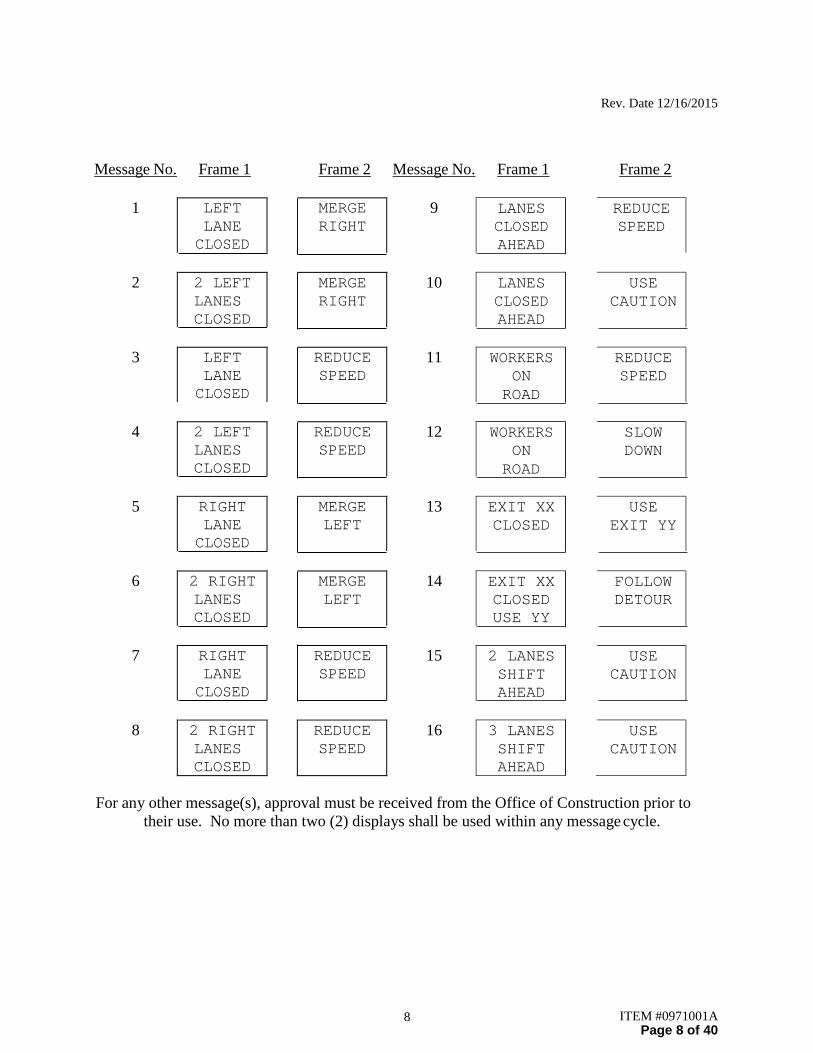
7.i) The messages that are allowed on the CMS are as follows:
Rev. Date 12/16/2015
8 ITEM #0971001A Page 8 of 40
Message No. Frame 1 Frame 2 Message No. Frame 1 Frame 2
1 LEFT LANE CLOSED
MERGE RIGHT
9 LANES CLOSED AHEAD
REDUCE SPEED
2 2 LEFT
LANES CLOSED
MERGE RIGHT
10 LANES CLOSED AHEAD
USE CAUTION
3 LEFT
LANE CLOSED
REDUCE SPEED
11 WORKERS ON
ROAD
REDUCE SPEED
4 2 LEFT
LANES CLOSED
REDUCE SPEED
12 WORKERS ON
ROAD
SLOW DOWN
5 RIGHT
LANE CLOSED
MERGE LEFT
13 EXIT XX CLOSED
USE EXIT YY
6 2 RIGHT
LANES CLOSED
MERGE LEFT
14 EXIT XX CLOSED USE YY
FOLLOW DETOUR
7 RIGHT
LANE CLOSED
REDUCE SPEED
15 2 LANES SHIFT AHEAD
USE CAUTION
8 2 RIGHT
LANES CLOSED
REDUCE SPEED
16 3 LANES SHIFT AHEAD
USE CAUTION
For any other message(s), approval must be received from the Office of Construction prior to their use. No more than two (2) displays shall be used within any message cycle.

Rev. Date 12/16/2015
9 ITEM #0971001A Page 9 of 40
SECTION 8. USE OF STATE POLICE OFFICERS
8.a) State Police may be utilized only on limited access highways and secondary roadways under their primary jurisdiction. One Officer may be used per critical sign pattern. Shoulder closures and right lane closures can generally be implemented without the presence of a State Police Officer. Likewise in areas with moderate traffic and wide, unobstructed medians, left lane closures can be implemented without State Police presence. Under some situations it may be desirable to have State Police presence, when one is available. Examples of this include: nighttime lane closures; left lane closures with minimal width for setting up advance signs and staging; lane and shoulder closures on turning roadways/ramps or mainline where sight distance is minimal; and closures where extensive turning movements or traffic congestion regularly occur, however they are not required.
8.b) Once the pattern is in place, the State Police Officer should be positioned in a non- hazardous location in advance of the pattern If traffic backs up beyond the beginning of the pattern, then the State Police Officer shall be repositioned prior to the backup to give warning to the oncoming motorists. The State Police Officer and TMA should not be in proximity to each other.
8.c) Other functions of the State Police Officer(s) may include:
• Assisting entering/exiting construction vehicles within the work area.
• Enforcement of speed and other motor vehicle laws within the work area, if specifically requested by the project.
8.d) State Police Officers assigned to a work site are to only take direction from the Engineer.

ITEM #971001A Page 10 of 40

ITEM #971001A Page 11 of 40
ITEM #971001A Page 12 of 40
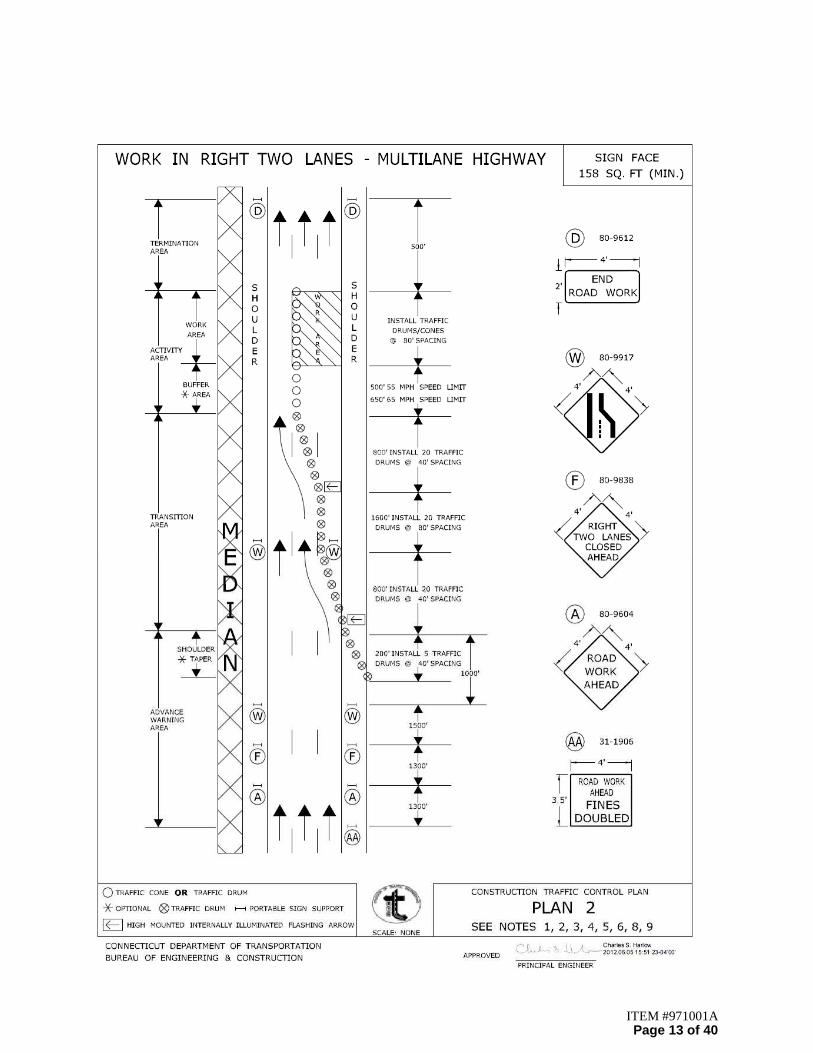
ITEM #971001A Page 13 of 40

ITEM #971001A Page 14 of 40

ITEM #971001A Page 15 of 40
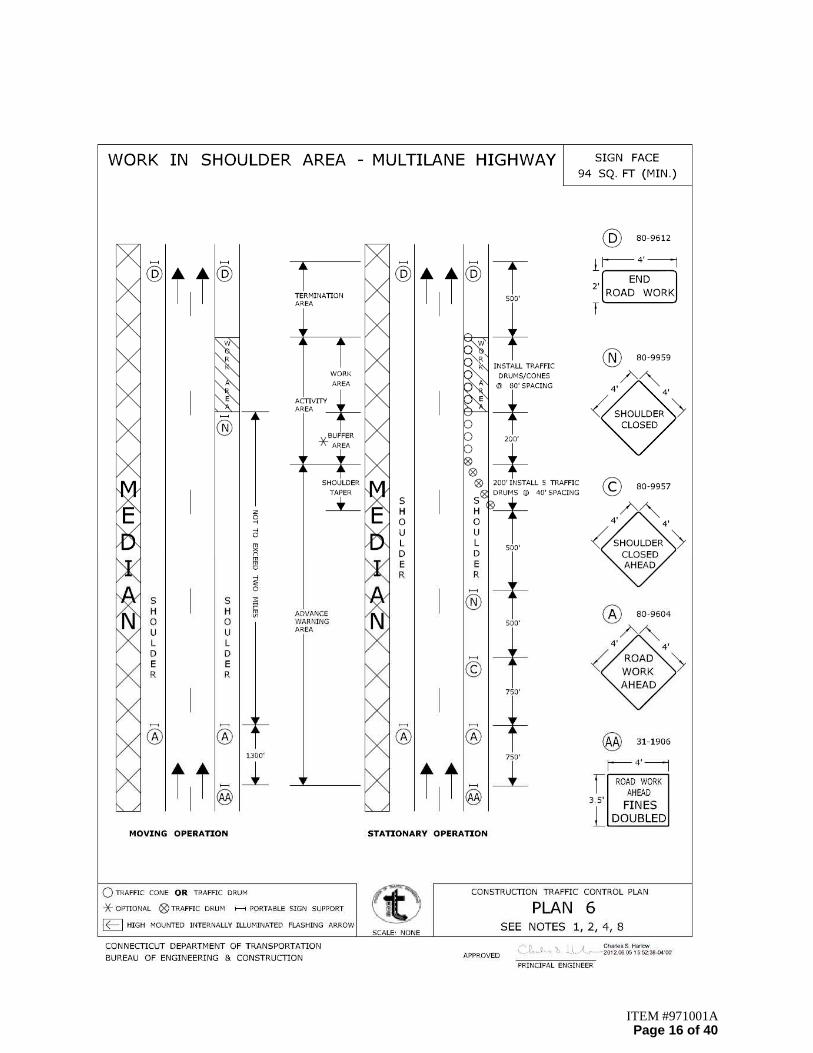
ITEM #971001A Page 16 of 40

ITEM #971001A Page 17 of 40
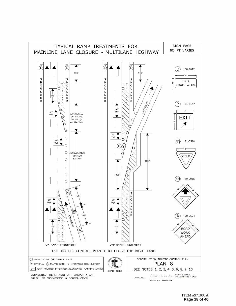
ITEM #971001A Page 18 of 40
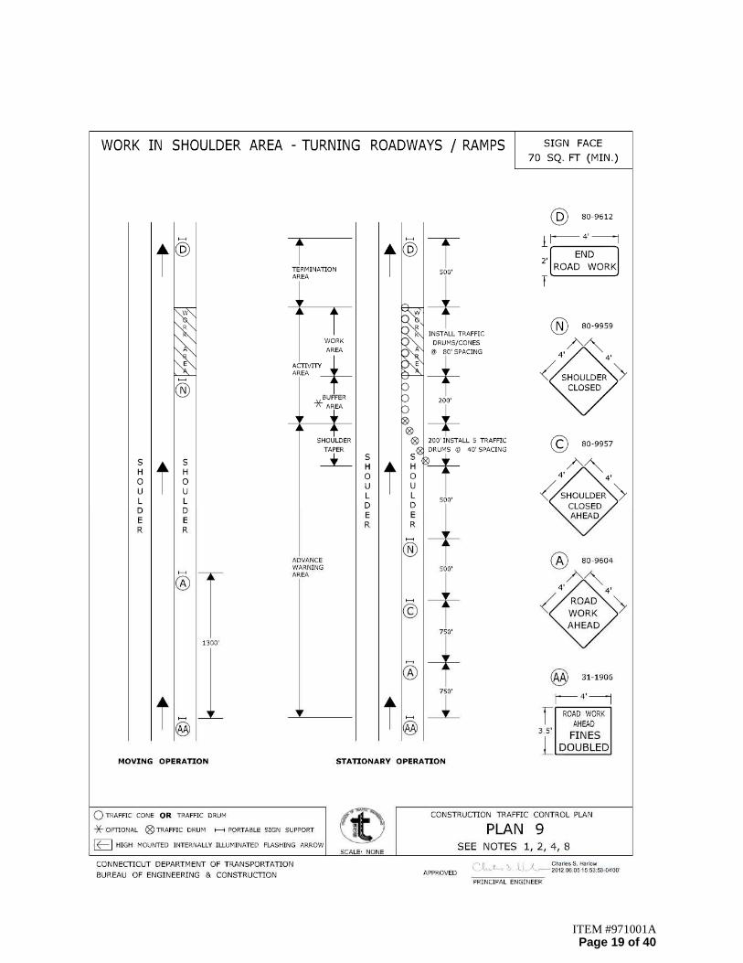
ITEM #971001A Page 19 of 40

ITEM #971001A Page 20 of 40

ITEM #971001A Page 21 of 40

ITEM #971001A Page 22 of 40

ITEM #971001A Page 23 of 40

ITEM #971001A Page 24 of 40
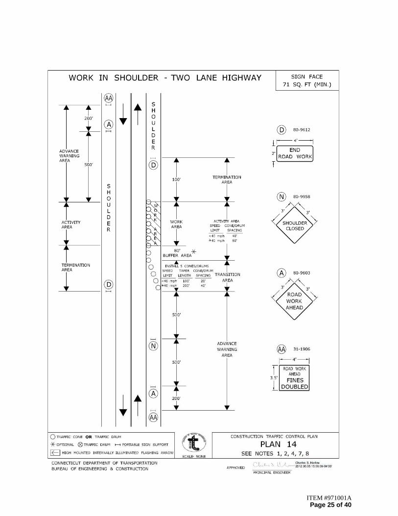
ITEM #971001A Page 25 of 40

ITEM #971001A Page 26 of 40

ITEM #971001A Page 27 of 40

ITEM #971001A Page 28 of 40
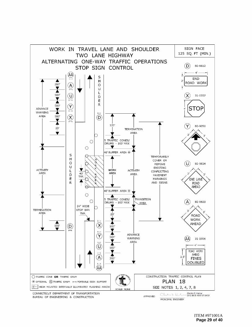
ITEM #971001A Page 29 of 40

ITEM #971001A Page 30 of 40

ITEM #971001A Page 31 of 40
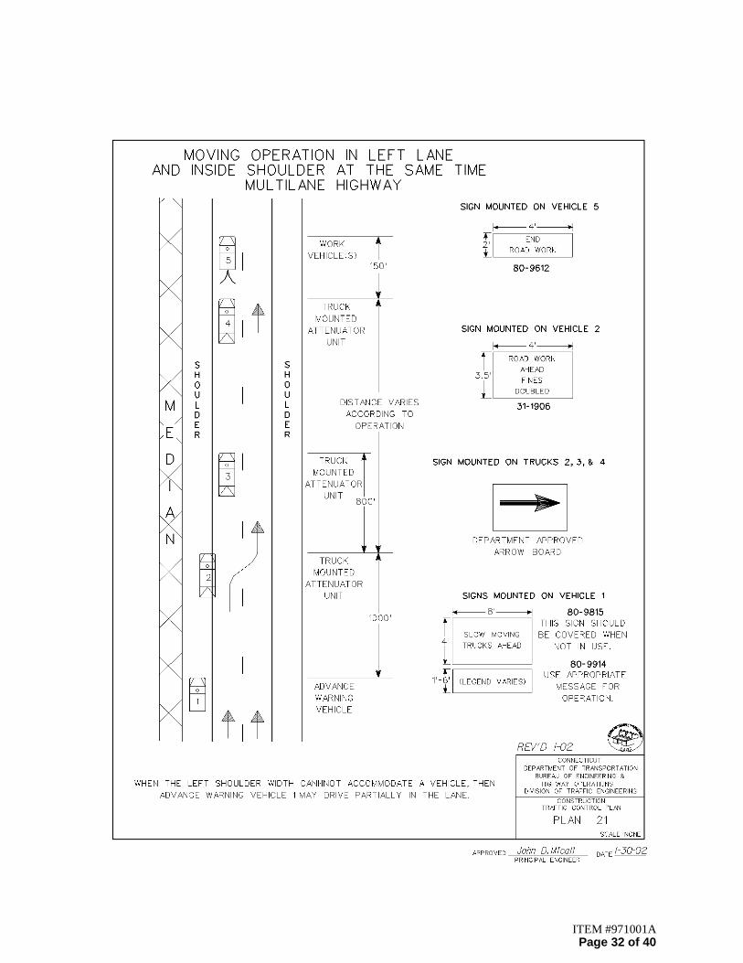
ITEM #971001A Page 32 of 40
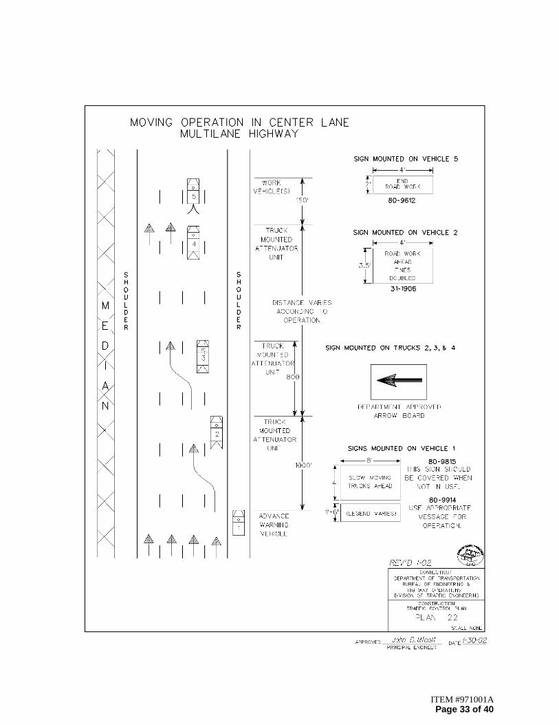
ITEM #971001A Page 33 of 40

ITEM #971001A Page 34 of 40
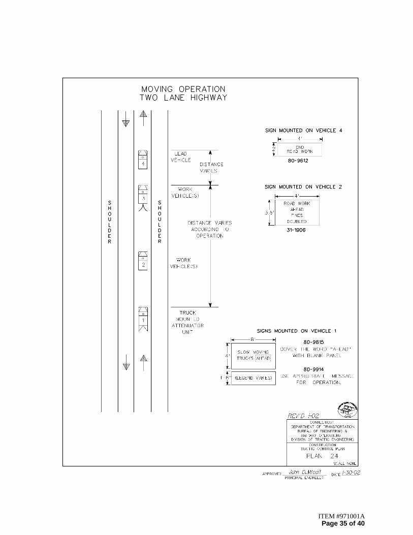
ITEM #971001A Page 35 of 40

ITEM #971001A Page 36 of 40

ITEM #971001A Page 37 of 40
ITEM #971001A Page 38 of 40
ITEM #971001A Page 39 of 40

ITEM #971001A Page 40 of 40