trakfast repair manual - ramset fastening systems
TRANSCRIPT

TRAKFAST REPAIR MANUAL
��Rev. 09/07
Original Nosepiece
TOOL REASSEMBLY
KEY PART NO. DESCRIPTION
24 401313 Air Dam
25 7405171 Combustion Chamber (w/Air Dam)
25A 900234 Cage
26 401330 Chamber Lockout Bar
27 401328 Piston Stop Retaining Ring
28 7502000 Piston Assembly (with Piston Rings)
29 7405055 Piston Rings (pkg. 2)
30 7505109 Bumper
31 404482 O-Ring (Sleeve and Mid-Check
32 403083 Sleeve and Mid-Check Assembly
33 7405056 Seal (1) and Wave Washers (2)
* screws use Loctite 242 (Blue)
KEY PART NO. DESCRIPTION
34 401322 Mid-Check Retaining Ring
35 401488 Cage Spring
37* 092769 Screw, #10-32 x 1/4”
38 7405057 Upper Probe with Grommet
40 7405058 Roll Pins (for Nosepiece Assembly) (pkg. 2)
41 401380 Tie Bar
42 801114A Nosepiece Assembly
43* 7405059 Screw Kit, #10-32 x 3/8” SEMS
45 7505148 Housing with labels
46 7505013 Dust Shield
47* 7405060 Cap Screw & Washer, #10-24 x 1” (pkg. 3)
A

TRAKFAST REPAIR MANUAL
�0Rev. 09/07
TOOL REASSEMBLY
Telescoping Nosepiece
KEY PART NO. DESCRIPTION
24 401313 Air Dam
25 7405171 Combustion Chamber (w/Air Dam & Cage)
25A 900234 Cage
26 401330 Chamber Lockout Bar
27 401328 Piston Stop Retaining Ring
28 7502000 Piston Assembly (with Piston Rings)
29 7405055 Piston Rings (pkg. 2)
30 7505109 Bumper
31 404482 O-Ring (Sleeve and Mid-Check
32 403083 Sleeve and Mid-Check Assembly
33 7405056 Seal (1) and Wave Washers (2)
34 401322 Mid-Check Retaining Ring
35 401488 Cage Spring
*screws - use Loctite 242 (Blue)
KEY PART NO. DESCRIPTION
37* 092769 Screw, #10-32 x 1/4”
38 801132 Upper Probe with Grommet
39 801130A Nosepiece Assembly
40 801131 Guide Block
41 801127 Stop Plate
42 801129 Work Contact Element
43* 7405059 Screw Kit, #10-32 x 3/8” SEMS
44 801128 Lockout Probe
45 7505148 Housing (with labels)
46 7505013 Dust Shield
47 7405060 Cap Screws & Washers, #10-24 x 1” (pkg. 3)
A

TRAKFAST REPAIR MANUAL
��Rev. 09/07
TOOL REASSEMBLY
Magazine Assembly
Place Shear Block in Magazine Assembly (part #7405145).
Secure with screws (part #7405147).
Check Shear Block for any damage.
Place Battery Clip in Magazine Half (part #401422).
Secure with screw (part #401423).
Check for any damage.
Place Battery Contact in Magazine Half (part #7505017).
Notice the position of the Battery Contact. Check for any damaged parts and compressed springs.
Note: In the older style Magazine Assembly you may have to cut a place for the Battery Contact.
Photo to the right shows INCORRECT placement of the ContactAssembly.
Contact should sit flat.

TRAKFAST REPAIR MANUAL
��Rev. 09/07
Place Cover Plate in Magazine Assembly (part #7506006).
Notice position of notch. It should be placed toward the bottom/rear of Magazine.
Place Upper Rail in Magazine Half (part #801112).
Check for any damage.
Check ends of rail for any burrs and check to see if it is bent.
Notice the position of the Upper Rail as it fits into the Shear Block.
Place Carrier Assembly in between Magazine Half.
TOOL REASSEMBLY
Magazine Assembly
Make sure Spring is placed in between the Handle Half so it will slide (part #7405168).
Slide Carrier onto the Post.
Check for any damage.

TRAKFAST REPAIR MANUAL
��Rev. 09/07
Slide Carrier all the way back to the lock position (part #7405168).
Place Magazine Halves together (part #7405149).
Secure with screws .(part #7405070, 3 each)(part #7405071, 1 each)(Shear Block screws, part #7405147)
Slide Lower Rail into Magazine Halves (part #801110).
Check for any damage.
TOOL REASSEMBLY
Magazine Assembly
Replace Foot (part #801113).
Line up the screw holes.
Replace (2) screws (part #7405146).

TRAKFAST REPAIR MANUAL
��Rev. 09/07
TOOL REASSEMBLY
Place Handle Assembly on to the Magazine Assembly. Screw on the Knob. This will hold the handle on the Magazine.
Place Battery in Magazine. You will have a green light. If you have a red light, you will need to check the Battery or the Battery Contact.
Put one finger on the Trigger Button and one finger on the Head Switch Button. Press these at the same time. The fan will start and you will see the spark.
Note: Keep fingers away from fan!
Magazine Assembly
TESTING OPERATION OF HANDLE ASSEMBLY
CAUTION

TRAKFAST REPAIR MANUAL
��Rev. 09/07
TOOL REASSEMBLY
Handle Assembly - part 2
Spark Unit (part #7405163).
Remove any silicone residue from Handle. Place new silicone in Handle.
Press Spark Unit into Handle.
Replace the unit if it does not spark.
Push red wire into Spark Unit and route the wires into the Handle. Insert red wire into Spark Unit noting position of black line.
Place Contact Board into Handle.
Press all the wires into the grooves inside the Handle. Make sure there are no pinches wires that would break contact.
Plug into the Spark Unit.
Make sure the wires are inside the grooves, and not pinched. If they are out of the grooves, the Fuel Cell will not sit properly in Handle.
If Fuel Cell Pad is loose or missing, replace Fuel Cell Pad.

TRAKFAST REPAIR MANUAL
��Rev. 09/07
TOOL REASSEMBLY
Handle Assembly - part 2
Place plastic wire cover over wires.
Make sure all wires are seated properly in handle.vva
Place Trigger Switch on top of the wire cover.
Secure with screws.
Check for any damage.
Press button to make sure it is not sticking.
Plug into Spark Unit.
Check all wires for damage.
Place wire in Handle away from screw holes.
Place Wire Cover over Spark Plug Wire and P.C. Board wires.
Place Cylinder Head on top of Wire Cover and secure with screw.

TRAKFAST REPAIR MANUAL
��Rev. 09/07
TOOL REASSEMBLY
Handle Assembly - part 2
Replace screw if damaged, or if washers are missing. If washers are missing the fuel cell will not sit in handle properly, causing a misfire.
Replace cylinder head if cracked or broken.
Replace O-Ring after cleaning, worn or pinched.
Drop oil on O-Ring. ONLY use TrakFast oil or Paslode Impulse oil (do not use grease).
Replace Fan Blade if bent or if replacing the Fan Motor.
Place Spring in Trigger. Replace if Spring is compressed.
Place Trigger in Handle. Note the position of the Spring.
Do not place on Trigger Switch Button.

TRAKFAST REPAIR MANUAL
��Rev. 09/07
TOOL REASSEMBLY
Handle Assembly - part 2
Place Actuator inside the Handle.
Note the position of the handle.
Replace if broken or damaged.
Check all wires before placing Handle half.
Secure with screws.
Pull Trigger to make sure it is in correct position.
Place Belt Hook on Handle. Secure with screw.
Check to make sure that the washers are on the screw and Cylin-der Head is straight.
If removing Belt Hook, always replace the screw and washers back in the Handle half. This keeps Cylinder Head in position.
Note: If washers are not used or an incorrect screw is used, this may restrict movement of Fuel Cell causing an inoperative tool.
TRAKFAST REPAIR MANUAL
��Rev. 09/07
TOOL REASSEMBLY
Handle Assembly - part 2
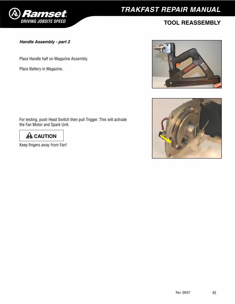
Place Handle half on Magazine Assembly.
Place Battery in Magazine.
For testing, push Head Switch then pull Trigger. This will activate the Fan Motor and Spark Unit.
Keep fingers away from Fan!
CAUTION

TRAKFAST REPAIR MANUAL
�0Rev. 09/07
TOOL REASSEMBLY
Housing Assembly
Place Bumper inside chamber.
If Bumper is loose inside the chamber, replace with new one.
The Bumper is marked “top”. It should be oriented so the word “top” is visible.
Replace O-Ring if it has been pinched, worn or after cleaning.
Lubricate the O-Ring with TrakFast or Paslode Impulse oil (DO NOT use grease).
• Install Flat Seal Washer• Install 2 Wave Washers• Install Retaining Ring
Replace Flat and Wave Washers and clean Mid-Check area if tool does not fire overhead, and Piston does not return.
Be sure Mid-Check area is clean below Seal and Mid-Check washers. The seal of the flat washer is added first, followed by two Wavy Washers then the Snap Ring.
A Mid-Check honing tool is available to “true” up the sealing surface for the Flat Seal Washer.

TRAKFAST REPAIR MANUAL
��Rev. 09/07
TOOL REASSEMBLY
Housing Assembly - (cont’d)
Slide the Combustion Chamber on to Sleeve Mid-Check Assembly.
Check for any damage on parts.
Lubricate sealing surfaces on Combustion Chamber with TrakFast or Paslode oil prior to assembling the sleeve.
Place Lockout Bracket in holes.
Line up the cross on the Sleeve with holes for the Lockout Bracket.
Slide together.
Check Air Dam for any damage.
The widest notch in the Air Dam lines up with the Lockout Bracket.
Place Spring on bottom of Sleeve Assembly. Place Cage over Sleeve.
Check parts for any damage.
Secure with screws, using a T-25. Apply Blue #242 Loctite to screw threads.

TRAKFAST REPAIR MANUAL
��Rev. 09/07
TOOL REASSEMBLY
Housing Assembly - (cont’d)
Check Piston to see if it is bent or tip is worn.Check Piston Rings for damage.Clean inside the grooves.
Check to make sure Piston is not too short. If length is too short, the tool will not shoot overhead or drive fasteners properly.Lubricate Piston Rings and inside of Sleeve Bore with TrakFast or Paslode Impulse oil prior to assembly.
Place Piston inside Sleeve. Always make sure Piston Ring end gaps are opposite of each other.
Tap downward.
With large Snap Ring Pliers, place Retaining Ring into position.
Note orientation of Cage on the Sleeve.
Note: Do not place ends of retaining rings in the vertical notches.

TRAKFAST REPAIR MANUAL
��Rev. 09/07
TOOL REASSEMBLY
Housing Assembly - (cont’d)
Place Nosepiece Assembly on Mid-check Assembly.
Note how parts line up.
Slide Housing over Nosepiece and Mid-check Assembly.
Note the position of the Lockout Bar.
Slide Dust Shield over Nosepiece.
Secure with screws.
Replace if torn or missing.
Do not use tool without Dust Shield. This would cause dust to from inside the tool.
Place Cam inside Handle
Note the position of the hole.

TRAKFAST REPAIR MANUAL
��Rev. 09/07
TOOL REASSEMBLY
Housing Assembly - (cont’d)
Slide Handle Assembly into Housing.
Keep Handle Assembly straight so that the fan does not hit the inside of Chamber.
Line up Cam with Housing.
Place Cam Bushing inside the Cam and Housing.
Note position of Cam in Housing.
Secure with screw. Screwdriver or similar tool may be needed to help align Trigger Cam.
Be sure Cam Bushing goes through hole in Trigger Cam and the hex head of the Bushing is properly seated in the hex recess on the Handle.
Place Cap Assembly on Housing.
Replace any damaged parts.
Secure with screws.
Replace Foam Filter if dirty or torn.
TRAKFAST REPAIR MANUAL
��Rev. 09/07
TOOL REASSEMBLY
Housing Assembly - (cont’d)
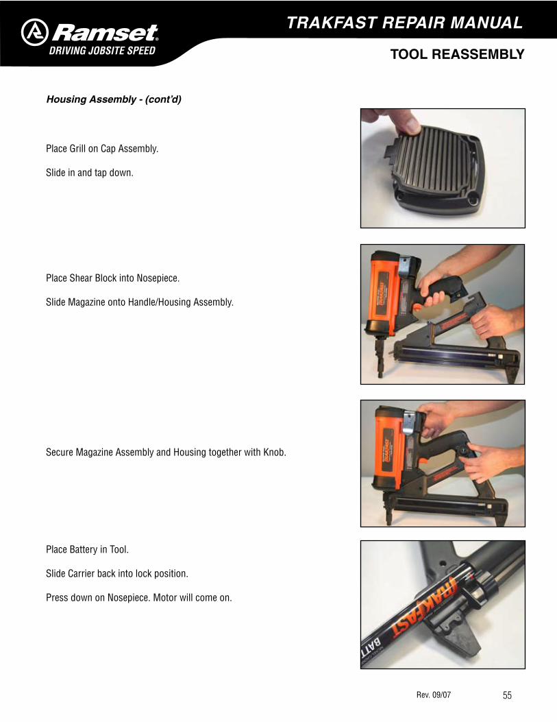
Place Grill on Cap Assembly.
Slide in and tap down.
Place Shear Block into Nosepiece.
Slide Magazine onto Handle/Housing Assembly.
Secure Magazine Assembly and Housing together with Knob.
Place Battery in Tool.
Slide Carrier back into lock position.
Press down on Nosepiece. Motor will come on.

TRAKFAST REPAIR MANUAL
��Rev. 09/07
TOOL REASSEMBLY
Nosepiece Assembly — Original Nose
Original Nose piece (part #801114A).Roll pins (part #7405058).
Check for any damage.
Replace Roll Pins if loose.
Slide Lower Probe in Nosepiece (part #7505057).
Replace Probe if bent or grommet is worn or missing.
Slide Tie Bar into Nosepiece.
Line up with holes.
Place screws into Lower Probe and Tie Bar.
Line up holes and make sure the Lower Probe is fully extended downward. Probe must be all the way extended or tool will not fire.
Secure with Locking Washers and screws. Put Loctite 242 (Blue) on screw threads.
Some probes could be adjusted for length adjust for 3 of the teeth showing.

TRAKFAST REPAIR MANUAL
��Rev. 09/07
TOOL REASSEMBLY
Nosepiece Assembly — Telescoping Nose
Telescoping Nosepiece Assembly (part #801130A).
Check for any damage.
Nose and Flange should be tight and without movement.
Slide Lower Probe into Nosepiece.
Replace Probe if bent or grommet is worn or missing.
Place Guide Block in Nosepiece.
Secure with screws.
Check for damaged parts.

TRAKFAST REPAIR MANUAL
��Rev. 09/07
TOOL REASSEMBLY
Nosepiece Assembly — Telescoping Nose
Slide Lockout Probe onto Work Element.
Check for any damage.
If the Work Element is burred, the fasteners will not flow into the firing position.
Slide Lockout Probe and Work Element onto the Nosepiece.
Place Stop Plate on Nosepiece.
Secure with screws.
Use Loctite #242 (Blue) on screw threads.

TRAKFAST REPAIR MANUAL
��Rev. 09/07
SERVICE BULLETIN
ISSUE DATE: December 4, 2001
SUBJECT: TrakFast Tool (TF1100) Nose Changes
REVISION: All TF1100 tools built since August 2001 (serial #301080281) are equipped with a new style “telescoping nosepiece”. Tools built before August 2001 use what is referred to as the “Standard or Original Nose”.
REASON FOR CHANGE: The “Telescoping Nose” provides improved fastener guidance, thereby increasing fastener “stick” or success rate along with the elimination of plastic jamming in the end of the nose.
ACTION REQUIRED: No action required. Please Note: Magnetic probes used for the TrakFast tool are “nose specific”. See photos below.
Standard or Original Nose with Magnetic Probe (7405151)
Telescoping Nose with Magnetic Probe (7405173)