transmision network
TRANSCRIPT

TRANSMISION NETWORK – RETICULATION STANDARD
ii
DISCLAIMER
This reticulation standard is a sole property of REG and is a guideline to REG field staff and
contractors when executing construction and maintenance in transmission network. It is not
authorized to reprint, retain a copy, disseminate or distribute the information of this REG
reticulation standard. If this is not respected any injury resulting from the inappropriate use, REG
is not responsible.
DOCUMENT CONTROL:
Document Reticulation Standards for Electricity Transmission Network
Planning, Design, Construction, and Operation Maintenance
Feb 2020 Edition #1
March 2021 This Edition #1 shall be reviewed after one year, 2021
TRANSMISION NETWORK – RETICULATION STANDARD
iii
APPROVAL
NAMES TITLE SIGNATURE DATE
Prepared By:
RWIGIMBA Jean
Baptiste
Senior Engineer Standards &
Specifications, EUCL
NYIRINKINDI
Casimir
Standards Specialist, EDCL
NTARE Ronald Quality Assurance Specialist,
EUCL
NIYOMUGABO
LAMECK
Standards & Quality Assurance,
REG
DISI DENYS Ag. Chief Engineer Planning
Checked by: KAZUNGU
Fredrick
Director Energy Planning, EDCL
GAKWAVU
Claver
Director Planning, EUCL
UMUGWANEZA
Clementine
Director Strategic Planning, REG
Approved by: GAKUBA Felix
Managing Director, EDCL
ZINGIRO Armand Ag. Managing Director, EUCL
RON Weiss Chief Executive Officer, REG
TRANSMISION NETWORK – RETICULATION STANDARD
iv
TABLE OF CONTENTS
DISCLAIMER .......................................................................................................................................... II
APPROVAL ............................................................................................................................................. III
TABLE OF CONTENTS ....................................................................................................................... IV
LIST OF FIGURES ............................................................................................................................... VII
LIST OF TABLES ................................................................................................................................. VII
LIST OF ABBREVIATIONS ............................................................................................................. VIII
NORMATIVE REFERENCES ............................................................................................................... X
INTRODUCTION ..................................................................................................................................... 1
PART 1: TRANSMISSION NETWORK PLANNING AND DESIGN ............................................... 2
1.1. PLANNING PHILOSOPHY AND GENERAL GUIDELINES ...................................................... 2
1.2. LOAD FORECAST ............................................................................................................................ 3
1.3. ELECTRICAL TRANSMISSION NETWORK DESIGN .............................................................. 4
1.3.1. Basic design data ............................................................................................................................... 4
1.3.1.1. Electrical Characteristics ................................................................................................................ 4
1.3.1.2. Mechanical Characteristics ............................................................................................................. 4
1.3.2. Transmission line design ................................................................................................................... 5
1.3.2.1. Tower .............................................................................................................................................. 5
1.3.2.1.1. Tower Design .............................................................................................................................. 5
1.3.2.1.1.1. Design Conditions .................................................................................................................... 6
1.3.2.1.2. Structure configuration ................................................................................................................ 8
1.3.2.2. Conductors ...................................................................................................................................... 9
1.3.3.2.1. Transpositions .............................................................................................................................. 9
1.3.3.2.2. Optical Ground Wire (OPGW) .................................................................................................. 10
1.3.3.2.3. Tension of conductor ................................................................................................................. 10
1.3.3.2.4 Ground and phase clearances ..................................................................................................... 10
1.3.3.2.5. Conductor- shield wire spacing ................................................................................................. 11
1.3.3.2.6. Shielding angle .......................................................................................................................... 11
1.3.3.2.7. Aeolian Vibration ...................................................................................................................... 12
1.4. SUBSTATION ................................................................................................................................... 13
1.4.1. Criteria for site selection of substation ............................................................................................ 13
1.4.2. Substation Design Considerations ................................................................................................... 13
1.4.2.1. Power Transformer ....................................................................................................................... 13
1.4.2.2. Substation Conductors & Cables .................................................................................................. 14
1.4.2.3. Bus bar .......................................................................................................................................... 14
1.4.2.4. Voltage transformer (VT) ............................................................................................................. 14
TRANSMISION NETWORK – RETICULATION STANDARD
v
1.4.2.5. Current transformer (CT) .............................................................................................................. 15
1.4.2.6. Circuit Breaker ............................................................................................................................. 16
1.4.2.7. Lightning (Surge) Arrestors .......................................................................................................... 16
1.4.2.8. Disconnector and Earthing Switches ............................................................................................ 16
1.4.2.9. Earthing System ............................................................................................................................ 16
1.4.2.10. Protection system ........................................................................................................................ 16
1.4.2.11. Remote Terminal Unit (RTU) .................................................................................................... 17
1.4.2.12. Disturbance Fault Recorders ...................................................................................................... 17
1.4.2.13. Metering system ......................................................................................................................... 17
PART 2: TRANSMISSION NETWORK CONSTRUCTION ............................................................ 18
2.1. CONSTRUCTION OF TRANSMISSION LINE ........................................................................... 18
2.1.1. Prerequisites:.................................................................................................................................... 18
2.1.2. Overhead line construction process ................................................................................................. 18
18
2.1.3. Tower foundation ............................................................................................................................ 19
2.1.4. Tower erection ................................................................................................................................. 19
2.1.5. Insulator, accessories and fittings .................................................................................................... 20
2.1.6. Conductor stringing ......................................................................................................................... 20
2.1.6.1. Tensioning and sagging of Conductors ........................................................................................ 21
2.1.6.2. Clipping-in .................................................................................................................................... 21
2.1.7. Conductors spacing and clearances ................................................................................................. 21
2.1.7.1. Live metal-structure clearances .................................................................................................... 21
2.1.8. Aircraft warning devices ................................................................................................................. 22
2.1.9. Towers earthing ............................................................................................................................... 22
2.2. CONSTRUCTION OF SUBSTATION ........................................................................................... 23
2.2.1. Pre-requisites ................................................................................................................................... 23
2.2.2. Substation Construction process ...................................................................................................... 23
2.2.3. Civil works ...................................................................................................................................... 24
2.2.4. Installation of substation primary equipment .................................................................................. 24
2.2.4.1. Pre-requisite .................................................................................................................................. 24
2.2.4.2. Disconnector and Earthing Switches ............................................................................................ 24
2.2.4.3. Lightning (Surge) Arrestors .......................................................................................................... 25
2.2.4.4. Voltage Transformer (VT) ............................................................................................................ 25
2.2.4.5. Current Transformers (CT) ........................................................................................................... 25
2.2.4.6. Circuit Breaker ............................................................................................................................. 25
2.2.4.7 Bus bar ........................................................................................................................................... 25
2.2.4.8 Conductors in switchyard .............................................................................................................. 25
2.2.4.9. Power Transformer ....................................................................................................................... 26
2.2.5. Control Building .............................................................................................................................. 26
2.2.6. Substation earthing .......................................................................................................................... 27
TRANSMISION NETWORK – RETICULATION STANDARD
vi
PART 3: MAINTENANCE OF TRANSMISSION NETWORK ........................................................ 28
3.1. PRE-REQUISITE ................................................................................................................................... 28
3.2. MAINTENANCE OF TRANSMISSION LINE ............................................................................................ 28
3.2.1. Preventive/ planned maintenance .................................................................................................... 28
3.2.2. Fault/Curative Maintenance ............................................................................................................ 28
3.3. MAINTENANCE OF SUBSTATION ............................................................................................. 32
3.3.1 Maintenance of outdoor equipment in substation ............................................................................. 32
3.3.1.1. External Cleaning ......................................................................................................................... 33
3.3.1.2. Rust Protection ............................................................................................................................. 33
3.3.1.3. Lubrication .................................................................................................................................... 33
3.3.1.4. Treatment of Contact Surfaces ..................................................................................................... 33
3.3.2. Preventive maintenance activities of main substation equipment ................................................... 34
3.3.2.1. Transformers and Reactors ........................................................................................................... 34
3.3.2.2. Circuit Breakers ............................................................................................................................ 36
3.3.2.3. Current Transformers ................................................................................................................... 38
3.3.2.4. Marshalling Box ........................................................................................................................... 38
3.3.2.5. Voltage (Capacitive) Transformers (VT) ..................................................................................... 39
3.3.2.6. Disconnector/Isolators and Earth Switches .................................................................................. 39
3.3.2.7. Lightning (Surge) Arresters .......................................................................................................... 40
3.3.2.8. Bar, jumpers, connectors, clamps, switchyard illumination, etc. ................................................. 41
3.3.2.9. Capacitors ..................................................................................................................................... 41
3.3.2.10. Protection System ....................................................................................................................... 42
3.3.2.11. Gas Insulated Switchgear (GIS) ................................................................................................. 44
3.3.2.12. Batteries and DC Distribution System ....................................................................................... 45
ANNEX 1 .................................................................................................................................................. 46
ANNEX 2 .................................................................................................................................................. 66

TRANSMISION NETWORK – RETICULATION STANDARD
vii
LIST OF FIGURES
Figure 1: Illustration of basic, wind, uplift and weight span ........................................................................ 7
Figure 2: Typical configurations of conductors of overhead lines on towers (single circuit) ...................... 8
Figure 3: Typical configurations of conductors of overhead lines on towers (double circuit) ..................... 9
LIST OF TABLES
Table 1: Transmission lines reliability levels ref iec 60826 ......................................................................... 2
Table 2: Breaking hv current capacity, ref ieee std c37.04™-2018 ............................................................. 2
Table 3: Capacity of substation in mva according to voltage levels ............................................................ 3
Table 4: Standard classes of the type of towers ............................................................................................ 5
Table 5: Corresponding basic, wind, uplift and weight span for different types of towers ......................... 7
Table 6: Sequence of transposition ............................................................................................................. 10
Table 7: Minimum vertical clearances ....................................................................................................... 10
Table 8: Line clearances ref: bs: 162 and iec 60076-3 ............................................................................... 11
Table 9: Typical minimum requirements for a single conductor ............................................................... 12
Table 10: Knee voltage limits ..................................................................................................................... 15
Table 11: Current burden limits .................................................................................................................. 15
Table 12: Earthing system limits ................................................................................................................ 16
Table 13: Requirements for tower foundation ............................................................................................ 19
Table 14: Standard transmission line maintenance program ...................................................................... 29
Table 15: Transformer and reactor maintenance activities that require no shut down ............................... 34
Table 16: Transformer and reactor maintenance activities that require shut down .................................... 35
Table 17: Maintenance checks for circuit breaker operation...................................................................... 36
Table 18: Maintenance checks for current transformer operation .............................................................. 38
Table 19: Maintenance checks for the marshalling box ............................................................................. 38
Table 20: Maintenance checks for the voltage transformer ........................................................................ 39
Table 21: Maintenance checks for disconnector/isolators and earth switches ........................................... 39
Table 22: Maintenance checks for the lightening (surge) arresters ............................................................ 40
Table 23: Maintenance checks for the bar, jumpers, connectors, clamps, switchyard illumination .......... 41
Table 24: Maintenance checks for the capacitors ....................................................................................... 41
Table 25: Maintenance checks for the protection system ........................................................................... 42
Table 26: Maintenance checks for the batteries and dc distribution system .............................................. 45
TRANSMISION NETWORK – RETICULATION STANDARD
viii
LIST OF ABBREVIATIONS
AC: Alternating current
AAAC: All Aluminium Alloy Conductors
ACI: American Concrete Institute
ACS: Aluminium Clad Steel
ACSR: Aluminium Conductor Steel Reinforced
A/D: Analog to Digital
BCU: Bay control unit
BS: British Standard
BS EN: British Standard European Norm
°C: Centigrade
CB: Circuit breaker
CIGRE: International Council on Large Electric Systems
CT: Current transformer
CVT: Capacitive voltage transformer
DC: Direct current
DS: Disconnect switch
EAS: East African Standard
EHV: Extra High Voltage
EMI: Electromagnetic interference
EDCL: Energy Development Corporation Limited
EUCL: Energy Utility Corporation Limited
FAT: Factory Acceptance Test
HV: High Voltage
Hz: System frequency (Hertz)
ICNIRP: International Commission on Non-Ionizing Radiation Protection
IEC: International Electro-technical Commission
IEEE: Institute of Electrical and Electronic Engineers
IP: Ingress Protection
ISO: International Organization for Standardization
kA: Kilo amperes
TRANSMISION NETWORK – RETICULATION STANDARD
ix
kV: Kilo volt
kVA: Kilo volt amperes
LAN: Local area network
LV: Low Voltage
MCB: Miniature circuit breaker
MVA: megavolt-ampere
MVAr: megavar (1,000,000 vars), the unit for Reactive Power
MVArh: megavar hour
MW: megawatt (1,000,000 watts), the unit for Active Power
MWh: Megawatt hour
NEMA: National Electrical Supplier’s Association
OLTC: On load tap changer
OHGW: Overhead Ground Wire
ONAF: Oil natural Air Forced
ONAN: Oil natural Air Natural
OPGW: Optical Ground Wire
OSHAS: Occupational Health and Safety Assessment Series
REG: Rwanda Energy Group
RFI: Radio frequency interference
RS: Rwanda Standard
RSB: Rwanda Standards Board
RTU: Remote Terminal Unit
rms: Root mean square
SCADA: Supervisory Control and Data Acquisition
SLD: Single line diagram
UPS: Uninterrupted power supply
VT: Voltage transformer
TRANSMISION NETWORK – RETICULATION STANDARD
x
NORMATIVE REFERENCES
The IEC standards are given as reference for construction or for the quality of material. In addition
to the previous, reference is also made to ACI, ACSE, ANSI, ASTM, BSEN, CIGRE, ICEA, IEEE
and ITU & RSB standards.
In case of any conflict with the referred standards and codes, the following order of priority shall be
observed:
a ) R U R A : Guidelines, Codes and Regulations
b) RS, EAS and IEC standards
c) REG Procedure Manual
d) REG Health and Safety operating procedure
b) ACI, ACSE, ANSI, ASTM, BSEN, CIGRE, ICEA, IEEE, ITU and RSB
standards
c) ISO 9001 and ISO 45001:2018
f) Transmission Master Plan for Rwanda
The last edition of the reference Standards shall be applied, unless something to the contrary is
noted, in connection with the General Technical Requirements. Where only one standard under the
set is listed the complete series under the set is applicable.
None other equivalent standard is acceptable. Any standard that is superseded should be updated in
this manual at least once a year.
TRANSMISION NETWORK – RETICULATION STANDARD
1
INTRODUCTION
The purpose of this document is to create a guideline for planning, design, construction, and operation
maintenance of transmission network to be used by REG in-house construction teams as well as
external consultants and contractors in REG. It addresses the standardization of the transmission
network works and related equipment. The aim is to use harmonized and economic equipment with
dynamic technology and standards. The standardization of transmission network construction will also
reduce the amount of different spare parts to be kept for operation and maintenance.
Towers/poles, conductors, hardware and materials meeting other internationally accepted standards,
which ensure an equal or higher quality would be accepted after approval of the responsible engineer.
Scope
This standard cover design, planning, construction and maintenance of transmission network. It does
not cover switching control, relay protection, coordination with telecommunication lines.
The Document is divided into 3 Parts and Annexes:
Transmission Network Planning and Design
Transmission Network Construction Standards
Transmission Network Maintenance Standards
Annexes:
Annex 1: Network Planning and Development Forms
Annex 2: Transmission Network Maintenance Forms
TRANSMISION NETWORK – RETICULATION STANDARD
2
PART 1: TRANSMISSION NETWORK PLANNING AND DESIGN
1.1. PLANNING PHILOSOPHY AND GENERAL GUIDELINES
a) Transmission Network in Rwanda shall meet N-1 contingency criterion.
b) All new transmission lines shall be designed to allow for two operating circuits.
c) A 110kV intermediate voltage must be used for distribution transformation (15 & 30kV).
This separates the distribution network far enough from the international/interconnected
transmission network.
d) Substations must be designed and positioned in accordance with the requirements of the
REG Transmission and Distribution Master Plan.
e) Power cable and protection &control cables shall not be in the same trench.
f) New transmission lines shall be designed with reliability level 2 as illustrated in table 1.
Table 1: Transmission lines reliability levels Ref IEC 60826
Reliability levels in years years
1 50
2 150
3 500
g) The rated rupturing capacity of the circuit breaker in any sub-station shall not be less than 125%
of the maximum fault level at that sub-station. (The 25% margin is intended to take care of the
increase in short circuit levels as the system grows). The standard rated breaking current
capacity of switchgear at different voltage levels are as illustrated in table 2:
Table 2: Breaking HV current capacity, ref IEEE Std C37.04™-2018
Voltage level (kV) Breaking current (kA) Time (s)
220 50 3
110 40 3
15 and 30 31.5 3
(* The rupturing capacity shall be updated according to the network growth)
TRANSMISION NETWORK – RETICULATION STANDARD
3
h) The capacity at any single substation at different voltage levels shall not normally exceed
as illustrated in table 3:
Table 3: Capacity of substation in MVA according to voltage levels
Voltage level(kV) Capacity (MVA)
220 320
110 150
i) Size and number of interconnected transformers in substation shall be planned in such a way
that the outage of any single unit would not normally overload the remaining interconnected
transformers.
j) Reactive power compensation devices shall be installed as far as possible in the high voltage
network with a view to meet the reactive power requirement of actual load close to the load
points. The method for the reactive power compensation to be adopted shall be confirmed by the
design study.
k) All substations shall be equipped with the following:
• Earthing isolators
• Communication infrastructure to facilitate control and command
• Disturbance Fault Recorder
• Smart metering system at all incoming and outgoing feeders.
l) The protection of transmission lines shall be done with single pole auto reclose operable breakers.
m) A bypass with double bus-bar selection shall be used where justified in cases such as
maintenance, test, continuity of service etc...
1.2. LOAD FORECAST
Load forecast is important in the update of the transmission network master plan and shall be based on
load growth, which may occur in the following ways:
a) Extension of existing networks
b) New network construction
c) Addition of Bulk loads
TRANSMISION NETWORK – RETICULATION STANDARD
4
1.3. ELECTRICAL TRANSMISSION NETWORK DESIGN
1.3.1. Basic design data
1.3.1.1. Electrical Characteristics
The electrical characteristics of the transmission network shall be as stated below:
• Nominal Voltages: 220 or 110kV
• Frequency: 50Hz
• The frequency and high voltage variation at any point on the network shall be ±5% of the
nominal voltage and ±1% of the nominal frequency.
• Power frequency withstand 220kV: 460 kV
• Power frequency withstand 110kV: 230 kV
• Rated lightning impulse withstand voltage 220 kV: 1050kV
• Rated lightning impulse withstand voltage 110 kV: 550kV (according to IEC 60071)
• Pollution: I (according to IEC 60815)
• Cree-page distances shall be applicable to insulators, bushings, etc.
• The voltage shall be in accordance with IEC standards (IEC 60038). The following factors shall
determine the choice of voltage:
- Magnitude of the power to be transmitted
- Length of the line
1.3.1.2. Mechanical Characteristics
Mechanical design characteristics of the transmission network shall be as stated below:
• Wind Velocity: 45m/s
• Dynamic wind pressure: 720N/m²
• Maximum Sustained Wind speed: 29m/s
• Tower Design Safety factor: 2.5
• Air Temperatures:
- Maximum outdoor temperature: +40°C
- Minimum outdoor temperature: + 5°C
- Maximum daily average temperature: +30°C
- Annual average temperature: +20°C
• Rainfall: Annual average rainfall: 1,500mm
TRANSMISION NETWORK – RETICULATION STANDARD
5
• Solar Radiation: Maximum solar radiation: 5,200 W/m²
• Air Humidity: Maximum at +35°C: 95%
1.3.2. Transmission line design
1.3.2.1. Tower
Towers shall be self-supporting with a broad base of hot deep galvanized steel lattice type with body
and hillside extensions. The following types of tower shall be designed for REG projects:
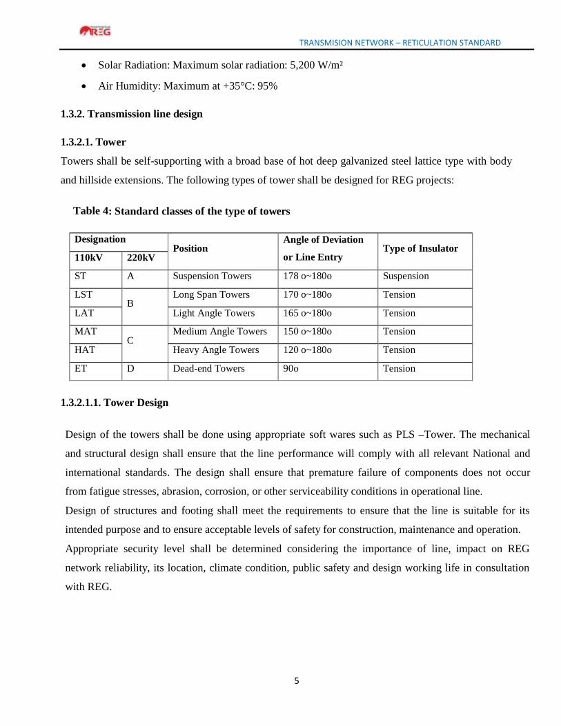
Table 4: Standard classes of the type of towers
Designation
Position Angle of Deviation
or Line Entry
Type of Insulator 110kV 220kV
ST A Suspension Towers 178 o~180o Suspension
LST
B Long Span Towers 170 o~180o Tension
LAT Light Angle Towers 165 o~180o Tension
MAT
C Medium Angle Towers 150 o~180o Tension
HAT Heavy Angle Towers 120 o~180o Tension
ET D Dead-end Towers 90o Tension
1.3.2.1.1. Tower Design
Design of the towers shall be done using appropriate soft wares such as PLS –Tower. The mechanical
and structural design shall ensure that the line performance will comply with all relevant National and
international standards. The design shall ensure that premature failure of components does not occur
from fatigue stresses, abrasion, corrosion, or other serviceability conditions in operational line.
Design of structures and footing shall meet the requirements to ensure that the line is suitable for its
intended purpose and to ensure acceptable levels of safety for construction, maintenance and operation.
Appropriate security level shall be determined considering the importance of line, impact on REG
network reliability, its location, climate condition, public safety and design working life in consultation
with REG.
TRANSMISION NETWORK – RETICULATION STANDARD
6
1.3.2.1.1.1. Design Conditions
a) Assumed Normal-Loading Condition:
The assumed maximum simultaneous working loading on towers shall be as
follows:
i. Vertical loads:
- Tower structures: actual weights of tower structures including accessories
- Power conductors: Weight of conductors of specified weight span with accessories
- Overhead optical fibre earth wire: weight of specified weight span with accessories
- Erection Loads: such loads as workers’ weights on tower members, reaction of temporarily
backstays during stringing operation, etc.
ii. Horizontal Angle Effect
Horizontal angle effect is a horizontal component of maximum working tension conductors and
ea rth wire due to the specified horizontal angle deviation.
iii. Transverse loads i.e. Wind loads, horizontal angle deviation effects
iv. Longitudinal loads i . e . Wind loads, erection loads, maximum working tensions of power
conductors and overhead earth wire for their termination for Type-T tower.
b) Assumed Broken-Wire Condition:
Under this condition, the power conductor or an earth wire is assumed broken at their maximum
working tensions, in addition to the loads under the normal condition. In the case of Type -S tower, the
pull will be assumed to be reduced to 70% of the specified maximum working tensions.
c) Factor of Safety:
The following factors of safety for tower structures shall be applied in the
design:
• 2.5 for the maximum load under the normal loading condition.
• 1.5 for the maximum load under the broken-wire condition. Those factors of safety shall be
proved under tower loading tests on the proto-type towers in the manufacturer’s testing station,
and there should be no failure or permanent distortion during the tests when 100% loading is
sustained for five minutes.
(d) Height of Towers
Height of towers shall be determined using the following
formula: H = Gc + Sg + Li + Hc + Hg
Where,
TRANSMISION NETWORK – RETICULATION STANDARD
7
H = Total height of tower.
Gc =Necessary ground clearance of power conductors above ground or other objectives. Sg =
Maximum conductor sag
Li = Length of a suspension insulator set, but nil for a tension type tower. Hc =
Vertical spacing of upper conductor cross -arm spacing
Hg = Vertical spacing between upper conductor cross-arm and overhead earth wire.
(e) Basic, wind, uplift and weight spans
Basic span is the horizontal distance between centers of adjacent supports on the level ground from
which the height of standard towers is derived with the specified conductor clearances to ground in still
air at maximum temperature.
Wind span is equivalent to half the sum of adjacent horizontal span lengths supported on any one tower.
Uplift weight refers to the weights of conductors and overhead earth wire supported upwards at any
one tower for reinforcing strength of cross arms.
Weight span is the horizontal distance between the lowest points of the conductors, on the two spans
adjacent to the tower.
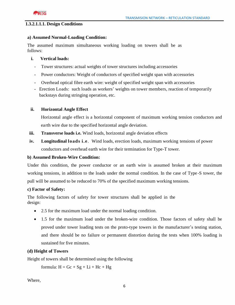
These are clearly illustrated in figure 1 and the requirement for each type of tower presented in table 5
Table 5: Corresponding Basic, Wind, Uplift and Weight Span for different types of towers
Type of Tower S(LT & LST) L(LAT) M(MAT) H/HS(HAT))
T(ET)
Basic Span(m) normal working condition 350 350 350 350 350
Wind span(m) broken wire condition 260 260 260 260 260
Weight Span (m)-Normal working condition 700 1200 1200 1200 1200
Weight Span (m)-Broken wire condition (m) 500 900 900 900 900
Uplift weight for cross arms - 300 300 300 300
Figure 1: Illustration of Basic, Wind, Uplift and Weight Span
TRANSMISION NETWORK – RETICULATION STANDARD
8
1.3.2.1.2. Structure configuration
The configuration of a transmission line tower shall depend on the following factors:
a) Voltage level;
b) Design span;
c) The minimum clearances to be maintained between conductors, and between conductor and
tower, from consideration of the dynamic behavior of conductors and lightning protection of the
line.
d) The type of tower
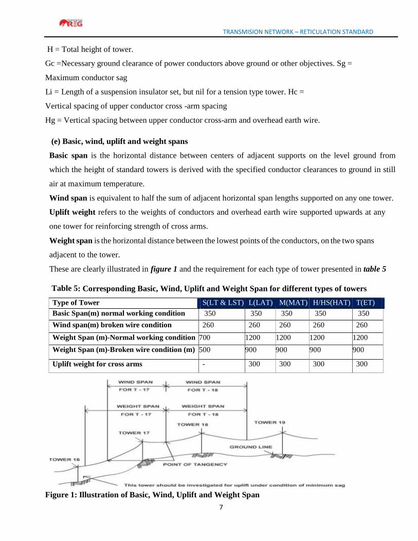
The typical tower configurations having single and double circuits are illustrated below:
Typical configurations of conductors of overhead lines on towers (Single circuit)
Figure 2: Typical configurations of conductors of overhead lines on towers (Single Circuit)
TRANSMISION NETWORK – RETICULATION STANDARD
9
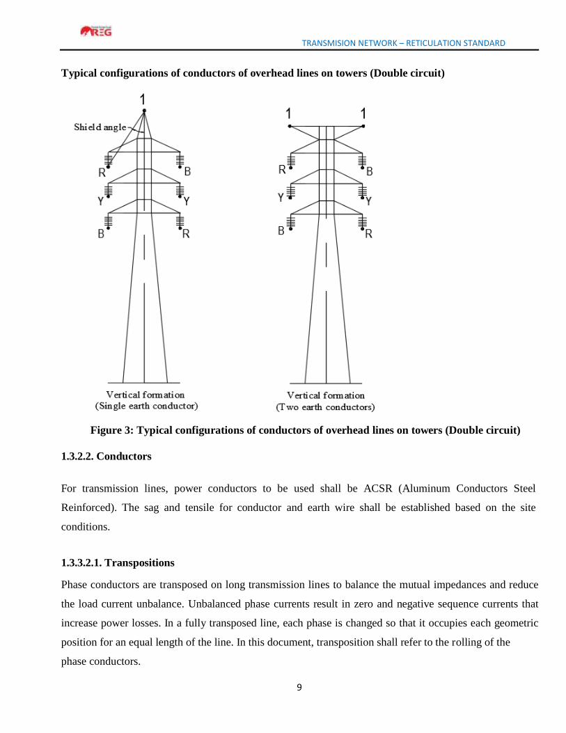
Typical configurations of conductors of overhead lines on towers (Double circuit)
Figure 3: Typical configurations of conductors of overhead lines on towers (Double circuit)
1.3.2.2. Conductors
For transmission lines, power conductors to be used shall be ACSR (Aluminum Conductors Steel
Reinforced). The sag and tensile for conductor and earth wire shall be established based on the site
conditions.
1.3.3.2.1. Transpositions
Phase conductors are transposed on long transmission lines to balance the mutual impedances and reduce
the load current unbalance. Unbalanced phase currents result in zero and negative sequence currents that
increase power losses. In a fully transposed line, each phase is changed so that it occupies each geometric
position for an equal length of the line. In this document, transposition shall refer to the rolling of the
phase conductors.
TRANSMISION NETWORK – RETICULATION STANDARD
10
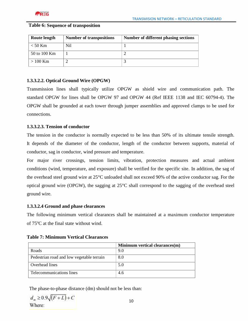
Table 6: Sequence of transposition
Route length Number of transpositions Number of different phasing sections
< 50 Km Nil 1
50 to 100 Km 1 2
> 100 Km 2 3
1.3.3.2.2. Optical Ground Wire (OPGW)
Transmission lines shall typically utilize OPGW as shield wire and communication path. The
standard OPGW for lines shall be OPGW 97 and OPGW 44 (Ref IEEE 1138 and IEC 60794-4). The
OPGW shall be grounded at each tower through jumper assemblies and approved clamps to be used for
connections.
1.3.3.2.3. Tension of conductor
The tension in the conductor is normally expected to be less than 50% of its ultimate tensile strength.
It depends of the diameter of the conductor, length of the conductor between supports, material of
conductor, sag in conductor, wind pressure and temperature.
For major river crossings, tension limits, vibration, protection measures and actual ambient
conditions (wind, temperature, and exposure) shall be verified for the specific site. In addition, the sag of
the overhead steel ground wire at 25°C unloaded shall not exceed 90% of the active conductor sag. For the
optical ground wire (OPGW), the sagging at 25°C shall correspond to the sagging of the overhead steel
ground wire.
1.3.3.2.4 Ground and phase clearances
The following minimum vertical clearances shall be maintained at a maximum conductor temperature
of 75oC at the final state without wind.
Table 7: Minimum Vertical Clearances
Minimum vertical clearances(m)
Roads 9.0
Pedestrian road and low vegetable terrain 8.0
Overhead lines 5.0
Telecommunications lines 4.6
The phase-to-phase distance (dm) should not be less than:
TRANSMISION NETWORK – RETICULATION STANDARD
11
F = Sag of Conductor (m) at maximum temperature (75oC)
L = Length of the insulator string (m), L = 0 for tension string C = Constant for 220 kV = 1.5 m
Special requirements in connection with crossing may be ordered by the client. Where construction
of other types is met, the clearances shall be reviewed and approved.
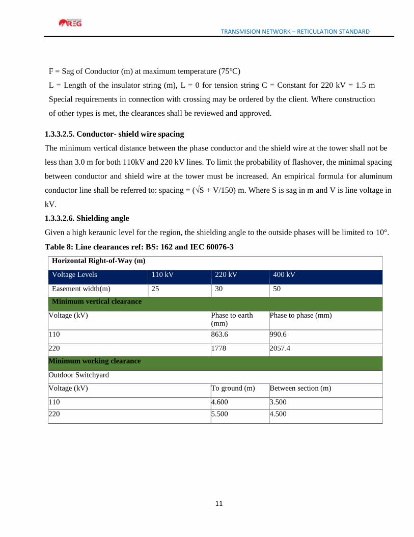
1.3.3.2.5. Conductor- shield wire spacing
The minimum vertical distance between the phase conductor and the shield wire at the tower shall not be
less than 3.0 m for both 110kV and 220 kV lines. To limit the probability of flashover, the minimal spacing
between conductor and shield wire at the tower must be increased. An empirical formula f or aluminum
conductor line shall be referred to: spacing = (√S + V/150) m. Where S is sag in m and V is line voltage in
kV.
1.3.3.2.6. Shielding angle
Given a high keraunic level for the region, the shielding angle to the outside phases will be limited to 10°.
Table 8: Line clearances ref: BS: 162 and IEC 60076-3
Horizontal Right-of-Way (m)
Voltage Levels 110 kV 220 kV 400 kV
Easement width(m) 25 30 50
Minimum vertical clearance
Voltage (kV) Phase to earth (mm)
Phase to phase (mm)
110 863.6 990.6
220 1778 2057.4
Minimum working clearance
Outdoor Switchyard
Voltage (kV) To ground (m) Between section (m)
110 4.600 3.500
220 5.500 4.500
TRANSMISION NETWORK – RETICULATION STANDARD
12
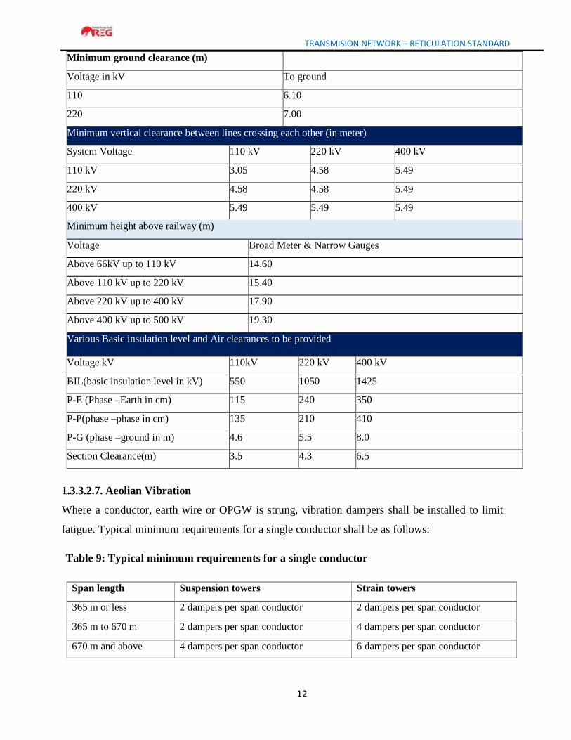
Minimum ground clearance (m)
Voltage in kV To ground
110 6.10
220 7.00
Minimum vertical clearance between lines crossing each other (in meter)
System Voltage 110 kV 220 kV 400 kV
110 kV 3.05 4.58 5.49
220 kV 4.58 4.58 5.49
400 kV 5.49 5.49 5.49
Minimum height above railway (m)
Voltage Broad Meter & Narrow Gauges
Above 66kV up to 110 kV 14.60
Above 110 kV up to 220 kV 15.40
Above 220 kV up to 400 kV 17.90
Above 400 kV up to 500 kV 19.30
Various Basic insulation level and Air clearances to be provided
Voltage kV 110kV 220 kV 400 kV
BIL(basic insulation level in kV) 550 1050 1425
P-E (Phase –Earth in cm) 115 240 350
P-P(phase –phase in cm) 135 210 410
P-G (phase –ground in m) 4.6 5.5 8.0
Section Clearance(m) 3.5 4.3 6.5
1.3.3.2.7. Aeolian Vibration
Where a conductor, earth wire or OPGW is strung, vibration dampers shall be installed to limit
fatigue. Typical minimum requirements for a single conductor shall be as follows:
Table 9: Typical minimum requirements for a single conductor
Span length Suspension towers Strain towers
365 m or less 2 dampers per span conductor 2 dampers per span conductor
365 m to 670 m 2 dampers per span conductor 4 dampers per span conductor
670 m and above 4 dampers per span conductor 6 dampers per span conductor
TRANSMISION NETWORK – RETICULATION STANDARD
13
1.4. SUBSTATION
1.4.1. Criteria for site selection of substation
a) Soil type and conditions
b) Topography
c) Environmental impact assessment shall include but not limited to the following: waste
management, oil spillage, soil or ground water contamination due to oil leakages from
transformers and other oil-filled equipment, obstruction of traffic and destruction of existing
roads, environmental pollution, and electromagnetic fields.
d) Site access
e) Incoming/outgoing line access
f) Size of substation with factor and considerations such as:
- Load growth
- System reliability and stability
- Load transfer in emergency case
- Electricity master plan
1.4.2. Substation Design Considerations
Typical line bay shall have appropriate disconnector, surge arrestor, voltage transformer, current
transformer, circuit breaker, and the second disconnector to the bus bar.
Typical transformer bay shall have the following equipment: disconnector, voltage transformer, surge
arrestor, current transformer, Circuit breaker, post insulators where necessary and HV/MV bushing of the
transformer from which MV underground cables supply indoor MV switchgears. A feeder adaptation unit
(FAU) is required where all LV terminals are collected for supplying all LV circuits for command,
protection and communication from the control room and from the outdoor switchyard.
1.4.2.1. Power Transformer
a) Power transformers in transmission substations shall be rated at minimum 20MVA.
b) Transmission transformer connections shall be done to ensure redundancy.
c) Power transformers shall be designed according to IEC 600273, 60296, 60529, 60076, IEEE
C57.12.90 and IEEE C 57.21.
d) For 220kV voltage transformation shall always be via 110kV.i.e. no voltage transformation shall be
done from high voltage 220kV to distribution voltages of 30kV or 15kV.
TRANSMISION NETWORK – RETICULATION STANDARD
14
e) The transformer base shall be rail based.
f) The transformer oil should be manufactured in accordance with IEC 60296 standard. It shall
be pure hydrocarbon mineral oil, without any additive, gas proof, clean and sufficient free
from moisture and other foreign materials likely to impair its property, with excellent
oxidation stability, high dielectric properties, low temperature properties.
g) The oil-collecting pit for each transformer shall have a capacity for 120 % oil of the
transformer. A water/oil evacuating system using a pump shall be installed for the oil/rain
water collecting pit.
h) OLTC shall always be installed at the primary side of the transformer.
i) The neutral points shall be brought out by suitable means and shall be grounded as per
requirements of the Substation design
1.4.2.2. Substation Conductors & Cables
The conductor used in substation shall be either AAAC or ACSR
1.4.2.3. Bus bar
a) All switching substation bus-bars shall be made of aluminium tubes (minimum thickness &
diameter 10mm, 120mm) while T-OFF substation shall be made of either aluminium tubes
or conductor, based on short-circuit current calculation.
b) Double bus-bars shall be used during installation of new substations and configuration shall be
done to ensure redundancy
1.4.2.4. Voltage transformer (VT)
a) The voltage transformers for HV shall be capacitor outdoor type (CVT), single phase, oil
filled, self- cooled, having shaded porcelain bushing, suitable for operation under the service
conditions with protection from the sun, rain and dust, Ref: IEC 60044-5.
b) The VT shall be capable to withstand line discharge effect and the ferro-resonance
effect.
c) Secondary voltages shall be of 110V or 100V
d) The VT burden shall be above 20VA
e) The VT shall be provided with class A, constructed in manner to ensure high accuracy at both
normal and over voltages.
f) The VT secondary terminals shall be brought out through MCB of suitable rating in a
weatherproof terminal complying with IP65.
TRANSMISION NETWORK – RETICULATION STANDARD
15
g) The nameplate indicating all technical characteristics shall be fixed on the accessible level
of the VT.
h) The voltage transformers shall be of the metal-enclosed, gas or oil insulated type. The
grounded surfaces shall be completely safe to touch during operation.
1.4.2.5. Current transformer (CT)
a) Current Transformers (CTs) for 220KV, 110 kV shall comply with IEC 60044-1, 60137 and
60815.
b) The CTs shall be designed for both metering and protection.
c) The CTs shall be rated at 120% of the rated primary current. d) Secondary currents of the CT
shall be 1A or 5A.
d) Knee voltages shall be as below:
Table 10: Knee voltage limits
Voltage, kV Knee Voltage, V
220 >1200
110 >600
30 >300
15 >300
e) Current burdens shall be as below:
Table 11: Current burden Limits
Voltage, kV Burden, VA
220 >25
110 >25
30 15-20
15 15-20
f) Resistance of the load shall not be greater than 2.5Ω
g) Accuracy class for protection shall be 5P or 10P
h) CTs’ bushings shall be of the outdoor type designed corresponding to IEC 60137 and to IEC 60815
TRANSMISION NETWORK – RETICULATION STANDARD
16
1.4.2.6. Circuit Breaker
a) Spring mechanism shall have the capability to be charged either manually or electrically;
b) Tripping coil must be double;
c) Control operation (manual and remote);
d) The circuit breaker shall be SF6 gas insulated;
1.4.2.7. Lightning (Surge) Arrestors
a) The lightning arrester shall be designed in accordance with IEC 62271-1 and IEC 60099-4
b) The lightning arrestors shall be provided with discharges number counter.
1.4.2.8. Disconnector and Earthing Switches
All disconnector and earthing switches shall comply with IEC 62271-102
1.4.2.9. Earthing System
a) The substation earthing system shall be designed in accordance to IEEE 80-2000 Guide for Safety
in AC Substation Grounding, ENA EG1-2006 Substation Earthing Guide, IEC standards.
b) All earthing system (earthing rod & tape) shall be made of annealed copper
c) The main earth grid shall be in form of earthing mat, with individual earthing equipment
connected to this mat.
d) The earth resistance shall be as low as possible and shall not exceed the following limits.
Table 12: Earthing system limits
No Particulars Permissible values
1 Power Plant Stations 0.5 Ω
2 HV/MV Substations 1.0 Ω
3 MV/MV Stations 2.0 Ω
1.4.2.10. Protection system
a) All protection devices and philosophy shall comply with international standards and prior
reviews by REG protection engineers;
TRANSMISION NETWORK – RETICULATION STANDARD
17
b) All new protection system shall be compatible with the existing REG protection protocol
c) Protection relays shall only be from manufacturers approved by REG;
1.4.2.11. Remote Terminal Unit (RTU)
a) All new RTUs shall be compatible with the existing REG communication protocol
b) R T U shall only be from manufacturers approved by REG.
1.4.2.12. Disturbance Fault Recorders
All substations and power plants shall be equipped with Disturbance Fault Recorders (DFRs).
1.4.2.13. Metering system
a) Smart metering system shall be installed at all incoming and outgoing feeders.
b) Accuracy class for metering shall be 0.2
TRANSMISION NETWORK – RETICULATION STANDARD
18
PART 2: TRANSMISSION NETWORK CONSTRUCTION
2.1. CONSTRUCTION OF TRANSMISSION LINE
2.1.1. Prerequisites:
The following Approved design documents shall be required prior to construction:
a) Feasibility study
b) Soil investigations
c) L i n e profile
d) Line routes
e) Foundation designs (all types)
f) Engineering drawings for all support structures, conductors and accessories
g) Stringing charts
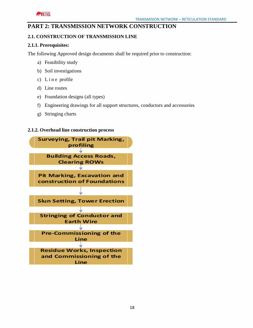
2.1.2. Overhead line construction process
Building Access Roads, Clearing ROWs
Surveying, Trail pit Marking, profiling
Pit Marking, Excavation and construction of Foundations
Slun Setting, Tower Erection
Stringing of Conductor and Earth Wire
Pre-Commissioning of the Line
Residue Works, Inspection and Commissioning of the
Line
Surveying, Trail pit
Stringing of Conductor and Earth Wire
TRANSMISION NETWORK – RETICULATION STANDARD
19
2.1.3. Tower foundation
a) Dimensions, shoring, strutting, dewatering, shuttering, stub setting (or tower footing), backfilling,
assembly and check shall conform to the civil engineering design approved by REG.
b) All 220 kV towers foundations shall be constructed with full concrete; but for 110 kV both
concrete and grillage foundation may be applicable referring to civil engineering design in
accordance with EN 50341-1 and IEC 60826.
c) The following tolerances shall be applicable in case of position of foundation as a whole with
reference to tower position as spotted on the survey chart:
Table 13: Requirements for tower foundation
Type of tower Out of
Alignment From centre of route
From trans centre line
Suspension or intermediate 0.50 ±25mm ±250mm
Section or tension (Set at bi-section of deviation angle)
0.50 ±25mm ±25mm
2.1.4. Tower erection
a) Towers shall be erected according to engineering drawings from manufacturer and the approved
line profile.
b) Towers shall be erected after the concrete is at least 28 days old.
c) Straining of the members shall not be permitted for bringing them into position. Before
starting erection of an upper section, the lower section shall be completely braced and all bolts
fitted in accordance with approved drawings.
d) All plan diagonals relevant to a section of tower shall be placed in position' before assembly of
upper section is taken up.
e) All bolts shall have their nuts facing outside the tower for horizontal or nearly horizontal bolt
connections and downwards for vertical bolt connections. Bolts, nuts and washers shall be of the
same quality and standards as steel tower structure parts.
f) The cross-arm shall be assembled on ground and the top cross-arm shall be lifted first, followed
by the middle and bottom cross-arms. The tips shall be fully tightened before lifting them into
position. Such bolts which are not accessible for tightening by ordinary tommy spanners, may be
tightened with the help of box or ratchet ring spanners.
TRANSMISION NETWORK – RETICULATION STANDARD
20
g) All nuts shall be tightened properly using correct size spanners. Before tightening, it will be
seen that filler washers and plates are placed in relevant gaps between members. Bolts of proper
size and length are inserted, and one spring washer has been inserted under each nut. In case of
step bolts, spring washer shall be placed under the outer nut.
h) The bolts and nuts in all joints up to 5m height above tower base shall be made in such a way to
avoid theft (anti-theft bolt).
i) The following accessories shall be part of the tower: number plate, danger notice plate, helicopter
patrol plate, phase plates, circuit plates, anti-climbing fittings, bird guards and step bolts above anti-
climbing fittings.
j) Except where otherwise specified all ferrous parts shall be galvanized. Galvanizing of the members
and accessories of the tower shall conform to ISO 752 and ISO 10684:2004.
2.1.5. Insulator, accessories and fittings
a) The insulator strings shall be fixed on the towers just prior to the strings of conductors.
b) Damaged or repaired insulators, accessories and fittings shall not be used in installation.
c) Before hoisting, all insulators shall be cleaned in a manner that may not spoil or injure or scratch.
d) Security clips shall be in position for the insulators before hoisting.
e) Arcing horns or guard rings, if required, shall be placed along the line on suspension, and facing
upwards on tension insulator string assemblies, the poke arrangements shall be horizontal for
tension, and longitudinal for suspension strings.
f) All fittings for insulators shall be malleable or cast iron hot-dipped galvanized.
g) Strength of insulators shall be such that the safety factor when the insulators are supporting the
maximum working load is not less than 2.5.
h) All insulator units will be composed of top and bottom arcing rings to equalize the voltage
distribution over the insulator.
2.1.6. Conductor stringing
Conductor stringing shall be carried out using appropriate stringing machines and tools. The maximum
tolerance in final still air sag at maximum temperature shall be ± 4 percent of such sag, in any span as
obtained from the sag tension chart. The sag of any conductor in a span shall not depart from the mean
sag of all conductors in the same span by more than 3 percent.
TRANSMISION NETWORK – RETICULATION STANDARD
21
2.1.6.1. Tensioning and sagging of Conductors
The tension insulator sets, complete with clamped conductors shall be hoisted at the ends remote from
the tensioning points. The running blocks at the tensioning end shall be fitted on the cross -arms with
sacking wrapped under the slings. The mid-span tension joints shall be placed to ensure the following:
a) No joint shall be placed within 15m of the conductor support;
b) There shall be no joints in important crossing span.
c) There shall be not more than one joint per conductor in a span.
d) The tensioning and sagging shall be done in accordance with the approved stringing charts
prepared from the data and relevant specifications of the line. Tensioning and sagging operations
shall be carried out in calm weather when rapid changes in temperature are not likely to occur.
2.1.6.2. Clipping-in
a) Clamping the conductors in position, armoring at supports, placing the dampers and spacers,
etc, shall be done in accordance to the manufacturer instruction manual.
b) The jumpers at the section and angle towers shall be formed to a curved shape to ensure
minimum clearance requirements. Pilot suspension insulator strings with or without dead weights
shall be used where necessary to restrict jumper swing. Fasteners on all fittings and accessories
shall be secured in position; the security clip also properly opened and sprung into position.
c) Repairs to conductors shall be carried out during the running out operations, with either repair
sleeves or jointing sleeves.
2.1.7. Conductor spacing and clearances
The conductor spacing and clearances shall be in accordance to the approved string tension
chart;
2.1.7.1. Live metal-structure clearances
Air gap between earthed tower steelwork and line conductors or live metal string components are as
follows:
a) Net clearance of 2.910 m for insulator or jumper swing, without wind at every day temperature
(25°C).
b) Net clearance of 1.600 m for insulator or jumper swing corresponding to a wind (wind pressure
of 450 Pa) speed of 60% of the maximum wind at every day temperature (25°C).
TRANSMISION NETWORK – RETICULATION STANDARD
22
c) Net clearance of 0.890 m for insulator or jumper swing corresponding to the maximum wind
speed (wind pressure of 760 Pa) at every day temperature (25°C). (Precise Source and
preferably IEC and consider different voltage levels)
2.1.8. Aircraft warning devices
Due to the activity of aircraft in the vicinity of certain parts of the transmission line, it shall be
necessary to mount warning spheres on earth wires at some locations with the following features:
a) Aircraft warning spheres shall be capable of being clamped securely to overhead earth wire.
b) The sphere itself shall be of plastic or fiber glass construction of at least 0.5m in diameter and
colored as required by local regulations.
2.1.9. Towers earthing
a) All high voltage towers shall be permanently and efficiently earthed. Each grounding shall be
constructed in such a way that isolation from the tower and concrete foundation is possible to
allow earthing inspection during line service life.
b) Continuous overhead shield wire (OHSW) shall be provided and securely fastened to each tower
c) All structures shall be provided with means for connecting earthing devices at or around
nominal ground level, on each leg and for connecting earth wire bonds to each top cross-arm
or earth wire peak.
d) Maximum individual earthing resistance of a tower shall be not greater than 10Ω
e) All switchyard equipment shall be earthed with a value not greater than 1Ω.
f) The tower inside the substation or outside the boundary of the substation at a distance less than
100m must be connected to the earthing system of the substation, these towers must be earthed
with a value not greater than 1Ω.
g) All 220kV and 110kV towers located within a distance of 1200m from center point of
substation must be earthed with a value not more than 5Ω.
h) The earthing test shall be carried out before the OHSW connected;
i) The use of chemicals to reduce soil resistivity is prohibited;
j) The earthing tests shall be conducted preferably in dry season.
TRANSMISION NETWORK – RETICULATION STANDARD
23
2.2. CONSTRUCTION OF SUBSTATION
2.2.1. Pre-requisites
The following approved design documents and assessment reports shall be required prior to construction;
a) Feasibility Study
b) Environmental Impact Assessment Report (Oil and SF6 Gas Handling, Erosion & Sediment
Control)
c) Topographic survey report
d) Soil investigation report
e) Substation layout (Civil works and electrical installation)
f) Electrical Equipment drawings and installation guides
g) Operational Health and Safety Implementation plan)
h) Resettlement Action plan
The substation construction works shall be carried out in accordance to the national safety legal
framework, IEC61850, REG Policy & Safety Operating procedures and RS ISO 45001: 2018
Operational Health & Safety. Residue works, inspection and commissioning of line.
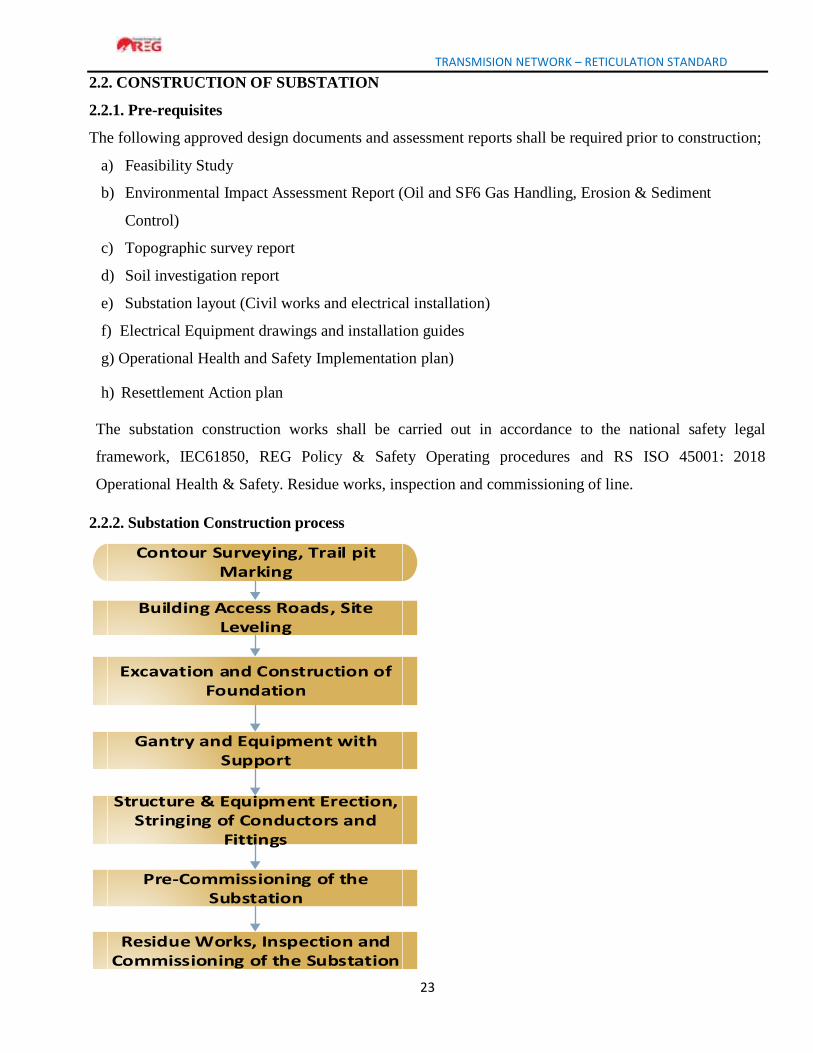
2.2.2. Substation Construction process
Building Access Roads, Site Leveling
Contour Surveying, Trail pit Marking
Excavation and Construction of Foundation
Gantry and Equipment with Support
Structure & Equipment Erection, Stringing of Conductors and
Fittings
Pre-Commissioning of the Substation
Residue Works, Inspection and Commissioning of the Substation

TRANSMISION NETWORK – RETICULATION STANDARD
24
2.2.3. Civil works
All civil works shall be carried out according to the approved drawings and civil materials. The
required drawings shall be the following:
a) Structural drawing (dimensions, weight, etc.);
b) Substation layouts;
c) Equipment arrangement;
d) Foundations of equipment in the outdoor switchyard;
e) Power cable trenches;
f) Protection and control cable trenches;
g) Water drainage inside and outside the substation
h) Access roads to substation equipment
i) Boundary fence and entrance gates
j) Electrical control building
2.2.4. Installation of substation primary equipment
2.2.4.1. Pre-requisite
The following approved design documents shall be required prior to installation:
a) Outdoor Electrical Single Line Diagram
b) Switchyard General Arrangement
c) Equipment test reports
d) Equipment installation and instruction manuals
All substation equipment shall be installed according to approved design documents and specific
equipment installation manuals from manufacturers.
2.2.4.2. Disconnector and Earthing Switches
a) All disconnector and earthing switches shall be installed as indicated on the Switchyard General
Arrangement.
b) All moving parts shall be lubricated for smooth operation.
c) The mechanical and electrical mechanisms shall be interlocked in manner to avoid closing
grounding blades when the main switch is in service
TRANSMISION NETWORK – RETICULATION STANDARD
25
2.2.4.3. Lightning (Surge) Arrestors
a) The lightning Arrestors shall be installed according to IEC-99-4 and to the approved design;
b) The lightning arrestors are installed with discharges number counter;
c) In cases where, surge arrestors are supplied in more than one section, these sections must be
joined together to form one unit before being erected onto the support structure.
2.2.4.4. Voltage Transformer (VT)
a) The V.T. secondary terminals shall be brought out through miniature circuit breakers
(MCB) of suitable rating in a weatherproof terminal complying with IP65.
b) The nameplate indicating all technical characteristics shall be fixed on the accessible level
of the VT. The level of quantity of insulating oil shall be visible and accessible.
2.2.4.5. Current Transformers (CT)
a) The type of construction and insulation shall comply with IEC 60185/ 1966 and IEC 60186/
1969;
b) CT terminal boxes shall be properly sealed to prevent any dust, rain water and insects;
c) All terminals of CT shall be well tightened and unused CT secondary terminals are to be
properly shorted to avoid development of abnormal voltage and subsequent failure of CTs in
case they are left open.
2.2.4.6. Circuit Breaker
The drive mechanism for the three-position switch shall be for both, manual and motor operation.
This motor mechanism shall be commanded with 110 V DC.
2.2.4.7 Bus bar
The bus bar gantries shall be erected as for a double bus bar system.
2.2.4.8 Conductors in switchyard
a) Landing spans (clearance), strung bus-bars and overhead earth wires must be installed in accordance
with the Substation General Arrangement and Section Drawings, plus the relevant Standard Assembly
Drawing(s). The conductors must be strung to the correct sags and/or tensions as specified on the
appropriate drawing.
TRANSMISION NETWORK – RETICULATION STANDARD
26
b) The conductor must not be driven over or walked on by pedestrians. Every precaution must be
taken to ensure that the conductors when erected are left without any scratches, cuts, protruding
strands, bird caging, rough welds, deposits of grease or dirt, deformation or adhesions.
2.2.4.9. Power Transformer
a) The transformer shall wear a plate in accordance with IEC 60076, at an accessible level.
b) The oil level in the conservator shall not be below the level of the H.V. bushing caps.
c) The oil level shall have adequate capacity with highest and lowest visible oil level;
d) The neutral points shall be brought out by suitable means and shall be grounded as per
requirements of the Substation design.
2.2.5. Control Building
The control building to be constructed shall contain all auxiliaries. The scope of civil works shall
comprise but not limited to the following approved specific designs:
a) Foundations of equipment in the outdoor switchyard
b) Boundaries fence and entrance gates
c) Site installations
d) Electrical control room
e) Electrical switchgear rooms: The 30/15 kV switchgear room shall be constructed such as to
have space for at least 2 additional feeders for each bus bar side.
f) Electrical auxiliary rooms ( such a s A C /DC supply, battery, control, relays, SCADA and
telecommunication rooms etc…), offices and utilities
g) Small power and lighting installation including outdoor substation and security lighting
system;
h) Ventilation system;
i) Cable laying between the station building and the outdoor switchyard; MV underground cables
from power transformer to the switchgears shall be copper, single-core with a minimum cross
section of 95mm2 Cu.
j) Earthing grid for the substation
k) Piping for water supply, sanitary works, sewer and rainwater drainage systems and
connections.
TRANSMISION NETWORK – RETICULATION STANDARD
27
l) Safety fence around the outdoor switchyard.
m) Surrounding pavements and gravelling of all areas inside the plot limits/adjacent roads. The
substation contractor is bound to coordinate the electrical and the civil work for achieving an
homogeneous and uniform design. The electrical and civil works shall be approved by the
project manager before execution as per the contract.
n) Firefighting system
2.2.6. Substation earthing
a) The substation earthing system must be constructed and commissioned in accordance to the
approved design as referred to IEEE 80-2000 Guide for Safety in AC Substation Grounding,
ENA EG1-2006 Substation Earthing Guide and IEC standards.
b) Earth grid conductor crimp connections, including lugs must be well compressed.
c) To prevent the transfer of dangerous voltages outside the substation (switchyard), al l
conducting services leaving the earth grid area (metallic pipes, fences, control, protection and
communication cables, MV panel etc.) must be earthed independently.
TRANSMISION NETWORK – RETICULATION STANDARD
28
PART 3: MAINTENANCE OF TRANSMISSION NETWORK
3.1. Pre-requisite
The following approved design documents shall be required to guide in the maintenance activities of
the transmission network:
a) Manufacturer instruction/service manual
b) Commissioning test reports
c) As built drawings
d) Maintenance plan
e) Health & Safety procedure manual
3.2. Maintenance of transmission line
Maintenance works on the transmission lines shall either be carried out on planned/routine basis to
check for the operability of the line or as corrective measures after an inspection or unexpected
failure.
3.2.1. Preventive/ planned maintenance
Planned transmission line inspection shall be carried out at least once in every 6 months. This shall be
carried out in accordance to REG procedure manuals and REG operating safety procedures. An
approved transmission line quality check list Annex 2, should be used and shall include but not limited
to the activities in the standard transmission maintenance program, Table 14.
The transmission line checklist as in Annex 2 shall consist mainly of the
following:
a) Location, tower number, type of tower (angle, suspension);
b) Clearances of the line, to ground and in air, vertical and horizontal;
c) Availability of all tower parts and their conditions;
d) Earthing system;
e) Condition of foundations;
f) Availability and position of arcing horns;
g) Condition of conductors, jumpers, clamps, dampers, etc.
3.2.2. Fault/Curative Maintenance
Fault maintenance shall include intervention activities arising from unexpected in service line
failure/trip. These activities shall be carried out in the shortest time possible as described in REG
procedural manual and Safety operating procedures.
TRANSMISION NETWORK – RETICULATION STANDARD
29
In events, that may require an outage, REG management shall approve it.
An approved transmission line quality checklist Annex 2 should be used and shall include but not
limited to the activities in the standard transmission maintenance program, Table 14.
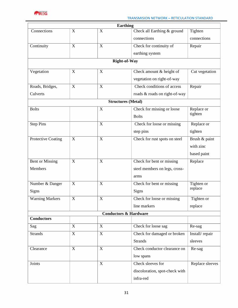
Table 14: Standard Transmission Line Maintenance Program
Transmission Line Maintenance Program
Description Type of Inspection Activities Corrective
Actions
Visual Climbing Visit
Frequency
After 6
Months
2 years
Items to Inspect According to
the Type of Inspection
Identification
Name of
Transmission line
X X Record name of transmission
Line
N/A
Tower Number X X Record number of tower N/A
Type of tower
(Tension or
Suspension)
X X Record type of tower N/A
GPS Coordinate X X Record GPS Coordinate N/A
Footing
Ground Line X Check back filling around
Footings
Improve backfill
Corrosion X X Check for rust or corrosion on footings
Apply zinc based
paint
Diagonal Braces X X Check for damaged or
missing members
Replace missing
members
Concrete X X Eroded or cracked concrete
Footings
Repair or replace
concrete
Anchor Bolts & Nuts X X Check for missing or loose
Bolts
Tighten or replace
bolts or nuts
Depth & Alignment X X Check to see if tower plumb
or if footings have shifted
Re-plumb or reset
tower
TRANSMISION NETWORK – RETICULATION STANDARD
31
Earthing
Connections X X Check all Earthing & ground
connections
Tighten
connections
Continuity X X Check for continuity of
earthing system
Repair
Right-of-Way
Vegetation X X Check amount & height of
vegetation on right-of-way
Cut vegetation
Roads, Bridges,
Culverts
X X Check conditions of access
roads & roads on right-of-way
Repair
Structures (Metal)
Bolts X Check for missing or loose
Bolts
Replace or tighten
Step Pins X Check for loose or missing
step pins
Replace or
tighten
Protective Coating X X Check for rust spots on steel Brush & paint
with zinc
based paint
Bent or Missing
Members
X X Check for bent or missing
steel members on legs, cross-
arms
Replace
Number & Danger
Signs
X X Check for bent or missing
Signs
Tighten or replace
Warning Markers X X Check for loose or missing
line markers
Tighten or
replace
Conductors & Hardware
Conductors
Sag X X Check for loose sag Re-sag
Strands X X Check for damaged or broken
Strands
Install/ repair
sleeves
Clearance X X Check conductor clearance on
low spans
Re-sag
Joints X Check sleeves for
discoloration, spot-check with
infra-red
Replace sleeves
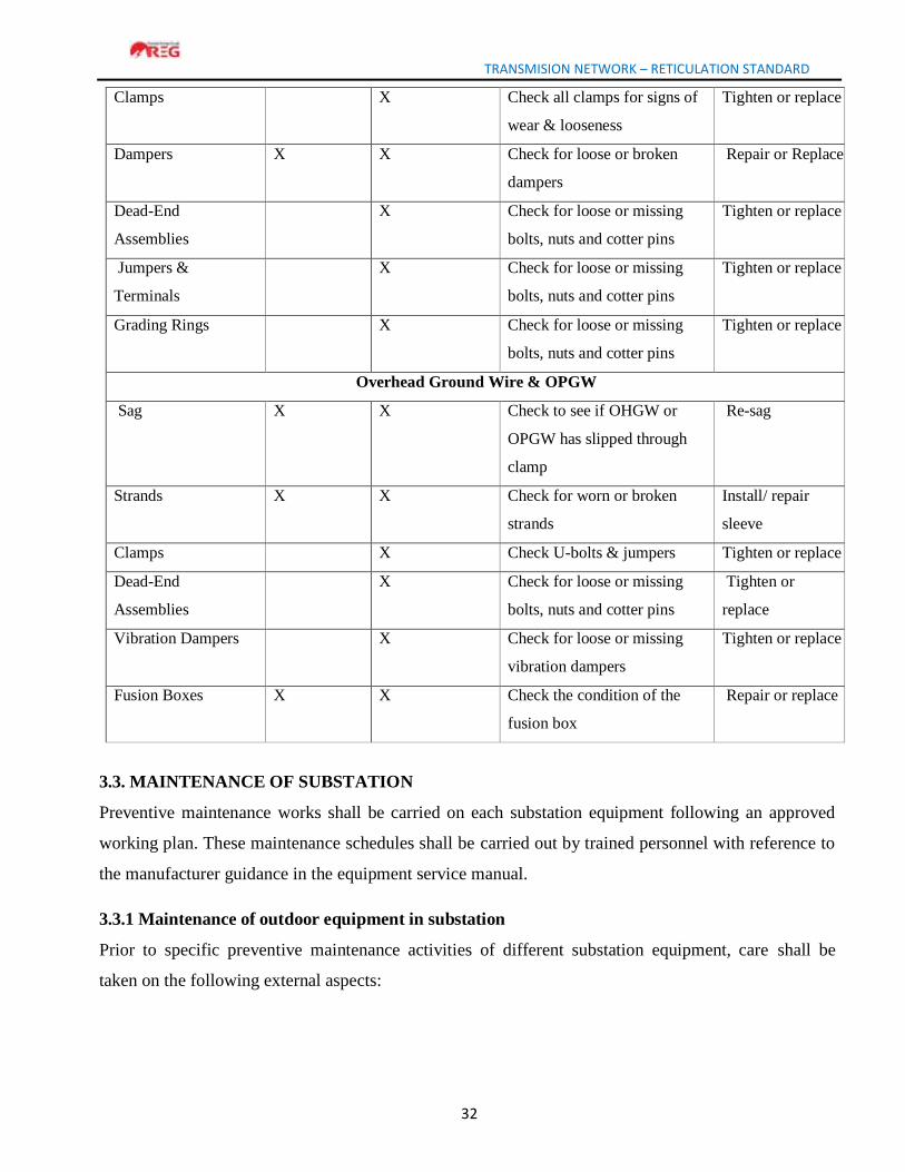
TRANSMISION NETWORK – RETICULATION STANDARD
32
Clamps X Check all clamps for signs of
wear & looseness
Tighten or replace
Dampers X X Check for loose or broken
dampers
Repair or Replace
Dead-End
Assemblies
X Check for loose or missing
bolts, nuts and cotter pins
Tighten or replace
Jumpers &
Terminals
X Check for loose or missing
bolts, nuts and cotter pins
Tighten or replace
Grading Rings X Check for loose or missing
bolts, nuts and cotter pins
Tighten or replace
Overhead Ground Wire & OPGW
Sag X X Check to see if OHGW or
OPGW has slipped through
clamp
Re-sag
Strands X X Check for worn or broken
strands
Install/ repair
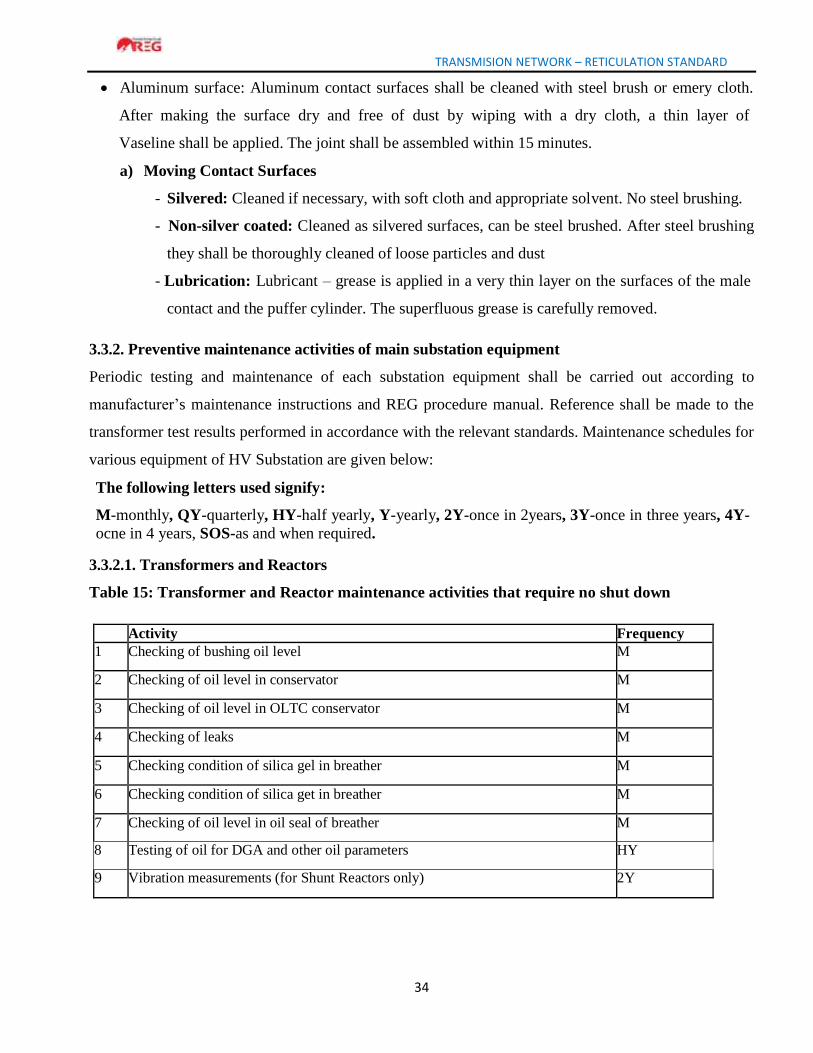
sleeve
Clamps X Check U-bolts & jumpers Tighten or replace
Dead-End
Assemblies
X Check for loose or missing
bolts, nuts and cotter pins
Tighten or
replace
Vibration Dampers X Check for loose or missing
vibration dampers
Tighten or replace
Fusion Boxes X X Check the condition of the
fusion box
Repair or replace
3.3. MAINTENANCE OF SUBSTATION
Preventive maintenance works shall be carried on each substation equipment following an approved
working plan. These maintenance schedules shall be carried out by trained personnel with reference to
the manufacturer guidance in the equipment service manual.
3.3.1 Maintenance of outdoor equipment in substation
Prior to specific preventive maintenance activities of different substation equipment, care shall be
taken on the following external aspects:
TRANSMISION NETWORK – RETICULATION STANDARD
33
3.3.1.1. External Cleaning
The insulators of the transformer bushings; circuit breaker; CT; VT; isolator shall be cleaned from
dirt/dust deposition together with the cleaning of the other insulators in the substation. Frequency of
this cleaning depends on the polluting atmosphere. For installations with higher atmospheric pollution,
cleaning frequency may be increased and these may be suitably protected against pollution.
3.3.1.2. Rust Protection
All steel equipment support and enclosures such as marshalling kiosks, boxes parts of the operating
mechanism are made of steel and are surface treated against rust. In spite of the good rust protection,
minor corrosion will occur after some years, especially when these are standing in strong corrosive
surroundings. The rust stains shall be sand papered away and new rust protection shall be painted or
sprayed on. As rust protection, grease G or Tectyl 506 is recommended.
3.3.1.3. Lubrication
The lubricants recommended by equipment manufacturers shall primarily be used. The bearings of
the breaker and operating mechanism of isolator are to be lubricated with grease (appropriate) although
these normally do not need lubrication before the major overhauls.
Plain bearings in mechanism details such as arms, links and link gears are also to be lubricated with
appropriate grease. These bearings shall be regularly lubricated with a few drops of appropriate oil.
The teeth in the gear shall be lubricated with appropriate grease. Dryness of driving mechanism may lead
to mal- operation and failure.
3.3.1.4. Treatment of Contact Surfaces
The contacts of breaker / isolator / ground switch shall be treated according to the following
instructions: Silvered contact surfaces:
• Silvered contact surfaces shall be cleaned, if necessary, with a soft cloth and appropriate solvent
(Trichloroethane). Steel brushing or grinding is not allowed.
• Copper surface: Copper surfaces shall be clean and oxide free. If necessary, they shall be
cleaned with cloth and solvent or steel brushing. After steel brushing, the surface shall be cleaned
of loose particles and dust.
TRANSMISION NETWORK – RETICULATION STANDARD
34
• Aluminum surface: Aluminum contact surfaces shall be cleaned with steel brush or emery cloth.
After making the surface dry and free of dust by wiping with a dry cloth, a thin layer of
Vaseline shall be applied. The joint shall be assembled within 15 minutes.
a) Moving Contact Surfaces
- Silvered: Cleaned if necessary, with soft cloth and appropriate solvent. No steel brushing.
- Non-silver coated: Cleaned as silvered surfaces, can be steel brushed. After steel brushing
they shall be thoroughly cleaned of loose particles and dust
- Lubrication: Lubricant – grease is applied in a very thin layer on the surfaces of the male
contact and the puffer cylinder. The superfluous grease is carefully removed.
3.3.2. Preventive maintenance activities of main substation equipment
Periodic testing and maintenance of each substation equipment shall be carried out according to
manufacturer’s maintenance instructions and REG procedure manual. Reference shall be made to the
transformer test results performed in accordance with the relevant standards. Maintenance schedules for
various equipment of HV Substation are given below:
The following letters used signify:
M-monthly, QY-quarterly, HY-half yearly, Y-yearly, 2Y-once in 2years, 3Y-once in three years, 4Y-
ocne in 4 years, SOS-as and when required.
3.3.2.1. Transformers and Reactors
Table 15: Transformer and Reactor maintenance activities that require no shut down
Activity Frequency
1 Checking of bushing oil level M
2 Checking of oil level in conservator M
3 Checking of oil level in OLTC conservator M
4 Checking of leaks M
5 Checking condition of silica gel in breather M
6 Checking condition of silica get in breather M
7 Checking of oil level in oil seal of breather M
8 Testing of oil for DGA and other oil parameters HY
9 Vibration measurements (for Shunt Reactors only) 2Y
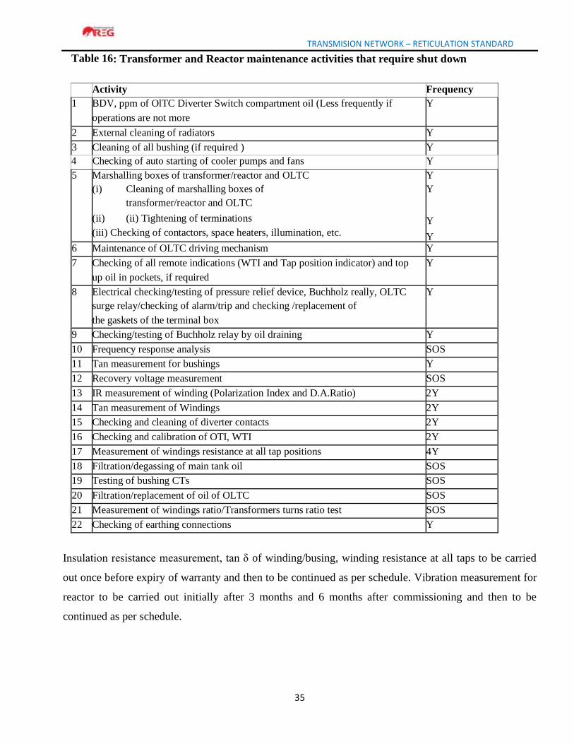
TRANSMISION NETWORK – RETICULATION STANDARD
35
Table 16: Transformer and Reactor maintenance activities that require shut down
Activity Frequency
1 BDV, ppm of OlTC Diverter Switch compartment oil (Less frequently if
operations are not more
Y
2 External cleaning of radiators Y
3 Cleaning of all bushing (if required ) Y
4 Checking of auto starting of cooler pumps and fans Y
5 Marshalling boxes of transformer/reactor and OLTC
(i) Cleaning of marshalling boxes of
transformer/reactor and OLTC
(ii) (ii) Tightening of terminations
(iii) Checking of contactors, space heaters, illumination, etc.
Y
Y
Y
Y 6 Maintenance of OLTC driving mechanism Y
7 Checking of all remote indications (WTI and Tap position indicator) and top
up oil in pockets, if required
Y
8 Electrical checking/testing of pressure relief device, Buchholz really, OLTC
surge relay/checking of alarm/trip and checking /replacement of
the gaskets of the terminal box
Y
9 Checking/testing of Buchholz relay by oil draining Y
10 Frequency response analysis SOS
11 Tan measurement for bushings Y
12 Recovery voltage measurement SOS
13 IR measurement of winding (Polarization Index and D.A.Ratio) 2Y
14 Tan measurement of Windings 2Y
15 Checking and cleaning of diverter contacts 2Y
16 Checking and calibration of OTI, WTI 2Y
17 Measurement of windings resistance at all tap positions 4Y
18 Filtration/degassing of main tank oil SOS
19 Testing of bushing CTs SOS
20 Filtration/replacement of oil of OLTC SOS
21 Measurement of windings ratio/Transformers turns ratio test SOS
22 Checking of earthing connections Y
Insulation resistance measurement, tan δ of winding/busing, winding resistance at all taps to be carried
out once before expiry of warranty and then to be continued as per schedule. Vibration measurement for
reactor to be carried out initially after 3 months and 6 months after commissioning and then to be
continued as per schedule.
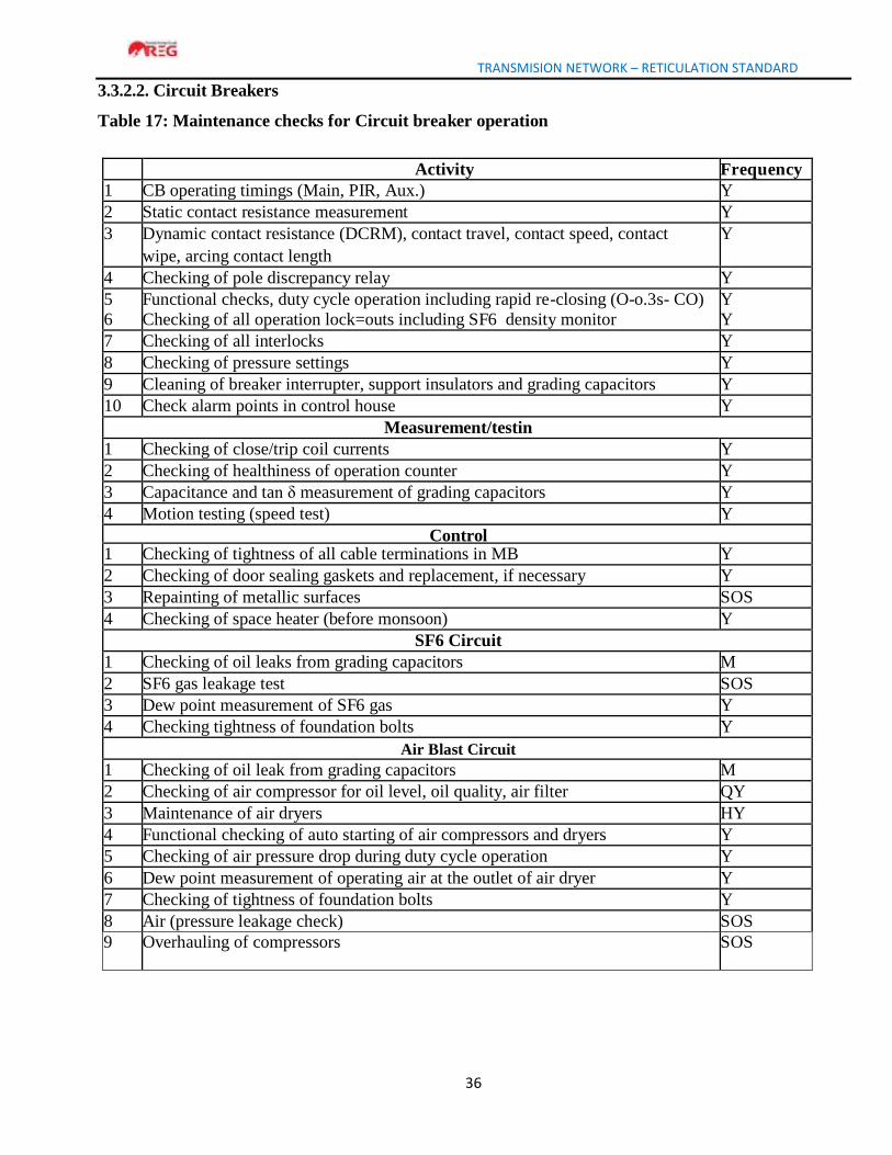
TRANSMISION NETWORK – RETICULATION STANDARD
36
3.3.2.2. Circuit Breakers
Table 17: Maintenance checks for Circuit breaker operation
Activity Frequency
1 CB operating timings (Main, PIR, Aux.) Y
2 Static contact resistance measurement Y
3 Dynamic contact resistance (DCRM), contact travel, contact speed, contact
wipe, arcing contact length
Y
4 Checking of pole discrepancy relay Y
5
6
Functional checks, duty cycle operation including rapid re-closing (O-o.3s- CO)
Checking of all operation lock=outs including SF6 density monitor
Y
Y
7 Checking of all interlocks Y
8 Checking of pressure settings Y
9 Cleaning of breaker interrupter, support insulators and grading capacitors Y
10 Check alarm points in control house Y
Measurement/testin
g 1 Checking of close/trip coil currents Y
2 Checking of healthiness of operation counter Y
3 Capacitance and tan δ measurement of grading capacitors Y
4 Motion testing (speed test) Y
Control
cabinet 1 Checking of tightness of all cable terminations in MB Y
2 Checking of door sealing gaskets and replacement, if necessary Y
3 Repainting of metallic surfaces SOS
4 Checking of space heater (before monsoon) Y
SF6 Circuit
Breakers 1 Checking of oil leaks from grading capacitors M
2 SF6 gas leakage test SOS
3 Dew point measurement of SF6 gas Y
4 Checking tightness of foundation bolts Y
Air Blast Circuit
Breakers 1 Checking of oil leak from grading capacitors M
2 Checking of air compressor for oil level, oil quality, air filter QY
3 Maintenance of air dryers HY
4 Functional checking of auto starting of air compressors and dryers Y
5 Checking of air pressure drop during duty cycle operation Y
6 Dew point measurement of operating air at the outlet of air dryer Y
7 Checking of tightness of foundation bolts Y
8 Air (pressure leakage check) SOS
9 Overhauling of compressors SOS

TRANSMISION NETWORK – RETICULATION STANDARD
37
Minimum Oil Circuit
Breaker 1 Checking of oil leak from grading capacitors M
2 Checking for oil leakage/oil level and N2 pressure (if applicable) M
Testing of oil for BDV After 15 fault trips or yearly 4 Maintenance of breather and change of silica get SOS
Vacuum Circuit
Breakers 1 Cleaning of control cubicle and checking for loose connections QY
2 Checking of ON/OFF indicators, spring charge indicator and checking HY
manual and electrical operation
3 Checking vacuum of interrupter by application of high voltage by
Y
disengaging with operating mechanism
4 Checking erosion of contacts by erosion mark on operating rod or
Y
5 measurement of gap specified n closed position of contacts (wherever
provide)
6 Checking tightness of foundation bolts Y
7 Replacement of vacuum interrupter SOS
Hydraulic Operating
Mechanism 1 Checking of oil level and replenishment/topping up, if necessary M
2 Checking of oil leaks M
3 Checking of oil pressure drop during duty cycle operation check Y
4 Checking of auto-starting/stopping of oil pump, pressure switch settings, etc.
Y
5 Checking of healthiness of accumulator by checking the pressure when building up pressure from zero - Charging
Y
6 Checking of operation of safety value Y
Pneumatic Operating Mechanism
1 Checking of air compressor for oil level, oil quality, air filter, V-belt tension
QY
2 Maintenance of air dryer, if provided HY
3 Functional checking of auto-starting of air compressors and dryers Y
4 Checking of air pressure drop during duty cycle operation Y
5 Overhauling of compressors SOS
Spring Operated
1Mechanism 1 Oil leakages from close and open dashpots, replace the same if observed
Y
2 Greasing/lubrication of gears and various latches in the operating mechanism
Y
3 Checking of play of gaps in catch gears Y
4 Maintenance of spring charging motors, cleaning of carbon brushes
contactors
contactors
and
Y
5 Replacement of oil in dashpot SOS
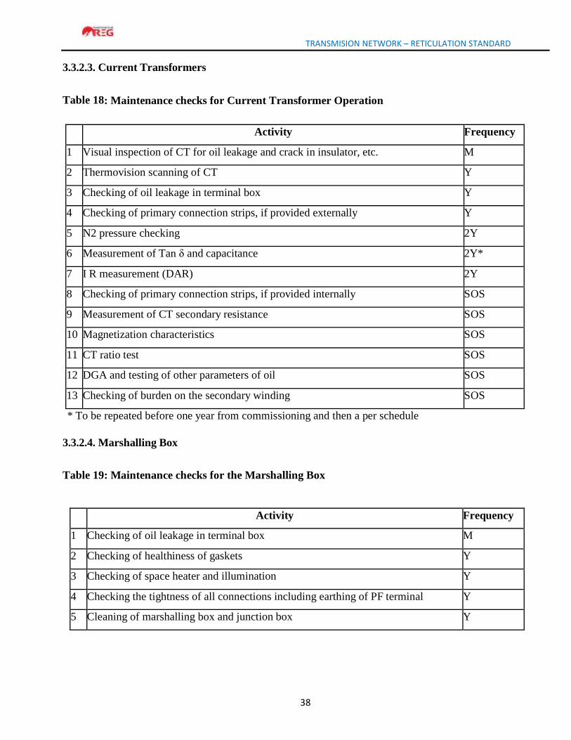
TRANSMISION NETWORK – RETICULATION STANDARD
38
3.3.2.3. Current Transformers
Table 18: Maintenance checks for Current Transformer Operation
Activity Frequency
1 Visual inspection of CT for oil leakage and crack in insulator, etc. M
2 Thermovision scanning of CT Y
3 Checking of oil leakage in terminal box Y
4 Checking of primary connection strips, if provided externally Y
5 N2 pressure checking 2Y
6 Measurement of Tan δ and capacitance 2Y*
7 I R measurement (DAR) 2Y
8 Checking of primary connection strips, if provided internally SOS
9 Measurement of CT secondary resistance SOS
10 Magnetization characteristics SOS
11 CT ratio test SOS
12 DGA and testing of other parameters of oil SOS
13 Checking of burden on the secondary winding SOS
* To be repeated before one year from commissioning and then a per schedule
3.3.2.4. Marshalling Box
Table 19: Maintenance checks for the Marshalling Box
Activity Frequency
1 Checking of oil leakage in terminal box M
2 Checking of healthiness of gaskets Y
3 Checking of space heater and illumination Y
4 Checking the tightness of all connections including earthing of PF terminal Y
5 Cleaning of marshalling box and junction box Y
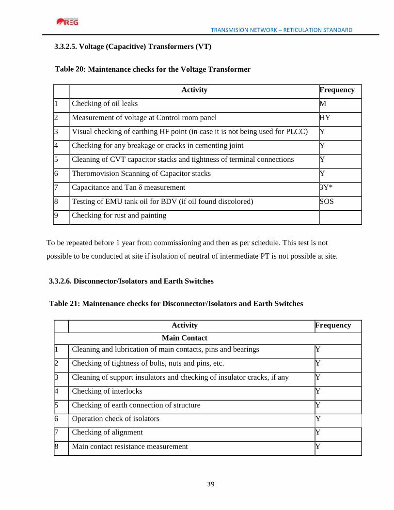
TRANSMISION NETWORK – RETICULATION STANDARD
39
3.3.2.5. Voltage (Capacitive) Transformers (VT)
Table 20: Maintenance checks for the Voltage Transformer
Activity Frequency
1 Checking of oil leaks M
2 Measurement of voltage at Control room panel HY
3 Visual checking of earthing HF point (in case it is not being used for PLCC) Y
4 Checking for any breakage or cracks in cementing joint Y
5 Cleaning of CVT capacitor stacks and tightness of terminal connections Y
6 Theromovision Scanning of Capacitor stacks Y
7 Capacitance and Tan δ measurement 3Y*
8 Testing of EMU tank oil for BDV (if oil found discolored) SOS
9 Checking for rust and painting
To be repeated before 1 year from commissioning and then as per schedule. This test is not
possible to be conducted at site if isolation of neutral of intermediate PT is not possible at site.
3.3.2.6. Disconnector/Isolators and Earth Switches
Table 21: Maintenance checks for Disconnector/Isolators and Earth Switches
Activity Frequency
Main Contact
1 Cleaning and lubrication of main contacts, pins and bearings Y
2 Checking of tightness of bolts, nuts and pins, etc. Y
3 Cleaning of support insulators and checking of insulator cracks, if any Y
4 Checking of interlocks Y
5 Checking of earth connection of structure Y
6 Operation check of isolators Y
7 Checking of alignment Y
8 Main contact resistance measurement Y
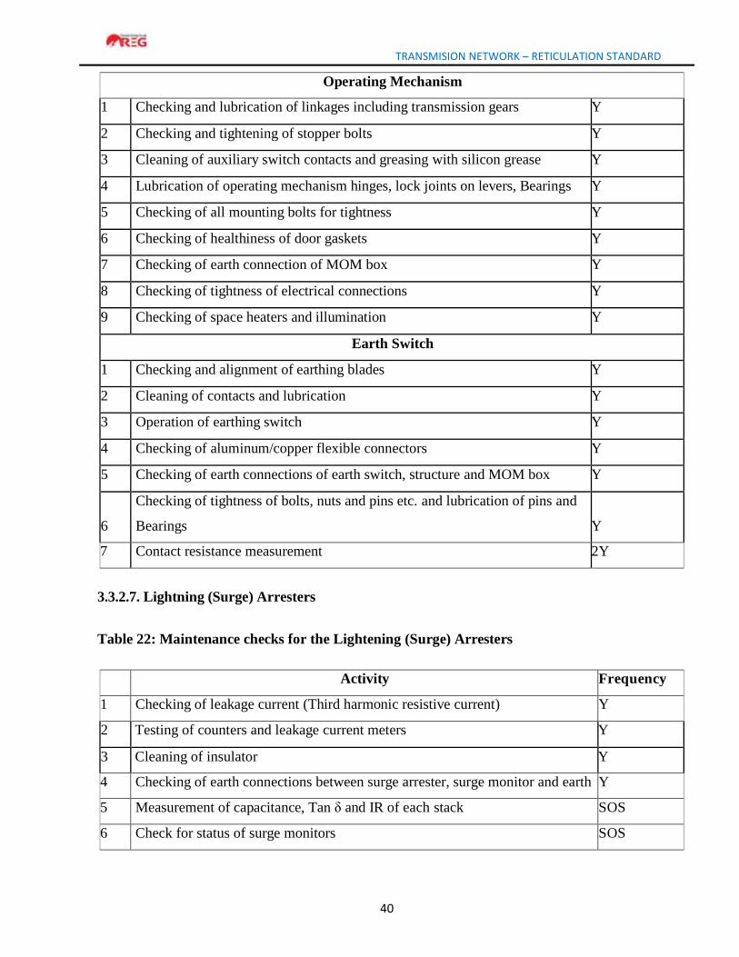
TRANSMISION NETWORK – RETICULATION STANDARD
40
Operating Mechanism
1 Checking and lubrication of linkages including transmission gears Y
2 Checking and tightening of stopper bolts Y
3 Cleaning of auxiliary switch contacts and greasing with silicon grease Y
4 Lubrication of operating mechanism hinges, lock joints on levers, Bearings Y
5 Checking of all mounting bolts for tightness Y
6 Checking of healthiness of door gaskets Y
7 Checking of earth connection of MOM box Y
8 Checking of tightness of electrical connections Y
9 Checking of space heaters and illumination Y
Earth Switch
1 Checking and alignment of earthing blades Y
2 Cleaning of contacts and lubrication Y
3 Operation of earthing switch Y
4 Checking of aluminum/copper flexible connectors Y
5 Checking of earth connections of earth switch, structure and MOM box Y
6
Checking of tightness of bolts, nuts and pins etc. and lubrication of pins and
Bearings
Y
7 Contact resistance measurement 2Y
3.3.2.7. Lightning (Surge) Arresters
Table 22: Maintenance checks for the Lightening (Surge) Arresters
Activity Frequency
1 Checking of leakage current (Third harmonic resistive current) Y
2 Testing of counters and leakage current meters Y
3 Cleaning of insulator Y
4 Checking of earth connections between surge arrester, surge monitor and earth Y
5 Measurement of capacitance, Tan δ and IR of each stack SOS
6 Check for status of surge monitors SOS
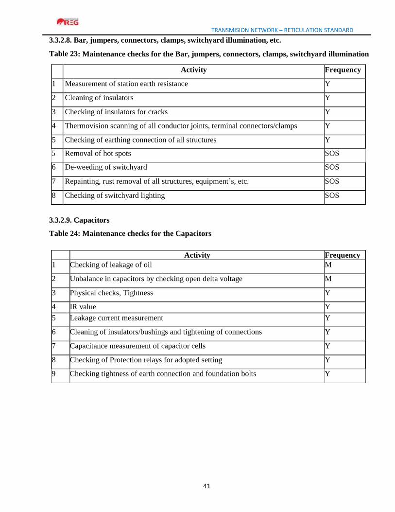
TRANSMISION NETWORK – RETICULATION STANDARD
41
3.3.2.8. Bar, jumpers, connectors, clamps, switchyard illumination, etc.
Table 23: Maintenance checks for the Bar, jumpers, connectors, clamps, switchyard illumination
Activity Frequency
1 Measurement of station earth resistance Y
2 Cleaning of insulators Y
3 Checking of insulators for cracks Y
4 Thermovision scanning of all conductor joints, terminal connectors/clamps Y
5 Checking of earthing connection of all structures Y
5 Removal of hot spots SOS
6 De-weeding of switchyard SOS
7 Repainting, rust removal of all structures, equipment’s, etc. SOS
8 Checking of switchyard lighting SOS
3.3.2.9. Capacitors
Table 24: Maintenance checks for the Capacitors
Activity Frequency
1 Checking of leakage of oil M
2 Unbalance in capacitors by checking open delta voltage M
3 Physical checks, Tightness Y
4 IR value Y
5 Leakage current measurement Y
6 Cleaning of insulators/bushings and tightening of connections Y
7 Capacitance measurement of capacitor cells Y
8 Checking of Protection relays for adopted setting Y
9 Checking tightness of earth connection and foundation bolts Y
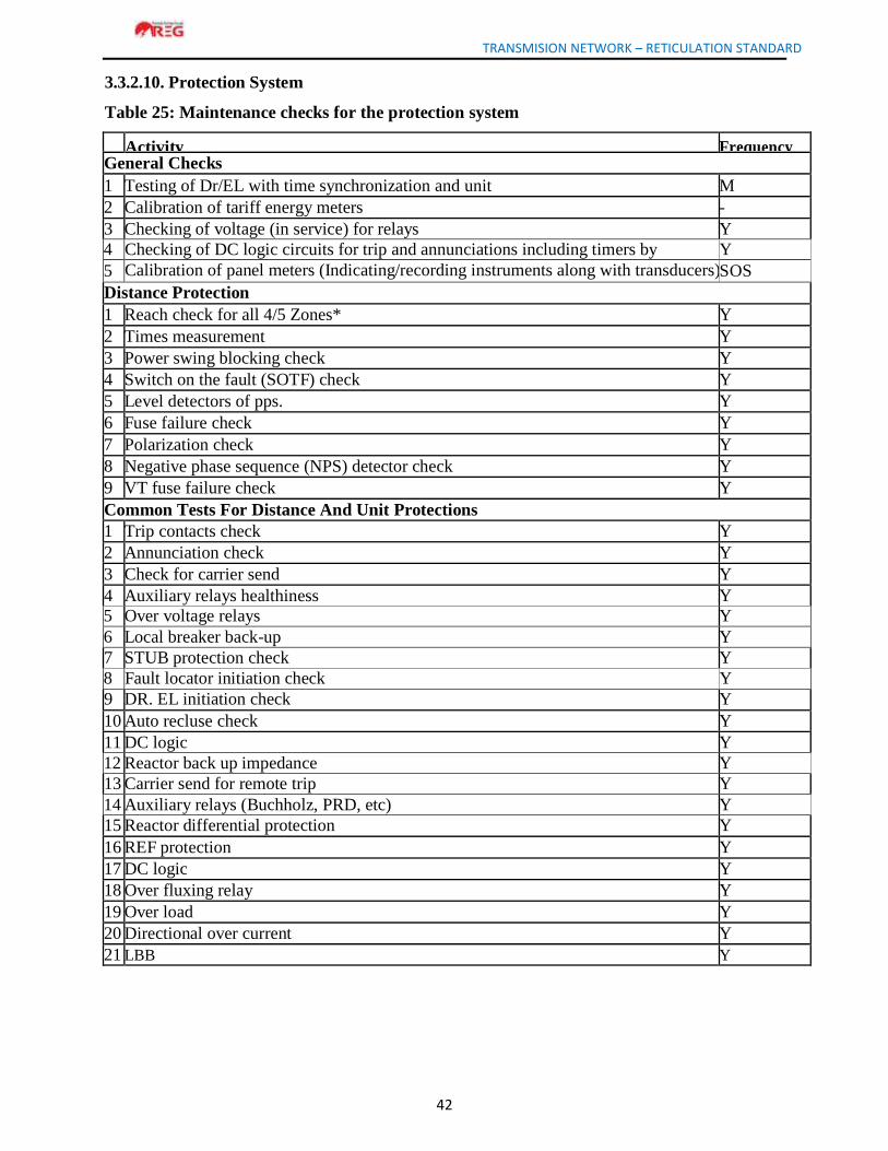
TRANSMISION NETWORK – RETICULATION STANDARD
42
3.3.2.10. Protection System
Table 25: Maintenance checks for the protection system
Activity Frequency General Checks
1 Testing of Dr/EL with time synchronization and unit M
2 Calibration of tariff energy meters -
3 Checking of voltage (in service) for relays Y
4 Checking of DC logic circuits for trip and annunciations including timers by simulation
Y
5 Calibration of panel meters (Indicating/recording instruments along with transducers) SOS
Distance Protection
1 Reach check for all 4/5 Zones* Y
2 Times measurement Y
3 Power swing blocking check Y
4 Switch on the fault (SOTF) check Y
5 Level detectors of pps. Y
6 Fuse failure check Y
7 Polarization check Y
8 Negative phase sequence (NPS) detector check Y
9 VT fuse failure check Y
Common Tests For Distance And Unit Protections
1 Trip contacts check Y
2 Annunciation check Y
3 Check for carrier send Y
4 Auxiliary relays healthiness Y
5 Over voltage relays Y
6 Local breaker back-up Y
7 STUB protection check Y
8 Fault locator initiation check Y
9 DR. EL initiation check Y
10 Auto recluse check Y
11 DC logic Y
12 Reactor back up impedance Y
13 Carrier send for remote trip Y
14 Auxiliary relays (Buchholz, PRD, etc) Y
15 Reactor differential protection Y
16 REF protection Y
17 DC logic Y
18 Over fluxing relay Y
19 Over load Y
20 Directional over current Y
21 LBB
Y
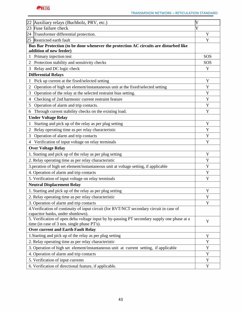
TRANSMISION NETWORK – RETICULATION STANDARD
43
22 Auxiliary relays (Buchholz, PRV, etc.) Y
23 Fuse failure check Y
24 Transformer differential protection. Y
25 Restricted earth fault Y
Bus Bar Protection (to be done whenever the protection AC circuits are disturbed like
addition of new feeder)
1 Primary injection test SOS
2 Protection stability and sensitivity checks SOS
3 Relay and DC logic check Y
Differential Relays
1 Pick up current at the fixed/selected setting Y
2 Operation of high set element/instantaneous unit at the fixed/selected setting Y
3 Operation of the relay at the selected restraint bias setting. Y
4 Checking of 2nd harmonic current restraint feature Y
5 Operation of alarm and trip contacts. Y
6 Through current stability checks on the existing load. Y
Under Voltage Relay
1 Starting and pick up of the relay as per plug setting Y
2 Relay operating time as per relay characteristic Y
3 Operation of alarm and trip contacts Y
4 Verification of input voltage on relay terminals Y
Over Voltage Relay
1. Starting and pick up of the relay as per plug setting Y
2. Relay operating time as per relay characteristic Y
3.peration of high set element/instantaneous unit at voltage setting, if applicable Y
4. Operation of alarm and trip contacts Y
5. Verification of input voltage on relay terminals Y
Neutral Displacement Relay
1. Starting and pick up of the relay as per plug setting Y
2. Relay operating time as per relay characteristic Y
3. Operation of alarm and trip contacts Y
4.Verification of continuity of input circuit (for RVT/NCT secondary circuit in case of
capacitor banks, under shutdown).
5. Verification of open delta voltage input by by-passing PT secondary supply one phase at a
time (in case of 3 nos. single phase PT's). Y
Over current and Earth Fault Relay
1.Starting and pick up of the relay as per plug setting Y
2. Relay operating time as per relay characteristic Y
3. Operation of high set element/instantaneous unit at current setting, if applicable Y
4. Operation of alarm and trip contacts Y
5. Verification of input currents Y
6. Verification of directional feature, if applicable. Y
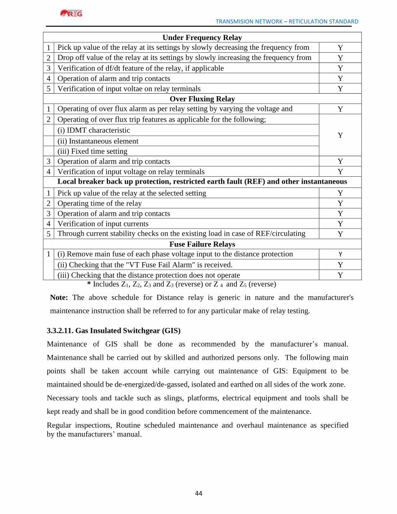
TRANSMISION NETWORK – RETICULATION STANDARD
44
Under Frequency Relay
1 Pick up value of the relay at its settings by slowly decreasing the frequency from
50 Hz Y
2 Drop off value of the relay at its settings by slowly increasing the frequency from
pick up value Y
3 Verification of df/dt feature of the relay, if applicable Y
4 Operation of alarm and trip contacts Y
5 Verification of input voltae on relay terminals Y
Over Fluxing Relay
1 Operating of over flux alarm as per relay setting by varying the voltage and
frequency one at a time Y
2 Operating of over flux trip features as applicable for the following;
Y (i) IDMT characteristic
(ii) Instantaneous element
(iii) Fixed time setting
3 Operation of alarm and trip contacts Y
4 Verification of input voltage on relay terminals Y
Local breaker back up protection, restricted earth fault (REF) and other instantaneous
current operated relays 1 Pick up value of the relay at the selected setting Y
2 Operating time of the relay Y
3 Operation of alarm and trip contacts Y
4 Verification of input currents Y
5 Through current stability checks on the existing load in case of REF/circulating
current differential protection. Y
Fuse Failure Relays
1 (i) Remove main fuse of each phase voltage input to the distance protection
scheme one by one in the relay panel
Y
(ii) Checking that the "VT Fuse Fail Alarm" is received. Y
(iii) Checking that the distance protection does not operate Y
* Includes Z1, Z2, Z3 and Z3 (reverse) or Z 4 and Z5 (reverse)
Note: The above schedule for Distance relay is generic in nature and the manufacturer's
maintenance instruction shall be referred to for any particular make of relay testing.
3.3.2.11. Gas Insulated Switchgear (GIS)
Maintenance of GIS shall be done as recommended by the manufacturer’s manual.
Maintenance shall be carried out by skilled and authorized persons only. The following main
points shall be taken account while carrying out maintenance of GIS: Equipment to be
maintained should be de-energized/de-gassed, isolated and earthed on all sides of the work zone.
Necessary tools and tackle such as slings, platforms, electrical equipment and tools shall be
kept ready and shall be in good condition before commencement of the maintenance.
Regular inspections, Routine scheduled maintenance and overhaul maintenance as specified
by the manufacturers’ manual.
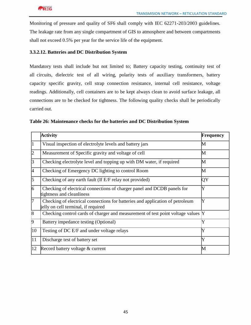
TRANSMISION NETWORK – RETICULATION STANDARD
45
Monitoring of pressure and quality of SF6 shall comply with IEC 62271-203/2003 guidelines.
The leakage rate from any single compartment of GIS to atmosphere and between compartments
shall not exceed 0.5% per year for the service life of the equipment.
3.3.2.12. Batteries and DC Distribution System
Mandatory tests shall include but not limited to; Battery capacity testing, continuity test of
all circuits, dielectric test of all wiring, polarity tests of auxiliary transformers, battery
capacity specific gravity, cell strap connection resistance, internal cell resistance, voltage
readings. Additionally, cell containers are to be kept always clean to avoid surface leakage, all
connections are to be checked for tightness. The following quality checks shall be periodically
carried out.
Table 26: Maintenance checks for the batteries and DC Distribution System
Activity Frequency
1 Visual inspection of electrolyte levels and battery jars M
2 Measurement of Specific gravity and voltage of cell M
3 Checking electrolyte level and topping up with DM water, if required M
4 Checking of Emergency DC lighting to control Room M
5 Checking of any earth fault (If E/F relay not provided) QY
6 Checking of electrical connections of charger panel and DCDB panels for tightness and cleanliness
Y
7 Checking of electrical connections for batteries and application of petroleum
jelly on cell terminal, if required
Y
8 Checking control cards of charger and measurement of test point voltage values Y
9 Battery impedance testing (Optional) Y
10 Testing of DC E/F and under voltage relays Y
11 Discharge test of battery set Y
12 Record battery voltage & current M
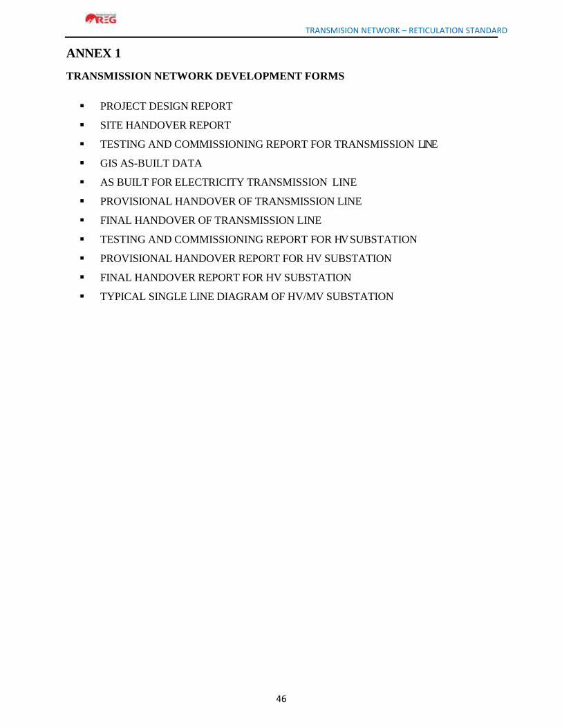
TRANSMISION NETWORK – RETICULATION STANDARD
46
ANNEX 1
TRANSMISSION NETWORK DEVELOPMENT FORMS
PROJECT DESIGN REPORT
SITE HANDOVER REPORT
TESTING AND COMMISSIONING REPORT FOR TRANSMISSION LINE
GIS AS-BUILT DATA
AS BUILT FOR ELECTRICITY TRANSMISSION LINE
PROVISIONAL HANDOVER OF TRANSMISSION LINE
FINAL HANDOVER OF TRANSMISSION LINE
TESTING AND COMMISSIONING REPORT FOR HV SUBSTATION
PROVISIONAL HANDOVER REPORT FOR HV SUBSTATION
FINAL HANDOVER REPORT FOR HV SUBSTATION
TYPICAL SINGLE LINE DIAGRAM OF HV/MV SUBSTATION
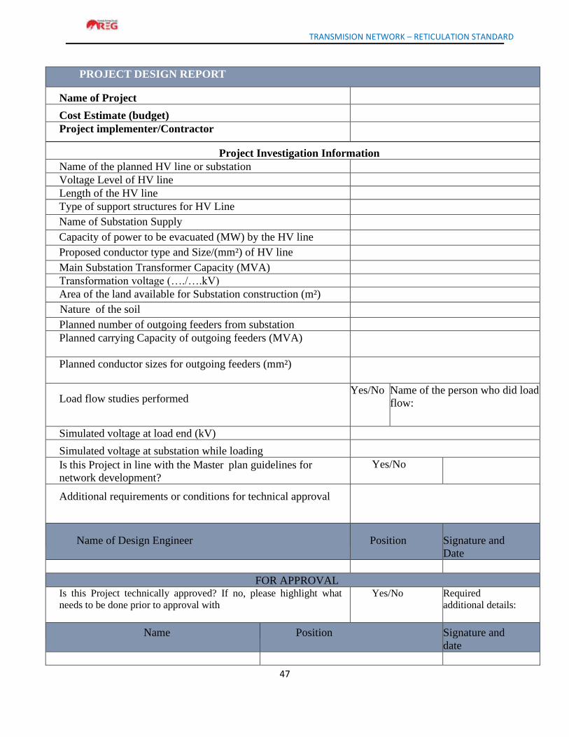
TRANSMISION NETWORK – RETICULATION STANDARD
47
PROJECT DESIGN REPORT
Name of Project
Cost Estimate (budget)
Project implementer/Contractor
Project Investigation Information
Name of the planned HV line or substation
Voltage Level of HV line
Length of the HV line
Type of support structures for HV Line
Name of Substation Supply
Capacity of power to be evacuated (MW) by the HV line
Proposed conductor type and Size/(mm²) of HV line
Main Substation Transformer Capacity (MVA)
Transformation voltage (…./….kV)
Area of the land available for Substation construction (m²)
Nature of the soil
Planned number of outgoing feeders from substation
Planned carrying Capacity of outgoing feeders (MVA)
Planned conductor sizes for outgoing feeders (mm²)
Load flow studies performed
Yes/No Name of the person who did load
flow:
Simulated voltage at load end (kV)
Simulated voltage at substation while loading
Is this Project in line with the Master plan guidelines for
network development?
Yes/No
Additional requirements or conditions for technical approval
Name of Design Engineer Position Signature and
Date
FOR APPROVAL Is this Project technically approved? If no, please highlight what
needs to be done prior to approval with
Yes/No Required
additional details:
Name Position Signature and
date
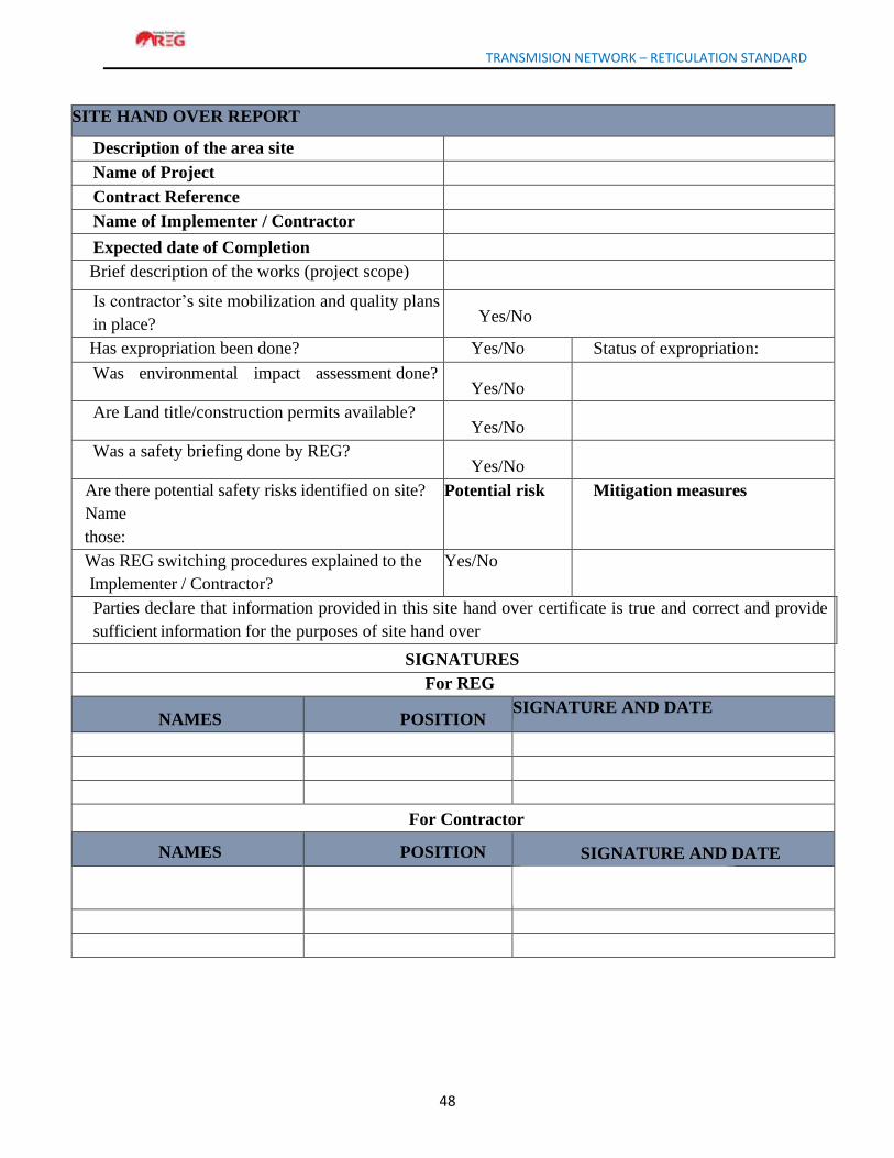
TRANSMISION NETWORK – RETICULATION STANDARD
48
SITE HAND OVER REPORT
Description of the area site
Name of Project
Contract Reference
Name of Implementer / Contractor
Expected date of Completion
Brief description of the works (project scope)
Is contractor’s site mobilization and quality plans
in place? Yes/No
Has expropriation been done? Yes/No Status of expropriation:
Was environmental impact assessment done? Yes/No
Are Land title/construction permits available? Yes/No
Was a safety briefing done by REG? Yes/No
Are there potential safety risks identified on site?
Name
those:
Potential risk Mitigation measures
Was REG switching procedures explained to the
Implementer / Contractor?
Yes/No
Parties declare that information provided in this site hand over certificate is true and correct and provide
sufficient information for the purposes of site hand over
SIGNATURES
For REG
NAMES POSITION SIGNATURE AND DATE
For Contractor
NAMES POSITION SIGNATURE AND DATE
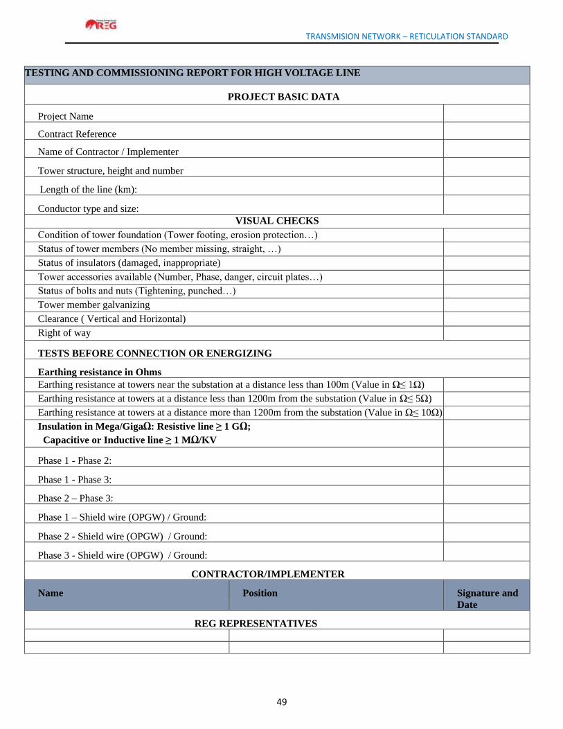
TRANSMISION NETWORK – RETICULATION STANDARD
49
TESTING AND COMMISSIONING REPORT FOR HIGH VOLTAGE LINE
PROJECT BASIC DATA
Project Name
Contract Reference
Name of Contractor / Implementer
Tower structure, height and number
Length of the line (km):
Conductor type and size:
VISUAL CHECKS
Condition of tower foundation (Tower footing, erosion protection…)
Status of tower members (No member missing, straight, …)
Status of insulators (damaged, inappropriate)
Tower accessories available (Number, Phase, danger, circuit plates…)
Status of bolts and nuts (Tightening, punched…)
Tower member galvanizing
Clearance ( Vertical and Horizontal)
Right of way
TESTS BEFORE CONNECTION OR ENERGIZING
Earthing resistance in Ohms
Earthing resistance at towers near the substation at a distance less than 100m (Value in Ω≤ 1Ω)
Earthing resistance at towers at a distance less than 1200m from the substation (Value in Ω≤ 5Ω)
Earthing resistance at towers at a distance more than 1200m from the substation (Value in Ω≤ 10Ω)
Insulation in Mega/GigaΩ: Resistive line ≥ 1 GΩ;
Capacitive or Inductive line ≥ 1 MΩ/KV
Phase 1 - Phase 2:
Phase 1 - Phase 3:
Phase 2 – Phase 3:
Phase 1 – Shield wire (OPGW) / Ground:
Phase 2 - Shield wire (OPGW) / Ground:
Phase 3 - Shield wire (OPGW) / Ground:
CONTRACTOR/IMPLEMENTER
Name Position Signature and
Date
REG REPRESENTATIVES
TRANSMISION NETWORK – RETICULATION STANDARD
50
GIS AS-BUILT DATA
To keep the REG GIS Database update, all Contractors and all Departments who touch on the Network
must submit as-built data after completion of project in addition to all other required documents. These
data should be reported to the Unit in charge of Geographical Information System (GIS). The
following projection should be respected as it is the one used in the REG ArcGIS system:
Coordinate system: GCS_ITRF_2005 or GCS WGS 1984 (as indicated in the contract)
Projection: Transverse Mercator
Datum: D_ITRF_2005 or WGS 1984 (as indicated in the contract)
False Easting: 500,000.0000
False Northing: 5,000,000.0000
Central Meridian: 30.0000
Scale Factor: 0.9999
Latitude of origin: 0.0000
Units: Meter
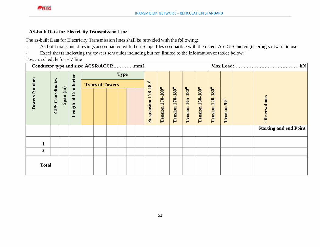
TRANSMISION NETWORK – RETICULATION STANDARD
51
AS-built Data for Electricity Transmission Line
The as-built Data for Electricity Transmission lines shall be provided with the following:
- As-built maps and drawings accompanied with their Shape files compatible with the recent Arc GIS and engineering software in use
- Excel sheets indicating the towers schedules including but not limited to the information of tables below:
Towers schedule for HV line
Conductor type and size: ACSR/ACCR………….mm2 Max Load: ………………………………… kN
Tow
ers
Nu
mb
er
GP
S C
oord
inate
s
Sp
an
(m
)
Len
gth
of
Con
du
ctor Type
Su
spen
sion
178
-180
0
Ten
sion
170
-180
0
Ten
sion
170
-180
0
Ten
sion
165
-180
0
Ten
sion
150
-180
0
Ten
sion
120
-180
0
Ten
sion
90
0
Ob
serv
ati
on
s
Types of Towers
Starting and end Point
1
2
Total
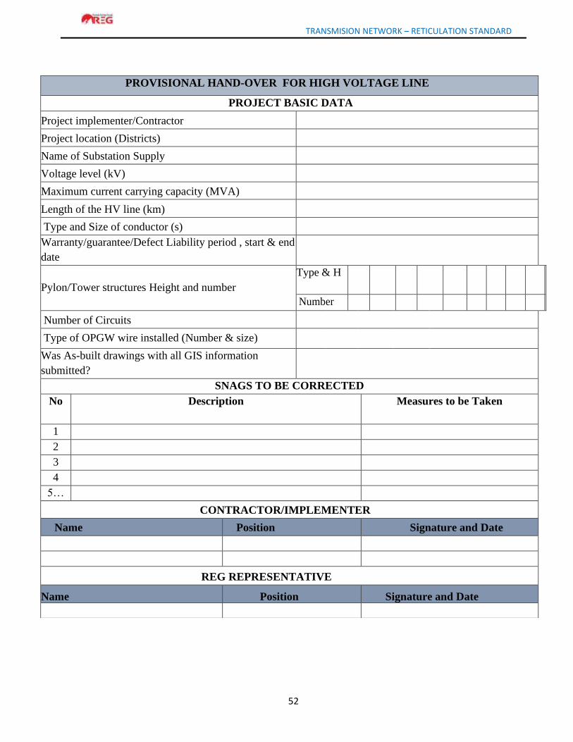
TRANSMISION NETWORK – RETICULATION STANDARD
52
PROVISIONAL HAND-OVER FOR HIGH VOLTAGE LINE
PROJECT BASIC DATA
Project implementer/Contractor
Project location (Districts)
Name of Substation Supply
Voltage level (kV)
Maximum current carrying capacity (MVA)
Length of the HV line (km)
Type and Size of conductor (s)
Warranty/guarantee/Defect Liability period , start & end
date
Pylon/Tower structures Height and number
Type & H
Number
Number of Circuits
Type of OPGW wire installed (Number & size)
Was As-built drawings with all GIS information
submitted?
SNAGS TO BE CORRECTED
No Description Measures to be Taken
1
2
3
4
5…
CONTRACTOR/IMPLEMENTER
Name Position Signature and Date
REG REPRESENTATIVE
Name Position Signature and Date
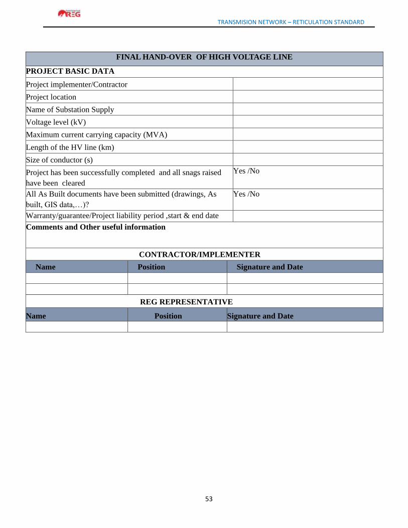
TRANSMISION NETWORK – RETICULATION STANDARD
53
FINAL HAND-OVER OF HIGH VOLTAGE LINE
PROJECT BASIC DATA
Project implementer/Contractor
Project location
Name of Substation Supply
Voltage level (kV)
Maximum current carrying capacity (MVA)
Length of the HV line (km)
Size of conductor (s)
Project has been successfully completed and all snags raised
have been cleared
Yes /No
All As Built documents have been submitted (drawings, As
built, GIS data,…)?
Yes /No
Warranty/guarantee/Project liability period ,start & end date
Comments and Other useful information
CONTRACTOR/IMPLEMENTER
Name Position Signature and Date
REG REPRESENTATIVE
Name Position Signature and Date
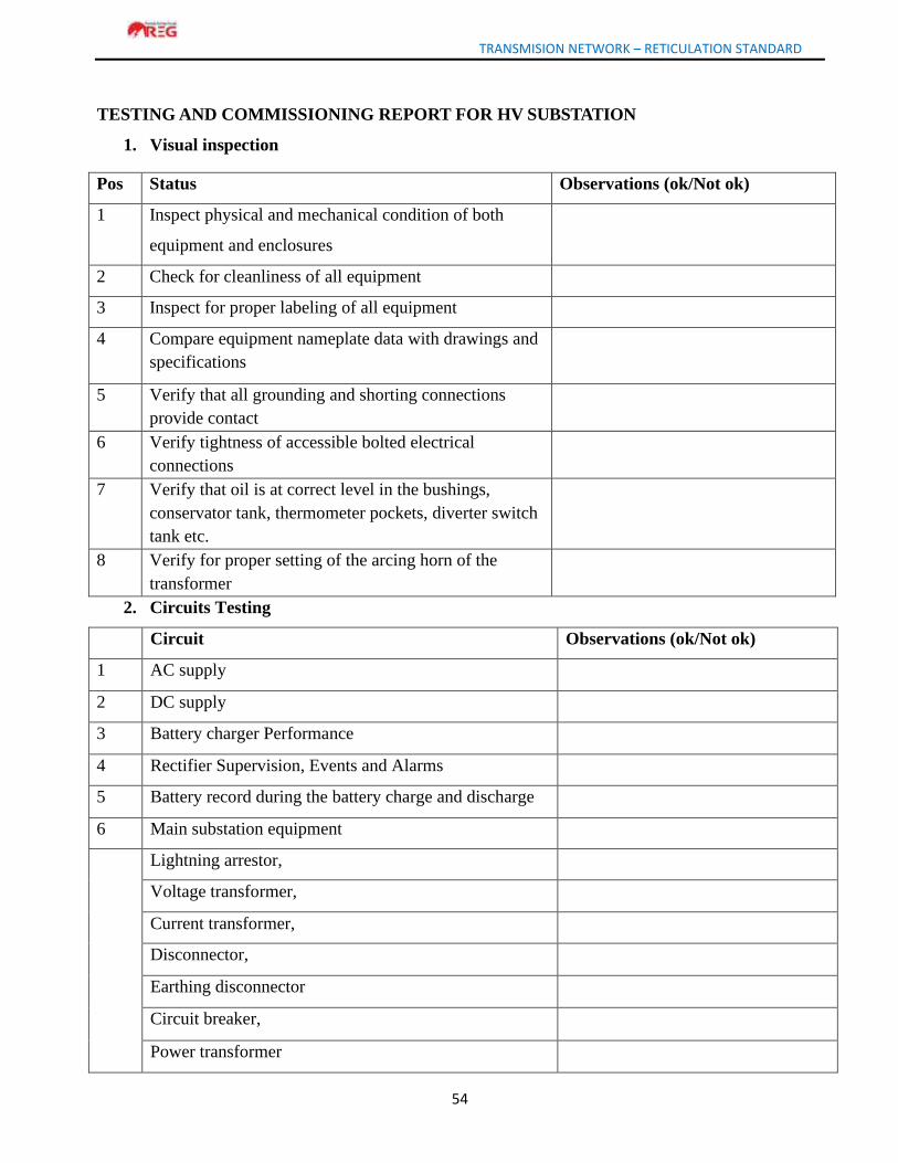
TRANSMISION NETWORK – RETICULATION STANDARD
54
TESTING AND COMMISSIONING REPORT FOR HV SUBSTATION
1. Visual inspection
Pos Status Observations (ok/Not ok)
1 Inspect physical and mechanical condition of both
equipment and enclosures
2 Check for cleanliness of all equipment
3 Inspect for proper labeling of all equipment
4 Compare equipment nameplate data with drawings and
specifications
5 Verify that all grounding and shorting connections
provide contact
6 Verify tightness of accessible bolted electrical
connections
7 Verify that oil is at correct level in the bushings,
conservator tank, thermometer pockets, diverter switch
tank etc.
8 Verify for proper setting of the arcing horn of the
transformer
2. Circuits Testing
Circuit Observations (ok/Not ok)
1 AC supply
2 DC supply
3 Battery charger Performance
4 Rectifier Supervision, Events and Alarms
5 Battery record during the battery charge and discharge
6 Main substation equipment
Lightning arrestor,
Voltage transformer,
Current transformer,
Disconnector,
Earthing disconnector
Circuit breaker,
Power transformer
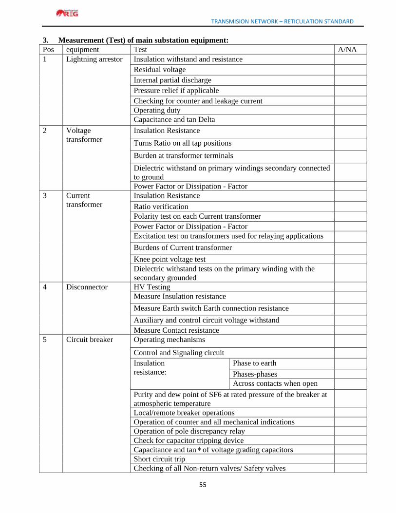
TRANSMISION NETWORK – RETICULATION STANDARD
55
3. Measurement (Test) of main substation equipment:
Pos equipment Test A/NA
1 Lightning arrestor Insulation withstand and resistance
Residual voltage
Internal partial discharge
Pressure relief if applicable
Checking for counter and leakage current
Operating duty
Capacitance and tan Delta
2 Voltage
transformer
Insulation Resistance
Turns Ratio on all tap positions
Burden at transformer terminals
Dielectric withstand on primary windings secondary connected
to ground
Power Factor or Dissipation - Factor
3 Current
transformer
Insulation Resistance
Ratio verification
Polarity test on each Current transformer
Power Factor or Dissipation - Factor
Excitation test on transformers used for relaying applications
Burdens of Current transformer
Knee point voltage test
Dielectric withstand tests on the primary winding with the
secondary grounded
4 Disconnector HV Testing
Measure Insulation resistance
Measure Earth switch Earth connection resistance
Auxiliary and control circuit voltage withstand
Measure Contact resistance
5 Circuit breaker Operating mechanisms
Control and Signaling circuit
Insulation
resistance:
Phase to earth
Phases-phases
Across contacts when open
Purity and dew point of SF6 at rated pressure of the breaker at
atmospheric temperature
Local/remote breaker operations
Operation of counter and all mechanical indications
Operation of pole discrepancy relay
Check for capacitor tripping device
Capacitance and tan ᶲ of voltage grading capacitors
Short circuit trip
Checking of all Non-return valves/ Safety valves
TRANSMISION NETWORK – RETICULATION STANDARD
56
6 Transformer Transformer ratio
Transformer insulation resistance (cores, windings and oil)
Magnetizing and magnetic balance test
Polarity and Vector group
Impedance and zero sequence impedance
Short circuit current, load losses and impedance at all taps
On load tap changer
Insulation resistance and polarization index
Capacitance and tan ᶲ of winding
Oil and Winding temperatures sensors
Operation status of DGA, BDV, MOG, Buchholz relay and
OLTC Oil
Fan and accessories
MCB and marshalling kiosk
A/NA: Acceptable /Non Acceptable
4. Final inspection and release for energizing
Activity YES/NO
1 All works completed (if any)
2 All temporary connections removed (if any)
3 All terminals tightly fastened
Remarks:
READY FOR ENERGIZING NOTE YES/NO
Substation equipment has successfully passed SAT and is ready for energizing
APPROVAL
Name Position Signature & date
Tested by
Witnessed by:
Authorized by
TRANSMISION NETWORK – RETICULATION STANDARD
57
PROVISIONAL HAND OVER REPORT FOR HV SUBSTATION
1.1 GENERAL
Project identification
Project implementer/contractor:
Financier
Project Start Date
Project End Date
Warranty/guarantee period start and end date(date/month/year)
Project
cost(Amount
in Rwf)
Contract amount
Expropriation cost
Payment to property valour
Cost for supervision firm
Other expenses incurred (including taxes,
FAT)
Contract amount
Expropriation cost
Total cost
Project technical details provided Yes /NO
Copy of contract documents
BoQ as build with serial numbers, manufacturer and
country of origin
Single Line and Schematic diagrams (Attached);
Factory Test reports (FAT);
AS built documentation;
Operation and Maintenance manuals;
Test and Commissioning reports;
List of tools and spare parts provided as stated in BoQ
(with serial numbers, cost details and country of origin)
Snag list;
Expropriation files with proof of payment;
Land title under REG names;
GIS as built data (shape files)
Copy of contract documents
TRANSMISION NETWORK – RETICULATION STANDARD
58
1.2. Line Bay
HV Feeder name
Conductor used for feeders and number of
conductors per circuit
Continuous (75°) rating of the feeders (A)
Emergency (90°) rating (A)
HV Surge arrestors
Manufacturer
Type/Class/ rating (kA)
Manufacture date for each Phase A Phase B Phase C
Serial Number
HV line Isolator
Manufacturer
Type/Rating (A)
Earthing Switch installed
Manufacture date
Serial Number
HV Busbar Isolators
Manufacturer
Type/Rating (A)
Earthing Switch installed
Manufacture date
Serial Number
HV Line Breaker
Manufacturer
Reclosing capability (Y/N)
Reclosing 1p or 3p
Type/rating
Manufacture date
Serial Number
HV VT
Manufacturer
Class/Power
Ratios
Manufacture Date
Serial Number
110kV CT
Manufacturer
Class/Power
Ratios
Manufacture Date
Serial Number
1.3. Transformer Bay
Surge arrestors
Manufacturer
Type/Class/ rating (kA)
Manufacture date for each Phase A Phase B Phase C
Serial Number
TRANSMISION NETWORK – RETICULATION STANDARD
59
Busbar Isolators
Manufacturer
Type/Rating (A)
Earthing Switch installed
Manufacture date
Serial Number
Circuit Breaker
Manufacturer
Type/rating
Reclosing capability (Y/N)
Reclosing 1p or 3p
Manufacture date
Serial Number
Current Transformer
Manufacturer
Class/Power
Ratios
Manufacture Date
Serial Number
1.4. HV Indoor feeder control panel
Manufacturer
Commissioning Date
Bay Control Unit Manufacturer
Type of metering installed
Type of feeder protection installed
Is the feeder connected to SCADA?
RTU Manufacturer
1.5. Transformer control panel
Manufacturer
Commissioning Date
Bay Control Unit Manufacturer
Type of metering installed
Type of protection installed
Is the feeder connected to SCADA?
1.6. Power Transformer …/…….kV ………MVA
Transformer name and location (if applicable)
Manufacturer
Manufacturing Date
Commissioning Date
Serial Number
Guarantee period and start date
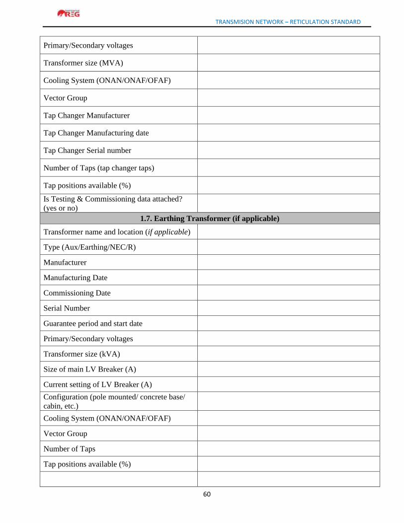
TRANSMISION NETWORK – RETICULATION STANDARD
60
Primary/Secondary voltages
Transformer size (MVA)
Cooling System (ONAN/ONAF/OFAF)
Vector Group
Tap Changer Manufacturer
Tap Changer Manufacturing date
Tap Changer Serial number
Number of Taps (tap changer taps)
Tap positions available (%)
Is Testing & Commissioning data attached?
(yes or no)
1.7. Earthing Transformer (if applicable)
Transformer name and location (if applicable)
Type (Aux/Earthing/NEC/R)
Manufacturer
Manufacturing Date
Commissioning Date
Serial Number
Guarantee period and start date
Primary/Secondary voltages
Transformer size (kVA)
Size of main LV Breaker (A)
Current setting of LV Breaker (A)
Configuration (pole mounted/ concrete base/
cabin, etc.)
Cooling System (ONAN/ONAF/OFAF)
Vector Group
Number of Taps
Tap positions available (%)
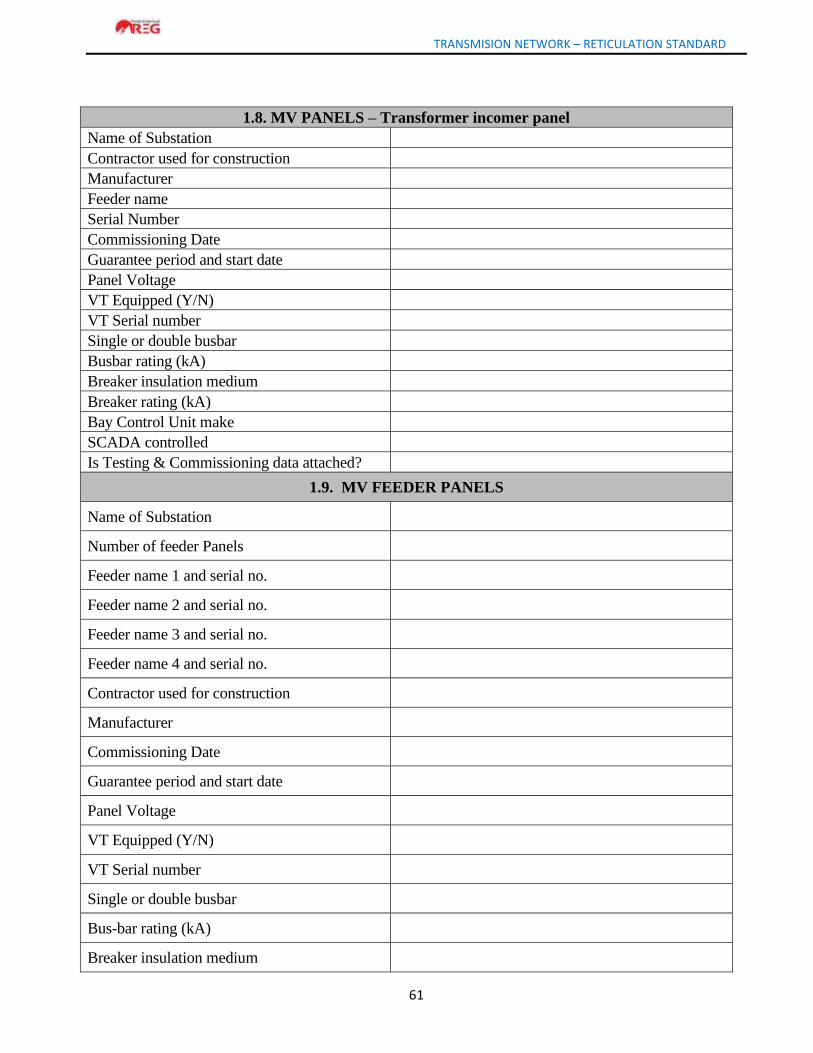
TRANSMISION NETWORK – RETICULATION STANDARD
61
1.8. MV PANELS – Transformer incomer panel
Name of Substation
Contractor used for construction
Manufacturer
Feeder name
Serial Number
Commissioning Date
Guarantee period and start date
Panel Voltage
VT Equipped (Y/N)
VT Serial number
Single or double busbar
Busbar rating (kA)
Breaker insulation medium
Breaker rating (kA)
Bay Control Unit make
SCADA controlled
Is Testing & Commissioning data attached?
1.9. MV FEEDER PANELS
Name of Substation
Number of feeder Panels
Feeder name 1 and serial no.
Feeder name 2 and serial no.
Feeder name 3 and serial no.
Feeder name 4 and serial no.
Contractor used for construction
Manufacturer
Commissioning Date
Guarantee period and start date
Panel Voltage
VT Equipped (Y/N)
VT Serial number
Single or double busbar
Bus-bar rating (kA)
Breaker insulation medium
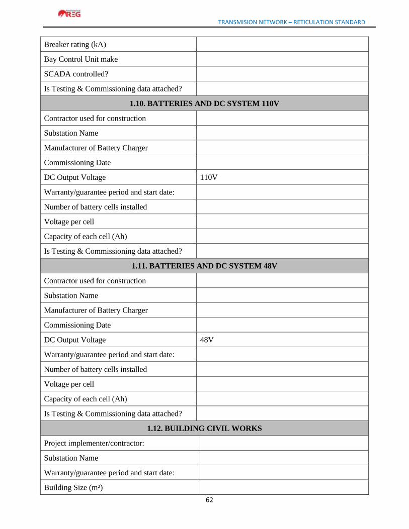
TRANSMISION NETWORK – RETICULATION STANDARD
62
Breaker rating (kA)
Bay Control Unit make
SCADA controlled?
Is Testing & Commissioning data attached?
1.10. BATTERIES AND DC SYSTEM 110V
Contractor used for construction
Substation Name
Manufacturer of Battery Charger
Commissioning Date
DC Output Voltage 110V
Warranty/guarantee period and start date:
Number of battery cells installed
Voltage per cell
Capacity of each cell (Ah)
Is Testing & Commissioning data attached?
1.11. BATTERIES AND DC SYSTEM 48V
Contractor used for construction
Substation Name
Manufacturer of Battery Charger
Commissioning Date
DC Output Voltage 48V
Warranty/guarantee period and start date:
Number of battery cells installed
Voltage per cell
Capacity of each cell (Ah)
Is Testing & Commissioning data attached?
1.12. BUILDING CIVIL WORKS
Project implementer/contractor:
Substation Name
Warranty/guarantee period and start date:
Building Size (m²)
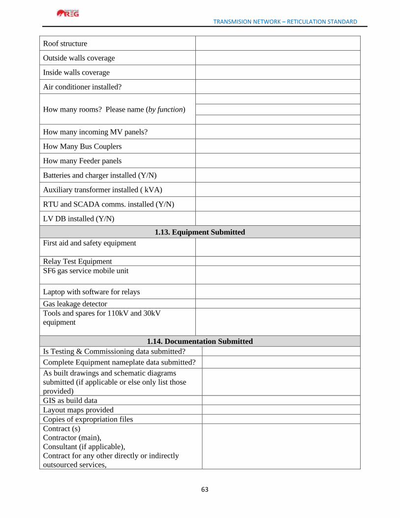
TRANSMISION NETWORK – RETICULATION STANDARD
63
Roof structure
Outside walls coverage
Inside walls coverage
Air conditioner installed?
How many rooms? Please name (by function)
How many incoming MV panels?
How Many Bus Couplers
How many Feeder panels
Batteries and charger installed (Y/N)
Auxiliary transformer installed ( kVA)
RTU and SCADA comms. installed (Y/N)
LV DB installed (Y/N)
1.13. Equipment Submitted
First aid and safety equipment
Relay Test Equipment
SF6 gas service mobile unit
Laptop with software for relays
Gas leakage detector
Tools and spares for 110kV and 30kV
equipment
1.14. Documentation Submitted
Is Testing & Commissioning data submitted?
Complete Equipment nameplate data submitted?
As built drawings and schematic diagrams
submitted (if applicable or else only list those
provided)
GIS as build data
Layout maps provided
Copies of expropriation files
Contract (s)
Contractor (main),
Consultant (if applicable),
Contract for any other directly or indirectly
outsourced services,

TRANSMISION NETWORK – RETICULATION STANDARD
64
Project has been completed Yes /No
Snags raised
Warranty/guarantee/Liability period, start & end
date
All As Built documents have been submitted
(drawings, As built and GIS information…) Yes /No
Comments and Other useful information:
RECEPTION NAMES POSITION SIGNATURE AND
DATE
For REG
For
Contractor/Implementer
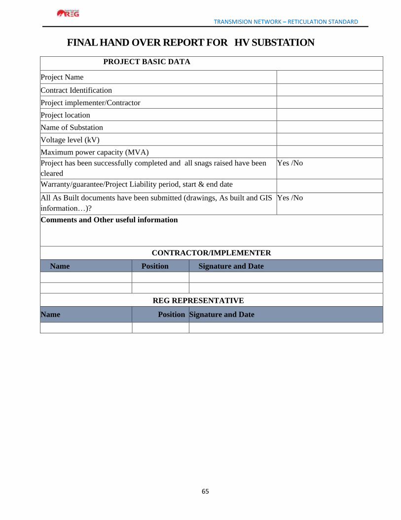
TRANSMISION NETWORK – RETICULATION STANDARD
65
FINAL HAND OVER REPORT FOR HV SUBSTATION
PROJECT BASIC DATA
Project Name
Contract Identification
Project implementer/Contractor
Project location
Name of Substation
Voltage level (kV)
Maximum power capacity (MVA)
Project has been successfully completed and all snags raised have been
cleared
Yes /No
Warranty/guarantee/Project Liability period, start & end date
All As Built documents have been submitted (drawings, As built and GIS
information…)?
Yes /No
Comments and Other useful information
CONTRACTOR/IMPLEMENTER
Name Position Signature and Date
REG REPRESENTATIVE
Name Position Signature and Date
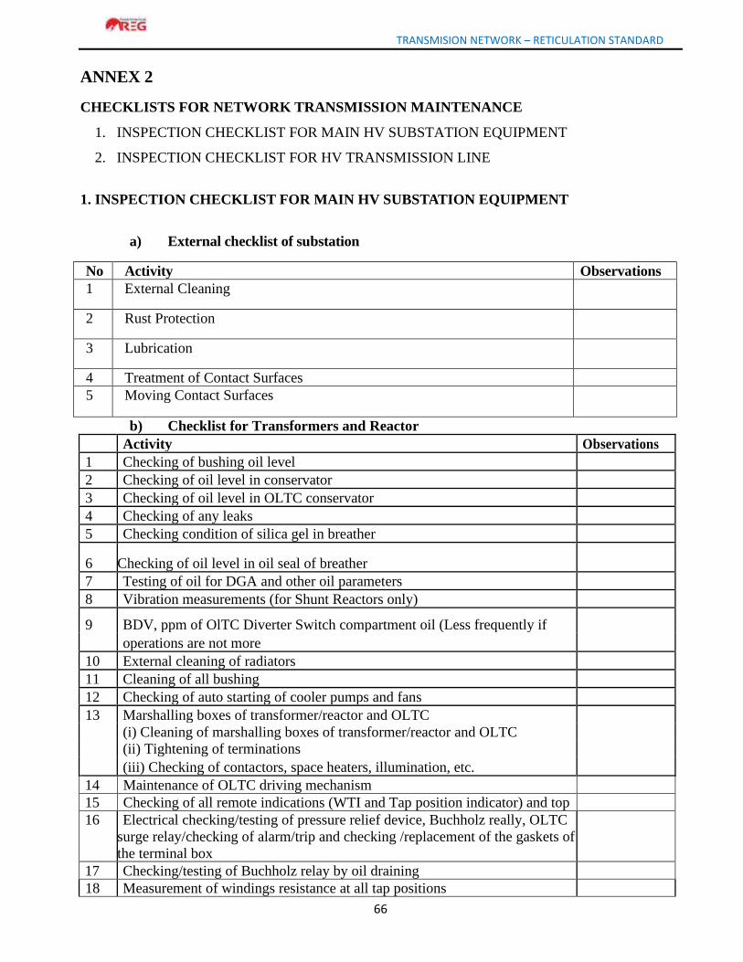
TRANSMISION NETWORK – RETICULATION STANDARD
66
ANNEX 2
CHECKLISTS FOR NETWORK TRANSMISSION MAINTENANCE
1. INSPECTION CHECKLIST FOR MAIN HV SUBSTATION EQUIPMENT
2. INSPECTION CHECKLIST FOR HV TRANSMISSION LINE
1. INSPECTION CHECKLIST FOR MAIN HV SUBSTATION EQUIPMENT
a) External checklist of substation
No Activity Observations
1 External Cleaning
2 Rust Protection
3 Lubrication
4 Treatment of Contact Surfaces
5 Moving Contact Surfaces
b) Checklist for Transformers and Reactor
Activity Observations
1 Checking of bushing oil level
2 Checking of oil level in conservator
3 Checking of oil level in OLTC conservator
4 Checking of any leaks
5 Checking condition of silica gel in breather
6 Checking of oil level in oil seal of breather
7 Testing of oil for DGA and other oil parameters
8 Vibration measurements (for Shunt Reactors only)
9 BDV, ppm of OlTC Diverter Switch compartment oil (Less frequently if
operations are not more
10 External cleaning of radiators
11 Cleaning of all bushing
12 Checking of auto starting of cooler pumps and fans
13 Marshalling boxes of transformer/reactor and OLTC
(i) Cleaning of marshalling boxes of transformer/reactor and OLTC
(ii) Tightening of terminations
(iii) Checking of contactors, space heaters, illumination, etc.
14 Maintenance of OLTC driving mechanism
15 Checking of all remote indications (WTI and Tap position indicator) and top
16 Electrical checking/testing of pressure relief device, Buchholz really, OLTC
surge relay/checking of alarm/trip and checking /replacement of the gaskets of
the terminal box
17 Checking/testing of Buchholz relay by oil draining
18 Measurement of windings resistance at all tap positions
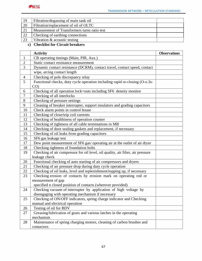
TRANSMISION NETWORK – RETICULATION STANDARD
67
19 Filtration/degassing of main tank oil
20 Filtration/replacement of oil of OLTC
21 Measurement of Transformers turns ratio test
22 Checking of earthing connections
23 Vibration & acoustic testing
c) Checklist for Circuit breakers
Activity Observations
1 CB operating timings (Main, PIR, Aux.)
2 Static contact resistance measurement
3 Dynamic contact resistance (DCRM), contact travel, contact speed, contact
wipe, arcing contact length
4 Checking of pole discrepancy relay
5 Functional checks, duty cycle operation including rapid re-closing (O-o.3s-
CO)
6 Checking of all operation lock=outs including SF6 density monitor
7 Checking of all interlocks
8 Checking of pressure settings
9 Cleaning of breaker interrupter, support insulators and grading capacitors
10 Check alarm points in control house
11 Checking of close/trip coil currents
12 Checking of healthiness of operation counter
13 Checking of tightness of all cable terminations in MB
14 Checking of door sealing gaskets and replacement, if necessary
15 Checking of oil leaks from grading capacitors
16 SF6 gas leakage test
17 Dew point measurement of SF6 gas/ operating air at the outlet of air dryer
18 Checking tightness of foundation bolts
19 Checking of air compressor for oil level, oil quality, air filter, air pressure
leakage check
20 Functional checking of auto starting of air compressors and dryers
21 Checking of air pressure drop during duty cycle operation
22 Checking of oil leaks, level and replenishment/topping up, if necessary
23 Checking erosion of contacts by erosion mark on operating rod or
measurement of gap
specified n closed position of contacts (wherever provided)
24 Checking vacuum of interrupter by application of high voltage by
disengaging with operating mechanism if necessary
25 Checking of ON/OFF indicators, spring charge indicator and Checking
manual and electrical operation
26 Testing of oil for BDV
27 Greasing/lubrication of gears and various latches in the operating
mechanism
28 Maintenance of spring charging motors, cleaning of carbon brushes and
contactors
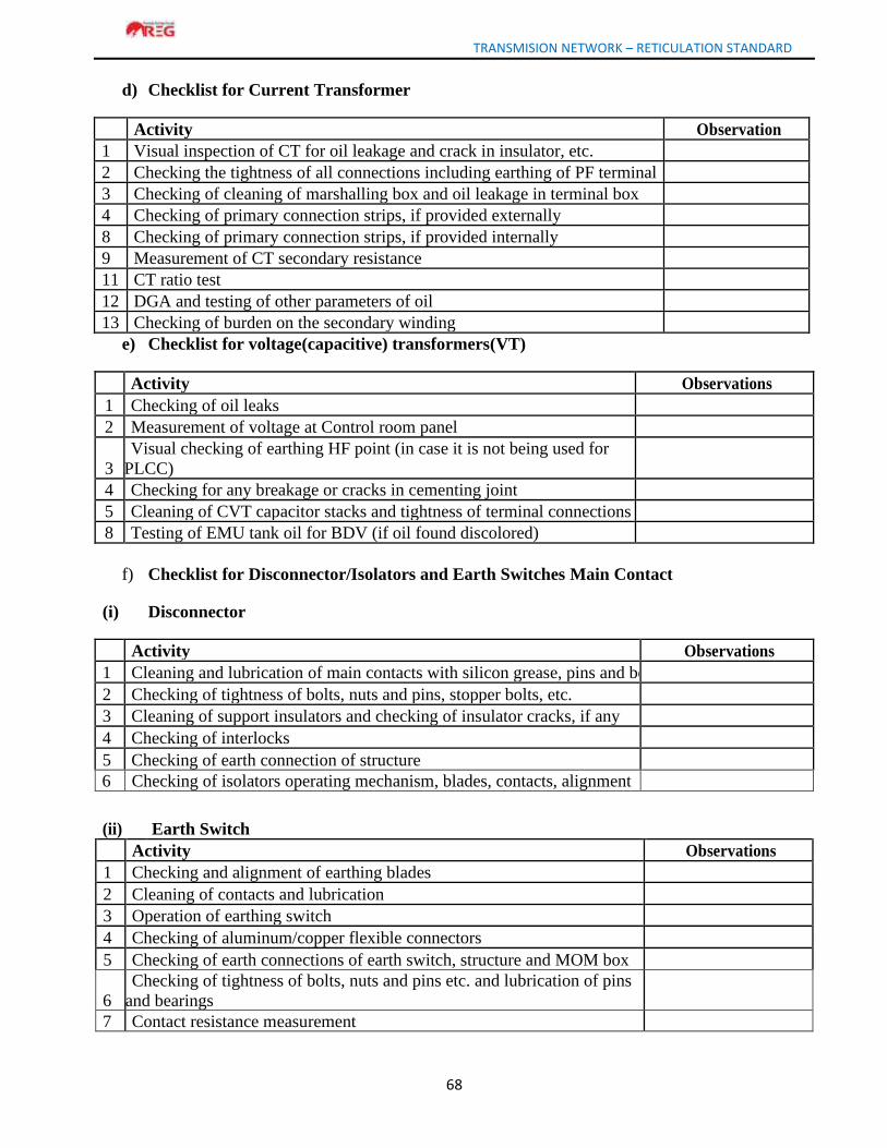
TRANSMISION NETWORK – RETICULATION STANDARD
68
d) Checklist for Current Transformer
Activity Observation
1 Visual inspection of CT for oil leakage and crack in insulator, etc.
2 Checking the tightness of all connections including earthing of PF terminal
3 Checking of cleaning of marshalling box and oil leakage in terminal box
4 Checking of primary connection strips, if provided externally
8 Checking of primary connection strips, if provided internally
9 Measurement of CT secondary resistance
11 CT ratio test
12 DGA and testing of other parameters of oil
13 Checking of burden on the secondary winding
e) Checklist for voltage(capacitive) transformers(VT)
Activity Observations
1 Checking of oil leaks
2 Measurement of voltage at Control room panel
3
Visual checking of earthing HF point (in case it is not being used for
PLCC)
4 Checking for any breakage or cracks in cementing joint
5 Cleaning of CVT capacitor stacks and tightness of terminal connections
8 Testing of EMU tank oil for BDV (if oil found discolored)
f) Checklist for Disconnector/Isolators and Earth Switches Main Contact
(i) Disconnector
Activity Observations
1 Cleaning and lubrication of main contacts with silicon grease, pins and bearings
2 Checking of tightness of bolts, nuts and pins, stopper bolts, etc.
3 Cleaning of support insulators and checking of insulator cracks, if any
4 Checking of interlocks
5 Checking of earth connection of structure
6 Checking of isolators operating mechanism, blades, contacts, alignment
(ii) Earth Switch
Activity Observations
1 Checking and alignment of earthing blades
2 Cleaning of contacts and lubrication
3 Operation of earthing switch
4 Checking of aluminum/copper flexible connectors
5 Checking of earth connections of earth switch, structure and MOM box
6
Checking of tightness of bolts, nuts and pins etc. and lubrication of pins
and bearings
7 Contact resistance measurement

TRANSMISION NETWORK – RETICULATION STANDARD
69
g) Checklist for Lightning (Surge Arresters)
Activity Observations
1 Checking of leakage current (Third harmonic resistive current)
2 Testing of counters and leakage current meters
3 Cleaning of insulator
4
Checking of earth connections between surge arrester, surge monitor and
earth
6 Check for status of surge monitors
h) Check list for Bus Bar, jumpers, connectors, clamps, switchyard illumination, etc.
Activity Observations
1 Measurement of station earth resistance
2 Cleaning of insulators
3 Checking of insulators for cracks
4
Thermovision scanning of all conductor joints, terminal
connectors/clamps
5 Checking of earthing connection of all structures
5 Removal of hot spots
6 De-weeding of switchyard
7 Checking of switchyard lighting
i) Checklist for Capacitors
Activity Observations
1 Checking of leakage of oil
2 Unbalance in capacitors by checking open delta voltage
3 Physical checks, Tightness
4 IR value
5 Leakage current measurement
6 Cleaning of insulators/bushings and tightening of connections
7 Capacitance measurement of capacitor cells
8 Checking of Protection relays for adopted setting
9 Checking tightness of earth connection and foundation bolts
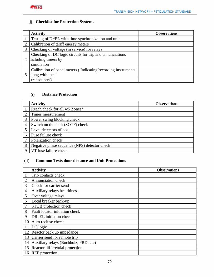
TRANSMISION NETWORK – RETICULATION STANDARD
70
j) Checklist for Protection Systems
Activity Observations
1 Testing of Dr/EL with time synchronization and unit
2 Calibration of tariff energy meters
3 Checking of voltage (in service) for relays
4
Checking of DC logic circuits for trip and annunciations
including timers by
simulation
5
Calibration of panel meters ( Indicating/recording instruments
along with the
transducers)
(i) Distance Protection
Activity Observations
1 Reach check for all 4/5 Zones*
2 Times measurement
3 Power swing blocking check
4 Switch on the fault (SOTF) check
5 Level detectors of pps.
6 Fuse failure check
7 Polarization check
8 Negative phase sequence (NPS) detector check
9 VT fuse failure check
(ii) Common Tests door distance and Unit Protections
Activity Observations
1 Trip contacts check
2 Annunciation check
3 Check for carrier send
4 Auxiliary relays healthiness
5 Over voltage relays
6 Local breaker back-up
7 STUB protection check
8 Fault locator initiation check
9 DR. EL initiation check
10 Auto recluse check
11 DC logic
12 Reactor back up impedance
13 Carrier send for remote trip
14 Auxiliary relays (Buchholz, PRD, etc)
15 Reactor differential protection
16 REF protection
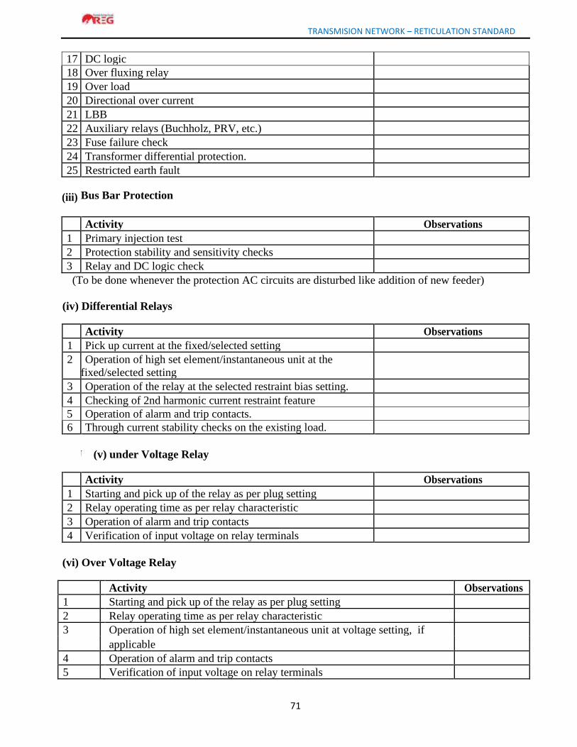
TRANSMISION NETWORK – RETICULATION STANDARD
71
17 DC logic
18 Over fluxing relay
19 Over load
20 Directional over current
21 LBB
22 Auxiliary relays (Buchholz, PRV, etc.)
23 Fuse failure check
24 Transformer differential protection.
25 Restricted earth fault
(iii)
Bus Bar Protection
Activity Observations
1 Primary injection test
2 Protection stability and sensitivity checks
3 Relay and DC logic check
(To be done whenever the protection AC circuits are disturbed like addition of new feeder)
(iv) Differential Relays
Activity Observations
1 Pick up current at the fixed/selected setting
2 Operation of high set element/instantaneous unit at the
fixed/selected setting
3 Operation of the relay at the selected restraint bias setting.
4 Checking of 2nd harmonic current restraint feature
5 Operation of alarm and trip contacts.
6 Through current stability checks on the existing load.
(v) U (v) under Voltage Relay
Activity Observations
1 Starting and pick up of the relay as per plug setting
2 Relay operating time as per relay characteristic
3 Operation of alarm and trip contacts
4 Verification of input voltage on relay terminals
(vi) Over Voltage Relay
Activity Observations
1 Starting and pick up of the relay as per plug setting
2 Relay operating time as per relay characteristic
3 Operation of high set element/instantaneous unit at voltage setting, if
applicable
4 Operation of alarm and trip contacts
5 Verification of input voltage on relay terminals
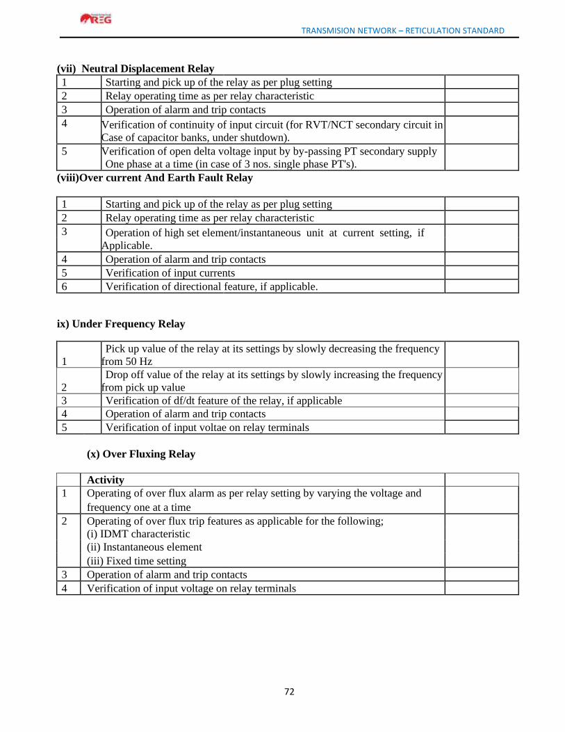
TRANSMISION NETWORK – RETICULATION STANDARD
72
(vii) Neutral Displacement Relay
1 Starting and pick up of the relay as per plug setting
2 Relay operating time as per relay characteristic
3 Operation of alarm and trip contacts
4 Verification of continuity of input circuit (for RVT/NCT secondary circuit in
Case of capacitor banks, under shutdown).
5
Verification of open delta voltage input by by-passing PT secondary supply
One phase at a time (in case of 3 nos. single phase PT's).
(viii)Over current And Earth Fault Relay
1 Starting and pick up of the relay as per plug setting
2 Relay operating time as per relay characteristic
3 Operation of high set element/instantaneous unit at current setting, if
Applicable.
4 Operation of alarm and trip contacts
5 Verification of input currents
6 Verification of directional feature, if applicable.
ix) Under Frequency Relay
1
Pick up value of the relay at its settings by slowly decreasing the frequency
from 50 Hz
2
Drop off value of the relay at its settings by slowly increasing the frequency
from pick up value
3 Verification of df/dt feature of the relay, if applicable
4 Operation of alarm and trip contacts
5 Verification of input voltae on relay terminals
(x) Over Fluxing Relay
Activity
1 Operating of over flux alarm as per relay setting by varying the voltage and
frequency one at a time
2 Operating of over flux trip features as applicable for the following;
(i) IDMT characteristic
(ii) Instantaneous element
(iii) Fixed time setting
3 Operation of alarm and trip contacts
4 Verification of input voltage on relay terminals
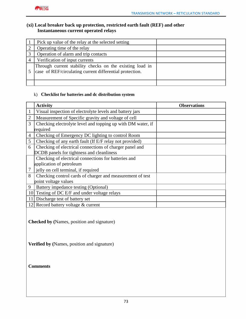
TRANSMISION NETWORK – RETICULATION STANDARD
73
(xi) Local breaker back up protection, restricted earth fault (REF) and other
Instantaneous current operated relays
1 Pick up value of the relay at the selected setting
2 Operating time of the relay
3 Operation of alarm and trip contacts
4 Verification of input currents
5
Through current stability checks on the existing load in
case of REF/circulating current differential protection.
k) Checklist for batteries and dc distribution system
Activity Observations
1 Visual inspection of electrolyte levels and battery jars
2 Measurement of Specific gravity and voltage of cell
3 Checking electrolyte level and topping up with DM water, if
required
4 Checking of Emergency DC lighting to control Room
5 Checking of any earth fault (If E/F relay not provided)
6 Checking of electrical connections of charger panel and
DCDB panels for tightness and cleanliness
Checking of electrical connections for batteries and
application of petroleum
7 jelly on cell terminal, if required
8 Checking control cards of charger and measurement of test
point voltage values
9 Battery impedance testing (Optional)
10 Testing of DC E/F and under voltage relays
11 Discharge test of battery set
12 Record battery voltage & current
Checked by (Names, position and signature)
Verified by (Names, position and signature)
Comments
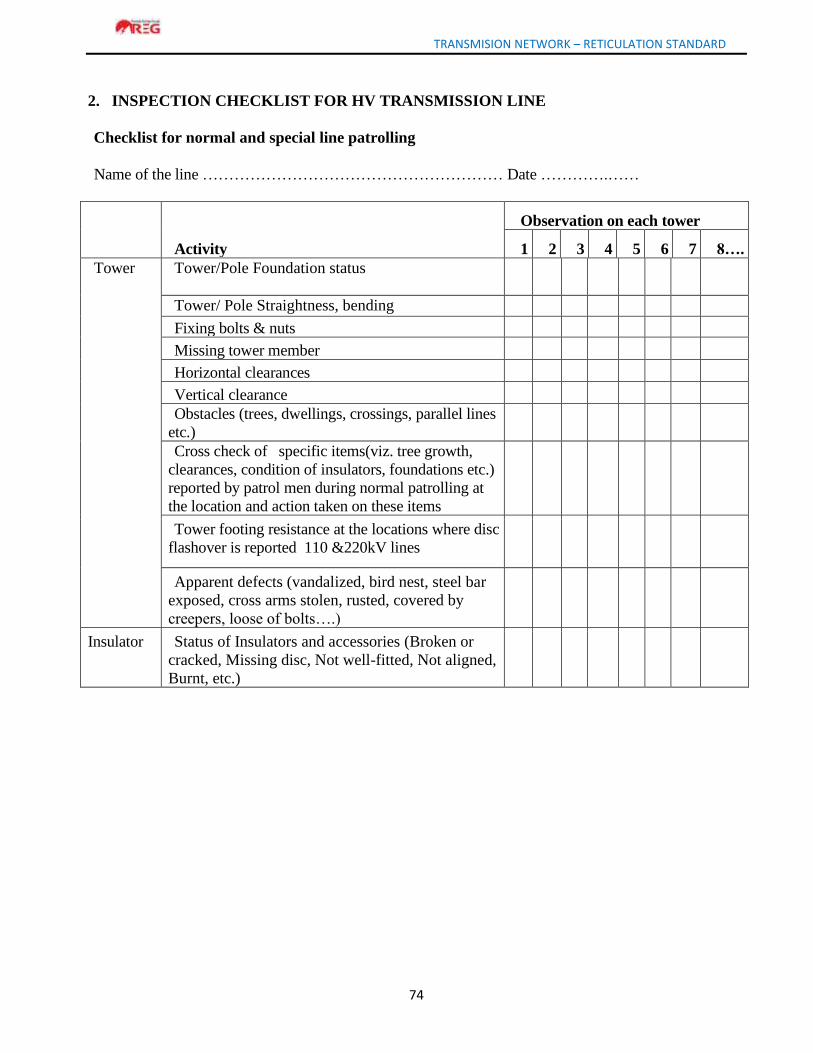
TRANSMISION NETWORK – RETICULATION STANDARD
74
2. INSPECTION CHECKLIST FOR HV TRANSMISSION LINE
Checklist for normal and special line patrolling
Name of the line ………………………………………………… Date ………….……
Activity
Observation on each tower
1 2 3 4 5 6 7 8….
Tower
Tower/Pole Foundation status
Tower/ Pole Straightness, bending
Fixing bolts & nuts
Missing tower member
Horizontal clearances
Vertical clearance
Obstacles (trees, dwellings, crossings, parallel lines
etc.)
Cross check of specific items(viz. tree growth,
clearances, condition of insulators, foundations etc.)
reported by patrol men during normal patrolling at
the location and action taken on these items
Tower footing resistance at the locations where disc
flashover is reported 110 &220kV lines
Apparent defects (vandalized, bird nest, steel bar
exposed, cross arms stolen, rusted, covered by
creepers, loose of bolts….)
Insulator Status of Insulators and accessories (Broken or
cracked, Missing disc, Not well-fitted, Not aligned,
Burnt, etc.)
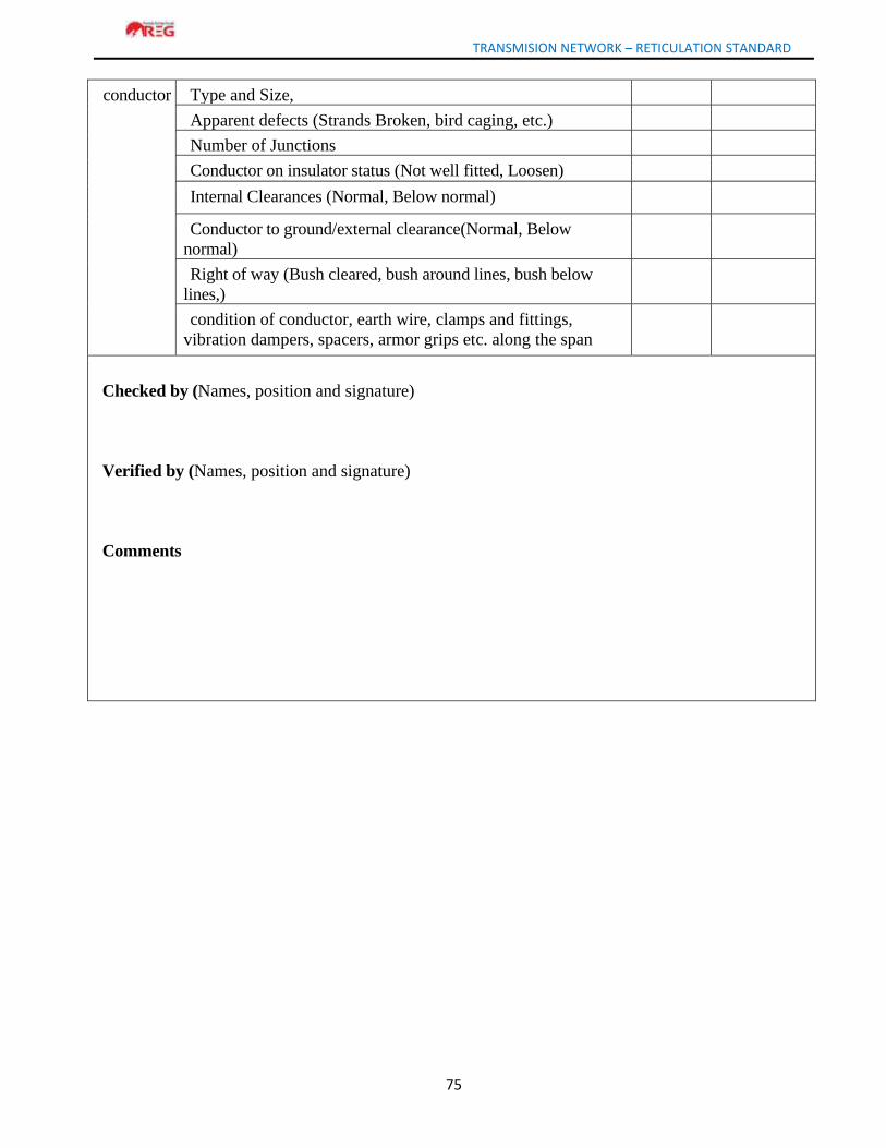
TRANSMISION NETWORK – RETICULATION STANDARD
75
conductor Type and Size,
Apparent defects (Strands Broken, bird caging, etc.)
Number of Junctions
Conductor on insulator status (Not well fitted, Loosen)
Internal Clearances (Normal, Below normal)
Conductor to ground/external clearance(Normal, Below
normal)
Right of way (Bush cleared, bush around lines, bush below
lines,)
condition of conductor, earth wire, clamps and fittings,
vibration dampers, spacers, armor grips etc. along the span
Checked by (Names, position and signature)
Verified by (Names, position and signature)
Comments