transport betweentwistedgraphene layers - arxiv · transport betweentwistedgraphene layers r....
TRANSCRIPT

arX
iv:1
002.
2983
v1 [
cond
-mat
.mes
-hal
l] 1
6 Fe
b 20
10
Transport Between Twisted Graphene Layers
R. Bistritzer and A.H. MacDonald1
1Department of Physics, The University of Texas at Austin, Austin Texas 78712
(Dated: September 21, 2018)
Commensurate-incommensurate transitions are ubiquitous in physics and are often accompaniedby intriguing phenomena. In few-layer graphene (FLG) systems, commensurability between honey-comb lattices on adjacent layers is regulated by their relative orientation angle θ, which is in turndependent on sample preparation procedures. Because incommensurability suppresses inter-layerhybridization, it is often claimed that graphene layers can be electrically isolated by a relative twist,even though they are vertically separated by a fraction of a nanometer. We present a theory ofinterlayer transport in FLG systems which reveals a richer picture in which the specific conduc-tance depends sensitively on θ, single-layer Bloch state lifetime, in-plane magnetic field, and biasvoltage. We find that linear and differential conductances are generally large and negative nearcommensurate values of θ, and small and positive otherwise.
Experimental advances in the fabrication of graphene-based structures[1, 2] have now provided researchers witha multitude of systems that have strikingly distinct elec-tronic properties. By engineering the substrate un-derlying exfoliated samples [3–5], identifying exfoliatedfragments with folds[6], or controlling epitaxial growthconditions[7, 8], the size and shape of the honeycomblattice arrays [9, 10] and the number of graphene lay-ers and their orientations can all be varied. This struc-tural diversity nourishes hopes for a future carbon-basedelectronics[11] with band-structure and transport char-acteristics that can be tailored for different types of ap-plications.FLG has advantages over single-layer-graphene be-
cause it has a larger current-carrying capacity and be-cause its electronic properties are sensitive to more en-gineerable system parameters[12]. In nature it appearsin a variety of stacking arrangements, the most com-mon being Bernal and rhombohedral sequences which canform three dimensional lattices. It has been understoodfor some time[13] that in graphite θ can depart fromBernal values. With some interesting exceptions[5, 14],most recent studies of inter-layer twists in FLG have fo-cused on samples grown on SiC[15]. In particular Hasset. al. have demonstrated that orientational disorderis normally present in carbon-face SiC epitaxial FLGsamples[16]. The present work is motivated primarilyby the need to achieve a more complete understanding oftransport in these graphitic nanostructures, which cur-rently appear to provide the most promising platformfor applications.In a bilayer system, the relative rotation angle θ can be
classified as either commensurate or incommensurate[17].In the former case the misaligned bilayer system stillforms a crystal, albeit one with larger lattice vectors andmore than four atoms per unit cell. Commensurabilityoccurs at a countably infinite set of orientations; but theprobability that a randomly selected orientation angle iscommensurate vanishes. The energy bands of commensu-rate twisted multilayers disperse approximately linearlywith momentum [18–20], except at energies very close tothe Dirac point. However, the Dirac velocity is reduced
0 10 20 30 40 50 60−2
0
2
4
6
8
10
12
14
θlo
g 10(τ
−1
RC
) [H
z]
FIG. 1: Interlayer (RC) equilibration rate as a function oftwist angle θ. These results were calculated for two layerswith equal carrier densities (n = 5 × 1012cm−2) and ǫFτ =3, where ǫF is the Fermi energy and τ is the isolated-layerBloch state lifetime. The relaxation rate is dominated byseparate features that appear near every commensurate angle,but differ in strength by many orders of magnitude. The tailsof individual features have been cut-off in this plot in order toreveal weaker features that will emerge in more ideal bilayers.Except near θ = 0, the equilibration rate is surprisingly slowfor two layers separated by an atomic length scale.
compared to that of a single layer system especially forrotation angles close to 0 or 60[14, 19]. The linearDirac-like dispersion contrasts with the approximatelyquadratic dispersion found in a Bernal stacked bilayersystem[21]. Incommensurate bilayers are not crystallineand therefore their electronic properties cannot be ana-lyzed using Bloch’s theorem.
Here we develop a theory of the vertical transportproperties of twisted FLG samples which is valid in theincoherent transport limit[22]. We show that the spe-cific linear conductance between misaligned layers is en-hanced over a small but finite range of twist angles nearthose that produce relatively short period commensuratestructures, that the conductance peak angles shift within-plane magnetic field B‖, and that the peaks becomenarrower and stronger when the isolated layer Bloch statelifetime τ increases. The differential conductivity tends
2
to be negative near commensurate conductance peaksand positive otherwise. Typical theoretical results forthe dependence of the interlayer equilibration rate on θare presented in Fig. 1. In the following we first explainthe analysis which supports these statements and thendiscuss some implications for FLG electronics.Studies of transport between weakly coupled two-
dimensional (2D) electron systems have a long history[24,25] in semiconductor heterojunctions systems. In thatcase epitaxial tunnel barriers are responsible for nearlyperfect 2D momentum conservation, which then helps tomake vertical transport a powerful probe of electronicproperties. Our theory of vertical transport in FLG issimilar to the successful semiconductor heterojunctiontheory[24]. We derive an expression for tunneling currentI vs. bias voltage V by using a π-orbital tight-bindingmodel, approximating inter-layer hopping processes atleading order in perturbation theory, and accounting forthe inevitable presence of a finite disorder potential whichlimits the life-times of Bloch states in each layer. Thesesteps lead to
I(θ) = egs
∫
dω
2π[nF1(ω)− nF2(ω + eV )]
∑
kp′
|Tαβkp′|2A1α(k, ω)A2β(p
′, ω + eV ), (1)
where gs = 2 accounts for spin degeneracy, Aiα(k, ω) isthe spectral function for band α and layer i, nFi is the
Fermi distribution function for layer i, and Tαβkp′ is the
tunneling matrix element between isolated layer Blochstates with band and crystal momentum labels, |kα〉 and|p′β〉. The sums over k and p′ may be taken over theunrotated and rotated Brillouin zones respectively. Wederive Eq. (1) in section 2 of the Supplementary Infor-mation , where we justify its neglect of disorder vertex-corrections. In our calculations, A is approximated bya Lorentzian function with full-width-half-maximum ~/τcentered on the band energy ǫiα(k). (Hereafter ~ = 1 andlength is measured in units of ac = 1.42A, the carbon-carbon distance in graphene.) Eq. (1) is valid in theweak tunneling regime in which T is smaller than life-time broadening 1/τ , allowing coherent tunneling pro-cesses to be neglected. This condition is satisfied in typ-ical samples except at rotation angles very close to 0 or60.In a twisted bilayer system the tunneling matrix ele-
ment depends strongly on the relative orientation of thetwo graphene sheets. The honeycomb lattice vectors ofthe rotated layer R′ are related to those of the unrotatedlayer R by R′ = M(θ)R + d. Here M is the trans-formation matrix for rotations in the lattice plane andd is a translation vector. Corresponding rotations oc-cur in reciprocal space so that ǫ1α(p) = ǫ2α(p
′) whenp′ = M(θ)p. Commensurability is determined only byM , but linear translations of one layer relative to theother do modify T , and hence the tunneling current.The magnitude of T depends on the π-orbital interlayer
hopping amplitudes of our tight-binding model which we
estimate using a simple two center approximation schemeexplained in section 1 of the Supplementary Information.We find that
Tαβkp′ =
1
Ω0
∑
s,s
(a(α)ks )⋆a
(β)ps
∑
G1G2
tk+G1e−i(k+G1)·d
× eiG1·τse−iG2·τs δk+G1,p′+G′
2(2)
where Ω0 is the area of a unit cell. Here G1 and G2 aresummed over reciprocal lattice vectors, primed wavevec-tors are rotated, s and s label the two triangular hon-
eycomb sublattices centered at positions τs, and a(α)ks is
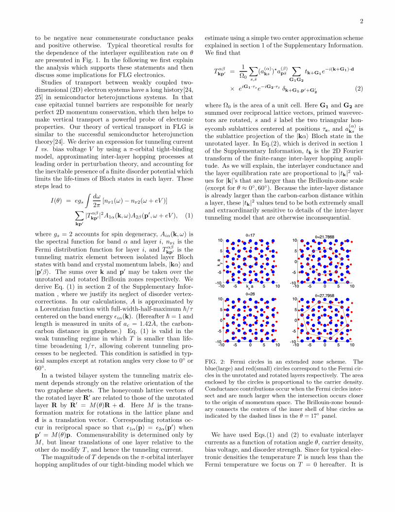
the sublattice projection of the |kα〉 Bloch state in theunrotated layer. In Eq.(2), which is derived in section 1of the Supplementary Information, tk is the 2D Fouriertransform of the finite-range inter-layer hopping ampli-tude. As we will explain, the interlayer conductance andthe layer equilibration rate are proportional to |tk|2 val-ues for |k|’s that are larger than the Brillouin-zone scale(except for θ ≈ 0, 60). Because the inter-layer distanceis already larger than the carbon-carbon distance withina layer, these |tk|2 values tend to be both extremely smalland extraordinarily sensitive to details of the inter-layertunneling model that are otherwise inconsequential.
FIG. 2: Fermi circles in an extended zone scheme. Theblue(large) and red(small) circles correspond to the Fermi cir-cles in the unrotated and rotated layers respectively. The areaenclosed by the circles is proportional to the carrier density.Conductance contributions occur when the Fermi circles inter-sect and are much larger when the intersection occurs closerto the origin of momentum space. The Brillouin-zone bound-ary connects the centers of the inner shell of blue circles asindicated by the dashed lines in the θ = 17 panel.
We have used Eqs.(1) and (2) to evaluate interlayercurrents as a function of rotation angle θ, carrier density,bias voltage, and disorder strength. Since for typical elec-tronic densities the temperature T is much less than theFermi temperature we focus on T = 0 hereafter. It is

3
helpful to first focus on the linear conductance
G(θ) =e2gs2π
∑
kp′
|Tαβkp′|2A1α(k, ǫF)A2β(p
′, ǫF). (3)
The equilibration rate plotted in Fig.1 was obtained byviewing the bilayer as a leaky capacitor and ignoring anyscreening by graphene σ orbitals. This model yields anRC circuit with time constant τRC related to the conduc-tance by G/A = 0.027 τ−1
RCwhere A is the layer area in
m2, G is measured in Siemens, and τRC in seconds. Apartfrom a change in scale, Fig.1 can then be viewed as a plotof the interlayer conductance. We find that the tunnelingconductance increases abruptly near commensurate an-gles, that the height of the peaks scales linearly with ǫFτ(for ǫFτ > 1), and that the peaks narrow as τ increases.The discontinuous jumps of log(G) in Fig.1 are artificialand result from a numerical procedure in which momentak and p′ in Eq.(3) are restricted to the vicinity of theFermi energy. This procedure suppresses the tails of allcommensurate features, allowing more minor features tobe revealed. In practice the conduction tails correspond-ing to highly commensurate structures will dominate Gover a range of angles that depends on τ . Limited bycomputational power we considered τ−1 ≈ 75 meV inFig.1 however in epitaxial graphene the lifetime can bemore than an order of magnitude longer[26]. An accu-rate theory of the conduction-peak tails would requirea reliable theory of the isolated-layer spectral functiontails.Why is the tunneling conductance enhanced at com-
mensurate rotation angles? To understand the relationbetween interlayer current and commensurability it is il-luminating to plot the Fermi surfaces of both layers, pe-riodically extended in momentum space by adding re-ciprocal lattice vectors to the crystal momenta of theelectrons. As we see in Eq.( 2), allowed interlayer tun-neling processes are diagonal in this generalized momen-tum. The left panels in Fig.2 corresponds to the in-commensurate rotation angles θ = 17, 26 whereas theright panels correspond to the commensurate angles nearθ = 21.8, 27.8. We use different Fermi surfaces sizes forclarity; similar considerations apply independent of thesign or magnitude of the carrier density ratio. The keyfeature to notice in these plots is that at commensuraterotation angles some Fermi spheres overlap. Overlapsof circles centered on the extended Dirac points, alwaysaccompany commensurate real-space structures becausethe set of extended Dirac points forms a momentum spacehoneycomb lattice that differs from the real space honey-comb lattice only by a scale factor and by a rotation. Ifoverlaps occur in real-space, they also occur in momen-tum space. Notice that this property holds only whenthe Brillouin-zone corners are extended to fill momentumspace; if the Dirac point occurred elsewhere in the iso-lated layer Brillouin-zone, the dependence of inter-layerconductance on θ would be quite different.The overlap of extended Dirac points does not fully ex-
plain the conductance peaks at finite density, since Fermi
energy states at finite carrier density are displaced fromthe Dirac point. The nesting between Fermi surfaces al-luded to in Fig.2 actually depends not only on commen-surability, but also on the fact that for typical carrierdensities the Fermi surface is well approximated by acircle centered on the Brillouin-zone corners. For equaldensities then, matching Dirac points implies completeFermi surface nesting (see Fig.3). When the two-layershave different densities, the peak conductance will notoccur at the nesting angle; instead the conductance willhave a double-peak structure with features offset to bothsides of the commensurate angle.Commensurate rotation angles can be classified as ei-
ther inter-valley or intra-valley. In the former the twoDirac points kD and k′
Dthat coincide in the extended
momentum picture are associated with different valleys(in the aligned bilayer) whereas for intra-valley rotationangles they belong to the same valley. An inter-valleycommensurate rotation is illustrated in Fig.3.Away from commensurate angles the energy differ-
ence between states which have the same extended mo-mentum is typically much larger than the Fermi energy,and the spectral function width 1/τ (see left panels ofFig.2). The conductance is therefore very small awayfrom the commensurate-angle peaks. The Dirac-like lin-ear spectrum of an ideal commensurately twisted bilayerdoes not, as is commonly stated, indicate that the idealtwisted layers are decoupled. At commensurate anglesthe perfect crystal wavefunctions near the Dirac point arein fact coherent equal weight contributions from the twolayers. In the limit of large in-plane Bloch state lifetimes,the conductance becomes very large and eventually theincoherent transport picture will fail.
FIG. 3: Nesting of Dirac cones at commensurability. Forcommensurate rotation angles every momenta state on therotated Fermi circle is mapped onto a momenta state of anunrotated Fermi circle.
As we have explained, vertical transport at commen-surability is dominated by processes in which an electrontunnels from a momentum near a Dirac point of one layer,to a momentum that is the same distance from a Diracpoint of the other layer. Since carrier densities per unitcell are always small, we can replace tk+G in Eq.( 2) by

4
tkD+G where kD is the Dirac point momentum. We thenfind that the conductance peak can be expressed as theproduct of geometry-related and phase space factors:
G ≈ R(θc,d)∑
k
A1(k, ǫF)A1(k, ǫF), (4)
where θc is the commensurate orientation. R(θc,d) de-pends mainly on the value of t|kD+G| at which the ex-tended Dirac points overlap (see Fig.2), while the re-maining phase space factor is identical to the one thatappears in the theory of coupled quantum wells[24]. Forequal densities in the two layers, the Fermi surfaces nestprecisely. For pure rotations R can be calculated analyt-ically. For inter-valley commensurate rotation angles wefind that
G(θc) = Agsgve2
~
ǫFτE2g (θc)
16πv2. (5)
Here Eg is the energy difference between the top con-duction band and bottom valence band of the twistedbilayer at the Dirac point, and we assumed that ǫFτ > 1.In section 4 of the Supplementary Information we deriveEq.(30) and obtain a similar formula for intra-valley ro-tation angles. In addition we numerically verify that theconductance changes only by a factor of order unity as dis varied across the unit cell. Eq.(30) therefore provides agood estimate for G regardless of the relative translationbetween the two layers (see section 3 of the Supplemen-tary Information).When the densities differ, Fermi circles in different lay-
ers begin to overlap near θ = θc only after a momentum-space relative shift Q equal in magnitude to the differ-ence of the two Fermi wavevectors. As in semiconductordouble-wells[24, 25, 27], a shift Q = z × ed⊥/l
2H, where
lH is the magnetic length, can be accomplished in a bi-layer with layer separation d⊥ by applying an in-planemagnetic field B‖e. For graphene bilayers, however, arelative momentum space shift can also be achieved byrotation, as is clear from Fig.2. For small departuresfrom commensurability Q ≈ (θ − θc) z × (kD +G). Forequal densities, both rotations and in-plane fields dra-matically suppress the conductance peak when vQ ≥ 1/τwhere v is the band velocity of graphene. For example,for n = 4 · 1012cm−2 and τ = 50 fsec [31], the conduc-tance peak should nearly completely disappear at 0.15Tesla. FLG should therefore provide a palette on whichgate voltages, in-plane magnetic fields, and rotations canbe mixed to produce a rainbow of interrelated and ex-traordinarily strong magnetic-field and strain sensitiveresistance effects.In general the interlayer conductance G(θ) is peaked
whenever any extended Fermi surface overlap occurs atreasonably small reciprocal lattice vectors. The degree ofoverlap can be parameterized by q⋆, the minimum sepa-ration between extended Dirac points of the rotated andunrotated layers for a reciprocal lattice vector truncationchosen to reflect the scale on which tq falls off. For a clean
0 20 40 600
0.5
1
1.5
2
2.5
θ
q*
intra−valleyinter−valley
FIG. 4: The minimum separation between extended Diracpoints q⋆ as a function of rotation angle θ.
system, tunneling conductance at equal density is appre-ciable as long as q⋆ ≈ |θ − θc||k+G| < 2kF. Because2kF in FLG electronic systems is always small comparedto reciprocal lattice vector scales, the conductance peaksare invariably sharp when plotted as a function of θ. Asan example q⋆ ≈ 6.39|θ− θc| in the vicinity of θc = 27.8
for the reciprocal lattice vector illustrated in Fig.2. InFig.4, q⋆, minimized over the first two G-shells, is plot-ted as a function of angle. Overlap between the Fermispheres of the two layers will therefore persist over theangle range for which q⋆ is smaller than 2kF .Electronic structure calculations for ideal commensu-
rate bilayers demonstrate that Eg decreases very rapidlyas the number of atoms per unit cell increases[17]. Eg =780 meV for a unit cell of 4 atoms, and already lessthat 1 meV for a unit cell of 100 atoms. It is there-fore plausible that conductance tails that correspond tothe few most lowest order commensurate angles (e.g.θc = 0, 21.8, 27.8, 32.2, 38.2, 60) will dominate G atevery rotation angle. Eqs.(4) and (30) should thereforebe interpreted as a lower bound for the conductance athigher order commensurate θc’s.We now turn to the non-linear I−V of twisted bilayer
graphene. At zero temperature
I(θ, V ) =egs2π
∑
kp
|Tkp′ |2∫ ǫF
ǫF−eV
dωA1(k, ω)A2(p′, ω+eV ).
(6)We numerically find that the I-V curves at commensurateand incommensurate angles are drastically different. Atrelatively small bias voltage the currents correspondingto commensurate angles are several orders of magnitudelarger than their incommensurate counterparts. On theother hand negative differential conductances invariablyappear at commensurate angles, whereas dI/dV tends tobe small and positive at incommensurate angles.In classic tunneling experiments, a bias voltage induces
an equal electric potential difference between the layers.Total energy conservation then implies kinetic energychanges equal to eV upon tunneling. Since, as we haveexplained, the allowed tunneling processes at commen-surate angles are between states with the same kineticenergy bias voltages tend to decrease tunneling currents.Following the same approximations that led to Eq.(4) wecan capture this effect mathematically by expressing the

5
interlayer current in product form:
I =e
2π
∑
αβ
Rαβ(θ,d)
∫ ∞
−∞
dω [nF(ω)− nF(ω + V )]
×∑
K
Aα(k, ω)Aβ(k, ω + eV ) (7)
In Eq.( 7) we have allowed for both intraband and in-terband tunneling at large biases. As long as eV < ǫFtunneling between conduction bands dominate I whenboth layers are n-type. In this intermediate non-linearregime the two Lorentzian shaped spectral functions inEq.(7) overlap only weakly and
I(θc,d) ≈ G(θc,d)V
1 + (eV τ)2. (8)
for ǫFτ > 1. Negative differential conductance occurswhen eV τ > 1. For incommensurate twist angles, crys-tal momenta conservation can not be sustained at theFermi surface. Increasing V unblocks processes in whichtunneling occurs between states with different kinetic en-ergies and leads to a slow increase of the tunneling cur-rent with a complex dependence on tq and ~/τ . ForeV > ǫF, the current increases monotonically with V forboth commensurate and incommensurate twist angles.The commensurate tunneling current has a sharp rise ateV = 2ǫF due to momentum conserving processes allowedat high bias voltage in which a valence band electron inone layer tunnels to the conduction band of the oppo-site layer. For commensurate angles it follows from (7)that these inter-band processes eventually dominate thetunneling current and that
I ≈ e2
4v2RvcΘ(V − 2ǫF)V (9)
to leading order in 1/V τ . Here Θ is the Heaviside stepfunction. The finite temperature corrections to Eqs.(8,9)are exponentially small in T/ǫF.The extension of our theory to FLG is straightforward
in the linear regime. In the simplest case each layer is ro-tated with respect to its neighbors sufficiently to drivethe system into an incoherent transport regime. Theweak links between layers then act like classical resistorswhich appear in series in vertical transport. The resis-tance of each link depends on the rotation angle between
layers and on the densities in both layers. We anticipate avery rich and complex behavior of FLG in the non-linearregime. The negative differential conductivities are likelyto give rise to steady state multistability and to chaotictemporal response, as occurs in semiconductor multiple-quantum-well systems[32]. A more complicated scenariocould arise in turbostratic graphene. There the entirelayered structure is composed of a set of coherent multi-layer substructures, characterized by either a Bernal oran AA stacking sequence. Weak links which play a dom-inant role in limiting vertical conductance appear due tooccasional twists. The calculations for the resistance ofeach twisted interface closely follow those outlined abovefor the two-layer case when supplemented by a band in-dex for the various 2D energy bands of a coherent sub-structure.
One application of our theory is to assess whether ornot twisted graphene layers are effectively isolated froman electrical point of view. The equilibration time be-tween layers that are spatially uniform but out of equi-librium is plotted in Fig. 1 and is very long comparedto characteristic electronic time scales for rotation an-gles far from important commensurabilities, near 10 forexample. The steady-state equilibration length betweenseparately contacted layers can be estimated by equatinginter-layer conductances, which are proportional to sam-ple area, with the intra-layer conductance per square.For the commensurate angle θc = 21.8, for example, thesample area at which they are identical is approximately0.04µm2. As evident from Fig.1, the corresponding areasfor small rotation angles near the AA and AB stackingsequences are even smaller. For small rotation angles,the two layers are therefore strongly coupled.
Finally we remark that the extraordinary sensitivity ofthe tunneling conductance to the twist angle found heresuggests that misaligned graphene bilayers might be use-ful as ultra-sensitive strain gauges or pressure sensors[33]which are widely used in biological, mechanical and op-tical systems.
The authors acknowledge support from CERA, SWANand the Welch Foundation and helpful conversations withW. de Heer, R. Duine, P. First, D. Goldhaber-Gordon,R. Lifshitz, and E. Tutuc.
Supplementary Information
I. THE TUNNELING MATRIX ELEMENTS
The interlayer hopping terms in a π-band tight-binding Hamiltonian for twisted graphene bilayers depend in generalon the positions of all carbon atoms. Our analysis of inter-layer conductance and equilibration is based on a simpletwo-center model in which the interlayer hopping parameter between two sites, t(r), depends only on the planar

6
projection of their separation r. In the main text we used an equation, derived below, which relates the inter-layerhopping amplitudes of twisted bilayers to tq, the two-dimensional Fourier transform of t(r).One strategy which can be used to estimate t(r) is to assume functional forms for the distance dependence of the
Slater-Koster tppσ and tppπ hopping functions[34], and then fit them to accurately known parameters of untwistedbilayers. We have explored this approach, following the procedures adopted in Refs. [17, 28], but have concluded thatit tends to underestimate hopping amplitudes near the Dirac points of twisted bilayers. We have therefore decided toobtain numerical estimates by directly fitting an ansatz for tq to obtain
tq = t0 e−α(qd⊥)γ , (10)
where t0 = 2 eV A2, α = 0.13, γ = 1.25, and d⊥ = 3.34A is the distance between the layers. The value used for t0 isthe average of values implied by the models in Refs.[17, 28]. Since t0 is the sum of all inter-layer hopping parameters,it should be estimated reliably by any parameterization that uses accurate values for the largest hopping parameters.We fix α and γ so that the values of the ideal bilayer gaps are accurate for the lowest order commensurate structures.These are proportional to tkD
(θ = 0 and θ = 60) and t6.4/ac(θ = 21.8 and θ = 38.2) where ac = 1.42A is
the carbon-carbon distance in single layer graphene. See details in Sec. IV below. We fit the energy gaps to valuesextracted from the ab initio calculations by Shallcross et al.[17]. Note that these values of tq characterize short-distance roughness in the inter-layer hopping landscape which survives Fourier transformation at large wavevectors,which is not simply related to typical inter-layer hopping strengths. The energy gaps that we obtain at θ = 21.8
using the real space parameterizations of tppσ(r) and tppπ(r) in Refs. [17, 28] are both substantially smaller than theab initio gaps of Shallcross et al.[17].We now derive the expression for the hopping amplitude between Bloch states in twisted bilayers that is used in
the main text. The Bloch state in layer j with crystal momentum k and band index α can be written as
|Ψ(j)kα〉 = ajαkA
|ψ(j)kA
〉+ ajαkB|ψ(j)
kB〉 (11)
where A and B label the two triangular honeycomb sublattices,
(
a1αkA
a1αkB
)
=1√2
(
eiΘk
α
)
, (12)
and Θk is the phase of the inter-sublattice hopping term in the single-layer tight-binding model. For nearest neighbor
hopping within the planes Θk = arg(
∑
j eik·δj
)
where the δj are the three vectors connecting an atom with its nearest
neighbors. The Bloch state projection on sublattice s is
|ψ(1)ks 〉 =
1√N
∑
R
eik(R+τs)|τs +R〉, (13)
where |τs +R〉 is a site-representation basis function of the tight-binding model. In Eq.(13) R is a triangular latticevector, N is the number of unit cells in the system, and we choose τA = 0 and τB equal to the vector connecting thetwo atoms within a unit cell.The relative orientation of the two layers can be described by a rotation matrix M(θ) and a translation vector d.
Therefore every Bloch wave function in the second layer is related to a Bloch wave function in the first layer by
|Ψ(2)k′α〉 = |Ψ(1)
kα〉 (14)
with |R+ τs〉 in layer 1 replaced by |R′ + τ ′s〉 in layer 2, r′ =Mr+ d for all positions and k′ =Mk. Using primes toindicate layer 2 variables and invoking the two-center approximation for the inter-layer tunneling amplitude,
〈τs +R|Hinter |τ ′s +R′〉 = t(τs +R− τ ′s −R′), (15)
we find that
〈Ψkα|Hinter|Ψp′β〉 ≡ Tαβkp′ =
1
N
∑
ss′
(
a(α)ks
)⋆
a(β)ps′
∑
R1R2
e−ik·(R1+τs)+ip·(R′
2−d+τ ′
s′) t(R1 + τs −R′
2 − τ ′s′).
Expression (2) in the main text is obtained by Fourier expanding t(r) and summing over the lattice vectors.

7
II. VERTEX CORRECTIONS
The general expression for the tunneling current
I(θ, V ) = −4egs
∫
dω
2π
∑
Tαβk0p
′
0
T γδ⋆kNp′
N
[n2(ω + eV )− n1(ω)]
× ImGR
1γα(kN,k0, ω)ImGR
2βδ(p′0,p
′N, ω + eV ) (16)
is obtained using second order perturbation theory[35]. In Eq.(16) nj is the Fermi distribution in layer j, GR
jγα is theretarded Green function in layer j that correspond to the propagation of a charge carrier from band α to band γ, therotation angle is θ, and V is the bias voltage. The over-line denotes disorder averaging. As in the main text, primedvariables are associated with the rotated layer. Since disorder breaks translation invariance, the Green functions arenot diagonal is the momentum representation. When the disorder averages can be performed independently for thetwo-layers, translational invariance is recovered and Eq. (16) reduces to Eq.(1) of the main text.We average over disorder using the self-consistent Born approximation in which correlations between the layers
appear as a vertex-correction ladder diagram sum (see Fig.5). For simplicity we assume white noise disorder andcharacterize the correlation between the disorder potentials in the two layers by γ = ni〈U1U2〉 where ni is theconcentration of impurities and Uj is the disorder potential in layer j. For aligned bilayers with short range tunnelingwe find that
G =e2t2νFτ
2
1
1− γ/β(17)
where β = ni〈U2j 〉. As evident from Eq.(17) the tunneling conductance diverges if the disorder potentials of the
two layers are perfectly correlated. These strong correlations are likely in a graphene bilayer because of the smalldistance between the layers. The divergence of G indicates the breakdown of perturbation theory, i.e. it invalidatesthe incoherent theory we use in this work. A similar scenario arises for tunneling between coupled semiconductorquantum wells[23] when their disorder potentials are strongly correlated.We now show that vertex corrections are important only at very small values of the rotation angle θ. The physical
origin of this behavior is twofold. First, the relevant correlation in the twisted case is between the disorder potentialin one layer and a spatially rotated counterpart in the other layer. For any finite range disorder correlation length,these two disorder potentials are independent making γ in Eq.(17) considerably smaller. Second, the divergence inthe conductance appears due to tunneling between identical states. However, for incommensurate angles the wavevectors of the initial and final states in a tunneling process substantially differ making β in Eq.(17) considerablylarger. In the following paragraphs we explain how this latter behavior is captured in a diagrammatic perturbationtheory description of a disordered system.We first focus on the tunneling conductance for aligned layers (θ = 0). At zero temperature
G(θ) =2e2gsπ
∑
Tαβk0p
′
0
T γδ⋆kNp′
N
ImGR
1γα(kN,k0, ǫF)ImGR
2βδ(p′0,p
′N, ǫF). (18)
The conservation of crystal momentum in expression (2) for Tαβkp′ implies that p0 = k0 and that pN = kN. For
. . . . .
k0kN
0
K0+q
0+qN
q
FIG. 5: Self consistent Born approximation. A bubble diagram with ladders.
ǫFτ > 1 interband transitions are inhibited so that α = γ and β = δ. Due to the spinor form of the wave functionseach disorder line contributes [1 + cos(θkj+1
− θkj)]γ/2 to the ladder diagram. To evaluate Π(n), the ladder diagram
8
with n disorder lines, we first integrate over the angular variables using
∫ 2π
0
dθq2π
cos(θk1− θq) cos(θk2
− θq) =1
2cos(θk1
− θk2). (19)
Then using F(0) = 2πνFτ where
F(Q) =∑
q
GR1α(q, ω)G
A1α(q+Q, ω) (20)
we integrate over the radial direction. In obtaining F(0) we have replaced the energy dependent density of states byνF, its value at the Fermi energy. We find that for n ≥ 1
Π(n) = Gµ1 (k0)G
ν2(k0)
[
1 +1
2n−1cos(θk0
− θkN)
](
γ
β
)n−1γ
2Gµ
1 (kN )Gν2(kN ) (21)
where β = 1/πνFτ and µ, ν = R,A. For n ≥ 2 the Green functions in one layer are retarded and those of the otherlayer are advanced. We now sum Π(n) to infinite order in n. While the sum can clearly be carried for a generaltunneling matrix element Tkk the basic physical idea is more transparent for short range tunneling. Therefore in thecalculations below we assume Tkk = t is momentum independent in which case we recover Eq.(17).We now address the role played by vertex corrections is twisted bilayers. As in the main text our discussion excludes
the vicinity of θ = 0, 60 for which t > 1/τ . The procedure outlined above for calculating G can be repeated for anyrotation angle θ. For a rotated bilayer it follows from Eq.(2) in the main text that k0 − p′
0 = G′2 −G1 ≡ Q where
Q ≈ |kD +G1||θ − θc|. Expression (17) can then be used for a rotated bilayer as well if β is replaced by
βQ = βF (0)/F (Q). (22)
Because F is a monotonically decreasing function of its argument and because Q is comparable in size to the Diracmomentum βQ ≫ β.
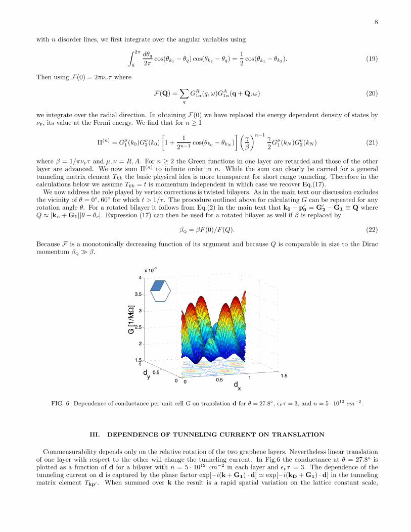
FIG. 6: Dependence of conductance per unit cell G on translation d for θ = 27.8, ǫFτ = 3, and n = 5 · 1012 cm−2.
III. DEPENDENCE OF TUNNELING CURRENT ON TRANSLATION
Commensurability depends only on the relative rotation of the two graphene layers. Nevertheless linear translationof one layer with respect to the other will change the tunneling current. In Fig.6 the conductance at θ = 27.8 isplotted as a function of d for a bilayer with n = 5 · 1012 cm−2 in each layer and ǫFτ = 3. The dependence of thetunneling current on d is captured by the phase factor exp[−i(k+G1) · d] ≃ exp[−i(kD +G1) · d] in the tunnelingmatrix element Tkp′ . When summed over k the result is a rapid spatial variation on the lattice constant scale,

9
illustrated in Fig.6 due to the exp[−i(kD +G1) · d] factor, modulated by a slower variation on the Fermi wavelengthscale.As illustrated in Fig.1 the conductance peaks appear symmetrically around θ = 30, but the height of a peak with
θ < 30 does not necessarily equal the height of the corresponding peak at θ′ = 60− θ. In fact, the relative height ofthe two peaks depends on d. An AA stacking sequence can be transformed to Bernal stacking either by a pure rotationwith θ = 60 or by a translation with d = (1, 0). Since the latter transformation does not influence commensurabilityany commensurate angle θc of the AA stacked bilayer is a commensurate angle of the Bernal stacked bilayer. Theconductance peaks then lie symmetrically with respect to θ = 30 since if θ is commensurate so is its inverse.
IV. CONDUCTANCE FOR COMMENSURATE ANGLES FOR d = 0.
For commensurate angles the conductance can be approximated by Eq.(4) in the main text. The integration overthe overlap of the two spectral functions
∑
k
A1(k, ǫF )A1(k, ǫF ) =A
2πv2[2 + 2πǫF τ + 4ǫF τ arctan (2ǫF τ)] (23)
is independent of the rotation angle and the entire dependence of G on the relative alignment of the two layers is inRµν(θ,d). We now evaluate R for d = 0.At the Dirac point the intra-layer Hamiltonian vanishes and we have contributions only from interlayer tunneling:
H0 =
(
0 TT † 0
)
(24)
where each element is a 2 × 2 block for the two π-bands in each layer. Using a representation of sublattice sites ineach layer we find that
T = T S =
(
2|a| 00 2|a| · e−2iφ
)
, T = T D =
(
2|a| 00 0
)
. (25)
Here T S and T D correspond respectively to intra-valley (S=same) and inter-valley (D=different) rotation angles asexplained in the main text, and φ = 0,±60 depends on θc: e.g. φ(0) = 0, φ(27.8) = 60 and φ(38.2) = −60. Ifthe hopping amplitude tq decreases fast enough with momentum so that only the first G-shell significantly contributeto the tunneling matrix
|a| = 1.5tkD+G1
Ω0(26)
where Ω0 is the area of a unit cell and G1 is the wavevector which produces the smallest q extended-zone Dirac-coneoverlap as explained in the text. In our model Eq.(26) is satisfied for all commensurate angles except for θ = 0, 60
for which |a| = 1.67tkD+G1/Ω0. Diagonalizing H0 yields ES = ±2|a| (both doubly degenerate) and ED = 0, 0,±2|a|.
In both cases the energy gap between the top conduction band and bottom valence band is therefore Eg = 4|a|.To find R we assume that T is well approximated by Eq.(25) for finite momentum states in the vicinity of the Dirac
points. We verified this assumption numerically for low densities. We first focus on inter-valley rotation angles. Inthe eigenstate representation
T µνkp′ = a1α⋆kµ a1βkνT
αβkp′ δkp′ . (27)
It follows from Eqs.(25,27) that
T D = ei(2θk+θc)|a|I. (28)
Consequently,
RDµν =
∫
dθk2π
|T µν(θk)|2 = |a|I (29)
and
GD(θc, d = 0) = Agvgse2
~
E2g(θc)
64π2v2[2 + 2πǫF τ + 4ǫF τ arctan (2ǫF τ)] . (30)
10
Expression (5) is obtained in the ǫFτ > 1 limit.Similarly for intra-valley rotation angles
T S = 2ei(φ+θc2)|a|
(
cos(
φ− θc2
)
−i sin(
φ− θc2
)
−i sin(
φ− θc2
)
cos(
φ− θc2
)
)
(31)
It then follows that
RS
µν =E2
g
4
(
cos2(
φ− θc2
)
sin2(
φ− θc2
)
sin2(
φ− θc2
)
cos2(
φ− θc2
)
)
(32)
and that the conductance is
GS(θc, d = 0) = Agvgse2
~
E2g(θc)
16π2v2cos2
(
φ− θc2
)
[2 + 2πǫF τ + 4ǫF τ arctan (2ǫF τ)] . (33)
Note that inter-band resonant conduction (which occurs when the carrier densities in the two layers are opposite)has the same form as its intra-band counterpart for inter-valley rotation angles. For the inter-band conduction atinter-valley rotation angles the cos function in Eq.(33) should be replaced by a sin. Interestingly, the ratio
∆G(θc) ≡GS(θc, d = 0)
GD(60 − θc, d = 0)= 4 cos2
(
φ− θc2
)
(34)
depends only on the twist angle. For example, ∆G(27.8) = 1.94 in accord with the numerical results depicted inFig.6.Using the momentum dependent T matrices we can find the bands in the vicinity of the Dirac points. For inter-valley
rotations we find four non-degenerate bands
ED
k = ±√
ǫ2k + 2|a|2 ± 2√
ǫ2k|a|2 + |a|4. (35)
At low energies ǫk ≪ a
ED
k1 = ± k2
2m⋆, ED
k2 = ±2|a| ± k2
2m⋆(36)
where m⋆ = |a|/v2. For the intra-layer rotations
ES
k = ±√
ǫ2k + 4|a|2 ± 4|a|ǫk cos (φ− θc/2) (37)
At low energies ǫk ≪ a
ES
k = ±2|a| ± v⋆k (38)
where v⋆ = v cos (φ− θc/2). Deviations from expressions (25) for T result in trigonal warping in a bilayer system.More elaborate studies of the spectrum are needed to determine whether such effects are important in a rotatedbilayer system as well.
[1] Castro Neto, A. H. et al. The electronic properties ofgraphene. Rev. Mod. Phys. 81, 109 (2009)
[2] Geim, A.K., & MacDonald, A.H. Graphene: Exploringcarbon flatland. Physics Today 60, 35-41 (2007).
[3] Chen, J. H., Jang, C., Xiao, S., Ishigami, M., &Fuhrer M. S. Intrinsic and extrinsic performance limits ofgraphene devices on SiO2. Nature Nanotech. 7, 206-209
(2008).[4] Lui, C. H., Liu L., Mak, K. F., Flynn, G. W., & Heinz,
T. F. Ultraflat graphene. Nature 462 339-341 (2009).[5] Sutter, P. W., Flege, J. I., & Sutter, E. A. Epitaxial
graphene on ruthenium. Nature Mater. 7 406-411 (2008).[6] Schmidt, H., Luedtke, T., arthold, P., & Haug, R.J.
Mobilities and Scattering Times in Decoupled Graphene

11
Monolayers. arXiv:0912.0278.[7] de Heer, W. A. et al. Epitaxial graphene Solid State Com-
munications 143, 92-100 (2007).[8] First, P. et al. Epitaxial Graphenes on Silicon Carbide.
MRS Bulliten, to appear April (2010).[9] Kim, K. S. et al. Large-scale pattern growth of graphene
films for stretchable transparent electrodes. Nature 457
706-710 (2009).[10] Kosynkin, D. V. et al.Longitudinal unzipping of carbon
nanotubes to form graphene nanoribbons. Nature 458
872-876 (2009).[11] Avouris, P., Chen, Z., & Perebeinos, V. Carbon-based
electronics. Nature nanotech. 2, 605-615 (2007).[12] Min, H.-K., & MacDonald, A.H. Chiral decomposition
in the electronic structure of graphene multilayers. Phys.Rev. B 77, 155416 (2008).
[13] Rong, Z. Y., & Kuiper, P. Electronic effects in scanningtunneling microscopy: Moire pattern on a graphite sur-face. Phys. Rev. B 48, 17427 (1993).
[14] Li, Guohong et al. Observation of Van Hove sin-gularities in twisted graphene layers, Nature Phys.doi:10.1038/nphys1463.
[15] Berger, C. et al. Ultrathin Epitaxial Graphite: 2D Elec-tron Gas Properties and a Route toward Graphene-basedNanoelectronics. J. Phys. Chem. B 108, 19912-19916(2004).
[16] Hass, J. et al. Why Multilayer Graphene on 4H-SiC(0001) Behaves Like a Single Sheet of Graphene. Phys.Rev. Lett. 100, 125504 (2008).
[17] Shallcross, S., Sharma, S., Kandelaki, E., & Pankra-tov, O. A. Electronic structure of turbostratic graphene.arXiv:0910.5811.
[18] Zhou, S. Y., Gweon, G.-H., & Lanzara, A. Low energyexcitations in graphite: the role of dimensionality andlattice defects. Ann. Phys.(N.Y.) 321, 1730-1746 (2006).
[19] Lopes dos Santos, J. M. B., Peres, N. M. R., & CastroNeto, A. H. Graphene Bilayer with a Twist: ElectronicStructure. Phys. Rev. Lett. 99, 256802 (2007).
[20] Shallcross, S., Sharma, S., & Pankratov, O. A. QuantumInterference at the Twist Boundary in Graphene. Phys.Rev. Lett. 101, 056803 (2008).
[21] E. McCann and V. I. Falko, Landau-Level Degeneracyand Quantum Hall Effect in a Graphite Bilayer. Phys.
Rev. Lett. 96, 086805 (2006).[22] P. Moses and R.H. McKenzie, Comparison of coherent
and weakly incoherent transport models for the interlayermagnetoresistance of layered Fermi liquids. Phys. Rev. B60, 7998 (1999).
[23] Zheng, L. & MacDonald, A. H. Tunneling conductancebetween parallel two-dimensional electron systems. Phys.Rev. B 47, 10619 (1993).
[24] L. Zheng and A. H. MacDonald, Tunneling ConductanceBetween Parallel 2-Dimensional Electron systems. Phys.Rev. B 47, 10619 (1993) and work cited therein.
[25] J.P. Eisenstein et al., Probing a 2-Dimensional Fermi-Surface by Tunneling. Phys. Rev. B 44, 6511 (1991) andwork cited therein.
[26] Miller, D. L. et al., Observing the Quantization of ZeroMass Carriers in Graphene, Science 324, 924-927 (2009).
[27] Lyo, S. K. Transport and level anticrossing in stronglycoupled double quantum wells with in plane magneticfields. Phys. Rev. B 50, 4965 (1994).
[28] Pereira, V. M., Castro Neto, A. H., & Peres, N. M. R.Tight-binding approach to uniaxial strain in graphene.Phys. Rev. B 80, 045401 (2009).
[29] A. B. Kuzmenko, I. Crassee, D. van der Marel, P.Blake, and K. S. Novoselov, Determination of the gate-tunable band gap and tight-binding parameters in bilayergraphene using infrared spectroscopy. Phys. Rev. B 80,165406 (2009).
[30] Lifshitz, R. What is a crystal? Z. Kristallogr. 222, 313-317 (2007).
[31] Schmidt, H., Ludtke, T., Barthold, P., & Haug R. J.Mobilities and Scattering Times in Decoupled GrapheneMonolayers. arXiv:0912.0278.
[32] Bonilla, L. L., & Grahn, H. T. Non-linear dynamics ofsemiconductor superlattices. Rep. Prog. Phys. 68, 577-683 (2005).
[33] Bunch J. S. et. al. Impermeable Atomic Membranes fromGraphene Sheets. Nano Lett., 8, 24582462 (2008).
[34] See for example W. A. Harrison, Elementary Electronic
Structure (World Scientific, Singapore, 1999).[35] Mahan, G. D., Many particle physics (Plenum press, New
York, 1990).