trends and innovations in high-rise structures
TRANSCRIPT
TRENDS AND INNOVATIONS IN HIGH-RISE STRUCTURES
by
Christopher D. Lubke
B.S. Civil EngineeringTexas Tech University
Submitted to the Department ofCivil and Environmental Engineering in
Partial Fulfillment of the Requirements for the Degree of
Master of Engineering inCivil and Environmental Engineering
at theMassachusetts Institute of Technology
June 2003
© 2003 Christopher D. Lubke. All rights reserved
MASSACHUSETTS INSTITUTEThe author hereby grants to MIT permission to reproduce OF TECHNOLOGY
and to distribute publicly paper and electroniccopies of this thesis document in whole or in part. JUN 0 2 2003
LIBRARIES
Signature of Author:Department of Civil and Environmental Engineering
May 12, 2003
Certified by:Jerome Connor
Professor of Civil and Environmental EngineeringThesis Supervisor
Accepted by:FF
A e p e b y O r a l B u y u k o z tu r kProfessor of Civil and Environmental Engineering
Chairman, Departmental Committee on Graduate Studies
TRENDS AND INNOVATIONS IN HIGH-RISE STRUCTURES
by
Christopher D. Lubke
Submitted to the Department of Civil andEnvironmental Engineering on May 12, 2003 in
Partial Fulfillment of the Degree Requirements forMaster of Engineering in Civil and Environmental Engineering
ABSTRACT
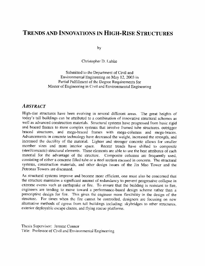
High-rise structures have been evolving in several different areas. The great heights oftoday's tall buildings can be attributed to a combination of innovative structural schemes aswell as advanced construction materials. Structural systems have progressed from basic rigidand braced frames to more complex systems that involve framed tube structures, outriggerbraced structures, and mega-braced frames with mega-columns and mega-braces.Advancements in concrete technology have decreased the weight, increased the strength, andincreased the ductility of the material. Lighter and stronger concrete allows for smallermember sizes and more interior space. Recent trends have shifted to composite(steel/concrete) structural elements. These elements are able to use the best attributes of eachmaterial for the advantage of the structure. Composite columns are frequently used,consisting of either a concrete filled tube or a steel section encased in concrete. The structuralsystems, construction materials, and other design issues of the Jin Mao Tower and thePetronas Towers are discussed.
As structural systems improve and become more efficient, one must also be concerned thatthe structure maintains a significant amount of redundancy to prevent progressive collapse inextreme events such as earthquake or fire. To ensure that the building is resistant to fire,engineers are tending to move toward a performance-based design scheme rather than aprescriptive design for fire. This gives the engineer more flexibility in the design of thestructure. For times when the fire cannot be controlled, designers are focusing on newalternative methods of egress from tall buildings including: skybridges to other structures,exterior deployable escape chutes, and flying rescue platforms.
Thesis Supervisor: Jerome ConnorTitle: Professor of Civil and Environmental Engineering
ACKNOWLEDGMENTSI would like to express my appreciation to the Department of Civil and EnvironmentalEngineering. The academic fellowship that was granted to me by the department made myattendance at MIT possible. The excellent faculty and staff helped to make my experiencehere a very rewarding educational experience.
The people that I appreciate the most, who have been right there beside me through it all, aremy fellow M. Eng. students. You helped me work through the difficult times and enjoy thegood times. The friendships that I have made will carry on for years to come.
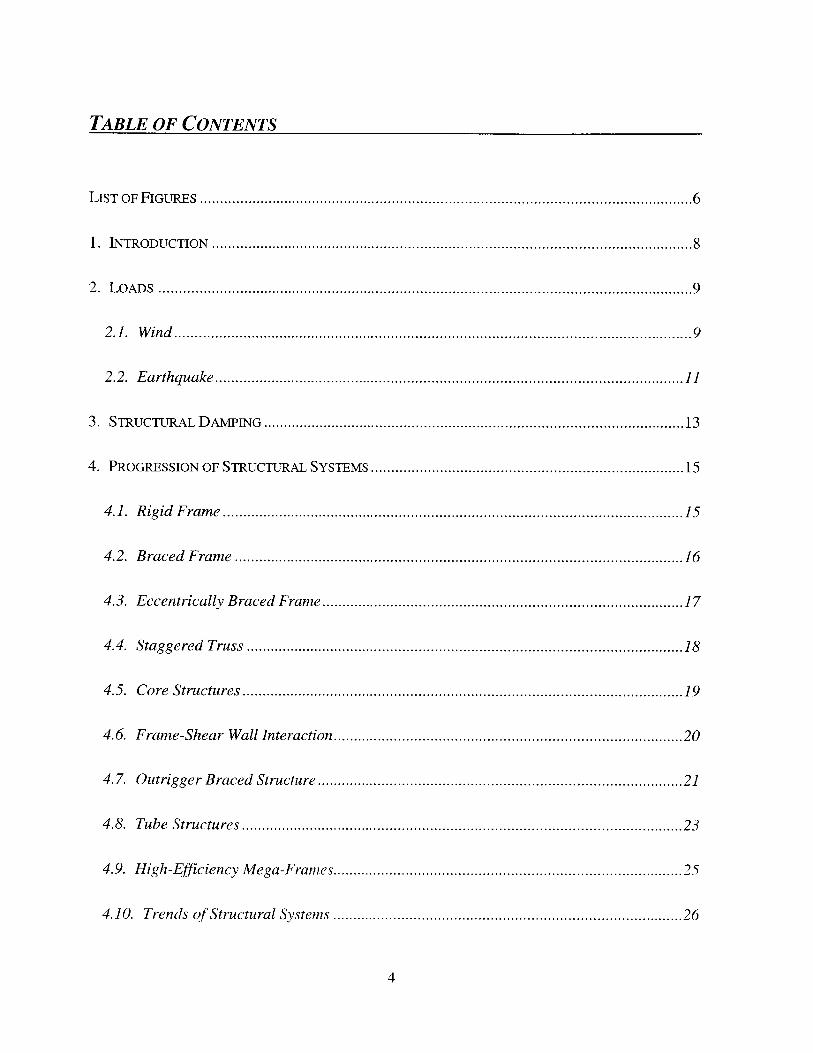
TABLE OF CONTENTS
LIST OF FIGURES .......................................................................................................................... 6
1. INTRODUCTION ....................................................................................................................... 8
2 . L o A D s .................................................................................................................................... 9
2 .1 . W in d ................................................................................................................................ 9
2.2. Earthquake .................................................................................................................... 11
3. STRUCTURAL DAMTING ........................................................................................................ 13
4. PROGRESSION OF STRUCTURAL SYSTEMS ............................................................................. 15
4. 1. Rigid Frame .................................................................................................................. 15
4.2. Braced Frame ............................................................................................................... 16
4.3. Eccentrically Braced Frame ......................................................................................... 17
4.4. Staggered Truss ............................................................................................................ 18
4.5. Core Structures ............................................................................................................. 19
4.6. Frame-Shear Wall Interaction ...................................................................................... 20
4.7. Outrigger Braced Structure .......................................................................................... 21
4.8. Tube Structures ............................................................................................................. 23
4.9. H igh-Efficiency M ega-Frames ...................................................................................... 25
4.10. Trends of Structural Systems ...................................................................................... 26
4
TABLE OF CONTENTS (CONT.)
5. ADVANCEMENTS OF M ATERIALS ....................................................................................... 28
6. EFF CENCY VS. REDUNDANCY ............................................................................................. 33
7. PERFORMANCE-BASED D ESIGN FOR FIRE .......................................................................... 35
8. EM ERGENCY EGRESS ............................................................................................................ 39
9. CASE STUDIES.......................................................................................................................42
9.1. Petronas Towers, Kuala Lumpur, Malasia .............................. 42
9.2. Jin Mao Tower, Shanghai, China .................................... 43
10. CONCLUSION.......................................................................................................................46
A l. REFERENCES ...................................................................................................................... 47
5
LIST OF FIGURES
Figure 1. Schematic of Wind Loading on a Structure. .......................................................... 9
Figure 2. Effect of Vortex Shedding on a High-Rise Structure .......................................... 10
Figure 3. Shear Racking of a Rigid Frame..........................................................................16
Figure 4. Behavior of a Braced Frame................................................................................ 17
Figure 5. Behavior of Eccentrically Braced Frame. .......................................................... 18
Figure 6. Staggered Truss System . ....................................................................................... 19
Figure 7. Schematic of Core Supported Structure................................................................20
Figure 8. Behavior of Shear Wall-Frame Interaction. ........................................................ 21
Figure 9. Behavior of Outrigger Braced Structure Under Load.........................................22
Figure 10. Model of Simplified Structure With Outrigger Bracing................................... 23
Figure 11. Plan View of Tube Structure. ............................................................................. 24
Figure 12. Illustration of the Effects of Shear Lag. ............................................................ 24
Figure 13. Schematic of Tube Structures............................................................................ 25
Figure 14. High Efficiency Structure.................................................................................. 26
Figure 15. Maximum Height of Concrete Structural Systems (Ali, 2001)...........................27
F igure 16. Tallest 200 B uildings. ....................................................................................... 28
Figure 17. Tallest 200 Buildings by Decade ....................................................................... 29
6
LIST OF FIGURES (CONT.)
Figure 18. Height of 200 Tallest Buildings. ........................................................................ 30
Figure 19. Static Redundancy Under Earthquake Ground Motion....................................34
Figure 20. Deformations of a Frame Structure Created by an Isolated Fire......................37
Figure 21. Photograph of Petronas Towers (Bocaling, 2000). ........................................... 42
Figure 22. Photograph of the Jin Mao Tower (Shanghai, 2003). ....................................... 44
7
TRENDS AND INNOVATIONS IN HIGH-RISE STRUCTURESBY CHRISTOPHER D. LUBKE
1. INTRODUCTION
Since the square footage of land is very limited in an urban environment, high-rise
structures are a highly efficient scheme of maximizing the use of one particular land area.
The taller that a building is, the more revenue can be generated from that area. Therefore
designers are continually pushing the limits of the height of buildings and the amount of
usable space inside the structure.
One method of increasing the height of the building is to improve the structural
systems to resist the loads acting on the system more efficiently. Recent designs have
involved the use of mega-braced frames that rely on a few very large members to resist a
majority of the loads. But, with a fewer number of members, the structures may become less
redundant and more vulnerable to unexpected events. Recent studies have been conducted in
evaluating the vulnerability of structures.
Another way to extend structures to new heights is to improve the properties of the
materials that are used to construct the structure. Many buildings are combining steel and
concrete throughout the structure to utilize the most attractive aspects of each material.
New consideration is being given to the issue of fire safety in high-rise buildings.
Recent trends are moving away from the prescriptive-base fire design to comprehensive
performance-based design in order to give the engineer more flexibility in the building design.
New technologies are also evolving to improve the method of egress from tall buildings.
8
2. LOADS
There are two types of loading on any structure: gravity loads and lateral loads. The
gravity loads are the same for a high-rise and low-rise structure except high-rise buildings
accumulate much more load near the bottom of the structure. Lateral loads, including wind
and earthquake, are generally the critical issue associated with tall buildings.
2.1. WIND
Wind loads become a critical element associated with tall buildings. Because it acts as
a pressure, a large force is exerted on the large building surface. The intensity of the pressure
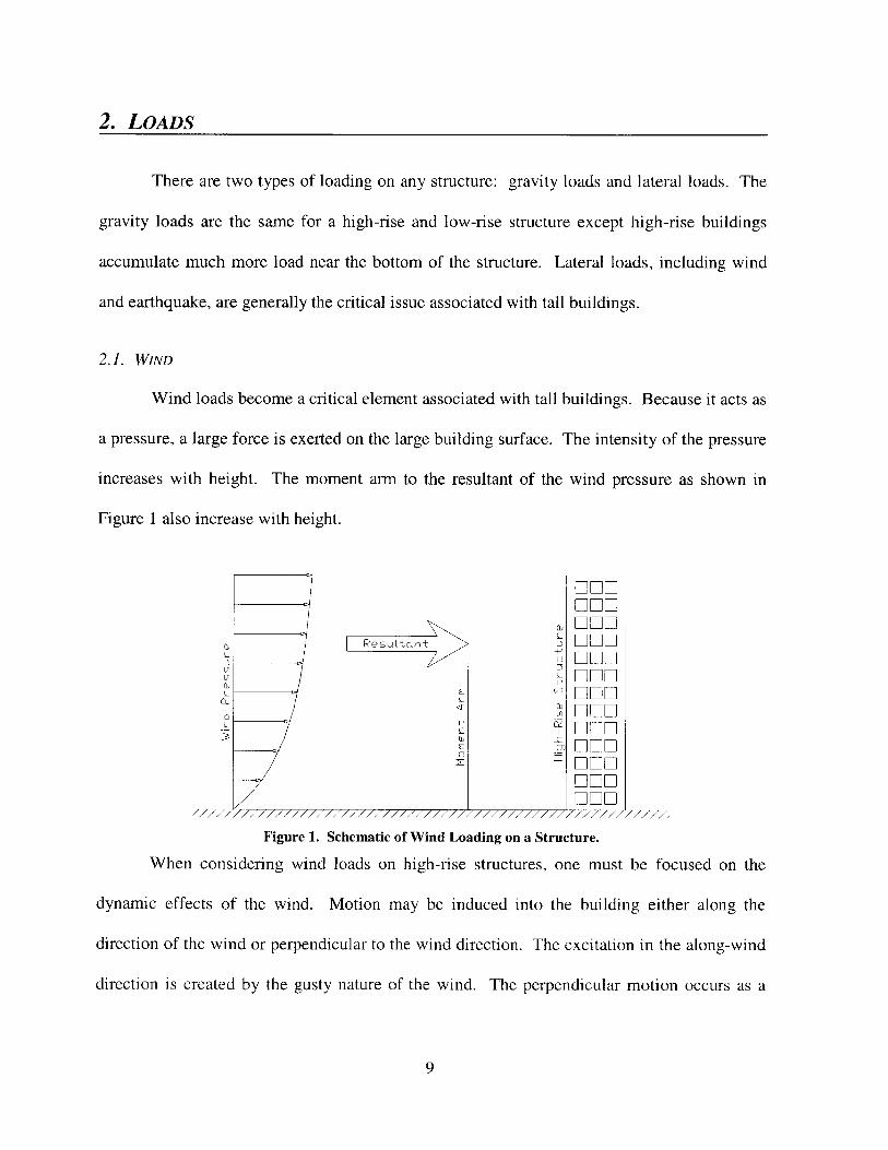
increases with height. The moment arm to the resultant of the wind pressure as shown in
Figure 1 also increase with height.
ant ~ ~ DE -
E (/ n DD
a)i
7777-1111111111111111//1//////1//// / /7/71/71//777771/'777:7
Figure 1. Schematic of Wind Loading on a Structure.
When considering wind loads on high-rise structures, one must be focused on the
dynamic effects of the wind. Motion may be induced into the building either along the
direction of the wind or perpendicular to the wind direction. The excitation in the along-wind
direction is created by the gusty nature of the wind. The perpendicular motion occurs as a
9
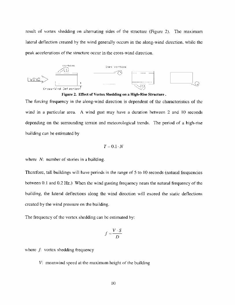
result of vortex shedding on alternating sides of the structure (Figure 2). The maximum
lateral deflection created by the wind generally occurs in the along-wind direction, while the
peak accelerations of the structure occur in the cross-wind direction.
Vortices Shed Vortices
\WIND E=LL
Cross-Wino Def~ectior7
Figure 2. Effect of Vortex Shedding on a High-Rise Structure.
The forcing frequency in the along-wind direction is dependent of the characteristics of the
wind in a particular area. A wind gust may have a duration between 2 and 10 seconds
depending on the surrounding terrain and meteorological trends. The period of a high-rise
building can be estimated by
T =0.1 -N
where N: number of stories in a building.
Therefore, tall buildings will have periods in the range of 5 to 10 seconds (natural frequencies
between 0.1 and 0.2 Hz.) When the wind gusting frequency nears the natural frequency of the
building, the lateral deflections along the wind direction will exceed the static deflections
created by the wind pressure on the building.
The frequency of the vortex shedding can be estimated by:
V -S
D
where f: vortex shedding frequency
V: meanwind speed at the maximum height of the building
10
S: Strouhal number (shape and velocity dependent)
D: diameter of the structure.
When the forcing frequency of the vortex shedding approaches the transverse natural
frequency of a building, excessive lateral crosswind deformations may occur, if the structure
does not have any significant amount of structural damping. After the structure begins to
resonate with the vortices, the forcing frequency tends to "lock-on" to the transverse natural
frequency of the structure. Therefore, small changes (±10%) in the wind velocity will not
change the behavior of the vortex shedding phenomenon. The vortices will continue to shed
corresponding to the oscillations of the structure until the wind velocity has changed beyond
the "lock-on" range.
Since the frequency of vortex shedding phenomenon is critical for range of values near
the transverse natural frequency of the structure the approximation of the forcing frequency
does not have to be extremely precise. This important to a designer since high-rise buildings
are generally complex shapes, and the Strouhal number must be determined experimentally.
2.2. EARTHQUAKE
Earthquakes are able to damage a structure not by a direct force as with wind or
gravity loads, but by intense vibration. As the building vibrates, inertial forces are developed
within the structure simply because there is mass in the structure. Therefore the more mass
that a building has, the more susceptible it is to damage cause by an earthquake. Another
problem associated with earthquakes is the nonlinear, P-A, effects on vertical elements such as
columns and walls. When these elements are push out of plumb by the lateral ground motion,
they become unstable under vertical loading and more susceptible to buckling.
11
Earthquakes produce a spectrum of accelerations that are transferred through the soil.
For analysis of the structure, one wants to generate a response spectrum of a given design
earthquake. The response spectrum shows the maximum response of a damped single-degree
of-freedom mass-spring system with respect to the natural period of the system. The response
can either be the absolute acceleration, pseudo relative velocity, or relative displacement of
the structures. All three characteristics can be represented on a tripartite logarithmic plot.
When performing an earthquake resistant design, it is not necessary to limit the
amount of acceleration for human comfort. The goal is to minimize the amount of lateral drift
to prevent yielding and buckling of structural members and distress in architectural
components such as interior partitions or window glazing.
Since some amount of lateral drift is inevitable during an earthquake, a designer will
want to make a structure as ductile as possible. Ductility allows a structure to undergo
inelastic deformation without creating a failure or collapse. Concrete is typically a very brittle
material, but with proper reinforcement, it can endure large deflections before failure.
Earthquake loads exerted on a structure can either be determined statically by an
equivalent force method or dynamically. The 1994 Uniform Building Code requires a
dynamic analysis for tall buildings (over 240 ft) in order to evaluate the effects of vibration
modes above the first mode. To see the effects of the higher modes, it is necessary to model
the structure as a multi-degree of freedom system. This can be accomplished by lumping the
mass of the structure at discrete levels corresponding to the floor levels of the building. Then
the response of the structure can be analyzed for a particular ground motion depending of the
stiffness and damping properties of the structure.
12
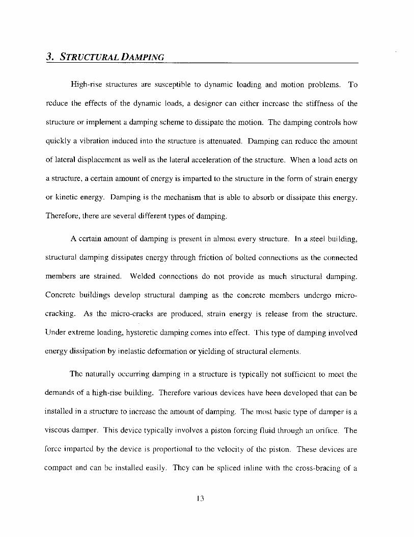
3. STRUCTURAL DAMPING
High-rise structures are susceptible to dynamic loading and motion problems. To
reduce the effects of the dynamic loads, a designer can either increase the stiffness of the
structure or implement a damping scheme to dissipate the motion. The damping controls how
quickly a vibration induced into the structure is attenuated. Damping can reduce the amount
of lateral displacement as well as the lateral acceleration of the structure. When a load acts on
a structure, a certain amount of energy is imparted to the structure in the form of strain energy
or kinetic energy. Damping is the mechanism that is able to absorb or dissipate this energy.
Therefore, there are several different types of damping.
A certain amount of damping is present in almost every structure. In a steel building,
structural damping dissipates energy through friction of bolted connections as the connected
members are strained. Welded connections do not provide as much structural damping.
Concrete buildings develop structural damping as the concrete members undergo micro-
cracking. As the micro-cracks are produced, strain energy is release from the structure.
Under extreme loading, hysteretic damping comes into effect. This type of damping involved
energy dissipation by inelastic deformation or yielding of structural elements.
The naturally occurring damping in a structure is typically not sufficient to meet the
demands of a high-rise building. Therefore various devices have been developed that can be
installed in a structure to increase the amount of damping. The most basic type of damper is a
viscous damper. This device typically involves a piston forcing fluid through an orifice. The
force imparted by the device is proportional to the velocity of the piston. These devices are
compact and can be installed easily. They can be spliced inline with the cross-bracing of a
13
braced frame structure. As the structure tries to rack, the bracing will be extended and the
damper will be actuated.
Other devices can be put in place to utilize hysteretic damping. The objective of these
devices is to yield under intense loading before the structure yields. Once the hysteretic
damper begins yielding under intense cyclic load such as an earthquake, energy will be
dissipated. The dampers may consist of a ductile steel core that is surrounded by a larger
jacket to increase the bending rigidity. The bending rigidity allows the device to function in
tension and compression (Connor, 2003).
Engineers have also been able to implement damping devices in structures that are
"tuned" to the natural frequency of the individual structure. These tuned mass dampers
(TMD) involve a large mass that is allowed to move with respect to the structure. The a
translational TMD travels on tracks and roller, and a pendulum TMD is simply a mass
suspended by a series of cables or rods to form a pendulum. The translational TMD is
connected to a spring and damper system that controls the tuned frequency of the device. The
frequency of the pendulum damper is modified by selecting the appropriate length of the
pendulum.
TMD can be implemented with a new design or used to retrofit buildings that develop
unexpected motion problems. One problem of these devices is that they often occupy large
amounts of space in a building. TMD have been implemented to reduce motion problems in
the John Hancock Tower in Boston, the Citicorp Center in Manhattan, and the Crystal Tower
in Osaka just to name a few.
14
4. PROGRESSION OF STRUCTURAL SYSTEMS
The maximum height of a building is simply governed by the ability of the structure to
resist the loads that are acting on it as discussed in the previous section. The method that is
used to resist these forces is dependent on the distribution of structural members as well as the
properties of the members themselves. Structural systems and material properties are
continually evolving in order to more efficiently resist the loads acting on the structure and
maximum the amount of usable space inside the building.
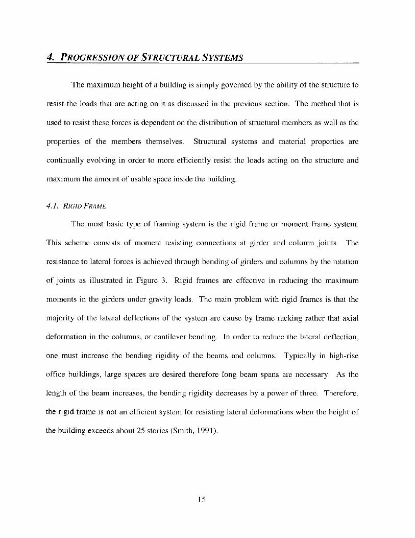
4.1. RIGID FRAME
The most basic type of framing system is the rigid frame or moment frame system.
This scheme consists of moment resisting connections at girder and column joints. The
resistance to lateral forces is achieved through bending of girders and columns by the rotation
of joints as illustrated in Figure 3. Rigid frames are effective in reducing the maximum
moments in the girders under gravity loads. The main problem with rigid frames is that the
majority of the lateral deflections of the system are cause by frame racking rather that axial
deformation in the columns, or cantilever bending. In order to reduce the lateral deflection,
one must increase the bending rigidity of the beams and columns. Typically in high-rise
office buildings, large spaces are desired therefore long beam spans are necessary. As the
length of the beam increases, the bending rigidity decreases by a power of three. Therefore,
the rigid frame is not an efficient system for resisting lateral deformations when the height of
the building exceeds about 25 stories (Smith, 1991).
15
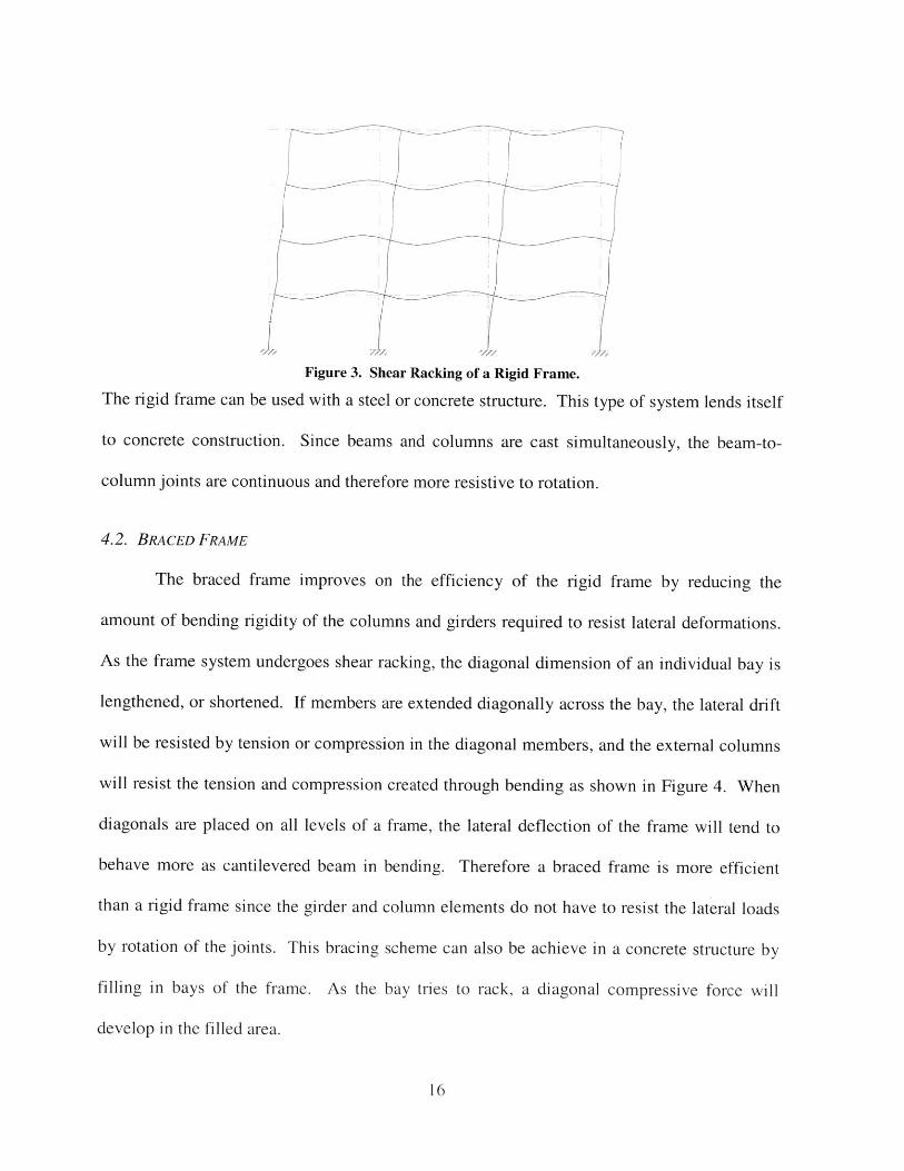
Figure 3. Shear Racking of a Rigid Frame.
The rigid frame can be used with a steel or concrete structure. This type of system lends itself
to concrete construction. Since beams and columns are cast simultaneously, the beam-to-
column joints are continuous and therefore more resistive to rotation.
4.2. BRACED FRAME
The braced frame improves on the efficiency of the rigid frame by reducing the
amount of bending rigidity of the columns and girders required to resist lateral deformations.
As the frame system undergoes shear racking, the diagonal dimension of an individual bay is
lengthened, or shortened. If members are extended diagonally across the bay, the lateral drift
will be resisted by tension or compression in the diagonal members, and the external columns
will resist the tension and compression created through bending as shown in Figure 4. When
diagonals are placed on all levels of a frame, the lateral deflection of the frame will tend to
behave more as cantilevered beam in bending. Therefore a braced frame is more efficient
than a rigid frame since the girder and column elements do not have to resist the lateral loads
by rotation of the joints. This bracing scheme can also be achieve in a concrete structure by
filling in bays of the frame. As the bay tries to rack, a diagonal compressive force will
develop in the filled area.
16
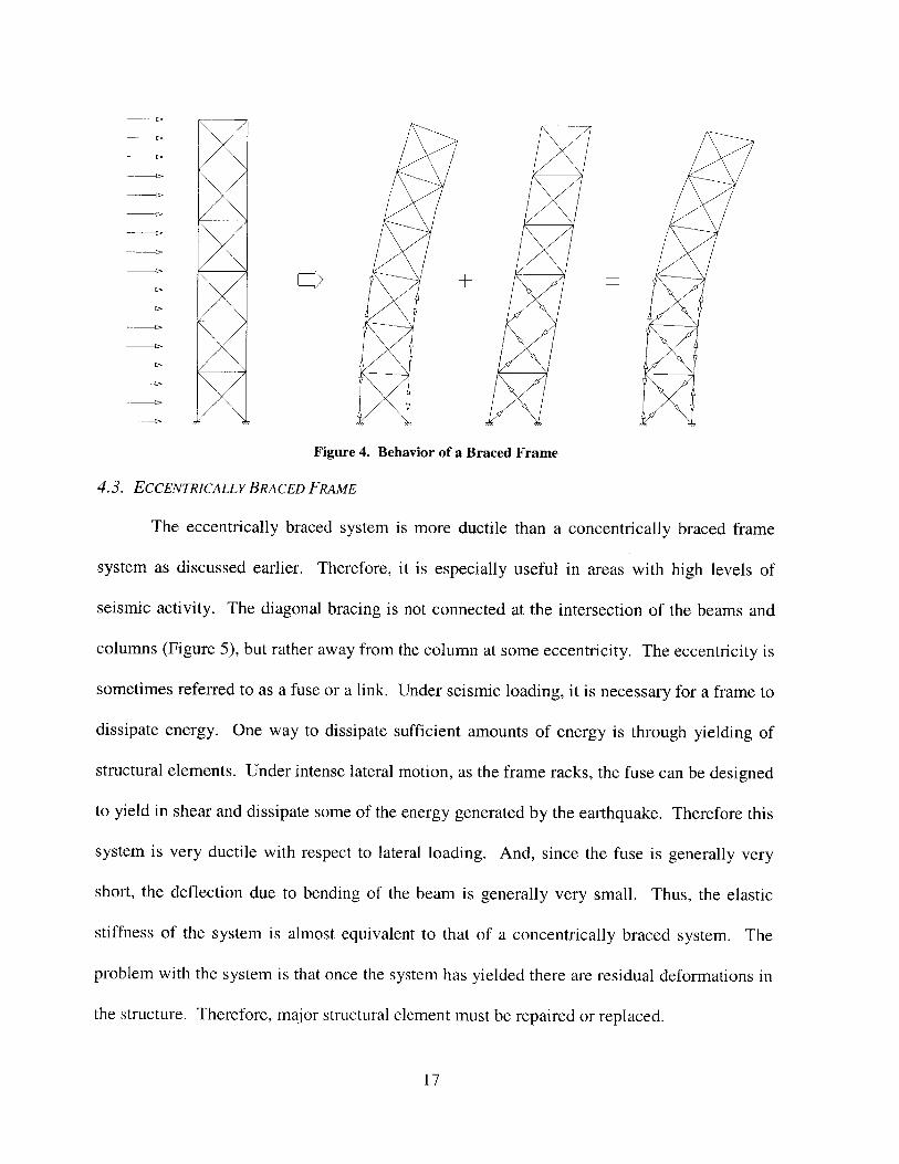
Figure 4. Behavior of a Braced Frame
4.3. ECCENTRICALLY BRACED FRAME
The eccentrically braced system is more ductile than a concentrically braced frame
system as discussed earlier. Therefore, it is especially useful in areas with high levels of
seismic activity. The diagonal bracing is not connected at the intersection of the beams and
columns (Figure 5), but rather away from the column at some eccentricity. The eccentricity is
sometimes referred to as a fuse or a link. Under seismic loading, it is necessary for a frame to
dissipate energy. One way to dissipate sufficient amounts of energy is through yielding of
structural elements. Under intense lateral motion, as the frame racks, the fuse can be designed
to yield in shear and dissipate some of the energy generated by the earthquake. Therefore this
system is very ductile with respect to lateral loading. And, since the fuse is generally very
short, the deflection due to bending of the beam is generally very small. Thus, the elastic
stiffness of the system is almost equivalent to that of a concentrically braced system. The
problem with the system is that once the system has yielded there are residual deformations in
the structure. Therefore, major structural element must be repaired or replaced.
17
Eccentricity
Pastic Hinges
Figure 5. Behavior of Eccentrically Braced Frame.
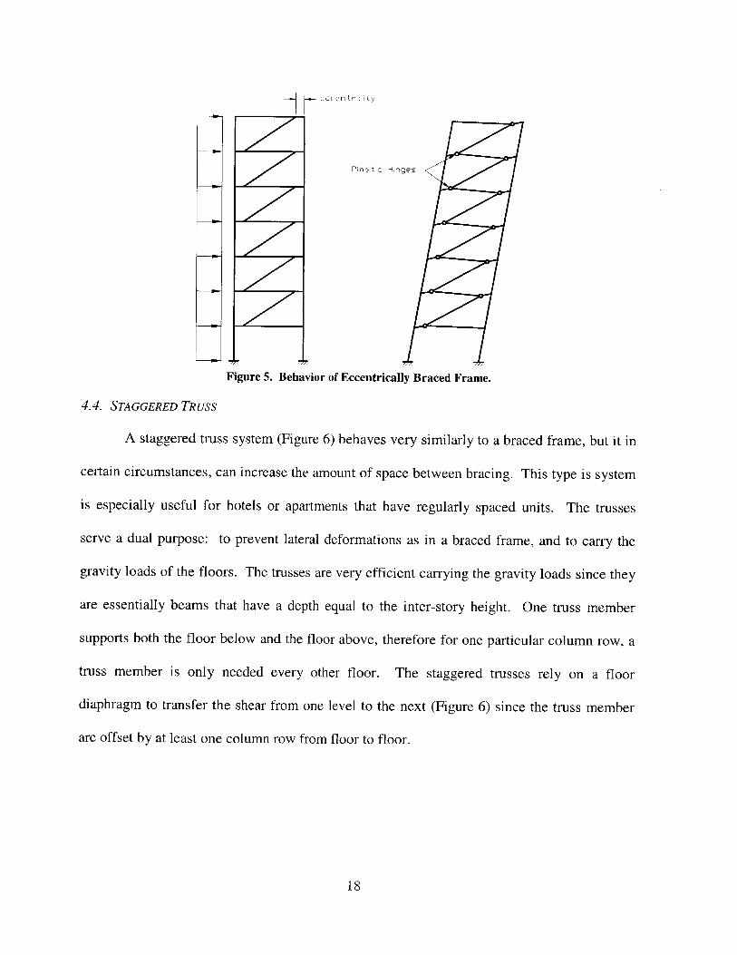
4.4. STAGGERED TRUSS
A staggered truss system (Figure 6) behaves very similarly to a braced frame, but it in
certain circumstances, can increase the amount of space between bracing. This type is system
is especially useful for hotels or apartments that have regularly spaced units. The trusses
serve a dual purpose: to prevent lateral deformations as in a braced frame, and to carry the
gravity loads of the floors. The trusses are very efficient carrying the gravity loads since they
are essentially beams that have a depth equal to the inter-story height. One truss member
supports both the floor below and the floor above, therefore for one particular column row, a
truss member is only needed every other floor. The staggered trusses rely on a floor
diaphragm to transfer the shear from one level to the next (Figure 6) since the truss member
are offset by at least one column row from floor to floor.
18
oil.
Figure 6. Staggered Truss System.
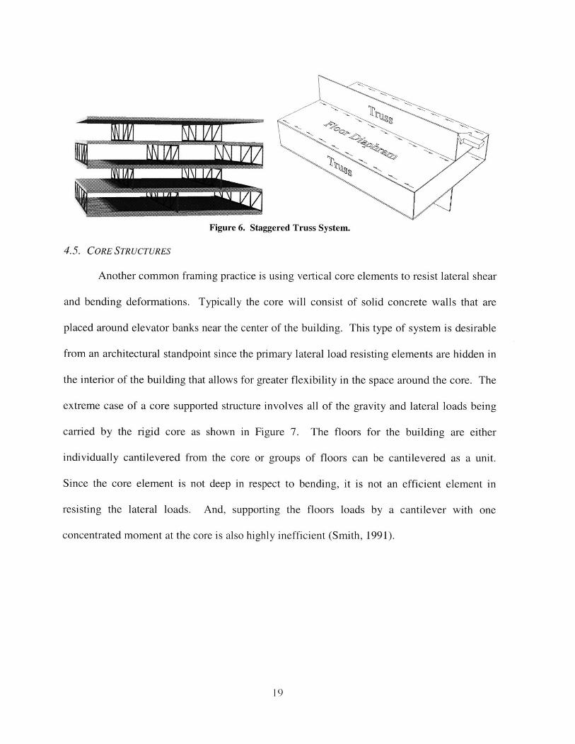
4.5. CORE STRUCTURES
Another common framing practice is using vertical core elements to resist lateral shear
and bending deformations. Typically the core will consist of solid concrete walls that are
placed around elevator banks near the center of the building. This type of system is desirable
from an architectural standpoint since the primary lateral load resisting elements are hidden in
the interior of the building that allows for greater flexibility in the space around the core. The
extreme case of a core supported structure involves all of the gravity and lateral loads being
carried by the rigid core as shown in Figure 7. The floors for the building are either
individually cantilevered from the core or groups of floors can be cantilevered as a unit.
Since the core element is not deep in respect to bending, it is not an efficient element in
resisting the lateral loads. And, supporting the floors loads by a cantilever with one
concentrated moment at the core is also highly inefficient (Smith, 1991).
19
CantileverSupports
w~1 1~
____ I __ I ____
____ .1 __ I ____
____ II __ I ____
II
Indiv duallyCantiLeveredFloors
Cr oup-CantileveredFloors
Core
Figure 7. Schematic of Core Supported Structure.
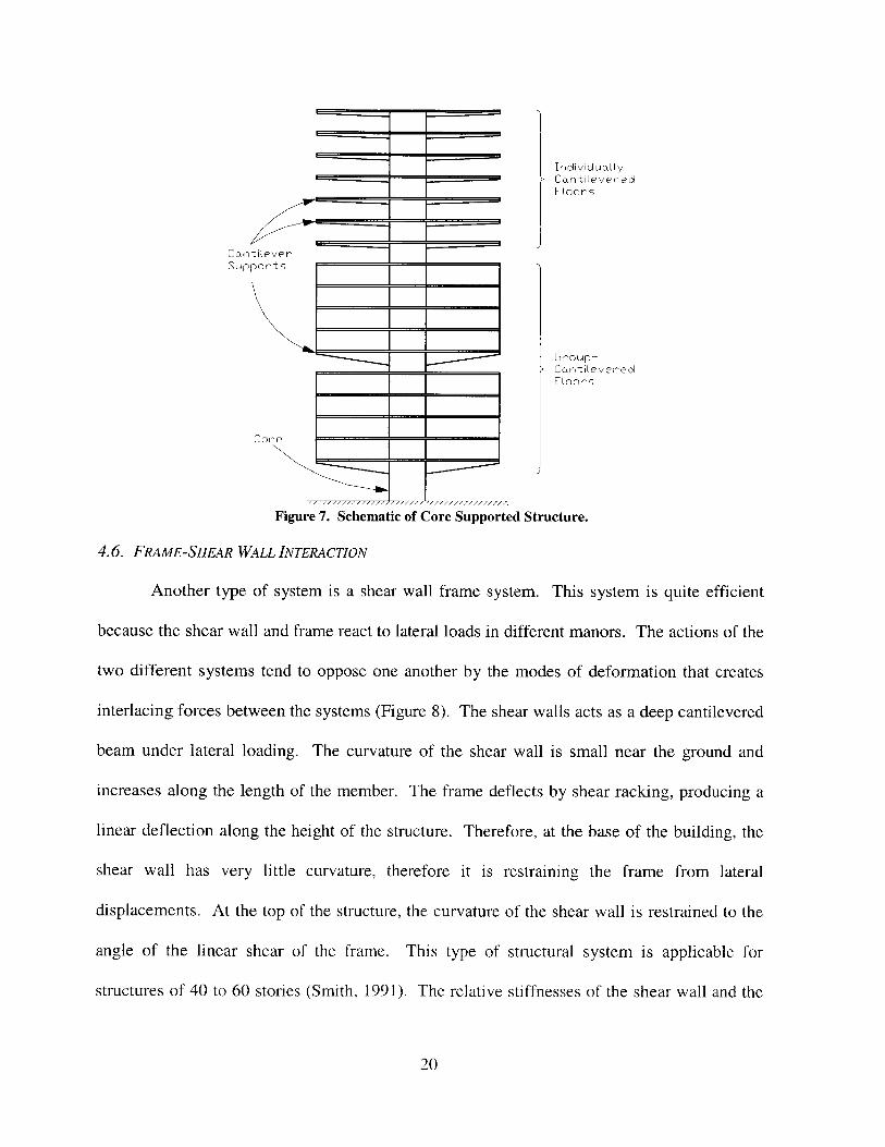
4.6. FRAME-SHEAR WALL INTERACTION
Another type of system is a shear wall frame system. This system is quite efficient
because the shear wall and frame react to lateral loads in different manors. The actions of the
two different systems tend to oppose one another by the modes of deformation that creates
interlacing forces between the systems (Figure 8). The shear walls acts as a deep cantilevered
beam under lateral loading. The curvature of the shear wall is small near the ground and
increases along the length of the member. The frame deflects by shear racking, producing a
linear deflection along the height of the structure. Therefore, at the base of the building, the
shear wall has very little curvature, therefore it is restraining the frame from lateral
displacements. At the top of the structure, the curvature of the shear wall is restrained to the
angle of the linear shear of the frame. This type of structural system is applicable for
structures of 40 to 60 stories (Smith, 1991). The relative stiffnesses of the shear wall and the
20
____ I __ I ____
4=
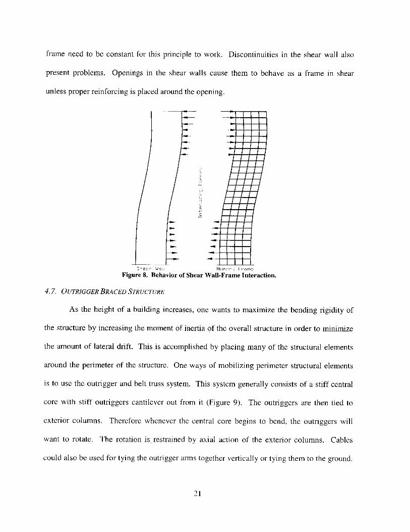
frame need to be constant for this principle to work. Discontinuities in the shear wall also
present problems. Openings in the shear walls cause them to behave as a frame in shear
unless proper reinforcing is placed around the opening.
ULa
0)
Shear Walt Moment Frame
Figure 8. Behavior of Shear Wall-Frame Interaction.
4.7. OUTRIGGER BRACED STRUCTURE
As the height of a building increases, one wants to maximize the bending rigidity of
the structure by increasing the moment of inertia of the overall structure in order to minimize
the amount of lateral drift. This is accomplished by placing many of the structural elements
around the perimeter of the structure. One ways of mobilizing perimeter structural elements
is to use the outrigger and belt truss system. This system generally consists of a stiff central
core with stiff outriggers cantilever out from it (Figure 9). The outriggers are then tied to
exterior columns. Therefore whenever the central core begins to bend, the outriggers will
want to rotate. The rotation is restrained by axial action of the exterior columns. Cables
could also be used for tying the outrigger arms together vertically or tying them to the ground.
21
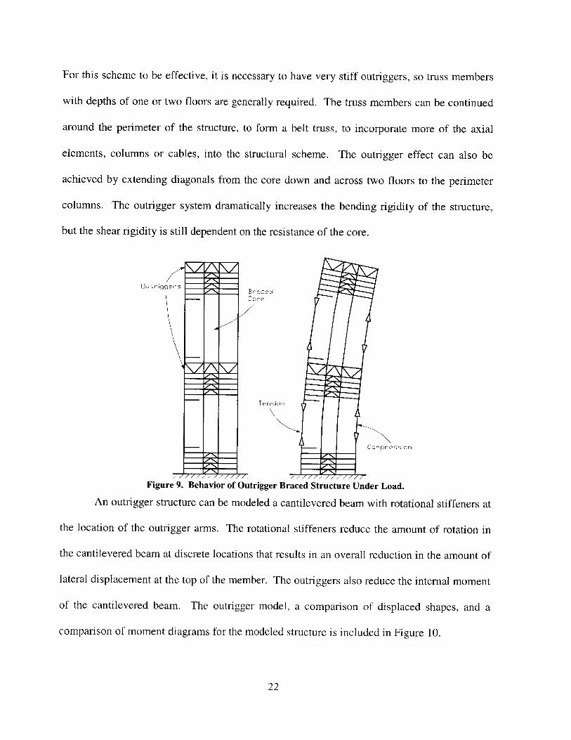
For this scheme to be effective, it is necessary to have very stiff outriggers, so truss members
with depths of one or two floors are generally required. The truss members can be continued
around the perimeter of the structure, to form a belt truss, to incorporate more of the axial
elements, columns or cables, into the structural scheme. The outrigger effect can also be
achieved by extending diagonals from the core down and across two floors to the perimeter
columns. The outrigger system dramatically increases the bending rigidity of the structure,
but the shear rigidity is still dependent on the resistance of the core.
Elutriggers BracedCore
Tension
Compression
7 777 777'77777-7Figure 9. Behavior of Outrigger Braced Structure Under Load.
An outrigger structure can be modeled a cantilevered beam with rotational stiffeners at
the location of the outrigger arms. The rotational stiffeners reduce the amount of rotation in
the cantilevered beam at discrete locations that results in an overall reduction in the amount of
lateral displacement at the top of the member. The outriggers also reduce the internal moment
of the cantilevered beam. The outrigger model, a comparison of displaced shapes, and a
comparison of moment diagrams for the modeled structure is included in Figure 10.
22
Outriggers
withoutOutriggers
\WithoutOutriggers
Outriggers
Model of Structure with Deflected Shape Moment DiagramOutriggers and a Uniform Load
Figure 10. Model of Simplified Structure With Outrigger Bracing.
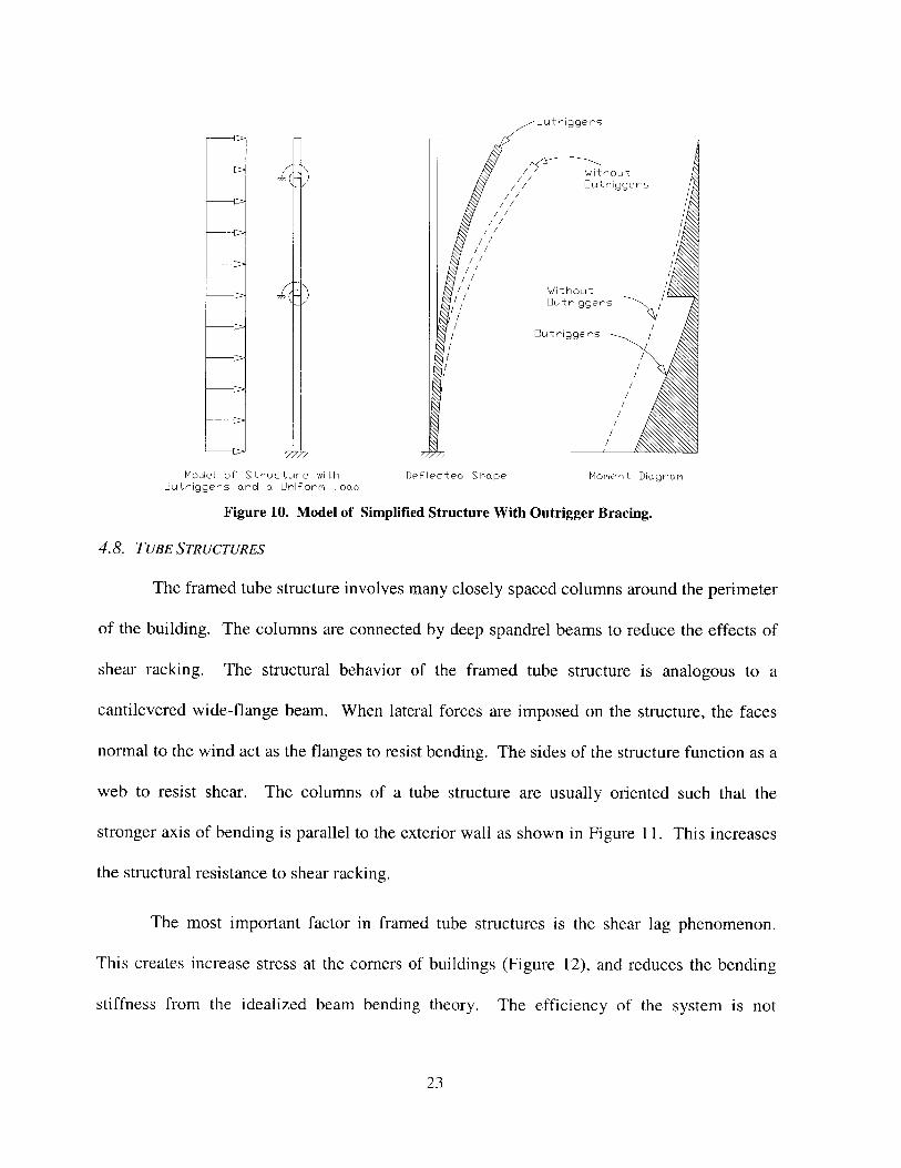
4.8. TUBE STRUCTURES
The framed tube structure involves many closely spaced columns around the perimeter
of the building. The columns are connected by deep spandrel beams to reduce the effects of
shear racking. The structural behavior of the framed tube structure is analogous to a
cantilevered wide-flange beam. When lateral forces are imposed on the structure, the faces
normal to the wind act as the flanges to resist bending. The sides of the structure function as a
web to resist shear. The columns of a tube structure are usually oriented such that the
stronger axis of bending is parallel to the exterior wall as shown in Figure 11. This increases
the structural resistance to shear racking.
The most important factor in framed tube structures is the shear lag phenomenon.
This creates increase stress at the corners of buildings (Figure 12), and reduces the bending
stiffness from the idealized beam bending theory. The efficiency of the system is not
23
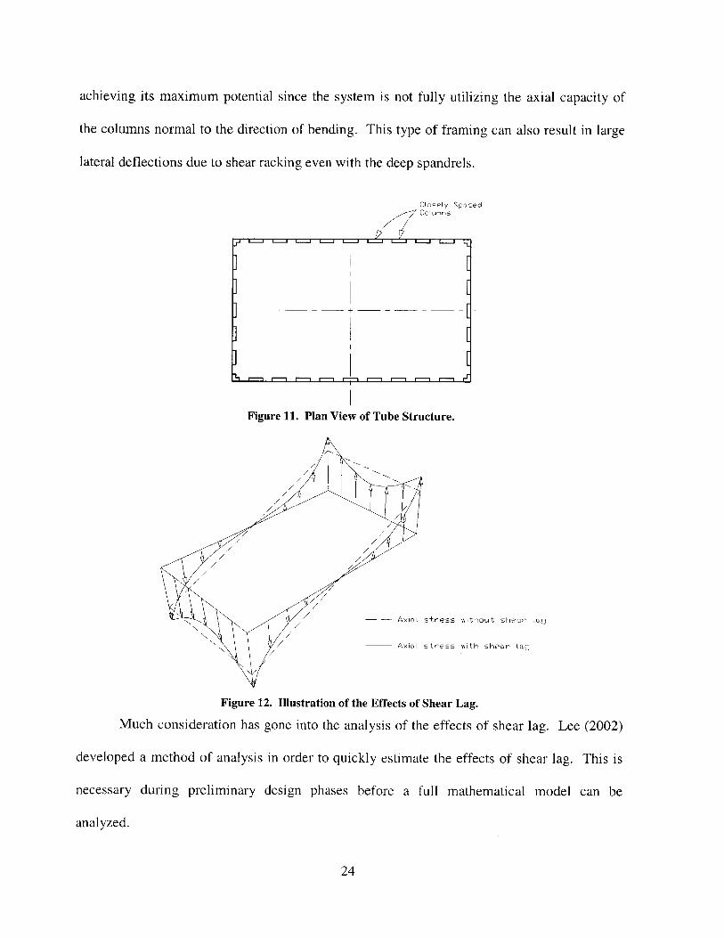
achieving its maximum potential since the system is not fully utilizing the axial capacity of
the columns normal to the direction of bending. This type of framing can also result in large
lateral deflections due to shear racking even with the deep spandrels.
Closely SpacedColurmns
Figure 11. Plan View of Tube Structure.
Axial stress without shear Lag
____Axiai stress with shear Lag
Figure 12. Illustration of the Effects of Shear Lag.
Much consideration has gone into the analysis of the effects of shear lag. Lee (2002)
developed a method of analysis in order to quickly estimate the effects of shear lag. This is
necessary during preliminary design phases before a full mathematical model can be
analyzed.
24
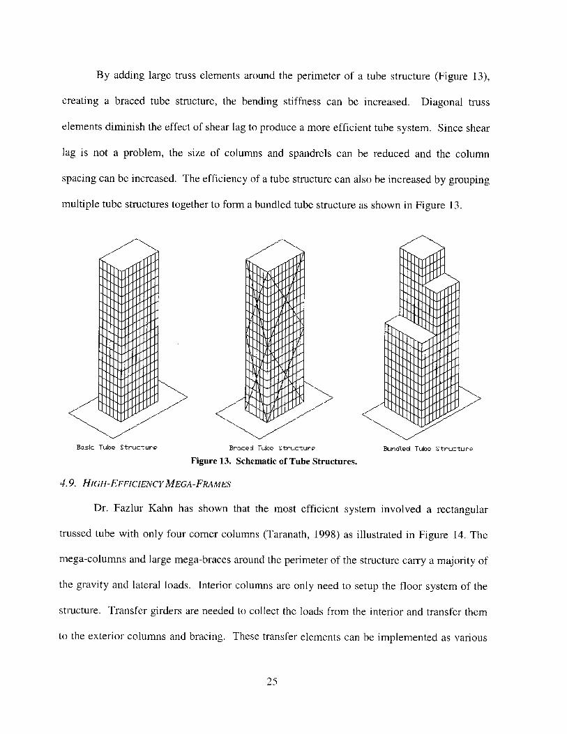
By adding large truss elements around the perimeter of a tube structure (Figure 13),
creating a braced tube structure, the bending stiffness can be increased. Diagonal truss
elements diminish the effect of shear lag to produce a more efficient tube system. Since shear
lag is not a problem, the size of columns and spandrels can be reduced and the column
spacing can be increased. The efficiency of a tube structure can also be increased by grouping
multiple tube structures together to form a bundled tube structure as shown in Figure 13.
Basic Tube Struc-ture Braced Tube Structure BundLed Tube StructurQ
Figure 13. Schematic of Tube Structures.
4.9. HIGH-EFFICIENCY MEGA -FRAMES
Dr. Fazlur Kahn has shown that the most efficient system involved a rectangular
trussed tube with only four corner columns (Taranath, 1998) as illustrated in Figure 14. The
mega-columns and large mega-braces around the perimeter of the structure carry a majority of
the gravity and lateral loads. Interior columns are only need to setup the floor system of the
structure. Transfer girders are needed to collect the loads from the interior and transfer them
to the exterior columns and bracing. These transfer elements can be implemented as various
25
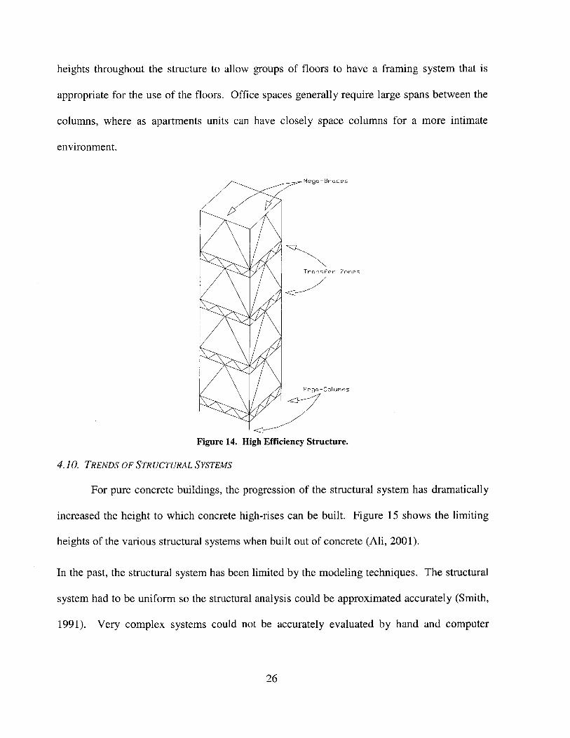
heights throughout the structure to allow groups of floors to have a framing system that is
appropriate for the use of the floors. Office spaces generally require large spans between the
columns, where as apartments units can have closely space columns for a more intimate
environment.
Mega-Braces
Transfer Zones
Mega-Columns
Figure 14. High Efficiency Structure.
4.10. TRENDS OF STRUCTURAL SYSTEMS
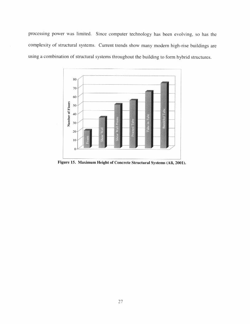
For pure concrete buildings, the progression of the structural system has dramatically
increased the height to which concrete high-rises can be built. Figure 15 shows the limiting
heights of the various structural systems when built out of concrete (Ali, 2001).
In the past, the structural system has been limited by the modeling techniques. The structural
system had to be uniform so the structural analysis could be approximated accurately (Smith,
1991). Very complex systems could not be accurately evaluated by hand and computer
26
processing power was limited. Since computer technology has been evolving, so has the
complexity of structural systems. Current trends show many modem high-rise buildings are
using a combination of structural systems throughout the building to form hybrid structures.
A
80
70-
60-
50-z
30-Z
20
I-W
Figure 15. Maximum Height of Concrete Structural Systems (Ali, 2001).
27
5. ADVANCEMENTS OF MATERIALS
In the early 20th century, the maximum height of buildings was severely limited.
Buildings did not extend to great heights until the development of structural steel. Steel has a
relatively high strength to weight ratio, is easily erected, has long spanning ability, and can be
used is many different types of structural schemes. In the mid- 1900's, reinforced concrete
was not very attractive structural material for use is very tall buildings because it is very labor
intensive and time consuming. Recent innovations in concrete material, forming, and
placement has made reinforced concrete a much more viable option for high-rise buildings.
Combining steel and concrete in high-rise buildings has also allowed the structures to sore to
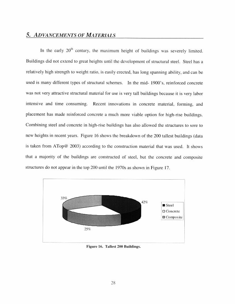
new heights in recent years. Figure 16 shows the breakdown of the 200 tallest buildings (data
is taken from ATop@ 2003) according to the construction material that was used. It shows
that a majority of the buildings are constructed of steel, but the concrete and composite
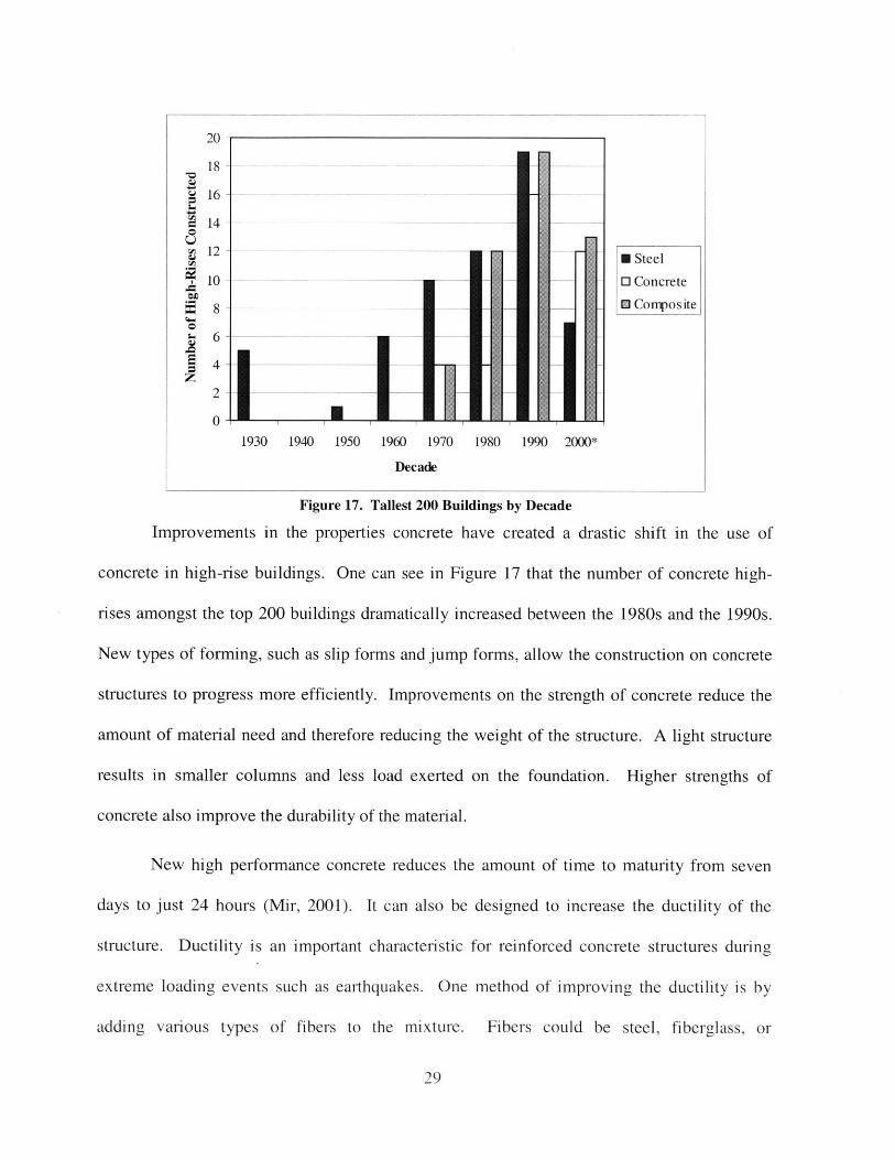
structures do not appear in the top 200 until the 1970s as shown in Figure 17.
Figure 16. Tallest 200 Buildings.
28
42%* Steel
O Concrete
* Composite
25%
I
20
18 --
16 -
4--
12 M Steel
10 -0 Concrete
8 -_ 0 Composite4-4
0
2
0-1930 1940 1950 1960 1970 1980 1990 2000*
Decade
Figure 17. Tallest 200 Buildings by Decade
Improvements in the properties concrete have created a drastic shift in the use of
concrete in high-rise buildings. One can see in Figure 17 that the number of concrete high-
rises amongst the top 200 buildings dramatically increased between the 1980s and the 1990s.
New types of forming, such as slip forms and jump forms, allow the construction on concrete
structures to progress more efficiently. Improvements on the strength of concrete reduce the
amount of material need and therefore reducing the weight of the structure. A light structure
results in smaller columns and less load exerted on the foundation. Higher strengths of
concrete also improve the durability of the material.
New high performance concrete reduces the amount of time to maturity from seven
days to just 24 hours (Mir, 2001). It can also be designed to increase the ductility of the
structure. Ductility is an important characteristic for reinforced concrete structures during
extreme loading events such as earthquakes. One method of improving the ductility is by
adding various types of fibers to the mixture. Fibers could be steel, fiberglass, or
29
polypropylene. Slurry infiltrated fiber concrete (SIFCON) is another method being developed
for improving the ductility of concrete. This consists of a layer of fibers that is infused with a
concrete slurry. The fibers occupy about 10% of the volume of the material which is much
higher than other concrete mixed with fibers. This material has deflection characteristics
similar to that of a steel slab (Walraven).
Within the past decade, high-rise structures have begun to fully integrate steel and
concrete throughout the building to maximize the efficiency of the structure. By combining
steel and concrete, one can use the material that is most effective for one particular region of
the structure. Steel has the ability to span large distances and can be easily and quickly
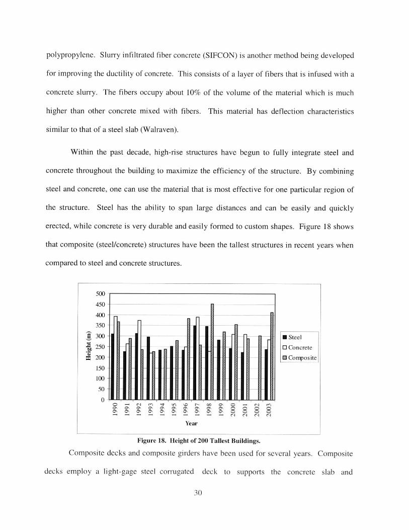
erected, while concrete is very durable and easily formed to custom shapes. Figure 18 shows
that composite (steel/concrete) structures have been the tallest structures in recent years when
compared to steel and concrete structures.
500
450 - --
400 .
350 -
300 - 0 Steel
250 - 0 Concrete
200- 0 Composite
150 -
100 -
50
0-C) "ON ON r- N O O N N O 0" C) MON ON ON ON oNl ON ON ON ON ON 0D 0 C0 0
C" C C* C" N 0 a, CN ON CD CD 0l
Year
Figure 18. Height of 200 Tallest Buildings.
Composite decks and composite girders have been used for several years. Composite
decks employ a light-gage steel corrugated deck to supports the concrete slab and
30
functions as tension steel on the bottom of the slab. Composite girders use steel shear studs
along the top of the girder to develop composite shear action at the interface between the steel
and concrete.
One of the most widely used composite elements is the composite column consisting
of a steel pipe or tube filled with high strength concrete. A composite column could also
involve a steel element that has been embedded in concrete. The first type is generally easier
to construct since the steel pipe serves as the formwork. In both cases, typically the steel
section is sized to support the construction loads. The concrete casting lags behind the steel
erection and the concrete only needs to reach maturity by the time significant loading is added
to the structure.
The steel section encased in concrete is generally only used for exterior columns since
the transfer of formwork from one story to the next is easier along the exterior of the
structure. This type of composite column also requires additional transverse reinforcement to
provide the necessary ductility for cyclic loading such as earthquakes.
The concrete-filled column is very efficient in construction since no formwork is
necessary and longitudinal and transverse steel can usually be eliminated. This type of
element could also be employed as a diagonal member. Several performance issues of these
composite columns have yet to be answered. Further study is needed on the bonding action
between the steel and concrete. In some instances, shear studs have been employed on the
inside of the steel pipe to insure that the composite action is achieved. Little is known about
local buckling of the steel along the length of the member or the performance of the member
when loaded beyond the point of yielding.
31
Research has been done on the concrete filled columns concerning the biaxial stress of
the steel section. When an axial load is imposed on the composite member, the steel is
strained circumferentially as wells as axially when the concrete tries to expand. This biaxial
state of stress decreases the maximum force that can be exerted on the member. To avoid this
problem, Aboutaha et. al. (1998) suggests the use of steel confined reinforced concrete
columns. These columns involve a typical reinforced concrete column with a steel pipe
section around it, but the steel section is terminated just short of beam joints. Therefore, the
steel pipe does not undergo direct axial compression and the strength characteristics of the
steel are improved. In this situation, the steel is function only as a confinement jacket for the
concrete and not as an axial loaded column.
Continual research and advancement of construction materials greatly benefits the
extents to which high-rise building can reach. Materials are becoming lighter and stronger
therefore making structures more efficient in resisting the loads acting on the structure
32
6. EFFICIENCY VS. REDUNDANCY
Innovations in high-efficiency structural systems, such as mega-braced frames, using
composite elements with high strength materials have resulted in fewer columns carrying a
majority of the load. As the efficiency of a structural system is maximized, the degree of
redundancy is reduced. The structure becomes very vulnerable to unpredictable events. Even
though the vulnerability of the structure is increased, the composite elements may be
sufficiently robust in order to resist unpredictable events individually (Abdelrazaq et. al,).
Redundancy can be defined in a number of different ways. Bertero et. al. (1999) was
able to distinguish between the redundancy associated with a pseudo-static earthquake
analysis and a dynamic earthquake analysis. The degree of redundancy for a pseudo-static
case is the number of plastic hinges "that must yield or fail to produce the impending collapse
of the structure under the action of monotonically increasing lateral deformations" (1999).
Therefore, a push-over analysis of the structure under the equivalent static lateral forces can
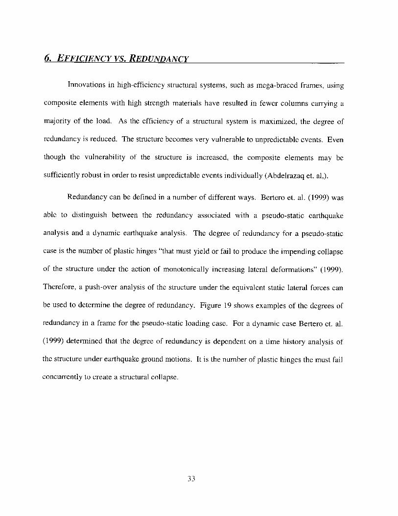
be used to determine the degree of redundancy. Figure 19 shows examples of the degrees of
redundancy in a frame for the pseudo-static loading case. For a dynamic case Bertero et. al.
(1999) determined that the degree of redundancy is dependent on a time history analysis of
the structure under earthquake ground motions. It is the number of plastic hinges the must fail
concurrently to create a structural collapse.
33
PtasticHinges
Static 4 Degrees of 12 Degrees ofIndeterminancy Reduncancy Reduncancy
Figure 19. Static Redundancy Under Earthquake Ground Motion.
Structural innovation has resulted in projects that extend beyond the limits of typical
design code. Therefore it becomes the responsibility of the engineer to assess the amount of
risk that is inherent in the structure and apply an appropriate design to insure that the
occupants of the building are safe. Extensive study has been done concerning the assessment
of structural vulnerability and risk. In the design of high-rise buildings it is essential to resist
progressive collapse by a small, or disproportionate, amount of damage. The University of
Bristol has developed a structural vulnerability theory that examines the connectivity of the
structural elements in order to identify failure modes. When combined with structural
response and reliability analysis, an assessment of risk and susceptibility of progressive
collapse can be determined (Blockley, 2002).
Melchers (2002) suggests the need for structural engineers to implement risk
assessments for buildings similar that which are done for hazardous facilities such as nuclear
power plants. This would allow the engineers to evaluate the potential of "low-probablitity-
high-consequence" events such as acts of war or terrorist attacks. As high-rise buildings grow
taller and taller, the consequence of such events is also increased.
34
7. PERFORMANCE-BASED DESIGN FOR FIRE
When designing a building, one is required to ensure that the structure can withstand
the forces that are acting on it in order to keep the occupants safe. Therefore, it is also
necessary to study the effects of the structure during a fire and design the structure to
withstand the blaze and not allow a catastrophic collapse.
Generally, fire resistive requirements of a structure are based on the types of materials
composing the structure. Building products are tabulated with various fire ratings, and
depending of the type of occupancy, the fire rating must be kept under a certain level. This
prescriptive type of design does not directly consider the structural integrity of the members
and is difficult to tailor to specific structural designs. Current trends in fire safety regulation
are moving toward performance-based regulation. According to Kokkala (1996), a
performance-based approach can allow for a 5% savings on total construction cost without
compromising any of the safety of the building. As technology is rapidly developing,
computer simulation of the behavior of fires is improving. Such analysis allows the engineer
the study the effects of a particular structure under an arbitrary fire situation. This is an
integral part of performance-based design for fire protection.
Solomon et. al (2002) determined that there are several elements of performance-
based design that will benefit the engineers and designers. A design can be highly specialized
to serve a specific function or hold some aesthetic quality. The engineer can reduce any
unnecessary redundancies of a prescriptive code that does not benefit the fire protection
system. A performance-based design also allows for more innovation of fire protection
methods to be developed.
35
There are several elements that need to be considered during the structural design of a
building when conducting a performance-based fire safety regulation. When building
materials are exposed to the extreme heat of a fire, the mechanical properties of the materials
are changed. These changes generally results in lower strengths and stiffnesses of the
structural elements. Additional internal forces are also exerted on the members due to the
extreme high temperatures. All of these issues decrease the total resistance of the element to
structural loads.
Since the occurrence of a fire has a relatively low probability, building codes have
implemented factors that reduce the amount of total load that each element is required to resist
while exposed to a fire. And, since a fire is considered to be an extreme event, it is not
necessary to design for deflection under extreme heat conditions.
Redundancy is essential to implement in a structure in order to withstand fire damage.
Fire damage is usually localized but could cause failure of major structural elements in the
small area. If the structure has redundancy incorporated, the forces that were carried by the
failed structural member can be redistributed to other elements that have significant reserve
strength. Any amount of redundancy is generally effective since the structure is generally not
under extreme loads in the event of a fire. To be effective during a fire, a redundant structure
needs to be very ductile in order to accommodate large deflections.
The effects of fire damage are largely dependent on the type of structural material and
the amount of fire protection that is provided to the structural elements. Steel elements can be
extremely vulnerable to fire since steel has a high thermal conductivity and the members are
usually thin. Therefore the heat propagates throughout the member quickly and causes a
36
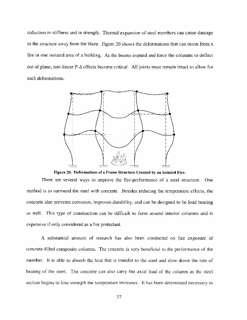
reduction in stiffness and in strength. Thermal expansion of steel members can cause damage
to the structure away from the blaze. Figure 20 shows the deformations that can occur from a
fire in one isolated area of a building. As the beams expand and force the columns to deflect
out of plane, non-linear P-A effects become critical. All joints must remain intact to allow for
such deformations.
Figure 20. Deformations of a Frame Structure Created by an Isolated Fire.
There are several ways to improve the fire-performance of a steel structure. One
method is to surround the steel with concrete. Besides reducing the temperature effects, the
concrete also prevents corrosion, improves durability, and can be designed to be load bearing
as well. This type of construction can be difficult to form around interior columns and is
expensive if only considered as a fire protectant.
A substantial amount of research has also been conducted on fire exposure of
concrete-filled composite columns. The concrete is very beneficial to the performance of the
member. It is able to absorb the heat that is transfer to the steel and slow down the rate of
heating of the steel. The concrete can also carry the axial load of the column as the steel
section begins to lose strength the temperature increases. It has been determined necessary to
37
have holes drill at every floor in order to allow the steam from the concrete to be released and
prevent bursting of the steel (Buchanan, 2001).
Another fire protection system involves encasement with gypsum or calcium silicate
board. These boards are easy to install and provide a good surface for interior finishing.
Replacements is usually required if the boards are exposed to a fire.
Spray-on fire resistant systems are usually the cheapest and easiest to apply to steel
members. The effectiveness of spray-on systems is strongly dependent on the adhesiveness of
the material to the steel elements. The spray-on material could either be a cement-base with
fiber reinforcement or intumescent paint that swells up when heated. Areas that are
vulnerable to damage must be protected to insure that the material is not removed. The
intumescent paint is more attractive for exposed members since the cement-based concoction
is very thick and messy. Intumescent paint cannot be casually inspected since one cannot
easily determine the thickness of the paint layers.
Concrete is generally less susceptible to fire damage than steel since it has a low
thermal conductivity. But, concrete becomes vulnerable when the temperature is high enough
to cause the cover to spall off. High strength concrete seems have more problems with
explosive spalling than normal weight concrete. Lightweight concrete has more fire
resistance than normal weight concrete. Since the lightweight aggregates are products of a
high temperature process, their properties are nearly constant at elevated temperatures
(Buchanan, 2001). Fiber reinforced concrete can behave well when exposed to fire depending
on the type of fibers that are used. Polypropylene fibers melt and form passages for the steam
to escape from the concrete and therefore spalling is reduced.
38
8. EMERGENCY EGRESS
Since the event of a fire is somewhat inevitable, and it would not be economically
feasible to design a building to be totally fireproof, extensive consideration has been given to
the exiting procedures in high-rise buildings. When dealing with very tall buildings, the
typical exit path down a stairwell may consist of 50 or more stories of decent. During an
emergency situation, the stairways become congested and the rate of decent is slowed. It has
been proposed to implement wider stairways and corridors on the lower floors of skyscrapers
to allow for the accumulation of traffic near the bottom floor to flow easier. But, this
obviously uses an exorbitant amount of space and is not economically attractive.
So how can appropriate paths of egress be provided? Several new methods are being
considered that have not be used in the past. In areas that are highly urbanized, one may
consider extending escape routes to other adjacent buildings. This would be a relatively
simple fix that could serve as escape routes for either building. This would also be a passive
system that would not require any mechanical maintenance. Having a sky bridge to an
adjacent building would also allow for occupants of the floors above the damaged level to
evacuate the building safely.
Recent study has also focused on using various types of egress paths along the exterior
of the building. Deployable chutes could be installed along the perimeter of the building
inside a removable spandrel panel just below the floor slabs. The chutes would be fabricated
from a fire proof, high tensile strength textile. In an emergency the chutes could be deployed
manually or automatically. Manual operation would be desirable in the event of power
failure. Since fires or other emergencies are usually limited to a couple of floors the escape
39
chutes may only need to extend four or five floors to allow occupants to avoid the damaged
area. They could also be deployed at multiple levels to allow for a continuous escape route to
ground level if necessary. One could also consider using deployable devices that extend
across to adjacent buildings. The occupants could then use the standard egress paths of the
other building.
A technique that would be simple to implement is the use of perimeter wall rescue
vehicles. This type of vehicle is what is normally used for window washing and other exterior
maintenance. The unit is simply lowered from a support structure at the top of the building to
collect trapt occupants and lower them along the fagade of the building to the ground level.
These systems are usually driven with a mechanical wench system that would be inoperable
in a power outage; therefore manual systems need to be considered.
Another more complicated method of egress from tall buildings could utilize
emergency rescue platforms. These vehicles would essentially be a hovering platform that is
controlled like a helicopter. A greater amount of risk is associated with the successful transfer
of building occupants to the flying platform than the other evacuation methods.
The new World Financial Center in Shanghai will incorporate refuge floors every
fifteen levels. These floors will be essentially fire proof and contain no furniture. There sole
purpose will be to act as a safe haven for the occupants of the building until further evacuation
procedures occur.
There are many alternatives for evacuation of very tall buildings currently under
consideration. All of the systems discussed provide another egress option for the occupants in
case the primary path, usually down a central core, is damaged. Providing this additional path
40
of egression is the same as implementing rdundancy the structural system. Having a more
redundant structure will lead to a safer and more reliable structure.
41
9. CASE STUDIES
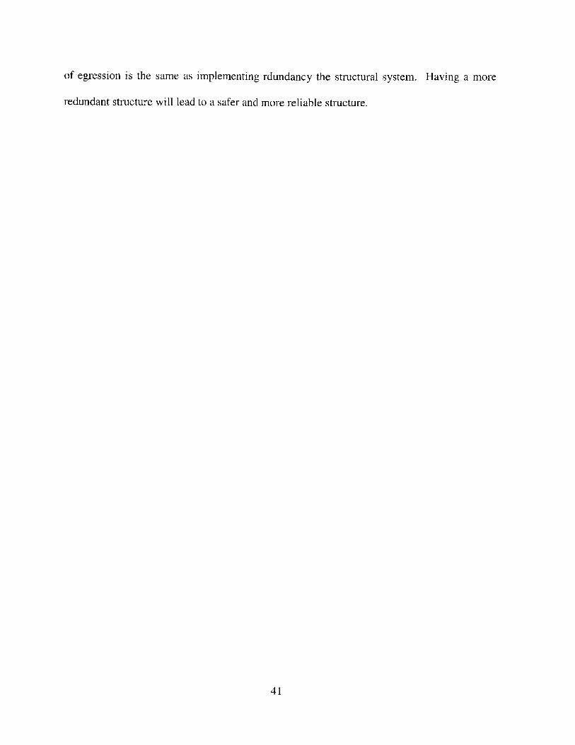
9.1. PETRONAS TOWERS, KUALA LUMPUR, MALASIA
The Petronas Towers (Figure 21), the world's tallest buildings, were completed in
1998 in Kuala Lumpur. The towers extend to 1,483 ft (452 m) with 88 floors above ground
and 5 floors below ground. The programming of the building is divided among office, retail,
and entertainment space. The structural engineering was complete by Thorton-Tomasetti
Engineers.
re 21. rnotograph or Petronas Towers (15ocaning, 2JWJ).
42
The lateral structural system involves a reinforced concrete core and mega-columns
that connected by ring-beams along the perimeter of the building. The concrete core has a
maximum dimension of 75 ft at the base of the towers and tapers to 62x72 ft. The columns
have diameters up to 7.8 ft (2.4 m). The concrete used in the structure have compressive
strengths from 5,800 up to 11,600 psi. The mass and stiffness of the concrete was appropriate
for the lateral system, but steel was used for the floor system to speed up the construction
process and take advantage of the spanability so interior columns would not be required. A 2-
story deep outrigger connects the core to the perimeter columns at level 38 to increase the
efficiency of the lateral system. The structural scheme holds the lateral drift angle to 1/560.
Since the two towers are in close proximity, it was necessary to conduct wind tunnel
test to evaluate the coupled effects of the wind between the two towers. With a design 3-sec
mean wind speed of 78 mph (35.1 m/sec) at a height of 33 ft (10 m), the maximum
acceleration was only 20 milli-g. This is below the acceptable level of acceleration of 25
milli-g. The fundamental period of the towers was determined to be 9 sec.
9.2. JIN MAO TOWER, SHANGHAI, CHINA
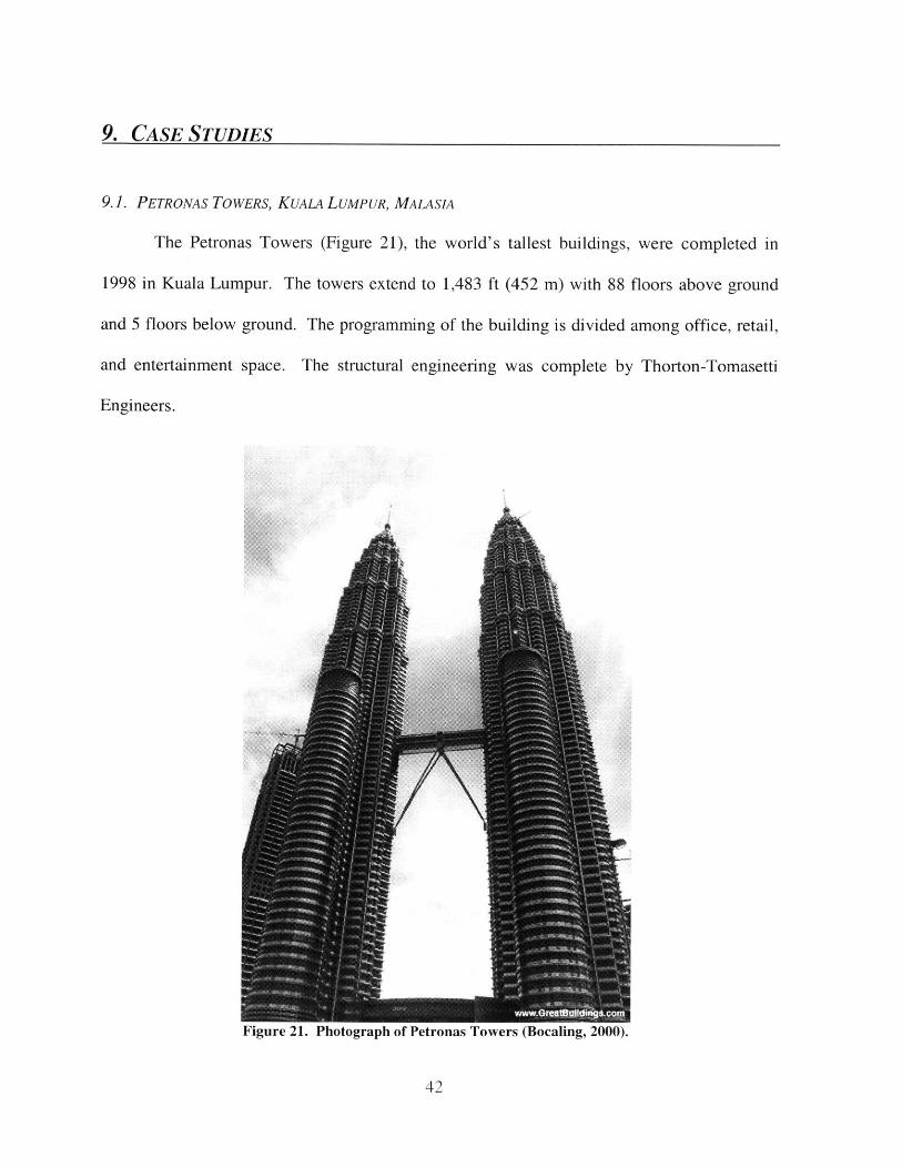
Completed in 1998, this 1381-ft (421-m) tall mix-use high-rise structure is the tallest
building in China and the forth tallest building on the planet behind only the Petronas Towers
of Kuala Lumpur and the Sears Tower of Chicago. The 88 floors of the Jin Mao Tower
(Figure 22) are composed of 50 stories of office space, 36 floors of a hotel, and two floors for
a restaurant and an observatory. The architecture of the building utilized traditional Chinese
forms and employees a tapered tiered scheme similar to that of Chinese pagodas. The
architecture and structural design was performed by Skidmore, Owings, and Merrill.
43
Figure 22. Photograph of the Jin Mao Tower (Shanghai, 2003).
The lateral rigidity of the tower was achieved by employing a steel/concrete composite
structure. The structural scheme involves a combined core structure and outrigger bracing
scheme. The exterior columns are composite mega-columns composed of a steel sections
encased in a rectangular concrete section. The dimensions of the mega-columns range from
3x11 ft to 5x16 ft. The concrete has compressive strengths ranging from 5000 to 7500 psi.
The mega-columns are connected to the reinforced concrete core by 2-story deep steel
outrigger trusses at three levels: 24-26, 51-53, and 85-87.
The earthquake loading that the structure was designed for was similar to the 1994
UBC, Zone 2A earthquake. The structural design was controlled by the dynamic wind
behavior of the structure. The wind loading consisted of 100-yr return wind speed, which is
equivalent to a 10-min sustained wind at 75 mph (33.5 m/s). Aeroelastic wind tunnel tests
44
were performed to asses the magnitude of accelerations that the building would experience
under the wind loading. An inherent structural damping of 1.5% was assumed for the testing.
The results showed the fundamental period of the building to be 5.7 sec, and the accelerations
for a 1-yr wind was only between 3 and 5 milli-g (g = 32.2 ft/sec2, 9.81 m/sec2 ). A 10-yr
wind only produced accelerations on the order of 10 milli-g. Load return periods were tested
since accelerations from wind loading are a serviceability requirement. The accelerations are
well below the acceptable level of acceleration at 25 milli-g; therefore the designers decided
that mechanical dampers were not necessary for this building.
The drift of the tower under a 50-yr return wind loading and 2.5% damping is only
1/1142. The drift angle is estimated to be 1/857 after two nearby proposed high-rises are
constructed. Even under an equivalent 3000-yr wind, the drift is only expected to be on the
order of 1/575. This tower is obviously very rigid with respect to lateral loading since typical
acceptable drift angles are on the order of 1/200.
The Jin Mao Tower is a good example of a modem high-rise structure that uses a
combination of structural systems and materials. The integration of steel and concrete is a
hybrid structural scheme maximizes the efficiency of the structure in resisting the gravity and
lateral loading.
45
10. CONCLUSION
High-rise buildings have progressed in a number of ways: advancement of the
structural system, improvement of the materials, and better egress strategies. Such progress
allows for buildings to be built taller and safer. Advancements of computer technology has
allowed for the development of hybrid structures that were previously difficult to model.
Fiber reinforced concrete ads a significant amount of ductility to concrete, and it can be very
resistant to fire when polypropylene fibers are used. Recent trends are attempting to move
away from the typical prescriptive design for fire resistances and focus on performance-based
design. And, for instances when the fire cannot be controlled, new egress strategies such as
deployable chutes will allow the occupants to evacuate quickly and safely. As long as all of
these areas continue to be developed, one can only guess at what heights that future high-rises
will reach.
46
Al. REFERENCES
Abdelrazaq, A. K., and Sinn, R. C. "Robustness and Redundancy Design for Tall Buildings."
Abouthaha, R. S., and Machado, R. (1998). "Seismic Resistance of Steel ConfinedReinforced Concrete (SCRC) Columns." Struct. Design of Tall Build. John Wiley &Sons. New York, NY.
Ali, M. M. (2001). "Evloution of Concrete Skyscrapers: from Ingalls to Jin Mao." Elctrnc.J. of Strct. Engng, EJSE, 1(1).
Baker, W. F. (2001). "Structural Innovation." Sixth World Congress on Tall Buildings andUrban Habitat. Melbourne, Australia.
Bocaling, A. (2000). "Petronas Towers." <http://www.greatbuildings.com> (May 11, 2003).
Bertero, R. D., and Bertero, V. V. (1999). "Redundancy in Earthquake-Resistant Design." J.of Struct. Engng., ASCE, 125(1), 81-88.
Blockley, D. I., Agarwal, J., Pinto, J. T., and Woodman, N. J., (2002). "StructuralVulnerability, Reliability, and Risk." Prog. Struct. Engng Mater. John Wiley & Sons.New York, NY.
Buchanan, A. H. (2001). Structural Design for Fire Safety. John Wiley & Sons. Chichester,UK
Kokkala, M. (1996). "Fire Safety of Buildings: Trends and the Roel of CIB W14."
Lee, K., Lee, L., and Lee, E. (2002). "Prediction of Shear-Lab Effects in Framed-TubeStructures with Internal Tube(s)." Struct. Design of Tall Build. John Wiley & Sons.New York, NY.
Melchers, R. E. (2002). "Safety and Risk in Structural Engineering." Prog. Struct. EngngMater. John Wiley & Sons. New York, NY.
"Top 200 Skyscrapers Worldwide." (2003). <http://www.skycrapers.com> (May 2, 2003).
Shanghai Municipal Government. (2003). "Jin Mao Tower (1)." <http://www.sh.gov.cn>(May 11, 2003).
Smith, B. S., and Coull, A. (1991). Tall Buildings Structures. John Wiley & Sons. NewYork, NY.
Solomon, R. E., and Hagglung, B. (2001). "Performance Code Requirements in the TallBuilding Environment." Sixth World Congress on Tall Buildings and Urban Habitat.Melbourne, Australia.
47
Taranath, B. S. (1998). Steel, Concrete, & Composite Design of Tall Buildings. SecondEdition. McGraw-Hill. New York, NY.
Walraven, J. "Challenges for New Materials in Concrete Structures." 1 3th FIP Congress.
48