trends of cadcam
TRANSCRIPT

8/8/2019 Trends of Cadcam
http://slidepdf.com/reader/full/trends-of-cadcam 1/155
CTTC-(An Indo-Danish Pro)
Ministry Of SSI
Bhubaneswar-24
TRENDS IN CAD/CAM
Swadesh.Bhusan. Mishra
Sr. Engineer .

8/8/2019 Trends of Cadcam
http://slidepdf.com/reader/full/trends-of-cadcam 2/155
10/06/10 [email protected]
•
An Indo – Danish Project Govt. of India Society under the
Administrative control of Ministry of SSI.
• We aims at Providing Consultancy to SSI, Conduction Long and
short course in Tool Engineering and cad/cam, Component
matching for Precision industries, Manufacture highly specialized
Tools, Jigs & Fixtures, Dies & moulds Etc for Industries for Home
and Abroad
• At CTTC We have High standard CNC M/Cs interfaced with finest
software in the world
• We operate at B-36 CNI Complex, Bhubaneswar-24 in lush green
area of 10 Acre with investment of 100 Cr.
CTTC, BHUBANESWAR

8/8/2019 Trends of Cadcam
http://slidepdf.com/reader/full/trends-of-cadcam 3/155
10/06/10 [email protected]
Vision of the cad/cam program
At CTTC
• Conducting the bridge course to give the firsthand industry experience to the fresh
technically trained young people from institution
and university
• Supplying adequate multi skill (cad/cam) man
power to the Indian industries and design center
to fill the shortage of man power in this sector.

8/8/2019 Trends of Cadcam
http://slidepdf.com/reader/full/trends-of-cadcam 4/155
10/06/10 [email protected]
Software in CTTC-Training
• AutoDesk Educational solution set.
• Solid Works
• CAMWorks
• Pro-E
• Uni-graphics• Catia
• Ideas
• Ansys
• Delcam
• MasterCAM
• Denford Tutors
• CNC Tutors
• GITA
• Tool Designer for AutocadUser

8/8/2019 Trends of Cadcam
http://slidepdf.com/reader/full/trends-of-cadcam 5/155
Focus
2. Why CAD/CAE/CAM.
4. What is FEA & ANSYS.
6. Analysis of some problems.
1. Implementation of CAD/CAE/CAM
5. Basic procedure of ANSYS.

8/8/2019 Trends of Cadcam
http://slidepdf.com/reader/full/trends-of-cadcam 6/155
A Quick Look CAD/CAM

8/8/2019 Trends of Cadcam
http://slidepdf.com/reader/full/trends-of-cadcam 7/155
An Engineer…
He is the Backbone of industries.
He is one who provide a complete solution to an any
engineering problem in his area of work toaccomplish comfortable product to the society by
using Men, Material Machine and Money.
Before Starting…..

8/8/2019 Trends of Cadcam
http://slidepdf.com/reader/full/trends-of-cadcam 8/155
Engineering TEAM With Out
Integration ?
What Costumer Wanted what You Have Supplied?

8/8/2019 Trends of Cadcam
http://slidepdf.com/reader/full/trends-of-cadcam 9/155
What is CAD?
CAD is concerned to support theDesign Engineering activity
CAD Includes
“ Creation of Geometric Modeling,Doing Engineering Analysis,Evaluating the Design andProduce Drafting for
Manufacturing” with help of computer
Geometric
Modeling
Engineering
Analysis
Design Review& Evaluation
Automated
Drafting
Synthesis
Analysis& Optimization
Evaluation
Presentation
Need
Analysis
Problem
definition
CAD

8/8/2019 Trends of Cadcam
http://slidepdf.com/reader/full/trends-of-cadcam 10/155
10/06/10 [email protected]
Geometric Modeling ?
• Modeling is creation of theDesired structure in CAD
system
• Modeling are categorized asWire Frame, Surface and
Solid Modeling.
Geometric
Modeling

8/8/2019 Trends of Cadcam
http://slidepdf.com/reader/full/trends-of-cadcam 11/155
10/06/10 [email protected]
What is Engineering Analysis ?
Engineering Analysis can be defined as “ Checking the
technical feasibility of the structures, when they aresubjected to certain Conditions and obtaining stress , strain etc.
It Reduces the No. of Product Development Cycle allowing
the business unit to thick for new design
Typical CAD Model Typical Analysis ResultAssembly of the Anchor plate
Mass properly analysis Tolerance and Tolerance checking
Interference checking Finite element Analysis
Optimization
Few Engineering Analysis
Engineering
Analysis

8/8/2019 Trends of Cadcam
http://slidepdf.com/reader/full/trends-of-cadcam 12/155
10/06/10 [email protected]
Design Review and Evaluation
Evaluation is defined as “Verifying the
functionality of the Assembly Design using
Kinematics Simulation”.
Kinematics and dynamic analysis
Error Checking
Types of Evaluation
Design Review
& Evaluation

8/8/2019 Trends of Cadcam
http://slidepdf.com/reader/full/trends-of-cadcam 13/155
10/06/10 [email protected]
Automated Drafting
Automated Drafting is the representation of the object in 2D of the
3D model which contains GT&D, Material specifications, Sectionalviews, Bill of Materials etc. Drafting is for Process planning (CCPP), Machining, Heat Treatment if any
It is also called Rapid Drafting
It is Normally developed from 3D Geometric Model
Automated
Drafting
D i P I CAD

8/8/2019 Trends of Cadcam
http://slidepdf.com/reader/full/trends-of-cadcam 14/155
10/06/10 [email protected]
Elicit
Feedback
Design Process In CADAn Industries approach
Use Prototype
To communicate idea Concept
And win new Business
Perform
Iterative
Design
Accelerate Design
Iterations and improveProduct Quality
Using Quick 3d Model
ConductFunctional
Testing
Share Design Conce
And get valuableFeedback From
members of the Produc
Development Team
Evaluate form, Fit & Function
Of Your Design and Eliminate theneed for Last-Minute Design Change
Tailor the Design to meetRestraints Of the Production
method and Reduce the material cost
Generate
New
Business
PlanFor
Manufacturing

8/8/2019 Trends of Cadcam
http://slidepdf.com/reader/full/trends-of-cadcam 15/155
10/06/10 [email protected]
TRENDS IN CAD/CAM
A Glance at CAM

8/8/2019 Trends of Cadcam
http://slidepdf.com/reader/full/trends-of-cadcam 16/155
10/06/10 [email protected]
What is CAM?
•CAM is Defined as “the effective use of computer technology in manufacturing
planning and control”.
CAM
Production Activity
Cost Estimation
Capacity planning
CPP
NC
Control Activity
Process PlanningProcess Monitoring
Computer aided Inspection

8/8/2019 Trends of Cadcam
http://slidepdf.com/reader/full/trends-of-cadcam 17/155
10/06/10 [email protected]
CAD Model
Planning
Program
Generation
TestSimulation
Sample NC Program
CAM is concerned with using computer to support the
manufacturing functions.
COMPUTER AIDED MANUFACTURING

8/8/2019 Trends of Cadcam
http://slidepdf.com/reader/full/trends-of-cadcam 18/155
10/06/10 [email protected]
What is CIM?
• It is an integrated approach to
maintain a Common
Database for CAD, CAM andBusiness control.

8/8/2019 Trends of Cadcam
http://slidepdf.com/reader/full/trends-of-cadcam 19/155
10/06/10 [email protected]
Elements of CIM
Text Book Representation
Factory
Operation
CAD/CAE
PDM/ePub.
RP,RE EtcBusiness
Controls/Recourse
Planning
CAM,CNC,FMS,
Robotics, IA Plan
Design
Business
Function
Mfg Control &
Planning
R& D
A Glance at

8/8/2019 Trends of Cadcam
http://slidepdf.com/reader/full/trends-of-cadcam 20/155
10/06/10 [email protected]
CAD is to support the design engineering activities. CAM is using computer to support the manufacturing
functions.
CAD/CAM is efforts to integrate the design and the
manufacturing activities of a firm into continuumactivities
CIM includes all of the CAD/CAM and also embrace
the business functions of a manufacturing.
CIM implements computer technology in all the
operational and information processing activities
related to manufacturing.
A Glance at CIM

8/8/2019 Trends of Cadcam
http://slidepdf.com/reader/full/trends-of-cadcam 21/155
10/06/10 [email protected]
HOWTO MEET CUSTOMER’S DEMAND?
CHALLENGES TO BE FACED IN MARKET!

8/8/2019 Trends of Cadcam
http://slidepdf.com/reader/full/trends-of-cadcam 22/155
10/06/10 [email protected]
CUSTOMERS REQUIREMENTS
V/S
SUPPLIED QUALITY
CUSTOMERS REQUIREMENTS

8/8/2019 Trends of Cadcam
http://slidepdf.com/reader/full/trends-of-cadcam 23/155
10/06/10 [email protected]
CUSTOMERS REQUIREMENTS
V/S
SUPPLIED TOOL QUALITY

8/8/2019 Trends of Cadcam
http://slidepdf.com/reader/full/trends-of-cadcam 24/155
10/06/10 [email protected]
INCREASING GLOBALIZATION
MORE FOCUS ON QUALITY & SERVICE
SHORTER DELIVERY PERIODS
T d t d “S d &

8/8/2019 Trends of Cadcam
http://slidepdf.com/reader/full/trends-of-cadcam 25/155
10/06/10 [email protected]
Today trends “Speed &
quality”
To meet the CUSTOMER demand
Speed is everything
QualityTime

8/8/2019 Trends of Cadcam
http://slidepdf.com/reader/full/trends-of-cadcam 26/155
10/06/10 [email protected]
COMMUNICATION !
CUSTOMER SUPPLIER
T id C t I t t d

8/8/2019 Trends of Cadcam
http://slidepdf.com/reader/full/trends-of-cadcam 27/155
10/06/10 [email protected]
To avoid error use Computer Integrated
approach in all the sphere of the company
activity
Supplier- Customer Relationshipbetween each Departments

8/8/2019 Trends of Cadcam
http://slidepdf.com/reader/full/trends-of-cadcam 28/155
10/06/10 [email protected]
IMPROPER
COMMUNICATION !
EFFECTS ?
CUSTOMER

8/8/2019 Trends of Cadcam
http://slidepdf.com/reader/full/trends-of-cadcam 29/155
10/06/10 [email protected]
CUSTOMER MARKETING ENGINEER
Project Confirmation

8/8/2019 Trends of Cadcam
http://slidepdf.com/reader/full/trends-of-cadcam 30/155
10/06/10 [email protected]
M
Engineering TEAM With Out Integration ?What Costumer Wanted what You Have Supplied?

8/8/2019 Trends of Cadcam
http://slidepdf.com/reader/full/trends-of-cadcam 31/155
10/06/10 [email protected]
THE TRACK OF ERROR
IN MANUFACTURING

8/8/2019 Trends of Cadcam
http://slidepdf.com/reader/full/trends-of-cadcam 32/155
10/06/10 [email protected]
Error
testPlastic cover
Marketing Dep.
Error possibility:
1 out of 20 = 5 %
CAM/CNC Dep.
Error possibility:1 out of 5 = 20 %
2D drawings
testGlider
Design Dep.
?3D
Workshop
•Projection views not correct
•Missing dimensions & Tolerances
•Inaccurate BOM
•Customer’s information lost•crucial information is not
forward to design dep
( surface finish, tol. design
change, Other requirements
etc.)
•Misinterpretation of drawing
(2D > 3D)
•Projection views not correct
•Missing dimensions &
Tolerances•Inaccurate BOM
•Misinterpretation of
drawing
•Programming error•Inaccurate BOM
“The traditional 2D workflow”
•Misinterpretation of drawing
•Incorrect cutting tools & fixture
•Wrong feed & speed•Wrong CNC program version
Customer
Mr..CHECK
Error possibility:
1 out of 5 = 20 %
Error possibility:
1 out of 10 = 10 %
Error possibility:
1 out of 10 = 10 %

8/8/2019 Trends of Cadcam
http://slidepdf.com/reader/full/trends-of-cadcam 33/155
10/06/10 [email protected]
HOW TO OVERCOME
TRACK OF ERROR

8/8/2019 Trends of Cadcam
http://slidepdf.com/reader/full/trends-of-cadcam 34/155
10/06/10 [email protected]
CAD/CAM CIM Actual
Implementatio
n…

8/8/2019 Trends of Cadcam
http://slidepdf.com/reader/full/trends-of-cadcam 35/155
10/06/10 [email protected]
Beyond Text Book Approach..
Actual Design process and concurrentEngineering in real time industries…

8/8/2019 Trends of Cadcam
http://slidepdf.com/reader/full/trends-of-cadcam 36/155
10/06/10 [email protected]
DESIGN PROCEDURES
CONCEPTUAL DESIGN AT QUOTATION STAGE
PHASE 1:
ACTUAL DESIGN FOR MANUFACTURING
PHASE 2:
DESIGN PROCEDURE PHASE 1

8/8/2019 Trends of Cadcam
http://slidepdf.com/reader/full/trends-of-cadcam 37/155
10/06/10 [email protected]
Tool requirementPaper drawing2D file or 3d file
ComponentDesign Output:
3D solid
Concept & sketch
Working out
Quotation(Mkt..)
Customer input:
????
Customer approves:
Component & Tool/Product Sketch
Quotation signed
Yes, this is the
start of the
actual design of
Tool/Product
DESIGN PROCEDURE PHASE -1(CONCEPTUAL)
DESIGN PROCEDURE PHASE -2

8/8/2019 Trends of Cadcam
http://slidepdf.com/reader/full/trends-of-cadcam 38/155
10/06/10 [email protected]
Design
Fine Tuning
Conceptual Design
Design Review
Release of Drawings
& 3D files
3D Solid componentTool Sketch
Tool specification
Brain Storming :All Designers &
Project group
Project group:The Designer,Marketing
& Production
Approved
yes
No
Design
”frozen” !!!!
DESIGN PROCEDURE PHASE 2(Actual design)

8/8/2019 Trends of Cadcam
http://slidepdf.com/reader/full/trends-of-cadcam 39/155
10/06/10 [email protected]
DESIGN & MANUFACTURING IN
COMPETATIVE WAY
IT IS NOT A MAGIC
DFM - DESIGN FOR MANUFACTURING
A CONCURRENT ENGINEERING CONCEPT

8/8/2019 Trends of Cadcam
http://slidepdf.com/reader/full/trends-of-cadcam 40/155
10/06/10 [email protected]
MANUFACTURING
CONCURRENT
ENGINEERINGCONCEPT
The Correct way of Product/Tool

8/8/2019 Trends of Cadcam
http://slidepdf.com/reader/full/trends-of-cadcam 41/155
10/06/10 [email protected]
Assembly
CMM
Inspection
EDM
CNC milling /
Standard
cutting tools
Confirm order
3D CAD
Pre tooling
3D CAM
Standard
mold base
Raw Material
Yes
My Product/Tool is on time
Marketing
2D/3D
The Correct way of Product/ToolManufacturing
Design
Planning &
Production
Purchasing
MIS
Concept
Concurrent activities / Time
Despatch
Heat
Treatment

8/8/2019 Trends of Cadcam
http://slidepdf.com/reader/full/trends-of-cadcam 42/155
TRENDS IN CAD/CAM
TRENDS in Geometric ModelingCTTC Student Project

8/8/2019 Trends of Cadcam
http://slidepdf.com/reader/full/trends-of-cadcam 43/155
10/06/10 [email protected]
A Quick Look Traditional CAD
Modeling
• B-Rep
• Boolean Functions
• CGS Tree
Surface of revolutionTabulated Cylinder
Ruled Surface
CAD Traditional

8/8/2019 Trends of Cadcam
http://slidepdf.com/reader/full/trends-of-cadcam 44/155
10/06/10 [email protected]
Boolean , Primitive and composite model
CAD Traditional

8/8/2019 Trends of Cadcam
http://slidepdf.com/reader/full/trends-of-cadcam 45/155
10/06/10 [email protected]
CASE2 - CTTC-Students MINI Projects
Photo Render View
Shaded View
Modeled by using B-rep and Boolean Function
Technique- A Traditional Method
Even General purpose Traditional CAD gives Brilliant presentation

8/8/2019 Trends of Cadcam
http://slidepdf.com/reader/full/trends-of-cadcam 46/155
10/06/10 [email protected]
Auto Render Image
Traditional CAD S stem

8/8/2019 Trends of Cadcam
http://slidepdf.com/reader/full/trends-of-cadcam 47/155
10/06/10 [email protected]
Traditional CAD System
• Offers 2D Interactive Drafting
• 3D Geometric Modeling
• Limited Modification Capability• Only Mass Property Analysis No FEA,DMU
• Does not offer Associative Assembly
• This System substitute Drafting Board Fully

8/8/2019 Trends of Cadcam
http://slidepdf.com/reader/full/trends-of-cadcam 48/155
Modern High End 3D System offer all Mechanical

8/8/2019 Trends of Cadcam
http://slidepdf.com/reader/full/trends-of-cadcam 49/155
10/06/10 [email protected]
Solution under one platform
Mechanical Design
Shape Design Analysis & Simulation
NC Manufacturing
Digital Mock-up
Equipments and System Desig
Ergonomic Design &
Analysis
Communication across Distance
Communicate Internally

8/8/2019 Trends of Cadcam
http://slidepdf.com/reader/full/trends-of-cadcam 50/155
Today’s Trend In CAD Modeling ?
• Feature Based –Parametric Modeling
• Class A Surfacing
• IN Context Modeling and Assembly
• Rapid Drafting• Bi-directional Association
• Versatile formats
• Brilliant Presentation
• All solution at one umbrella
• Updated Export import facility
Further IT offers……..

8/8/2019 Trends of Cadcam
http://slidepdf.com/reader/full/trends-of-cadcam 51/155
10/06/10 [email protected]
• Helps Product Design under practical constrains• Helps enormously Imaginative concept
• Provides Optimality of design that are Value engineere
for cost
• Drawing produced form 3D confirms to updated ANSI
ISO Std
• Design Confirms to ASME,IS,DIN, ASE etc
• Mechanical Libraries
Today’s Trend In CAD Modeling ?
And Many More
Design Concepts

8/8/2019 Trends of Cadcam
http://slidepdf.com/reader/full/trends-of-cadcam 52/155
10/06/10 [email protected]
Design Intent
Feature-Based Modeling
Parametric Design
Associativity
Design Concepts
While designing project in Feature based Parametric
software, you need to understand a few basic design
concepts

8/8/2019 Trends of Cadcam
http://slidepdf.com/reader/full/trends-of-cadcam 53/155
10/06/10 [email protected]
Design Intent
• Before design the model, identify the design intent . • Design intent defines the purpose and function of
the finished product based on product
specifications or requirements.• Capturing design intent builds value and longevity
into your products.• This key concept is the core of the any feature-
based modeling process
F t B d M d li

8/8/2019 Trends of Cadcam
http://slidepdf.com/reader/full/trends-of-cadcam 54/155
10/06/10 [email protected]
Feature-Based Modeling• Part modeling begins with
creating individual geometricfeatures one after another.
• These features become
interrelated to other features
as you reference themduring the design process.
• A Lump of the part is called
Feature.
Sketch Based Feature
Dress Up Feature
Work Feature
P t i D i

8/8/2019 Trends of Cadcam
http://slidepdf.com/reader/full/trends-of-cadcam 55/155
10/06/10 [email protected]
Parametric Design• The interrelationships between
features allow the model tobecome parametric .
• If alteration made in one
feature will automatically
change other related(dependent) features.
• This parametric ability
maintains the integrity of the
part and preserves the design
intent.
• Dimensional and Geometrical
Constrains Plays a major in
this parametric design Tech.

8/8/2019 Trends of Cadcam
http://slidepdf.com/reader/full/trends-of-cadcam 56/155
10/06/10 [email protected]
Associativity
• CAD System maintains design intent outside of
Part mode through associativity .
• As continue to design the model, we can add
parts, assemblies, drawings, and other
associated objects, such as piping, sheet metal,or electrical wiring.
• All these functions are fully associative . So, any
changes in the design at any level, the project
will dynamically reflect the changes at all levels,preserving design intent.
Assembly Design Methods

8/8/2019 Trends of Cadcam
http://slidepdf.com/reader/full/trends-of-cadcam 57/155
10/06/10 [email protected]
Assembly Design Methods
Bottom-up Design
Top-Down Design
B tt D i

8/8/2019 Trends of Cadcam
http://slidepdf.com/reader/full/trends-of-cadcam 58/155
10/06/10 [email protected]
Bottom-up Design
• Bottom-up design is the traditional method.
• In bottom-up design, parts are create parts,
insert them into an assembly, and mate them
as required by your design.
• Bottom-up design is the preferred technique
when you are using previously constructed,
off-the-shelf parts.
B D i

8/8/2019 Trends of Cadcam
http://slidepdf.com/reader/full/trends-of-cadcam 59/155
10/06/10 [email protected]
Bottom-up DesignAdvantage
• Components are designed independently,
their relationships and regeneration
behavior are simpler.
• Working bottom-up allows you to focus on
the individual parts.• It is a good method to use if you do not
need to create references that control the
size or shape of parts with respect to
each other.
• Good for general purpose Mechanical
Design
T d D i

8/8/2019 Trends of Cadcam
http://slidepdf.com/reader/full/trends-of-cadcam 60/155
10/06/10 [email protected]
Top-down Design
• Starting part design in the assembly work Bench.
• Geometry of one part to help define other parts
• Create machined features that are added only after
the parts are assembled.• Can be start with a layout sketch, define fixed part
locations, planes, and so on, then design the parts
referencing these definitions.
T d D i
8/8/2019 Trends of Cadcam
http://slidepdf.com/reader/full/trends-of-cadcam 61/155
10/06/10 [email protected]
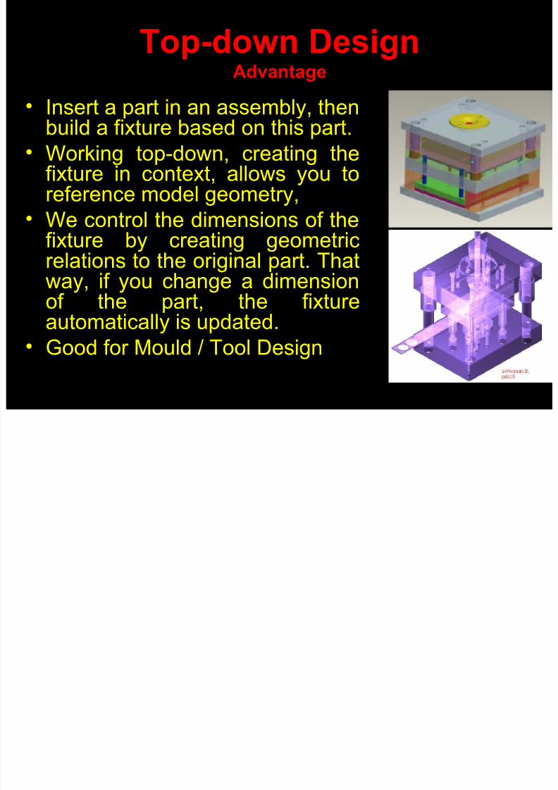
Top-down DesignAdvantage
• Insert a part in an assembly, thenbuild a fixture based on this part.
• Working top-down, creating thefixture in context, allows you to
reference model geometry,• We control the dimensions of the
fixture by creating geometricrelations to the original part. Thatway, if you change a dimensionof the part, the fixtureautomatically is updated.
• Good for Mould / Tool Design
Modeling Process in Feature Based Parametric CAD

8/8/2019 Trends of Cadcam
http://slidepdf.com/reader/full/trends-of-cadcam 62/155
10/06/10 [email protected]
Feature Based
Parametric
Modeling
Creating
Assemblies
Capturing Design Intent
Incorporate Engg. Knowledge
Into Solid Model using
Relationship, Pattern etc
Create new part based
On assembly,
Dim. & Clearance
Build parts by combining
features relative to each other
And in a logical order.
pattern features with in a part;
Create family tables of related
parts.
• Assemble parts related to each
other And in a logical order • pattern features with in an
assembly, Create family tables of
related Assemblies
Drawing
Analysis
Machining
Applicatio
CASE 1 RESEARCH
8/8/2019 Trends of Cadcam
http://slidepdf.com/reader/full/trends-of-cadcam 63/155
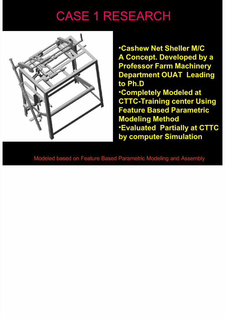
CASE 1 RESEARCH.
•Cashew Net Sheller M/C
A Concept. Developed by a
Professor Farm Machinery
Department OUAT Leading
to Ph.D•Completely Modeled at
CTTC-Training center Using
Feature Based Parametric
Modeling Method•Evaluated Partially at CTTC
by computer Simulation
Modeled based on Feature Based Parametric Modeling and Assembly
CASE 1 VIEWS

8/8/2019 Trends of Cadcam
http://slidepdf.com/reader/full/trends-of-cadcam 64/155
CASE 1 VIEWS (Cashew Net Sheller M/C
Patent Awaited
CASE2 CTTC Students Modeling

8/8/2019 Trends of Cadcam
http://slidepdf.com/reader/full/trends-of-cadcam 65/155
CASE2- CTTC- Students Modeling
Works
Modeling Used by Latest Feature Based Parametric Techniques-
A Latest Method of Design Approach.
CASE4 SOME OF THE FUEL

8/8/2019 Trends of Cadcam
http://slidepdf.com/reader/full/trends-of-cadcam 66/155
CASE4 SOME OF THE FUEL
SYSTEM LRU’S
Modeling Used by Latest Feature Based Parametric Techniques-
A Latest Method of Design Approach.
8/8/2019 Trends of Cadcam
http://slidepdf.com/reader/full/trends-of-cadcam 67/155
10/06/10 [email protected]
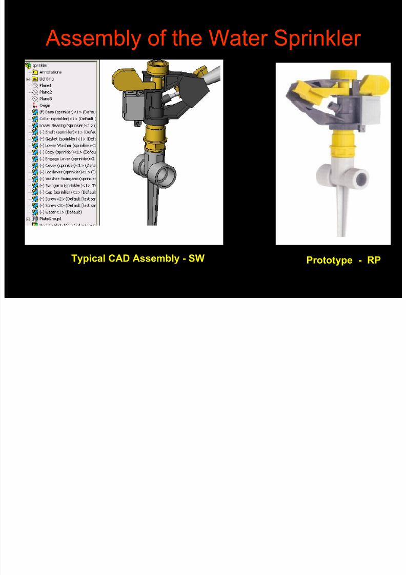
Assembly of the Water Sprinkler
Prototype - RPTypical CAD Assembly - SW

8/8/2019 Trends of Cadcam
http://slidepdf.com/reader/full/trends-of-cadcam 68/155
10/06/10 [email protected]
Blow off cock – A Boiler Mounting
Cl “A” S f i
8/8/2019 Trends of Cadcam
http://slidepdf.com/reader/full/trends-of-cadcam 69/155
10/06/10 [email protected]
Class “A” Surfacing
•
‘A’ class surfaces are those aesthetic/ free formsurfaces, which are visible to us (interior/exterior),
having an optimal aesthetic shape and high surface
quality.
• Mathematically class A surface are those surfaceswhich are curvature continuous while providing the
simplest mathematical representation needed for the
desired shape/form and does not have any undesirable
waviness.• To achieve a good class surface it requires good
surfacing skills and understanding of the form or flow of
the reference object.
Surfacing

8/8/2019 Trends of Cadcam
http://slidepdf.com/reader/full/trends-of-cadcam 70/155
10/06/10 [email protected]
SurfacingThe highlight plot (color plot /zebra plot), curvature plot (needle/value) of
the surface is a very help in finalising the Surface quality
Highlight is the behaviour of the form or Shape of a surface when a light
or nature reflects on it. This reflection of light or nature gives
you an understanding about the quality of surf ace. This reflection required
should be natural, streamline and with uniformity.

8/8/2019 Trends of Cadcam
http://slidepdf.com/reader/full/trends-of-cadcam 71/155
10/06/10 [email protected]
Surfacing
Two Wheeler Head Light Body

8/8/2019 Trends of Cadcam
http://slidepdf.com/reader/full/trends-of-cadcam 72/155
10/06/10 [email protected]
Customer Application Examples
Trends in CAD
Geometric Modeling
SURFACE MODELING
SURFACE MODELING EXAMPLES
EXAMPLES

8/8/2019 Trends of Cadcam
http://slidepdf.com/reader/full/trends-of-cadcam 73/155
10/06/10 [email protected]
3D MODELING
3D MODELING EXAMPLES
EXAMPLES

8/8/2019 Trends of Cadcam
http://slidepdf.com/reader/full/trends-of-cadcam 74/155
10/06/10 [email protected]
SURFACE MODELLING FOR
DIE OF EICHER
SOLID MODELLING FOR
DUMPER CAB FIXTURE OF
TELCON
3D SURFACE MODELLING
3D SURFACE MODELLING

8/8/2019 Trends of Cadcam
http://slidepdf.com/reader/full/trends-of-cadcam 75/155
10/06/10 [email protected]
CARLINE ORIENTATIONFIXTURES
FOR
ASHOK LEYLAND
3D SURFACE MODELLING
3D SURFACE MODELLING EXAMPLES
EXAMPLES

8/8/2019 Trends of Cadcam
http://slidepdf.com/reader/full/trends-of-cadcam 76/155
10/06/10 [email protected]
PANEL CHECKING FIXTURESFOR
MAHINDRA TRACTORS LTD.

8/8/2019 Trends of Cadcam
http://slidepdf.com/reader/full/trends-of-cadcam 77/155
10/06/10 [email protected]
Trends In CAM
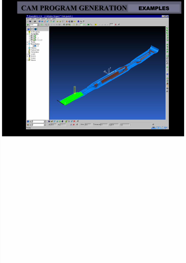
CAM PROGRAM GENERATION
Customer Application
Examples
CAM PROGRAM GENERATION
CAM PROGRAM GENERATION EXAMPLES
EXAMPLES

8/8/2019 Trends of Cadcam
http://slidepdf.com/reader/full/trends-of-cadcam 78/155
10/06/10 [email protected]
FRONT DOME
FOR
PIAGGIO
FIXTURE
FOR
TOYOTA
CAM PROGRAM GENERATION
CAM PROGRAM GENERATION EXAMPLES
EXAMPLES

8/8/2019 Trends of Cadcam
http://slidepdf.com/reader/full/trends-of-cadcam 79/155
10/06/10 [email protected]
VIRTUAL SIMULATION OF
CNC MILLING
FOR
BAL EV DOOR
CAM PROGRAM GENERATION
CAM PROGRAM GENERATION EXAMPLES
EXAMPLES

8/8/2019 Trends of Cadcam
http://slidepdf.com/reader/full/trends-of-cadcam 80/155
10/06/10 [email protected]
UPPER DRAW
DIE FOR
DOOR INNER
LOWER DRAW
DIE FOR
DOOR INNER
DRAW DIE OF DOOR INNER FOR
TOYOTA QUALIS
CAM PROGRAM GENERATION
CAM PROGRAM GENERATION EXAMPLES
EXAMPLES
8/8/2019 Trends of Cadcam
http://slidepdf.com/reader/full/trends-of-cadcam 81/155
10/06/10 [email protected]
BENDER PUNCH
FOR
BHARAT FORGE

8/8/2019 Trends of Cadcam
http://slidepdf.com/reader/full/trends-of-cadcam 82/155
10/06/10 [email protected]
CNC MILLINGCNC MILLING
A Typical CNC MACHINES Shop
A Typical CNC MACHINES Shop

8/8/2019 Trends of Cadcam
http://slidepdf.com/reader/full/trends-of-cadcam 83/155
10/06/10 [email protected]
MI
LLIN
GM
ACHIN
ES
RAMBAUDI VERSAMATIC 3 AXIS MILLING MACHINE
RAMBAUDI HIGH SPEED 3 AXIS MILLING MACHINES
1) MODEL : B 20 L
2) MODEL : B 27 L
BATLIBOI 3 AXIS MILLING M/C
CNC Milling

8/8/2019 Trends of Cadcam
http://slidepdf.com/reader/full/trends-of-cadcam 84/155
10/06/10 [email protected]
CNC Milling
CNC MICRON WF-32 C/32 DE
(Travel in XYZ 600x600x450/560x500x400
Table Size: 520x800/460x800)
A Typical CNC MACHINES Shop
A Typical CNC MACHINES Shop

8/8/2019 Trends of Cadcam
http://slidepdf.com/reader/full/trends-of-cadcam 85/155
10/06/10 [email protected]
X Y Z
2.000 1.500 0.900
B A C
4.700 3.700 4.500
MODEL WEIGHT
B 20 L 23.000
RAMBAUDI HIGH SPEED 3 AXIS MILLING M/C (B20L)
CNC L th

8/8/2019 Trends of Cadcam
http://slidepdf.com/reader/full/trends-of-cadcam 86/155
10/06/10 [email protected]
CNC Lathe
• CNC LATHE :
MAZAK QT-15
Max. Cutting Diameter : 254mm
Max. Work length : 350mmDistance between center : 500mm
• ACE DESIGNER LT-16 CNC
Max. Cutting Diameter : 250mm
Max. Work length : 350mm
Distance between center : 450mm
C C

8/8/2019 Trends of Cadcam
http://slidepdf.com/reader/full/trends-of-cadcam 87/155
10/06/10 [email protected]
CNC EDM
• CNC WIRE EDM –AGIECUT 220C
Max. work piece dimension:LxWxH : 860x580x250mm
Max. travel in XYZ :400x250x250mm
• CNC WIRE EDMELECTRONICA :MAXICUT 334
Max. work piece dimension:LxWxH : 500x400x150mm
Max. travel in XYZ : 400x300x150mm
CNC EDM

8/8/2019 Trends of Cadcam
http://slidepdf.com/reader/full/trends-of-cadcam 88/155
10/06/10 [email protected]
CNC EDM
• CNC DIE SINKING : AGIETRON 250C
Max. work dimension:LxWxH1000x700x320mm
Max. travel in XxYxZ :
700x500x500mm
• CNC DIE SINKING: AGIETRON 150C
Max. work dimension: LxWxH 780x500x220mm
Max travel in XxYxZ : 350x250x350mm• DIE SINKING ELECTRONICA: EMS 5535/R-50
Max. work dimension: LxWxH :300x200x250mm
Max. travel in XxYxZ: 300x200x250mm
CNC EDM CD Jacket Mould

8/8/2019 Trends of Cadcam
http://slidepdf.com/reader/full/trends-of-cadcam 89/155
10/06/10 [email protected]
CNC EDM - CD Jacket Mould
Machining description
• Part material : Steel 1.2083• Electrode material : Cooper •
No. Elec for 4 cavity : 3 (1 roughing, 2 finishing• Electrode undersize : 0.25mmRG, 0.15mmFI• Final surface finish : Ra. 3.2/CH30• Main Accuracy : +/- 5micron• Machining surface : 170cm2
• Maximum cavity depth : 2mm• EDM hours for all the mould : 12 hours• Programming type (pc, machine) : on the machine
Mould for CD jacket requiring
perfect flatness and perfect
surface finish consistency
Customer Application Examples
CNC EDM Mobil phone mould

8/8/2019 Trends of Cadcam
http://slidepdf.com/reader/full/trends-of-cadcam 90/155
10/06/10 [email protected]
Only electrodes are made with HSM
Today they comme back to EDM to avoid matter comingfrom HSM, like:
Lost of accuracy due to mill flexion
Surface finish not homogeneous
Details not possible to achieve with HSM
Machining description
• Part material : Hardness steel (180Kg)• Electrode material : Cooper • Final surface finish : RA. 2.20/CH27• Main Accuracy : +/-0.01mm•
Electrodes Nb. : 220 electrodes for all the job• Dimension of part : 110 x 40 x 15mm• Maximum cavity depth : 7 to 8mm• Electrode undersize : from 0.1 to 0.4mm• EDM hours for all the mould : 250 hours, 1 mould with 4 cavities• Programming type : on CAD/CAM
CNC-EDM Mobil phone mouldCustomer Application Examples
Mobil phone mould

8/8/2019 Trends of Cadcam
http://slidepdf.com/reader/full/trends-of-cadcam 91/155
10/06/10 [email protected]
Mobil phone mould
CNC Milling MACHINES At action
CNC Milling MACHINES At action

8/8/2019 Trends of Cadcam
http://slidepdf.com/reader/full/trends-of-cadcam 92/155
10/06/10 [email protected]
CNC Milling MACHINES At actionCNC Milling MACHINES At action
Machining a Auto Component

8/8/2019 Trends of Cadcam
http://slidepdf.com/reader/full/trends-of-cadcam 93/155
CNC Milling MACHINES At action
CNC Milling MACHINES At action

8/8/2019 Trends of Cadcam
http://slidepdf.com/reader/full/trends-of-cadcam 94/155
10/06/10 [email protected]
CNC Milling MACHINES At actionCNC Milling MACHINES At action
Machining a Auto Component

8/8/2019 Trends of Cadcam
http://slidepdf.com/reader/full/trends-of-cadcam 95/155
10/06/10 [email protected]
CNC Milling MACHINES At action
CNC Milling MACHINES At action

8/8/2019 Trends of Cadcam
http://slidepdf.com/reader/full/trends-of-cadcam 96/155
10/06/10 [email protected]
CNC Milling MACHINES At actionCNC Milling MACHINES At action
Machining a Auto Component
Sheet Metal Die , Punch and Drwan semi finish Automobile component

8/8/2019 Trends of Cadcam
http://slidepdf.com/reader/full/trends-of-cadcam 97/155
10/06/10 [email protected]
Sheet Metal Die , Punch and Drwan semi finishA t bil t
Sheet Metal Die , Punch and Drwan semi finishA t bil t

8/8/2019 Trends of Cadcam
http://slidepdf.com/reader/full/trends-of-cadcam 98/155
10/06/10 [email protected]
Automobile componentAutomobile component

8/8/2019 Trends of Cadcam
http://slidepdf.com/reader/full/trends-of-cadcam 99/155
10/06/10 [email protected]
Sheet Metal Punch Automobile component
EXAMPLES
EXAMPLESCustomer Application Examples

8/8/2019 Trends of Cadcam
http://slidepdf.com/reader/full/trends-of-cadcam 100/155
10/06/10 [email protected]
DOME FOR
PIAGGIO

8/8/2019 Trends of Cadcam
http://slidepdf.com/reader/full/trends-of-cadcam 101/155
D t h th ti

8/8/2019 Trends of Cadcam
http://slidepdf.com/reader/full/trends-of-cadcam 102/155
….on the Road
Do not change the tire
ADVANTAGES OF BIG

8/8/2019 Trends of Cadcam
http://slidepdf.com/reader/full/trends-of-cadcam 103/155
NC PROGRAMMES
(Many Small programmes)
One big programme
Program
mesi
ze
Small
Big
(Some Medium programmes)
F G HA CB ED
A C E F G HB D
A C E F G HB D
Tool Datum Setting Time for next Programme {non cutting}
NC programmes
(Cutting time)
TIME SAVED
TIME SAVED
Job completion time
TO ACHIEVE CONCEPT OF ONE
BIG NC PROGRAMME

8/8/2019 Trends of Cadcam
http://slidepdf.com/reader/full/trends-of-cadcam 104/155
BIG NC PROGRAMME
WHAT WE NEED MORE ????
A NEW BIG COMPUTER?
A NEW CAM SOFTWARE?
ANY SPECIAL SKILL?
NO
TO ACHIEVE CONCEPT OF ONE
BIG NC PROGRAMME

8/8/2019 Trends of Cadcam
http://slidepdf.com/reader/full/trends-of-cadcam 105/155
BIG NC PROGRAMME
WHAT WE NEED MORE ????
A CUSTOMIZED POST PROCESSOR IN CAM
SOFTWARE i.e. MasterCam
TO SUIT M/c CONTROL SYSTEM
A STANDARD TOOL LIBRARY IN MasterCam

8/8/2019 Trends of Cadcam
http://slidepdf.com/reader/full/trends-of-cadcam 106/155
Why it is required ? ? ? ? ?
PROGRAMMER SUGGESTED CUTTER
M/C SHOP SUGGESTED CUTTER
AVAILABLE CUTTER

8/8/2019 Trends of Cadcam
http://slidepdf.com/reader/full/trends-of-cadcam 107/155
1. Programmer need not required to spend time
to find cutting tools & mistakes of using nonavailable cutting tool during programming can
be avoided.
PROGRAMMER
????????????

8/8/2019 Trends of Cadcam
http://slidepdf.com/reader/full/trends-of-cadcam 108/155
2.During programming no need to calculate
speed & feeds for different tools.
BRAIN STORMING

8/8/2019 Trends of Cadcam
http://slidepdf.com/reader/full/trends-of-cadcam 109/155
Where to find Standard Tools
TO FIND STANDARD TOOLS TO BE ADAPTED
The CNC quality circle

8/8/2019 Trends of Cadcam
http://slidepdf.com/reader/full/trends-of-cadcam 110/155
Operator
The CNC quality circleTools as per STD. Tool List
CapabilityMiscellanies• Power
• Coolant
Fixtures/Clamps
CNC
Programme
Zero point
Cutting
tool
Material
Feed / speed
Tools in Tools changer
( ATC)
Standard Cutting Tools

8/8/2019 Trends of Cadcam
http://slidepdf.com/reader/full/trends-of-cadcam 111/155
Standard tools
Reduction of tool costs (long term)
Faster cnc programming
Correct feed & Speed
Longer tool life due to better utilization
Improved component Qa
All tools in holders reduce setup time
change a tire

8/8/2019 Trends of Cadcam
http://slidepdf.com/reader/full/trends-of-cadcam 112/155
….While starting
change a tire

8/8/2019 Trends of Cadcam
http://slidepdf.com/reader/full/trends-of-cadcam 113/155
10/06/10 [email protected]
Engineering Analysis
FEA
Why Engineering Analysis ?Engineering
Analysis

8/8/2019 Trends of Cadcam
http://slidepdf.com/reader/full/trends-of-cadcam 114/155
10/06/10 [email protected]
Assembly of the Anchor plateTypical Analysis Result
After building - design Answering questions like
• Will my part break?• How will it deform?
• Can I use less material without affecting performance
In the absence of analysis tools???

8/8/2019 Trends of Cadcam
http://slidepdf.com/reader/full/trends-of-cadcam 115/155
10/06/10 [email protected]
In the absence of analysis tools???
• These questions can onlybe answered byperforming expensive
and time-consumingproduct developmentcycles!!!!
• What is all about productdevelopment cycles
Product development cycle

8/8/2019 Trends of Cadcam
http://slidepdf.com/reader/full/trends-of-cadcam 116/155
10/06/10 [email protected]
Product development cycleThis includes the following
steps• Build your model in the any CAD
system.
• Prototype the design.
• Test the prototype in the field.
• Evaluate the results of the field tests.
• Modify the design based on the fieldtest results.
• This process continues until asatisfactory solution is reached.
T k A li h B A l i
Engineering
Analysis

8/8/2019 Trends of Cadcam
http://slidepdf.com/reader/full/trends-of-cadcam 117/155
10/06/10 [email protected]
Tasks Accomplish By Analysis
• Reduce cost by Testing your modelusing the computer instead of expensive field tests.
• Reduce time to market by reducing thenumber of product development cycles.
• Optimize your designs by quickly
simulating many concepts and scenariosbefore making a final decision, giving youmore time to think of new designs.
FEAEngineering
Analysis

8/8/2019 Trends of Cadcam
http://slidepdf.com/reader/full/trends-of-cadcam 118/155
10/06/10 [email protected]
FEA
Engineering Analysis By
Engineering
Analysis

8/8/2019 Trends of Cadcam
http://slidepdf.com/reader/full/trends-of-cadcam 119/155
10/06/10 [email protected]
By
Finite Element Method
FEA Verifies the technical feasibility of the
structures, when they are subjected to loads
and boundary conditions and obtains
deformations ,stress contours etc.”
STRESS ANALYSIS

8/8/2019 Trends of Cadcam
http://slidepdf.com/reader/full/trends-of-cadcam 120/155
10/06/10 [email protected]
STRESS ANALYSIS
• Many software offers an easy-to-use first pass StressAnalysis tool for their users.• This Reduces the cost and time-to-market• Testing your designs on the computer instead of
expensive and time-consuming field tests.
• For Example: You may want to examine the effects of aforce applied to the “faucet”. FEA Software simulatesthe design cycle and provides stress results. It alsoshows critical areas and safety levels at various regionsin the faucet. Based on these results, you can strengthen
unsafe regions and remove material from over designedareas.
Faucet Design Analysis

8/8/2019 Trends of Cadcam
http://slidepdf.com/reader/full/trends-of-cadcam 121/155
10/06/10 [email protected]
Faucet Design Analysis
What is Stress Analysis?

8/8/2019 Trends of Cadcam
http://slidepdf.com/reader/full/trends-of-cadcam 122/155
10/06/10 [email protected]
What is Stress Analysis?
• Stress or static analysis calculates theDisplacements, Stress, and Strain in a partbased on Material, Restraints, and Loads.
• A material fails when the stress reaches a
certain level. Different materials fail at differentstress levels.
• Many FEA software uses linear static analysis,based on the Finite Element Method, to
calculate stresses. Linear static analysis makesSeveral Assumption to calculate stresses inthe part.
Finite Element Method

8/8/2019 Trends of Cadcam
http://slidepdf.com/reader/full/trends-of-cadcam 123/155
10/06/10 [email protected]
• The Finite Element Method (FEM) is areliable numerical technique for Analyzing
Engineering Designs.
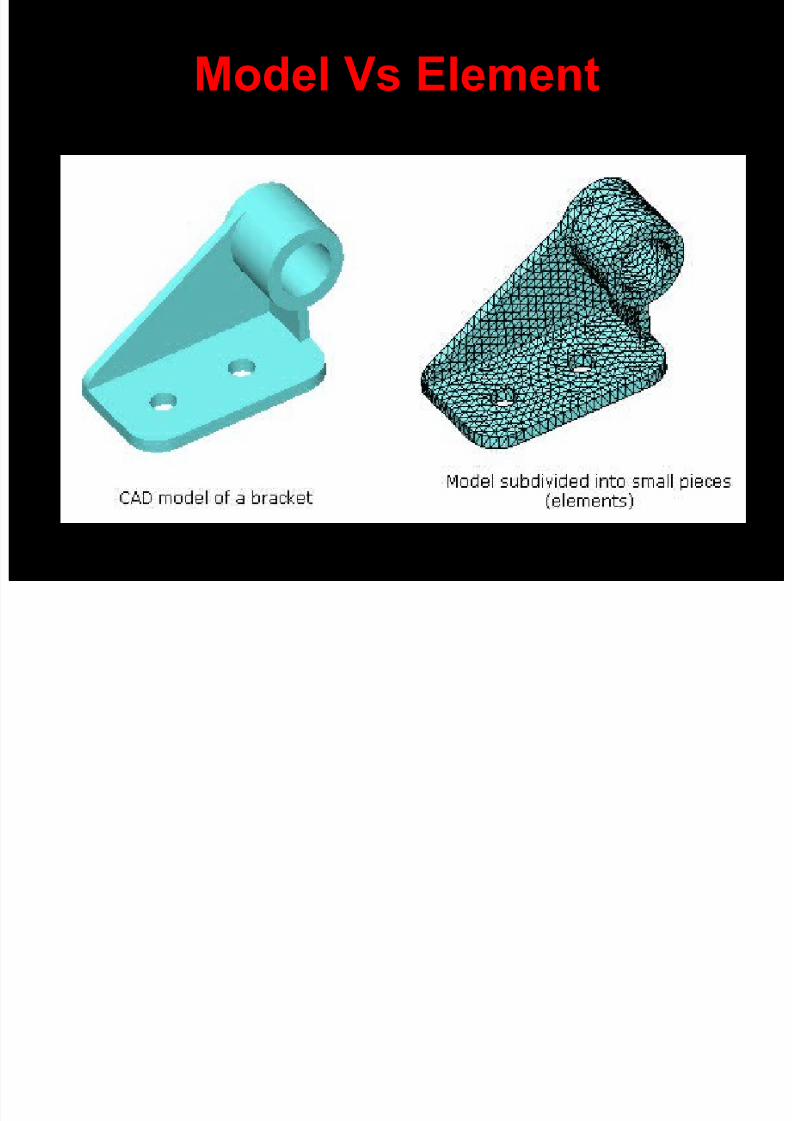
• FEM replaces a complex problem withmany simple problems.
• It divides the model into many small
pieces of simple shapes called elements.
Model Vs Element
8/8/2019 Trends of Cadcam
http://slidepdf.com/reader/full/trends-of-cadcam 124/155
10/06/10 [email protected]
Model Vs Element
Elements ?

8/8/2019 Trends of Cadcam
http://slidepdf.com/reader/full/trends-of-cadcam 125/155
10/06/10 [email protected]
• It Share common points called nodes.
• The behavior of these elements is well-knownunder all possible support and load scenarios.
• The motion of each node is fully described by
translations in the X, Y, and Z directions.
• These are called degrees of freedom (DOFs).
Analysis using FEM is called Finite Element
Analysis (FEA).
FEA Element

8/8/2019 Trends of Cadcam
http://slidepdf.com/reader/full/trends-of-cadcam 126/155
10/06/10 [email protected]
e e t
• A tetrahedral element.
Red dots represent
the element's nodes.• Element edges can be
curved or straight
The Steps?

8/8/2019 Trends of Cadcam
http://slidepdf.com/reader/full/trends-of-cadcam 127/155
10/06/10 [email protected]
p
• FEA formulates the equations governing the behavior of each element taking into consideration its connectivity toother elements. These equations relate thedisplacements to known material properties,restraints, and loads.
• The program organizes the equations into a large set of simultaneous algebraic equations. The solver finds thedisplacements in the X, Y, and Z directions at eachnode.
• Using the displacements, the program calculates thestrains in various directions. Finally, the program usesmathematical expressions to calculate stresses.
Analysis StepsSix Simple steps to complete Analysis

8/8/2019 Trends of Cadcam
http://slidepdf.com/reader/full/trends-of-cadcam 128/155
10/06/10 [email protected]
• Define material Properties
• Meshing
• Apply restraints
• Apply loads
• Solve the Part
• View the results
Six Simple steps to complete Analysis
Typical Analysis Result
Assembly of the Anchor plate

8/8/2019 Trends of Cadcam
http://slidepdf.com/reader/full/trends-of-cadcam 129/155
Better solutions
can be found at the root of theproblem.

8/8/2019 Trends of Cadcam
http://slidepdf.com/reader/full/trends-of-cadcam 130/155
Emerging Trends in CAD/CAM

8/8/2019 Trends of Cadcam
http://slidepdf.com/reader/full/trends-of-cadcam 131/155
10/06/10 [email protected]
g g
• Reverses Engineering
• Rapid Prototyping
What is reverse Engineering?Duplicating the Product with out Drawing or Documentation

8/8/2019 Trends of Cadcam
http://slidepdf.com/reader/full/trends-of-cadcam 132/155
10/06/10 [email protected]
• Duplicating the Product with out Drawing or DocumentationThrough Digitizing Technique.
• Get the Clouds of points Through Digitizing and use CAD todevelop the Surface
Reverse Engineering Process

8/8/2019 Trends of Cadcam
http://slidepdf.com/reader/full/trends-of-cadcam 133/155
10/06/10 [email protected]
Find a Product to Duplicate
Modify
Do research
Digitizing
Use CMM
Trace Co-ordinate
Save clouds of Pt.
CAD
Make proto type
Test/ R& D
PresentationGet Feed Back
Generate Surface/ Solid
Material Properties
Tailor the Design to meet
Restraints Of the Productionmethod and Reduce the
material cost
Plan
For Mfg.
PrototypeOriginal Part
8/8/2019 Trends of Cadcam
http://slidepdf.com/reader/full/trends-of-cadcam 134/155
Why Reverse Engineering

8/8/2019 Trends of Cadcam
http://slidepdf.com/reader/full/trends-of-cadcam 135/155
10/06/10 [email protected]
Duplicate and develop better productsThe original CAD model is not sufficient to
support modifications
The original supplier is unable to provide
additional parts
The OEM is not available
There is no Technical Documents
CNC DIGITIZING MACHINE
CNC DIGITIZING MACHINE

8/8/2019 Trends of Cadcam
http://slidepdf.com/reader/full/trends-of-cadcam 136/155
10/06/10 [email protected]
B A C
4.700 3.700 4.500
X Y Z
2.000 1.500 0.900
5 AXIS DIGITISING M/C
5 AXIS DIGITISING M/C

8/8/2019 Trends of Cadcam
http://slidepdf.com/reader/full/trends-of-cadcam 137/155
10/06/10 [email protected]
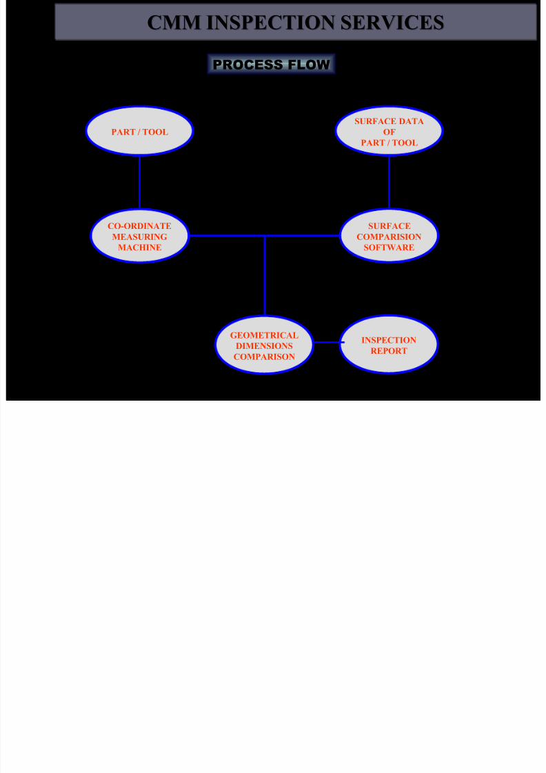
CMM FACILITIES

8/8/2019 Trends of Cadcam
http://slidepdf.com/reader/full/trends-of-cadcam 138/155
10/06/10 [email protected]
CMM FACILITIES
CMM NC-850 ZEISS
Bridge type:
Working area XYZ:850x700x600
Uncertainty : 2.5
Micron L/250
Minimum probe size:
0.8mm
Alloy wheel
Alloy wheel
Customer Application Examples

8/8/2019 Trends of Cadcam
http://slidepdf.com/reader/full/trends-of-cadcam 139/155
10/06/10 [email protected]
Manifold
ManifoldCustomer Application Examples

8/8/2019 Trends of Cadcam
http://slidepdf.com/reader/full/trends-of-cadcam 140/155
10/06/10 [email protected]
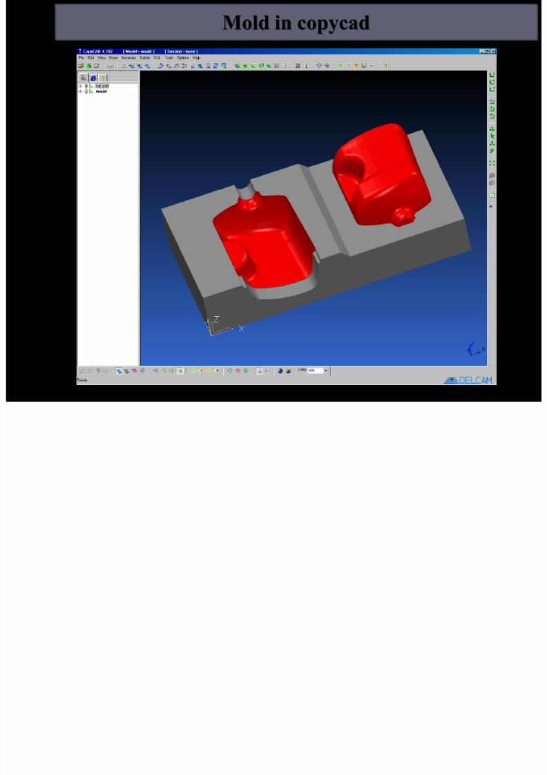
Manifold in copycad
Manifold in copycad
Customer Application Examples

8/8/2019 Trends of Cadcam
http://slidepdf.com/reader/full/trends-of-cadcam 141/155
10/06/10 [email protected]
8/8/2019 Trends of Cadcam
http://slidepdf.com/reader/full/trends-of-cadcam 142/155
REVERSE ENGINEERING
REVERSE ENGINEERING EXAMPLES
EXAMPLES

8/8/2019 Trends of Cadcam
http://slidepdf.com/reader/full/trends-of-cadcam 143/155
10/06/10 [email protected]
SCANNED
DATA (in the
form of points)
DOOR HEMMING FIXTURES
FOR
FIAT
SURFACE
DATA AFTER
SCANNING
DOOR HEMMING FIXTURES FOR FIAT
REVERSE ENGINEERING
REVERSE ENGINEERING EXAMPLES
EXAMPLES

8/8/2019 Trends of Cadcam
http://slidepdf.com/reader/full/trends-of-cadcam 144/155
10/06/10 [email protected]
REVERSE ENGINEERING
REVERSE ENGINEERING EXAMPLES
EXAMPLES
Customer Application Examples

8/8/2019 Trends of Cadcam
http://slidepdf.com/reader/full/trends-of-cadcam 145/155
10/06/10 [email protected]
DOOR OUTER FOR
TELCO JAMSHEDPUR
Aesthetic Design

8/8/2019 Trends of Cadcam
http://slidepdf.com/reader/full/trends-of-cadcam 146/155
10/06/10 [email protected]
• Inserting Image in CAD system
• Tracing India map image in CAD System
• Making Extrude Making Final Product• Exporting to CAM
• Cutter Parameter
• Making Tool Path
• Creating Core and cavity
• Mould Design and Making Mould
Student Project
Tracing India map image in CAD
System

8/8/2019 Trends of Cadcam
http://slidepdf.com/reader/full/trends-of-cadcam 147/155
10/06/10 [email protected]
System
Tracing Green line
Ready for Extrusion in CAD

8/8/2019 Trends of Cadcam
http://slidepdf.com/reader/full/trends-of-cadcam 148/155
10/06/10 [email protected]
Cutter Parameter

8/8/2019 Trends of Cadcam
http://slidepdf.com/reader/full/trends-of-cadcam 149/155
10/06/10 [email protected]
Exporting to CAM

8/8/2019 Trends of Cadcam
http://slidepdf.com/reader/full/trends-of-cadcam 150/155
10/06/10 [email protected]
Making Tool Path for Core andCavity

8/8/2019 Trends of Cadcam
http://slidepdf.com/reader/full/trends-of-cadcam 151/155
10/06/10 [email protected]
Ca y

8/8/2019 Trends of Cadcam
http://slidepdf.com/reader/full/trends-of-cadcam 152/155
DON’T WORK HARD

8/8/2019 Trends of Cadcam
http://slidepdf.com/reader/full/trends-of-cadcam 153/155
WORK SMART
GOAL
A Final Thought
8/8/2019 Trends of Cadcam
http://slidepdf.com/reader/full/trends-of-cadcam 154/155
g
Two stonecutters were
asked what they were
doing. The first said,
‘I’m cutting this stone
into blocks.’ The second
one replied, ‘I’m on a
team that’s building a
cathedral.’
— Old Story

8/8/2019 Trends of Cadcam
http://slidepdf.com/reader/full/trends-of-cadcam 155/155