troubleshooting hardware - cisco · troubleshooting hardware this chapter describes how to identify...
TRANSCRIPT
Send documenta t ion comments to mdsfeedback -doc@c i sco .com
Cisco MOL-9285-05
C H A P T E R 4
Troubleshooting HardwareThis chapter describes how to identify and resolve problems that might occur in the hardware components of the Cisco MDS 9000 Family. It includes the following sections:
• Overview, page 4-1
• Troubleshooting Startup Issues, page 4-2
• Troubleshooting Startup Issues, page 4-2
• Troubleshooting Power Supply Issues, page 4-3
• Troubleshooting Fan Issues, page 4-8
• Temperature Threshold Violations, page 4-11
• Troubleshooting Clock Module Issues, page 4-12
• Troubleshooting Other Hardware Issues, page 4-13
• Troubleshooting Supervisor Issues, page 4-14
• Troubleshooting Switching and Services Modules, page 4-21
OverviewThe key to success when troubleshooting the system hardware is to isolate the problem to a specific system component. The first step is to compare what the system is doing to what it should be doing. Because a startup problem can usually be attributed to a single component, it is more efficient to isolate the problem to a subsystem rather than troubleshoot each separate component in the system.
Problems with the initial power up are often caused by a module that is not firmly connected to the backplane or a power supply that has been disconnected from the power cord connector.
Overheating can also cause problems with the system, though typically only after the system has been operating for an extended period of time. The most common cause of overheating is the failure of a fan module.
The Cisco MDS 9000 Family includes the following subsystems on most chassis:
• Power supply— This includes the power supply fans.
• Fan module—The chassis fan module should operate whenever system power is on. You should see the Fan LED turn green and should hear the fan module to determine whether or not it is operating. If the Fan LED is red, this indicates that one or more fans in the fan module is not operating. You
4-1DS 9000 Family Troubleshooting Guide, Release 3.x
Send documenta t ion comments to mdsfeedback -doc@c i sco .com
Chapter 4 Troubleshooting HardwareTroubleshooting Startup Issues
should immediately contact your customer service representative. (See the “Steps to Perform Before Calling TAC” section on page A-1.) There are no installation adjustments that you can make if the fan module does not function properly at initial startup.
Note If you purchased Cisco support through a Cisco reseller, contact the reseller directly. If you purchased support directly from Cisco, contact Cisco Technical Support at this website: http://www.cisco.com/warp/public/687/Directory/DirTAC.shtm
• Supervisor module—The supervisor module contains the operating system software, so check your supervisor module if you have trouble with the system software. Status LEDs on the supervisor module indicate whether or not the supervisor module can initialize a switching module.
If you have a redundant supervisor module, refer to the following website for the latest Cisco MDS 9000 Family configuration guides for descriptions of how the redundant supervisor module comes online and how the software images are handled: http://www.cisco.com/univercd/cc/td/doc/product/sn5000/mds9000/index.htm.
• Switching module—Status LEDs on each module indicate if it has been initialized by the supervisor module. A module that is partially installed in the backplane can cause the system to halt.
SNMP TrapsYou can set SNMP traps to monitor fans, power supplies and temperature settings, or to test a call home application without risking adverse impact to your production SAN.
Use any of the following commands to set SNMP traps:
• test pfm test-SNMP-trap fan
• test pfm test-SNMP-trap powersupply
• test pfm test-SNMP-trap temp-sensor
Note You do not have to physically remove the fan or power supply, nor do you have to physically increase the temperature, to generate these traps.
Troubleshooting Startup IssuesLEDs indicate all system states in the startup sequence. By checking the LEDs, you can determine when and where the system failed in the startup sequence.
To identify startup problems, follow these steps:
Step 1 Turn on the power supplies by turning the switch to the on position (|). You should immediately hear the system fan module begin to operate. If not, see the “Troubleshooting Power Supply Issues” section on page 4-3.
Step 2 If you determine that the power supplies are functioning normally yet the fan module is faulty, see the “Troubleshooting Fan Issues” section on page 4-8.
4-2Cisco MDS 9000 Family Troubleshooting Guide, Release 3.x
OL-9285-05
Send documenta t ion comments to mdsfeedback -doc@c i sco .com
Chapter 4 Troubleshooting HardwareTroubleshooting Power Supply Issues
Step 3 Verify that the LEDs on the supervisor module display as follows:
a. The Status LED flashes orange once and stays orange during diagnostic boot tests. It turns green when the module is operational (online). If the system software cannot start up, this LED stays orange.
b. The System LED turns green, indicating that all chassis environmental monitors are reporting that the system is operational. If one or more of the environmental monitors reports a problem, the System LED is orange or red.
c. The Active LED turns green, indicating that the supervisor module is operational and active. If the supervisor module is in standby mode, the Active LED is orange.
d. Each Link LED flashes orange once and stays orange during diagnostic boot tests, and it turns green when the module is operational (online). If no signal is detected, the Link LED turns off. The link LED blinks orange if the port is bad.
If any LEDs on the supervisor module front panel are red or orange after the initialization time, see the “Troubleshooting Supervisor Issues” section on page 4-14. If you have a redundant supervisor module, refer to the following website for the latest Cisco MDS 9000 Family configuration guides for descriptions of the supervisor module LEDS, how the redundant supervisor module comes online, and how the software images are handled:
http://www.cisco.com/univercd/cc/td/doc/product/sn5000/mds9000/index.htm.
Step 4 Verify that the Status LEDs on the supervisor module and on each switching module are green when the supervisor module completes initialization. This LED indicates that the modules are receiving power, have been recognized by the supervisor module, and contain a valid Flash code version. This LED does not indicate the state of the individual interfaces on the switching modules. If a Status LED is red or orange, see the “Troubleshooting Supervisor Issues” section on page 4-14.
Step 5 Verify that the terminal is set correctly and that it is connected properly to the supervisor module console port if the boot information and system banner are not displayed.
Troubleshooting Power Supply IssuesThis section describes power supply problems and includes the following topics:
• All Power Supply LEDS Are Off, page 4-4
• Power Supply Input Ok LED is Red, page 4-5
• Power Supply Output Failed LED is On, page 4-6
• Power Supply Fan Ok LED is Red, page 4-6
4-3Cisco MDS 9000 Family Troubleshooting Guide, Release 3.x
OL-9285-05

Send documenta t ion comments to mdsfeedback -doc@c i sco .com
Chapter 4 Troubleshooting HardwareTroubleshooting Power Supply Issues
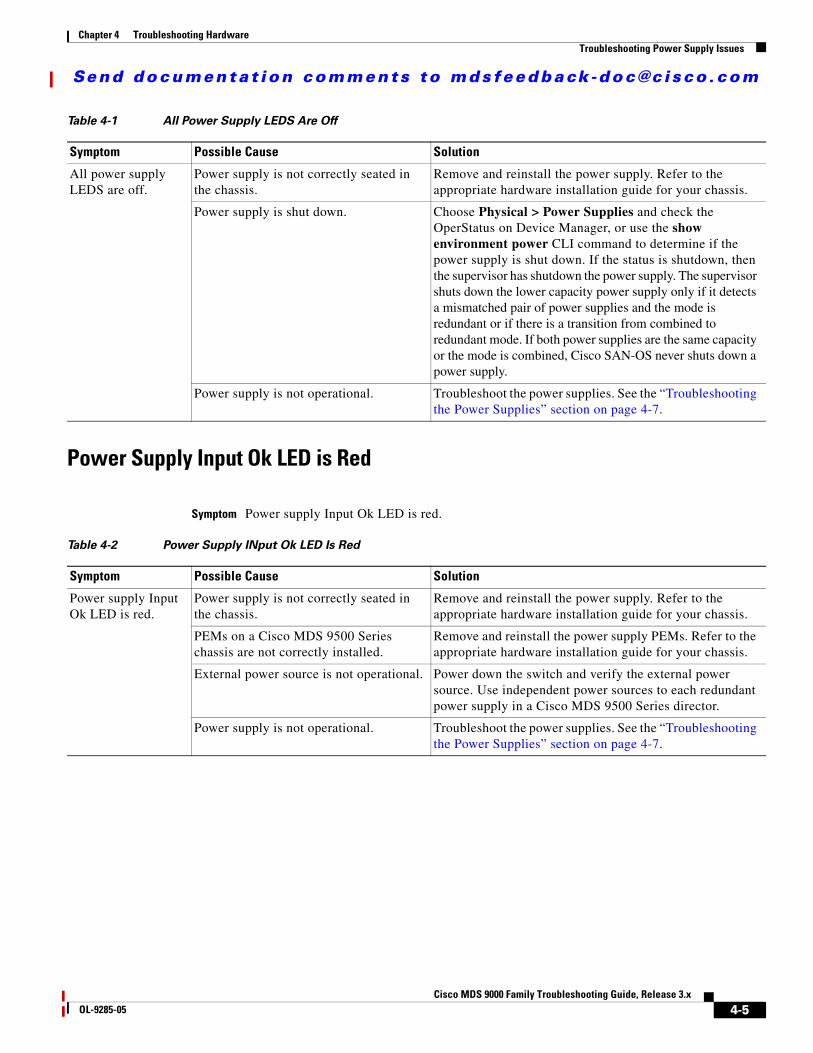
All Power Supply LEDS Are Off
Symptom All power supply LEDS are off.
The following system messages may be generated with this symptom:
Error Message PLATFORM-2-PS_FAIL: Power supply [dec] failed or shutdown (Serial No. [chars]).
Explanation Power supply failed or has been shut down.
Recommended Action Enter the show environment power and show platform internal info CLI commands or similar Fabric Manager or Device Manager command to collect more information. Refer to power supply documentation in the relevant hardware installation guide to learn more on increasing or decreasing power supply capacity and configuring power supplies.
Error Message PLATFORM-2-PS_MISMATCH: Detected power supply [chars]. This reduces the redundant power available to the system and can cause service disruptions (Serial No. [chars]).
Explanation Detected a new power supply that has reduced capacity compared to an existing power supply.
Recommended Action Refer to power supply document on increasing decreasing power supply capacity and configuring power supplies. Enter the show environment power and show platform internal info CLI command or similar Fabric Manager/Device Manager command to collect more information.
Error Message PLATFORM-5-PS_REMOVE: Power supply [dec] removed (Serial No. [chars]).
Explanation Power supply has been removed.
Recommended Action No action is required.
4-4Cisco MDS 9000 Family Troubleshooting Guide, Release 3.x
OL-9285-05
Send documenta t ion comments to mdsfeedback -doc@c i sco .com
Chapter 4 Troubleshooting HardwareTroubleshooting Power Supply Issues
Power Supply Input Ok LED is Red
Symptom Power supply Input Ok LED is red.
Table 4-1 All Power Supply LEDS Are Off
Symptom Possible Cause Solution
All power supply LEDS are off.
Power supply is not correctly seated in the chassis.
Remove and reinstall the power supply. Refer to the appropriate hardware installation guide for your chassis.
Power supply is shut down. Choose Physical > Power Supplies and check the OperStatus on Device Manager, or use the show environment power CLI command to determine if the power supply is shut down. If the status is shutdown, then the supervisor has shutdown the power supply. The supervisor shuts down the lower capacity power supply only if it detects a mismatched pair of power supplies and the mode is redundant or if there is a transition from combined to redundant mode. If both power supplies are the same capacity or the mode is combined, Cisco SAN-OS never shuts down a power supply.
Power supply is not operational. Troubleshoot the power supplies. See the “Troubleshooting the Power Supplies” section on page 4-7.
Table 4-2 Power Supply INput Ok LED Is Red
Symptom Possible Cause Solution
Power supply Input Ok LED is red.
Power supply is not correctly seated in the chassis.
Remove and reinstall the power supply. Refer to the appropriate hardware installation guide for your chassis.
PEMs on a Cisco MDS 9500 Series chassis are not correctly installed.
Remove and reinstall the power supply PEMs. Refer to the appropriate hardware installation guide for your chassis.
External power source is not operational. Power down the switch and verify the external power source. Use independent power sources to each redundant power supply in a Cisco MDS 9500 Series director.
Power supply is not operational. Troubleshoot the power supplies. See the “Troubleshooting the Power Supplies” section on page 4-7.
4-5Cisco MDS 9000 Family Troubleshooting Guide, Release 3.x
OL-9285-05
Send documenta t ion comments to mdsfeedback -doc@c i sco .com
Chapter 4 Troubleshooting HardwareTroubleshooting Power Supply Issues
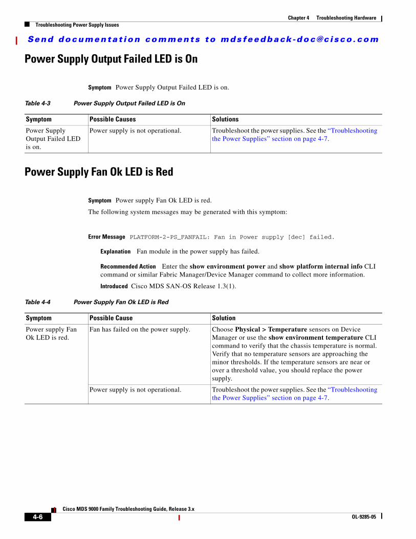
Power Supply Output Failed LED is On
Symptom Power Supply Output Failed LED is on.
Power Supply Fan Ok LED is Red
Symptom Power supply Fan Ok LED is red.
The following system messages may be generated with this symptom:
Error Message PLATFORM-2-PS_FANFAIL: Fan in Power supply [dec] failed.
Explanation Fan module in the power supply has failed.
Recommended Action Enter the show environment power and show platform internal info CLI command or similar Fabric Manager/Device Manager command to collect more information.
Introduced Cisco MDS SAN-OS Release 1.3(1).
Table 4-3 Power Supply Output Failed LED is On
Symptom Possible Causes Solutions
Power Supply Output Failed LED is on.
Power supply is not operational. Troubleshoot the power supplies. See the “Troubleshooting the Power Supplies” section on page 4-7.
Table 4-4 Power Supply Fan Ok LED is Red
Symptom Possible Cause Solution
Power supply Fan Ok LED is red.
Fan has failed on the power supply. Choose Physical > Temperature sensors on Device Manager or use the show environment temperature CLI command to verify that the chassis temperature is normal. Verify that no temperature sensors are approaching the minor thresholds. If the temperature sensors are near or over a threshold value, you should replace the power supply.
Power supply is not operational. Troubleshoot the power supplies. See the “Troubleshooting the Power Supplies” section on page 4-7.
4-6Cisco MDS 9000 Family Troubleshooting Guide, Release 3.x
OL-9285-05

Send documenta t ion comments to mdsfeedback -doc@c i sco .com
Chapter 4 Troubleshooting HardwareTroubleshooting Power Supply Issues
Troubleshooting the Power Supplies
To isolate a power supply problem, follow these steps:
Step 1 Verify that the Input Ok LED on the power supply is green. If the Input Ok LED is green, the AC or DC source is operational and the power supply is functional.
Step 2 If the Input Ok LED is off, first ensure that the power supply is flush with the chassis. Turn the power switch off, tighten the captive screw(s), and then turn the power switch on (|). If the Input Ok LED remains off, there might be a problem with the AC source or the DC source, or with the power cable.
a. Turn off the power to the switch by pressing or turning both power switches to 0, connect the power cord to another power source if one is available, and turn the power on. If the Input Ok LED is now green, the problem was the first power source.
b. If the Input Ok LED fails to light after you connect the power supply to a new power source, replace the power cord and turn the switch on. If the Input Ok LED lights at this point, return the first power cord for replacement.
c. If the Input Ok LED still fails to light when the switch is connected to a different power source with a new power cord, the power supply is probably faulty. If a second power supply is available, install it in the second power supply bay and contact your customer service representative for further instructions.
Note If you purchased Cisco support through a Cisco reseller, contact the reseller directly. If you purchased support directly from Cisco, contact Cisco Technical Support at this URL: http://www.cisco.com/warp/public/687/Directory/DirTAC.shtm
Step 3 Repeat Step 1 if you have a second (redundant) power supply.
Step 4 Choose Physical > Power Supplies on Device Manager or use the show environment power command to verify the status of your power supplies. (See Example 4-1.)
Example 4-1 Output of show environment power
switch# show environment power -----------------------------------------------------PS Model Power Power Status (Watts) (Amp @42V) -----------------------------------------------------1 DS-CAC-1900W 1019.34 24.27 ok 2 DS-CAC-1900W 1019.34 24.27 ok
Mod Model Power Power Power Power Status Requested Requested Allocated Allocated (Watts) (Amp @42V) (Watts) (Amp @42V) --- ------------------- ------- ---------- --------- ---------- ----------3 DS-X9016 220.08 5.24 220.08 5.24 powered-up4 DS-X9308-SMIP 210.00 5.00 210.00 5.00 powered-up5 DS-X9530-SF1-K9 220.08 5.24 220.08 5.24 powered-up
Power Usage Summary:------------------Power Supply redundancy mode: redundant
Total Power Capacity 1019.34 W
4-7Cisco MDS 9000 Family Troubleshooting Guide, Release 3.x
OL-9285-05
Send documenta t ion comments to mdsfeedback -doc@c i sco .com
Chapter 4 Troubleshooting HardwareTroubleshooting Fan Issues
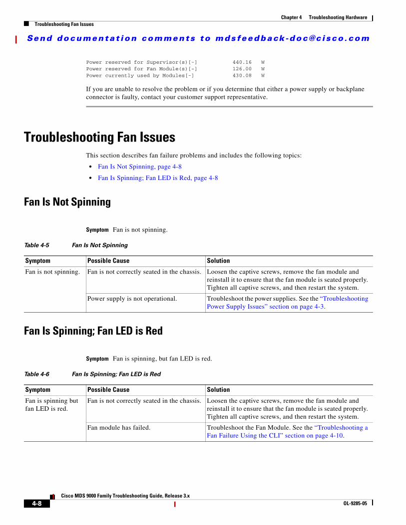
Power reserved for Supervisor(s)[-] 440.16 WPower reserved for Fan Module(s)[-] 126.00 WPower currently used by Modules[-] 430.08 W
If you are unable to resolve the problem or if you determine that either a power supply or backplane connector is faulty, contact your customer support representative.
Troubleshooting Fan IssuesThis section describes fan failure problems and includes the following topics:
• Fan Is Not Spinning, page 4-8
• Fan Is Spinning; Fan LED is Red, page 4-8
Fan Is Not Spinning
Symptom Fan is not spinning.
Fan Is Spinning; Fan LED is Red
Symptom Fan is spinning, but fan LED is red.
Table 4-5 Fan Is Not Spinning
Symptom Possible Cause Solution
Fan is not spinning. Fan is not correctly seated in the chassis. Loosen the captive screws, remove the fan module and reinstall it to ensure that the fan module is seated properly. Tighten all captive screws, and then restart the system.
Power supply is not operational. Troubleshoot the power supplies. See the “Troubleshooting Power Supply Issues” section on page 4-3.
Table 4-6 Fan Is Spinning; Fan LED is Red
Symptom Possible Cause Solution
Fan is spinning but fan LED is red.
Fan is not correctly seated in the chassis. Loosen the captive screws, remove the fan module and reinstall it to ensure that the fan module is seated properly. Tighten all captive screws, and then restart the system.
Fan module has failed. Troubleshoot the Fan Module. See the “Troubleshooting a Fan Failure Using the CLI” section on page 4-10.
4-8Cisco MDS 9000 Family Troubleshooting Guide, Release 3.x
OL-9285-05

Send documenta t ion comments to mdsfeedback -doc@c i sco .com
Chapter 4 Troubleshooting HardwareTroubleshooting Fan Issues
Troubleshooting a Fan Failure Using Device Manager
To troubleshoot a fan module problem using Device Manager, follow these steps:
Step 1 Choose Physical > Fan. You see the Fan Status dialog box.
Step 2 If the OperStatus is failure, one or more fans are not operational. Replace the failed fan module before your switch overheats. You should see the following system message in the switch log:
Error Message PLATFORM-1-CASA_FAN_FAIL: Fan module [dec] Failed.
Explanation Fan module failed and needs to be replaced. This can lead to overheating and temperature alarms.
Recommended Action Enter the show platform internal info command or similar Fabric Manager/Device Manager command to collect more information.
Step 3 If the OperStatus is absent, the fan module has been removed. As soon as the fan module is removed, Cisco SAN-OS starts a five-minute countdown.
Caution If the fan module is not reinserted within five minutes, the entire switch is shutdown.
Software reads a byte on the SEEPROM to determine if the fan module is present. If the fan module is partially inserted or if software is unable to access the SEEPROM on the fan module for any other reason, then Cisco SAN-OS cannot distinguish this case from a real fan module removal. The switch will be shut down in five minutes. The following priority 0 syslog messages are printed every five seconds:
Error Message PLATFORM-0-FAIL_REMOVED: Fan module removed. Fan module has been absent for [dec] seconds.
Explanation Fan module was removed. This could lead to temperature alarms.
Recommended Action Replace the fan module immediately.
Step 4 Remove and reinstall or replace the fan module. If the Fan LED is still red, the system detects a fan module failure. Contact your customer service representative for instructions.
Note If you purchased Cisco support through a Cisco reseller, contact the reseller directly. If you purchased support directly from Cisco, contact Cisco Technical Support at this URL: http://www.cisco.com/warp/public/687/Directory/DirTAC.shtm
4-9Cisco MDS 9000 Family Troubleshooting Guide, Release 3.x
OL-9285-05
Send documenta t ion comments to mdsfeedback -doc@c i sco .com
Chapter 4 Troubleshooting HardwareTroubleshooting Fan Issues
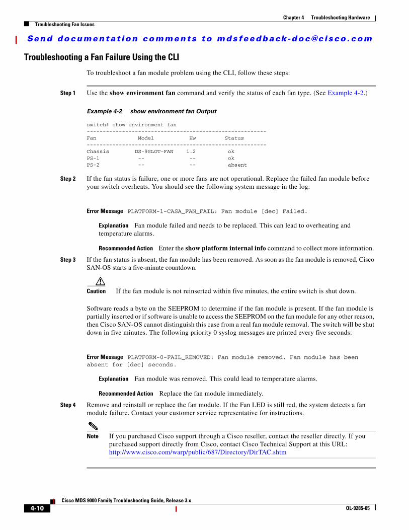
Troubleshooting a Fan Failure Using the CLI
To troubleshoot a fan module problem using the CLI, follow these steps:
Step 1 Use the show environment fan command and verify the status of each fan type. (See Example 4-2.)
Example 4-2 show environment fan Output
switch# show environment fan --------------------------------------------------------Fan Model Hw Status --------------------------------------------------------Chassis DS-9SLOT-FAN 1.2 ok PS-1 -- -- ok PS-2 -- -- absent
Step 2 If the fan status is failure, one or more fans are not operational. Replace the failed fan module before your switch overheats. You should see the following system message in the log:
Error Message PLATFORM-1-CASA_FAN_FAIL: Fan module [dec] Failed.
Explanation Fan module failed and needs to be replaced. This can lead to overheating and temperature alarms.
Recommended Action Enter the show platform internal info command to collect more information.
Step 3 If the fan status is absent, the fan module has been removed. As soon as the fan module is removed, Cisco SAN-OS starts a five-minute countdown.
Caution If the fan module is not reinserted within five minutes, the entire switch is shut down.
Software reads a byte on the SEEPROM to determine if the fan module is present. If the fan module is partially inserted or if software is unable to access the SEEPROM on the fan module for any other reason, then Cisco SAN-OS cannot distinguish this case from a real fan module removal. The switch will be shut down in five minutes. The following priority 0 syslog messages are printed every five seconds:
Error Message PLATFORM-0-FAIL_REMOVED: Fan module removed. Fan module has been absent for [dec] seconds.
Explanation Fan module was removed. This could lead to temperature alarms.
Recommended Action Replace the fan module immediately.
Step 4 Remove and reinstall or replace the fan module. If the Fan LED is still red, the system detects a fan module failure. Contact your customer service representative for instructions.
Note If you purchased Cisco support through a Cisco reseller, contact the reseller directly. If you purchased support directly from Cisco, contact Cisco Technical Support at this URL: http://www.cisco.com/warp/public/687/Directory/DirTAC.shtm
4-10Cisco MDS 9000 Family Troubleshooting Guide, Release 3.x
OL-9285-05

Send documenta t ion comments to mdsfeedback -doc@c i sco .com
Chapter 4 Troubleshooting HardwareTemperature Threshold Violations
Temperature Threshold ViolationsEach module in the chassis has at least two temperature sensors. Each temperature sensor is configured with a minor and a major threshold. Example 4-3 gives the show environment temperature CLI command sample output. It shows how temperature information can be retrieved from the switch. Choose Physical > Temperature Sensors on Device Manager to view a similar output.
Example 4-3 Output of show environment temperature Command
switch# show environment temperature ---------------------------------------------------------------Module Sensor MajorThresh MinorThres CurTemp Status (Celsius) (Celsius) (Celsius) ---------------------------------------------------------------4 Outlet 75 60 36 ok4 Intake 65 50 29 ok
5 Outlet 75 60 35 ok5 Intake 65 50 34 ok
6 Outlet 75 60 35 ok6 Intake 65 50 34 ok
9 Outlet 75 60 45 ok9 Intake 65 50 40 ok
The intake sensor, located at the airflow intake on the module, is the most critical indicator of module temperature. All Cisco SAN-OS actions are taken when the major threshold of an intake sensor is exceeded.
A minor threshold violation or a major threshold violation on an outlet sensor results in the following system message:
Error Message PLATFORM-0-MOD_TEMPMAJALRM: Module [dec] reported major temperature alarm.
Explanation Module in the slot exceeded a major temperature threshold.
Recommended Action Enter the show environment temperature CLI command or choose Physical > Temperature Sensors on Device Manager to collect more information.
This violation also generates a Call Home event and an SNMP notification.
A major temperature threshold violation on a module intake sensor results in the following system message:
Error Message PLATFORM-0-MOD_TEMPSHUTDOWN: Module [dec] powered down due to major temperature alarm.
Explanation Module shutdown due to temperature exceeding major threshold.
Recommended Action Enter show environment temperature CLI command or similar Fabric Manager/Device Manager command to collect more information.
4-11Cisco MDS 9000 Family Troubleshooting Guide, Release 3.x
OL-9285-05
Send documenta t ion comments to mdsfeedback -doc@c i sco .com
Chapter 4 Troubleshooting HardwareTroubleshooting Clock Module Issues
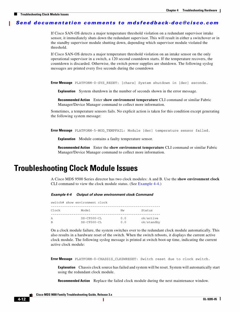
If Cisco SAN-OS detects a major temperature threshold violation on a redundant supervisor intake sensor, it immediately shuts down the redundant supervisor. This will result in either a switchover or in the standby supervisor module shutting down, depending which supervisor module violated the threshold.
If Cisco SAN-OS detects a major temperature threshold violation on an intake sensor on the only operational supervisor in a switch, a 120 second countdown starts. If the temperature recovers, the countdown is discarded. Otherwise, the switch power supplies are shutdown. The following syslog messages are printed every five seconds during the countdown
Error Message PLATFORM-0-SYS_RESET: [chars] System shutdown in [dec] seconds.
Explanation System shutdown in the number of seconds shown in the error message.
Recommended Action Enter show environment temperature CLI command or similar Fabric Manager/Device Manager command to collect more information.
Sometimes, a temperature sensors fails. No explicit action is taken for this condition except generating the following system message:
Error Message PLATFORM-5-MOD_TEMPFAIL: Module [dec] temperature sensor failed.
Explanation Module contains a faulty temperature sensor.
Recommended Action Enter the show environment temperature CLI command or similar Fabric Manager/Device Manager command to collect more information.
Troubleshooting Clock Module Issues A Cisco MDS 9500 Series director has two clock modules: A and B. Use the show environment clock CLI command to view the clock module status. (See Example 4-4.)
Example 4-4 Output of show environment clock Command
switch# show environment clock ----------------------------------------------------------Clock Model Hw Status ----------------------------------------------------------A DS-C9500-CL 0.0 ok/activeB DS-C9500-CL 0.0 ok/standby
On a clock module failure, the system switches over to the redundant clock module automatically. This also results in a hardware reset of the switch. When the switch reboots, it displays the current active clock module. The following syslog message is printed at switch boot-up time, indicating the current active clock module:
Error Message PLATFORM-0-CHASSIS_CLKSWRESET: Switch reset due to clock switch.
Explanation Chassis clock source has failed and system will be reset. System will automatically start using the redundant clock module.
Recommended Action Replace the failed clock module during the next maintenance window.
4-12Cisco MDS 9000 Family Troubleshooting Guide, Release 3.x
OL-9285-05
Send documenta t ion comments to mdsfeedback -doc@c i sco .com
Chapter 4 Troubleshooting HardwareTroubleshooting Other Hardware Issues
Typically, clock module A is the active clock. On a failure of clock module A, clock module B becomes the active clock. Refer to the hardware installation guide for your platform at the following website to replace a clock module.
http://www.cisco.com/en/US/products/hw/ps4159/ps4358/prod_installation_guides_list.html
Troubleshooting Other Hardware Issues
Note To issue commands with the internal keyword, you must have an account that is a member of the network-admin group.
To identify a hardware issue with a module using the CLI, follow these steps:
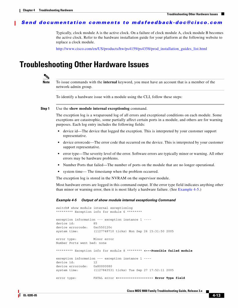
Step 1 Use the show module internal exceptionlog command.
The exception log is a wraparound log of all errors and exceptional conditions on each module. Some exceptions are catastrophic, some partially affect certain ports in a module, and others are for warning purposes. Each log entry includes the following fields:
• device id—The device that logged the exception. This is interpreted by your customer support representative.
• device errorcode—The error code that occurred on the device. This is interpreted by your customer support representative.
• error type—The severity level of the error. Software errors are typically minor or warning. All other errors may be hardware problems.
• Number Ports that failed—The number of ports on the module that are no longer operational.
• system time— The timestamp when the problem occurred.
The exception log is stored in the NVRAM on the supervisor module.
Most hardware errors are logged in this command output. If the error type field indicates anything other than minor or warning error, then it is most likely a hardware failure. (See Example 4-5.)
Example 4-5 Output of show module internal exceptionlog Command
switch# show module internal exceptionlog ********* Exception info for module 6 ********
exception information --- exception instance 1 ----device id: 85device errorcode: 0xc550120csystem time: (1127748710 ticks) Mon Sep 26 15:31:50 2005
error type: Minor errorNumber Ports went bad: none
********* Exception info for module 8 ******** <---Possible failed module
exception information --- exception instance 1 ----device id: 12device errorcode: 0x80000080system time: (1127843531 ticks) Tue Sep 27 17:52:11 2005
error type: FATAL error <------------------- Error Type field
4-13Cisco MDS 9000 Family Troubleshooting Guide, Release 3.x
OL-9285-05
Send documenta t ion comments to mdsfeedback -doc@c i sco .com
Chapter 4 Troubleshooting HardwareTroubleshooting Supervisor Issues
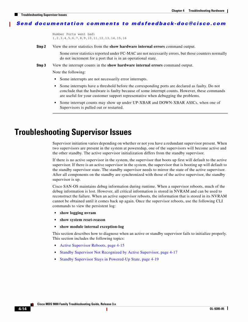
Number Ports went bad:1,2,3,4,5,6,7,8,9,10,11,12,13,14,15,16
Step 2 View the error statistics from the show hardware internal errors command output.
Some error statistics reported under FC-MAC are not necessarily errors, but those counters normally do not increment for a port that is in an operational state.
Step 3 View the interrupt counts in the show hardware internal errors command output.
Note the following:
• Some interrupts are not necessarily error interrupts.
• Some interrupts have a threshold before the corresponding ports are declared as faulty. Do not conclude that the hardware is faulty because of some interrupt counts. However, these commands are useful for your customer support representative when debugging the problems.
• Some interrupt counts may show up under UP-XBAR and DOWN-XBAR ASICs, when one of Supervisors is pulled out or restarted.
Troubleshooting Supervisor IssuesSupervisor initiation varies depending on whether or not you have a redundant supervisor present. When two supervisors are present in the system at poweredup, one of the supervisors will become active and the other standby. The active supervisor initialization differs from the standby supervisor.
If there is no active supervisor in the system, the supervisor that boots up first will default to the active supervisor. If there is an active supervisor in the system, the supervisor that is booting up will default to the standby supervisor state. The standby supervisor needs to mirror the state of the active supervisor. After all components on the standby are synchronized with those of the active supervisor, the standby supervisor is up.
Cisco SAN-OS maintains debug information during runtime. When a supervisor reboots, much of the debug information is lost. However, all critical information is stored in NVRAM and can be used to reconstruct the failure. When an active supervisor reboots, the information that is stored in its NVRAM cannot be obtained until it comes back up again. Once the supervisor reboots, use the following CLI commands to view the persistent log:
• show logging nvram
• show system reset-reason
• show module internal exception-log
This section describes how to diagnose when an active or standby supervisor fails to initialize properly. This section includes the following topics:
• Active Supervisor Reboots, page 4-15
• Standby Supervisor Not Recognized by Active Supervisor, page 4-17
• Standby Supervisor Stays in Powered-Up State, page 4-19
4-14Cisco MDS 9000 Family Troubleshooting Guide, Release 3.x
OL-9285-05

Send documenta t ion comments to mdsfeedback -doc@c i sco .com
Chapter 4 Troubleshooting HardwareTroubleshooting Supervisor Issues
Active Supervisor Reboots
Symptom Active supervisor reboots.
Example 4-6 displays the reason for the recent when a supervisor module reboots after a process crash.
Example 4-6 Reset Reason for Supervisor Reboot Caused by Failed Process
switch# show system reset-reason ----- reset reason for module 6 -----1) At 94009 usecs after Tue Sep 27 18:52:13 2005 Reason: Reset triggered due to HA policy of Reset Service: Service "xbar" <------------------ Process that caused the reboot Version: 2.1(2)
Example 4-7 displays the system messages on the standby supervisor when a supervisor reboots after a process crash.
Example 4-7 System Messages for Supervisor Reboot Caused by Failed Process
Switch# show logging2005 Sep 27 18:58:05 172.20.150.204 %SYSMGR-3-SERVICE_CRASHED: Service "xbar" (PID 1225) hasn't caught signal 9 (no core).2005 Sep 27 18:58:06 172.20.150.204 %SYSMGR-3-SERVICE_CRASHED: Service "xbar" (PID 2349) hasn't caught signal 9 (no core).2005 Sep 27 18:58:06 172.20.150.204 %SYSMGR-3-SERVICE_CRASHED: Service "xbar" (PID 2352) hasn't caught signal 9 (no core).
Table 4-7 Active Supervisor Reboots
Symptom Possible Cause Solution
Active supervisor reboots.
Supervisor process crashed, resulting in a supervisor reload.
Use the show system reset-reason CLI command to view the cause of the reset after the supervisor reboots. (See Example 4-6.) If you have a standby supervisor, the standby is now the active supervisor. Display the system message log on the standby supervisor to see the same information. (See Example 4-7.)
Use the show process log CLI command to view a list of process restarts.
Runtime diagnostics failure detected. Use the show module internal exceptionlog CLI command on the standby supervisor to view the cause of the reset after the supervisor reboots. (See Example 4-8.) If you have a standby supervisor, the standby is now the active supervisor. Display the system message log on the standby supervisor to see the same information. See (Example 4-9.) Optionally, when the supervisor reboots, use the show system reset-reason CLI command to view this same information.
See also the “Troubleshooting Cisco SAN-OS Software System Reboots” section on page 2-13.
4-15Cisco MDS 9000 Family Troubleshooting Guide, Release 3.x
OL-9285-05
Send documenta t ion comments to mdsfeedback -doc@c i sco .com
Chapter 4 Troubleshooting HardwareTroubleshooting Supervisor Issues
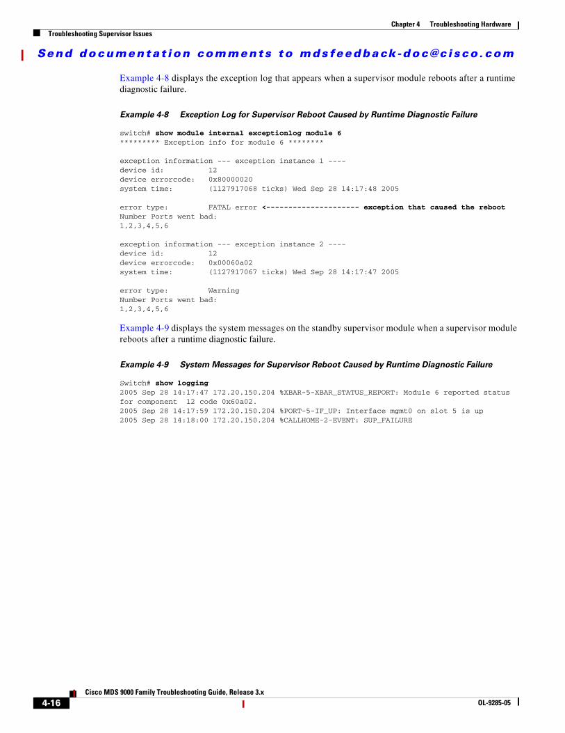
Example 4-8 displays the exception log that appears when a supervisor module reboots after a runtime diagnostic failure.
Example 4-8 Exception Log for Supervisor Reboot Caused by Runtime Diagnostic Failure
switch# show module internal exceptionlog module 6********* Exception info for module 6 ********
exception information --- exception instance 1 ----device id: 12device errorcode: 0x80000020system time: (1127917068 ticks) Wed Sep 28 14:17:48 2005
error type: FATAL error <--------------------- exception that caused the rebootNumber Ports went bad:1,2,3,4,5,6
exception information --- exception instance 2 ----device id: 12device errorcode: 0x00060a02system time: (1127917067 ticks) Wed Sep 28 14:17:47 2005
error type: WarningNumber Ports went bad:1,2,3,4,5,6
Example 4-9 displays the system messages on the standby supervisor module when a supervisor module reboots after a runtime diagnostic failure.
Example 4-9 System Messages for Supervisor Reboot Caused by Runtime Diagnostic Failure
Switch# show logging2005 Sep 28 14:17:47 172.20.150.204 %XBAR-5-XBAR_STATUS_REPORT: Module 6 reported status for component 12 code 0x60a02.2005 Sep 28 14:17:59 172.20.150.204 %PORT-5-IF_UP: Interface mgmt0 on slot 5 is up 2005 Sep 28 14:18:00 172.20.150.204 %CALLHOME-2-EVENT: SUP_FAILURE
4-16Cisco MDS 9000 Family Troubleshooting Guide, Release 3.x
OL-9285-05
Send documenta t ion comments to mdsfeedback -doc@c i sco .com
Chapter 4 Troubleshooting HardwareTroubleshooting Supervisor Issues
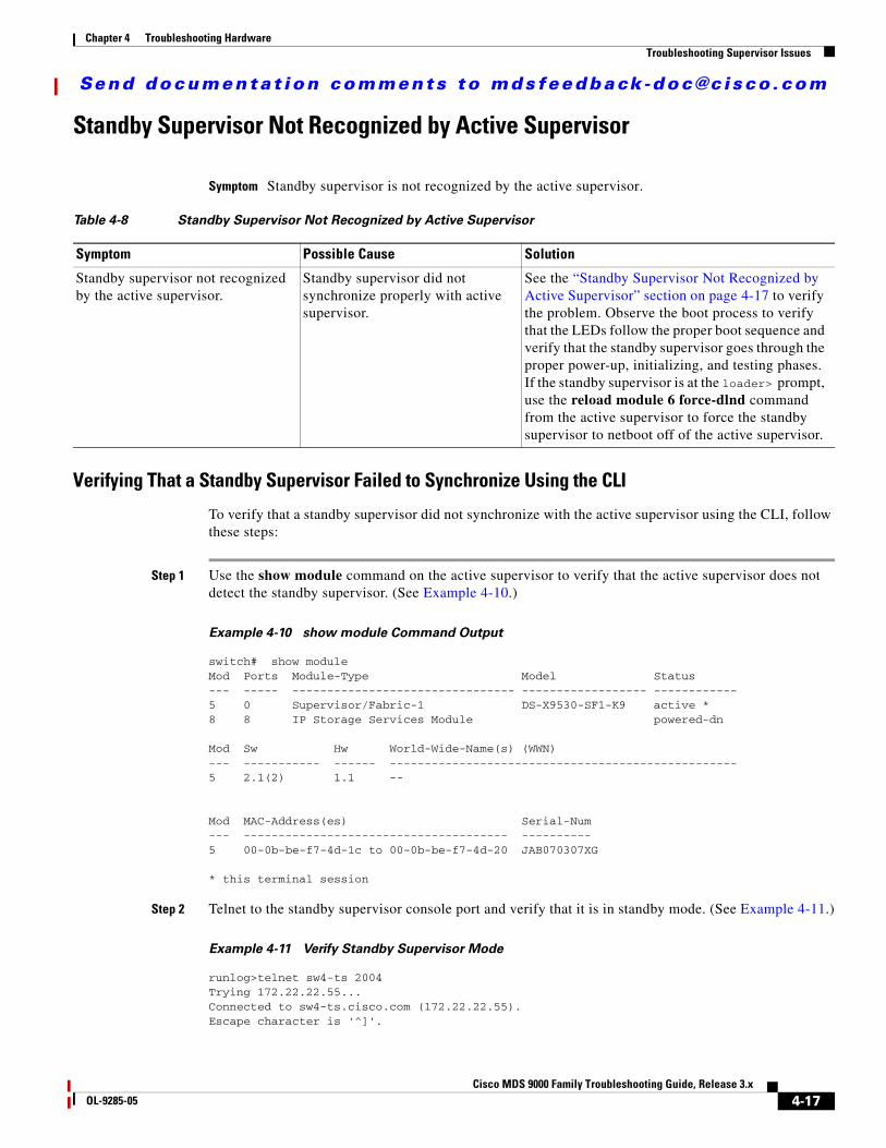
Standby Supervisor Not Recognized by Active Supervisor
Symptom Standby supervisor is not recognized by the active supervisor.
Verifying That a Standby Supervisor Failed to Synchronize Using the CLI
To verify that a standby supervisor did not synchronize with the active supervisor using the CLI, follow these steps:
Step 1 Use the show module command on the active supervisor to verify that the active supervisor does not detect the standby supervisor. (See Example 4-10.)
Example 4-10 show module Command Output
switch# show module Mod Ports Module-Type Model Status--- ----- -------------------------------- ------------------ ------------5 0 Supervisor/Fabric-1 DS-X9530-SF1-K9 active *8 8 IP Storage Services Module powered-dn
Mod Sw Hw World-Wide-Name(s) (WWN)--- ----------- ------ --------------------------------------------------5 2.1(2) 1.1 --
Mod MAC-Address(es) Serial-Num--- -------------------------------------- ----------5 00-0b-be-f7-4d-1c to 00-0b-be-f7-4d-20 JAB070307XG
* this terminal session
Step 2 Telnet to the standby supervisor console port and verify that it is in standby mode. (See Example 4-11.)
Example 4-11 Verify Standby Supervisor Mode
runlog>telnet sw4-ts 2004Trying 172.22.22.55...Connected to sw4-ts.cisco.com (172.22.22.55).Escape character is '^]'.
Table 4-8 Standby Supervisor Not Recognized by Active Supervisor
Symptom Possible Cause Solution
Standby supervisor not recognized by the active supervisor.
Standby supervisor did not synchronize properly with active supervisor.
See the “Standby Supervisor Not Recognized by Active Supervisor” section on page 4-17 to verify the problem. Observe the boot process to verify that the LEDs follow the proper boot sequence and verify that the standby supervisor goes through the proper power-up, initializing, and testing phases. If the standby supervisor is at the loader> prompt, use the reload module 6 force-dlnd command from the active supervisor to force the standby supervisor to netboot off of the active supervisor.
4-17Cisco MDS 9000 Family Troubleshooting Guide, Release 3.x
OL-9285-05

Send documenta t ion comments to mdsfeedback -doc@c i sco .com
Chapter 4 Troubleshooting HardwareTroubleshooting Supervisor Issues
MDS Switch login: adminPassword: Cisco Storage Area Networking Operating System (SAN-OS) SoftwareTAC support: http://www.cisco.com/tacCopyright (c) 2002-2005, Cisco Systems, Inc. All rights reserved.The copyrights to certain works contained herein are owned byother third parties and are used and distributed under license.Some parts of this software are covered under the GNU PublicLicense. A copy of the license is available athttp://www.gnu.org/licenses/gpl.html.switch(standby)#
Step 3 Use the show system redundancy status command on the active supervisor to verify that the standby supervisor did not complete the synchronization phase with the active supervisor.
switch# show system redundancy status Redundancy mode--------------- administrative: HA operational: None
This supervisor (sup-1)----------------------- Redundancy state: Active Supervisor state: Active Internal state: Active with HA standby
Other supervisor (sup-2)------------------------ Redundancy state: Standby Supervisor state: HA standby Internal state: HA synchronization in progress
The most likely reason for the synchronization to stall is that one of the software components on the standby supervisor failed to synchronize its state with the active supervisor.
Step 4 Use the show system internal sysmgr gsyncstats command on the active supervisor to determine which processes did not synchronize on the standby supervisor.
switch# show system internal sysmgr gsyncstats Name Gsync done Gsync time(sec)---------------- ---------- -------------aaa 1 0ExceptionLog 1 0platform 1 1radius 1 0securityd 1 0SystemHealth 1 0tacacs 0 N/Aacl 1 0ascii-cfg 1 1bios_daemon 0 N/Abootvar 1 0callhome 1 0capability 1 0cdp 1 0cfs 1 0cimserver 1 0cimxmlserver 0 N/Aconfcheck 1 0core-dmon 1 0core-client 0 N/Adevice-alias 1 0
4-18Cisco MDS 9000 Family Troubleshooting Guide, Release 3.x
OL-9285-05

Send documenta t ion comments to mdsfeedback -doc@c i sco .com
Chapter 4 Troubleshooting HardwareTroubleshooting Supervisor Issues
dpvm 0 N/Adstats 1 0epld_upgrade 0 N/Aepp 1 1
Step 5 Use the show system internal sysmgr service all command on the standby supervisor to determine whether or not any process is experiencing excessive restarts. (See Example 4-12.)
Note This command may not be available if the standby supervisor is at the loader> prompt.
Example 4-12 Finding Excessive Restarts
switch(standby)# show system internal sysmgr service allName UUID PID SAP state Start count------------ -------- ------ ----- ----- -----------aaa 0x000000B5 1458 111 s0009 1ExceptionLog 0x00000050 [NA] [NA] s0002 Noneplatform 0x00000018 1064 39 s0009 1radius 0x000000B7 1457 113 s0009 1securityd 0x0000002A 1456 55 s0009 1vsan 0x00000029 1436 15 s0009 1vshd 0x00000028 1408 37 s0009 1wwn 0x00000030 1435 114 s0009 1xbar 0x00000017 [NA] [NA] s0017 23xbar_client 0x00000049 1434 917 s0009 1
Looking at the standby supervisor in Example 4-12 shows that the crossbar (xbar) software component has been restarted 23 times. This has probably prevented the standby from initializing properly.
Step 6 Use the reload module command to restart the standby supervisor. If the restart fails, use the reload module 6 force-dlnd command from the active supervisor to force the standby supervisor to netboot off of the active supervisor.
Standby Supervisor Stays in Powered-Up State
Symptom Standby supervisor stays in powered-up state.
Table 4-9
Symptom Possible Cause Solution
Standby supervisor stays in powered-up state.
Standby supervisor did not synchronize properly with active supervisor.
See the “Verifying That a Standby Supervisor Is in the Powered-Up State Using Device Manager” section on page 4-20 or the “Verifying That a Standby Supervisor Is in Powered-Up State Using the CLI” section on page 4-20.
4-19Cisco MDS 9000 Family Troubleshooting Guide, Release 3.x
OL-9285-05
Send documenta t ion comments to mdsfeedback -doc@c i sco .com
Chapter 4 Troubleshooting HardwareTroubleshooting Supervisor Issues
Verifying That a Standby Supervisor Is in the Powered-Up State Using Device Manager
To verify that a standby supervisor is in the powered-up state using Device Manager, follow these steps:
Step 1 Choose Physical > Modules.... and verify that the operational status of the standby supervisor (OperStatus) is PoweredUp.
Step 2 Right-click the standby supervisor and select Reset from the drop-down menu to restart the standby supervisor.
Verifying That a Standby Supervisor Is in Powered-Up State Using the CLI
To verify that a standby supervisor is in the powered-up state using the CLI, follow these steps:
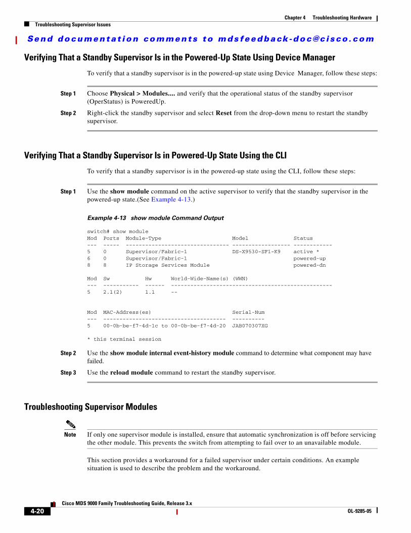
Step 1 Use the show module command on the active supervisor to verify that the standby supervisor in the powered-up state.(See Example 4-13.)
Example 4-13 show module Command Output
switch# show module Mod Ports Module-Type Model Status--- ----- -------------------------------- ------------------ ------------5 0 Supervisor/Fabric-1 DS-X9530-SF1-K9 active *6 0 Supervisor/Fabric-1 powered-up8 8 IP Storage Services Module powered-dn
Mod Sw Hw World-Wide-Name(s) (WWN)--- ----------- ------ --------------------------------------------------5 2.1(2) 1.1 --
Mod MAC-Address(es) Serial-Num--- -------------------------------------- ----------5 00-0b-be-f7-4d-1c to 00-0b-be-f7-4d-20 JAB070307XG
* this terminal session
Step 2 Use the show module internal event-history module command to determine what component may have failed.
Step 3 Use the reload module command to restart the standby supervisor.
Troubleshooting Supervisor Modules
Note If only one supervisor module is installed, ensure that automatic synchronization is off before servicing the other module. This prevents the switch from attempting to fail over to an unavailable module.
This section provides a workaround for a failed supervisor under certain conditions. An example situation is used to describe the problem and the workaround.
4-20Cisco MDS 9000 Family Troubleshooting Guide, Release 3.x
OL-9285-05
Send documenta t ion comments to mdsfeedback -doc@c i sco .com
Chapter 4 Troubleshooting HardwareTroubleshooting Switching and Services Modules
In this sample case, the supervisor failed when the standby was reloaded or when the supervisor was replaced with a new one. It was discovered that the failed supervisor either had its version of code changed, or the running configuration on the active supervisor was not saved with the appropriate boot parameters. In either case, the problem was mismatched code on the active and standby supervisors. One clue that indicated the mismatched code was a heartbeat error on the active supervisor. Because of this error, the current Flash images were unable to be copied from the active supervisor to the standby.
The workaround was to copy the images to CompactFlash, switch consoles, and load code from CompactFlash onto the second supervisor. The second supervisor was at a loader prompt, which is indicative of missing boot statements. When a dir slot0: CLI command was entered, none of the images appeared. This may have been the result of mismatched images on supervisors or to not having current images in Flash memory on the supervisor. Entering a copy slot0: bootflash: CLI command copied the images anyway. Once the images were loaded on the second supervisor and the boot statements were confirmed and saved on the active supervisor, the supervisor loaded and came up in standby-ha mode.
Troubleshooting Switching and Services ModulesThis section describes problems with switching and services modules and includes the following topics and symptoms:
• Overview of Module Status, page 4-21
• Module Initialization Overview, page 4-22
• Troubleshooting Powered-Down Modules, page 4-26
• Troubleshooting Reloaded Modules, page 4-31
• Troubleshooting Modules in an Unknown State, page 4-34
• Troubleshooting Modules Not Detected by the Supervisor, page 4-35
• Reinitializing a Failed Module Using Fabric Manager, page 4-36
• Reinitializing a Failed Module Using the CLI, page 4-37
• Module Resets, page 4-38
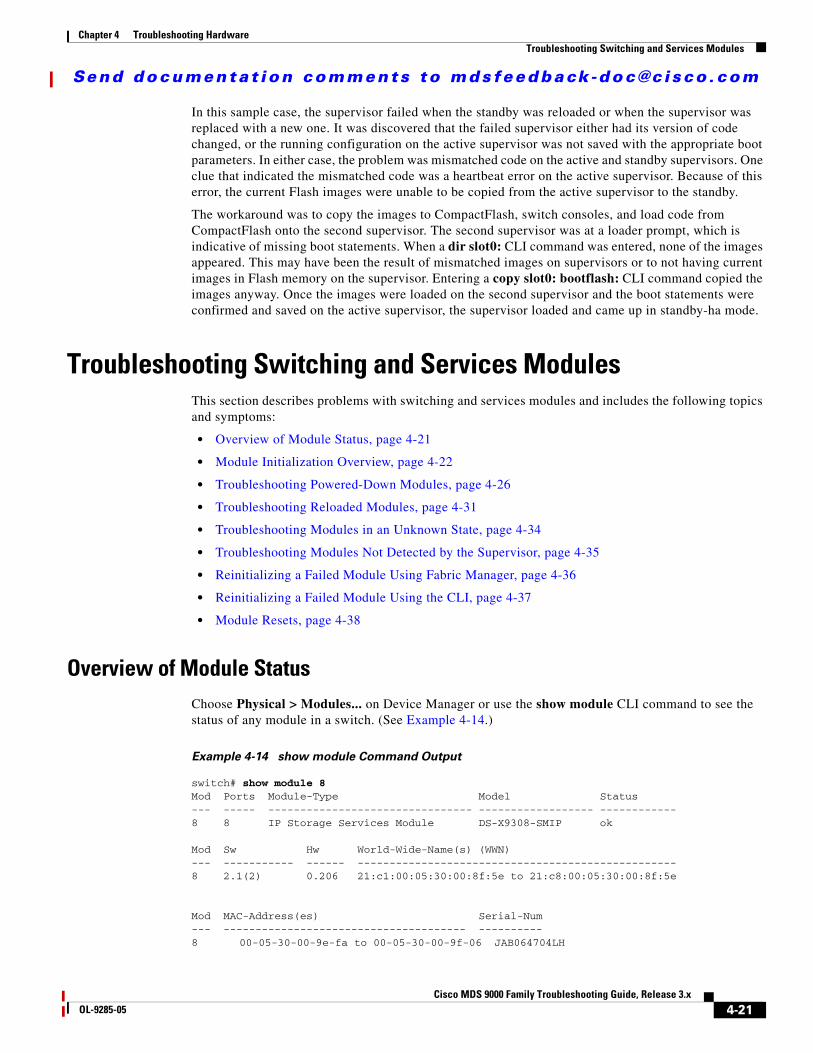
Overview of Module StatusChoose Physical > Modules... on Device Manager or use the show module CLI command to see the status of any module in a switch. (See Example 4-14.)
Example 4-14 show module Command Output
switch# show module 8Mod Ports Module-Type Model Status--- ----- -------------------------------- ------------------ ------------8 8 IP Storage Services Module DS-X9308-SMIP ok
Mod Sw Hw World-Wide-Name(s) (WWN)--- ----------- ------ --------------------------------------------------8 2.1(2) 0.206 21:c1:00:05:30:00:8f:5e to 21:c8:00:05:30:00:8f:5e
Mod MAC-Address(es) Serial-Num--- -------------------------------------- ----------8 00-05-30-00-9e-fa to 00-05-30-00-9f-06 JAB064704LH
4-21Cisco MDS 9000 Family Troubleshooting Guide, Release 3.x
OL-9285-05
Send documenta t ion comments to mdsfeedback -doc@c i sco .com
Chapter 4 Troubleshooting HardwareTroubleshooting Switching and Services Modules
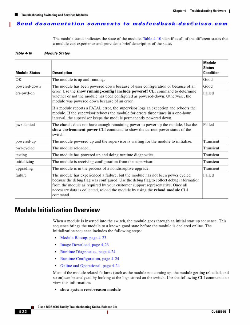
The module status indicates the state of the module. Table 4-10 identifies all of the different states that a module can experience and provides a brief description of the state.
Module Initialization OverviewWhen a module is inserted into the switch, the module goes through an initial start up sequence. This sequence brings the module to a known good state before the module is declared online. The initialization sequence includes the following steps:
• Module Bootup, page 4-23
• Image Download, page 4-23
• Runtime Diagnostics, page 4-24
• Runtime Configuration, page 4-24
• Online and Operational, page 4-24
Most of the module related failures (such as the module not coming up, the module getting reloaded, and so on) can be analyzed by looking at the logs stored on the switch. Use the following CLI commands to view this information:
• show system reset-reason module
Table 4-10 Module States
Module Status Description
Module Status Condition
OK The module is up and running. Good
powered-down The module has been powered down because of user configuration or because of an error. Use the show running-config | include poweroff CLI command to determine whether or not the module has been configured as powered-down. Otherwise, the module was powered down because of an error.
If a module reports a FATAL error, the supervisor logs an exception and reboots the module. If the supervisor reboots the module for errors three times in a one-hour interval, the supervisor keeps the module permanently powered down.
Good
err-pwd-dn Failed
pwr-denied The chassis does not have enough remaining power to power up the module. Use the show environment power CLI command to show the current power status of the switch.
Failed
powered-up The module powered up and the supervisor is waiting for the module to initialize. Transient
pwr-cycled The module reloaded. Transient
testing The module has powered up and doing runtime diagnostics. Transient
initializing The module is receiving configuration from the supervisor. Transient
upgrading The module is in the process of a nondisruptive upgrade. Transient
failure The module has experienced a failure, but the module has not been power cycled because the debug flag was configured. Use the debug flag to collect debug information from the module as required by your customer support representative. Once all necessary data is collected, reload the module by using the reload module CLI command.
Failed
4-22Cisco MDS 9000 Family Troubleshooting Guide, Release 3.x
OL-9285-05
Send documenta t ion comments to mdsfeedback -doc@c i sco .com
Chapter 4 Troubleshooting HardwareTroubleshooting Switching and Services Modules
• show version
• show logging
• show module internal exception-log
• show module internal event-history module
• show module internal event-history errors
• show platform internal event-history errors
• show platform internal event-history module
Module Bootup
When a module is inserted into the switch, the supervisor puts the module in powered-up state. In this state, the supervisor waits for the module to boot and send its identification to the active supervisor.
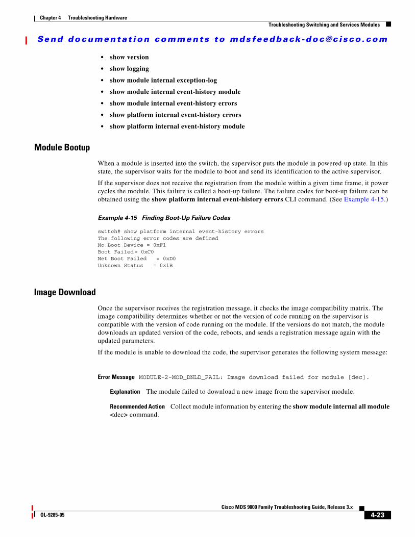
If the supervisor does not receive the registration from the module within a given time frame, it power cycles the module. This failure is called a boot-up failure. The failure codes for boot-up failure can be obtained using the show platform internal event-history errors CLI command. (See Example 4-15.)
Example 4-15 Finding Boot-Up Failure Codes
switch# show platform internal event-history errorsThe following error codes are definedNo Boot Device = 0xF1Boot Failed= 0xC0Net Boot Failed = 0xD0Unknown Status = 0x1B
Image Download
Once the supervisor receives the registration message, it checks the image compatibility matrix. The image compatibility determines whether or not the version of code running on the supervisor is compatible with the version of code running on the module. If the versions do not match, the module downloads an updated version of the code, reboots, and sends a registration message again with the updated parameters.
If the module is unable to download the code, the supervisor generates the following system message:
Error Message MODULE-2-MOD_DNLD_FAIL: Image download failed for module [dec].
Explanation The module failed to download a new image from the supervisor module.
Recommended Action Collect module information by entering the show module internal all module <dec> command.
4-23Cisco MDS 9000 Family Troubleshooting Guide, Release 3.x
OL-9285-05

Send documenta t ion comments to mdsfeedback -doc@c i sco .com
Chapter 4 Troubleshooting HardwareTroubleshooting Switching and Services Modules
In addition, the module generates a system message indicating the exact reason why the image download failed:
Error Message IMAGE_DNLD-SLOT#-2-ADDON_IMG_DNLD_FAILED: Module image download process failed. [chars].
Explanation The add-on image download to the module failed. This module is not operational until an add-on image has been successfully installed.
Recommended Action Verify the location and version of your module image. Enter install module CLI command or similar Fabric Manager/Device Manager command to download a new module image.
If the image download fails, the supervisor power cycles the module. Choose Logs > Switch Resident > Syslog > Since Reboot in Device Manager or use the show logging CLI command to view the failure messages.
Runtime Diagnostics
After the module successfully registers with the supervisor, the module checks the hardware. If this fails, the module reports the error to the supervisor and generates the following system message:
Error Message MODULE-2-MOD_DIAG_FAIL: Module [dec] reported failure on ports [dec]/[dec]-[dec]/[dec] ([chars]) due to [chars] in device [dec] (device error [hex]).
Explanation The module reported a failure in the runtime diagnostic. Module manager is going to power cycle the module.
Recommended Action Collect information about the module by entering the show module internal all module CLI command.
In addition, this information is stored in the exception log (which is persistent across reboots). The supervisor then power cycles the module. Choose Logs > Switch Resident > Syslog > Since Reboot in Device Manager or use the show logging and show module internal exception-log module CLI commands to retrieve failure information.
Runtime Configuration
After the runtime diagnostics complete successfully, the module informs the supervisor that it is ready for configuration. Individual supervisor components configure the module. If any component reports a problem during this stage, the supervisor reboots the module. Use the show module internal event-history module CLI command to determine which component reported the problem.
Online and Operational
After all the supervisor components have configured the module, the module goes to the ok state. In this state, the module is online and operational. The supervisor continues to monitor the module periodically to verify correct operation. The following events are monitored:
• Heartbeat message—Sent between the supervisor and the module to verify that the module is running.
4-24Cisco MDS 9000 Family Troubleshooting Guide, Release 3.x
OL-9285-05
Send documenta t ion comments to mdsfeedback -doc@c i sco .com
Chapter 4 Troubleshooting HardwareTroubleshooting Switching and Services Modules
• Online health management (OHMS)—Sent from the supervisor to all the ports in the module to verify that traffic is flowing properly.
In addition, the module monitors itself and generates an exception if it detects an anomalous condition. If the exception is a FATAL error, the module is power cycled. Use the following CLI commands to view the conditions leading up to the problem:
• show logging
• show module diag
• show module internal exception-log module
• show module internal event-history module
• show hardware internal errors
Analyzing The Logs
In some instances, you may need to check other internal logs to verify the cause of a problem. You can use the state transition log and the error log in these instances. These logs may hold information not present in the system messages or in the exception log because of interactions between the module and the supervisor. The state transition log is sorted in ascending manner (that is, the latest state is at the end of the log). The error log is sorted in descending manner (that is, the latest error is at the beginning of the log).
Use the show module internal event-history module CLI command to view the state transition log for a module. Use the show module internal event-history errors CLI command to view the error log.
The state transition log indicates the current state of a given module. (See Example 4-16.) Each element of the transition log contains the following information:
• Timestamp
• Node that triggered the state transition
• Module state prior to transition
• Event that occurred
• Current state of module
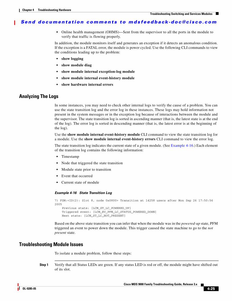
Example 4-16 State Transition Log
7) FSM:<ID(2): Slot 8, node 0x0800> Transition at 14258 usecs after Mon Sep 26 17:50:56 2005 Previous state: [LCM_ST_LC_POWERED_UP] Triggered event: [LCM_EV_PFM_LC_STATUS_POWERED_DOWN] Next state: [LCM_ST_LC_NOT_PRESENT]
Based on the above state transition you can infer that when the module was in the powered-up state, PFM triggered an event to power down the module. This trigger caused the state machine to go to the not present state.
Troubleshooting Module Issues
To isolate a module problem, follow these steps:
Step 1 Verify that all Status LEDs are green. If any status LED is red or off, the module might have shifted out of its slot.
4-25Cisco MDS 9000 Family Troubleshooting Guide, Release 3.x
OL-9285-05

Send documenta t ion comments to mdsfeedback -doc@c i sco .com
Chapter 4 Troubleshooting HardwareTroubleshooting Switching and Services Modules
Step 2 Reseat the module until both ejector levers are at 90 degrees to the rear of the chassis.
Step 3 Tighten the captive screws at the left and right of the module front panel.
Step 4 Restart the system.
If the Status LED on a switching module is orange, the module might be busy or disabled. Refer to the following website for the latest Cisco MDS 9000 Family configuration guides to configure or enable the interfaces:http://www.cisco.com/univercd/cc/td/doc/product/sn5000/mds9000/index.htm.After the system reinitializes the interfaces, the Status LED on the module should be green.
Step 5 If the module does not transition into the online state, see the symptoms listed in this section.
If you are unable to resolve a problem with the startup, gather the information listed under Appendix A, “Before Contacting Technical Support” and contact your technical support representative for assistance as directed in the “Obtaining Documentation, Obtaining Support, and Security Guidelines” section on page xxxii.
Troubleshooting Powered-Down Modules
Symptom Module is in the powered-down state.
The following system messages may be present if a module fails to power up:
Error Message PLATFORM-2-PFM_LC_BOOT_DEV_ABSENT: No bootflash found in Module [dec].
Explanation No bootflash found.
Recommended Action Put bootflash in the module and try again.
Error Message PLATFORM-2-PFM_LC_BOOT_DEV_FAIL: BAD Bootflash found in Module [dec].
Explanation Bad bootflash found.
Recommended Action Replace the bootflash in the module and try again.
Error Message PLATFORM-2-PFM_LC_NETBOOT_FAIL: Netboot for Module [dec] failed.
Explanation Netboot failed.
Recommended Action Replace the BIOS in the module. See the “Troubleshooting Cisco SAN-OS Software System Reboots” section on page 2-13.
4-26Cisco MDS 9000 Family Troubleshooting Guide, Release 3.x
OL-9285-05

Send documenta t ion comments to mdsfeedback -doc@c i sco .com
Chapter 4 Troubleshooting HardwareTroubleshooting Switching and Services Modules
Error Message PLATFORM-2-PFM_LC_REGISTRATION_FAIL: Could not register with Module [dec].
Explanation Module registration failed.
Recommended Action Replace the module.
Error Message PLATFORM-2-PFM_LC_STATUS: Module [dec] powered up with [dec] status.
Explanation Status for module that failed registration.
Recommended Action Replace the module.
Error Message PLATFORM-3-MOD_PWRFAIL: Module [dec] failed to power up (Serial No. [chars]).
Explanation The module failed to power up.
Recommended Action Enter the show platform internal all module [dec] CLI command to collect more information.
Introduced Cisco MDS SAN-OS Release 1.2(2a).
Error Message PLATFORM-3-MOD_PWRIDPROMFAIL: Module [dec] failed to power up due to idprom read error.
Explanation The module cannot be powered up because of an IDPROM read error.
Recommended Action Enter the show platform internal all module [dec] and show module internal all module [dec] show sprom module [dec][dec] CLI command to read module IDPROM contents to collect more information.
Error Message PLATFORM-5-MOD_PWRDN: Module [dec] powered down (Serial No. [chars]).
Explanation The module is powered down.
Enter the show module, show platform internal all module[dec] and show module internal all module [dec] CLI command to collect more information if you suspect module has been powered down due to errors.
4-27Cisco MDS 9000 Family Troubleshooting Guide, Release 3.x
OL-9285-05

Send documenta t ion comments to mdsfeedback -doc@c i sco .com
Chapter 4 Troubleshooting HardwareTroubleshooting Switching and Services Modules
Diagnosing a Powered-Down Module
To diagnose the reason for a powered-down module using the CLI, follow these steps:
Step 1 Use the show system reset-reason module to show the reason for the last reload of the module.
Step 2 Use the show module command to verify the status of the module.
switch# show module Mod Ports Module-Type Model Status--- ----- -------------------------------- ------------------ ------------5 0 Supervisor/Fabric-1 DS-X9530-SF1-K9 ha-standby6 0 Supervisor/Fabric-1 DS-X9530-SF1-K9 active *8 8 IP Storage Services Module powered-dn
Mod Sw Hw World-Wide-Name(s) (WWN)--- ----------- ------ ------------------------------------5 2.1(2) 1.1 -- 6 2.1(2) 0.602 --
Table 4-11 Module is in the Powered-Down State
Symptom Possible Cause Solution
Module is in powered-down state.
Module experienced boot-up failures.
Choose Logs > Switch Resident > Syslog > Sever Events on Device Manager or use the show logging CLI command to verify bootup problems. Right-click the module in Device Manager and select Reset or use the reload module CLI command to restart the module. See the “Reinitializing a Failed Module Using Fabric Manager” section on page 4-36 or the “Reinitializing a Failed Module Using the CLI” section on page 4-37.
Module failed to register with the supervisor.
Use the show module internal event-history module CLI command and look for:
Triggered event: [LCM_EV_LCP_REGISTRATION_TIMEOUT]
to verify that the module did not register. Right-click the module in Device Manager and select Reset or use the reload module CLI command to restart the module. See the “Reinitializing a Failed Module Using Fabric Manager” section on page 4-36 or the “Reinitializing a Failed Module Using the CLI” section on page 4-37.
Module failed to connect to fabric.
Use the show system internal xbar internal event-history module CLI command and look for :
Triggered event: [XBM_MOD_EV_SYNC_FAILED]
to verify that the module could not connect to the fabric. Right-click the module in Device Manager and select Reset or use the reload module CLI command to restart the module. See the “Reinitializing a Failed Module Using Fabric Manager” section on page 4-36 or the “Reinitializing a Failed Module Using the CLI” section on page 4-37.
Supervisor failed to configure the module.
Verify the cause of the failure. See the “Diagnosing a Powered-Down Module” section on page 4-28. Right-click the module in Device Manager and select Reset or use the reload module CLI command to restart the module. See the “Reinitializing a Failed Module Using Fabric Manager” section on page 4-36 or the “Reinitializing a Failed Module Using the CLI” section on page 4-37.
4-28Cisco MDS 9000 Family Troubleshooting Guide, Release 3.x
OL-9285-05
Send documenta t ion comments to mdsfeedback -doc@c i sco .com
Chapter 4 Troubleshooting HardwareTroubleshooting Switching and Services Modules
Mod MAC-Address(es) Serial-Num--- -------------------------------------- ----------5 00-0b-be-f7-4d-1c to 00-0b-be-f7-4d-20 JAB070307XG6 00-05-30-00-93-7e to 00-05-30-00-93-82 JAB0637059v
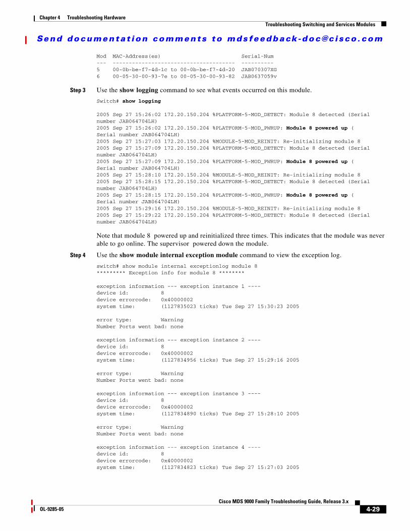
Step 3 Use the show logging command to see what events occurred on this module.
Switch# show logging
2005 Sep 27 15:26:02 172.20.150.204 %PLATFORM-5-MOD_DETECT: Module 8 detected (Serial number JAB064704LH)2005 Sep 27 15:26:02 172.20.150.204 %PLATFORM-5-MOD_PWRUP: Module 8 powered up (Serial number JAB064704LH)2005 Sep 27 15:27:03 172.20.150.204 %MODULE-5-MOD_REINIT: Re-initializing module 82005 Sep 27 15:27:09 172.20.150.204 %PLATFORM-5-MOD_DETECT: Module 8 detected (Serial number JAB064704LH)2005 Sep 27 15:27:09 172.20.150.204 %PLATFORM-5-MOD_PWRUP: Module 8 powered up (Serial number JAB064704LH)2005 Sep 27 15:28:10 172.20.150.204 %MODULE-5-MOD_REINIT: Re-initializing module 82005 Sep 27 15:28:15 172.20.150.204 %PLATFORM-5-MOD_DETECT: Module 8 detected (Serial number JAB064704LH)2005 Sep 27 15:28:15 172.20.150.204 %PLATFORM-5-MOD_PWRUP: Module 8 powered up (Serial number JAB064704LH)2005 Sep 27 15:29:16 172.20.150.204 %MODULE-5-MOD_REINIT: Re-initializing module 82005 Sep 27 15:29:22 172.20.150.204 %PLATFORM-5-MOD_DETECT: Module 8 detected (Serial number JAB064704LH)
Note that module 8 powered up and reinitialized three times. This indicates that the module was never able to go online. The supervisor powered down the module.
Step 4 Use the show module internal exception module command to view the exception log.
switch# show module internal exceptionlog module 8********* Exception info for module 8 ********
exception information --- exception instance 1 ----device id: 8device errorcode: 0x40000002system time: (1127835023 ticks) Tue Sep 27 15:30:23 2005
error type: WarningNumber Ports went bad: none
exception information --- exception instance 2 ----device id: 8device errorcode: 0x40000002system time: (1127834956 ticks) Tue Sep 27 15:29:16 2005
error type: WarningNumber Ports went bad: none
exception information --- exception instance 3 ----device id: 8device errorcode: 0x40000002system time: (1127834890 ticks) Tue Sep 27 15:28:10 2005
error type: WarningNumber Ports went bad: none
exception information --- exception instance 4 ----device id: 8device errorcode: 0x40000002system time: (1127834823 ticks) Tue Sep 27 15:27:03 2005
4-29Cisco MDS 9000 Family Troubleshooting Guide, Release 3.x
OL-9285-05
Send documenta t ion comments to mdsfeedback -doc@c i sco .com
Chapter 4 Troubleshooting HardwareTroubleshooting Switching and Services Modules
Note that the time when the module was reinitialized (from system messages) and the time when the exceptions were raised (in the exception log) are correlated. This means that device ID:8 had errors while bringing the module up.
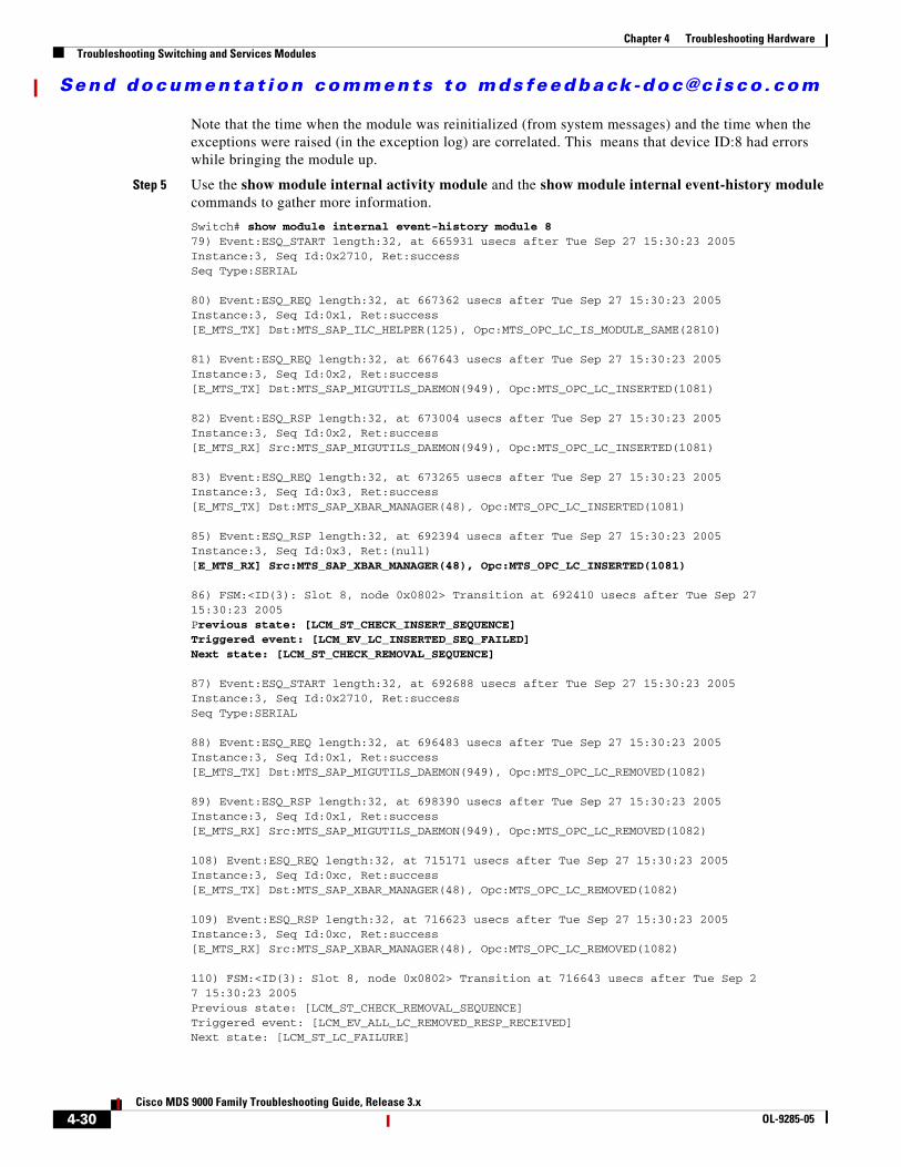
Step 5 Use the show module internal activity module and the show module internal event-history module commands to gather more information.
Switch# show module internal event-history module 879) Event:ESQ_START length:32, at 665931 usecs after Tue Sep 27 15:30:23 2005Instance:3, Seq Id:0x2710, Ret:successSeq Type:SERIAL
80) Event:ESQ_REQ length:32, at 667362 usecs after Tue Sep 27 15:30:23 2005Instance:3, Seq Id:0x1, Ret:success[E_MTS_TX] Dst:MTS_SAP_ILC_HELPER(125), Opc:MTS_OPC_LC_IS_MODULE_SAME(2810)
81) Event:ESQ_REQ length:32, at 667643 usecs after Tue Sep 27 15:30:23 2005Instance:3, Seq Id:0x2, Ret:success[E_MTS_TX] Dst:MTS_SAP_MIGUTILS_DAEMON(949), Opc:MTS_OPC_LC_INSERTED(1081)
82) Event:ESQ_RSP length:32, at 673004 usecs after Tue Sep 27 15:30:23 2005Instance:3, Seq Id:0x2, Ret:success[E_MTS_RX] Src:MTS_SAP_MIGUTILS_DAEMON(949), Opc:MTS_OPC_LC_INSERTED(1081)
83) Event:ESQ_REQ length:32, at 673265 usecs after Tue Sep 27 15:30:23 2005Instance:3, Seq Id:0x3, Ret:success[E_MTS_TX] Dst:MTS_SAP_XBAR_MANAGER(48), Opc:MTS_OPC_LC_INSERTED(1081)
85) Event:ESQ_RSP length:32, at 692394 usecs after Tue Sep 27 15:30:23 2005Instance:3, Seq Id:0x3, Ret:(null)[E_MTS_RX] Src:MTS_SAP_XBAR_MANAGER(48), Opc:MTS_OPC_LC_INSERTED(1081)
86) FSM:<ID(3): Slot 8, node 0x0802> Transition at 692410 usecs after Tue Sep 2715:30:23 2005Previous state: [LCM_ST_CHECK_INSERT_SEQUENCE]Triggered event: [LCM_EV_LC_INSERTED_SEQ_FAILED]Next state: [LCM_ST_CHECK_REMOVAL_SEQUENCE]
87) Event:ESQ_START length:32, at 692688 usecs after Tue Sep 27 15:30:23 2005Instance:3, Seq Id:0x2710, Ret:successSeq Type:SERIAL
88) Event:ESQ_REQ length:32, at 696483 usecs after Tue Sep 27 15:30:23 2005Instance:3, Seq Id:0x1, Ret:success[E_MTS_TX] Dst:MTS_SAP_MIGUTILS_DAEMON(949), Opc:MTS_OPC_LC_REMOVED(1082)
89) Event:ESQ_RSP length:32, at 698390 usecs after Tue Sep 27 15:30:23 2005Instance:3, Seq Id:0x1, Ret:success[E_MTS_RX] Src:MTS_SAP_MIGUTILS_DAEMON(949), Opc:MTS_OPC_LC_REMOVED(1082)
108) Event:ESQ_REQ length:32, at 715171 usecs after Tue Sep 27 15:30:23 2005Instance:3, Seq Id:0xc, Ret:success[E_MTS_TX] Dst:MTS_SAP_XBAR_MANAGER(48), Opc:MTS_OPC_LC_REMOVED(1082)
109) Event:ESQ_RSP length:32, at 716623 usecs after Tue Sep 27 15:30:23 2005Instance:3, Seq Id:0xc, Ret:success[E_MTS_RX] Src:MTS_SAP_XBAR_MANAGER(48), Opc:MTS_OPC_LC_REMOVED(1082)
110) FSM:<ID(3): Slot 8, node 0x0802> Transition at 716643 usecs after Tue Sep 27 15:30:23 2005Previous state: [LCM_ST_CHECK_REMOVAL_SEQUENCE]Triggered event: [LCM_EV_ALL_LC_REMOVED_RESP_RECEIVED]Next state: [LCM_ST_LC_FAILURE]
4-30Cisco MDS 9000 Family Troubleshooting Guide, Release 3.x
OL-9285-05

Send documenta t ion comments to mdsfeedback -doc@c i sco .com
Chapter 4 Troubleshooting HardwareTroubleshooting Switching and Services Modules
111) FSM:<ID(3): Slot 8, node 0x0802> Transition at 716886 usecs after Tue Sep 27 15:30:23 2005Previous state: [LCM_ST_LC_FAILURE]Triggered event: [LCM_EV_LC_INSERTED_SEQ_FAILED]Next state: [LCM_ST_LC_FAILURE]
112) FSM:<ID(3): Slot 8, node 0x0802> Transition at 717250 usecs after Tue Sep 27 15:30:23 2005Previous state: [LCM_ST_LC_FAILURE]Triggered event: [LCM_EV_FAILED_MORE3TIMES]Next state: [LCM_ST_LC_NOT_PRESENT]
113) FSM:<ID(3): Slot 8, node 0x0802> Transition at 21633 usecs after Tue Sep 2715:30:24 2005Previous state: [LCM_ST_LC_NOT_PRESENT]Triggered event: [LCM_EV_MODULE_POWERED_DOWN]Next state: [LCM_ST_LC_NOT_PRESENT]
Curr state: [LCM_ST_LC_NOT_PRESENT]
Step 6 Starting with the most recent time (end of the log) and moving backwards in this example, you can infer the following:
Curr state: [LCM_ST_LC_NOT_PRESENT]<---- Indicates that the module is not present.
Index 112) Triggered event: [LCM_EV_FAILED_MORE3TIMES] <----Indicates that the module failed repeatedly.
Index 111) Triggered event: [LCM_EV_LC_INSERTED_SEQ_FAILED] <---Indicates that the insertion sequence failed.
Index 86) Previous state: [LCM_ST_CHECK_INSERT_SEQUENCE]Triggered event: [LCM_EV_LC_INSERTED_SEQ_FAILED]Next state: [LCM_ST_CHECK_REMOVAL_SEQUENCE] <---- Indicate that when module was being inserted, the insertion failed and the module was removed.
Index 85) Event:ESQ_RSP length:32, at 692394 usecs after Tue Sep 27 15:30:23 2005 Instance:3, Seq Id:0x3, Ret:(null)[E_MTS_RX] Src:MTS_SAP_XBAR_MANAGER(48),Opc:MTS_OPC_LC_INSERTED(1081) <---Indicates the event that caused the module insertion to fail. This indicates that xbar_manager failed.
In this example, you can conclude that module is not coming up, because the XBAR Manager is failing during the insertion of the module.
Troubleshooting Reloaded Modules
Symptom Module is automatically reloaded.
The following system messages may be present if a module reloads:
4-31Cisco MDS 9000 Family Troubleshooting Guide, Release 3.x
OL-9285-05

Send documenta t ion comments to mdsfeedback -doc@c i sco .com
Chapter 4 Troubleshooting HardwareTroubleshooting Switching and Services Modules
Error Message MODULE-2-MOD_NOT_ALIVE: Module [dec] not responding... resetting.
Explanation The module is not replying to the hello message. The module manager will reset the module.
Recommended Action No action is required.
Error Message MODULE-2-MOD_SOMEPORTS_FAILED: Module [dec] reported failure on ports [dec]/[dec]-[dec]/[dec] ([chars]) due to [chars] in device [dec] (error [hex]).
Explanation Module reported a failure in the runtime diagnostic because of a failure in some of the ports.
Recommended Action Collect module information by entering the show module internal all module CLI command.
Error Message MODULE-2-MOD_DIAG_FAIL: Module [dec] reported failure on ports [dec]/[dec]-[dec]/[dec] ([chars]) due to [chars] in device [dec] (device error [hex]).
Explanation The module reported a failure in the runtime diagnostic. Module manager is going to power cycle the module.
Recommended Action Collect information about the module by entering the show module internal all module CLI command.
Error Message SYSTEMHEALTH-2-OHMS_MOD_PORT_LB_TEST_FAILED: Module [dec] Port [dec] has failed loop back tests.
Explanation Port loop-back test failure.
Recommended Action No action is required.
Error Message SYSTEMHEALTH-2-OHMS_MOD_SNAKE_TEST_FAILED: Module [dec] has failed snake loopback tests.
Explanation Snake test failure.
Recommended Action No action is required.
4-32Cisco MDS 9000 Family Troubleshooting Guide, Release 3.x
OL-9285-05

Send documenta t ion comments to mdsfeedback -doc@c i sco .com
Chapter 4 Troubleshooting HardwareTroubleshooting Switching and Services Modules
Diagnosing a Reloaded Module
To diagnose the reason for a reloaded module, follow these steps:
Step 1 Right-click the module and select Module on Device Manager or use the show module CLI command to verify the status of the module.
Step 2 Choose Logs > Switch Resident > Syslog > Sever Events on Device Manager or use the show logging CLI command to search for common reload problems.
Step 3 Use the show module internal exception module CLI command to view the exception log.
switch# show module internal exceptionlog module 8********* Exception info for module 8 ********exception information --- exception instance 3 ----device id: 0device errorcode: 0x40730017system time: (1127843486 ticks) Tue Sep 27 17:51:26 2005
error type: FATAL errorNumber Ports went bad:1,2,3,4,5,6,7,8
exception information --- exception instance 4 ----device id: 5
Table 4-12 Module is Automatically Reloaded
Symptom Possible Cause Solution
Module is automatically reloaded.
Module experienced heartbeat failures.
Choose Logs > Switch Resident > Syslog > Sever Events on Device Manager or use the show logging CLI command to verify bootup problems.
Use the show module internal event-history module CLI command and
look for Triggered event: [LCM_EV_LCP_ALIVE_TIMEOUT]to verify that the module did not respond to heartbeat requests. Right-click the module in Device Manager and select Reset or use the reload module CLI command to restart the module. See the “Reinitializing a Failed Module Using Fabric Manager” section on page 4-36 or the “Reinitializing a Failed Module Using the CLI” section on page 4-37.
The module experienced runtime diagnostic failures.
Verify the cause of the failure. See the “Diagnosing a Reloaded Module” section on page 4-33. Right-click the module in Device Manager and select Reset or use the reload module CLI command to restart the module. See the “Reinitializing a Failed Module Using Fabric Manager” section on page 4-36 or the “Reinitializing a Failed Module Using the CLI” section on page 4-37.
Module lost synchronize with the fabric.
Use the show system internal xbar internal event-history errors and look for something similar to: Rx MTS_OPC_SSA_LOST_SYNC_SERIAL slot 8 fabric 0 link 0 to verify that the module lost sync with the fabric. Right-click the module in Device Manager and select Reset or use the reload module CLI command to restart the module. See the “Reinitializing a Failed Module Using Fabric Manager” section on page 4-36 or the “Reinitializing a Failed Module Using the CLI” section on page 4-37.
4-33Cisco MDS 9000 Family Troubleshooting Guide, Release 3.x
OL-9285-05
Send documenta t ion comments to mdsfeedback -doc@c i sco .com
Chapter 4 Troubleshooting HardwareTroubleshooting Switching and Services Modules
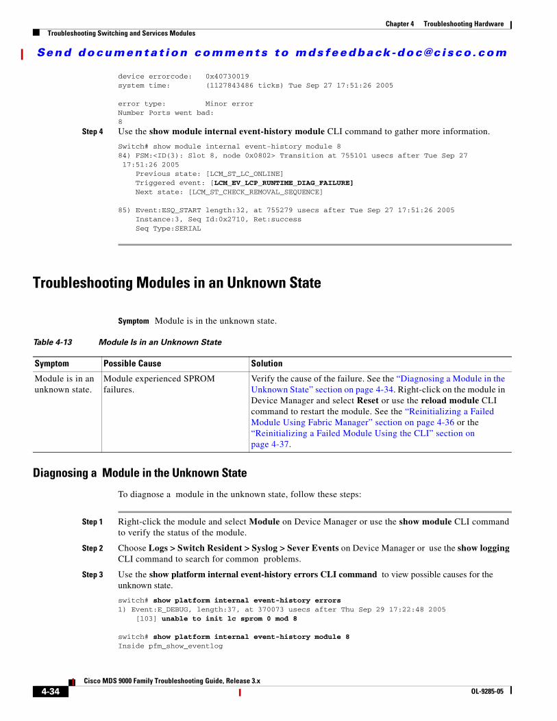
device errorcode: 0x40730019system time: (1127843486 ticks) Tue Sep 27 17:51:26 2005
error type: Minor errorNumber Ports went bad:8
Step 4 Use the show module internal event-history module CLI command to gather more information.
Switch# show module internal event-history module 884) FSM:<ID(3): Slot 8, node 0x0802> Transition at 755101 usecs after Tue Sep 27 17:51:26 2005 Previous state: [LCM_ST_LC_ONLINE] Triggered event: [LCM_EV_LCP_RUNTIME_DIAG_FAILURE] Next state: [LCM_ST_CHECK_REMOVAL_SEQUENCE]
85) Event:ESQ_START length:32, at 755279 usecs after Tue Sep 27 17:51:26 2005 Instance:3, Seq Id:0x2710, Ret:success Seq Type:SERIAL
Troubleshooting Modules in an Unknown State
Symptom Module is in the unknown state.
Diagnosing a Module in the Unknown State
To diagnose a module in the unknown state, follow these steps:
Step 1 Right-click the module and select Module on Device Manager or use the show module CLI command to verify the status of the module.
Step 2 Choose Logs > Switch Resident > Syslog > Sever Events on Device Manager or use the show logging CLI command to search for common problems.
Step 3 Use the show platform internal event-history errors CLI command to view possible causes for the unknown state.
switch# show platform internal event-history errors 1) Event:E_DEBUG, length:37, at 370073 usecs after Thu Sep 29 17:22:48 2005 [103] unable to init lc sprom 0 mod 8
switch# show platform internal event-history module 8Inside pfm_show_eventlog
Table 4-13 Module Is in an Unknown State
Symptom Possible Cause Solution
Module is in an unknown state.
Module experienced SPROM failures.
Verify the cause of the failure. See the “Diagnosing a Module in the Unknown State” section on page 4-34. Right-click on the module in Device Manager and select Reset or use the reload module CLI command to restart the module. See the “Reinitializing a Failed Module Using Fabric Manager” section on page 4-36 or the “Reinitializing a Failed Module Using the CLI” section on page 4-37.
4-34Cisco MDS 9000 Family Troubleshooting Guide, Release 3.x
OL-9285-05
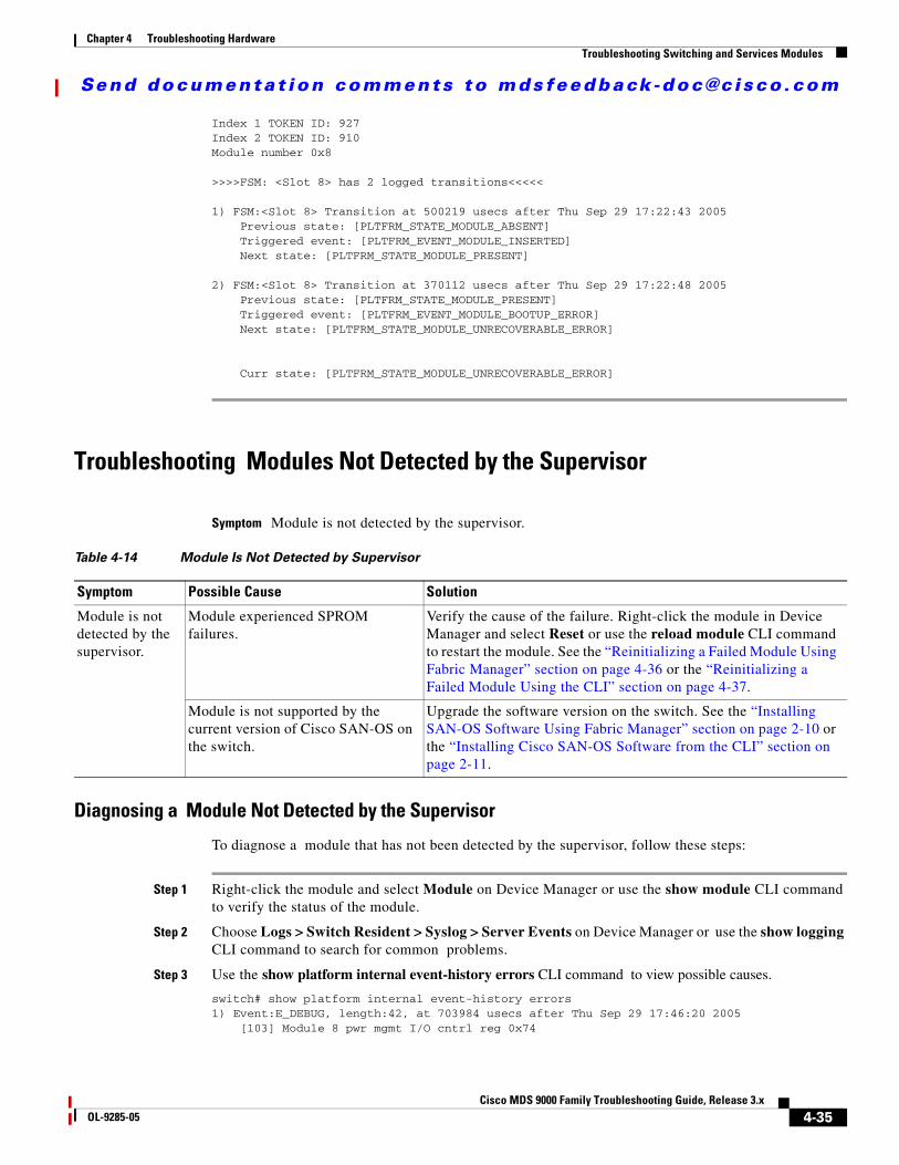
Send documenta t ion comments to mdsfeedback -doc@c i sco .com
Chapter 4 Troubleshooting HardwareTroubleshooting Switching and Services Modules
Index 1 TOKEN ID: 927 Index 2 TOKEN ID: 910Module number 0x8 >>>>FSM: <Slot 8> has 2 logged transitions<<<<<
1) FSM:<Slot 8> Transition at 500219 usecs after Thu Sep 29 17:22:43 2005 Previous state: [PLTFRM_STATE_MODULE_ABSENT] Triggered event: [PLTFRM_EVENT_MODULE_INSERTED] Next state: [PLTFRM_STATE_MODULE_PRESENT]
2) FSM:<Slot 8> Transition at 370112 usecs after Thu Sep 29 17:22:48 2005 Previous state: [PLTFRM_STATE_MODULE_PRESENT] Triggered event: [PLTFRM_EVENT_MODULE_BOOTUP_ERROR] Next state: [PLTFRM_STATE_MODULE_UNRECOVERABLE_ERROR]
Curr state: [PLTFRM_STATE_MODULE_UNRECOVERABLE_ERROR]
Troubleshooting Modules Not Detected by the Supervisor
Symptom Module is not detected by the supervisor.
Diagnosing a Module Not Detected by the Supervisor
To diagnose a module that has not been detected by the supervisor, follow these steps:
Step 1 Right-click the module and select Module on Device Manager or use the show module CLI command to verify the status of the module.
Step 2 Choose Logs > Switch Resident > Syslog > Server Events on Device Manager or use the show logging CLI command to search for common problems.
Step 3 Use the show platform internal event-history errors CLI command to view possible causes.
switch# show platform internal event-history errors1) Event:E_DEBUG, length:42, at 703984 usecs after Thu Sep 29 17:46:20 2005 [103] Module 8 pwr mgmt I/O cntrl reg 0x74
Table 4-14 Module Is Not Detected by Supervisor
Symptom Possible Cause Solution
Module is not detected by the supervisor.
Module experienced SPROM failures.
Verify the cause of the failure. Right-click the module in Device Manager and select Reset or use the reload module CLI command to restart the module. See the “Reinitializing a Failed Module Using Fabric Manager” section on page 4-36 or the “Reinitializing a Failed Module Using the CLI” section on page 4-37.
Module is not supported by the current version of Cisco SAN-OS on the switch.
Upgrade the software version on the switch. See the “Installing SAN-OS Software Using Fabric Manager” section on page 2-10 or the “Installing Cisco SAN-OS Software from the CLI” section on page 2-11.
4-35Cisco MDS 9000 Family Troubleshooting Guide, Release 3.x
OL-9285-05

Send documenta t ion comments to mdsfeedback -doc@c i sco .com
Chapter 4 Troubleshooting HardwareTroubleshooting Switching and Services Modules
2) Event:E_DEBUG, length:69, at 703888 usecs after Thu Sep 29 17:46:20 2005 [103] Module 8 pwr mgmt rev reg 0x74 brd present but power ok not set
switch# show platform internal event-history module 8Inside pfm_show_eventlogIndex 1 TOKEN ID: 927Index 2 TOKEN ID: 910Module number 0x8
>>>>FSM: <Slot 8> has 10 logged transitions<<<<<
1) FSM:<Slot 8> Transition at 370299 usecs after Thu Sep 29 17:46:12 2005 Previous state: [PLTFRM_STATE_MODULE_ABSENT] Triggered event: [PLTFRM_EVENT_MODULE_INSERTED] Next state: [PLTFRM_STATE_MODULE_PRESENT]
2) FSM:<Slot 8> Transition at 698894 usecs after Thu Sep 29 17:46:17 2005 Previous state: [PLTFRM_STATE_MODULE_PRESENT] Triggered event: [PLTFRM_EVENT_MODULE_SPROM_READ] Next state: [PLTFRM_STATE_MODULE_POWER_EVAL]
3) FSM:<Slot 8> Transition at 705551 usecs after Thu Sep 29 17:46:17 2005 Previous state: [PLTFRM_STATE_MODULE_POWER_EVAL] Triggered event: [PLTFRM_EVENT_MOD_START_POWER_UP] Next state: [PLTFRM_STATE_MODULE_START_POWER_UP]
4) FSM:<Slot 8> Transition at 110120 usecs after Thu Sep 29 17:46:20 2005 Previous state: [PLTFRM_STATE_MODULE_START_POWER_UP] Triggered event: [PLTFRM_EVENT_MOD_END_POWER_UP] Next state: [PLTFRM_STATE_MODULE_POWERED_UP]
5) FSM:<Slot 8> Transition at 704067 usecs after Thu Sep 29 17:46:20 2005 Previous state: [PLTFRM_STATE_MODULE_POWERED_UP] Triggered event: [PLTFRM_EVENT_MODULE_REMOVED] Next state: [PLTFRM_STATE_MODULE_ABSENT]
When a module is inserted into the switch, the supervisor module reads the SPROM contents of the module. If the module is supported by the current version of Cisco SAN-OS, the module will be powered-up by the supervisor module. If the power status does not show that the module has powered up properly, the module information is not relayed to the supervisor.
Reinitializing a Failed Module Using Fabric ManagerTo reinitialize a failed module using the Fabric Manager, follow these steps:
Step 1 Choose Switches > Copy Configuration to save the running configuration to the startup configuration.
Step 2 Choose Switches > Hardware. Then select the Module Status tab in the Information pane and check the Reset check box to reload the module. Click the Apply Changes icon.
Step 3 If the module is not up, choose Switches > Hardware and check the S/W Rev column to verify the software image on the module.
Step 4 If the software image on the module is not the latest, choose Tools > Other > Software Install to download the latest image to supervisor bootflash memory.
Step 5 Use the CLI to force-download the software image from the supervisor to the module.
4-36Cisco MDS 9000 Family Troubleshooting Guide, Release 3.x
OL-9285-05

Send documenta t ion comments to mdsfeedback -doc@c i sco .com
Chapter 4 Troubleshooting HardwareTroubleshooting Switching and Services Modules
switch# reload module 2 force-dnld
Step 6 If the module is still not up, choose Switches > Hardware and view the Power Admin column to verify the power status for the module.
Step 7 If the module is not powered on, remove and reseat the module and select on from the Power Admin drop-down menu to power on the module.
Step 8 If the module is still not operating, right-click on the switch in the map pane and select Reset to reload the entire switch.
Reinitializing a Failed Module Using the CLITo reinitialize a failed module using the CLI, follow these steps:
Step 1 Save the running configuration to the startup configuration.
switch# copy running-config start-config
Step 2 Reload the module.
switch# reload module 2
Step 3 If the module is not operating, verify the software image on the module.
switch# show module
Step 4 If the software image on the module is not the latest, download the latest image to supervisor bootflash memory.
switch# copy tftp: bootflash:
Step 5 Force-download the software image from the supervisor to the module.
switch# reload module 2 force-dnld
Step 6 If the module is still not operating, verify the power status for the module.
switch# show environment power
Step 7 If the module is not powered on, remove and reseat the module and then power on the module.
switch# config tswitch(config)# no poweroff module 2switch(config)# exitswitch#
Step 8 If the module is still not operating, reload the entire switch.
switch# reload
4-37Cisco MDS 9000 Family Troubleshooting Guide, Release 3.x
OL-9285-05

Send documenta t ion comments to mdsfeedback -doc@c i sco .com
Chapter 4 Troubleshooting HardwareTroubleshooting Switching and Services Modules
Module ResetsResets and reboots of modules are covered in detail in the “Troubleshooting Cisco SAN-OS Software System Reboots” section on page 2-13. If you use the module reset-reason CLI command and the output has an “unknown” reset reason, this may indicate a hardware problem. Some of the conditions that may cause this include the following:
• The switch experienced a power reset. This may be because you reset the power supplies or because of a power interruption or failure.
• The front panel reset button on the supervisor module was pressed.
• Any hardware failure that caused the processor, dynamic memory, or I/O to reset or hang.
4-38Cisco MDS 9000 Family Troubleshooting Guide, Release 3.x
OL-9285-05