trusted communications interface give helpful information about using or setting up the equipment....
TRANSCRIPT

PD-T8151B Trusted
Rockwell Automation Publication PD-T8151B Issue 25
Trusted Communications Interface
Product Overview
The Trusted® Communications Interface (CI) is an intelligent module that provides a range of communication services for the Trusted Controller, minimising communication loading of the Triple Modular Redundant (TMR) Processor.
A user-configurable module, the CI can support multiple communication media.
Up to four Communications Interfaces (CIs) can be supported by a Trusted System.
Features:
• Trusted Operating System.
• Dual Ethernet and four serial ports.
• Support for a wide range of communication protocols.
• Secure, dependable communications via high performance communications links.
• Modbus Slave.
• Optional Modbus Master (with T812X Trusted Processor Interface Adapter).
• Optional Sequence Of Events (SOE) Over Modbus.
• Front Panel serial diagnostic port, fault and status indicators.
Note: This product description refers to modules with firmware version 352020 build 3 onwards and firmware version 353570 only. For firmware versions up to 2.04 refer to the Issue 6 version of this document.

Trusted PD-T8151B
Rockwell Automation Publication PD-T8151B Issue 25
Page intentionally left blank

Trusted Communications Interface PREFACE
Rockwell Automation Publication PD-T8151B Issue 25 i
PREFACE
In no event will Rockwell Automation be responsible or liable for indirect or consequential damages resulting from the use or application of this equipment. The examples given in this manual are included solely for illustrative purposes. Because of the many variables and requirements related to any particular installation, Rockwell Automation does not assume responsibility or reliability for actual use based on the examples and diagrams.
No patent liability is assumed by Rockwell Automation, with respect to use of information, circuits, equipment, or software described in this manual.
All trademarks are acknowledged.
DISCLAIMER
It is not intended that the information in this publication covers every possible detail about the construction, operation, or maintenance of a control system installation. You should also refer to your own local (or supplied) system safety manual, installation and operator/maintenance manuals.
REVISION AND UPDATING POLICY
This document is based on information available at the time of its publication. The document contents are subject to change from time to time. The latest versions of the manuals are available at the Rockwell Automation Literature Library under "Product Information" information "Critical Process Control & Safety Systems".
TRUSTED RELEASE
This technical manual applies to Trusted Release: 3.6.1.
LATEST PRODUCT INFORMATION
For the latest information about this product review the Product Notifications and Technical Notes issued by technical support. Product Notifications and product support are available at the Rockwell Automation Support Centre at http://rockwellautomation.custhelp.com
At the Search Knowledgebase tab select the option "By Product" then scroll down and select the Trusted product.
Some of the Answer ID’s in the Knowledge Base require a TechConnect Support Contract. For more information about TechConnect Support Contract Access Level and Features please click on the following link:
https://rockwellautomation.custhelp.com/app/answers/detail/a_id/50871
This will get you to the login page where you must enter your login details.

PREFACE Trusted Communications Interface
ii Issue 25 Rockwell Automation Publication PD-T8151B
IMPORTANT A login is required to access the link. If you do not have an account then you can create one using the "Sign Up" link at the top right of the web page.
DOCUMENTATION FEEDBACK
Your comments help us to write better user documentation. If you discover an error, or have a suggestion on how to make this publication better, send your comment to our technical support group at http://rockwellautomation.custhelp.com

Trusted Communications Interface PREFACE
Rockwell Automation Publication PD-T8151B Issue 25 iii
SCOPE
This manual specifies the maintenance requirements and describes the procedures to assist troubleshooting and maintenance of a Trusted system.
WHO SHOULD USE THIS MANUAL
This manual is for plant maintenance personnel who are experienced in the operation and maintenance of electronic equipment and are trained to work with safety systems.
SYMBOLS
In this manual we will use these notices to tell you about safety considerations.
SHOCK HAZARD: Identifies an electrical shock hazard. If a warning label is fitted, it can be on or inside the equipment.
WARNING: Identifies information about practices or circumstances that can cause an explosion in a hazardous environment, which can cause injury or death, property damage or economic loss.
ATTENTION: Identifies information about practices or circumstances that can cause injury or death.
CAUTION: Identifies information about practices or circumstances that can cause property damage or economic loss.
BURN HAZARD: Identifies where a surface can reach dangerous temperatures. If a warning label is fitted, it can be on or inside the equipment.
This symbol identifies items which must be thought about and put in place when designing and assembling a Trusted controller for use in a Safety Instrumented Function (SIF). It appears extensively in the Trusted Safety Manual.
IMPORTANT Identifies information that is critical for successful application and understanding of the product.
NOTE Provides key information about the product or service.
TIP Tips give helpful information about using or setting up the equipment.
PREFACE Trusted Communications Interface
iv Issue 25 Rockwell Automation Publication PD-T8151B
WARNINGS AND CAUTIONS
WARNING: EXPLOSION RISK
Do not connect or disconnect equipment while the circuit is live or unless the area is known to be free of ignitable concentrations or equivalent
AVERTISSEMENT - RISQUE D’EXPLOSION
Ne pas connecter ou déconnecter l’équipement alors qu’il est sous tension, sauf si l’environnement est exempt de concentrations inflammables ou équivalente
MAINTENANCE
Maintenance must be carried out only by qualified personnel. Failure to follow these instructions may result in personal injury.
CAUTION: RADIO FREQUENCY INTERFERENCE
Most electronic equipment is influenced by Radio Frequency Interference. Caution should be exercised with regard to the use of portable communications equipment around such equipment. Signs should be posted in the vicinity of the equipment cautioning against the use of portable communications equipment.
CAUTION:
The module PCBs contains static sensitive components. Static handling precautions must be observed. DO NOT touch exposed connector pins or attempt to dismantle a module.

Trusted Communications Interface PREFACE
Rockwell Automation Publication PD-T8151B Issue 25 v
ISSUE RECORD
Issue Date Comments
12 Added Modicon open Modbus TCP on port 502. This was released in build 20 as part of release 3.4
13 Added 8151B hardware rev C changes. This hardware revision removes 10 Base 2
14 Jan 05 TQ 780, 1114, formatting
15 Sept 05 MR000100-11 Modbus Master Enhancements
16 Sep 05 Format
17 Aug 06 Polarising
18 Nov 06 Specifications
19 Mar 07 Read/Write Scheduling
20 Nov 07 Reorganised
21 Apr 10 Reference to T8173 Gateway Adapter
22 Sep 15 Rebranded and reformatted
23 Apr 16 Correction of typographical errors and updated to incorporate IEEE standards.
24 Apr 16 Standardisation of Relative Humidity and Operating Temperature Statements in Specifications Section
25 Apr 18 Ethernet LED behaviour revised to reflect latest hardware revision. New look front panel. Reformatted and updated Specifications table.

PREFACE Trusted Communications Interface
vi Issue 25 Rockwell Automation Publication PD-T8151B
Page intentionally left blank

Trusted Communications Interface Table of Contents
Rockwell Automation Publication PD-T8151B Issue 25 1
Table of Contents
1. Description ............................................................................................................ 5
1.1. Module Versions ........................................................................................................................ 5 1.2. Associated Equipment and Software ......................................................................................... 5 1.3. Overview .................................................................................................................................... 6
1.3.1. Hardware ............................................................................................................................ 6 1.3.2. Communications ................................................................................................................. 7
2. Installation ............................................................................................................ 9
2.1. Module Insertion/Removal ........................................................................................................ 9 2.2. PCBs and Connectors ............................................................................................................... 10
2.2.1. External I/O Connector ..................................................................................................... 10 2.3. Module Pin-out Connections ................................................................................................... 10 2.4. Trusted Module Polarisation/Keying. ...................................................................................... 12
3. Application .......................................................................................................... 13
3.1. Supported Protocols ................................................................................................................ 13 3.1.1. Front Panel Serial Port ...................................................................................................... 13 3.1.2. Rear Serial Ports ............................................................................................................... 13 3.1.3. Ethernet Ports .................................................................................................................. 13
3.2. System.INI file .......................................................................................................................... 14 3.3. Main Screen Parameters .......................................................................................................... 14
3.3.1. Ethernet Port Settings TCP/IP 0 and TCP/IP 1 .................................................................. 15 3.3.2. Default Gateway ............................................................................................................... 16 3.3.3. Multicast ........................................................................................................................... 16 3.3.4. Serial Ports ........................................................................................................................ 17
3.4. Modbus Slave ........................................................................................................................... 18 3.4.1. Connection Timeout ......................................................................................................... 19 3.4.2. SOE over Modbus ............................................................................................................. 19 3.4.3. SOE over Modbus: Requirements .................................................................................... 20 3.4.4. SOE over Modbus: Redundant Configurations ................................................................. 21
3.5. Modbus Master ........................................................................................................................ 22 3.5.1. Modbus Master Configuration ......................................................................................... 23 3.5.2. Configuration Tab ............................................................................................................. 23 3.5.3. Broadcast Tab ................................................................................................................... 25 3.5.4. Statistics Tab ..................................................................................................................... 28 3.5.5. Modbus Slave Configuration ............................................................................................ 30 3.5.6. Configuration Tab ............................................................................................................. 31 3.5.7. Messages Tab ................................................................................................................... 33 3.5.8. Statistics Tab ..................................................................................................................... 35 3.5.9. Validation Tool.................................................................................................................. 38
3.6. Modbus Master Polling Sequence ........................................................................................... 39 3.7. Modbus Master Redundant Configurations ............................................................................ 41

Table of Contents Trusted Communications Interface
2 Issue 25 Rockwell Automation Publication PD-T8151B
3.8. Modbus Compatibility .............................................................................................................. 41 3.8.1. Modbus Write Protection Compatibility .......................................................................... 42
3.9. Modbus Master Timing and Throughput Rules ....................................................................... 42 3.10. Modbus Slave Timing and Throughput Rules .......................................................................... 44 3.11. I/O Complex Equipment Definition ‘TCI’ .................................................................................. 45
4. Operation ............................................................................................................ 47
4.1. Front Panel ............................................................................................................................... 47 4.2. Module Status LEDs.................................................................................................................. 48
5. Fault Finding and Maintenance ............................................................................. 51
5.1. Fault Reporting ......................................................................................................................... 51 5.2. Module Faults .......................................................................................................................... 51 5.3. Module Replacement ............................................................................................................... 51 5.4. Command Line Diagnostics ...................................................................................................... 51
5.4.1. Top Level Commands ....................................................................................................... 52 5.4.2. Task Commands................................................................................................................ 52 5.4.3. Hierarchical Prompts ........................................................................................................ 54 5.4.4. Trace Diagnostics .............................................................................................................. 54
6. Communications Wiring........................................................................................ 57
6.1. RS232 Communications Standard ............................................................................................ 57 6.1.1. Maximum Cable Length .................................................................................................... 60
6.2. RS485 Communications Standard ............................................................................................ 60 6.2.1. RS485 Full Duplex ............................................................................................................. 60 6.2.2. RS485 Full Duplex Multiplexed ......................................................................................... 61 6.2.3. RS485 Half Duplex Multiplexed ........................................................................................ 61 6.2.4. Signal Ground ................................................................................................................... 62 6.2.5. A and B Circuit Designators .............................................................................................. 62 6.2.6. Maximum Cable Length .................................................................................................... 63 6.2.7. RS485 Connections ........................................................................................................... 63
6.3. Ethernet – 10Base2 .................................................................................................................. 64 6.4. Ethernet – 10BaseT/100BaseT ................................................................................................. 65
6.4.1. General Notes ................................................................................................................... 66 6.4.2. Network Reflections ......................................................................................................... 67 6.4.3. Network Load ................................................................................................................... 67
6.5. Interface Adapter Connectors .................................................................................................. 68 6.6. Further Sources of Information ............................................................................................... 70
7. SOE Over Modbus Protocol ..................................................................................... 72
7.1. SOE Address Window ............................................................................................................... 72 7.1.1. Data Blocks ....................................................................................................................... 75 7.1.2. Time Stamp Blocks ........................................................................................................... 75
7.2. Variable Blocks ......................................................................................................................... 77 7.3. Protocol Responsibilities .......................................................................................................... 79

Trusted Communications Interface Table of Contents
Rockwell Automation Publication PD-T8151B Issue 25 3
7.4. SOE Over Modbus Service Responsibilities .............................................................................. 79 7.5. Modbus Master Responsibilities .............................................................................................. 79 7.6. SOE_DATA Contents ................................................................................................................. 80
8. Specifications ....................................................................................................... 81

Table of Contents Trusted Communications Interface
4 Issue 25 Rockwell Automation Publication PD-T8151B
Page intentionally left blank
Trusted Communications Interface 1. Description
Rockwell Automation Publication PD-T8151B Issue 25 5
1. Description
1.1. Module Versions
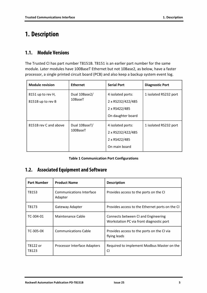
The Trusted CI has part number T8151B. T8151 is an earlier part number for the same module. Later modules have 100BaseT Ethernet but not 10Base2, as below, have a faster processor, a single printed circuit board (PCB) and also keep a backup system event log.
Module revision Ethernet Serial Port Diagnostic Port
8151 up to rev H,
8151B up to rev B
Dual 10Base2/ 10BaseT
4 isolated ports:
2 x RS232/422/485
2 x RS422/485
On daughter board
1 isolated RS232 port
8151B rev C and above Dual 10BaseT/ 100BaseT
4 isolated ports:
2 x RS232/422/485
2 x RS422/485
On main board
1 isolated RS232 port
Table 1 Communication Port Configurations
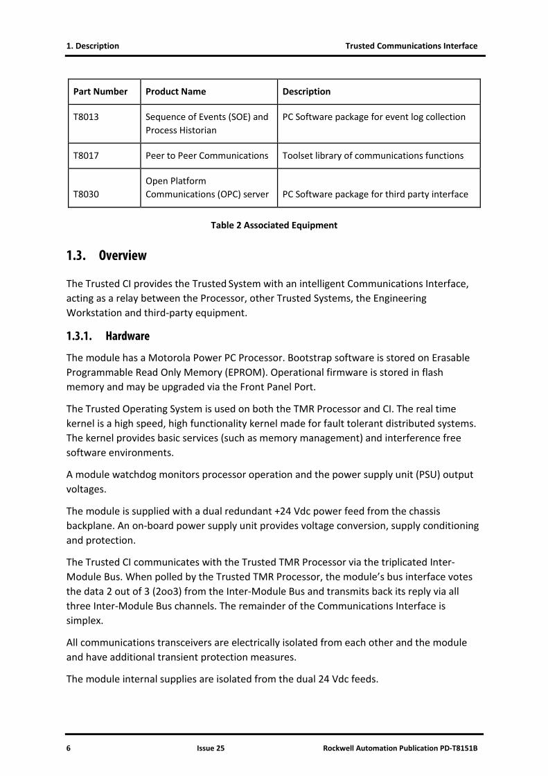
1.2. Associated Equipment and Software
Part Number Product Name Description
T8153 Communications Interface Adapter
Provides access to the ports on the CI
T8173 Gateway Adapter Provides access to the Ethernet ports on the CI
TC-304-01 Maintenance Cable Connects between CI and Engineering Workstation PC via front diagnostic port
TC-305-0X Communications Cable Provides access to the ports on the CI via flying leads
T8122 or T8123
Processor Interface Adapters Required to implement Modbus Master on the CI
1. Description Trusted Communications Interface
6 Issue 25 Rockwell Automation Publication PD-T8151B
Part Number Product Name Description
T8013 Sequence of Events (SOE) and Process Historian
PC Software package for event log collection
T8017 Peer to Peer Communications Toolset library of communications functions
T8030 Open Platform Communications (OPC) server PC Software package for third party interface
Table 2 Associated Equipment
1.3. Overview
The Trusted CI provides the Trusted System with an intelligent Communications Interface, acting as a relay between the Processor, other Trusted Systems, the Engineering Workstation and third-party equipment.
1.3.1. Hardware
The module has a Motorola Power PC Processor. Bootstrap software is stored on Erasable Programmable Read Only Memory (EPROM). Operational firmware is stored in flash memory and may be upgraded via the Front Panel Port.
The Trusted Operating System is used on both the TMR Processor and CI. The real time kernel is a high speed, high functionality kernel made for fault tolerant distributed systems. The kernel provides basic services (such as memory management) and interference free software environments.
A module watchdog monitors processor operation and the power supply unit (PSU) output voltages.
The module is supplied with a dual redundant +24 Vdc power feed from the chassis backplane. An on-board power supply unit provides voltage conversion, supply conditioning and protection.
The Trusted CI communicates with the Trusted TMR Processor via the triplicated Inter-Module Bus. When polled by the Trusted TMR Processor, the module’s bus interface votes the data 2 out of 3 (2oo3) from the Inter-Module Bus and transmits back its reply via all three Inter-Module Bus channels. The remainder of the Communications Interface is simplex.
All communications transceivers are electrically isolated from each other and the module and have additional transient protection measures.
The module internal supplies are isolated from the dual 24 Vdc feeds.

Trusted Communications Interface 1. Description
Rockwell Automation Publication PD-T8151B Issue 25 7
1.3.2. Communications
Ethernet Media Access Control (MAC) address configuration is held by the CI as part of its configuration information. Other information regarding port and protocol configuration is obtained from the TMR Processor, as part of the System.INI file.
Data is transferred between the TMR Processor and the Communications Interfaces using a common interface called the Network Variable Manager. When data is read from a Trusted System, the data is obtained from the local copy maintained on the Communications Interface, providing a fast response.
Data writes are more complicated. If a data write simply updated the local copy and was then relayed to the processor, the other Communications Interfaces in the system would carry different data. This may cause problems for redundant links.
To overcome this problem, when data is written to a Communications Interface, it is first passed to the TMR Processor and the write is acknowledged immediately by the Communications Interface (to avoid communications delays). The processor updates its own database and then sends the data back to all Communications Interfaces so that they all have the same data. This can take one or two application scans. This means that subsequent reads will receive the old data immediately after the write, until the new data has been distributed.
All changes to CI .INI parameters may be loaded online and will take immediate effect; the Communications Interface disconnects all communications and restarts. Communications is also restarted on an application online update and is shut down when the application is stopped.

1. Description Trusted Communications Interface
8 Issue 25 Rockwell Automation Publication PD-T8151B
Page intentionally left blank
Trusted Communications Interface 2. Installation
Rockwell Automation Publication PD-T8151B Issue 25 9
2. Installation
The CI can be installed in any Input / Output (I/O) slot of a controller or expander chassis, however, peer to peer communications is only supported from the processor chassis.
When installed in the chassis, the CI connects to external systems via either a CI Adapter T8153 or a TC-305-01 Communications Cable with flying leads.
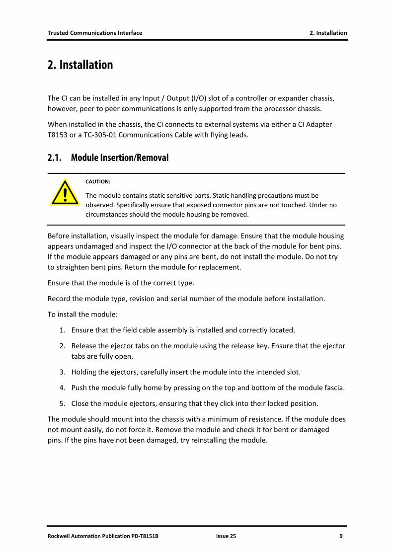
2.1. Module Insertion/Removal
CAUTION:
The module contains static sensitive parts. Static handling precautions must be observed. Specifically ensure that exposed connector pins are not touched. Under no circumstances should the module housing be removed.
Before installation, visually inspect the module for damage. Ensure that the module housing appears undamaged and inspect the I/O connector at the back of the module for bent pins. If the module appears damaged or any pins are bent, do not install the module. Do not try to straighten bent pins. Return the module for replacement.
Ensure that the module is of the correct type.
Record the module type, revision and serial number of the module before installation.
To install the module:
1. Ensure that the field cable assembly is installed and correctly located.
2. Release the ejector tabs on the module using the release key. Ensure that the ejector tabs are fully open.
3. Holding the ejectors, carefully insert the module into the intended slot.
4. Push the module fully home by pressing on the top and bottom of the module fascia.
5. Close the module ejectors, ensuring that they click into their locked position.
The module should mount into the chassis with a minimum of resistance. If the module does not mount easily, do not force it. Remove the module and check it for bent or damaged pins. If the pins have not been damaged, try reinstalling the module.

2. Installation Trusted Communications Interface
10 Issue 25 Rockwell Automation Publication PD-T8151B
2.2. PCBs and Connectors
2.2.1. External I/O Connector
This connector provides a number of discrete input and outputs. These provide the CI with the Serial and Ethernet connections. The connector is a 78+2-way DIN 41612 M-type connector. See Table 3 for connector pin-out details.
2.3. Module Pin-out Connections
Row
Pin A B C Description
1
2 50 Ω Co-ax 10Base2 Ethernet 1 (fitted on T8151 up to build H and T8151B up to build B only)
3
4 Link 1 Connector Present Link - wire to A29
5 TXD1
(RS232)
Serial Port 1
6 RTS1
(RS232) DTR1
(RS232) RXD1
(RS232)
7 CTS1
(RS232) DSR1
(RS232) DCD1
(RS232)
8 BIO1
(RS485) AIO1
(RS485) RI1 (RS232)
9 BO1 (RS485) AO1 (RS485) GND1
10
11 TXD2
(RS232) RTS2
(RS232) RXD2
(RS232) Serial Port 2
12 BIO2
(RS485) AIO2
(RS485) CTS2
(RS232)
13 BO2 (RS485) AO2 (RS485) GND2

Trusted Communications Interface 2. Installation
Rockwell Automation Publication PD-T8151B Issue 25 11
Row
Pin A B C Description
14
15 BIO3
(RS485) AIO3
(RS485) GND3 Serial Port 3
16 BO3 (RS485) AO3 (RS485) GND3
17
18 BIO4
(RS485) AIO4
(RS485) GND4 Serial Port 4
19 BO4 (RS485) AO4 (RS485) GND4
20
21 TD+1 TD-1 10/100BaseT Ethernet 1
22 RD+1 RD-1
23 EARTH1
24
25 TD+2 TD-2 10/100BaseT Ethernet 2
26 RD+2 RD-2
27 EARTH2
28
29 LINK2 Connector Present Link - wire to C4
30
31 50 Ω Co-ax 10Base2 Ethernet 2 (fitted on T8151 up to build H and T8151B up to build B only)
32
Table 3 External I/O Connector - Pin-Out

2. Installation Trusted Communications Interface
12 Issue 25 Rockwell Automation Publication PD-T8151B
2.4. Trusted Module Polarisation/Keying.
All Trusted modules have been keyed to prevent insertion into the wrong position within a chassis. The polarisation comprises two parts: the module and the associated field cable.
Each module type has been keyed during manufacture. The organisation responsible for the integration of the system must key the cable by removing the keying pieces from the cable so that they correspond with the bungs fitted to the associated module prior to fitting.
Figure 1 Module Polarisation
For Cables with Companion Slot installations both keying strips must be polarised.
For this module (T8151B) remove keying pins 1, 2 and 3.
1
12
Cable Exit
Release button
Polarising/Keying Pins.
(Remove using side cutters where identified below)
Trusted
Cable hood
Smart Swap Connector if Fitted

Trusted Communications Interface 3. Application
Rockwell Automation Publication PD-T8151B Issue 25 13
3. Application
3.1. Supported Protocols
3.1.1. Front Panel Serial Port
This port operates at 19200 baud on RS232. A command line diagnostic protocol is available via this port, accessed using a TC-304-01 Maintenance Cable and a terminal program. This protocol is not affected by the Processor Front Panel keyswitch.
3.1.2. Rear Serial Ports
These ports may be configured between 1200 and 115200 baud. All four ports support RS485, port 1 supports RS232 with full handshaking and port 2 supports RS232 without handshaking. These ports can be allocated as a Modbus Remote Terminal Unit (RTU) Slave or Master (Modbus Master requires a T8122 or T8123 Processor Interface Adapter).
3.1.3. Ethernet Ports
These ports can each support multiple protocols simultaneously.
• Modbus RTU Slave, packaged as a serial stream on Ethernet. This is appropriate for conversion to serial Modbus at terminal servers or for the Trusted OPC servers and SOE/Process Historian collector. Up to ten connections can be made to Ethernet slaves, and the port only needs to be allocated once. Port 2000 is used by default. The slave can either actively make a connection (appropriate for some terminal servers) or wait for a connection.
• Open Modbus Transport Control Protocol (TCP), an Ethernet Modbus protocol designed by Modicon. This will automatically operate if port 502 is selected. Only Modbus Slave is available on this protocol.
• Modbus RTU Master, packaged as a serial stream on Ethernet. This is enabled by fitting a T8122 or T8123 Processor Interface Adapter. The Master only makes one connection, so it may connect to one Ethernet based slave or to one chain of slaves on a serial link via a terminal server. Each CI can control up to 16 Modbus Masters, communicating with up to 64 Slaves total, with up to 400 messages total. Each Master, Slave and message can be individually controlled and monitored, including statistical data. A Modbus Master can also broadcast messages to some or all Slaves simultaneously.
• SOE over Modbus protocol. A section of the Modbus address map is used as an event buffer for SOE events (not Process Historian). This requires programming in the remote end to poll the data block (with a Modbus Master) and interpret the

3. Application Trusted Communications Interface
14 Issue 25 Rockwell Automation Publication PD-T8151B
events. This can provide a faster event transfer than the protocol used by the OPC server and SOE collector.
• Toolset communications over Ethernet. A total of two Toolset connections may be made to the system over Ethernet, one per CI (however it is advised to only connect one Toolset, see TN20011). This uses port 6000 and uses proprietary protocols. There is no need to configure this connection; it is available by default.
• Command line diagnostics protocol, as for the Front Panel serial port above. This uses port 23 and communicates with a Telnet program (e.g. Hyperterminal or Teraterm). This port is not available by default (for security), and must be enabled via a diagnostic command. Two Telnet connections may be made to the system for command line diagnostics.
• ‘Simplex’ peer to peer communications between Trusted Systems, using sxp2p definitions. This protocol uses port 4000 and is configured in the application. Refer to PD-T8017 issue 6 for configuration details. This protocol creates independent simplex data block passing networks between systems.
• ‘Enhanced’ peer to peer communications between Trusted Systems, using dxp definitions. This protocol uses port 5000 and is configured in the application. Refer to PD-T8017, latest issue for configuration details. This protocol creates multiple redundant data block passing networks between systems with transparent control, greater scope and multicasting.
• Other protocols exist for communication with legacy equipment in hybrid systems, including ICS2000 and CP2000. The ICS2000 interface and configuration are described in document 552550.
3.2. System.INI file
The system configuration tool, which is accessed via the Toolset, is a graphical interface which allows the user to represent the physical Trusted chassis and modules and then configure the system requirements in a .INI file, which is downloaded to the processor. For the CI, port configuration and some protocol parameters can be defined.
Refer to product description PD-T8082 for details of the system configuration tool.
3.3. Main Screen Parameters
The CI parameters window includes basic settings for Ethernet and serial port operation and an ‘Additional’ window for entering configuration commands not supported by the system

Trusted Communications Interface 3. Application
Rockwell Automation Publication PD-T8151B Issue 25 15
configuration tool. The window has icons to access Modbus Slave, Modbus Master and enhanced peer multicast configuration sub-windows. Each area is described below.
Figure 2 CI Configuration Screen
3.3.1. Ethernet Port Settings TCP/IP 0 and TCP/IP 1
The two Ethernet ports are listed as Transmission Control Protocol / Internet Protocol (TCP/IP) 0 and TCP/IP 1, but are described on the Front Panel as Ethernet 1 and 2. Each of the two Ethernet ports has an Internet Protocol (IP) address and a subnet mask. The subnet mask defines the portion of the whole IP address which is the network address. Devices on one network address cannot communicate to devices on other networks without a gateway.
The Ethernet port IP addresses for the two ports on a CI should be set to separate networks, i.e. the IP addresses covered by the ‘subnet mask’ should be different. If port 1 and 2 are on the same network, only one will be able to communicate.
Examples:
• Subnet mask = 255.255.255.0 in decimal

3. Application Trusted Communications Interface
16 Issue 25 Rockwell Automation Publication PD-T8151B
This equals 11111111.11111111.11111111.00000000 in binary. The 1’s in the subnet mask show where the network address portion is, i.e. any number in the first three places.
This allocates all of the first three numbers in the IP address to the network address. So IP addresses 1.2.3.123 and 1.2.3.231 are on the same network, but 1.2.4.123 is on network 1.2.4.x.
• Subnet mask = 255.255.128.0
This equals 11111111.11111111.10000000.00000000 in binary.
This allocates the first two numbers in the IP address and the highest bit of the next number to the network address. So 1.2.128.1 and 1.2.129.1 are on the same network but 1.2.127.1 is not.
3.3.2. Default Gateway
The Default Gateway is the address of a device that allows access to other networks. Since the two ports must be on different networks, only one of the ports can be on the same network as the Gateway, and so only this port can use the Gateway. The Gateway allows the port to communicate with IP addresses outside its own network, e.g. across a site Local Area Network (LAN) or even onto the internet, perhaps to allow remote diagnostics.
For example, a CI Ethernet port is connected to network 192.200.11.x (the subnet mask is 255.255.255.0). The Gateway on this network is 192.200.11.1. The CI Ethernet port is assigned an address of 192.200.11.202. This allows it to communicate to other devices on the 192.200.11.x network. In order to communicate with a device on another network, e.g. 192.200.81.145, the Default Gateway setting must match the network gateway address of 192.200.11.1. The remote device will then be able to transmit and receive packets from the CI.
3.3.3. Multicast
For Enhanced peer to peer multicast operation from release 3.5, the Multicast operation section must be configured. This is only necessary if using enhanced peer (using dxpnc40 control definitions) and data must be sent to more than one peer system with one message.

Trusted Communications Interface 3. Application
Rockwell Automation Publication PD-T8151B Issue 25 17
Click on ‘Configure Multicast’ to open the parameter window.
Figure 3 Multicast Configuration
In the window above, multicast data can be configured to be sent either from port TCP/IP 0 or TCP/IP 1 to other peers. The Maximum Hops determines the number of routers that the messages will go through before being blocked.
For each of the two Ethernet ports, configure the addresses that will be monitored for Multicast messages from other peers. One address will be sufficient to allow 64 different Multicast messages to be configured using different settings of DATA_ID. Enter an address in each port for dual redundant communications.
A Multicast peer address must be in the range 239.255.0.0 to 239.255.255.255 for a local site. This range prevents the messages from being forwarded outside the immediate network.
3.3.4. Serial Ports
The four Serial Ports may each be configured for baud rate, data bits, parity, stop bits and line type (the Front Panel Serial Port is essentially ‘port 0’ and cannot be configured).
Note: The normal pattern uses two bits after each data byte. This is either odd/even parity and one stop bit, or no parity and two stop bits.
• RS232 is only available on Serial Ports 1 and 2. The setting for this mode is ‘rs232’.

3. Application Trusted Communications Interface
18 Issue 25 Rockwell Automation Publication PD-T8151B
• rs485fd configures a four wire point-to-point connection.
• rs485hdmux configures a two wire multi-dropped connection. rs485 performs the same function.
• rs485fdmux configures a four wire multi-dropped connection.
3.4. Modbus Slave
Clicking ’Configure Modbus Slave’ opens the Slave Configuration window.
Figure 4 Modbus Slave Configuration Window

Trusted Communications Interface 3. Application
Rockwell Automation Publication PD-T8151B Issue 25 19
It is possible to configure up to 10 Modbus Slaves operating in the CI (not to be confused with the setup of remote Modbus Slaves which the CI Modbus Masters communicate with). These may be allocated to Serial or Ethernet ports.
If a Slave is required, check the box ‘Use This Slave’. Set the Slave address that the CI will respond to, usually 1 on a point to point link but in the range 1 to 127.
If the Slave will appear on a Serial port, check ‘Serial’. Choose the port to be used. A Serial port can only be used for Modbus Slave or Master but not both.
If the Slave will appear on an Ethernet port, it is packaged in Internet Protocol (IP). The IP layer must be established before Modbus data can be delivered. The CI can either set up a TCP/IP connection itself or await a call from the remote end. This connection will probably be to a terminal server, and it may require trial and error and a close look at the terminal server configuration to find whether it is expecting to set up or wait for connection. The default port used for Modbus on the CI is 2000; although this may be changed it is rarely necessary (only if port 2000 is used elsewhere). If the CI is to initiate the connection, enter the IP address of the remote end.
Port 502 is reserved for the Modicon Open TCP Modbus protocol. The Slave port should be set to 502 if this protocol is to be used. This protocol is only available as a Modbus Slave.
The settings above relate to each individual Slave. The following settings are common to the operation of Modbus Slaves.
3.4.1. Connection Timeout
‘Connection Timeout’ should be left at the default of ‘Disconnect after 300 seconds’. This allows Ethernet based Slaves to recover properly after a lost connection. 300 seconds is appropriate for communications where cable breaks are not normally expected (e.g. not involving a modem or other link likely to disconnect).
The TCP/IP stack does not detect the loss of Modbus communications caused by a pulled connection or cable break. A broken connection will not be seen by the TCP/IP stack, and will be retained as a valid connection. When the broken connection is recovered, the Modbus Master may resume communications using the existing connection, but it is more likely to establish a new connection. Each re-connection consumes one of the available connections. If this occurs on a regular basis, all the available connections will be consumed and no further connection will be possible. On early CIs that do not recognise the connection timeout setting, removing and re-inserting the CI and rebooting it will recover the available connections.
3.4.2. SOE over Modbus
The SOE over Modbus protocol allows buffered transfer of events via a CI Modbus Slave. This protocol provides access to the SOE buffer events (but not Process Historian), over a Modbus data link, for where the default OPC server/SOE collector protocols prove too slow. However, SOE over Modbus protocol requires an application in the Modbus Master (remote

3. Application Trusted Communications Interface
20 Issue 25 Rockwell Automation Publication PD-T8151B
end) to read, interact with and interpret the buffer, and assign event data to variables. For more information on events and their configuration, see product description PD-T8013.
SOE over Modbus is implemented as a service running on a CI. When enabled, the service manages a “window” of Modbus addresses that implement the protocol, which is automatically available on all ports of that module which are configured as Modbus Slaves.
The settings in the Modbus Slave Configuration window define a block of register addresses which provide a window for accessing events.
Selecting the Enable check box enables the service. Once enabled, the Base Address and Block Count fields will become active.
• Base Address Field: This field specifies that starting address of the window that the protocol will use. It can be located at any valid Modbus holding register address (i.e. Modbus addresses in the 40,000 to 49,984 range). As this field is modified, the End Address field will be updated.
• Block Count Field: This specifies the number of events that can be read by the Modbus Master in a single Modbus read. Each event block requires 4 Modbus holding register addresses. As the Block Count field is modified, the End Address field will be updated. The Event Block Count must specify at least 2 event blocks.
• End Address Field: The End Address field specifies the last address of the Modbus address “window” that the SOE Over Modbus protocol will use. It is calculated as:
o start address as specified in the Base Address field
o + 7 (for protocol overhead)
o + (the number of blocks as specified in the Block Count field * 4)
The Modbus address “window” as indicated by the Base Address and End Address fields should be reserved exclusively for use by the SOE over Modbus service. Defining a variable with a conflicting Modbus address may lead to loss of events, corrupted event data, or protocol errors that prevent the continued operation of the SOE over Modbus service.
The SOE over Modbus protocol and data block format are described in section 7 of this document.
3.4.3. SOE over Modbus: Requirements
In order to use SOE over Modbus, there are several configuration steps that must be taken.
• At least one Modbus Slave must be configured and active in order to use the SOE over Modbus service.
• Configure variables for SOE logging. Variables should have the “Enable SOE Logging” extended attribute set (or be connected to a SOE board) and have a valid Modbus address.

Trusted Communications Interface 3. Application
Rockwell Automation Publication PD-T8151B Issue 25 21
• Configure the SOE Over Modbus service. Each communication module that will support the service must be configured. Redundant configurations must be defined with the same information.
• Resolve Modbus address conflicts. The Modbus addresses specified by the Address Window must be unique, and not defined by the application except for certain addresses in redundant configurations.
• Define Modbus addresses for redundant configurations. For redundant configurations across communication modules, the first 4 addresses in the SOE Address window should be defined by the application, but not used elsewhere.
• Configure the Modbus Master. Ensure the Modbus Master is configured with the appropriate addresses, and has implemented the SOE Over Modbus protocol.
3.4.4. SOE over Modbus: Redundant Configurations
The SOE over Modbus service runs independently on each CI module on which it is configured. While the service on each module will provide the same event data, the presentation of that data to a Modbus Master is not normally synchronized. The service can be used in a redundant, fail-over configuration by taking the following steps.
• Uncheck the “Auto Protect Network Variables” checkbox. This facility must be disabled in the System.INI file as shown below for configuration of a redundant CI. The default setting is for “Auto Protect Network Variables” to be enabled.
The disabled status is necessary for the CIs to correctly maintain synchronisation between themselves when events are uploaded from one and not the other.
• Each CI module that is to be a part of the redundant configuration must be configured for SOE over Modbus using the same values for the Base Address and Block Count.
• In the Toolset, 4 integer variables must be defined in the dictionary and assigned a Modbus address that corresponds to the first 4 addresses in the SOE Address Window, starting at the address defined by the Base Address field. These variables will be used by the SOE over Modbus services on each communication module to synchronise the presentation of event data.

3. Application Trusted Communications Interface
22 Issue 25 Rockwell Automation Publication PD-T8151B
3.5. Modbus Master
The Trusted CI may also act as a Modbus Master with the addition of the Processor Interface Adapter T8122 or T8123. See Product Description PD-T812X for details.
On a system without the appropriate Processor Interface Adapter connected, the Modbus Master may be configured and downloaded into the Trusted System. However, no communications activity will take place once the system is running.
Modbus Master operates on the CI. It is capable of linking to a wide range of external devices using either Serial or Ethernet links, supporting the Modbus RTU protocol (Modicon Open Modbus TCP is not supported).
Clicking ’Configure Modbus Master’ opens the Master configuration window.
Figure 5 Modbus Master Configuration Window
The Modbus Master configuration is hierarchical. The first step is to configure a Master, then to configure the Slaves serving that Master, then configure the messages carrying data to and from each Slave.

Trusted Communications Interface 3. Application
Rockwell Automation Publication PD-T8151B Issue 25 23
3.5.1. Modbus Master Configuration
Create a new Modbus Master by clicking ‘+ Add Master’. This enables the controls to remove the Master, add a Slave responding to that Master, and to remove a Slave. The three configuration tabs (Configuration, Broadcast and Statistics) are now available for the new Master. The Master name can be changed by double clicking on the name or clicking on ‘Change Name’. ‘Save’ stores changes made so far, and ‘Undo’ loads the last saved state. ‘Validate’ will check the settings for any obvious errors and omissions (but will not guarantee it will work).
Figure 6 Modbus Master Configuration
3.5.2. Configuration Tab
The Configuration tab for a Modbus Master includes the communications settings and controls for the Master.
• Communications Link: This defines the physical communications link that will be used for this Modbus Master device. Select Ethernet or Serial. For Ethernet, enter the IP address of the CI port to be used, and the TCP/IP port number (1000 by default). For Serial, choose the port to be used. The actual Serial parameters are as defined in the Communications Interface configuration screen.
3. Application Trusted Communications Interface
24 Issue 25 Rockwell Automation Publication PD-T8151B
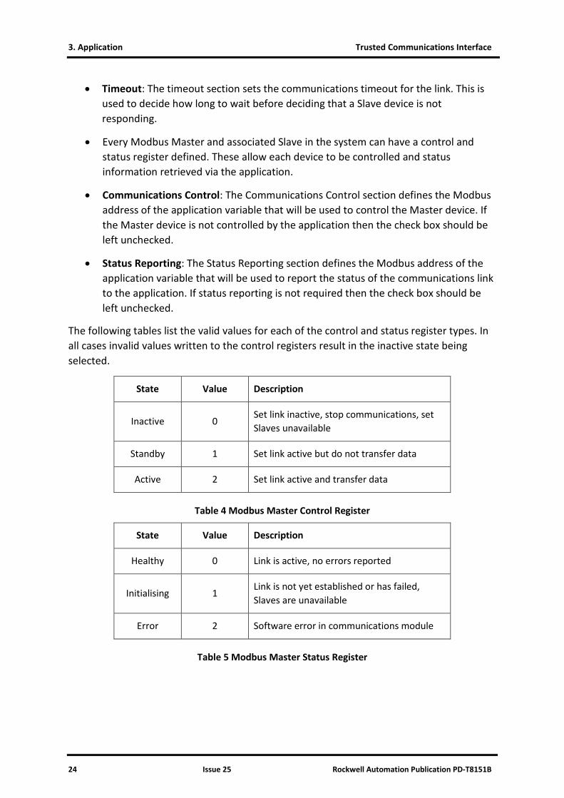
• Timeout: The timeout section sets the communications timeout for the link. This is used to decide how long to wait before deciding that a Slave device is not responding.
• Every Modbus Master and associated Slave in the system can have a control and status register defined. These allow each device to be controlled and status information retrieved via the application.
• Communications Control: The Communications Control section defines the Modbus address of the application variable that will be used to control the Master device. If the Master device is not controlled by the application then the check box should be left unchecked.
• Status Reporting: The Status Reporting section defines the Modbus address of the application variable that will be used to report the status of the communications link to the application. If status reporting is not required then the check box should be left unchecked.
The following tables list the valid values for each of the control and status register types. In all cases invalid values written to the control registers result in the inactive state being selected.
State Value Description
Inactive 0 Set link inactive, stop communications, set Slaves unavailable
Standby 1 Set link active but do not transfer data
Active 2 Set link active and transfer data
Table 4 Modbus Master Control Register
State Value Description
Healthy 0 Link is active, no errors reported
Initialising 1 Link is not yet established or has failed, Slaves are unavailable
Error 2 Software error in communications module
Table 5 Modbus Master Status Register

Trusted Communications Interface 3. Application
Rockwell Automation Publication PD-T8151B Issue 25 25
3.5.3. Broadcast Tab
Figure 7 Modbus Master Broadcast Configuration
The Modbus broadcast mode is supported by the Modbus Master. The Modbus broadcast is an unacknowledged write data message sent from the Master using Slave ID 0. All Slaves on the communications link that support broadcast messages will process the message. As the data transfer is one way only, broadcast messages are restricted to coil and holding register writes only. A broadcast sequence can consist of any number of messages, each of which may be individually enabled or disabled from the application. Each broadcast message counts towards the maximum number of Slave messages allowed for the CI.
Note: When using broadcast messages, at least one non-broadcast message addressed to a specific Slave must be configured.
Broadcast mode can be individually enabled for any Master device. Select ‘Use Broadcast Mode’ to enable broadcast messages.
If message control is required (see the modes of operation below), select ‘Use Control Variable’ and enter the Modbus address of an application variable that will be used to control the message. Where a control register is defined for either a broadcast or Slave message, the message is enabled when the register contains a zero value. All other values will result in the message being disabled. The data type used for control variable can be either Boolean or integer but not real.

3. Application Trusted Communications Interface
26 Issue 25 Rockwell Automation Publication PD-T8151B
Variable Data Type Value Message
Boolean False Enabled
True Disabled
Integer 0 Enabled
Non-zero Disabled
Table 6 Modbus Message Control Values
There are three modes of operation.
• One Shot: In this mode a single broadcast sequence is sent when an edge is detected on the control variable within the application. Once all enabled broadcast messages have been sent, the mode will be suspended until a new edge is seen on the control variable.
• Message Count: The broadcast sequence is sent after a fixed number of Slave messages have been sent. The number of messages is set in the configuration (‘Every xxx messages’) and cannot be changed by the application at run time. All messages sent to the Slaves are counted. Note that messages which have been configured but are disabled by the application will not be counted as sent messages. Once the required number of Slave messages has been sent, the broadcast sequence will commence. The control variable may be configured to enable and disable the broadcast mode if required.
• Fixed Time: The broadcast sequence is sent at a fixed time interval defined in the configuration. The time interval is set in the configuration (‘Every xxx msec’) and cannot be changed by the application at run time. The time interval measurement is taken from the point of sending the first broadcast message and ignores the time taken to send the sequence and any wait times. Therefore the time interval must be set to a value greater than the time taken to send the broadcast sequence. The control variable may be configured to enable and disable the broadcast mode if required.
When a broadcast is initiated, all enabled messages in the list are sent one after another. The time interval between each message can be configured to allow for the processing time of the Slave devices (using ‘Wait Time’).
The Slave message scheduling can be configured using ‘Slave List Control’ to restart with the first defined message for each Slave after the broadcast sequence has completed (‘Restart’), or suspend the sequence and continue at the same point after the broadcast (‘Suspend’).

Trusted Communications Interface 3. Application
Rockwell Automation Publication PD-T8151B Issue 25 27
To create a broadcast message, click ‘New’.
Figure 8 Broadcast Message Configuration
The Message Configuration window is the same as that used for messages to specific Slaves.
Select a Message Type from the list. For broadcast messages, only Write Coils (multiple Boolean variables) and Write Registers (multiple analogue variables) messages are allowed.
The Variable Network Address is the Modbus address range of the variables as mapped in the Trusted System. Only the starting address is needed; the end address is calculated automatically.
The Modbus Slave Address is the Slave’s address range for the variables. Enter the start and end addresses. Coils are addressed from 1 to 9999 and registers are mapped from 40001 to 49999. Up to 512 coils or 123 registers may be written in a single message.
If message control is required, select ‘Application Controls Message’ and enter the Modbus address of an application variable that will be used to control the message. Where a control register is defined for either a broadcast or Slave message, the message is enabled when the register contains a zero value. All other values will result in the message being disabled. The data type used for control variable can be either Boolean or integer but not real.
Variable Data Type Value Message
Boolean False Enabled
True Disabled
Integer 0 Enabled
Non-zero Disabled
Table 7 Modbus Message Control Values
3. Application Trusted Communications Interface
28 Issue 25 Rockwell Automation Publication PD-T8151B
3.5.4. Statistics Tab
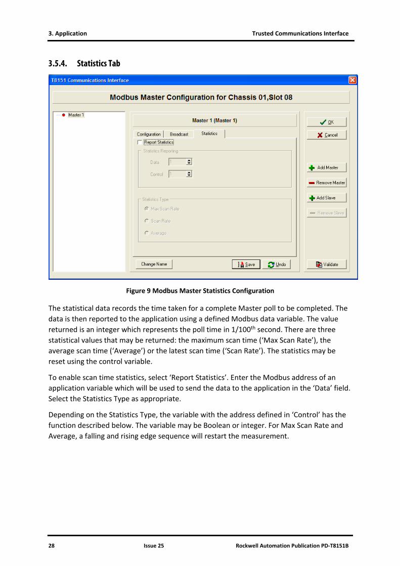
Figure 9 Modbus Master Statistics Configuration
The statistical data records the time taken for a complete Master poll to be completed. The data is then reported to the application using a defined Modbus data variable. The value returned is an integer which represents the poll time in 1/100th second. There are three statistical values that may be returned: the maximum scan time (‘Max Scan Rate’), the average scan time (‘Average’) or the latest scan time (‘Scan Rate’). The statistics may be reset using the control variable.
To enable scan time statistics, select ‘Report Statistics’. Enter the Modbus address of an application variable which will be used to send the data to the application in the ‘Data’ field. Select the Statistics Type as appropriate.
Depending on the Statistics Type, the variable with the address defined in ‘Control’ has the function described below. The variable may be Boolean or integer. For Max Scan Rate and Average, a falling and rising edge sequence will restart the measurement.

Trusted Communications Interface 3. Application
Rockwell Automation Publication PD-T8151B Issue 25 29
Statistics Mode Control Variable Value Result
Max Scan Rate
False → True (Boolean)
0 → non-zero (Integer)
Max value will remain until next cycle completed.
Max value then updated with time of next complete cycle.
True → False (Boolean)
non-zero → 0 (Integer) Triggers a reset.
Scan Rate
False → True (Boolean)
0 → non-zero (Integer) No effect (data updated every cycle).
True → False (Boolean)
non-zero → 0 (Integer) No effect (data updated every cycle).
Average
False → True (Boolean)
0 → non-zero (Integer)
Average value will remain until next cycle completed.
Average value then updated with time of next complete cycle.
True → False (Boolean)
non-zero → 0 (Integer) Triggers a reset.
Table 8 Modbus Statistics Control
3. Application Trusted Communications Interface
30 Issue 25 Rockwell Automation Publication PD-T8151B
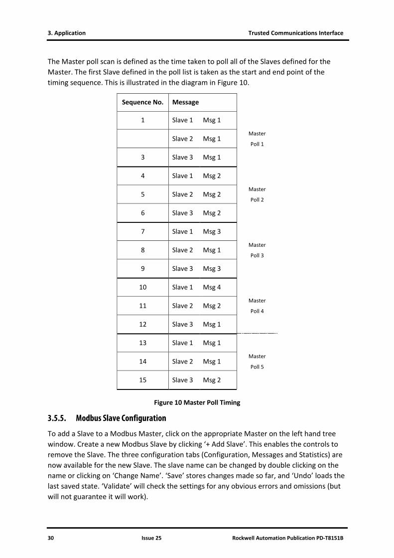
The Master poll scan is defined as the time taken to poll all of the Slaves defined for the Master. The first Slave defined in the poll list is taken as the start and end point of the timing sequence. This is illustrated in the diagram in Figure 10.
Sequence No. Message
1 Slave 1 Msg 1
Master
Poll 1 Slave 2 Msg 1
3 Slave 3 Msg 1
4 Slave 1 Msg 2
Master
Poll 2 5 Slave 2 Msg 2
6 Slave 3 Msg 2
7 Slave 1 Msg 3
Master
Poll 3 8 Slave 2 Msg 1
9 Slave 3 Msg 3
10 Slave 1 Msg 4
Master
Poll 4 11 Slave 2 Msg 2
12 Slave 3 Msg 1
13 Slave 1 Msg 1
Master
Poll 5 14 Slave 2 Msg 1
15 Slave 3 Msg 2
Figure 10 Master Poll Timing
3.5.5. Modbus Slave Configuration
To add a Slave to a Modbus Master, click on the appropriate Master on the left hand tree window. Create a new Modbus Slave by clicking ‘+ Add Slave’. This enables the controls to remove the Slave. The three configuration tabs (Configuration, Messages and Statistics) are now available for the new Slave. The slave name can be changed by double clicking on the name or clicking on ‘Change Name’. ‘Save’ stores changes made so far, and ‘Undo’ loads the last saved state. ‘Validate’ will check the settings for any obvious errors and omissions (but will not guarantee it will work).
Trusted Communications Interface 3. Application
Rockwell Automation Publication PD-T8151B Issue 25 31
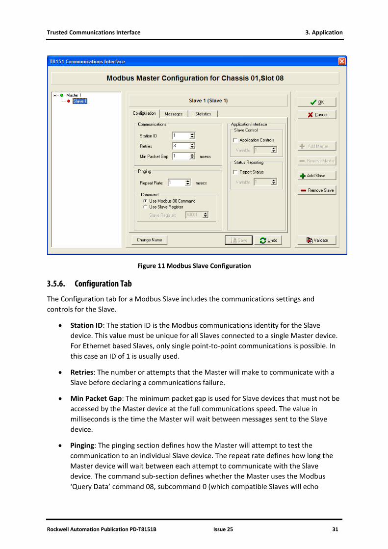
Figure 11 Modbus Slave Configuration
3.5.6. Configuration Tab
The Configuration tab for a Modbus Slave includes the communications settings and controls for the Slave.
• Station ID: The station ID is the Modbus communications identity for the Slave device. This value must be unique for all Slaves connected to a single Master device. For Ethernet based Slaves, only single point-to-point communications is possible. In this case an ID of 1 is usually used.
• Retries: The number or attempts that the Master will make to communicate with a Slave before declaring a communications failure.
• Min Packet Gap: The minimum packet gap is used for Slave devices that must not be accessed by the Master device at the full communications speed. The value in milliseconds is the time the Master will wait between messages sent to the Slave device.
• Pinging: The pinging section defines how the Master will attempt to test the communication to an individual Slave device. The repeat rate defines how long the Master device will wait between each attempt to communicate with the Slave device. The command sub-section defines whether the Master uses the Modbus ‘Query Data’ command 08, subcommand 0 (which compatible Slaves will echo
3. Application Trusted Communications Interface
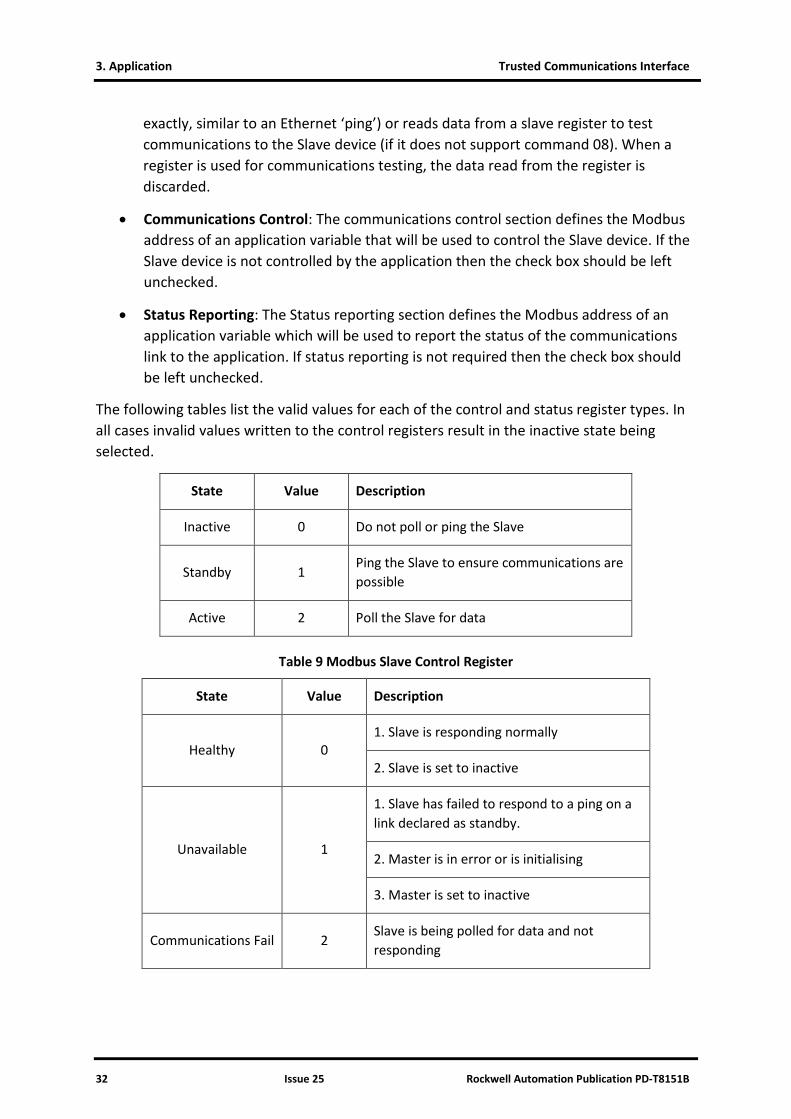
32 Issue 25 Rockwell Automation Publication PD-T8151B
exactly, similar to an Ethernet ‘ping’) or reads data from a slave register to test communications to the Slave device (if it does not support command 08). When a register is used for communications testing, the data read from the register is discarded.
• Communications Control: The communications control section defines the Modbus address of an application variable that will be used to control the Slave device. If the Slave device is not controlled by the application then the check box should be left unchecked.
• Status Reporting: The Status reporting section defines the Modbus address of an application variable which will be used to report the status of the communications link to the application. If status reporting is not required then the check box should be left unchecked.
The following tables list the valid values for each of the control and status register types. In all cases invalid values written to the control registers result in the inactive state being selected.
State Value Description
Inactive 0 Do not poll or ping the Slave
Standby 1 Ping the Slave to ensure communications are possible
Active 2 Poll the Slave for data
Table 9 Modbus Slave Control Register
State Value Description
Healthy 0 1. Slave is responding normally
2. Slave is set to inactive
Unavailable 1
1. Slave has failed to respond to a ping on a link declared as standby.
2. Master is in error or is initialising
3. Master is set to inactive
Communications Fail 2 Slave is being polled for data and not responding

Trusted Communications Interface 3. Application
Rockwell Automation Publication PD-T8151B Issue 25 33
State Value Description
Slave Error 3 Illegal values are being requested from Slave
Table 10 Modbus Slave Status Register
3.5.7. Messages Tab
Figure 12 Modbus Slave Message Configuration
This panel lists all of the messages for the Slave device in the order that the Modbus Master executes them. Dragging and dropping a highlighted message anywhere in the list can be used to change the order of the messages in the list.
To create a message to send to this Slave, click ‘New’. (‘Insert’ adds a new message at the cursor position, ‘New’ adds at the end).

3. Application Trusted Communications Interface
34 Issue 25 Rockwell Automation Publication PD-T8151B
Select a Message Type from the list. Depending on the address range and the number of addresses, the appropriate Modbus command is used. The supported commands are shown below.
Address Range Size Direction
Modbus Command
Low High Type Code
1 9999 1 Read Read Coil Status (Read Coils) 0x01
1 9999 1 Write Force single Coil (Write Coils) 0x05
1 9999 2 - 512 Read Read Coil Status (Read Coils) 0x01
1 9999 2 - 512 Write Force Multiple Coils (Write Coils) 0x15
10001 19999 1 - 512 Read Read Input Status (Read Inputs) 0x02
30001 39999 1- 125 Read Read Analogue Inputs (Read IP Registers) 0x04
40001 49999 1 - 125 Read Read Holding register (Read Registers) 0x03
40001 49999 1 Write Preset Single Register (Write Registers) 0x06
40001 49999 2 - 123 Write Preset Multiple Registers (Write Registers) 0x16
Table 11 Modbus Message Types
The Variable Network Address is the Modbus address range of the variables as mapped in the Trusted System. Only the starting address is needed; the end address is calculated automatically.
The Modbus Slave Address is the Slave’s address range for the variables. Enter the start and end addresses. The available address ranges and maximum number of addresses in a single message are shown above.
If message control is required, select ‘Application Controls Message’ and enter the Modbus address of an application variable that will be used to control the message. Where a control register is defined for either a broadcast or Slave message, the message is enabled when the register contains a zero value. All other values will result in the message being disabled. The data type used for control variable can be either Boolean or integer but not real.

Trusted Communications Interface 3. Application
Rockwell Automation Publication PD-T8151B Issue 25 35
Variable Data Type Value Message
Boolean False Enabled
True Disabled
Integer 0 Enabled
Non-zero Disabled
Table 12 Modbus Message Control Values
3.5.8. Statistics Tab
Figure 13 Modbus Slave Statistics Configuration
The statistical data records the time taken for a complete slave poll to be completed. The data is then reported to the application using a defined Modbus data variable. The value returned is an integer which represents the poll time in 1/100th second. There are three statistical values that may be returned: the maximum scan time (‘Max Scan Rate’), the average scan time (‘Average’) or the latest scan time (‘Scan Rate’). The statistics may be reset using the control variable.

3. Application Trusted Communications Interface
36 Issue 25 Rockwell Automation Publication PD-T8151B
To enable scan time statistics, select ‘Report Statistics’. Enter the Modbus address of an application variable which will be used to send the data to the application in the ‘Data’ field. Select the Statistics Type as appropriate.
Depending on the Statistics Type, the variable with the address defined in ‘Control’ has the function described below. The variable may be Boolean or integer. For Max Scan Rate and Average, a falling and rising edge sequence will restart the measurement.
Statistics Mode Control Variable Value Result
Max Scan Rate
False → True (Boolean)
0 → non-zero (Integer)
Max value will remain until next cycle completed.
Max value then updated with time of next complete cycle.
True → False (Boolean)
non-zero → 0 (Integer) Triggers a reset.
Scan Rate
False → True (Boolean)
0 → non-zero (Integer) No effect (data updated every cycle).
True → False (Boolean)
non-zero → 0 (Integer) No effect (data updated every cycle).
Average
False → True (Boolean)
0 → non-zero (Integer)
Average value will remain until next cycle completed.
Average value then updated with time of next complete cycle.
True → False (Boolean)
non-zero → 0 (Integer) Triggers a reset.
Table 13 Modbus Statistics Control
The Slave poll scan is defined as the time taken to poll a Slave for all messages in the poll list. The first message defined in the poll list is taken as the start and end point of the timing sequence.

Trusted Communications Interface 3. Application
Rockwell Automation Publication PD-T8151B Issue 25 37
This is illustrated in the diagram Figure 14 below.
Sequence No. Message Slave 1
1 Slave 1 Msg 1 Slave 2 Tstart
2 Slave 2 Msg 1 Tstart Slave 3
3 Slave 3 Msg 1 Tstart
4 Slave 1 Msg 2
5 Slave 2 Msg 2
6 Slave 3 Msg 2
7 Slave 1 Msg 3 Slave 2
8 Slave 2 Msg 1 Tstop
9 Slave 3 Msg 3
10 Slave 1 Msg 4
11 Slave 2 Msg 2 Slave 3
12 Slave 3 Msg 1 Tstop Slave 1
13 Slave 1 Msg 1 Tstop
14 Slave 2 Msg 1
15 Slave 3 Msg 2
Figure 14 Slave Poll Timing

3. Application Trusted Communications Interface
38 Issue 25 Rockwell Automation Publication PD-T8151B
3.5.9. Validation Tool
The Modbus Master Validation Tool is automatically run each time the Modbus Master configuration is saved and exited. The tool may also be run at any time by using the ‘Validate’ button on the Modbus Master main edit page.
Figure 15 Modbus Master Validation Tool
The Validation Tool scans the current configuration, checking against a rule base which matches the .INI file reader in the CI. Each violation is listed on the Validation Tool window. There is an option to ignore the errors and build the .INI file with the errors still in the configuration. This allows for partial configurations to be saved by the workbench before completion.
The rules used by the Validation Tool are listed below.
• All control registers used must be unique for all Master and Slave devices.
• All status registers used must be unique for all Master and Slave devices.
• If a Master is using Ethernet communications there must be a valid IP address specified which is not 0.0.0.0.
• No two Master devices can use the same Serial port.
• All Slave devices connected to a common Master must have unique station IDs.
• Two or more messages cannot write to the same application variable.
• Broadcast Mode control variables must be unique for all Master devices.
• When using single shot broadcast mode, a control variable must be defined.
• All statistics control and data variables must unique for all Master and Slave devices.
Trusted Communications Interface 3. Application
Rockwell Automation Publication PD-T8151B Issue 25 39
3.6. Modbus Master Polling Sequence
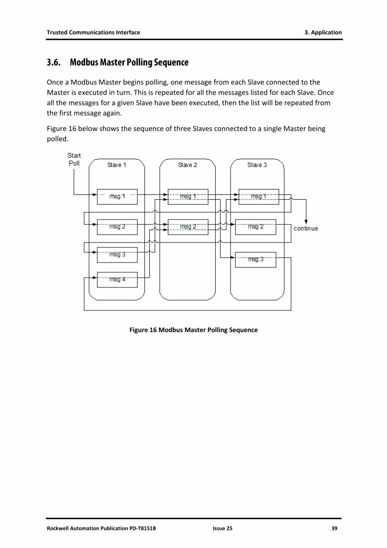
Once a Modbus Master begins polling, one message from each Slave connected to the Master is executed in turn. This is repeated for all the messages listed for each Slave. Once all the messages for a given Slave have been executed, then the list will be repeated from the first message again.
Figure 16 below shows the sequence of three Slaves connected to a single Master being polled.
Figure 16 Modbus Master Polling Sequence
3. Application Trusted Communications Interface
40 Issue 25 Rockwell Automation Publication PD-T8151B
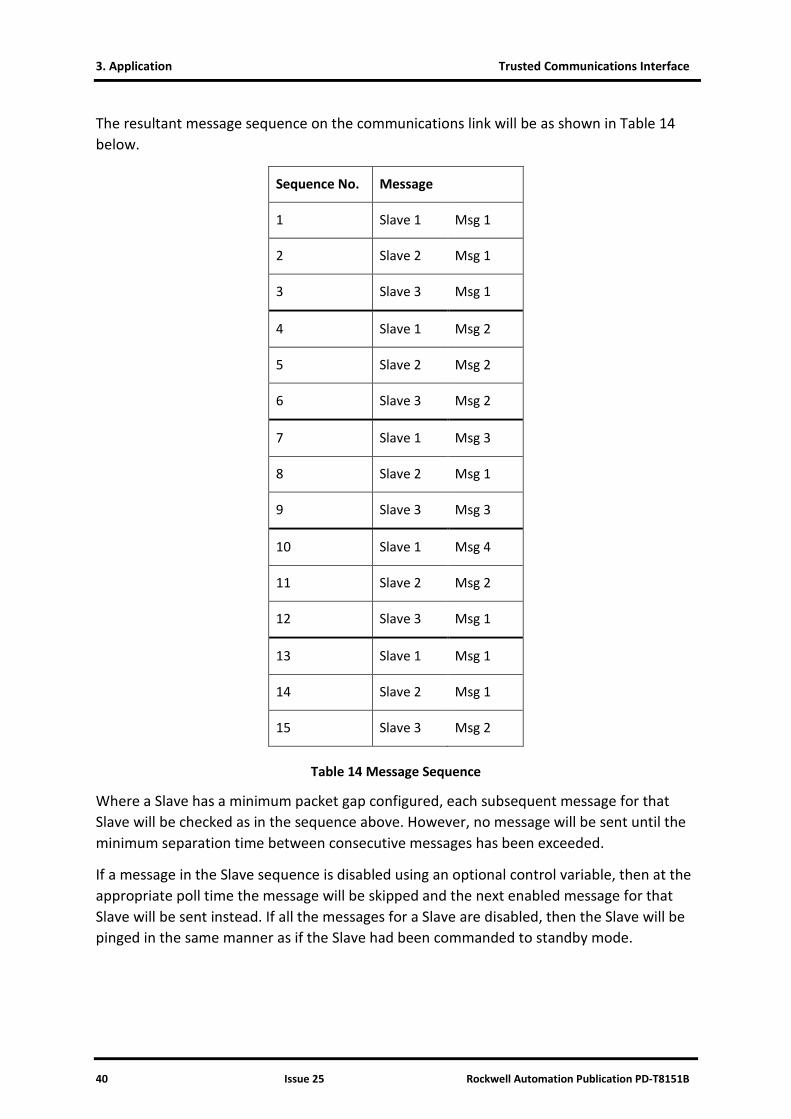
The resultant message sequence on the communications link will be as shown in Table 14 below.
Sequence No. Message
1 Slave 1 Msg 1
2 Slave 2 Msg 1
3 Slave 3 Msg 1
4 Slave 1 Msg 2
5 Slave 2 Msg 2
6 Slave 3 Msg 2
7 Slave 1 Msg 3
8 Slave 2 Msg 1
9 Slave 3 Msg 3
10 Slave 1 Msg 4
11 Slave 2 Msg 2
12 Slave 3 Msg 1
13 Slave 1 Msg 1
14 Slave 2 Msg 1
15 Slave 3 Msg 2
Table 14 Message Sequence
Where a Slave has a minimum packet gap configured, each subsequent message for that Slave will be checked as in the sequence above. However, no message will be sent until the minimum separation time between consecutive messages has been exceeded.
If a message in the Slave sequence is disabled using an optional control variable, then at the appropriate poll time the message will be skipped and the next enabled message for that Slave will be sent instead. If all the messages for a Slave are disabled, then the Slave will be pinged in the same manner as if the Slave had been commanded to standby mode.
Trusted Communications Interface 3. Application
Rockwell Automation Publication PD-T8151B Issue 25 41
3.7. Modbus Master Redundant Configurations
Redundant systems can be implemented using multiple CIs. Redundant links can also be configured from a single CI, though this will result in the module being a single point of failure. Facilities are provided to the application programmer to actively control the use of the communications links, via application network variables defined by the user in the System.INI file, as described in section 3.5.
If a Slave device fails to respond to three consecutive messages then a communications failure for that Slave will be logged (the number of messages may be configured in ‘Retries’). A communications error to a Slave device on a particular link results in the suspension of polling of that Slave for a period of time defined by the ping ‘Repeat Rate’. This allows the polling of other devices on the same Master to still be polled without pausing for the communications time-out on each cycle through the poll.
At regular intervals, the non-communicating Slave is pinged by the Master. Once the non-communicating Slave responds to a ping, then polling of the Slave will recommence on the next poll cycle. When a Slave returns to the polling sequence, the first message that will be sent to the Slave is the first message defined in the .INI file for that Slave device.
Note: A Slave replying with a Modbus exception message is not treated as having a communications failure and will not be taken out of the polling cycle.
3.8. Modbus Compatibility
The CI supports the following Modbus RTU commands.
• Read Coil Status
• Read Input Status
• Read Holding Registers
• Read Input Registers
• Force Single Coil
• Preset Single Register
• Force Multiple Coils
• Preset Multiple Registers
• Modbus 08 Command sub-function 0

3. Application Trusted Communications Interface
42 Issue 25 Rockwell Automation Publication PD-T8151B
The following coil and register mappings, as dictated by the Modbus protocol, are supported by the CI.
00001 - 10000 coils (10000 coils) read/write
10001 - 20000 digital inputs (10000 digital inputs) read only
30001 - 40000 input registers (10000 input registers) read only
40001 - 50000 holding registers (10000 holding registers) read/write
Each individual coil or register may be set to read only by checking the Write Protect option in the variable’s Extended Attributes, overriding the Modbus read/write capability. If an external Modbus Master subsequently writes to a protected coil or register, the new data value will be ignored.
The other Extended Attributes are described in PD-T8082.
3.8.1. Modbus Write Protection Compatibility
To allow for compatibility with previous versions of the module firmware, which has fixed blocks of write protected coils and registers, there is a configuration option available that reasserts this protection. When the block protection is enabled, the read/write capability of the coils and registers are defined as follows:
00001 – 7500 coils (7500 coils) read only
07501 - 10000 coils (2500 coils) read/write
40001 - 47500 holding registers (2500 holding registers) read only
47501 - 50000 holding registers (2500 holding registers) read/write
The CI does not support duplicate Modbus addresses.
3.9. Modbus Master Timing and Throughput Rules
Each Modbus message and response takes a finite time. At 9600 bits/second, a common application may take several seconds to process all transactions. The size of each transaction is listed here to allow timing calculations to be made. Note that each byte requires 11 bits for delivery, including start, parity and stop bits.

Trusted Communications Interface 3. Application
Rockwell Automation Publication PD-T8151B Issue 25 43
Detailed information on the Modbus protocol is available on www.modbus.org.
Command Request Packet Size Response Packet Size
(bytes) (bytes)
01 Read Coils 8 5, plus 1 per 8 coils (rounded up)
02 Read Discrete Inputs 8 5, plus 1 per 8 inputs (rounded up)
03 Read Holding Registers 8 5, plus 2 per register
04 Read Input Registers 8 5, plus 2 per register
05 Write Single Coil 8 8
06 Write Single Register 8 8
15 Write Multiple Coils 9, plus 1 per 8 coils (rounded up) 8
16 Write Multiple Registers
9, plus 2 per register 8
Table 15 Modbus Packet Sizes
As an example, the transfer of 1000 coils to a Slave may be performed using code 05 or code 15.
Using code 05, 1000 messages are required. Each transaction requires 16 bytes, plus the delay in either end in interpreting and preparing messages. Each transaction requires (8 + 8 bytes) x 11 = 176 bits. At 9600 bits/second, this takes 18.33 ms. If the delay is assumed to be only 1 millisecond, 100 messages take an absolute minimum of 19.33 seconds. The practical delays are likely to extend or even double this time. This configuration is also too large to program into a Communications Interface!
Using code 15, 512 coils may be set in one message. Assuming two messages of 500 coils are used, the transaction takes (9 + 500/8) + 8 bytes x 2 messages x 11 = 1,760 bits. At 9600 bits/second, this takes 183.3 ms, plus the turnaround delay. It is possible to write this data four or five times a second if both devices can process quickly. A faster data rate would also speed the communications link. The coils must however be configured in a contiguous block (without gaps). It is good practice to plan a Modbus map to include blocks of contiguous data with room for spares.
Some devices are not configured to respond to multiple write messages. If necessary, splitting the Modbus communication across more than one port or more than one CI will improve data rates and response times.

3. Application Trusted Communications Interface
44 Issue 25 Rockwell Automation Publication PD-T8151B
3.10. Modbus Slave Timing and Throughput Rules
If the Trusted System is Modbus Slave, then it has no control over the messages received from the Master. If the Trusted System is delaying more than expected between messages, it is possible that insufficient time is allowed for communications processing between the CI and the Processor. It is possible to allocate some time to background tasks like this by specifying a sleep period between scans in the system configuration.
This is especially a problem with systems that have no native I/O, e.g. bridged systems, and therefore do not have communications processing time allocated.
In the system configuration processor parameters shown below, set the sleep period to approximately 32 ms longer than the ‘current’ scan time seen in the Toolset debugger window. This will provide some time on most scans for communications tasks, and will even out the scan time. It will also lengthen the scan time, so ensure that process safety times are not compromised and the maximum scan time and I/O module watchdog times are adjusted proportionately to the change in average scan time.
Figure 17 ISaGRAF Sleep Period
For information on message timing, refer to section 3.9.
Trusted Communications Interface 3. Application
Rockwell Automation Publication PD-T8151B Issue 25 45
3.11. I/O Complex Equipment Definition ‘TCI’
The Trusted CI has a definition for entry in the I/O Connection table. For details on editing the table, please refer to PD-T8082. The definition contains no information for the application. The definition does not need to be entered into the I/O Connection table for the application to run.
OEM PARAMETERS
OEM parameter Valid numbers Description
TICS_CHASSIS TICS_SLOT
1 – 15 1 – 8 (Chassis 1) 1 – 12 (Expander Chassis)
The TICS chassis & slot number where the Communications Interface module is placed. Note that for Peer to Peer communications, the module must be in chassis 1.
CONFIGURATION
Physical module:
RACK 1: 16 ANALOGUE Inputs Input channels NOT CURRENTLY IMPLEMENTED
RACK 2: 16 ANALOGUE Outputs Output channels NOT CURRENTLY IMPLEMENTED

3. Application Trusted Communications Interface
46 Issue 25 Rockwell Automation Publication PD-T8151B
Page intentionally left blank

Trusted Communications Interface 4. Operation
Rockwell Automation Publication PD-T8151B Issue 25 47
4. Operation
4.1. Front Panel
Figure 18 shows the Front Panel of the Trusted CI. The Front Panel of the module contains indicators showing overall module health and status.
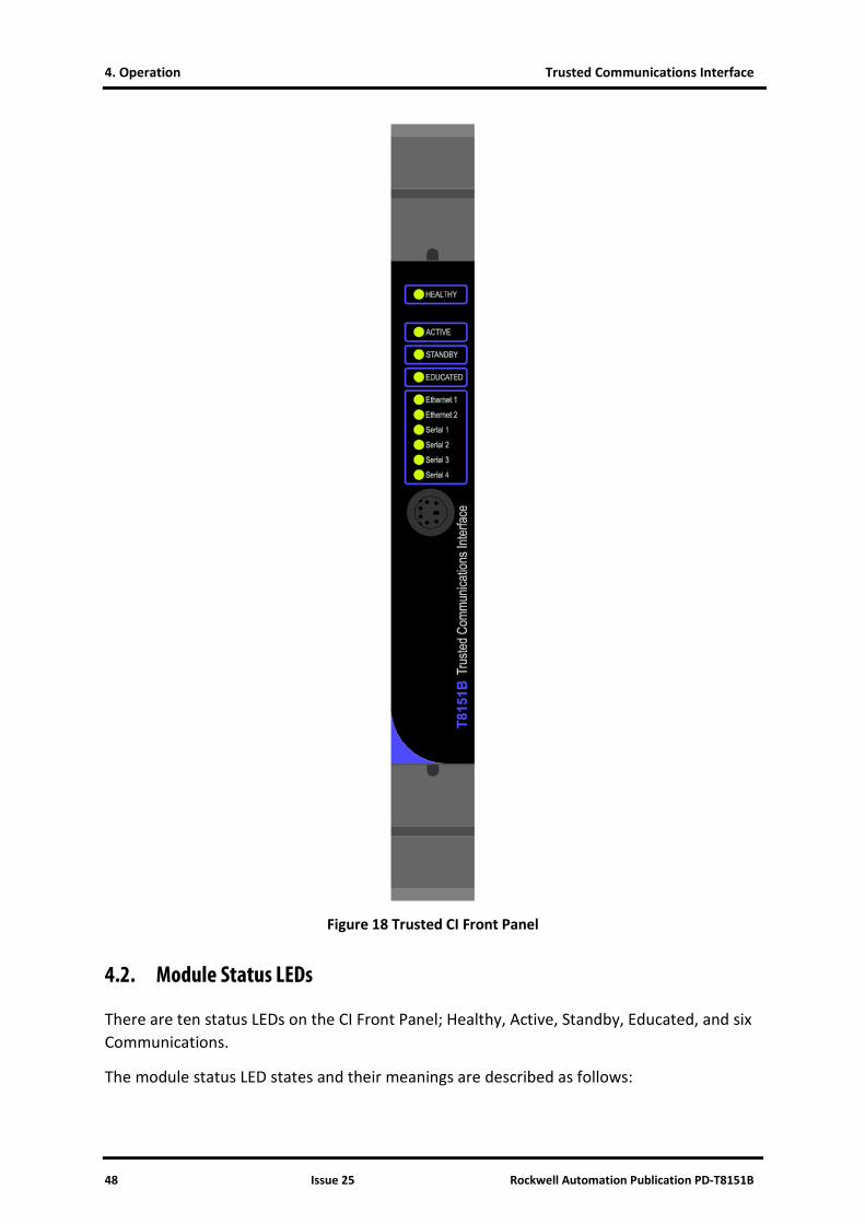
4. Operation Trusted Communications Interface
48 Issue 25 Rockwell Automation Publication PD-T8151B
Figure 18 Trusted CI Front Panel
4.2. Module Status LEDs
There are ten status LEDs on the CI Front Panel; Healthy, Active, Standby, Educated, and six Communications.
The module status LED states and their meanings are described as follows:

Trusted Communications Interface 4. Operation
Rockwell Automation Publication PD-T8151B Issue 25 49
LED INDICATION
Healthy Module health: Steady green = healthy. Flashing red = slice failed.
Active Steady green when the module is in the Active mode.
Standby Not used.
Educated Not used. Set to steady green at power-up.
Communications Six tri-coloured LEDs indicate data transfer activity on all Serial communications ports and both Ethernet ports. The LEDs flash red when responding and green when receiving. The Ethernet LEDs indicate steady green in the absence of a network connection (for 8151 up to rev H and 8151B up to rev B only)
Table 16 Pre Build C, Module Status LEDs
LED INDICATION
Healthy Module health: Steady green = healthy. Flashing red = slice failed.
Active Steady green when the module is in the Active mode (application running, communications enabled).
Standby Steady green when the module is in the Standby mode (application stopped, communications disabled).
Educated CI configuration loaded successfully from MP.
Communications Six tri-coloured LEDs indicate data transfer activity on all Serial communications ports and both Ethernet ports. The LEDs flash red when transmitting data and green when receiving and amber when transmitting and receiving.(T8151B rev C onwards)
Table 17 Build C, Module Status LEDs
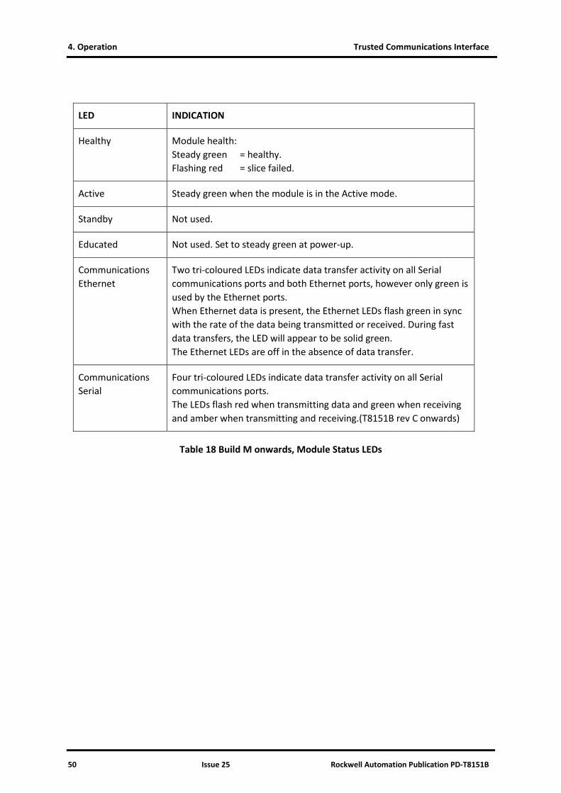
4. Operation Trusted Communications Interface
50 Issue 25 Rockwell Automation Publication PD-T8151B
LED INDICATION
Healthy Module health: Steady green = healthy. Flashing red = slice failed.
Active Steady green when the module is in the Active mode.
Standby Not used.
Educated Not used. Set to steady green at power-up.
Communications Ethernet
Two tri-coloured LEDs indicate data transfer activity on all Serial communications ports and both Ethernet ports, however only green is used by the Ethernet ports. When Ethernet data is present, the Ethernet LEDs flash green in sync with the rate of the data being transmitted or received. During fast data transfers, the LED will appear to be solid green. The Ethernet LEDs are off in the absence of data transfer.
Communications Serial
Four tri-coloured LEDs indicate data transfer activity on all Serial communications ports. The LEDs flash red when transmitting data and green when receiving and amber when transmitting and receiving.(T8151B rev C onwards)
Table 18 Build M onwards, Module Status LEDs
Trusted Communications Interface 5. Fault Finding and Maintenance
Rockwell Automation Publication PD-T8151B Issue 25 51
5. Fault Finding and Maintenance
5.1. Fault Reporting
The CI provides a module fault alarm on its Healthy LED, which indicates a module shutdown. No diagnostics are available via the module’s I/O complex equipment definition. Diagnostic variables are available for Modbus Master configurations as described in section 3.5. Detailed communications diagnostics are available via the command line interface diagnostics as described in section 5.4
5.2. Module Faults
The CI is a simplex module. There are triplicated voting circuits for interfacing to the system Inter-Module Bus, but the remaining architecture has no redundant circuits. The CI is certified as non-interfering and fail safe. On failure of the processing circuits or on communications conditions that the module cannot cope with, the module will shut down. Safety related communications require two CIs providing the same services on separate data links.
5.3. Module Replacement
The CI cannot be hot swapped. If the module has shut down or communications through the module has stopped, the module should be removed from the chassis and then re-inserted into the chassis. It will automatically restart and load its communications settings online.
The module performs a warm-start on an application load, a configuration download and an online update and will then operate with the latest communications configuration.
5.4. Command Line Diagnostics
The CI has a front-panel mounted RS232 Serial diagnostic port to which the Engineering Workstation or a laptop PC can be connected. The diagnostic port also provides an interface to the diagnostics and online monitoring facilities of the Trusted TMR Processor. This facility is provided for the use of ICS Triplex personnel.
The command line diagnostic interface requires a TC-304-02 Maintenance Cable and a terminal program such as Hyperterminal or Teraterm. The Serial port settings default to 19200baud, 8 data bits, 1 stop bit and no parity. The module will reply to ‘Enter’ with its command line prompt ci:?.

5. Fault Finding and Maintenance Trusted Communications Interface
52 Issue 25 Rockwell Automation Publication PD-T8151B
5.4.1. Top Level Commands
Top level help is obtained by typing h, to either the CI or the Processor.
Diagnostics Interface Commands:
t - List tasks registered with Diagnostics
v - List module configuration.
h - Display this help screen.
su - Establish super-user privilege.
. - Close established privilege/connection.
- If no arguments, establish connection.
ci:?
The module build data is shown on typing v.
FIRMWARE CONFIGURATION:
8151 CI O/S Firmware
353570 Build 115
Copyright (c)1997-2006 ICS Triplex Technology
Copyright (c)2003 Enea OSE Systems AB
HARDWARE CONFIGURATION:
Processor revision - 0x80811014
EPLD revision - 0x00000001
ci:?
Password protected super user privileges (su) are required in the Processor, primarily to connect to I/O module command line interfaces and for some of the more invasive commands in the CI. These commands are marked with (!).
5.4.2. Task Commands
Operating system tasks (processes) which have command line diagnostics report their presence on typing t. This is the route to all further CI diagnostics. This top level command lists all tasks which respond to commands. Note that these tasks and their commands change with firmware builds, and therefore there is no separate documentation of all task command interfaces.
Tasks Registered with Diagnostics
Registered Task Name Prefix Commands
Trace Diagnostics trc e,d,c,dm,a,h,.
IMB Diagnostics imb h,p
Peer I/O Comms pio s,p,h
Dual Peer I/O dxp s,h
Front Panel Services fps q,d,r,h
Log Server ls h,d,l,b,k
Modbus Slave mbs s,p,r,e,h
Network Variable Manager nvm s,h,r,l
Comms File System cfs l,i,c,d,s,h

Trusted Communications Interface 5. Fault Finding and Maintenance
Rockwell Automation Publication PD-T8151B Issue 25 53
UART Connection Manager uart s,r,h
Modbus Master mbm m,s,t,b,l,c,cont,stat,caddr,sadd
TCP Connection Manager tcp s,p,r,ns,ne,nr,close,clog,diag,h
Remote Diagnostics I/F 1.15 h,...
ci:?
Each task will provide help on its commands on typing the task prefix. For example, Modbus Master commands are shown below. To enter a command, type its prefix, a space and the command, e.g. mbm m.
ci:?mbm
Modbus Master Diagnostic Commands:
m - Displays Master Configuration [master].
s - Displays Slave Configuration [slave].
t - Displays Message Configuration [slave].
b - Displays Broadcast Message Configuration [master].
l - Controls diagnostic logging [all|m|son|off]
c - Displays communications logs [r][all|m|s]
cont - (!)Set the value in the control register for slave or master.
stat - (!)Set the value in the status register for slave or master.
caddr - (!)Set the address of the control register for slave or master.
saddr - (!)Set the address of the status register for slave or master.
h - Displays this help message.
ci:?
Some useful commands are listed below.
ls d Show current event log
ls b Show backup event log before last power loss (only from hardware build C)
pio s Simplex peer link status (errors, connections)
pio p n Status of peer number n (packet counts errors, IP address etc.)
dxp s Dual per link status
fps r Press the reset pushbutton
fps q Displays current date and time in proper format
fps d <date> <time> Set the date and time in the format yyyy-mm-dd hh:mm:ss
mbs s Modbus Slave packet counts and errors
mbs p Modbus Slave port setup

5. Fault Finding and Maintenance Trusted Communications Interface
54 Issue 25 Rockwell Automation Publication PD-T8151B
uart s Serial port setup
mbm m Modbus Master setup for each Master
mbm s Modbus Master setup for each Slave
mbm t Modbus Master setup for each message sent to/from Slaves
mbm c Modbus Master communications statistics
tcp s Ethernet port connection status (note the connections and the ports they use)
tcp p Ethernet port configuration
tcp ns Ethernet general statistics: number of packets, error counts
tcp ne Ethernet detailed network errors
tcp diag on Open diagnostic port over Ethernet
tcp diag off Close diagnostic port over Ethernet
These last two commands have been highlighted because they open and close the ability to connect command line diagnostics over an Ethernet link. This will allow a site engineering workstation to access these diagnostic commands across a network, and avoids the need to physically plug into the system. By default, the Ethernet diagnostics are disabled for security.
5.4.3. Hierarchical Prompts
Some tasks actually provide a second layer prompt; the prompt will change on typing the prefix. To disconnect from these prompts, type a full stop/period ‘.’ In the CI, tasks trc and 1.15 connect to a new prompt layer.
1.15 opens access to the Processor. The command line interface is then routed through to the active Processor. Similar commands route communications from the processor to a standby Processor and to CIs. It is possible to connect to the Processor and back again using these commands; note that these connections should be closed with ‘.’ before disconnecting.
5.4.4. Trace Diagnostics
trc provides access to trace diagnostics (activity logging). Once in the trc:? prompt, there is no need to type trc before each command. Most of the trace diagnostics are for R&D use only, but the c command may be useful for capturing communications data.

Trusted Communications Interface 5. Fault Finding and Maintenance
Rockwell Automation Publication PD-T8151B Issue 25 55
Communications data may be filtered, but the filtering is based on internal numbers for ports and sockets, not any obvious pattern. The first step therefore is to capture all data and identify the socket and port numbers for the data of interest.
Type ‘c’ to check that filtering is turned off. The three filters should show [off].
trc:?c
Comms logging disabled
Socket filter : [off]
Peer port filter : [off]
Peer IP address filter: [off]
Comms. log empty.
trc:?
Type ‘c 1’ to collect one buffer (128 packets) of communications.
Type ‘c’ to check on the state of the buffer. Repeat this until the buffer has reached 128 packets.
trc:?c
Comms logging enabled - single shot
Socket filter : [off]
Peer port filter : [off]
Peer IP address filter: [off]
128 packets recorded (full)
Type ‘c off’ to stop collection.
Type ‘c d’ to display the buffer. An example segment is shown here with an OPC server on port 2446 and a Modbus Master on Serial port 1. For this example, the Modbus Master will be examined. This is socket 1, IP 0.0.0.0 and port 0.
12:16:52.063 Tx Socket:1 IP:0.0.0.0 Port:0 Length:8
01 08 00 00 55 55 1F 64
12:16:52.140 Rx Socket:6 IP:192.200.81.140 Port:2446 Length:20
01 11 F0 00 00 0B 0B 73 6F 65 6C 6F 67 2E 63 62
66 00 2B 50
12:16:52.140 Tx Socket:6 IP:192.200.81.140 Port:2446 Length:8
01 11 F0 00 00 0B 8F 0E
12:16:52.155 Rx Socket:6 IP:192.200.81.140 Port:2446 Length:13
01 11 F0 02 00 04 04 00 00 00 00 27 D1
12:16:52.156 Tx Socket:6 IP:192.200.81.140 Port:2446 Length:8
01 11 F0 02 00 04 6E CA
12:16:52.171 Rx Socket:6 IP:192.200.81.140 Port:2446 Length:8
01 12 00 00 00 50 B9 F5
To filter for socket number 1, type ‘c sock 1’. The log can also filter for port and IP (e.g. ‘c ip 0.0.0.0’). Choose filter settings that isolate the desired communications.
Then start the collection again, either a single fill ‘c 1’ or fill continuously until stopped ‘c on’. Type ‘c’ to check the size of the buffer.

5. Fault Finding and Maintenance Trusted Communications Interface
56 Issue 25 Rockwell Automation Publication PD-T8151B
When the buffer is full or an event has occurred that needs capturing, type ‘c off’. Type ‘c d’ to display the buffer, which will now only show the filtered communications.
c d
WED 2007-11-21
12:26:34.717 Tx Socket:1 IP:0.0.0.0 Port:0 Length:8
01 08 00 00 55 55 1F 64
12:26:35.743 Tx Socket:1 IP:0.0.0.0 Port:0 Length:8
01 08 00 00 55 55 1F 64
12:26:36.768 Tx Socket:1 IP:0.0.0.0 Port:0 Length:8
01 08 00 00 55 55 1F 64
12:26:37.788 Tx Socket:1 IP:0.0.0.0 Port:0 Length:8
01 08 00 00 55 55 1F 64
12:26:38.813 Tx Socket:1 IP:0.0.0.0 Port:0 Length:8
01 08 00 00 55 55 1F 64
12:26:39.840 Tx Socket:1 IP:0.0.0.0 Port:0 Length:8
01 08 00 00 55 55 1F 64
12:26:40.864 Tx Socket:1 IP:0.0.0.0 Port:0 Length:8
01 08 00 00 55 55 1F 64
12:26:41.886 Tx Socket:1 IP:0.0.0.0 Port:0 Length:8
01 08 00 00 55 55 1F 64
12:26:42.909 Tx Socket:1 IP:0.0.0.0 Port:0 Length:8
01 08 00 00 55 55 1F 64
------- End of Log -------

Trusted Communications Interface 6. Communications Wiring
Rockwell Automation Publication PD-T8151B Issue 25 57
6. Communications Wiring
6.1. RS232 Communications Standard
There are two main classes of Serial communication defined in the RS232 standard.
• DTE (Data Terminal Equipment), such as terminals and computers.
• DCE (Data Communications Equipment), such as modems.
If standard D-type connectors are used, the convention is to mount female connectors on the DCE devices and male connectors on the DTE devices. Cables between DCE and DTE devices can be connected 1:1. Cables between devices of the same class require cross-over or ‘Null modem’ cables.
Note that the signal names are from the viewpoint of the DTE. E.g. Transmit Data is sent by the DTE, but received by DCE.
The CI is configured as a DTE class device.
Table 19 below shows the signal directions for the common RS232 circuits.
Circuit Name Direction
TXD DTE → DCE
RXD DTE ← DCE
RTS DTE → DCE
CTS DTE ← DCE
GND
DSR DTE ← DCE
DCD DTE ← DCE
DTR DTE → DCE
RI DTE ← DCE
Table 19 Signal Directions for RS232 Circuits
Table 20 below shows some alternatives for the wiring of port 1 when using a cable. Note that a male connector is specified on the cable for connection to the female connector of a DCE device and a female connector is specified for connection to the male connector of a

6. Communications Wiring Trusted Communications Interface
58 Issue 25 Rockwell Automation Publication PD-T8151B
DTE device. Note that the labels in the FROM section are shown the same as those on Product Descriptions PD-T8151B and PD-T8153. Please refer to these product descriptions for further information on cable wiring.
Cable TC–305–01 (or –02) connects to the CI module field socket PL5 and extends the ports below to flying leads. Please refer to Product Description PD-TC300 for further details.
From To
CI (PL5) Interface Adapter (J3)
9 Way D-type 25 Way D-type
DIN41612 Socket
9 way Phoenix Contact Socket
To DTE (Socket)
To DCE (Plug)
To DTE (Socket)
To DCE (Plug)
A5 (TXD1) 1 (TXD) 2 (RXD) 3 (TXD) 3 (RXD) 2 (TXD)
C6 (RXD1) 2 (RXD) 3 (TXD) 2 (RXD) 2 (TXD) 3 (RXD)
A6 (RTS1)* 3 (RTS)* 8 (CTS) 7 (RTS) 5 (CTS) 4 (RTS)
A7 (CTS1)* 4 (CTS)* 7 (RTS) 8 (CTS) 4 (RTS) 5 (CTS)
C9 (GND1) 5 (GND) 5 (GND) 5 (GND) 7 (GND) 7 (GND)
B7 (DSR1)* 6 (DSR)* 4 (DTR) 6 (DSR) 20 (DTR) 6 (DSR)
C7 (DCD1)* 7 (DCD)* 4 (DTR) 1 (DCD) 20 (DTR) 8 (DCD)
B6 (DTR1)* 8 (DTR)* 6(DSR) 4 (DTR) 6 (DSR) 20 (DTR)
B6 (DTR1)* 8 (DTR)* 1(DCD) - 8 (DCD) -
C8 (RI1)* 9 (RI)* Not Connected
9 (RI) Not Connected
22 (RI)
* Signals shown for completeness only, not used in the CI.
Table 20 Cable Wiring for CI Port 1
Note: GND refers to Signal Ground. This should not be connected to chassis ground e.g. Pin 1 on 25 Way D-types.

Trusted Communications Interface 6. Communications Wiring
Rockwell Automation Publication PD-T8151B Issue 25 59
Table 21 below shows some alternatives for the wiring for Port 2 when using a cable.
From To
Communications Interface (PL5)
Interface Adapter (J7)
9 Way D-type 25 Way D-type
DIN41612 Socket 5 way Phoenix Contact Socket
To DTE (Socket)
To DCE (Plug)
To DTE (Socket)
To DCE (Plug)
A11 (TXD2) 1 (TXD) 2 (RXD) 3 (TXD) 3 (RXD) 2 (TXD)
C11 (RXD2) 2 (RXD) 3 (TXD) 2 (RXD) 2 (TXD) 3 (RXD)
B11 (RTS2)* 3 (RTS)* 8 (CTS) 7 (RTS) 5 (CTS) 4 (RTS)
C12 (CTS2)* 4 (CTS)* 7 (RTS) 8 (CTS) 4 (RTS) 5 (CTS)
C13 (GND2) 5 (GND) 5 (GND) 5 (GND) 7 (GND) 7 (GND)
* Signals shown for completeness only, not used in the Communications Interface.
Table 21 Cable Wiring for CI Port 2
Note: GND refers to Signal Ground. This should not be connected to chassis ground e.g. Pin 1 on 25 Way D-types.
Figure 19 below shows the connection of the CI Front Panel Port. This also applies to the Processor Front Panel Port. These are normally connected using a TC-304-01 Maintenance Cable.
Pin Function (DTE)
MP SK1 connection
1 RTS
2 TXD E14
3 RXD E16
4 CTS
5 GND
6 unconnected
Figure 19 MP and CI Front Panel Diagnostic Ports

6. Communications Wiring Trusted Communications Interface
60 Issue 25 Rockwell Automation Publication PD-T8151B
6.1.1. Maximum Cable Length
The RS232 standard states that the maximum capacitive load seen by the driver should be 2500 pF. The maximum length of cable can be worked out from the capacitance specification of the cable being used. For example, EIA Category 5 cable is rated at 17 pF/ft so the maximum cable length will be 2500/17 = 147 ft (approx. 45 m). The maximum data rate for RS232 is 20 kbits/s (i.e. 19K2). As a general rule, cable length may double if the data rate halves.
6.2. RS485 Communications Standard
RS485 is a differential twisted pair interface. A key feature of RS485 over RS422 is its ability to support configurations where multiple line-drivers share a common twisted pair, as distinct from multi-drop (i.e. multiple receivers only) which is supported by both RS422 and RS485. There are several modes of operation for the RS485/RS422 ports of the CI.
6.2.1. RS485 Full Duplex
This mode is a 4 wire point to point connection. The System Configuration setting for this mode is ‘rs485fd’.
The receive end of the link should always be terminated. The CI shall be AC terminated with a 120 Ω resistor and 68 nF capacitor in series across the receive pair. The Interface Adapter (8153 for the CI and 8130 for the MP) provides link selectable terminations for the receive circuit.
A diagram of the topology is shown in Figure 20 below.
A
B
TX
A
B
RX
A
B
TX
A
B
RX
Term
Term
Figure 20 RS485 Full Duplex Topology

Trusted Communications Interface 6. Communications Wiring
Rockwell Automation Publication PD-T8151B Issue 25 61
6.2.2. RS485 Full Duplex Multiplexed
This mode is a 4 wire multi-drop connection. The System Configuration setting for this mode is ‘rs485fdmux’.
On circuits with multiple transmitters the line should be terminated at both ends. On circuits with one transmitter the line should be terminated at the far end (usually the last receiver in the chain). The Interface Adapter (T8153) provides links for termination on the receiver and transmitter circuit.
A diagram of the topology is shown in Figure 21 below.
A
B
RX
A
B
TX
AB
RX
AB
TX
Term
AB
TX
AB
RX
AB
TX
AB
RX
Term
Term
Figure 21 RS422 Full Duplex Multi-drop Topology
The maximum number of nodes that the CI supports before hardware build C for multi-drop applications is 6. From hardware build C, the module has internal terminations changed to support the full 32 drop capacity.
6.2.3. RS485 Half Duplex Multiplexed
This mode is a 2 wire multi-drop connection. The System Configuration setting for this mode is ‘rs485hdmux’.
As this configuration contains multiple transmitters on the same circuit there should be terminations at both ends. The Interface Adapter (T8153) provides links for both terminations since the receive and transmit are multiplexed onto the ‘Receive Circuit’.

6. Communications Wiring Trusted Communications Interface
62 Issue 25 Rockwell Automation Publication PD-T8151B
A diagram of the topology is shown in Figure 22 below.
A
B
RX
A
B
TX
AB
RX
AB
RX
AB
RX
AB
TX
AB
TX
AB
TX
Term
Term
Figure 22 Half Duplex Multiplexed Topology
The maximum number of nodes that the CI supports before hardware build C for multi-drop applications is 6. From hardware build C, the module has internal terminations changed to support the full 32 drop capacity.
6.2.4. Signal Ground
The topologies shown in the previous diagrams do not show the Signal Ground for reasons of clarity. On all the above circuits, Signal Ground must be connected for correct operation. It is also important not to connect the signal ground to the chassis ground. The Signal Grounds for each port on the CI should be kept separate from each other to maintain the isolation between ports. It is recommended that when specifying cables that an extra twisted pair is specified to carry the signal ground connection. Signal ground should not be connected to the cable screen because the cable screen should be used for EMI shielding and should be connected to chassis ground.
6.2.5. A and B Circuit Designators
The ‘A’ and ‘B’ circuit designators are often a source of confusion for systems integrators. This is not helped by the use of non-standard ‘+’ and ‘-’ symbols on some equipment.
To determine which terminal is ‘A’ and which is ‘B’, set the line to the ‘Idle’ or ‘Off’ state. Connect a multimeter on the volts range across the ‘A’ and ‘B’ terminals. When the multimeter reads a negative voltage, the +ve terminal of the multimeter is connected to ‘A’ and the -ve terminal is connected to ‘B’.
The ‘+’ and ‘-’ symbols shown on some equipment are rarely very reliable at indicating which circuit is which unless connecting equipment of the same make together. There is no
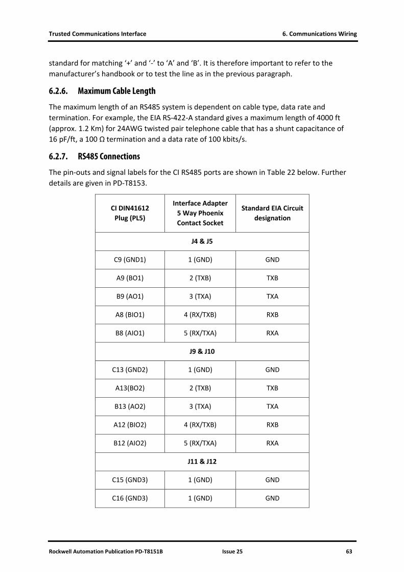
Trusted Communications Interface 6. Communications Wiring
Rockwell Automation Publication PD-T8151B Issue 25 63
standard for matching ‘+’ and ‘-’ to ‘A’ and ‘B’. It is therefore important to refer to the manufacturer’s handbook or to test the line as in the previous paragraph.
6.2.6. Maximum Cable Length
The maximum length of an RS485 system is dependent on cable type, data rate and termination. For example, the EIA RS-422-A standard gives a maximum length of 4000 ft (approx. 1.2 Km) for 24AWG twisted pair telephone cable that has a shunt capacitance of 16 pF/ft, a 100 Ω termination and a data rate of 100 kbits/s.
6.2.7. RS485 Connections
The pin-outs and signal labels for the CI RS485 ports are shown in Table 22 below. Further details are given in PD-T8153.
CI DIN41612 Plug (PL5)
Interface Adapter 5 Way Phoenix Contact Socket
Standard EIA Circuit designation
J4 & J5
C9 (GND1) 1 (GND) GND
A9 (BO1) 2 (TXB) TXB
B9 (AO1) 3 (TXA) TXA
A8 (BIO1) 4 (RX/TXB) RXB
B8 (AIO1) 5 (RX/TXA) RXA
J9 & J10
C13 (GND2) 1 (GND) GND
A13(BO2) 2 (TXB) TXB
B13 (AO2) 3 (TXA) TXA
A12 (BIO2) 4 (RX/TXB) RXB
B12 (AIO2) 5 (RX/TXA) RXA
J11 & J12
C15 (GND3) 1 (GND) GND
C16 (GND3) 1 (GND) GND

6. Communications Wiring Trusted Communications Interface
64 Issue 25 Rockwell Automation Publication PD-T8151B
CI DIN41612 Plug (PL5)
Interface Adapter 5 Way Phoenix Contact Socket
Standard EIA Circuit designation
A16 (BO3) 2 (TXB) TXB
B16 (AO3) 3 (TXA) TXA
A15 (BIO3) 4 (RX/TXB) RXB
B15 (AIO3) 5 (RX/TXA) RXA
J13 & J14
C18 (GND4) 1 (GND) GND
C19 (GND4) 1 (GND) GND
A19 (BO4) 2 (TXB) TXB
B19 (AO4) 3 (TXA) TXA
A18 (BIO4) 4 (RX/TXB) RXB
B18 (AIO4) 5 (RX/TXA) RXA
Table 22 CI Cable Wiring for RS485
Notes: Labels are shown the same as those on the Product Descriptions. RX/TX = Receive circuit in 4 wire applications. Multiplexed circuit for 2 wire applications. GND = Signal Ground. There are actually 2 identical connectors on the Interface Adapter for each port. This is to allow either side of multi-drop connections to be connected to separate connectors. No ‘To’ connections have been shown as there is no standard connector for RS485 and many devices have terminal blocks for the connections.
6.3. Ethernet – 10Base2
10Base2 Ethernet is a linear network with nodes fitted along the length of one network; it cannot cope with spurs. The connections use 50 Ω coax cables (e.g. RG58). The rules for connecting 10Base2 Ethernet are given below.
• The maximum length of a segment without repeaters is 185 m.
• A maximum of 4 repeaters are allowed to extend a segment, where the cable length between the repeaters is less than or equal to that of a non-repeated cable segment and 2 segments must be links only (i.e. no connections apart from the 2 repeaters).

Trusted Communications Interface 6. Communications Wiring
Rockwell Automation Publication PD-T8151B Issue 25 65
• The maximum number of nodes on a segment is 30 and includes any repeaters.
• There should be a minimum of 0.5 m between nodes.
• Each cable segment must be terminated at either end with a 50 Ω termination.
• The connections to each device must be by T-connectors directly onto the BNC jack provided. A spur from the network to the device will cause reflections in the cabling and stop the network working correctly.
• The screen of a segment may be earthed for safety reasons if required, but only at one point on the segment.
• If connecting to a CI via the Interface Adapter, the T-connection must plug directly into the BNC jacks on the bottom of the unit.
• If wiring a connector directly onto the back of the CI DIN41612 connector, keep the lead to the BNC jack as short as possible, i.e. just long enough to come out of the backshell and no longer (the Ethernet standard recommends no more than 4 cm).
Note: 10Base2 is not available on CI modules after build C.
6.4. Ethernet – 10BaseT/100BaseT
The 10BaseT/100BaseT Ethernet connections normally use unshielded twisted pair cable (EIA Category 3 (‘Cat3’) or better for 10BaseT and ‘Cat5’ for 100BaseT). The standard connector is the 8 pin RJ45 jack. The rules for connecting 10BaseT Ethernet are given below.
• 10/100BaseT Ethernet is a ‘star’ network. A point to point link between two nodes may be made with a single cable. Multiple nodes require a central device to connect nodes together. A hub relays data packets to all nodes. A switch intelligently routes data packets only to the intended recipient.
• The maximum length of a (copper) segment is 100 m with the cable grades listed above. Longer distances are usually converted to fibre.
• Only use twisted pair cable. Non twisted pair can degrade network performance severely.
When connecting equipment to a hub or switch, use a standard straight (pin to pin) cable. If connecting equipment together (e.g. CI directly to a PC, or PC to PC) then a crossover cable is required. A crossover cable is sometimes also required to connect two hubs/switches if they do not auto-detect the connection, and some devices have a selection switch.
Note: The Ethernet standard states that hub/switch ports that are internally crossed over (and therefore only need straight cables) should be marked with an ‘x’.
The CI module Ethernet ports do not auto-detect the cable wiring, as switches do. This may result in problems if both ends drive the same cable pair, because the drivers can latch up
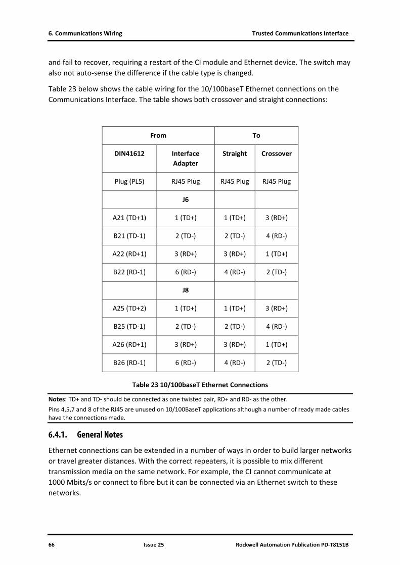
6. Communications Wiring Trusted Communications Interface
66 Issue 25 Rockwell Automation Publication PD-T8151B
and fail to recover, requiring a restart of the CI module and Ethernet device. The switch may also not auto-sense the difference if the cable type is changed.
Table 23 below shows the cable wiring for the 10/100baseT Ethernet connections on the Communications Interface. The table shows both crossover and straight connections:
From To
DIN41612 Interface Adapter
Straight Crossover
Plug (PL5) RJ45 Plug RJ45 Plug RJ45 Plug
J6
A21 (TD+1) 1 (TD+) 1 (TD+) 3 (RD+)
B21 (TD-1) 2 (TD-) 2 (TD-) 4 (RD-)
A22 (RD+1) 3 (RD+) 3 (RD+) 1 (TD+)
B22 (RD-1) 6 (RD-) 4 (RD-) 2 (TD-)
J8
A25 (TD+2) 1 (TD+) 1 (TD+) 3 (RD+)
B25 (TD-1) 2 (TD-) 2 (TD-) 4 (RD-)
A26 (RD+1) 3 (RD+) 3 (RD+) 1 (TD+)
B26 (RD-1) 6 (RD-) 4 (RD-) 2 (TD-)
Table 23 10/100baseT Ethernet Connections
Notes: TD+ and TD- should be connected as one twisted pair, RD+ and RD- as the other. Pins 4,5,7 and 8 of the RJ45 are unused on 10/100BaseT applications although a number of ready made cables have the connections made.
6.4.1. General Notes
Ethernet connections can be extended in a number of ways in order to build larger networks or travel greater distances. With the correct repeaters, it is possible to mix different transmission media on the same network. For example, the CI cannot communicate at 1000 Mbits/s or connect to fibre but it can be connected via an Ethernet switch to these networks.

Trusted Communications Interface 6. Communications Wiring
Rockwell Automation Publication PD-T8151B Issue 25 67
There are a number of issues involved in building multiple segment and mixed media networks that are beyond the scope of this document. Further information can be found in the Ethernet standards.
Although Ethernet communications is ubiquitous in industrial and office networks, it is recommended that safety-related communications (and any industrial communications considered critical to production) are kept separate from general office communications because the load on the general network due to office communications will be unpredictable.
6.4.2. Network Reflections
If two networks are connected together via a router or some other method which allows packets to transfer between the networks, it is possible for one network to pass the data to the second and then the second network to pass the data to the first network knowing that the first network contains that IP. If this happens, the same data will bounce back and forth between the networks. Most data packets have a transfer count limit (‘time to live’) of 32, 64 or 128 transfers. For example, if it is set to 32 it will only go through 32 routers and then the packet will be discarded. If each network has 1 router and the networks are connected together, every data packet sent to a particular CI module will arrive at the module 16 times and hence require 16 times the processing. If is set to 128, it will give 64 times the loading. This problem is made worse when a switch or any other connection sends a broadcast message (e.g. updating its IP connection table). This will bounce to all nodes at least 16 times on top of the normally traffic x 16. The TTL (time to live) cannot be controlled by the application and it may even be a router broadcast packet that is causing the problem.
If the above happens, the CIs will be overloaded and may crash on releases before 3.5. From release 3.5, although the CIs will continue to operate, peer to peer network timeouts are likely to occur instead, which will cause a trip in the application if safety related data is being carried.
The CIs will not transfer packets between networks. However, it is possible for PCs to transfer packets through IP forwarding/routing. To disable this, set the following registry entry to zero:
\HKLM\SYSTEM\CurrentControlSet\Services\Tcpip\Parameters IPEnableRouter
6.4.3. Network Load
It is also possible to overload the CIs by using too fast a poll rate on the OPC server. The poll variables are divided into two groups: those that have SOE or Process Historian enabled (Sequence of Events Update and Process Historian Update), and the Modbus data that does not have SOE (Global Ungrouped Tag Update). The product description for the OPC Server describes loading and timing calculations.
An Ethernet link should be designed to be less than 30 % loaded.
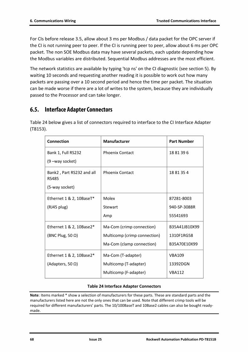
6. Communications Wiring Trusted Communications Interface
68 Issue 25 Rockwell Automation Publication PD-T8151B
For CIs before release 3.5, allow about 3 ms per Modbus / data packet for the OPC server if the CI is not running peer to peer. If the CI is running peer to peer, allow about 6 ms per OPC packet. The non SOE Modbus data may have several packets, each update depending how the Modbus variables are distributed. Sequential Modbus addresses are the most efficient.
The network statistics are available by typing 'tcp ns' on the CI diagnostic (see section 5). By waiting 10 seconds and requesting another reading it is possible to work out how many packets are passing over a 10 second period and hence the time per packet. The situation can be made worse if there are a lot of writes to the system, because they are individually passed to the Processor and can take longer.
6.5. Interface Adapter Connectors
Table 24 below gives a list of connectors required to interface to the CI Interface Adapter (T8153).
Connection Manufacturer Part Number
Bank 1, Full RS232
(9 –way socket)
Phoenix Contact 18 81 39 6
Bank2 , Part RS232 and all RS485
(5-way socket)
Phoenix Contact 18 81 35 4
Ethernet 1 & 2, 10BaseT*
(RJ45 plug)
Molex
Stewart
Amp
87281-8003
940-SP-3088R
55541693
Ethernet 1 & 2, 10Base2*
(BNC Plug, 50 Ω)
Ma-Com (crimp connection)
Multicomp (crimp connection)
Ma-Com (clamp connection)
B35A41JB10X99
1310F1RG58
B35A70E10X99
Ethernet 1 & 2, 10Base2*
(Adapters, 50 Ω)
Ma-Com (T-adapter)
Multicomp (T-adapter)
Multicomp (F-adapter)
VBA109
13392DGN
VBA112
Table 24 Interface Adapter Connectors
Note: Items marked * show a selection of manufacturers for these parts. These are standard parts and the manufacturers listed here are not the only ones that can be used. Note that different crimp tools will be required for different manufacturers’ parts. The 10/100BaseT and 10Base2 cables can also be bought ready-made.

Trusted Communications Interface 6. Communications Wiring
Rockwell Automation Publication PD-T8151B Issue 25 69

6. Communications Wiring Trusted Communications Interface
70 Issue 25 Rockwell Automation Publication PD-T8151B
6.6. Further Sources of Information
EIA/TIA-232-E RS232 Standard
EIA/TIA-422-B RS422 Standard
EIA-485 RS485 Standard
IEEE 802.3 Ethernet Standard
Note: EIA/TIA = Electronics Industry Association/Telecommunications Industry Association. IEEE = Institute of Electrical and Electronic Engineers.

Trusted Communications Interface 6. Communications Wiring
Rockwell Automation Publication PD-T8151B Issue 25 71
Page intentionally left blank

Trusted Communications Interface 7. SOE Over Modbus Protocol
Rockwell Automation Publication PD-T8151B Issue 25 72
7. SOE Over Modbus Protocol
The SOE Over Modbus Protocol is defined in two parts: the definition of the Modbus registers within the SOE Address Window, and the defined interaction between the Modbus Master and the SOE over Modbus service.
7.1. SOE Address Window
The SOE Over Modbus protocol operates over the Modbus addresses within the configured SOE Address Window. Modbus operations on address within this window are used exclusively for the protocol. The SOE Over Modbus service defines registers within the address space required for the operation of the protocol. Each register is accessed in the normal manner (i.e. Modbus reads/writes).
Name Access Offset Length Description
ACK_SEQ Read / Write
Base + 0 1 Acknowledge sequence number. Modbus Master writes the sequence number from SEQ_NO into this register after it has retrieved the events.
ACK_BLKS Read / Write
Base + 1 1 Acknowledge number of data blocks. Modbus Master writes the total number of data blocks read into this register after it has retrieved the data.
SYNC Read Only
Base + 2 2 Used internally by the SOE over Modbus service to synchronize presentation of event data in a redundant, fail-over configuration.
LEN_SOE Read Only
Base + 4 1 Length of SOE_DATA area. Contains size of SOE_DATA in words. Note that this number should be a multiple of four.
SEQ_NO Read Only
Base + 5 1 Sequence Number. Incremented by the service when new event data is available.
NUM_BLKS Read Only
Base + 6 1 Number of data blocks. Specifies the number of data blocks available in the SOE_DATA buffer.
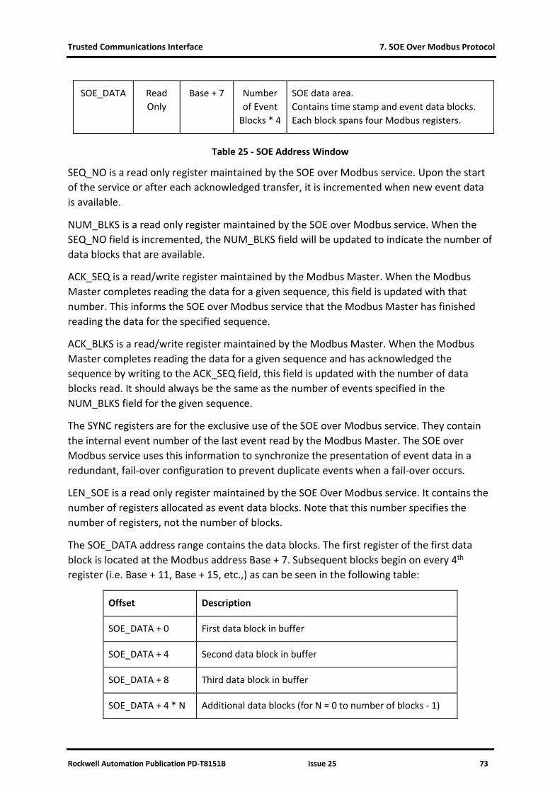
Trusted Communications Interface 7. SOE Over Modbus Protocol
Rockwell Automation Publication PD-T8151B Issue 25 73
SOE_DATA Read Only
Base + 7 Number of Event
Blocks * 4
SOE data area. Contains time stamp and event data blocks. Each block spans four Modbus registers.
Table 25 - SOE Address Window
SEQ_NO is a read only register maintained by the SOE over Modbus service. Upon the start of the service or after each acknowledged transfer, it is incremented when new event data is available.
NUM_BLKS is a read only register maintained by the SOE over Modbus service. When the SEQ_NO field is incremented, the NUM_BLKS field will be updated to indicate the number of data blocks that are available.
ACK_SEQ is a read/write register maintained by the Modbus Master. When the Modbus Master completes reading the data for a given sequence, this field is updated with that number. This informs the SOE over Modbus service that the Modbus Master has finished reading the data for the specified sequence.
ACK_BLKS is a read/write register maintained by the Modbus Master. When the Modbus Master completes reading the data for a given sequence and has acknowledged the sequence by writing to the ACK_SEQ field, this field is updated with the number of data blocks read. It should always be the same as the number of events specified in the NUM_BLKS field for the given sequence.
The SYNC registers are for the exclusive use of the SOE over Modbus service. They contain the internal event number of the last event read by the Modbus Master. The SOE over Modbus service uses this information to synchronize the presentation of event data in a redundant, fail-over configuration to prevent duplicate events when a fail-over occurs.
LEN_SOE is a read only register maintained by the SOE Over Modbus service. It contains the number of registers allocated as event data blocks. Note that this number specifies the number of registers, not the number of blocks.
The SOE_DATA address range contains the data blocks. The first register of the first data block is located at the Modbus address Base + 7. Subsequent blocks begin on every 4th register (i.e. Base + 11, Base + 15, etc.,) as can be seen in the following table:
Offset Description
SOE_DATA + 0 First data block in buffer
SOE_DATA + 4 Second data block in buffer
SOE_DATA + 8 Third data block in buffer
SOE_DATA + 4 * N Additional data blocks (for N = 0 to number of blocks - 1)

7. SOE Over Modbus Protocol Trusted Communications Interface
74 Issue 25 Rockwell Automation Publication PD-T8151B
Table 26 - SOE_DATA Event Block Locations
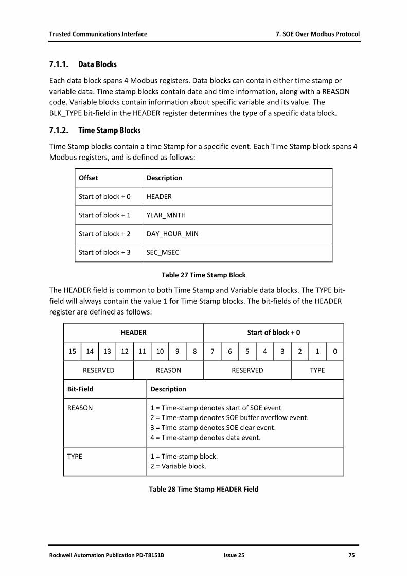
Trusted Communications Interface 7. SOE Over Modbus Protocol
Rockwell Automation Publication PD-T8151B Issue 25 75
7.1.1. Data Blocks
Each data block spans 4 Modbus registers. Data blocks can contain either time stamp or variable data. Time stamp blocks contain date and time information, along with a REASON code. Variable blocks contain information about specific variable and its value. The BLK_TYPE bit-field in the HEADER register determines the type of a specific data block.
7.1.2. Time Stamp Blocks
Time Stamp blocks contain a time Stamp for a specific event. Each Time Stamp block spans 4 Modbus registers, and is defined as follows:
Offset Description
Start of block + 0 HEADER
Start of block + 1 YEAR_MNTH
Start of block + 2 DAY_HOUR_MIN
Start of block + 3 SEC_MSEC
Table 27 Time Stamp Block
The HEADER field is common to both Time Stamp and Variable data blocks. The TYPE bit-field will always contain the value 1 for Time Stamp blocks. The bit-fields of the HEADER register are defined as follows:
HEADER Start of block + 0
15 14 13 12 11 10 9 8 7 6 5 4 3 2 1 0
RESERVED REASON RESERVED TYPE
Bit-Field Description
REASON 1 = Time-stamp denotes start of SOE event 2 = Time-stamp denotes SOE buffer overflow event. 3 = Time-stamp denotes SOE clear event. 4 = Time-stamp denotes data event.
TYPE 1 = Time-stamp block. 2 = Variable block.
Table 28 Time Stamp HEADER Field
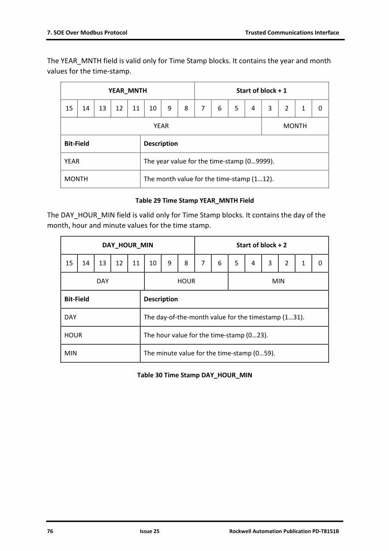
7. SOE Over Modbus Protocol Trusted Communications Interface
76 Issue 25 Rockwell Automation Publication PD-T8151B
The YEAR_MNTH field is valid only for Time Stamp blocks. It contains the year and month values for the time-stamp.
YEAR_MNTH Start of block + 1
15 14 13 12 11 10 9 8 7 6 5 4 3 2 1 0
YEAR MONTH
Bit-Field Description
YEAR The year value for the time-stamp (0…9999).
MONTH The month value for the time-stamp (1…12).
Table 29 Time Stamp YEAR_MNTH Field
The DAY_HOUR_MIN field is valid only for Time Stamp blocks. It contains the day of the month, hour and minute values for the time stamp.
DAY_HOUR_MIN Start of block + 2
15 14 13 12 11 10 9 8 7 6 5 4 3 2 1 0
DAY HOUR MIN
Bit-Field Description
DAY The day-of-the-month value for the timestamp (1…31).
HOUR The hour value for the time-stamp (0…23).
MIN The minute value for the time-stamp (0…59).
Table 30 Time Stamp DAY_HOUR_MIN

Trusted Communications Interface 7. SOE Over Modbus Protocol
Rockwell Automation Publication PD-T8151B Issue 25 77
The SEC_MSEC field is valid only for Time Stamp blocks. It contains the second and millisecond values for the time-stamp.
SEC_MSEC Start of block + 3
15 14 13 12 11 10 9 8 7 6 5 4 3 2 1 0
SEC MSEC
Bit-Field Description
SEC The second value for the time-stamp (0…59).
MSEC The milli-second value for the time-stamp (0…999).
Table 31 Time Stamp SEC_MSEC Field
7.2. Variable Blocks
Variable blocks contain information about a variable that has changed state. Each Variable block spans 4 Modbus registers, and is defined as follows:
Offset Description
Start of block + 0 HEADER
Start of block + 1 ADDRESS
Start of block + 2 VALUE
Start of block + 3 NOT_USED (always 0)
Table 32 Variable Data

7. SOE Over Modbus Protocol Trusted Communications Interface
78 Issue 25 Rockwell Automation Publication PD-T8151B
The HEADER field is common to both Time-stamp and Variable data blocks. The TYPE bit-field will always contain the value 2 for Variable blocks. The bit-fields of the HEADER register are defined as follows:
HEADER Start of block + 0
15 14 13 12 11 10 9 8 7 6 5 4 3 2 1 0
RESERVED REASON RESERVED TYPE
Bit-Field Description
REASON Not valid for Variable blocks.
TYPE 1 = Time-stamp block. 2 = Variable block.
Table 33 Variable HEADER Field
The ADDRESS field contains the Modbus address of the variable that has changed.
ADDRESS Start of block + 1
15 14 13 12 11 10 9 8 7 6 5 4 3 2 1 0
ADDRESS
Bit-Field Description
ADDRESS The Modbus address of the variable.
Table 34 Variable ADDRESS Field
The VALUE field contains the new value of the variable after the change. For Boolean type variables, the value will be limited to 0 or 1.
VALUE Start of block + 2
15 14 13 12 11 10 9 8 7 6 5 4 3 2 1 0
VALUE
Bit-Field Description
VALUE The new value of the variable.
Table 35 Variable VALUE Field
Trusted Communications Interface 7. SOE Over Modbus Protocol
Rockwell Automation Publication PD-T8151B Issue 25 79
7.3. Protocol Responsibilities
The goal of the SOE over Modbus protocol is to facilitate the transfer of buffered event data across a Modbus link. To that end, the protocol establishes well defined register locations as described above. In addition to the register definitions, the protocol also requires specific sequences of interaction between the Modbus Master (the “Master”) and the SOE over Modbus service (the “Service”).
7.4. SOE Over Modbus Service Responsibilities
The sequence begins in the IDLE state. The IDLE state is characterised by the SEQ_NO and ACK_SEQ being equal, and the NUM_BLKS and ACK_BLKS being equal. On startup, the service will ensure the registers are initialised to the IDLE state.
While in the IDLE state, the Service will wait until it receives one or more events. The events are encoded into the appropriate data blocks, with the first data block at the start of the SOE_DATA area. The Service will continue to receive events and place them sequentially in data blocks in the SOE_DATA until there are no more events in the queue, or the maximum number of data blocks has been reached.
The Service will then record the number of data blocks available in the SOE_DATA area in the NUM_BLKS register followed by incrementing the value of the SEQ_NO register. This marks the beginning of the XFER state.
While in the XFER state, the Service will ignore new events, keeping them on the queue until the next time the IDLE state is entered.
The Service will examine the SEQ_NO, ACK_SEQ, NUM_BLKS, and ACK_BLKS registers to determine when the XFER state has completed, and a new IDLE state has begun. The XFER state will be complete only when the SEQ_NO and ACK_SEQ are equal, and the NUM_BLKS and ACK_BLKS are equal.
7.5. Modbus Master Responsibilities
The Master will examine the SEQ_NO and ACK_SEQ registers to determine when the IDLE state is over and a new XFER state has begun. The XFER state will have begun only when the SEQ_NO and ACK_SEQ are not equal, and the NUM_BLKS and ACK_BLKS are not equal.
The Master will then read each of the blocks in the SOE_DATA area as specified in the NUM_BLKS register. The Master may do this one block at a time or in block groups, up to the limits imposed either by the size of the SOE_DATA area, or by the limitations of the MODBUS read command. The Master may also read all blocks in the SOE_DATA area, ignoring those that do not contain valid data for this sequence.

7. SOE Over Modbus Protocol Trusted Communications Interface
80 Issue 25 Rockwell Automation Publication PD-T8151B
Once the blocks have been read, the Master writes the value in NUM_BLKS to the ACK_BLKS register, then the value in SEQ_NO to the ACK_SEQ register. This will end the XFER state, and mark the beginning of the next IDLE state.
7.6. SOE_DATA Contents
The data blocks read from the SOE_DATA area will contain either Time stamp or Variable information. For each sequence, a Time stamp block with a REASON code of 4 (data event) will proceed the first Variable block. Subsequent Variable blocks will use the time stamp from the preceding Time stamp block. Note that it is possible to have a single Time stamp block followed by any number of Variable blocks. In such a case, all of the variables share the same time stamp. It is also possible to have a Time stamp block preceding each Variable block. In such a case, each variable is associated with a unique time stamp. Because a Time stamp block is present before the first Variable block of a sequence, it is possible for 2 Variable blocks transferred in different sequences to share a time stamp that was derived from 2 separate (but equal) Time stamp blocks.
There is no guarantee that the time stamps contained in subsequent Time stamp blocks will be in order.

Trusted Communications Interface 8. Specifications
Rockwell Automation Publication PD-T8151B Issue 25 81
8. Specifications
Backplane (IMB) Supply 20 Vdc to 32 Vdc
Field Supply N/A
Power Dissipation 10 W
Module Location T8100, T8300 I/O Module Slot
Isolation 50 V Basic Insulation, Module to Backplane Supply, Module to Diagnostic Serial Port
250 V Basic Insulation, Module to Rear Serial Ports, Module to Ethernet Ports, Serial Ports to Ethernet Ports, Between Serial Ports, Between Ethernet Ports
Fusing Not User Serviceable
Ports 2 Rear Serial Ports, RS-232/422/485
2 Rear Serial Ports, RS-422/485
2 Ethernet Ports, 10/100BaseT
1 Diagnostics Serial Port, RS-232
Baud Rates 1200 baud to 115200 baud
Communications Protocols
(See 3.1 Supported Protocols for further details)
Modbus RTU
Open Modbus TCP
Trusted Peer to Peer
Trusted Enhanced Peer to Peer
ICS2000
CP2000
SOE Buffer 4000 Events
Operating Temperature 0 °C to +60 °C (+32 °F to +140 °F)
Storage Temperature -25 °C to +70 °C (-13 °F to +158 °F)
Relative Humidity - Operating and Storage 10 % – 95 %, non-condensing

8. Specifications Trusted Communications Interface
82 Issue 25 Rockwell Automation Publication PD-T8151B
Environmental Specifications Refer to Document 552517
Dimensions
Height 266 mm (10.5 in)
Width 31 mm (1.2 in)
Depth 303 mm (12.0 in)
Weight 1.13 kg (2.49 lb)