tuning a stmtouch-based application - … · tuning a stmtouch-based application ... structure the...
TRANSCRIPT

October 2015 DocID024847 Rev 3 1/26
AN4316Application note
Tuning a STMTouch-based application
1 Introduction
This document is intended for touch sensing application designers and provides guidelines on how to tune their system. STM Studio tool is introduced and information is provided on how to use it in order to monitor the variables. A particular emphasis will be placed on providing a methodology to configure the STMTouch library parameters.
This document shows how to trim firmware parameters and adjust hardware components to optimize the performance of your application.
This document is not intended to replace product documentation and library user manual
All values given in this document are for guidance only. Please, refer to the related datasheet to get guaranteed values.
Note: STMicroelectronics is providing free STMTouch touch sensing firmware libraries which are available either as standalone packages (STM8L-TOUCH-LIB) or directly integrated into the corresponding STM32Cube package (STM32CubeL0, STM32CubeF0, …).
Table 1. Applicable products
Type Applicable products
MicrocontrollersSTM32F0 series, STM32F3 series, STM32L0 series, STM32L1 series, STM32L4 series, STM8L series, STM8AL series.
www.st.com
Contents AN4316
2/26 DocID024847 Rev 3
Contents
1 Introduction . . . . . . . . . . . . . . . . . . . . . . . . . . . . . . . . . . . . . . . . . . . . . . . . 1
2 STM Studio overview . . . . . . . . . . . . . . . . . . . . . . . . . . . . . . . . . . . . . . . . 5
3 Monitoring STMTouch driver variables using STM Studio . . . . . . . . . . 6
4 Tuning of the thresholds . . . . . . . . . . . . . . . . . . . . . . . . . . . . . . . . . . . . 11
4.1 Use of a standard test finger . . . . . . . . . . . . . . . . . . . . . . . . . . . . . . . . . . .11
4.2 Threshold definitions . . . . . . . . . . . . . . . . . . . . . . . . . . . . . . . . . . . . . . . . .11
4.2.1 Touchkeys thresholds . . . . . . . . . . . . . . . . . . . . . . . . . . . . . . . . . . . . . . 11
4.2.2 Linear and rotary touch sensors thresholds . . . . . . . . . . . . . . . . . . . . . . 14
4.2.3 Proximity . . . . . . . . . . . . . . . . . . . . . . . . . . . . . . . . . . . . . . . . . . . . . . . . 16
4.3 Debounce settings . . . . . . . . . . . . . . . . . . . . . . . . . . . . . . . . . . . . . . . . . . 17
5 Charge transfer period tuning . . . . . . . . . . . . . . . . . . . . . . . . . . . . . . . . 18
6 Hardware trimming . . . . . . . . . . . . . . . . . . . . . . . . . . . . . . . . . . . . . . . . . 20
6.1 Cs trimming . . . . . . . . . . . . . . . . . . . . . . . . . . . . . . . . . . . . . . . . . . . . . . . 20
6.2 Shield adjustment . . . . . . . . . . . . . . . . . . . . . . . . . . . . . . . . . . . . . . . . . . . 20
7 Performance comparison . . . . . . . . . . . . . . . . . . . . . . . . . . . . . . . . . . . . 22
8 Conclusion . . . . . . . . . . . . . . . . . . . . . . . . . . . . . . . . . . . . . . . . . . . . . . . . 23
Appendix A . . . . . . . . . . . . . . . . . . . . . . . . . . . . . . . . . . . . . . . . . . . . . . . . . . . . . . . 24
9 Revision history . . . . . . . . . . . . . . . . . . . . . . . . . . . . . . . . . . . . . . . . . . . 25

DocID024847 Rev 3 3/26
AN4316 List of tables
3
List of tables
Table 1. Applicable products . . . . . . . . . . . . . . . . . . . . . . . . . . . . . . . . . . . . . . . . . . . . . . . . . . . . . . . 1Table 2. Document revision history . . . . . . . . . . . . . . . . . . . . . . . . . . . . . . . . . . . . . . . . . . . . . . . . . 25

List of figures AN4316
4/26 DocID024847 Rev 3
List of figures
Figure 1. STM Studio variable selection window . . . . . . . . . . . . . . . . . . . . . . . . . . . . . . . . . . . . . . . . . 7Figure 2. VarViewers with variable name . . . . . . . . . . . . . . . . . . . . . . . . . . . . . . . . . . . . . . . . . . . . . . 8Figure 3. Data log setting. . . . . . . . . . . . . . . . . . . . . . . . . . . . . . . . . . . . . . . . . . . . . . . . . . . . . . . . . . 10Figure 4. Standard 8mm diameter finger . . . . . . . . . . . . . . . . . . . . . . . . . . . . . . . . . . . . . . . . . . . . . . 11Figure 5. Threshold position . . . . . . . . . . . . . . . . . . . . . . . . . . . . . . . . . . . . . . . . . . . . . . . . . . . . . . . 12Figure 6. Rotary sensor log . . . . . . . . . . . . . . . . . . . . . . . . . . . . . . . . . . . . . . . . . . . . . . . . . . . . . . . . 14Figure 7. Sensor log before balancing . . . . . . . . . . . . . . . . . . . . . . . . . . . . . . . . . . . . . . . . . . . . . . . . 15Figure 8. Debouncing example . . . . . . . . . . . . . . . . . . . . . . . . . . . . . . . . . . . . . . . . . . . . . . . . . . . . . 17Figure 9. Metallic coin probe . . . . . . . . . . . . . . . . . . . . . . . . . . . . . . . . . . . . . . . . . . . . . . . . . . . . . . . 18Figure 10. Ideal charge transfers . . . . . . . . . . . . . . . . . . . . . . . . . . . . . . . . . . . . . . . . . . . . . . . . . . . . . 19Figure 11. Non-ideal charge transfers . . . . . . . . . . . . . . . . . . . . . . . . . . . . . . . . . . . . . . . . . . . . . . . . . 19Figure 12. Active shield Cs trimming . . . . . . . . . . . . . . . . . . . . . . . . . . . . . . . . . . . . . . . . . . . . . . . . . . 20Figure 13. Active shield Rs trimming . . . . . . . . . . . . . . . . . . . . . . . . . . . . . . . . . . . . . . . . . . . . . . . . . . 21Figure 14. SNR computation . . . . . . . . . . . . . . . . . . . . . . . . . . . . . . . . . . . . . . . . . . . . . . . . . . . . . . . . 22Figure 15. Recommended standard finger . . . . . . . . . . . . . . . . . . . . . . . . . . . . . . . . . . . . . . . . . . . . . 24

DocID024847 Rev 3 5/26
AN4316 STM Studio overview
25
2 STM Studio overview
STM Studio is a free software tools that helps to debug and diagnose STM8 and STM32 applications while they are running by reading and displaying their variables in real-time.
Running on a PC, STM Studio interfaces with STM8 and STM32 MCUs via standard development tools, such as the low cost ST-LINK and RLink along with the high-end STM8 STice emulation system.
STM Studio is a non-intrusive tool, preserving the real-time behavior of applications.
STM Studio perfectly complements traditional debugging tools to fine tune applications. It is well suited for debugging applications which cannot be stopped, such as motor control applications.
Different graphic views are available to match the needs of debugging and diagnosis or to demonstrate application behavior. This tool works with STM8 microcontrollers through SWIM (single wire interface module) and with STM32 microcontrollers through JTAG or SWD (serial wire debug) interface.
It is a graphical user interface for probing and visualizing in real time application's variables while it is running. It is designed to run on a computer with Microsoft® Windows operating systems.
Please refer to STM Studio release notes to know the host PC system requirements and supported hardware.
For advanced information on how to use STM Studio, please refer to its user manual (UM1025; Getting started with STM Studio).

Monitoring STMTouch driver variables using STM Studio AN4316
6/26 DocID024847 Rev 3
3 Monitoring STMTouch driver variables using STM Studio
The main parameters to trim a touch sensing application are:
The channel references, the “Ref” element of an array of TSL_ChannelData_T structure
The channel deltas, the “Delta” element of an array of TSL_ChannelData_T structure
The object states, the “StateId” element of an array of TSL_TouchKeyData_T structure or a TSL_LinRotData_T structure
This list is not exhaustive and will depends on the application.
The following procedure provides an easy way to import such variables:
1. Open STM Studio
2. Right-click in the “Display Variables” tab and select “Import...” or select the “File/Import Variables” menu
3. In the “Import variables from executable” window,
a) select your application Elf file (.elf, .out or .axf) Through the “Executable file” field using the browse button
b) check the “Expand table elements” check-box
c) Select the “Store executable path relatively to the user setting file” check box to use relative path.
d) enter “Ref” in the “Show symbol containing...” text box
e) select “Add variables to the display variables table” in the Variables list box
f) select the “.Ref” ended variables and click on “Import” button or Ctrl+Click to operate an uncontinuous multi-selection
g) repeat step d) and f) with Delta
h) repeat step d) and f) with StateId
i) click “Close” button

DocID024847 Rev 3 7/26
AN4316 Monitoring STMTouch driver variables using STM Studio
25
Figure 1. STM Studio variable selection window

Monitoring STMTouch driver variables using STM Studio AN4316
8/26 DocID024847 Rev 3
Once imported, the variables must be assigned to Viewer in order to be displayed:
1. In the “Display Variables settings” table, select all the “Ref” items (you can use Shift+Click to operate a continuous multi-selection or Ctrl+Click to operate an uncontinuous multi-selection)
2. Right-click in the table and select “Send To → VarViewer1”, or drag them directly to the right viewer.
3. In the “Viewers settings” window dock, right-click in the greyed part and select “New VarViewer”. A “VarViewer2” tab appears.
4. Repeat step 4, 5 and 6 for the “Delta” items
5. Repeat step 4 and 5 for the “StateId” items
To ease the navigation, you can rename the VarViewer windows with the name of the monitored variables by right click and rename.
Variables can be displayed as a curve, as a bar graph or in a table. Table display is recommended for variables with very slow variation. Curve and bar graph suit for variables with quick variation.
Figure 2. VarViewers with variable name
DocID024847 Rev 3 9/26
AN4316 Monitoring STMTouch driver variables using STM Studio
25
Then, adjust the value range for each varviewer:
The Delta depends on the application sensitivity and can be positive or negative
The State varies from 0 to 19, for value meanings refer to TSL_StateId_enum_T in tsl_types.h.
The reference depends on Cx/Cs
At this point, you have to connect the PC to your application with the selected binary code downloaded in the microcontroller, through a USB cable and the appropriate hardware tool (such as a ST-Link).
To start monitoring, click on the green arrow or select the “Run/Start” menu.

Monitoring STMTouch driver variables using STM Studio AN4316
10/26 DocID024847 Rev 3
The data can be stored in a file:
1. Open “Options” and “Acquisition Settings” window.
2. Select “Log to file” check box and set you log file path.
Figure 3. Data log setting
DocID024847 Rev 3 11/26
AN4316 Tuning of the thresholds
25
4 Tuning of the thresholds
This section provides recommendations on how to select reliable thresholds. Depending on application use cases, some recommendations will have to be adapted.
Capacitive touch sensing applications are sensitive to earth coupling. The parameter tunning must be done in the same environment as the final application. The hardware tool connected to the application may change the earth coupling. This is especially true for example in battery power applications. ST is providing a galvanic insulated hardware tool (ST-Link/ISOL) to minimize this effect.
4.1 Use of a standard test finger
In order to build an application working with the widest range of people finger characteristics, we propose to use a standard test finger which will give a worst case but also will allow to repeat the test without human dependency, such as finger size, pressure and contact area, skin conductivity, etc... To perform repeatable test, it is recommended to use an electrically conductive pen-shape tool with a flat rubber end. The flat end made of conductive rubber, allows to touch the touchkey with a constant contact surface.
The operator performing the validation will take care to center the contact area on the touchkey.
Additionally, it makes sense to plan a final validation with a panel of users.
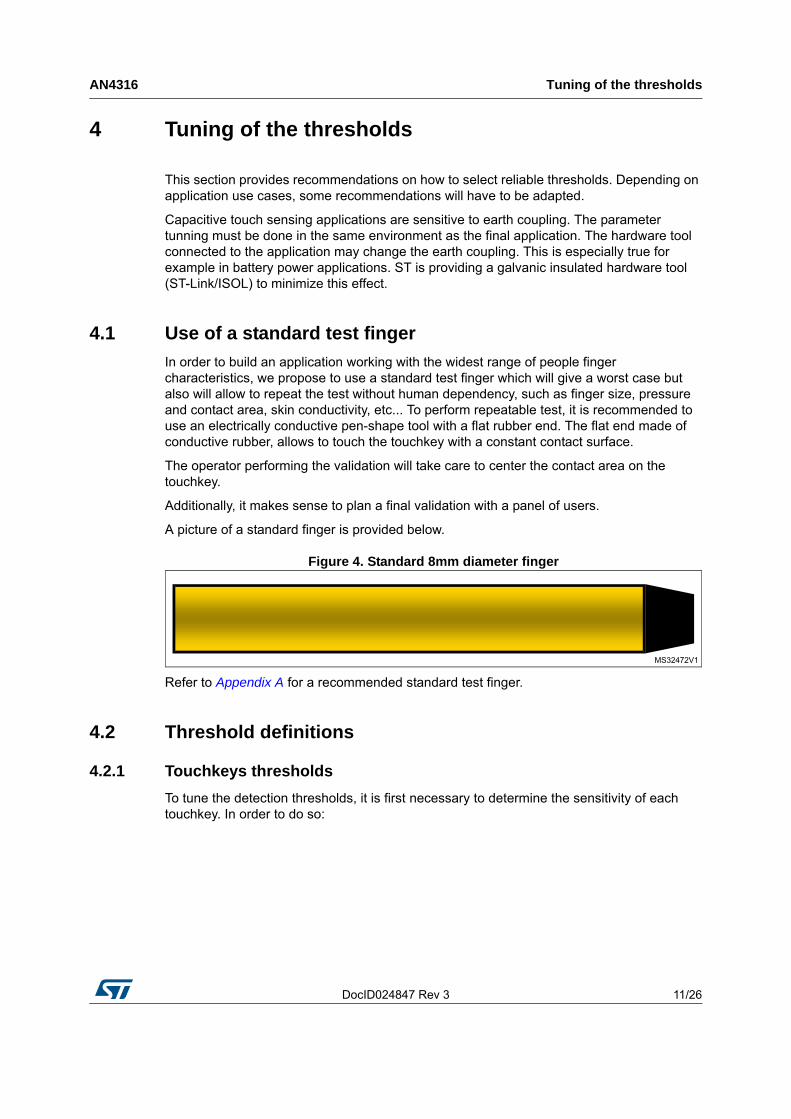
A picture of a standard finger is provided below.
Figure 4. Standard 8mm diameter finger
Refer to Appendix A for a recommended standard test finger.
4.2 Threshold definitions
4.2.1 Touchkeys thresholds
To tune the detection thresholds, it is first necessary to determine the sensitivity of each touchkey. In order to do so:
Tuning of the thresholds AN4316
12/26 DocID024847 Rev 3
1. Connect the final hardware to a PC through the ST-Link and power the application
2. Download the firmware which will be used in the final application with the final parameters of the STMTouch driver.The default detection thresholds can be set to a low value but keeping it higher than the noise Level.
3. Launch STM Studio and configure it as explained in Section 2: STM Studio overview on page 5.
4. Use the standard finger as described in Section 4.1: Use of a standard test finger on page 11.
5. Touch a touchkey and move the finger in order to find the maximum delta and write down this value, then repeat it for each touchkey. If around the maximum delta there is still significant jittering on the measure, then compute the average and use it as baseline.
These values will be the baseline of all the thresholds. If a significant variation exists between the baseline of the application touchkeys, it is recommended to set a specific threshold for each touchkey.
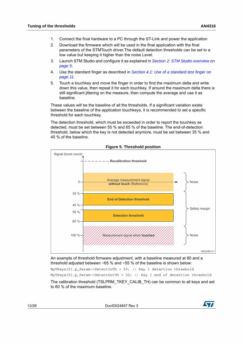
The detection threshold, which must be exceeded in order to report the touchkey as detected, must be set between 55 % and 65 % of the baseline. The end-of-detection threshold, below which the key is not detected anymore, must be set between 35 % and 45 % of the baseline.
Figure 5. Threshold position
An example of threshold firmware adjustment, with a baseline measured at 80 and a threshold adjusted between ~65 % and ~55 % of the baseline is shown below:
MyTKeys[0].p_Param->DetectInTh = 50; // Key 1 detection threshold
MyTKeys[0].p_Param->DetectOutTh = 30; // Key 1 end of detection threshold
The calibration threshold (TSLPRM_TKEY_CALIB_TH) can be common to all keys and set to 60 % of the maximum baseline.

DocID024847 Rev 3 13/26
AN4316 Tuning of the thresholds
25
If one of these thresholds must be greater than 255, the TSLPRM_COEFF_TH must be set in order to bring the value in the correct range [0;255]. This is obtained by dividing all thresholds, except the calibration threshold, by 2 to the power of TSLPRM_COEFF_TH. In that case, the divided coefficients values (except for the calibration threshold) are the values that need to be configured in the firmware. A compensation factor of 2 to the power of TSLPRM_COEFF_TH will then be applied to all coefficients (except the calibration threshold) by the firmware.

Tuning of the thresholds AN4316
14/26 DocID024847 Rev 3
4.2.2 Linear and rotary touch sensors thresholds
For such type of sensors, the approach is different in the sense that these sensors are composed of several channels. The standard test finger must be moved along the whole sensor and a log of the delta must be recorded using STM Studio.
Detection thresholds adjustment
A rotary sensor log example is provided below:
Figure 6. Rotary sensor log
The worst case delta as shown in the figure above must be considered as the baseline to compute the threshold for this sensor. This threshold must be reached in order to trig the computation of the position and to report a detection on this sensor.
The same ratio used for a touchkey can be applied to this baseline, so between 65 % and 55 % to enter in detection and between 35 % and 45 % to stop reporting a detection.

DocID024847 Rev 3 15/26
AN4316 Tuning of the thresholds
25
Balancing between channels
While a significant difference of sensitivity appear on the channels, the STMTouch driver provide a way to balance the delta in order to minimize the error on the position computation.
The sensitivity is determined with the maximum delta on each channel.
The figure below shows a log from a rotary sensor with an excessive difference of sensitivity.
Figure 7. Sensor log before balancing
To get well-balanced channels, a coefficient will be applied to each channel delta. This coefficient is the ratio between the maximum deltas of each channel. The reference channel is the one with the highest delta (A for channel 1), the others channels have their maximum delta in B for channel 0, and C for channel 2. The coefficient of channel 0 will be set to A/B and the one of channel 2 set to A/C. Channel 1 is not changed and gets its coefficient at 1.
These coefficients must be multiplied by 255 as they are used as a fraction of 255.
For instance:
A/B = 1.75 the coefficient is 488 = 0x1C0
A/C = 3 the coefficient is 768 = 0x300 then the code will be:
CONST uint16_t MyLinRot0_DeltaCoeff[LINROT_CHANNELS] =
{
0x1C0, 0x100, 0x300,// CH0, CH1, CH2
};

Tuning of the thresholds AN4316
16/26 DocID024847 Rev 3
MyLinRot0_DeltaCoeff will be pointed by the p_DeltaCoeff item in the declaration of the TSL_LinRot_T or TSL_LinRotB_T structure.
CONST TSL_LinRotB_T MyLinRots[TSLPRM_TOTAL_LNRTS] =
{
{
&MyLinRots_Data[0],
&MyLinRots_Params[0],
&MyChannels_Data[CHANNEL_16_DEST],
(TSL_tNb_T)LINROT_CHANNELS,
MyLinRot0_DeltaCoeff,
(TSL_tsignPosition_T *)TSL_POSOFF_3CH_LIN_INTERLACED,
(TSL_tIndex_T) TSL_SCTCOMP_3CH_LIN_INTERLACED,
(TSL_tIndex_T) TSL_POSCORR_3CH_LIN_INTERLACED
}
};
4.2.3 Proximity
To define the proximity thresholds, the designer must consider the noise sensitivity and the expected detection distance, but also the minimum surface to detect.

DocID024847 Rev 3 17/26
AN4316 Tuning of the thresholds
25
4.3 Debounce settings
In order to improve the robustness of the application, the STMTouch driver provides the debounce feature. To validate a touch detection, the delta must have exceeded the threshold during a certain number of consecutive samples as shown in Figure 8. This is to avoid a false-detection due to a noise peak.
Figure 8. Debouncing example
Due to the use of a down-counter, the DEBOUNCE preprocessor constant must be set to n-1 while n consecutive sample must be measured below the detection threshold before triggering a detection.
#define TSLPRM_DEBOUNCE_DETECT (2) //3 consecutive samples needed to enter in Detection.
The debounce feature is configurable for each state transition:
TSLPRM_DEBOUNCE_PROX: while switching from release state to proximity state
TSLPRM_DEBOUNCE_DETECT: while switching from release state or proximity to touch detection state
TSLPRM_DEBOUNCE_RELEASE: while switching from touch or proximity state to release state
TSLPRM_DEBOUNCE_CALIB: while switching from release state to calibration state (compute again the reference)
TSLPRM_DEBOUNCE_ERROR: while switching from any state to error state

Charge transfer period tuning AN4316
18/26 DocID024847 Rev 3
5 Charge transfer period tuning
The acquisition is based on the measurement of the sensor channel capacitance (or a set of sensors in the case of linear and rotary sensors). The more charged this sensor capacitance, the more accurate the measure and the better the noise immunity.
To ensure that the capacitance is correctly charged, it is necessary to monitor the pin connected to the sensor plate or through a metallic coin put on the sensor.
Figure 9. Metallic coin probe
The signal must show a square wave which indicates a fully loaded capacitance.
Figure 10 shows an example of ideal charge transfers and Figure 11 a non-ideal ones.

DocID024847 Rev 3 19/26
AN4316 Charge transfer period tuning
25
Figure 10. Ideal charge transfers
Figure 11. Non-ideal charge transfers
In case of an uncompleted charge, the user must increase the charge transfer period.
Depending on the product and type of acquisition, different adjustments are necessary. The involved parameters are in the MCU PARAMETERS section of the tsl_conf_stmxxxx.h file:
For STM32F0, STM32F3 and STM32L0 products embedding the TSC peripheral, the trimming is done by increasing TSLPRM_TSC_CTPH for the charge period and/or TSLPRM_TSC_CTPL for the transfer period, and optionally TSLPRM_TSC_PGPSC to divide the pulse generator frequency by a power of 2.
For STM32L1 product, the charge transfer period is set through TSLPRM_CT_PERIOD and TSLPRM_TIMER_FREQ parameters.
For STM8L and STM8AL products, the delay is expressed in number of NOP instructions, executed in one cycle at the CPU frequency (max 16 MHz so in 62.5 ns). Two parameters are provided: one for the charge period TSLPRM_DELAY_CHARGE and one for the transfer period TSLPRM_DELAY_TRANSFER.
Please refer to the product related firmware documentation for more details.

Hardware trimming AN4316
20/26 DocID024847 Rev 3
6 Hardware trimming
6.1 Cs trimming
The Cs capacitance is a key parameter for sensitivity. For touchkey sensors, the Cs value is usually comprised between 8.7nF to 22nF. For linear and rotary touch sensors, the value is usually comprised between 47nF and 100nF. These values are given as reference for an electrode fitting a human finger tip size across a few millimeters dielectric panel.
The signal delta for a touchkey is usually above 20 while it’s around 100 for linear and rotary touch sensors. These values are given for a normalized test finger.
6.2 Shield adjustment
The efficiency of the shield depends on the waveforms matching between the shielded channel and the shield burst pulses. The parameters to adapt the shield waveform are Cs and Rs. These parameters adjustment is performed in 2 steps:
1. Active shield Cs trimming
The burst envelop of the channels belonging to a same bank should end at the same voltage level (VIH):
Figure 12. Active shield Cs trimming

DocID024847 Rev 3 21/26
AN4316 Hardware trimming
25
2. Active shield Rs trimming
Rs should be trimmed to ensure shield capacitance is fully charged.
Figure 13. Active shield Rs trimming

Performance comparison AN4316
22/26 DocID024847 Rev 3
7 Performance comparison
In order to compare the performance of a whole touch sensing application, the usual parameter is the Signal to Noise Ratio, well-known as SNR. But each company, each team and even each engineer as its own method to compute it.
Here below we provide a way to compute it, but the designer must keep in mind that to get correct results, he must compare apples to apples. So the test conditions and the method of computation must be under control and reproductible else it is meaningless to compare two results.
In the above equation:
“Signal” is the average of the delta measurements during a touch
“Noise” is the amplitude (delta max - delta min) without touch.
Figure 14. SNR computation
In order to make meaningful comparisons, the various SNR measurements must be performed under similar test conditions.
The following parameters affect the results of the SNR:
hardware application i.e. layout, panel (dielectric, thickness, glue, ...), capacitance value and quality, etc...
firmware application i.e. acquisition configuration (frequency, reference, ..), threshold settings, etc...
test conditions i.e. object used to touch (standard test finger or genuine finger), way the panel is touched (pressure, slope, ...), applied noise if any, etc...
SNR SignalNoise------------------=

DocID024847 Rev 3 23/26
AN4316 Conclusion
25
8 Conclusion
In order to get the best performance for his STMTouch-based application, the designer must tune it correctly. STMicroelectronics provides STM Studio, a free and easy tool to help performing this task. It is important to have the thresholds and the debounce values set according to the application environment. To get the best performance, the charge transfer must be operated completely.
If you need to compare performances, keep in mind you must compare apples to apples and this can only be done by performing your own tests according to your application requirements.

AN4316
24/26 DocID024847 Rev 3
Appendix A
Figure 15. Recommended standard finger

DocID024847 Rev 3 25/26
AN4316 Revision history
25
9 Revision history
Table 2. Document revision history
Date Revision Changes
04-Mar-2014 1 Initial release.
11-Jun-2014 2 Added support for STM32L0 series and STM8AL series.
15-Oct-2015 3 Added support for STM32L4 series.

AN4316
26/26 DocID024847 Rev 3
Please Read Carefully:
Information in this document is provided solely in connection with ST products. STMicroelectronics NV and its subsidiaries (“ST”) reserve the right to make changes, corrections, modifications or improvements, to this document, and the products and services described herein at any time, without notice.
All ST products are sold pursuant to ST’s terms and conditions of sale.
Purchasers are solely responsible for the choice, selection and use of the ST products and services described herein, and ST assumes no liability whatsoever relating to the choice, selection or use of the ST products and services described herein.
No license, express or implied, by estoppel or otherwise, to any intellectual property rights is granted under this document. If any part of this document refers to any third party products or services it shall not be deemed a license grant by ST for the use of such third party products or services, or any intellectual property contained therein or considered as a warranty covering the use in any manner whatsoever of such third party products or services or any intellectual property contained therein.
UNLESS OTHERWISE SET FORTH IN ST’S TERMS AND CONDITIONS OF SALE ST DISCLAIMS ANY EXPRESS OR IMPLIED WARRANTY WITH RESPECT TO THE USE AND/OR SALE OF ST PRODUCTS INCLUDING WITHOUT LIMITATION IMPLIED WARRANTIES OF MERCHANTABILITY, FITNESS FOR A PARTICULAR PURPOSE (AND THEIR EQUIVALENTS UNDER THE LAWS OF ANY JURISDICTION), OR INFRINGEMENT OF ANY PATENT, COPYRIGHT OR OTHER INTELLECTUAL PROPERTY RIGHT.
ST PRODUCTS ARE NOT DESIGNED OR AUTHORIZED FOR USE IN: (A) SAFETY CRITICAL APPLICATIONS SUCH AS LIFE SUPPORTING, ACTIVE IMPLANTED DEVICES OR SYSTEMS WITH PRODUCT FUNCTIONAL SAFETY REQUIREMENTS; (B) AERONAUTIC APPLICATIONS; (C) AUTOMOTIVE APPLICATIONS OR ENVIRONMENTS, AND/OR (D) AEROSPACE APPLICATIONS OR ENVIRONMENTS. WHERE ST PRODUCTS ARE NOT DESIGNED FOR SUCH USE, THE PURCHASER SHALL USE PRODUCTS AT PURCHASER’S SOLE RISK, EVEN IF ST HAS BEEN INFORMED IN WRITING OF SUCH USAGE, UNLESS A PRODUCT IS EXPRESSLY DESIGNATED BY ST AS BEING INTENDED FOR “AUTOMOTIVE, AUTOMOTIVE SAFETY OR MEDICAL” INDUSTRY DOMAINS ACCORDING TO ST PRODUCT DESIGN SPECIFICATIONS. PRODUCTS FORMALLY ESCC, QML OR JAN QUALIFIED ARE DEEMED SUITABLE FOR USE IN AEROSPACE BY THE CORRESPONDING GOVERNMENTAL AGENCY.
Resale of ST products with provisions different from the statements and/or technical features set forth in this document shall immediately void any warranty granted by ST for the ST product or service described herein and shall not create or extend in any manner whatsoever, any liability of ST.
ST and the ST logo are trademarks or registered trademarks of ST in various countries.Information in this document supersedes and replaces all information previously supplied.
The ST logo is a registered trademark of STMicroelectronics. All other names are the property of their respective owners.
© 2015 STMicroelectronics - All rights reserved
STMicroelectronics group of companies
Australia - Belgium - Brazil - Canada - China - Czech Republic - Finland - France - Germany - Hong Kong - India - Israel - Italy - Japan - Malaysia - Malta - Morocco - Philippines - Singapore - Spain - Sweden - Switzerland - United Kingdom - United States of America
www.st.com