turbine inlet cooling 4turbineinletcooling.org/news/ticdoc_nov04.pdf · turbine inlet cooling ........
TRANSCRIPT
An Introduction to Turbine Inlet Cooling ...................... 4
A Perspective on the U.S. Electric Power Industry ..................... 6
Evaporative Cooling Technologies for Turbine Inlet Cooling .................10
Chiller Technologies for Turbine Inlet Cooling .................... 12
Thermal Energy Storage Technologies for Turbine Inlet Cooling ................................ 15
Hybrid Systems & LNG for Turbine Inlet Cooling (TIC) ............ 19
Turbine Inlet Cooling (TIC) Installation Success Stories ............ 21
Up to 35% Output Gains
Improved Heat Rate
Reduced Emissions
Improved Power Plant Life Cycle Cost
Average ROI – 2-5 years
Add Thermal Energy Storage for even more operational flexibility, and improved financial performance
+35%
-60%
+35%
-60%
Learn more at www.stellar-energy.net
Turbine Inlet Air ChillingThe Power Enhancement that Boosts Output,
Efficiency & Operational Flexibility
Stellar_TIAC_Ad_8.5x11_4c_ƒ.indd 1 7/31/15 4:24 PM
COOL YOUR JETS
4
Appeared in December 2003 Energy-Tech Magazine
What is TIC?TIC is cooling of the air before
it enters the compressor that supplies high-pressure air to the combustion cham-ber from which hot air at high pressure enters the combustion turbine. TIC is also called by many other names, includ-ing combustion turbine inlet air cooling (CTIAC), turbine inlet air cooling (TIAC), combustion turbine air cooling (CTAC), and gas turbine inlet air cooling (GTIAC).
Why Cool Turbine Inlet Air? The primary reason TIC is used is to
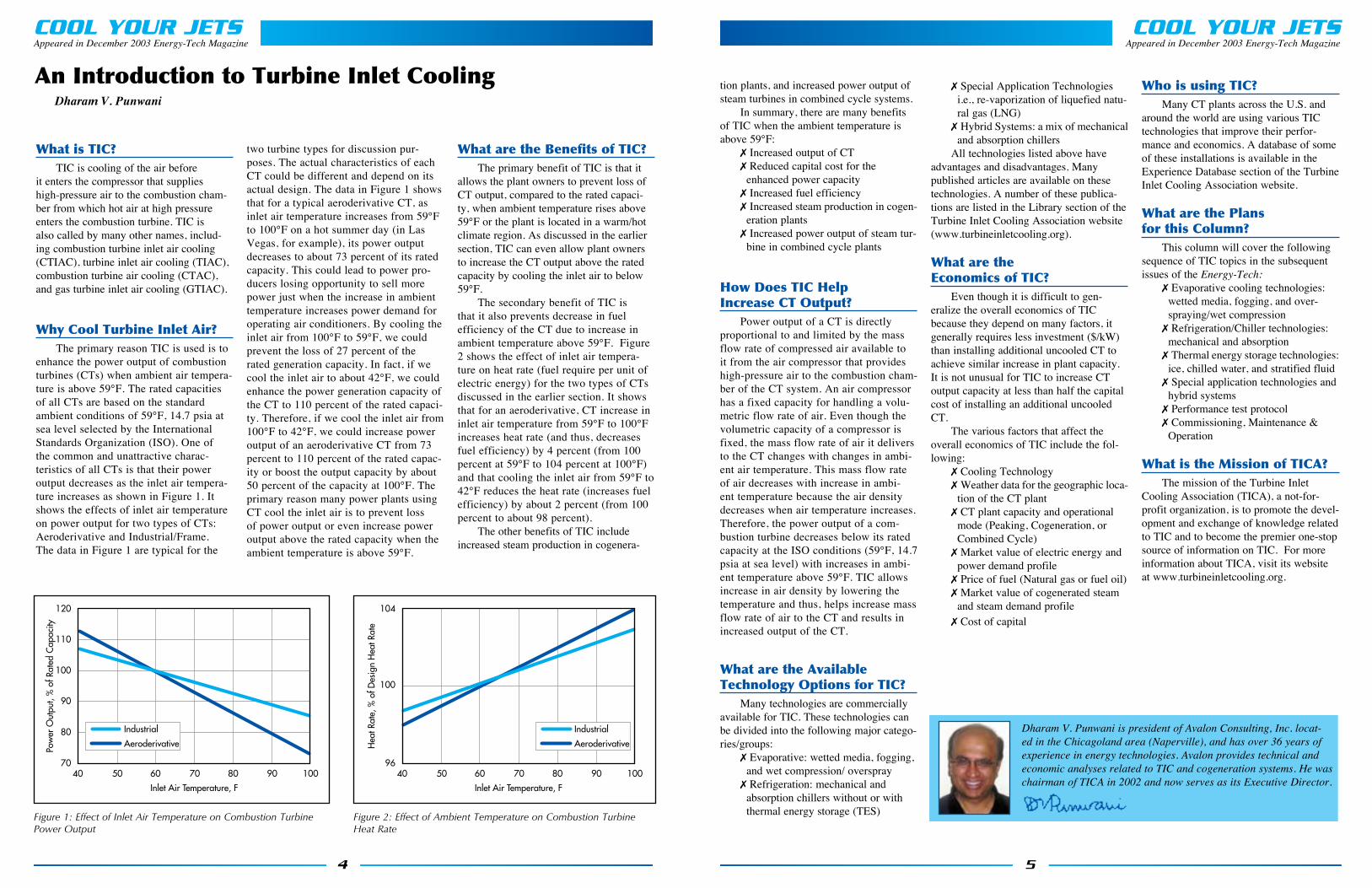
enhance the power output of combustion turbines (CTs) when ambient air tempera-ture is above 59°F. The rated capacities of all CTs are based on the standard ambient conditions of 59°F, 14.7 psia at sea level selected by the International Standards Organization (ISO). One of the common and unattractive charac-teristics of all CTs is that their power output decreases as the inlet air tempera-ture increases as shown in Figure 1. It shows the effects of inlet air temperature on power output for two types of CTs: Aeroderivative and Industrial/Frame. The data in Figure 1 are typical for the
two turbine types for discussion pur-poses. The actual characteristics of each CT could be different and depend on its actual design. The data in Figure 1 shows that for a typical aeroderivative CT, as inlet air temperature increases from 59°F to 100°F on a hot summer day (in Las Vegas, for example), its power output decreases to about 73 percent of its rated capacity. This could lead to power pro-ducers losing opportunity to sell more power just when the increase in ambient temperature increases power demand for operating air conditioners. By cooling the inlet air from 100°F to 59°F, we could prevent the loss of 27 percent of the rated generation capacity. In fact, if we cool the inlet air to about 42°F, we could enhance the power generation capacity of the CT to 110 percent of the rated capaci-ty. Therefore, if we cool the inlet air from 100°F to 42°F, we could increase power output of an aeroderivative CT from 73 percent to 110 percent of the rated capac-ity or boost the output capacity by about 50 percent of the capacity at 100°F. The primary reason many power plants using CT cool the inlet air is to prevent loss of power output or even increase power output above the rated capacity when the ambient temperature is above 59°F.
What are the Benefits of TIC?The primary benefit of TIC is that it
allows the plant owners to prevent loss of CT output, compared to the rated capaci-ty, when ambient temperature rises above 59°F or the plant is located in a warm/hot climate region. As discussed in the earlier section, TIC can even allow plant owners to increase the CT output above the rated capacity by cooling the inlet air to below 59°F.
The secondary benefit of TIC is that it also prevents decrease in fuel efficiency of the CT due to increase in ambient temperature above 59°F. Figure 2 shows the effect of inlet air tempera-ture on heat rate (fuel require per unit of electric energy) for the two types of CTs discussed in the earlier section. It shows that for an aeroderivative, CT increase in inlet air temperature from 59°F to 100°F increases heat rate (and thus, decreases fuel efficiency) by 4 percent (from 100 percent at 59°F to 104 percent at 100°F) and that cooling the inlet air from 59°F to 42°F reduces the heat rate (increases fuel efficiency) by about 2 percent (from 100 percent to about 98 percent).
The other benefits of TIC include increased steam production in cogenera-
An Introduction to Turbine Inlet CoolingDharam V. Punwani
120
110
90
80
7040 50 60 70 80 90 100
100
Pow
er O
utpu
t, %
of R
ated
Cap
acity
Inlet Air Temperature, F
Industrial
Aeroderivative
104
9640 50 60 70 80 90 100
100
Hea
t Rat
e, %
of D
esig
n H
eat R
ate
Inlet Air Temperature, F
Industrial
Aeroderivative
Figure 1: Effect of Inlet Air Temperature on Combustion Turbine Power Output
Figure 2: Effect of Ambient Temperature on Combustion Turbine Heat Rate
COOL YOUR JETS
5
Appeared in December 2003 Energy-Tech Magazine
tion plants, and increased power output of steam turbines in combined cycle systems.
In summary, there are many benefits of TIC when the ambient temperature is above 59°F:
7 Increased output of CT7 Reduced capital cost for the
enhanced power capacity7 Increased fuel efficiency7 Increased steam production in cogen-
eration plants7 Increased power output of steam tur-
bine in combined cycle plants
How Does TIC Help Increase CT Output?
Power output of a CT is directly proportional to and limited by the mass flow rate of compressed air available to it from the air compressor that provides high-pressure air to the combustion cham-ber of the CT system. An air compressor has a fixed capacity for handling a volu-metric flow rate of air. Even though the volumetric capacity of a compressor is fixed, the mass flow rate of air it delivers to the CT changes with changes in ambi-ent air temperature. This mass flow rate of air decreases with increase in ambi-ent temperature because the air density decreases when air temperature increases. Therefore, the power output of a com-bustion turbine decreases below its rated capacity at the ISO conditions (59°F, 14.7 psia at sea level) with increases in ambi-ent temperature above 59°F. TIC allows increase in air density by lowering the temperature and thus, helps increase mass flow rate of air to the CT and results in increased output of the CT.
What are the Available Technology Options for TIC?
Many technologies are commercially available for TIC. These technologies can be divided into the following major catego-ries/groups:
7 Evaporative: wetted media, fogging, and wet compression/ overspray
7 Refrigeration: mechanical and absorption chillers without or with thermal energy storage (TES)
7 Special Application Technologies i.e., re-vaporization of liquefied natu-ral gas (LNG)
7 Hybrid Systems: a mix of mechanical and absorption chillers
All technologies listed above have advantages and disadvantages. Many published articles are available on these technologies. A number of these publica-tions are listed in the Library section of the Turbine Inlet Cooling Association website (www.turbineinletcooling.org).
What are the Economics of TIC?
Even though it is difficult to gen-eralize the overall economics of TIC because they depend on many factors, it generally requires less investment ($/kW) than installing additional uncooled CT to achieve similar increase in plant capacity. It is not unusual for TIC to increase CT output capacity at less than half the capital cost of installing an additional uncooled CT.
The various factors that affect the overall economics of TIC include the fol-lowing:
7 Cooling Technology7 Weather data for the geographic loca-
tion of the CT plant7 CT plant capacity and operational
mode (Peaking, Cogeneration, or Combined Cycle)
7 Market value of electric energy and power demand profile
7 Price of fuel (Natural gas or fuel oil)7 Market value of cogenerated steam
and steam demand profile7 Cost of capital
Who is using TIC?Many CT plants across the U.S. and
around the world are using various TIC technologies that improve their perfor-mance and economics. A database of some of these installations is available in the Experience Database section of the Turbine Inlet Cooling Association website.
What are the Plans for this Column?
This column will cover the following sequence of TIC topics in the subsequent issues of the Energy-Tech:
7 Evaporative cooling technologies: wetted media, fogging, and over-spraying/wet compression
7 Refrigeration/Chiller technologies: mechanical and absorption
7 Thermal energy storage technologies: ice, chilled water, and stratified fluid
7 Special application technologies and hybrid systems
7 Performance test protocol7 Commissioning, Maintenance &
Operation
What is the Mission of TICA?The mission of the Turbine Inlet
Cooling Association (TICA), a not-for-profit organization, is to promote the devel-opment and exchange of knowledge related to TIC and to become the premier one-stop source of information on TIC. For more information about TICA, visit its website at www.turbineinletcooling.org.
Dharam V. Punwani is president of Avalon Consulting, Inc. locat-ed in the Chicagoland area (Naperville), and has over 36 years of experience in energy technologies. Avalon provides technical and economic analyses related to TIC and cogeneration systems. He was chairman of TICA in 2002 and now serves as its Executive Director.

power generation increases during summer (Figure 3). We all have seen the prices of natural gas peak much higher than ever before, while the average price of natural gas also seems to settle at a higher level than before (Figure 4). U.S. production of natural gas is not sufficient to meet demand; we now must import LNG to supplement it. Whether the combustion tur-bines use natural gas or oil, it is imperative that we not continue to operate our power systems at low efficiencies, particularly when much of the fuel source originates in an unstable and hostile region of the world.
SolutionsWe need a multi-faceted approach
for solving the problems within the power industry. This approach should include the following components:
7 Modernizing grid infrastructure7 Demand side management7 Distributed generation 7 Power augmentationWe cannot afford to continue with the
antiquated grid infrastructure - it must be modernized. Without it, all other approach-es for improving grid reliability will never be adequate. Modernizing grid infrastruc-ture is going to require a hefty budget from industry and government. It is not a near-term solution; it will require signifi-cant time. Nonetheless, improving the grid infrastructure alone will not improve grid reliability.
We should bring demand side man-agement back to the forefront. We should explore with more vigor the ways to shift power usage from day to night. It is time for the concept of thermal energy storage
(TES) to garner some serious consider-ation from the electricity demand side. TES allows electricity users to shift power demand from day to night; yet inexplica-bly it is not a serious part of the demand side management dialog today. Of course, we should continue to develop more energy-efficient light bulbs and refrigera-tion systems, etc. However, demand side management alone does not completely bridge the gap between power supply and demand.
Distributed generation can reduce load on the grid and therefore help improve grid reliability. The U.S. Combined Heat and Power Association (USCHPA) is making commendable efforts for disseminating information about the benefits of distrib-uted generation including combined heat and power. The USCHPA is a private, non-profit association, formed in 1999 to promote the merits of CHP and to achieve public policy support. It is attempting to create a regulatory, institutional, and market environment that fosters the use of clean, efficient CHP as a major source of electric power and thermal energy in the U.S. The goal of the USCHPA is to increase CHP generation capacity in the U.S. from 46 GW in 1998, to 92 GW by 2010. The traditional capital cost required for CHP systems is usually higher than that for centralized generation. New packaged CHP systems are under development with industry and government funding; these systems are energy efficient, will help improve grid reliability, and will conserve fuel resources.
Of these four solutions, Power Augmentation could have the biggest
potential impact in the immediate term. Power augmentation is an approach that allows combustion turbine (CT) power plants to continue to produce their rated power capacities—or more than the rated capacities— especially during hot weather conditions. Turbine Inlet Cooling (TIC) has been successfully used at many power plants across the world for power aug-mentation. While the TIC technologies in use today are at least 20 years old, power industry executives and planners remain alarmingly uneducated on this proven option. TIC increases energy efficiencies of CT power plants, is a well-proven technology, and serves as a lower-cost option compared to adding peaking plants. In addition, it can be easily retrofitted to existing power plants or incorporated into the design of new plants.
Overall, TIC helps maximize the value of existing and new power generation assets, and is responsive to all three power industry problems: grid reliability, cost of producing electricity, and environmental emissions. Some believe that as a direct result of the proliferation of CT based power generation, TIC is the most import-ant breakthrough in the last 25 years in the power generation industry. According to a research study by independent consultant Frost and Sullivan, TIC should be at least a $1 billion per year opportunity based on its value proposition. The Turbine Inlet Cooling Association (TICA) promotes the development and exchange of knowledge related to TIC for enhancing power genera-tion worldwide.
Don’t you think we should give at least equal weight to maximizing the
7
We all know that the U.S. electric power industry is one of the best in the world. However, it’s far from perfect in that there are several structural problems which must be addressed and fixed as soon as possible. From the
perspective of the electric power consumers and the environment, I believe the U.S. power industry problems include the following:
7 Increasing grid instability7 High electricity cost during peak periods 7 High environmental emissions during hot weatherThe lack of grid reliability generally occurs during hot weather when we need electric power the
most. Some of the reliability problems stem from the aging grid infrastructure and some from the lack of sufficient supply to meet demand from the grid-connected loads.
As we all know, the electric energy and demand charges are high during peak periods. Sometimes these charges are as much as five times as those during off-peak periods, and it is not because the power producers are gouging the consumers. The on-peak prices are influenced by two major factors: demand and supply, and the types of power plants brought on stream to meet peak loads. Many of these peak-ing plants have low energy efficiencies that increase the cost of producing electric power. In addition, when the weather becomes hot, the energy efficiency decreases and the cost of producing electric power increases for all power plants that use combustion turbines.
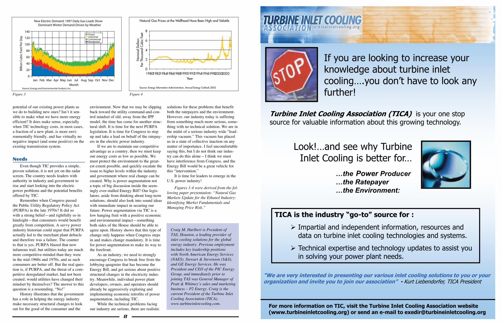
Environmental emissions increase during hot weather for two reasons: decreased energy efficiency of all combustion turbines, and startup of older, dirtier, and inefficient peaking plants. Operating these power plants at low efficiencies not only increases environmental emissions, they also consume more fuel (natural gas, fuel oil, or diesel) per unit of electric energy produced. Over the last 20 years, most of the new power plants brought on stream in the U.S. use natural gas (Figure 1), and electric genera-tion represents the highest demand sector for growth for natural gas (Figure 2). Natural gas demand for
6
450
400
350
300
250
200
150
100
50
0
Billi
on K
ilow
att H
ours
Oil Gas
Year1975 1980 1985 1990 1995 2000
New Electric Demand: Most New Generation Capacity Utilizes Natural Gas (Primarily for Environmental Reason)
Source: National Petroleum Council, Sept. '03
10
8
6
4
2
0
12
1990 1995 2000 2005 2010 2015 2020 2025
CNG vehicles
Projections
New Electric Demand: Electric Generation Represents the Highest Sector Demand Growth for Natural Gas
History
Source: Energy Information Administration, Annual Energy Outlook 2003
Commercial
Residential
Industrial
ElectricGenerators
Commercial
Residential
Industrial
ElectricGenerators
Figure 1 Figure 2
Greater summer power demand and more advanced gas turbines lead to an increased need for turbine inlet chilling. Photo courtesy of TAS, Ltd.
A Perspective on the U.S. Electric Power Industry
PROBLEMS, SOLUTIONS & NEEDSBy Craig M. Hurlbert
COOL YOUR JETS
text
9
Titleauthor
Appeared in January 2004 Energy-Tech Magazine
potential of our existing power plants as we do to building new ones? Isn’t it sen-sible to make what we have more energy efficient? It does make sense, especially when TIC technology costs, in most cases, a fraction of a new plant, is more envi-ronmentally friendly, and has virtually no negative impact (and some positive) on the existing transmission system.
NeedsEven though TIC provides a simple,
proven solution, it is not yet on the radar screen. The country needs leaders with authority in industry and government to rise and start looking into the electric power problems and the potential benefits offered by TIC.
Remember when Congress passed the Public Utility Regulatory Policy Act (PURPA) in the late 1970s? It did so with a strong belief—and rightfully so in hindsight—that consumers would benefit greatly from competition. A savvy power industry historian could argue that PURPA actually led to the merchant plant debacle and therefore was a failure. The counter to that is yes, PURPA blazed that now infamous trail, but utilities today are much more competitive-minded than they were in the mid-1960s and 1970s, and as such consumers are better off. But the real ques-tion is, if PURPA, and the threat of a com-petitive deregulated market, had not been created, would utilities have changed their mindset by themselves? The answer to this question is a resounding, “No!”
History illustrates that the government has a role in helping the energy industry make necessary structural changes to look out for the good of the consumer and the
environment. Now that we may be slipping back toward the utility command-and-con-trol mindset of old, away from the IPP model, the time has come for another struc-tural shift. It is time for the next PURPA legislation. It is time for Congress to step up and take a lead on behalf of the ratepay-ers in the electric power industry.
If we are to maintain our competitive advantage as a country, then we must keep our energy costs as low as possible. We must protect the environment to the great-est extent possible, and quickly escalate the issue to higher levels within the industry and government where real change can be created. Why is power augmentation not a topic of big discussion inside the seem-ingly ever-stalled Energy Bill? Our legis-lators, aside from thinking about long-term solutions, should also look into sound ideas with immediate impact in securing our future. Power augmentation via TIC is a low hanging fruit with a positive economic and environmental impact—something both sides of the House should be able to agree upon. History shows that this type of change only happens when Congress steps in and makes change mandatory. It is time for power augmentation to make its way to the forefront.
As an industry, we need to strongly encourage Congress to break free from the lobbying quagmire that has become the Energy Bill, and get serious about positive structural changes in the electricity indus-try. Meanwhile, individual power plant developers, owners, and operators should already be aggressively exploring and implementing economic retrofits of power augmentation, including TIC.
While the technical problems facing our industry are serious, there are realistic
solutions for these problems that benefit both the ratepayers and the environment. However, our industry today is suffering from something much more serious, some-thing with no technical solution. We are in the midst of a serious industry wide “lead-ership vacuum.” This vacuum has placed us in a state of collective inaction on any matter of importance. I feel uncomfortable saying this, but I do not think our indus-try can do this alone – I think we must have interference from Congress, and the Energy Bill would be a great vehicle for this “intervention.”
It is time for leaders to emerge in the U.S. power industry!
Figures 1-4 were derived from the fol-lowing paper presentation: “Natural Gas Markets Update for the Ethanol Industry: Identifying Market Fundamentals and Managing Price Risk.”
8
140
120
100
80
60
40
20
0
Billi
on C
ubic
Fee
t Per
Day
MonthSource: Energy and Environmental Analysis, Inc.
Jan Feb Mar Apr May Jun Jul Aug Sep Oct Nov Dec
New Electric Demand: 1997 Daily Gas Loads Show Dominant Winter Demand Driven by Weather
PowerIndustrialCommercialResidential
Year
Source: Energy Information Administration, Annual Energy Outlook 2003
Natural Gas Prices at the Wellhead Have Been High and Volatile
2002200019981996199419921990198819861984198219800
2
4
6
8
Nom
inal
Dol
lars
Per
Thou
sand
Cub
ic F
eet
Figure 3 Figure 4
Craig M. Hurlbert is President of TAS, Houston, a leading provider of inlet cooling solutions for the global energy industry. Previous employment includes key leadership positions with North American Energy Services (NAES), Stewart & Stevenson (S&S), and GE Energy Services. He was President and CEO of the PIC Energy Group, and immediately prior to joining TAS was General Manager of Pratt & Whitney’s sales and marketing business – P2 Energy. Craig is the current President of the Turbine Inlet Cooling Association (TICA), www.turbineinletcooling.com.
If you are looking to increase your knowledge about turbine inlet cooling….you don’t have to look any further!
Turbine Inlet Cooling Association (TICA) is your one stop source for valuable information about this growing technology.
Look!…and see why Turbine Inlet Cooling is better for…
…the Power Producer…the Ratepayer…the Environment:
“We are very interested in presenting our various inlet cooling solutions to you or your organization and invite you to join our association” - Kurt Liebendorfer, TICA President
For more information on TIC, visit the Turbine Inlet Cooling Association website (www.turbineinletcooling.org) or send an e-mail to [email protected]
TICA is the industry “go-to” source for :
Ø Impartial and independent information, resources and data on turbine inlet cooling technologies and systems.
Ø Technical expertise and technology updates to assist you in solving your power plant needs.
COOL YOUR JETS
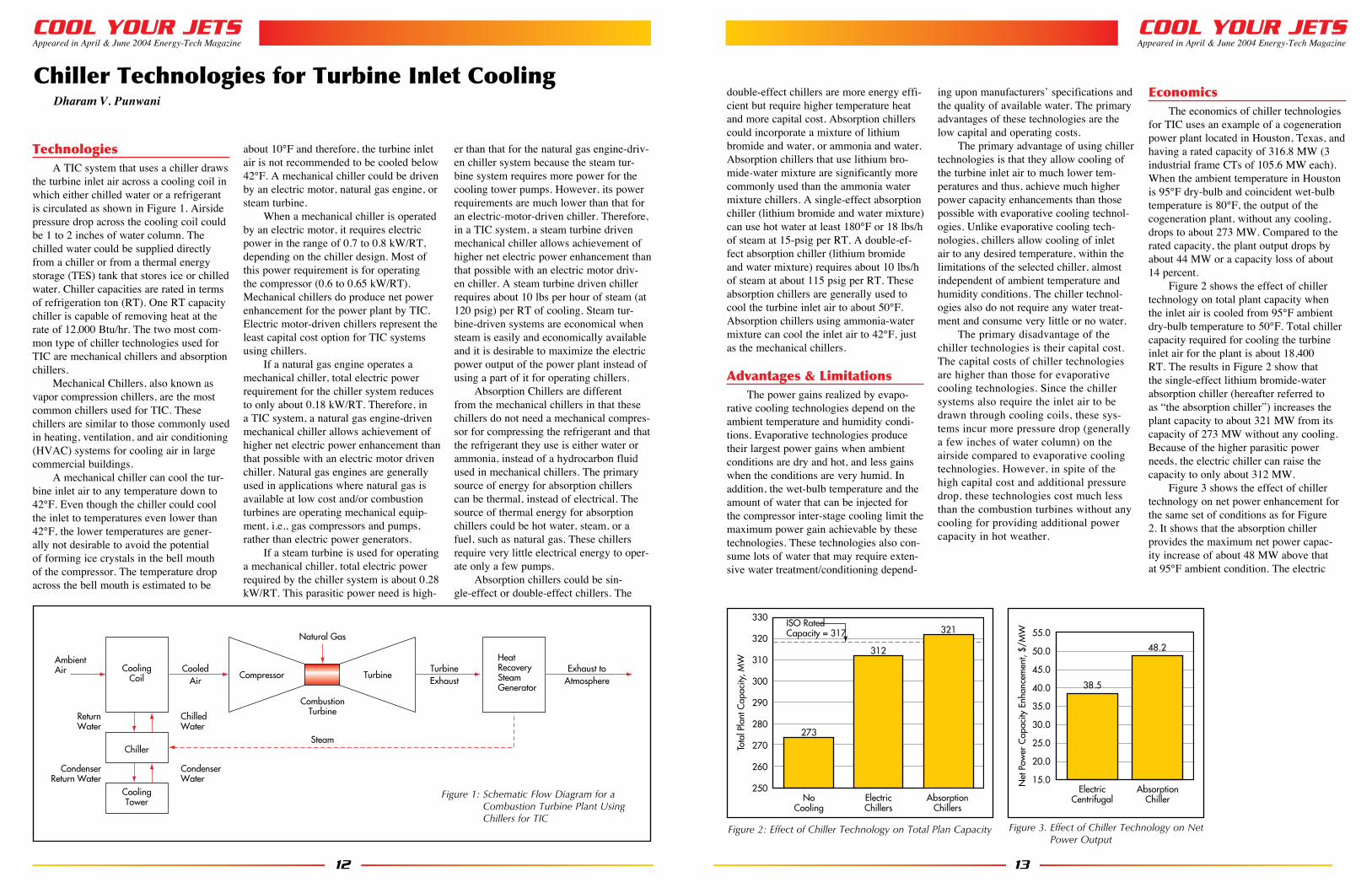
When the ambient temperature in Los Angeles is 87°F dry-bulb and coincident wet-bulb temperature is 64°F the output of the uncooled 83.5 MW and 42 MW (capaci-ties at ISO conditions of 59°F and 14.7 psia) cogeneration plants drops to about 75.3 MW and 32.1 MW, respectively as discussed in Figures 2 and 3 of the inaugural issue of this column in December 2003. Compared to the rated capacities of the two plants, the reduced outputs represent loss of capacity by about 10% and 24%, respectively.
Assuming 90% and 98% approaches to the difference between the dry-bulb and wet-bulb temperatures for the wetted media (evaporative cooling) and fogging technol-ogies, these two technologies can cool the inlet air to 66.3°F and 64.5°F respectively. Comparisons of the two evaporative cooling technologies with the uncooled CT in terms of total power plant output and incremental power are shown in Figures 1 and 2.
The results in Figure 1 show that wetted media and fogging can enhance the capaci-ties of the larger uncooled system from 75.3 MW to 81.3 MW and 81.9 MW, respec-tively. Therefore, these TIC technologies can restore most of the 10% lost capacity to within 3% of the rated capacity.
The results for the aeroderivative CT, shown in Figure 2, are similar but more pro-nounced than those for the industrial/frame CT. The capacity of this uncooled system goes up from 34.1 MW to 39.9 MW and 40.4 MW by the evaporative cooling and fogging technologies, respectively and thus, restores most of the 24% lost capacity to within 4% of the rated capacity.
The impacts of the two TIC technolo-gies on the installed cost for the total plant capacity for the two types of CTs are shown in Figures 3 and 4. The costs in these figures are based on the following installed costs:
Un-cooled CT plant:$750,000/MW at ISO conditions
Wetted Media:$19,000/MW CT capacity at ISO
Fogging:$19,000/MW CT capacity at ISOThe results in the above Figures show
that the total plant capital cost, expressed as $/MW, is lower for the plants with TIC than those for the uncooled systems.
The capital costs for the incre-mental power output capacities made available by TIC are shown in fig-ures 5 and 6. These figures show the capital costs for the additional power output capacity available from the existing CT by TIC are significantly lower than the option of installing an additional uncooled CT. This is one of the most important benefit of TIC.
As stated earlier, all of the above discussions relate to a situation when the ambient dry-bulb and wet-bulb temperatures are 87°F and 64°F, respectively. However, this informa-tion is not sufficient to decide wheth-er TIC is economically attractive and if so which cooling technology will be economically most attractive. Such estimates require calculations using hourly weather data for 8,760 hours of the year and also require information for cost of fuel, power demand profile and market value of power produced (which may vary with the time of day).
In addition, as stated earlier, the results of the various TIC tech-nologies for these plants located in Houston, TX and Las Vegas, NV would be different from those dis-cussed for Los Angeles, CA.
USERSMany CC plants across the
U.S are using various evaporative cooling technologies that best suit their needs. A database of some of these installations is available in the Experience Database section of the
Website (www.turbineineltcooling.org) of the Turbine Inlet Cooling Association.
11
740,000No Cooling Wetted Media
Cooling Technology
Fogging
790,000
840,000
890,000
940,000
Plan
t Cap
ital C
ost w
ith T
IC
780,954
792,029
924,784
720,000No Cooling Wetted Media
Cooling Technology
Fogging
740,000
760,000
780,000
800,000
820,000
840,000
Plan
t Cap
ital C
ost w
ith T
IC
766,794772,316
832,141
0No Cooling Wetted Media
Cooling Technology
Fogging
200,000
400,000
600,000
800,000
1,000,000
Incr
emen
tal P
lant
Cap
ital C
ost,
$/M
W
13,10913,779
924,784
Figure 4 Effect of Cooling Technology on Total Plant Capital Cost ($) for the Aeroderivative CT
Figure 5. Effect of Cooling Technology on Incre-mental Plant Capital Cost for the Industrial CT
Figure 6. Effect of Cooling Technology on Incremental Plant Capital Cost for the Aeroderivative CT
Dharam V. Punwani is president of Avalon Consulting, Inc. located in the Chicagoland area (Naperville), and has over 36 years of experience in energy technologies. Avalon pro-vides technical and economic analyses related to TIC andcogeneration systems. He was chairman of TICA in 2002 and now serves as its Executive Director.
COOL YOUR JETS
The inaugural issue of this column was published in the December 2003 issue of the Energy-Tech. It provided an introduction to the turbine inlet cooling (TIC) and addressed a number of frequently asked questions: What is it? Why use it? What are its bene-fits? How does it work? What are the tech-nology options? What are its economics? Who is using it? It also discussed plans for the future issues of this column and Energy-Tech’s plans for a cover story and a special supplement for TIC in cooperation with the Turbine Inlet Cooling Association (TICA).
As per the plans for this column, the current column discusses three evaporative technologies commercially used for TIC and their economics: wetted media, fogging, and wet compression/over spraying. These technologies differ from one another in the method and/or the quantity of water added to the inlet air entering the compressor of a CT system. All technologies have their pros and cons. As discussed in the inaugu-ral issue of this column, the selection of an optimum technology for a specific power plant depends on a number of factors, including plant’s geographical location, CT characteristics, plant operating mode, market value of electric energy, and fuel cost. Many published articles are available on these technologies. A number of these publica-tions are listed in the Library section of the Website (www.turbineinletcooling.org) of the Turbine Inlet Cooling Association.
TechnologiesThe primary advantages of evaporative
cooling technologies are their low capital and operating costs. The primary disadvan-tage of these technologies is that the extent of cooling achieved is limited to the wet-bulb temperature (WB) and, therefore, their outputs vary depending upon the weather. These technologies are more efficient in hot and dry weather and less efficient in hot and humid weather conditions. These technol-ogies also consume lots of water and may require water treatment/conditioning depend-ing upon manufacturers’ specifications and the quality of available water.
Wetted media is the first technology used for TIC. In this technology, water is added to the inlet air by exposing it to a film of water in one of the many types of wetted media. Honey-comb-like medium is one of the most commonly employed media. The water used for wetting the medium may require treatment, depending upon the qual-ity of water and the medium manufacturer’s specifications. Wetted media can cool the inlet to within 85% to 95% of the difference between the ambient dry-bulb and wet-bulb temperature. On an overall basis, this is the most widely used technology.
In Fogging, water is added to the inlet air by spraying very fine droplets of water. Fogging systems can be designed to produce droplets of variable sizes, depending on the desired evaporation time and ambient con-
ditions. The water droplet size is generally less than 40 microns and on an average it is about 20 microns. The water used for fogging typically requires demineraliza-tion. Fogging systems can cool the inlet air to within 95% to 98% of the difference between ambient dry-bulb and wet-bulb tem-perature and is therefore, slightly more effec-tive than the wetted media. Its capital cost is very comparable to that for the wetted media and it is the second most applied technology for TIC.
In Wet Compression/Over Spraying water is added to the inlet air as a fog just as it is done for fogging. However, the amount of fog added is a lot more than can be evap-orated under the conditions of the ambient air. The inlet air stream carries the excess fog into the compressor section of the CT where it further evaporates, cools the com-pressed air and creates extra mass for boost-ing the CT output beyond that possible with the evaporative cooling technologies. The amount of excess fog carried into the com-pressor depends on where the fog is added in the inlet section of the CT system.
EconomicsFor the purpose of discussing the eco-
nomics of wetted media and fogging, we will use examples of the following two types of cogeneration plants located in Los Angeles, CA:
1. 83.5 MW Industrial/Frame CT2. 42.0 MW Aeroderivative CT
10
Evaporative Cooling Technologies for Turbine Inlet Cooling
Dharam V. Punwani
71.0No CoolingWetted Media
Cooling Technology
Fogging
75.3
81.3
73.0
75.0
77.0
79.0
81.0
83.0
85.0
Pow
er O
utpu
t, M
W
81.9
30.0No CoolingWetted Media
Cooling Technology
Fogging
34.1
39.9
32.0
34.0
36.0
38.0
40.0
42.0
44.0
Pow
er O
utpu
t, M
W
40.4
Figure 1. Effect of Cooling Technology on Net Power Output of the Industrial CT
Figure 2. Effect of Cooling Technology on Net Power Output of the Aeroderivative CT
Figure 3. Effect of Cooling Technology on Total Plant Capital Cost ($) for the Industrial CT
730,000No CoolingWetted Media
Cooling Technology
Fogging
740,000750,000760,000770,000780,000790,000800,000810,000820,000830,000840,000
Plan
t Cap
ital C
ost w
ith T
IC
766,794772,316
832,141
COOL YOUR JETSAppeared in April & June 2004 Energy-Tech Magazine
double-effect chillers are more energy effi-cient but require higher temperature heat and more capital cost. Absorption chillers could incorporate a mixture of lithium bromide and water, or ammonia and water. Absorption chillers that use lithium bro-mide-water mixture are significantly more commonly used than the ammonia water mixture chillers. A single-effect absorption chiller (lithium bromide and water mixture) can use hot water at least 180°F or 18 lbs/h of steam at 15-psig per RT. A double-ef-fect absorption chiller (lithium bromide and water mixture) requires about 10 lbs/h of steam at about 115 psig per RT. These absorption chillers are generally used to cool the turbine inlet air to about 50°F. Absorption chillers using ammonia-water mixture can cool the inlet air to 42°F, just as the mechanical chillers.
Advantages & Limitations The power gains realized by evapo-
rative cooling technologies depend on the ambient temperature and humidity condi-tions. Evaporative technologies produce their largest power gains when ambient conditions are dry and hot, and less gains when the conditions are very humid. In addition, the wet-bulb temperature and the amount of water that can be injected for the compressor inter-stage cooling limit the maximum power gain achievable by these technologies. These technologies also con-sume lots of water that may require exten-sive water treatment/conditioning depend-
ing upon manufacturers’ specifications and the quality of available water. The primary advantages of these technologies are the low capital and operating costs.
The primary advantage of using chiller technologies is that they allow cooling of the turbine inlet air to much lower tem-peratures and thus, achieve much higher power capacity enhancements than those possible with evaporative cooling technol-ogies. Unlike evaporative cooling tech-nologies, chillers allow cooling of inlet air to any desired temperature, within the limitations of the selected chiller, almost independent of ambient temperature and humidity conditions. The chiller technol-ogies also do not require any water treat-ment and consume very little or no water.
The primary disadvantage of the chiller technologies is their capital cost. The capital costs of chiller technologies are higher than those for evaporative cooling technologies. Since the chiller systems also require the inlet air to be drawn through cooling coils, these sys-tems incur more pressure drop (generally a few inches of water column) on the airside compared to evaporative cooling technologies. However, in spite of the high capital cost and additional pressure drop, these technologies cost much less than the combustion turbines without any cooling for providing additional power capacity in hot weather.
EconomicsThe economics of chiller technologies
for TIC uses an example of a cogeneration power plant located in Houston, Texas, and having a rated capacity of 316.8 MW (3 industrial frame CTs of 105.6 MW each). When the ambient temperature in Houston is 95°F dry-bulb and coincident wet-bulb temperature is 80°F, the output of the cogeneration plant, without any cooling, drops to about 273 MW. Compared to the rated capacity, the plant output drops by about 44 MW or a capacity loss of about 14 percent.
Figure 2 shows the effect of chiller technology on total plant capacity when the inlet air is cooled from 95°F ambient dry-bulb temperature to 50°F. Total chiller capacity required for cooling the turbine inlet air for the plant is about 18,400 RT. The results in Figure 2 show that the single-effect lithium bromide-water absorption chiller (hereafter referred to as “the absorption chiller”) increases the plant capacity to about 321 MW from its capacity of 273 MW without any cooling. Because of the higher parasitic power needs, the electric chiller can raise the capacity to only about 312 MW.
Figure 3 shows the effect of chiller technology on net power enhancement for the same set of conditions as for Figure 2. It shows that the absorption chiller provides the maximum net power capac-ity increase of about 48 MW above that at 95°F ambient condition. The electric
13
330
320
310
300
290
280
270
260
250
Tota
l Pla
nt C
apac
ity, M
W
NoCooling
273
ElectricChillers
312
AbsorptionChillers
321ISO Rated Capacity = 317 55.0
50.0
45.0
40.0
35.0
30.0
25.0
20.0
15.0Net
Pow
er C
apac
ity E
nhan
cem
ent,
$/M
W
ElectricCentrifugal
AbsorptionChiller
38.5
48.2
Figure 2: Effect of Chiller Technology on Total Plan Capacity Figure 3. Effect of Chiller Technology on Net Power Output
TechnologiesA TIC system that uses a chiller draws
the turbine inlet air across a cooling coil in which either chilled water or a refrigerant is circulated as shown in Figure 1. Airside pressure drop across the cooling coil could be 1 to 2 inches of water column. The chilled water could be supplied directly from a chiller or from a thermal energy storage (TES) tank that stores ice or chilled water. Chiller capacities are rated in terms of refrigeration ton (RT). One RT capacity chiller is capable of removing heat at the rate of 12,000 Btu/hr. The two most com-mon type of chiller technologies used for TIC are mechanical chillers and absorption chillers.
Mechanical Chillers, also known as vapor compression chillers, are the most common chillers used for TIC. These chillers are similar to those commonly used in heating, ventilation, and air conditioning (HVAC) systems for cooling air in large commercial buildings.
A mechanical chiller can cool the tur-bine inlet air to any temperature down to 42°F. Even though the chiller could cool the inlet to temperatures even lower than 42°F, the lower temperatures are gener-ally not desirable to avoid the potential of forming ice crystals in the bell mouth of the compressor. The temperature drop across the bell mouth is estimated to be
about 10°F and therefore, the turbine inlet air is not recommended to be cooled below 42°F. A mechanical chiller could be driven by an electric motor, natural gas engine, or steam turbine.
When a mechanical chiller is operated by an electric motor, it requires electric power in the range of 0.7 to 0.8 kW/RT, depending on the chiller design. Most of this power requirement is for operating the compressor (0.6 to 0.65 kW/RT). Mechanical chillers do produce net power enhancement for the power plant by TIC. Electric motor-driven chillers represent the least capital cost option for TIC systems using chillers.
If a natural gas engine operates a mechanical chiller, total electric power requirement for the chiller system reduces to only about 0.18 kW/RT. Therefore, in a TIC system, a natural gas engine-driven mechanical chiller allows achievement of higher net electric power enhancement than that possible with an electric motor driven chiller. Natural gas engines are generally used in applications where natural gas is available at low cost and/or combustion turbines are operating mechanical equip-ment, i.e., gas compressors and pumps, rather than electric power generators.
If a steam turbine is used for operating a mechanical chiller, total electric power required by the chiller system is about 0.28 kW/RT. This parasitic power need is high-
er than that for the natural gas engine-driv-en chiller system because the steam tur-bine system requires more power for the cooling tower pumps. However, its power requirements are much lower than that for an electric-motor-driven chiller. Therefore, in a TIC system, a steam turbine driven mechanical chiller allows achievement of higher net electric power enhancement than that possible with an electric motor driv-en chiller. A steam turbine driven chiller requires about 10 lbs per hour of steam (at 120 psig) per RT of cooling. Steam tur-bine-driven systems are economical when steam is easily and economically available and it is desirable to maximize the electric power output of the power plant instead of using a part of it for operating chillers.
Absorption Chillers are different from the mechanical chillers in that these chillers do not need a mechanical compres-sor for compressing the refrigerant and that the refrigerant they use is either water or ammonia, instead of a hydrocarbon fluid used in mechanical chillers. The primary source of energy for absorption chillers can be thermal, instead of electrical. The source of thermal energy for absorption chillers could be hot water, steam, or a fuel, such as natural gas. These chillers require very little electrical energy to oper-ate only a few pumps.
Absorption chillers could be sin-gle-effect or double-effect chillers. The
12
Chiller Technologies for Turbine Inlet CoolingDharam V. Punwani
CoolingCoil
Chiller
AmbientAir
CoolingTower
CooledAir
HeatRecoverySteamGenerator
Exhaust toAtmosphere
TurbineExhaust
CondenserWater
CondenserReturn Water
ChilledWater
ReturnWater
Compressor Turbine
Natural Gas
CombustionTurbine
Steam
Figure 1: Schematic Flow Diagram for a Combustion Turbine Plant Using Chillers for TIC
COOL YOUR JETSAppeared in April & June 2004 Energy-Tech Magazine
chiller provides a capacity enhancement of about 39 MW. The results in figures 2 and 3 are based on total parasitic loads of 0.81 kW/RT and 0.28 kW/RT for the electric and absorption chillers, respectively, and cooling coil pressure drop of 1.5 inches of water column.
Figure 4 shows the effect of cooling technology on total plant (power plant plus TIC system) cost per MW of the net capacity of the plant for similar conditions as those for Figure 2. The costs in Figure 4 are based on the following installed costs for the power plant and TIC sys-tems: $750,000/MW for the cogeneration plant at the rated capacity, $834/RT for the complete (with cooling coil, chillers, pumps, demisters, and cooling towers) TIC system with electric chillers, and $1,240/RT for the complete TIC system with the absorption chiller. Please note that usually the costs of installing TIC systems with chillers are not as high as those in this example. The reason for the higher costs in this example is because for retrofitting the plant that had limited area for install-ing cooling coil, the chilled water had to be produced at 40°F, instead of the usual 44°F. Therefore, the chiller costs include the effect of chiller de-rating to produce water at 40°F. In addition, the capital cost differential between the absorption and electric chiller systems is also not as high as in this example. The absorption chiller system cost is high here because it also includes the cost of the heat recov-ery equipment required for producing hot
water (needed for operating the absorption chiller) from the exhaust of the heat recov-ery steam generator (HRSG). On these bases, the total cost of the cogeneration plant without TIC is $237.6 million. When the ambient temperature rises to 95°F and its total capacity decreases to 273 MW, the effective capital cost of the cogene-ration plant rises from $750,000/MW to about $870,000/MW for the same total investment of $237.6 million. The results in Figure 4 show that the total plant cost is the lowest for the plant with the TIC sys-tem using the absorption chiller.
Figure 5 shows the effect of chiller technology on the total cost for the incre-mental power capacity enhancement above the capacity of the plant at 95°F for the same set of conditions discussed above for Figure 4. It shows that both TIC systems provide incremental power at nearly half the cost of an uncooled system and that the TIC system using electric chillers provides the incremental capacity at the lowest cost of $398,000/MW.
The estimates in Figures 2 through 5 are only “snapshot” results when the ambi-ent dry-bulb temperature is 95°F and the
turbine inlet air is cooled to 50°F for the plant’s location in Houston. On the basis of the information in these figures, it is pre-mature to draw any conclusion about the optimum technology for this plant. Further analyses are necessary, using hourly weather data for all 8,760 hours of the year for estimating the net annual production of electrical energy (MWh) and steam, and their respective market values and annual operating and maintenance costs.
SummaryTIC systems using chillers allow com-
bustion turbine systems to produce rated or even higher than rated power capacity, independent of high ambient temperatures. These systems provide incremental capac-ity enhancement at almost one-half the per MW capital cost of the uncooled combus-tion turbine systems.
COOL YOUR JETSAppeared in April, & June 2004 Energy-Tech Magazine
14
1,000,000
900,000
800,000
700,000
600,000
500,000
400,000
300,000
200,000
Incr
emen
tal C
apita
l Cos
t for
Pow
erC
apac
ity E
nhan
cem
ent,
$/M
W
Electric Chiller Absorption Chiller
398,000
472,328
No Cooling
869,911
Figure 5. Effect of Chiller Technology on Capital Cost for Incremental Plant Capacity Enhancement
Dharam V. Punwani is president of Avalon Consulting, Inc. locat-ed in the Chicagoland area (Naperville), and has over 36 years of experience in energy technologies. Avalon provides technical and economic analyses related to TIC and cogeneration systems. He was chairman of TICA in 2002 and now serves as its Executive Director.
880,000
870,000
860,000
850,000
840,000
830,000
820,000
810,000
800,000
Tota
l Pla
nt C
ost I
nclu
ding
TI
C S
yste
m, $
/MW
AbsorptionChiller
ElectricChiller
810,285 811,616
NoCooling
869,911
Figure 4. Effect of Chiller Technology on Total Plant Investment

R
Prestressed Concrete Tanks
CROM
250 S.W. 36TH TERRACEGAINESVILLE, FL 32607
PHONE: (352) 372-3436 FAX: (352) 372-6209www.cromcorp.com
R
R
R
R
Butler-Warner Generating Plant - Fayetteville, NC
High Quality Long Life Virtually Maintenance Free
Designing and constructing superiorliquid storage structures since 1953.
CROM is a leading provider of Thermal EnergyStorage Tanks for Commercial, Industrial
and Power Generating Applications
West County Generating Plant - Palm Beach County, FL Central Chiller Plant - Daytona State College, FL
16
The TES ConceptA TES-TIC system utilizes all the
component elements of a non-TES chiller-based TIC system. However, TES allows for the time-based decou-pling of all or some of the chiller plant operation from the usage of cooling at the turbine’s inlet air cooling coils. This is accomplished by operating chillers during off-peak times (when the value of power is relatively low) to freeze ice or to chill a storage tank of water or fluid. Subsequently, during on-peak periods (when the value of power is high) the storage is utilized (melting the ice or reheating the stored water or fluid) to meet peak cooling loads at the turbine inlet air cooling coils.
A dual-benefit is achieved by utiliz-ing TES in this manner:
1. Parasitic loads associated with chiller operation are eliminated or largely reduced during on-peak periods when power is at its highest value. (The chillers operate entire-ly or primarily during off-peak periods, when the cost or value of power is lower.)
2. The chiller plant can be reduced in capacity and capital cost, often more than compensating for the capital cost of the TES installation.
Advantages & Limitations of TES
All TIC technologies have advantag-es and limitations. It is always important to understand and evaluate technology options for each application.
The use of TES for TIC maintains the basic attributes and benefits of a non-TES chiller system used for TIC. TES allows cooling of the turbine inlet air to temperatures lower than those possible with evaporative cooling technologies and thus, achieves much higher power capac-ity enhancement. The TES-chiller system allows cooling of inlet air to any desired temperature within the limitations of the selected chiller(s). The TES-chiller system does not require elaborate water treatment and consumes very little water compared to evaporative cooling.
TES systems are most often mated to electric motor-driven chillers; however, TES systems are also frequently applied with steam turbine-driven, engine-driven, and absorption chiller systems, as well as with hybrid systems using a mix of chiller technologies.
Supplementing a chiller system with TES helps to address the non-TES chiller system’s primary drawback, namely a rela-tively high capital cost compared to evapo-rative cooling systems.
The Key Advantages of TES for TIC1. Reduced parasitic power losses,
on-peak2. Reduced capacity and cost of chiller
plant3. Lower capital cost per MW of
power enhancement, on-peak4. Maximized net power enhancement,
on-peak
The Key Limitations of TES for TIC1. Space for the TES tank2. Limited hours per day of maximum
power enhancement
Comparing TES Options for TIC
Various TES technology options are available and already in use in TIC applications. There are two families of TES technologies:
1. Latent heat TES, notably ice (i.e., “static” ice TES such as “ice-on-coil,” or “encapsulated ice” and “dynamic” ice TES such as “ice harvesters”)
2. Sensible heat TES including chilled water (CHW) and low temperature fluid (LTF) storage.
Each technology has unique charac-teristics and therefore inherent advantages and limitations.
As each TES technology has charac-teristics that range from excellent to poor, a thorough knowledge of those differences (and of the priorities of a particular appli-cation) is critical to achieving an optimum match for any specific situation. Beyond the choice of technology, there are many other variables to be considered in apply-ing TES. These variables include such items as: full-shift versus partial-shift sys-tems; daily versus weekly design cycles; operating supply and return temperatures; chiller and chiller driver types; redundant chiller capacity (if any); and siting of the TES equipment.
Thermal Energy Storage Technologies for Turbine Inlet Cooling
John S. Andrepont
Table 1: Generalized Inherent Characteristics of TES Technologies for TIC
Latent Heat (Ice) TES Sensible Heat TES Static Ice Dynamic Ice Chilled Water LT FluidVolume good fair poor fair
Footprint good good fair good
Modularity excellent good poor good
Economy-of-Scale poor fair excellent good
Energy Efficiency fair fair excellent good
Low Temp Capability good good fair excellent
Ease of Retrofit to Chillers fair poor excellent good
Rapid Discharge Capability fair excellent good good
Simplicity and Reliability fair-good fair excellent good
Site Remotely from Chillers poor poor excellent excellent
Dual-Use as Fire Protection poor poor excellent poor
COOL YOUR JETSAppeared in August 2004 Energy-Tech Magazine
Hybrid SystemsDepending on the power plant design
and its load characteristics, a mix of TIC technologies might provide better econom-ics than any one of the individual technolo-gies. Some of the hybrid systems that have been successfully used include mechanical and absorption chillers, mechanical chillers and TES, absorption chillers with TES, and mechanical and absorption chillers with TES.
There are some hybrid systems that are technically possible, but economically undesirable. Examples of such systems include, initial cooling by wetted media or fogging followed by further cooling with chillers or TES. It might appear attractive to consider cooling the inlet air first by using wetted media or fogging because these are the lowest capital cost options and then use chillers or TES to further cool the air down to the desired lower tempera-ture. However, such hybrid systems are economically unattractive. The explanation for this is discussed in the full version of this column at www.energy-tech.com and www.turbineinletcooling.org.
Using wetted media or fogging after cooling the inlet air by chillers or TES also is not advisable because the air exiting the cooling coils of the chiller systems would be at or near saturation with very little or no scope for further cooling by evaporation.
However, if a power plant initially had a fogging system and later on decides to install a chiller system to meet increased demand, the fogging does not have to be removed. This type of hybrid system will provide the plant owner the flexibility to use only the fogging system when it is adequate to meet the power demand and use chillers only when the demand exceeds the power output possible with the fogging system.
Technical Considerations Favoring Hybrid Systems
A 316.8 MW cogeneration plant located in Texas consists of three gas tur-bines, each with a rated capacity of 105.6 MW. It produces steam as a coproduct that is sold to an adjacent chemical power
plant. The plant was originally built in 1982 and a fogging system was added to it at a later date for cooling the turbine inlet air. In 1998, plant management decided to consider other TIC options for increasing the power output of the plant to increase their revenues from the sale of electric power during on-peak period of 10 hours per day.
On the basis of the typical annual hourly weather data for the plant location, the maximum cooling load for the plant was estimated to be 20,830 TR for cooling the inlet air to 50°F. However, the dry-bulb temperature and the coincident wet-bulb temperature corresponding to that cooling load occur for only one hour in a year. In discussions with the plant management, it was decided that the total TIC capacity of 18,400 TR would be acceptable. This cool-ing capacity would be adequate for nearly 99 percent of the typical annual weather data.
Since the cogeneration plant could sell all the steam it could produce at an attrac-tive price, the option of using steam-heated absorption chillers and steam turbine-driv-en mechanical chillers were not desirable for this plant. As the power plant owners wanted to market maximum power during the on-peak period, an electrically driven mechanical chiller was not believed to be the preferred option for TIC.
Because the power plant had high power demand only during on-peak peri-od, it was planned to use TIC only during the on-peak period. Therefore, the use of TES was considered imperative in order to minimize the installed capacities of the chillers.
The temperature of the exhaust gas from the existing heat recovery steam gen-erator (HRSG) was 340°F. An analysis of the HRSG exhaust gases showed that these gases could be cooled to 286°F without causing condensation. Further analysis showed that cooling these exhaust gases could produce enough hot water to operate a hot water heated, single effect (HWSE) absorption chiller with a maximum capaci-ty of 8,300 tons of refrigeration (TR).
A detailed analysis of the cooling coil design for the TIC system showed
that the optimum temperature of the chilled water should be 38°F in order to fit the cooling coil in the available space for this retrofit application. As discussed in an earlier column, we cannot achieve 38°F temperature of chilled water from an absorption chiller. The best it can do is to deliver chilled water at 41°F and the chiller would require some derating of its rated capacity (at standard chilled water temperature of 44°F). Therefore, it was decided that we would have to use an electric driven mechanical chiller to cool the chilled water at 41°F, from the HWSE absorption chiller, to the desired tem-perature of 38°F. The capacity of such a chiller was estimated to be 1,200 TR.
As total chilling capacity required during the on-peak period was estimat-ed to be 18,400 TR and the two chillers could supply only a total of 9,500 TR, the balance 8,900 TR must be planned to come from the TES system. Since the total on-peak period is for 10 hours, the TES capacity should be at least a 89,000 ton-hr. Therefore, the hybrid system for the plant that might be the optimum for the subject cogeneration plant would consist of a 8,300 TR HWSE absorption chiller, a 1,200 TR electric-driven mechanical chiller, and a 89,000 ton-hr TES system. Additional options for hybrid systems for this plant and the economics of some of the options are available in the full version of this col-umn at www.energy-tech.com and www.turbineinletcooling.org.
LNG-Based TICThere are several LNG terminals
across the U.S. where natural gas is stored as a liquid or LNG is imported from over-seas in tankers. The LNG terminals are used as a resource to meet peak demands of natural gas. With the current high pric-es of natural gas many energy companies are considering and installing additional LNG facilities in the U.S. and elsewhere. The off-loading of LNG from a tanker into a natural gas pipeline and/or for use in a power plant requires the re-vaporization of the natural gas. LNG in its liquid state is at -258°F. Therefore, it can be converted readily into the vapor phase with low-level
Hybrid Systems & LNG for Turbine Inlet Cooling (TIC)Dharam V. Punwani
COOL YOUR JETSAppeared in October 2004 Energy-Tech Magazine
19
COOL YOUR JETS
18
Appeared in August 2004 Energy-Tech Magazine
Specific Users of TES-TICTo date, there has been more than 15
years of experience with TES-TIC installa-tions. Such applications span a wide range of application types:
7 TIC applied to new CTs, as well as retrofits to existing CTs;
7 Applications for Simple-Cycle and Combined-Cycle CT plants;
7 CT plant capacities ranging from 1 MW to 750 MW;
7 Installations in North America, Europe, and Asia, including a wide range of climates, both hot-arid and hot-humid environments, as well as locales with year-round hot weather and those with only brief seasonal hot weather; and
7 Various TES technology types, including Ice TES, Stratified Chilled Water (CHW) TES, and Stratified Low Temperature Fluid (LTF) TES.
The types of power plants using TES-TIC systems are mostly stand-alone power generation (utilities and IPPs). However, TES-TIC is also fairly common at District Energy systems (both at urban thermal utility systems and at university campus energy systems) where central cooling plants and onsite power genera-tion are employed.
Power plants across the U.S. and around the globe are employing various TES-TIC technologies, with the earli-est documented system in-service in the
late 1980s. Detailed data from some of these installations is available within the Experience Database section of the Turbine Inlet Cooling Association website, www.turbineinletcooling.org.
Case Study of TES-TIC Systems
Details for a representative recent example is provided in the following Electric Utility Case Study.
Plant & TES-TIC Data7 Middle East (hot-arid climate)7 Existing 750 MW (ISO) Simple-
Cycle plant7 10 x GE 7EA CTs7 Added TIC, from 122°F to 54.5°F air
temp7 Approx. 30,000-ton TIC load, 6
hours per day7 Added approx. 11,000-ton elec-
tric-driven mechanical chiller plant7 Added 193,000 ton-hours of stratified
chilled water TES (full load shift)
TES-TIC Results7 TES-TIC in-service in 20047 30% enhancement in hot weather
power output7 Low unit capital cost per MW of
power enhancement7 Use of TES saved approx. 20,000 tons
of installed chiller plant capacity7 Use of TES reduced on-peak par-
asitic loads (increased net on-peak power) by approx. 20 MW
7 Use of TES saved approx. $10 mil-lion in capital cost versus a non-TES TIC chiller system
SummaryNo one technology is universally
best for all TIC applications. TES-TIC systems are being increasingly applied, particularly where the value of electric power varies significantly as a function of time-of-day on hot weather days. Of all available TIC technologies, TES-TIC systems provide the maximum hot weath-er CT power enhancement during on-peak periods. TES-TIC also offers significant reductions in total capital cost and in unit capital cost per MW of on-peak power enhancement, compared to non-TES chiller systems for TIC. TES is an option that should be considered and explored whenever maximized on-peak hot weath-er performance is desirable.
NOTE: This column was edited from its original format. Read the column in its entirety at www.turbineinletcooling.org, where you will also find: a table outlining generalized characteristics of TES tech-nologies; a table analysis of recent TIC-TES installations; and an additional tech-nology case study on Combined Cooling, Heat & Power.
John S. Andrepont is the founder and president of The Cool Solutions Company, Lisle, Ill., and has 30 years of experience in energy technologies, including various turbine inlet cooling projects and over 100 thermal energy storage installations. Cool Solutions provides consulting services related to TIC, TES, and District Cooling systems. He is the current chairman and director of the Turbine Inlet Cooling Association (TICA).
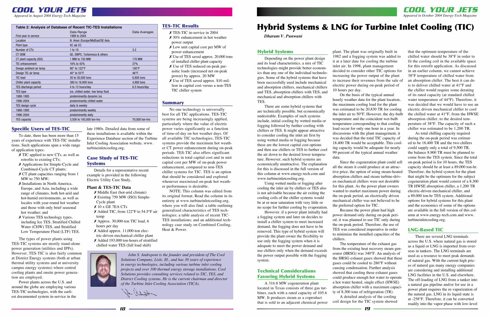
Table 2: Analysis of Database of Recent TIC-TES Installations Data Range Data AveragesFirst year in service 1988 to 2004
Location N. Amer./Europe/MidEast/SE Asia
Plant type SC a& CC
Number of CTs 1 to 10 3.2
CT OEM GE, SWPC, Turbomeca & others
CT plant capacity (ISO) 1 MW to 750 MW 170 MW
TIC enhancement 16% to 42% 27%
Design ambient air temp 90° to 122°F 100°F
Design TIC air temp 40° to 55°F 46°F
TIC load 30 to 30,000 tons 6,800 tons
Chiller plant capacity 380 to 16,800 tons 4,900 tons
TES discharge period 4 to 13 hours/day 6.5 hours/day
TES type ice, chilled water, low temp fluid
1988-1995 predominantly dynamic ice
1996-2004 predominantly chilled water
TES design cycle daily & weekly
1988-1995 predominantly weekly
1996-2004 predominantly daily
TES capacity 3,500 to 193,000 ton-hrs 70,000 ton-hrs
20
Turbine Inlet Cooling (TIC)INSTALLATION SUCCESS STORIES
IntroductionNumerous success stories portray the
benefits of TIC installations. The examples described here serve to illustrate the very broad scope of applications. Specifically, they cover:
t Power plant capacities from 1 MW to 750 MW
t Simple-cycle and combined-cycle applications
t New construction and retrofit situa-tions
t Electric utility and independent power/District Energy/Distributed Generation owners
t Electric motor-driven, absorption, steam turbine-driven, and hybrid chiller plants
t Real-time (or “on-line”) chilling and Thermal Energy Storage (TES) sys-tems
t Locales including FL, IL, NY, OK, and the Middle East/Persian Gulf region
t Systems operating for more than 10 years and others just coming on-line
ABSORPTION COOLING
Trigen Energy Corporation
Nassau County, New YorkA District Energy system in Nassau
County, Long Island, N.Y., serves varied public and private sector thermal energy users (a large community college, medical
center, sports coliseum, hotel, museum complex, etc.) with heating and cooling. The central Combined Heat & Power (CHP) plant comprises:
t A nominal 57 MW of electric power in a CT Combined Cycle (CTCC)n 42 MW from the CTn 15 MW from the steam turbine
t 267 MWt of steam heatt 16,400 tons of chilled water coolingA TIC system was retrofitted to the
existing CTCC in the winter of 1996/97. The 1991 GE MS6001B CT was fitted with three banks of six chilled water (CHW) coils each in the inlet filter house. Coil design allowed inlet air with dry bulb/wet bulb temperatures of 92°/76°F (33°/24°C) to be cooled to 46.5°F (8°C), using CHW supply and return temperatures of 43°/60°F (6°/16°C). Design airflow was 240,000 cfm for a cooling load of 1,880 tons. Airside pressure drop was limited to 1.5 inches of water column (for the coils and the ducting) in order to minimize the negative impact of inlet air pressure losses on the CT power output. Simultaneously with the coil installation, a new 1,200 ton single-stage Lithium-Bromide and water absorption chiller was added to the exist-ing 15,200 tons of steam turbine-driven chillers. (The mismatch in cooling coil load and chiller capacity was not an issue due to some excess installed cooling capacity in the existing chiller plant.)
The 1997 results exceeded expecta-tions. Inlet air temperature was maintained at 46°F (8°C) during a period of 98°F
(37°C) ambient dry bulb air temperature. CT power output was increased by approx-imately 8 MW (a 23.5 percent increase). And CT heat rate was improved by approx-imately 5 percent. As an added benefit, condensate run-off is collected from the inlet cooling coils and used for cooling tower make-up in the District Cooling plant.
Total project installation costs were $809,000 for the TIC portion and $671,000 for the absorption cooling addition. Simple payback for the project was slightly over three years. Total unit capital cost was $185 per kW of incremental power output, well below half the installed unit cost of new simple cycle CT capacity (typically $400 to $500 per kW). Of course the over-all project economics were aided by the presence of the existing District Cooling plant equipment (without which, larger absorption chiller capacity and new cool-ing tower capacity would also have been required).
MECHANICAL COMPRESSION REFRIGERATION
Trigen Energy Corporation
Chicago, Oklahoma City, Tulsa, Okla.
District Energy (heating and cooling) systems in Chicago, Oklahoma City, and Tulsa each utilize one or more 1 MW
21
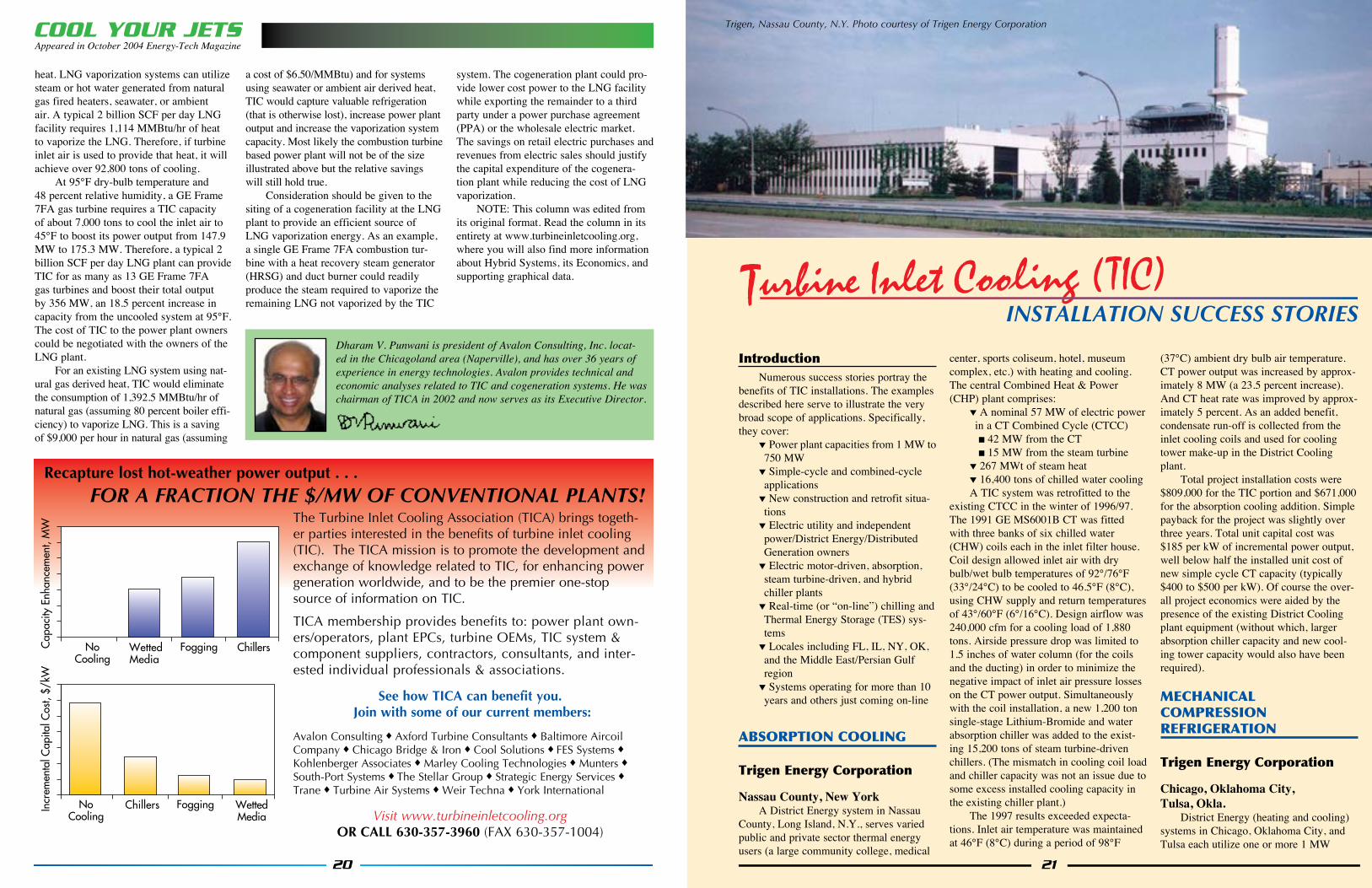
Trigen, Nassau County, N.Y. Photo courtesy of Trigen Energy CorporationCOOL YOUR JETSAppeared in October 2004 Energy-Tech Magazine
heat. LNG vaporization systems can utilize steam or hot water generated from natural gas fired heaters, seawater, or ambient air. A typical 2 billion SCF per day LNG facility requires 1,114 MMBtu/hr of heat to vaporize the LNG. Therefore, if turbine inlet air is used to provide that heat, it will achieve over 92,800 tons of cooling.
At 95°F dry-bulb temperature and 48 percent relative humidity, a GE Frame 7FA gas turbine requires a TIC capacity of about 7,000 tons to cool the inlet air to 45°F to boost its power output from 147.9 MW to 175.3 MW. Therefore, a typical 2 billion SCF per day LNG plant can provide TIC for as many as 13 GE Frame 7FA gas turbines and boost their total output by 356 MW, an 18.5 percent increase in capacity from the uncooled system at 95°F. The cost of TIC to the power plant owners could be negotiated with the owners of the LNG plant.
For an existing LNG system using nat-ural gas derived heat, TIC would eliminate the consumption of 1,392.5 MMBtu/hr of natural gas (assuming 80 percent boiler effi-ciency) to vaporize LNG. This is a saving of $9,000 per hour in natural gas (assuming
a cost of $6.50/MMBtu) and for systems using seawater or ambient air derived heat, TIC would capture valuable refrigeration (that is otherwise lost), increase power plant output and increase the vaporization system capacity. Most likely the combustion turbine based power plant will not be of the size illustrated above but the relative savings will still hold true.
Consideration should be given to the siting of a cogeneration facility at the LNG plant to provide an efficient source of LNG vaporization energy. As an example, a single GE Frame 7FA combustion tur-bine with a heat recovery steam generator (HRSG) and duct burner could readily produce the steam required to vaporize the remaining LNG not vaporized by the TIC
system. The cogeneration plant could pro-vide lower cost power to the LNG facility while exporting the remainder to a third party under a power purchase agreement (PPA) or the wholesale electric market. The savings on retail electric purchases and revenues from electric sales should justify the capital expenditure of the cogenera-tion plant while reducing the cost of LNG vaporization.
NOTE: This column was edited from its original format. Read the column in its entirety at www.turbineinletcooling.org, where you will also find more information about Hybrid Systems, its Economics, and supporting graphical data.
Dharam V. Punwani is president of Avalon Consulting, Inc. locat-ed in the Chicagoland area (Naperville), and has over 36 years of experience in energy technologies. Avalon provides technical and economic analyses related to TIC and cogeneration systems. He was chairman of TICA in 2002 and now serves as its Executive Director.
The Turbine Inlet Cooling Association (TICA) brings togeth-er parties interested in the benefits of turbine inlet cooling (TIC). The TICA mission is to promote the development and exchange of knowledge related to TIC, for enhancing power generation worldwide, and to be the premier one-stop source of information on TIC.
TICA membership provides benefits to: power plant own-ers/operators, plant EPCs, turbine OEMs, TIC system & component suppliers, contractors, consultants, and inter-ested individual professionals & associations.
See how TICA can benefit you. Join with some of our current members:
Avalon Consulting u Axford Turbine Consultants u Baltimore Aircoil Company u Chicago Bridge & Iron u Cool Solutions u FES Systems u Kohlenberger Associates u Marley Cooling Technologies u Munters u South-Port Systems u The Stellar Group u Strategic Energy Services u Trane u Turbine Air Systems u Weir Techna u York International
Visit www.turbineinletcooling.orgOR CALL 630-357-3960 (FAX 630-357-1004)
NoCooling
WettedMedia
Fogging ChillersCap
acity
Enh
ance
men
t, M
W
NoCooling
Chillers Fogging WettedMedia
Incr
emen
tal C
apita
l Cos
t, $/
kW
Recapture lost hot-weather power output . . .
FOR A FRACTION THE $/MW OF CONVENTIONAL PLANTS!
text
22
Titleauthor
23
each a nominal 75 MW, in simple cycle configuration. The TIC system installation is nearly complete, with TIC operations scheduled to commence in 2005.
The existing GE Frame 7EA CTs are being fitted with cooling coils. Coil design will allow inlet air with a dry bulb temperature of 122°F (50°C) to be cooled to 54.5°F (12.5°C). Design cooling load is approximately 3,000 tons at each of the 10 CTs. Air-side pressure drop is limited across the coils and ducting in order to minimize the negative impact of inlet air pressure losses on the CT power output.
A combination chiller plant and TES system have been installed to provide the cooling. The chiller plant employs the packaged plant approach and uses electric motor-driven chillers and, due to the high value of water resources in the region, air-cooled condensers for the R-134a refriger-ant. The stratified CHW TES reservoir is an above ground, welded-steel tank, which is charged during 18 non-peak hours per day and discharged during the six hours of peak power demand per day. The 193,000 ton-hour TES capacity provides 30,000 tons of cooling for TIC, for six hours per day, minimizing parasitic power consump-tion, and maximizing net power plant out-put, during the period of peak power value.
Net power plant output is guaranteed to be increased by 30 percent in the design day weather conditions. CT heat rate is also significantly improved.
A very low installed capital cost was achieved, in large part through the use of the packaged chiller plant approach, but most significantly by using the TES sys-
tem to reduce the required capacity of the new chiller plant from 30,000 tons to only 11,000 tons. And by using a relatively high supply-to-return temperature differential in the chilled water system, the size and cap-ital cost of the TES tank (and of the CHW pumps and piping) were minimized. The total project capital cost is well below half the installed cost of equivalent new sim-ple cycle CT capacity (which would have required the addition of three more CTs).
References1. Andrepont, J.S., “Combustion Turbine
Inlet Air Cooling (CTIAC): Benefits, Technology Options, and Applications for District Energy,” Proceedings of the IDEA (International District Energy Association) 91st Annual Conference, Montreal, Quebec, June 2000.
2. Clark, K.M. et al., “The Application of Thermal Energy Storage for District Cooling and Combustion Turbine Inlet Air Cooling,” Proceedings of the IDEA 89th Annual Conference, San Antonio, Texas, June 1998.
TURBINE INLET CHILLING FOR COMBINED-CYCLE PLANT
Brazos Valley | Texas
IntroductionTurbine Air Systems (TAS) recently
designed and installed two of their F-50C
chiller packages for a 610MW power plant located near Richmond, Texas, about 30 miles south of Houston. The combined-cycle plant, originally built for NRG by Black & Veatch, E&C contrac-tors, and now operated by Brazos Valley Energy LP, includes two GE Frame 7FA gas turbine-generating sets, Heat Recovery Steam Generation (HRSG), and steam tur-bine-generators, for a combined output of 631MW. The project was commissioned in April 2003 and has completed two sum-mers of successful operations.
Project DescriptionThe Brazos Valley Project has two
F-50C chiller packages tied together by an optional “forward” pipe rack. Each F-50C package is anchored by two Trane CDHF 2500 “Duplex” Chillers and includes 3 x 50% redundant chilled water and condens-er pumps; four cooling tower cells; forward pipe rack manifolds; an electrical distribu-tion skid allowing a single medium voltage (4160V) feed from the customer; two sets of air inlet cooling coils; two sets of coil manifold piping; and two sets of supply and return riser piping. The use of Trane Duplex chillers in series provides for the most efficient chiller system in its class. Each basic chiller plant was delivered in three self-contained pieces and installed in one week by a crew of six.
Design conditions for the plant speci-fied 93.4ºF dry bulb and 76.9ºF wet bulb, and inlet air at 56ºF (13.3ºC) with an alter-nate design point of 52ºF (11.2ºC), which was selected by the customer. The calcu-lated load for the chilled water system was
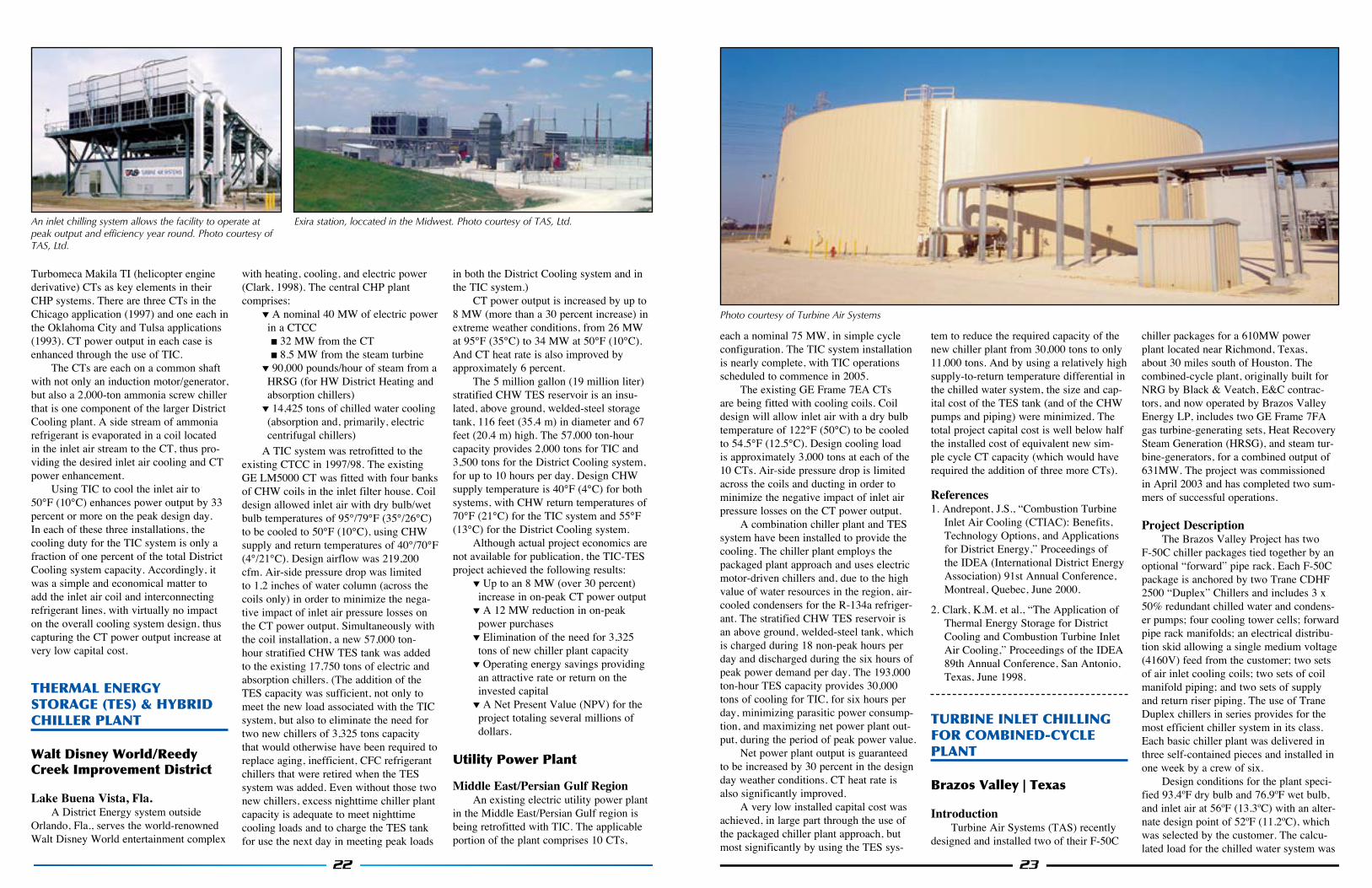
Photo courtesy of Turbine Air Systems
Turbomeca Makila TI (helicopter engine derivative) CTs as key elements in their CHP systems. There are three CTs in the Chicago application (1997) and one each in the Oklahoma City and Tulsa applications (1993). CT power output in each case is enhanced through the use of TIC.
The CTs are each on a common shaft with not only an induction motor/generator, but also a 2,000-ton ammonia screw chiller that is one component of the larger District Cooling plant. A side stream of ammonia refrigerant is evaporated in a coil located in the inlet air stream to the CT, thus pro-viding the desired inlet air cooling and CT power enhancement.
Using TIC to cool the inlet air to 50°F (10°C) enhances power output by 33 percent or more on the peak design day. In each of these three installations, the cooling duty for the TIC system is only a fraction of one percent of the total District Cooling system capacity. Accordingly, it was a simple and economical matter to add the inlet air coil and interconnecting refrigerant lines, with virtually no impact on the overall cooling system design, thus capturing the CT power output increase at very low capital cost.
THERMAL ENERGY STORAGE (TES) & HYBRID CHILLER PLANT
Walt Disney World/Reedy Creek Improvement District
Lake Buena Vista, Fla.A District Energy system outside
Orlando, Fla., serves the world-renowned Walt Disney World entertainment complex
with heating, cooling, and electric power (Clark, 1998). The central CHP plant comprises:
t A nominal 40 MW of electric power in a CTCCn 32 MW from the CTn 8.5 MW from the steam turbine
t 90,000 pounds/hour of steam from a HRSG (for HW District Heating and absorption chillers)
t 14,425 tons of chilled water cooling (absorption and, primarily, electric centrifugal chillers)
A TIC system was retrofitted to the existing CTCC in 1997/98. The existing GE LM5000 CT was fitted with four banks of CHW coils in the inlet filter house. Coil design allowed inlet air with dry bulb/wet bulb temperatures of 95°/79°F (35°/26°C) to be cooled to 50°F (10°C), using CHW supply and return temperatures of 40°/70°F (4°/21°C). Design airflow was 219,200 cfm. Air-side pressure drop was limited to 1.2 inches of water column (across the coils only) in order to minimize the nega-tive impact of inlet air pressure losses on the CT power output. Simultaneously with the coil installation, a new 57,000 ton-hour stratified CHW TES tank was added to the existing 17,750 tons of electric and absorption chillers. (The addition of the TES capacity was sufficient, not only to meet the new load associated with the TIC system, but also to eliminate the need for two new chillers of 3,325 tons capacity that would otherwise have been required to replace aging, inefficient, CFC refrigerant chillers that were retired when the TES system was added. Even without those two new chillers, excess nighttime chiller plant capacity is adequate to meet nighttime cooling loads and to charge the TES tank for use the next day in meeting peak loads
in both the District Cooling system and in the TIC system.)
CT power output is increased by up to 8 MW (more than a 30 percent increase) in extreme weather conditions, from 26 MW at 95°F (35°C) to 34 MW at 50°F (10°C). And CT heat rate is also improved by approximately 6 percent.
The 5 million gallon (19 million liter) stratified CHW TES reservoir is an insu-lated, above ground, welded-steel storage tank, 116 feet (35.4 m) in diameter and 67 feet (20.4 m) high. The 57,000 ton-hour capacity provides 2,000 tons for TIC and 3,500 tons for the District Cooling system, for up to 10 hours per day. Design CHW supply temperature is 40°F (4°C) for both systems, with CHW return temperatures of 70°F (21°C) for the TIC system and 55°F (13°C) for the District Cooling system.
Although actual project economics are not available for publication, the TIC-TES project achieved the following results:
t Up to an 8 MW (over 30 percent) increase in on-peak CT power output
t A 12 MW reduction in on-peak power purchases
t Elimination of the need for 3,325 tons of new chiller plant capacity
t Operating energy savings providing an attractive rate or return on the invested capital
t A Net Present Value (NPV) for the project totaling several millions of dollars.
Utility Power Plant
Middle East/Persian Gulf RegionAn existing electric utility power plant
in the Middle East/Persian Gulf region is being retrofitted with TIC. The applicable portion of the plant comprises 10 CTs,
Exira station, loccated in the Midwest. Photo courtesy of TAS, Ltd.An inlet chilling system allows the facility to operate at peak output and efficiency year round. Photo courtesy of TAS, Ltd.
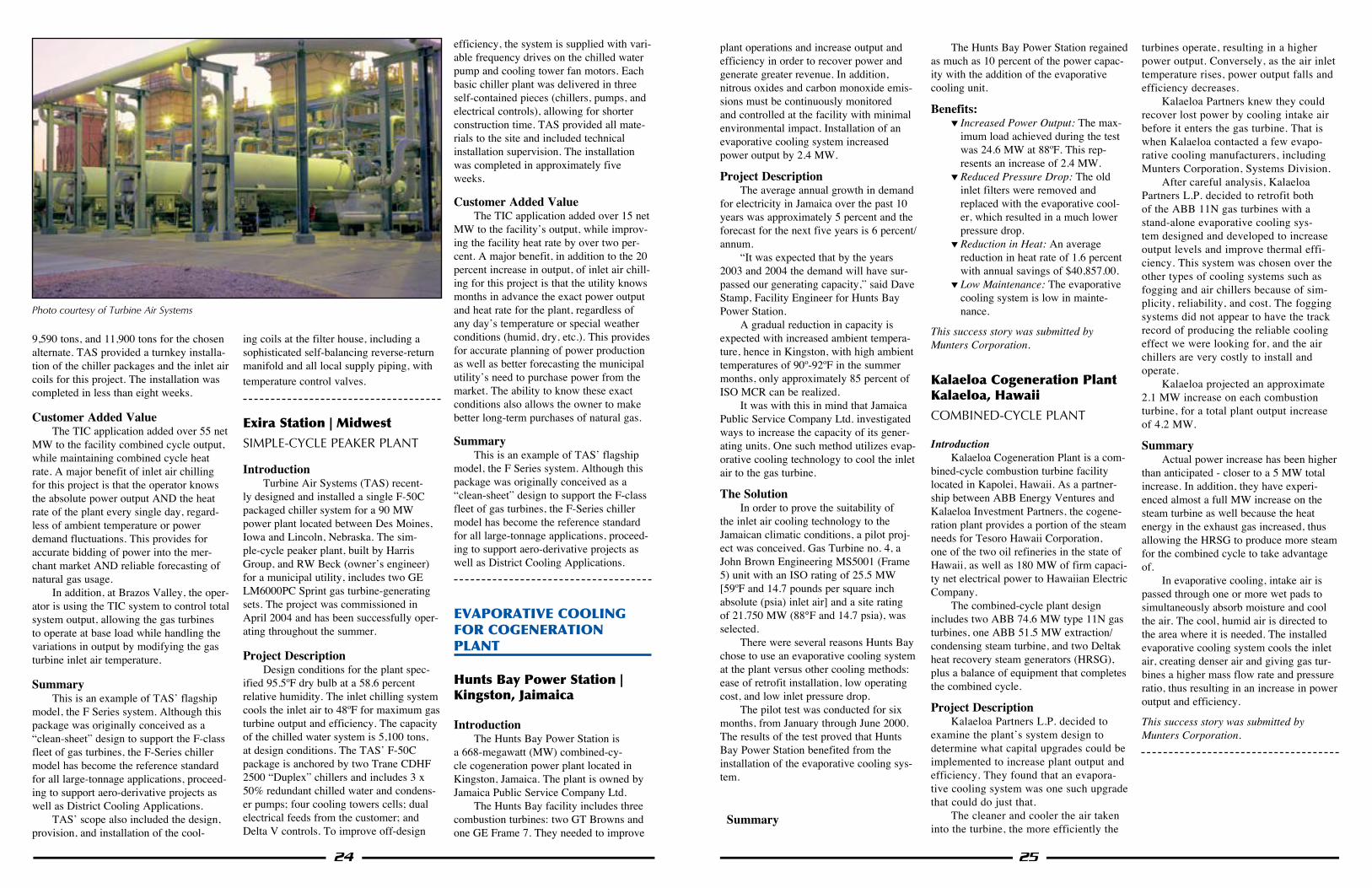
25
plant operations and increase output and efficiency in order to recover power and generate greater revenue. In addition, nitrous oxides and carbon monoxide emis-sions must be continuously monitored and controlled at the facility with minimal environmental impact. Installation of an evaporative cooling system increased power output by 2.4 MW.
Project DescriptionThe average annual growth in demand
for electricity in Jamaica over the past 10 years was approximately 5 percent and the forecast for the next five years is 6 percent/annum.
“It was expected that by the years 2003 and 2004 the demand will have sur-passed our generating capacity,” said Dave Stamp, Facility Engineer for Hunts Bay Power Station.
A gradual reduction in capacity is expected with increased ambient tempera-ture, hence in Kingston, with high ambient temperatures of 90º-92ºF in the summer months, only approximately 85 percent of ISO MCR can be realized.
It was with this in mind that Jamaica Public Service Company Ltd. investigated ways to increase the capacity of its gener-ating units. One such method utilizes evap-orative cooling technology to cool the inlet air to the gas turbine.
The SolutionIn order to prove the suitability of
the inlet air cooling technology to the Jamaican climatic conditions, a pilot proj-ect was conceived. Gas Turbine no. 4, a John Brown Engineering MS5001 (Frame 5) unit with an ISO rating of 25.5 MW [59ºF and 14.7 pounds per square inch absolute (psia) inlet air] and a site rating of 21.750 MW (88°F and 14.7 psia), was selected.
There were several reasons Hunts Bay chose to use an evaporative cooling system at the plant versus other cooling methods: ease of retrofit installation, low operating cost, and low inlet pressure drop.
The pilot test was conducted for six months, from January through June 2000. The results of the test proved that Hunts Bay Power Station benefited from the installation of the evaporative cooling sys-tem.
Summary
The Hunts Bay Power Station regained as much as 10 percent of the power capac-ity with the addition of the evaporative cooling unit.
Benefits: t Increased Power Output: The max-
imum load achieved during the test was 24.6 MW at 88ºF. This rep-resents an increase of 2.4 MW.
t Reduced Pressure Drop: The old inlet filters were removed and replaced with the evaporative cool-er, which resulted in a much lower pressure drop.
t Reduction in Heat: An average reduction in heat rate of 1.6 percent with annual savings of $40,857.00.
t Low Maintenance: The evaporative cooling system is low in mainte-nance.
This success story was submitted by Munters Corporation.
Kalaeloa Cogeneration Plant Kalaeloa, Hawaii
COMBINED-CYCLE PLANT
IntroductionKalaeloa Cogeneration Plant is a com-
bined-cycle combustion turbine facility located in Kapolei, Hawaii. As a partner-ship between ABB Energy Ventures and Kalaeloa Investment Partners, the cogene-ration plant provides a portion of the steam needs for Tesoro Hawaii Corporation, one of the two oil refineries in the state of Hawaii, as well as 180 MW of firm capaci-ty net electrical power to Hawaiian Electric Company.
The combined-cycle plant design includes two ABB 74.6 MW type 11N gas turbines, one ABB 51.5 MW extraction/condensing steam turbine, and two Deltak heat recovery steam generators (HRSG), plus a balance of equipment that completes the combined cycle.
Project DescriptionKalaeloa Partners L.P. decided to
examine the plant’s system design to determine what capital upgrades could be implemented to increase plant output and efficiency. They found that an evapora-tive cooling system was one such upgrade that could do just that.
The cleaner and cooler the air taken into the turbine, the more efficiently the
turbines operate, resulting in a higher power output. Conversely, as the air inlet temperature rises, power output falls and efficiency decreases.
Kalaeloa Partners knew they could recover lost power by cooling intake air before it enters the gas turbine. That is when Kalaeloa contacted a few evapo-rative cooling manufacturers, including Munters Corporation, Systems Division.
After careful analysis, Kalaeloa Partners L.P. decided to retrofit both of the ABB 11N gas turbines with a stand-alone evaporative cooling sys-tem designed and developed to increase output levels and improve thermal effi-ciency. This system was chosen over the other types of cooling systems such as fogging and air chillers because of sim-plicity, reliability, and cost. The fogging systems did not appear to have the track record of producing the reliable cooling effect we were looking for, and the air chillers are very costly to install and operate.
Kalaeloa projected an approximate 2.1 MW increase on each combustion turbine, for a total plant output increase of 4.2 MW.
SummaryActual power increase has been higher
than anticipated - closer to a 5 MW total increase. In addition, they have experi-enced almost a full MW increase on the steam turbine as well because the heat energy in the exhaust gas increased, thus allowing the HRSG to produce more steam for the combined cycle to take advantage of.
In evaporative cooling, intake air is passed through one or more wet pads to simultaneously absorb moisture and cool the air. The cool, humid air is directed to the area where it is needed. The installed evaporative cooling system cools the inlet air, creating denser air and giving gas tur-bines a higher mass flow rate and pressure ratio, thus resulting in an increase in power output and efficiency.
This success story was submitted by Munters Corporation.
24
9,590 tons, and 11,900 tons for the chosen alternate. TAS provided a turnkey installa-tion of the chiller packages and the inlet air coils for this project. The installation was completed in less than eight weeks.
Customer Added ValueThe TIC application added over 55 net
MW to the facility combined cycle output, while maintaining combined cycle heat rate. A major benefit of inlet air chilling for this project is that the operator knows the absolute power output AND the heat rate of the plant every single day, regard-less of ambient temperature or power demand fluctuations. This provides for accurate bidding of power into the mer-chant market AND reliable forecasting of natural gas usage.
In addition, at Brazos Valley, the oper-ator is using the TIC system to control total system output, allowing the gas turbines to operate at base load while handling the variations in output by modifying the gas turbine inlet air temperature.
SummaryThis is an example of TAS’ flagship
model, the F Series system. Although this package was originally conceived as a “clean-sheet” design to support the F-class fleet of gas turbines, the F-Series chiller model has become the reference standard for all large-tonnage applications, proceed-ing to support aero-derivative projects as well as District Cooling Applications.
TAS’ scope also included the design, provision, and installation of the cool-
ing coils at the filter house, including a sophisticated self-balancing reverse-return manifold and all local supply piping, with temperature control valves.
Exira Station | Midwest
SIMPLE-CYCLE PEAKER PLANT
IntroductionTurbine Air Systems (TAS) recent-
ly designed and installed a single F-50C packaged chiller system for a 90 MW power plant located between Des Moines, Iowa and Lincoln, Nebraska. The sim-ple-cycle peaker plant, built by Harris Group, and RW Beck (owner’s engineer) for a municipal utility, includes two GE LM6000PC Sprint gas turbine-generating sets. The project was commissioned in April 2004 and has been successfully oper-ating throughout the summer.
Project DescriptionDesign conditions for the plant spec-
ified 95.5ºF dry bulb at a 58.6 percent relative humidity. The inlet chilling system cools the inlet air to 48ºF for maximum gas turbine output and efficiency. The capacity of the chilled water system is 5,100 tons, at design conditions. The TAS’ F-50C package is anchored by two Trane CDHF 2500 “Duplex” chillers and includes 3 x 50% redundant chilled water and condens-er pumps; four cooling towers cells; dual electrical feeds from the customer; and Delta V controls. To improve off-design
efficiency, the system is supplied with vari-able frequency drives on the chilled water pump and cooling tower fan motors. Each basic chiller plant was delivered in three self-contained pieces (chillers, pumps, and electrical controls), allowing for shorter construction time. TAS provided all mate-rials to the site and included technical installation supervision. The installation was completed in approximately five weeks.
Customer Added ValueThe TIC application added over 15 net
MW to the facility’s output, while improv-ing the facility heat rate by over two per-cent. A major benefit, in addition to the 20 percent increase in output, of inlet air chill-ing for this project is that the utility knows months in advance the exact power output and heat rate for the plant, regardless of any day’s temperature or special weather conditions (humid, dry, etc.). This provides for accurate planning of power production as well as better forecasting the municipal utility’s need to purchase power from the market. The ability to know these exact conditions also allows the owner to make better long-term purchases of natural gas.
SummaryThis is an example of TAS’ flagship
model, the F Series system. Although this package was originally conceived as a “clean-sheet” design to support the F-class fleet of gas turbines, the F-Series chiller model has become the reference standard for all large-tonnage applications, proceed-ing to support aero-derivative projects as well as District Cooling Applications.
EVAPORATIVE COOLING FOR COGENERATION PLANT
Hunts Bay Power Station | Kingston, Jaimaica
IntroductionThe Hunts Bay Power Station is
a 668-megawatt (MW) combined-cy-cle cogeneration power plant located in Kingston, Jamaica. The plant is owned by Jamaica Public Service Company Ltd.
The Hunts Bay facility includes three combustion turbines: two GT Browns and one GE Frame 7. They needed to improve
Photo courtesy of Turbine Air Systems
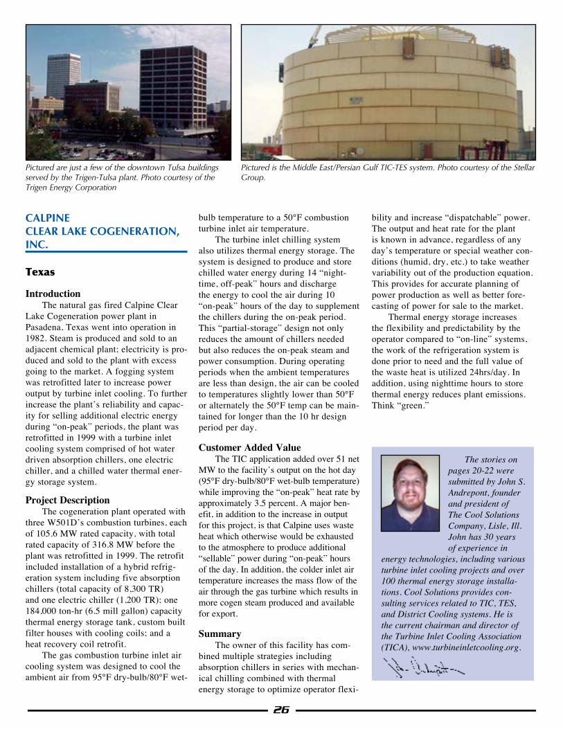
26
CALPINE CLEAR LAKE COGENERATION, INC.
Texas
IntroductionThe natural gas fired Calpine Clear
Lake Cogeneration power plant in Pasadena, Texas went into operation in 1982. Steam is produced and sold to an adjacent chemical plant; electricity is pro-duced and sold to the plant with excess going to the market. A fogging system was retrofitted later to increase power output by turbine inlet cooling. To further increase the plant’s reliability and capac-ity for selling additional electric energy during “on-peak” periods, the plant was retrofitted in 1999 with a turbine inlet cooling system comprised of hot water driven absorption chillers, one electric chiller, and a chilled water thermal ener-gy storage system.
Project DescriptionThe cogeneration plant operated with
three W501D’s combustion turbines, each of 105.6 MW rated capacity, with total rated capacity of 316.8 MW before the plant was retrofitted in 1999. The retrofit included installation of a hybrid refrig-eration system including five absorption chillers (total capacity of 8,300 TR) and one electric chiller (1,200 TR); one 184,000 ton-hr (6.5 mill gallon) capacity thermal energy storage tank, custom built filter houses with cooling coils; and a heat recovery coil retrofit.
The gas combustion turbine inlet air cooling system was designed to cool the ambient air from 95°F dry-bulb/80°F wet-
bulb temperature to a 50°F combustion turbine inlet air temperature.
The turbine inlet chilling system also utilizes thermal energy storage. The system is designed to produce and store chilled water energy during 14 “night-time, off-peak” hours and discharge the energy to cool the air during 10 “on-peak” hours of the day to supplement the chillers during the on-peak period. This “partial-storage” design not only reduces the amount of chillers needed but also reduces the on-peak steam and power consumption. During operating periods when the ambient temperatures are less than design, the air can be cooled to temperatures slightly lower than 50°F or alternately the 50°F temp can be main-tained for longer than the 10 hr design period per day.
Customer Added ValueThe TIC application added over 51 net
MW to the facility’s output on the hot day (95°F dry-bulb/80°F wet-bulb temperature) while improving the “on-peak” heat rate by approximately 3.5 percent. A major ben-efit, in addition to the increase in output for this project, is that Calpine uses waste heat which otherwise would be exhausted to the atmosphere to produce additional “sellable” power during “on-peak” hours of the day. In addition, the colder inlet air temperature increases the mass flow of the air through the gas turbine which results in more cogen steam produced and available for export.
SummaryThe owner of this facility has com-
bined multiple strategies including absorption chillers in series with mechan-ical chilling combined with thermal energy storage to optimize operator flexi-
bility and increase “dispatchable” power. The output and heat rate for the plant is known in advance, regardless of any day’s temperature or special weather con-ditions (humid, dry, etc.) to take weather variability out of the production equation. This provides for accurate planning of power production as well as better fore-casting of power for sale to the market.
Thermal energy storage increases the flexibility and predictability by the operator compared to “on-line” systems, the work of the refrigeration system is done prior to need and the full value of the waste heat is utilized 24hrs/day. In addition, using nighttime hours to store thermal energy reduces plant emissions. Think “green.”
The stories on pages 20-22 were submitted by John S. Andrepont, founder and president of The Cool Solutions Company, Lisle, Ill. John has 30 years of experience in
energy technologies, including various turbine inlet cooling projects and over 100 thermal energy storage installa-tions. Cool Solutions provides con-sulting services related to TIC, TES, and District Cooling systems. He is the current chairman and director of the Turbine Inlet Cooling Association (TICA), www.turbineinletcooling.org.
Pictured are just a few of the downtown Tulsa buildings served by the Trigen-Tulsa plant. Photo courtesy of the Trigen Energy Corporation
Pictured is the Middle East/Persian Gulf TIC-TES system. Photo courtesy of the Stellar Group.
C
M
Y
CM
MY
CY
CMY
K
GTIAC Energy-Tech Ad resize (output).pdf 1 17/8/15 2:30 PM
WWW.CALDWELLENERGY.COM
YOUR SINGLE-SOURCESOLUTION FORENERGY EFFICIENCY
C
M
Y
CM
MY
CY
CMY
K
Caldwell Energy_TICA 2015.pdf 1 8/17/2015 10:44:13 AM