twenty-second symposium (international) on …cantwell/difficult_to_find...twenty-second symposium...
TRANSCRIPT
Twenty-Second Symposium (International) on Combustion/The Combustion Institute, 1988/pp. 515-522
A N I N V E S T I G A T I O N O F T H E S T R U C T U R E O F A L A M I N A R
N O N - P R E M I X E D F L A M E I N A N U N S T E A D Y
V O R T I C A L F L O W
C. S. LEWIS, B. J. CANTWELL, U. VANDSBUBGER ANO C. T. BOWMAN
Stanford University Stanford, CA 94305
Although organized vortical motions have been observed in a variety of turbulent flames, there have been only a few experimental studies which have directly examined the structure of a flame imbedded in an unsteady vortical flow. In the present work, this problem is investigated using a laminar co-flowing jet flame in which a periodic vortical motion is in- duced by acoustic excitation of the fuel stream. A variety of optical planar imaging techniques are employed to define the instantaneous flame structure. Particle tracking is used to obtain the instantaneous two-dimensional velocity field. These measurements are combined to follow the evolution of the flame in the unsteady velocity field over one cycle of the excitation. The flame is observed to break up into a series of axisymmetric flamelets which convect and distort under the influence of buoyancy and the vortical flow. When the velocity field is viewed in a frame of reference moving with the flamelets the flow pattern is seen to consist of a pair of saddle points on either side of the flow centerline near the flame tip and a single saddle point on the centerline near the base of the flame. This latter saddle point is also evident in images of light scattered from TiO2 particles added to the fuel stream. Entrained fluid is fed into a large axisymmetric vortex surrounding the base of the flame. Because of heat release, the flame acts as an effective volume source in the flow. A high strain rate exists on the centerline at the base of the flame, and planar laser-induced fluorescence mea- surements of the concentration of OH show local extinction of the flame,
Introduction
Organized vortical motions have been observed in a variety of turbulent combustion flows. These observations have led to the deve lopment of a number of turbulent flame models which explicitly incorporate the interaction of the flame with these vortical structures. 1-6 However, there have been only a few experimental studies which have directly examined the structure of a flame interacting with an unsteady vortex. 7-12 In the present paper, the results of such a study are reported.
The specific configuration investigated is a lami- nar co-flowing jet flame in which a periodic vortical motion is induced by acoustic excitation of the fuel stream. A variety of optical planar imaging tech- niques are employed to define the instantaneous flame structure and particle tracking is used to ob- tain the instantaneous two-dimensional velocity field. By combining these measurements, the evolution of the flame in the unsteady velocity field is stud- ied.
Interpretation of the flow field makes use of to- pological methods which have been applied suc- cessfully to characterize the structure of nonreact-
ing flows. 13 This methodology provides a unified approach for characterizing various strain and ro- tation fields which can occur in turbulent flows and it provides an unambiguous language for describing unsteady flow patterns. Using simple topological rules as a guide one can often determine a com- plete flow field from incomplete data. However, flame topologies are more complex than in non-re- acting flows because of the presence of volume sources associated with heat release, and the utility of topological methods for reacting flows has not been previously investigated.
Experimental Apparatus and Procedure
Flow Facility:
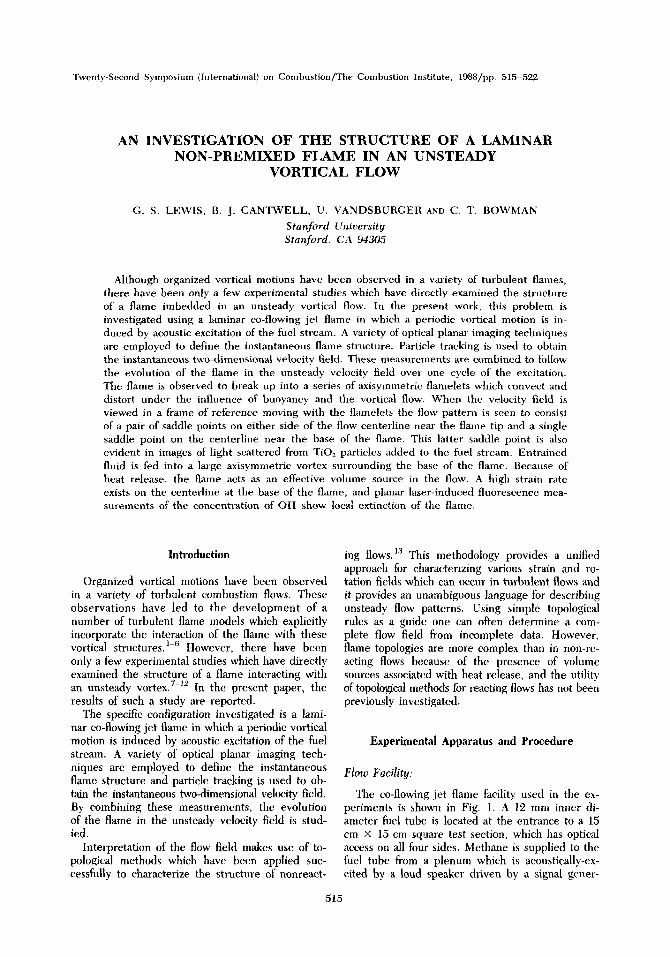
The co-flowing jet flame facility used in the ex- periments is shown in Fig. 1. A 12 mm inner di- ameter fuel tube is located at the entrance to a 15 em × 15 cm square test section, which has optical access on all four sides. Methane is supplied to the fuel tube from a plenum which is acoustically-ex- cited by a loud speaker driven by a signal gener-
515
516 TURBULENT COMBUSTION: FLAMES IN VORTICES
SEEOINGSYSTEM
FLOW METER
~ ORYER
CH4
~ow~-~'~T~--'-'~ ORIFICE I
SPEAKER L~
t SIGNAL GENERATOR
J~.~ PLENUM /% 16 HZ
FIG. 1. Schematic of burner facility.
ator. In the experiments reported here, the fuel jet enters as a fully-developed laminar flow. The mean jet exit velocity is 60 cm/s, and the uniform air flow velocity is also 60 cm/s. For these flow con- ditions, excitation of the fuel stream at 16 Hz, which is close to a natural instability frequency of the flame, produces a repeatable, periodic, axisymmetric flow field which permits measurements of flow quan- tities to be obtained in separate experiments. All of the optical imaging systems were phase-locked to the signal generator, thus allowing instantaneous measurements of the flame structure and velocity field at any specific time of the excitation cycle.
Flow Visualization Techniques:
Several flow visualization techniques were used to reveal features of the unsteady flame. These techniques are described in detail in Ref. 14, and only a brief discussion will be provided here. A conventional high-speed schlieren system was used to record the instantaneous density gradient field. The schlieren images provide information on the boundary between the hot combustion products and the cold ambient fluid. In the present work, light scattering from seed particles in the fuel jet has been used for visualization of the internal flow structure. In this technique, TiCI4 vapor is added to a dry fuel stream. The reaction of TiCIa with water vapor formed in the flame produces small, hydrated TiOz particles which may be visualized by light scatter- ing. 15 The amount of TIC14 used is extremely small and there is no noticeable effect of the particles, or the HCL that is produced, on the behavior of the flame. The optical and physical properties of these particles are such that they only visualize the colder parts of the flame. 16
The light source used for the light scattering measurements is a 20W pulsed copper vapor laser with a repetition rate of 6kHz and a pulse length of 30 ns. The laser beam is converted into a thin
vertical sheet and directed through the diametric center of the flame. Planar images of the scattered light, recorded on film at right angles to the laser sheet, provide information on the flow structure in- side the flame. To obtain information on the chem- ical structure of the flame, planar laser-induced fluorescence was used to obtain instantaneous two-dimensional maps of the concentration of OH molecules produced in the flame. In the case of non-premixed flames, OH is an intermediate spe- cies which exists at high concentrations only in a narrow region near the reaction zone, IV-Is and hence it may be used to locate the flame in the flow field and also to obtain an approximate measure of re- action zone thickness.
Particle Tracking Velocimetry:
In order to measure the instantaneous two-di- mensional velocity field in the flame, a particle tracking technique was developed based on a pulsed copper-vapor laser. The high pulse repetition rate and the capability to control the pulse rate make this laser an ideal tool for these measurements. Particle track images have been obtained that span approximately 10 diameters of the flow at eight phase angles of the excitation cycle. The technique is de- scribed in detail in Ref, 19.
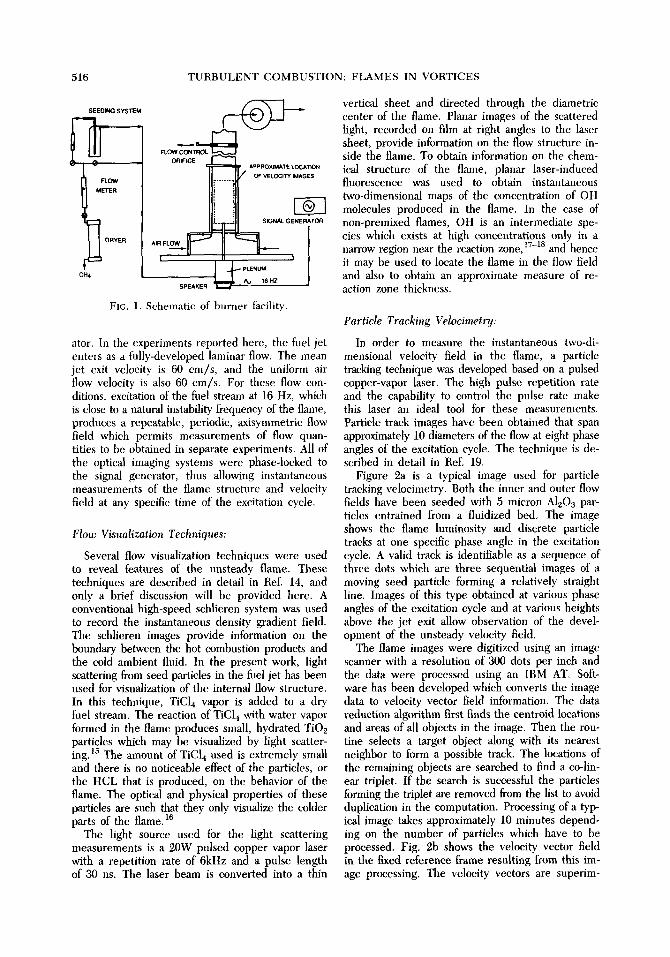
Figure 2a is a typical image used for particle tracking velocimetry. Both the inner and outer flow fields have been seeded with 5 micron AlzO3 par- ticles entrained from a fluidized bed. The image shows the flame luminosity and discrete particle tracks at one specific phase angle in the excitation cycle. A valid track is identifiable as a sequence of three dots which are three sequential images of a moving seed particle forming a relatively straight line. Images of this type obtained at various phase angles of the excitation cycle and at various heights above the jet exit allow observation of the devel- opment of the unsteady velocity field.
The flame images were digitized using an image scanner with a resolution of 300 dots per inch and the data were processed using an IBM AT. Soft- ware has been developed which converts the image data to velocity vector field information. The data reduction algorithm first finds the centroid locations and areas of all objects in the image. Then the rou- tine selects a target object along with its nearest neighbor to form a possible track. The locations of the remaining objects are searched to find a co-lin- ear triplet. If the search is successful the particles forming the triplet are removed from the list to avoid duplication in the computation. Processing of a typ- ical image takes approximately 10 minutes depend- ing on the number of particles which have to be processed, Fig. 2b shows the velocity vector field in the fixed reference frame resulting from this im- age processing. The velocity vectors are superim-
STRUCTURE OF LAMINAR NON-PREMIXED FLAME 517
t '
il
L t ~t:' t
I , t,
(a) (b)
FIC. 2. Illustration of the particle tracking technique. (a) Photograph showing soot luminousity and dis- crete tracks from AlzO3 seed particles. (b) Corresponding measured velocity vector field superimposed on photographically reversed luminous image.
posed on the reversed image of Fig. 2a to give a proper orientation. In a few instances obviously in- correct vectors are generated; these vectors are identified by visual inspection and eliminated in subsequent processing of the data. The technique is limited in several ways. Due to effects of ther- mophoresis and differential diffusion 19 very, few seed particles reach the hot regions of the flame. More- over the visibility of particles is poor in regions where soot luminosity overwhelms the particle scat- tering. This latter problem can be somewhat alle- viated by optical filtering although there is still sig- nificant flame radiation around the laser wavelengths. The soot luminosity can be removed almost com- pletely by adding nitrogen to the fuel however this significantly modifies the structure of the flame. In the measurements reported here the fuel is undi- luted methane.
Results
A sequence of images of Mie scattering from the TiO2 seed particles, soot luminosity and laser-in- duced fluorescence from OH at four phase angles during the excitation cycle are shown in Fig. 3. Al- though the OH images were not taken simulta- neously with the soot-Ti02 images, the repeatabil- ity of the flame was such that valid comparisons between the two images could be made. During
each cycle, a single large vortical structure forms and passes through the field of view. Two impor- tant features of the flow field revealed by these im- ages are: a large exterior ring vortex evident in both the soot luminosity images and the OH fluores- cence images which entrains ambient fluid into the flame, and an apparent stagnation point on the cen- terline, indicated by the Mie scattering images and by the velocity data presented below. Also evident in the Mie scattering images is a smaller counter- rotating vortex embedded in the inner flow. This inner vortex is believed to be formed near the fuel t ube exit. Under the influence of buoyancy, the maximum axial velocity near the fuel tube exit oc- curs in the flame zone giving rise to an initial ve- locity gradient consistent with the rotation sense of the inner vortex. By the time this vortex has been convected to the position indicated in the pictures the large exterior ring vortex is controlling the mo- tion. Similar observations of initial counterrotating vortex rings have been reported hy Eickhoff and Winandy in a jet flame using schlieren visualiza- tion. 20
The OH fluorescence images reveal the evolution of the flame in the unsteady flow. The OH images show that the flame zone is located outside of and approximately parallel to the luminous soot region. Another important feature of the OH images is the distortion of the flame by the unsteady flow leading to flame extinction on the centerliue (Fig. 3b) be-

518 T U R B U L E N T COMBUSTION: FLAMES IN VORTICES
' L
a b
c d
FIG. 3. Photographic sequence showing the evolution of the flame-flow s t ructure on the diametr ic plane of the jet. The images of soot luminosity and light scat tered from TiO2 seed particles in the fuel stream are super imposed on the cor responding OH concentrat ion field images. For phase angles: (a) 45 ° (b) 90 ° (c) 135 ° (d) 180 °.

STRUCTURE OF LAMINAR NON~PREMIXED FLAME 519
tween phase angles of 45 ° and 90 °. The OH images also provide an approximate measure of reaction zone thickness, which is 2 mm for the present condi- tions.
Measured velocity vector fields for phase loca- tions 45 ° and 90 ° . corresponding to the portion of the cycle when flame extinction occurs, are pre- sented in Fig. 4. This figure shows the velocity field over a region 90 mm long and 65 mm wide. The repeatability of the flame has been exploited to pro- duce the vector fields each of which is constructed from three separate photographs with a 30 mm × 65 mm field of view. Small discontinuities in the soot envelope can be seen at 18 em and 21 em cor- responding to the image boundaries. The velocities are shown relative to a frame of reference moving at a speed which is that of the lower edge of the flamelet. This velocity was determined to be 192 cm/s by measuring the displacement of the outside lower edge of the soot near the base of the flamelet from successive images. The absence of an arrow head indicates a velocity magnitude of 40 em/s or less, at which point the measurement errors in ra- dial and axial velocities become significant. These images indicate a large stagnant region inside the
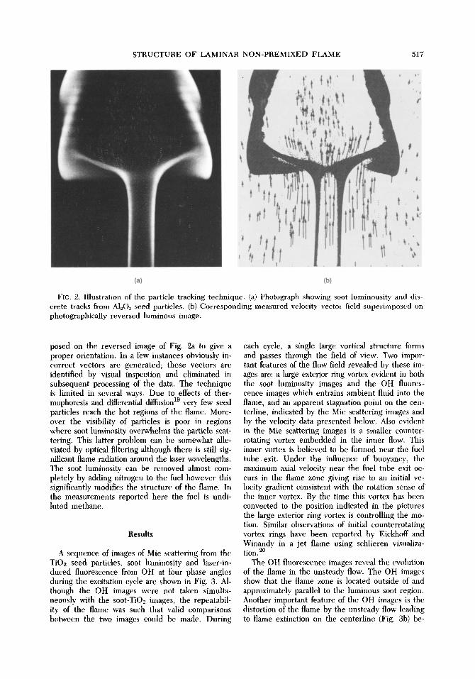
flame and a large toroidal vortex ring at the base of the flame which entrains ambient fluid into the flame. The vector fields suggest a very high strain rate at the base of the flame. To investigate this the centerline axial velocity and strain rate are plot- ted in Fig. 5. The plotted values in Fig. 5a rep- resent axial velocity data from 0 °, 45 °, and 90 °. Also shown in Fig. 5a is the velocity of the flamelet used in the moving frame plots of Fig. 4. The plot of axial strain rate in Fig. 5b is obtained by taking the derivative of the best fit of the velocity data of Fig. 5a. Since the operation of determining the strain rate involves only spatial derivatives, the data in Fig. 5b do not depend on the frame of reference.
Discussion
Combining the flame structure images, Fig. 3, with the velocity data, Fig. 4 and Fig. 5, provides a fairly complete description of the evolution of the flame. Near the flame tip at the top of the image (Fig. 4), the flow pattern, seen in a moving frame, consists of a pair of saddle points (stagnation points) on either side of the centerline with upward flow
i I ' ' ' I . . . . I ' ' ' I ' ' .
1 ' . 25
24
E
o o
18
17
14 0 2 4 6 0 ~ 2 4 6
R a d i a l L o c a t i o n - c m R a d i a l L o c a t i o n - c m
(a) (b )
FIG. 4. V e l o c i t y v e c t o r f i e lds in t h e m o v i n g f r a m e o f r e f e r e n c e s u p e r i m p o s e d o n t h e r e v e r s e d l u m i n o u s
image. The frame of reference speed is that of the flamelet lower edge. (a) 45 ° phase location (b) 90 ° phase location.
520 TURBULENT COMBUSTION: FLAMES IN VORTICES
6 0 0 ' ' ' ' I ' ' ' ' I ' ' ' ' I ' ' ' ' I . . . .
~p = Phase angle
3 0 0 (a )
.~ 200 . -- -- ~ -- .. -- --/4/-
1 0 0 t ~ = 0 o (p= 5 ~ q~= * " t y - '~
0 , , = , I , , , , I , , , , I , , , , I , , , , -
1 4 1 6 1 8 2 0 2 2 2 4
2 0 0 . . . . I . . . . I . . . . I . . . . I . . . .
Ul / " / \ " \ ' 1 ' " -200 (b)
/ ~ ,I ", i ~- .Z_30= ~ / ', i = o \ I ! ~ - - ~ = o *
-4oo ~--4o2 -383 - - ~ -46- . _ ~ = 9 0 o
- 6 0 0 , , , , I , , , , I , , , , I , , , , I , , , ,
1 4 1 6 1 8 2 0 2 2 2 4
A x i a l P o s i t i o n [ c r n ]
FIG. 5. Centerline axial velocity and strain rate profiles for 0 °, 45 °, and 90 ° phase angles. (a) cen- terline axial velocity. (b) centerline axial strain rate.
overall topology of the flow inside the flame is de- termined even though the velocities are too low for the flow to be resolved. The toroidal vortex sur- rounding the flame stem is represented as a pair of stable nodal points or foci. The flow pattern ob- served in this flame is similar to that deduced by Strawa s using one-dimensional eelocity measure- ments which were carried out much closer to the jet exit where the propagation speed of the flame is considerably lower. Some aspects of the vortex induced entrainment are similar to the modelling results of Karagozian and Manda 21 although their model did not account for the effects of heat re- lease. The possibility of having volume sources in the flow is a new element which does not arise in the application of phase plane techniques to con- stant temperature flows of the type considered by Perry and Chong.13
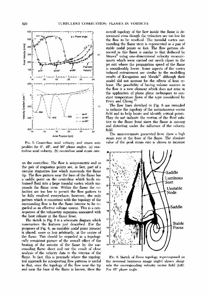
The flow lines sketched in Fig. 6 are intended to indicate the topology of the instantaneous vector field and to help locate and identify critical points. They do not indicate the motion of the fluid rela- tive to the flame front since the flame is moving and distorting under the influence of the velocity field.
The measurements presented here show a high strain rate at the base of the flame. The absolute value of the peak strain rate is shown to increase
on the centerline. The flow is axisymmetric and so the pair of stagnation points are, in fact, part of a circular stagnation line which surrounds the flame tip. The flow pattern near the base of the flame has a saddle point on the centerline which feeds en- trained fluid into a large toroidal vortex which sur- rounds the flame stem. Within the flame the ve- locities are too low to permit the flow pattern to be fully resolved everywhere; however, the only pattern which is consistent with the topology of the surrounding flow is for the flame interior to be re- garded as an effective volume source. This is a con- sequence of the volumetric expansion associated with the heat release at the flame front.
The sketch in Fig. 6 is a schematic diagram which summarizes the features just described. For the purposes of Fig. 6, an unstable nodal point (source) is placed, more or less arbitrarily, at the center of the flame. This should be regarded as a topologi- cally consistent picture of the overall effect of the heating of the interior of the flame by the sur- rounding flame sheet and not the result of close analysis of the velocity data in the interior of the flame. In fact, this is precisely where the topolog- ical approach for interpreting flow patterns is useful in that, once the topology of the flow near the tip and near the base of the flame is known, then the
FIG. 6. Sketch of flame topology superimposed on the reversed luminous image (right) shown along- side the corresponding velocity vector field (left). For 45 ° phase angle.
STRUCTURE OF LAMINAR NON-PREMIXED FLAME 521
from 304 sec -1 at the 0 ° phase angle to 402 sec -1 at the 45 ° angle then decrease slightly to 383 see -1 at the 90 ° angle. This region is similar in appear- ance to the rear stagnation region of a solid body translating downstream. The speed determined from the displacement of the negative peak in the strain rate in Fig. 5b is 307 cm/sec, which indicates that, as the flame evolves, the region of high strain pushes into the flame and decreases the size of the stag- nant region. In Fig. 2 the TiO2 particles are drawn into long filaments as the flame burns out, also in- dicating the collapse of the internal stagnant region. The experimental data of Tsuji 2~ and the calcula- tions of Dixon-Lewis et al. za indicate that the ex- tinction limit for a strained steady laminar meth- ane-air diffusion flame at the stagnation point of a porous cylinder occurs at strain rate levels of about 330-410 sec -1. This is consistent with the values of strain observed at the base of the present flame where the OH images reveal flame extinction along the centerline.
Conclusions
The results of the present study of the interac- tion of a laminar non-premixed flame with an un- steady vortical flow indicate that topological meth- ods may be usefully employed to characterize the structure of such a complex reacting flow. When viewed in a frame of reference moving with the flamelet the flow structure becomes apparent as a pattern of elementary flow features such as saddles and nodes which have been previously observed in non-reacting flows. The interior region of the flame is seen to be nearly stagnant, and the primary fluid mechanical role of the flame is that of a volume source. Relatively high local strain rates, produced by the vortical motion, are found in a region where flame extinction occurs. These observations suggest that volumetric expansion, associated with heat re- lease, and flame extinction should be included in models of flame-vortex interactions.
Acknowledgment
This research was supported by the Air Force Of- fice of Scientific Research under grant AF 84-0373 and by the National Science Foundation under grant 11869. We thank J. M. Seitzman for his assistance in obtaining the OH images.
REFERENCES
1. LIEW, S. K., BRAy, K. N. C., AND MOSS, J. B.: Comb. Sci. Tech. 27, 69 (1981).
2. GHONIEM, A. F., CHORIN, A. J., AND OPPEN-
HEIM, A. K.: Trans. Roy. Soc. A304, 325, (1982). 3. ASHURST, W. T. AND BARR, P. K.: Comb. Sci.
Tech. 34, 227 (1983). 4. McMuRTY, P. A., Jou, w . H., RILEY, J. J., AND
METCALFE, R. W.: AIAA J. 24, 962 (1986). 5. ORAN, E. S. AND BORIS, J. P.: Numerical Sim-
ulations of Reactive Flows, Elsevier, 1987. 6. PETERS, N.: Twenty-First Symposium (Inter-
national) on Combustion, p. 1231, The Com- bustion Institute, 1988.
7. STRAWA, A. W. AND CANTWEEL, B. J.: Phys. Fluids 28, 2317 (1985).
8. STRAWA, A. W.: An experimental investigation of the structure of an acoustically excited dif- fusion flame. Stanford PhD thesis and SU- DAAR 558, 1986.
9. YIP, T. W. G., STREHLOW, R. A. AND ORMSBEE, A. I.: Twentieth Symposium (International) on Combustion, p. 1655, The Combustion Insti- tute, 1985.
10. CATrOLICA, R. J. AND VOSEN, S. R.: Comb. Sci. Tech. 48, 77 (1986).
11. GUTMARK, E., PARR, T. P., PARR, D. M., AND SCt~ADOW, K. : "Planar Vortex Imaging of Vortex Dynamics in Flames," ASME Reprint 87-HT- 37, presented at the ASME National Heat Transfer Conference, Pittsburgh, August 1987.
12. HERTZBERG, J. R., NAMAZIAN, M. AND TALBOT, L.: Comb. Sci. Teeh. 38, 205 (1984).
13. PERRY, A. AND CHONG, M. S.: Ann. Rev. of Flnid Mech. 19, 125 (1987).
14. VANDSBURGER, U. , SEITZMANN, J. M. AND HAN- SON, R. K.: Comb. Sci. Tech., in press.
15. CHEN, L. D. AND ROQUEMORE, W. M.: Comb. Flame 66, 81 (1986).
16. WIT'ZE, P. O. A N D BARITAUD, T. A.: Particle Seeding for Mie Scattering Measurements in Combusting Flows, Sandia Natl. Labs Report SAND85-8912, (1986).
17. SMYTH, K. C., MILLER, J. H., DORFI~,tAN, R. C., MALLARD, W. G. , AND SANTORO, R. J.: Comb. Flame 62, 157 (1985).
18. RAE, E. C. AND HANSON, R. K.: Applied Op- tics, in press.
19. LEWIS, G. S., CANTWELL, B. J. AND LECUONA, A.: The use of particle tracking to obtain planar velocity measurements in an unsteady laminar diffusion flame. Western States Section / The Combustion Institute, Spring Meeting, Provo, Utah. Paper 87 - 35, 1987.
20. EICKHOFF, H. AND WINANDY, A.: Comb. Flame 60, 99 (1985).
21. KARAGOZIAN, A. R. AND MANDA, B. V. S.: Comb. Sei. Tech. 49, 185 (1986).
22. TswJI, H.: Prog. Energy Comb. Sci. 8, 93 (1982). 23. DIXON-LEwIS, G., et al. Twentieth Symposium
(International) on Combustion, p. 1893, The Combustion Institute, 1985.
522 T U R B U L E N T C O M B U S T I O N : F L A M E S IN V O R T I C E S
COMMENTS
R. H. Chen, Univ. of Michigan, USA. Have you ever come up with a quant i ta t ive relat ion be t ween flame extinct ion and local s train rates? If so what is your cr i ter ion of f lame ext inct ion? Since you ob- se rved f lame extinct ion w h e r e you th ink the stag- nat ion point is, local s t rain rate can easily be cal- culated.
Author's Reply. In r e sponse to your c o m m e n t concern ing calculation of local s train rates, we note that axial centerl ine strain rates, calculated from the velocity data, are p r e s e n t e d in Fig. 5 o f the paper . In this f igure, strain rates are p r e s e n t e d for phase
angles of 0, 45, and 90 degrees . T h e p re sence of a f a m e in t he flowfield is inferred by the p re sence of OH and we obse rve f lame extinct ion on the cen- terline be tween 45 and 90 degrees in a region where the peak calcula ted strain rates are 402 and 383 see -~, respect ively. This is cons i s ten t with refer- ences 22 and 23 of the pape r that have m e a s u r e d or p red ic ted f lame extinct ion for laminar opposed flow methane-ai r f lames in the range 350-400 sec ~. The work in these re fe rences is in a s teady flame and, hence , t he quant i ta t ive resul ts cannot be ap- pl ied exactly to the p r e sen t uns t eady case.