twepp 2011
DESCRIPTION
TWEPP 2011. The ALICE trigger Mari án Krivda On behalf of Trigger Project in the ALICE collaboration. Overview. Description of Central Trigger Processor (CTP) in ALICE experiment Performance – SMAQ plots, DQM Use of classes for beam gas correction - PowerPoint PPT PresentationTRANSCRIPT

26-30 Sep 2011, TWEPP 2011
Marián Krivda – University of Birmingham 1
TWEPP 2011
The ALICE trigger
Marián Krivda
On behalf of Trigger Project in the ALICE collaboration
Description of Central Trigger Processor (CTP) in ALICE experiment
Performance – SMAQ plots, DQM Use of classes for beam gas correction Configuration of CTP using Alice
Configuration Tool (ACT) Clock phase measurement and
adjustment using CORDE board Optical scope Firmware Upgrade CTP Upgrade plan
26-30 Sep 2011, TWEPP 2011
Marián Krivda – University of Birmingham 2
Overview
26-30 Sep 2011, TWEPP 2011
Marián Krivda – University of Birmingham 3
ALICE experiment
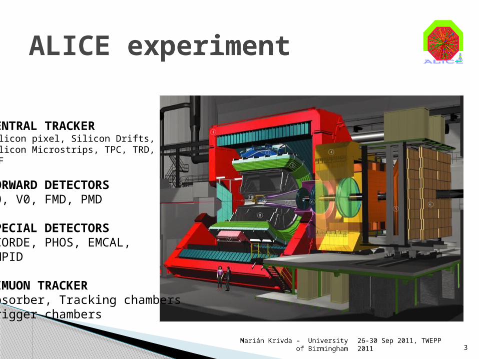
CENTRAL TRACKERSilicon pixel, Silicon Drifts, Silicon Microstrips, TPC, TRD,TOF
FORWARD DETECTORST0, V0, FMD, PMD
SPECIAL DETECTORSACORDE, PHOS, EMCAL,HMPID
DIMUON TRACKERAbsorber, Tracking chambersTrigger chambers
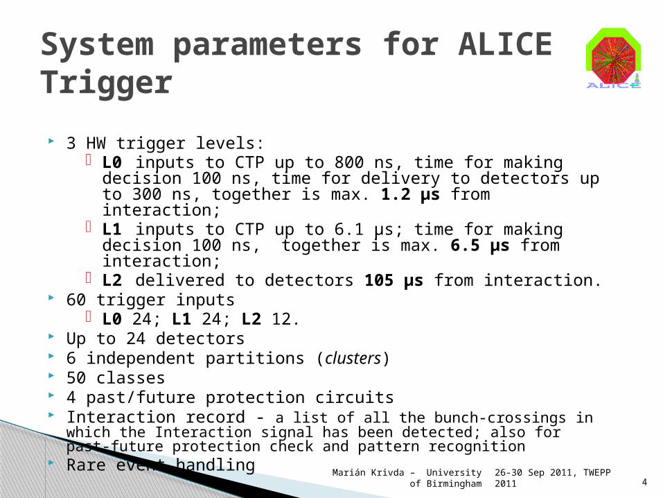
3 HW trigger levels: L0 inputs to CTP up to 800 ns, time for making decision 100 ns,
time for delivery to detectors up to 300 ns, together is max. 1.2 μs from interaction;
L1 inputs to CTP up to 6.1 μs; time for making decision 100 ns, together is max. 6.5 μs from interaction;
L2 delivered to detectors 105 μs from interaction. 60 trigger inputs
L0 24; L1 24; L2 12. Up to 24 detectors 6 independent partitions (clusters) 50 classes 4 past/future protection circuits Interaction record - a list of all the bunch-crossings in which the Interaction signal has
been detected; also for past-future protection check and pattern recognition Rare event handling
26-30 Sep 2011, TWEPP 2011
Marián Krivda – University of Birmingham 4
System parameters for ALICE Trigger
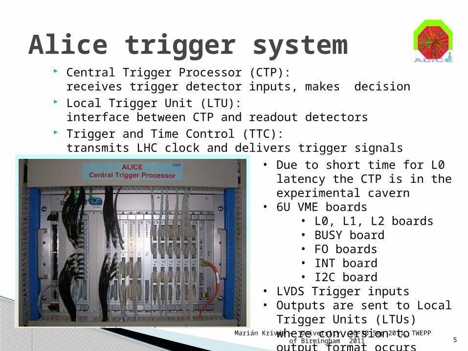
Central Trigger Processor (CTP):receives trigger detector inputs, makes decision
Local Trigger Unit (LTU):interface between CTP and readout detectors
Trigger and Time Control (TTC):transmits LHC clock and delivers trigger signals to detectors
26-30 Sep 2011, TWEPP 2011
Marián Krivda – University of Birmingham 5
Alice trigger system
• Due to short time for L0 latency the CTP is in the experimental cavern
• 6U VME boards• L0, L1, L2 boards• BUSY board• FO boards• INT board• I2C board
• LVDS Trigger inputs• Outputs are sent to Local Trigger
Units (LTUs) where conversion to output format occurs
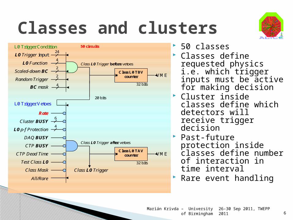
50 classes Classes define requested
physics i.e. which trigger inputs must be active for making decision
Cluster inside classes define which detectors will receive trigger decision
Past-future protection inside classes define number of interaction in time interval
Rare event handling
26-30 Sep 2011, TWEPP 2011
Marián Krivda – University of Birmingham 6
Classes and clusters
BC mask
Scaled-down BC
Random Trigger
4
2
2
Class L0 Trigger before vetoes
DAQ BUSY
6
CTP BUSY
CTP Dead Time
Test Class L0
Class Mask
32 bits
Class L0 TBV counter
20 bits
VME
L0 p-f Protection 4
Cluster BUSY
32 bits
Class L0 TAV counter VME
Class L0 Trigger after vetoes
Class L0 Trigger
L0 Trigger Condition
L0 Trigger Vetoes
All/Rare
50 circuits
L0 Trigger input
24
Rate
4
L0 Function
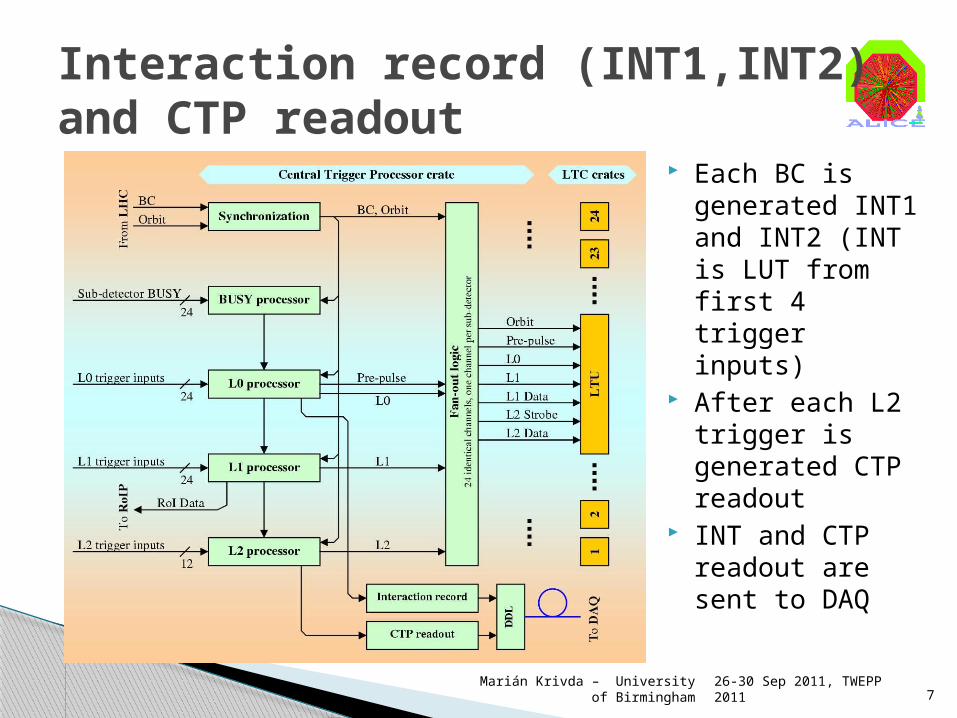
Each BC is generated INT1 and INT2 (INT is LUT from first 4 trigger inputs)
After each L2 trigger is generated CTP readout
INT and CTP readout are sent to DAQ
26-30 Sep 2011, TWEPP 2011
Marián Krivda – University of Birmingham 7
Interaction record (INT1,INT2)and CTP readout
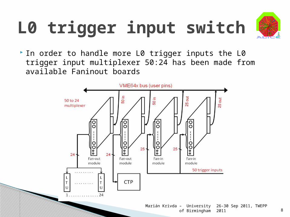
In order to handle more L0 trigger inputs the L0 trigger input multiplexer 50:24 has been made from available Faninout boards
26-30 Sep 2011, TWEPP 2011
Marián Krivda – University of Birmingham 8
L0 trigger input switch
26-30 Sep 2011, TWEPP 2011
Marián Krivda – University of Birmingham 9
SsM data Acquisition (SMAQ)
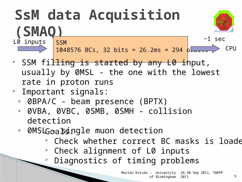
SSM1048576 BCs, 32 bits = 26.2ms = 294 orbits CPU
L0 inputs
SSM filling is started by any L0 input, usually by 0MSL - the one with the lowest rate in proton runs
Important signals:o 0BPA/C - beam presence (BPTX)o 0VBA, 0VBC, 0SMB, 0SMH - collision detectiono 0MSL - single muon detection
Goals: Check whether correct BC masks is loaded Check alignment of L0 inputs Diagnostics of timing problems
~1 sec
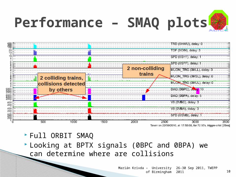
Full ORBIT SMAQ Looking at BPTX signals (0BPC and 0BPA) we can
determine where are collisions
26-30 Sep 2011, TWEPP 2011
Marián Krivda – University of Birmingham 10
Performance – SMAQ plots
26-30 Sep 2011, TWEPP 2011
Marián Krivda – University of Birmingham 11
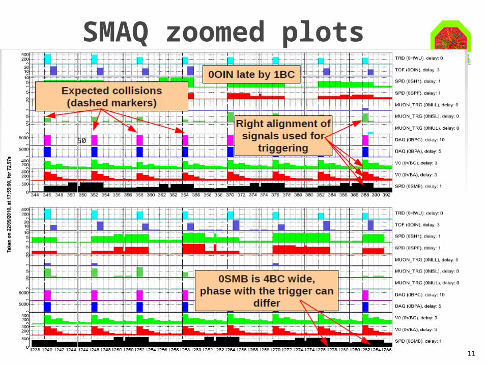
SMAQ zoomed plots
50
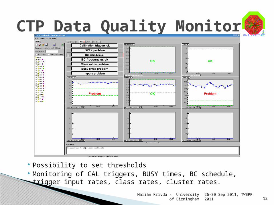
Possibility to set thresholds Monitoring of CAL triggers, BUSY times, BC schedule, trigger input
rates, class rates, cluster rates.
26-30 Sep 2011, TWEPP 2011
Marián Krivda – University of Birmingham 12
CTP Data Quality Monitor

Online screen
26-30 Sep 2011, TWEPP 2011
Marián Krivda – University of Birmingham 13
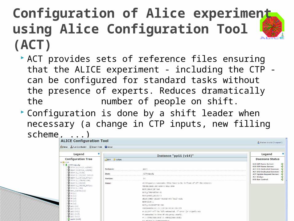
ACT provides sets of reference files ensuring that the ALICE experiment - including the CTP - can be configured for standard tasks without the presence of experts. Reduces dramatically the number of people on shift.
Configuration is done by a shift leader when necessary (a change in CTP inputs, new filling scheme, ...)
26-30 Sep 2011, TWEPP 2011
Marián Krivda – University of Birmingham 14
Configuration of Alice experimentusing Alice Configuration Tool (ACT)
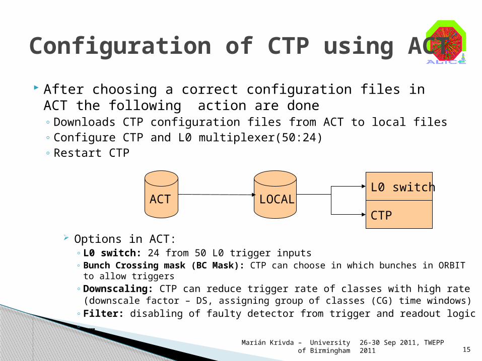
After choosing a correct configuration files in ACT the following action are done◦ Downloads CTP configuration files from ACT to local files◦ Configure CTP and L0 multiplexer(50:24)◦ Restart CTP
26-30 Sep 2011, TWEPP 2011
Marián Krivda – University of Birmingham 15
Configuration of CTP using ACT
CTP
L0 switchLOCALACT
Options in ACT:◦ L0 switch: 24 from 50 L0 trigger inputs◦ Bunch Crossing mask (BC Mask): CTP can choose in which bunches in ORBIT
to allow triggers◦ Downscaling: CTP can reduce trigger rate of classes with high rate
(downscale factor – DS, assigning group of classes (CG) time windows)◦ Filter: disabling of faulty detector from trigger and readout logic ◦ ……

Each class has associated BC mask:◦ B - colliding BCs◦ AC - BCs with bunches from A or C◦ E - BCs without bunch◦ D - cosmic during beam in empty BCs◦ I - isolated BCs i.e. colliding BCs separated by
min. 100 BCs In offline we are able to select Beam,
Beam-Gas-A, Beam-Gas-C and Empty versions of the trigger
26-30 Sep 2011, TWEPP 2011
Marián Krivda – University of Birmingham 16
Use of classes for background correction
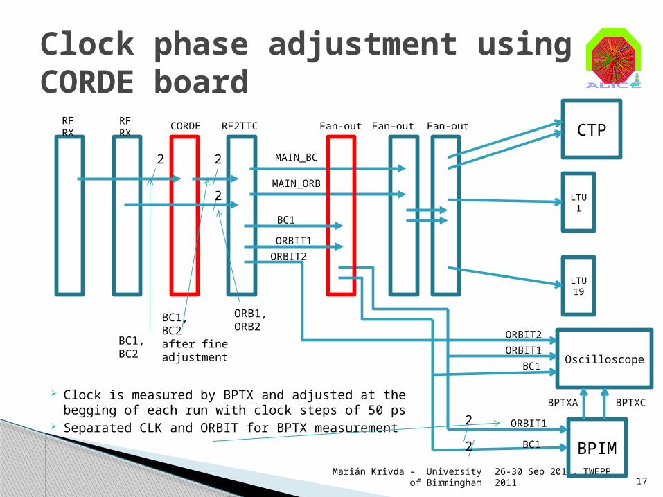
Clock is measured by BPTX and adjusted at the begging of each run with clock steps of 50 ps
Separated CLK and ORBIT for BPTX measurement
26-30 Sep 2011, TWEPP 2011
Marián Krivda – University of Birmingham 17
Clock phase adjustment using CORDE board
RF RX
RF RX
RF2TTCCORDE
2
Fan-out Fan-out
MAIN_BC
MAIN_ORB
BPIM
BC1
ORBIT1
BC1
BC1
CTP
LTU1
LTU19
ORBIT1
BC1,BC2
2
2
ORB1,ORB2
BC1,BC2after fineadjustment
Fan-out
2
2
OscilloscopeORBIT1
ORBIT2
BPTXA BPTXC
ORBIT2
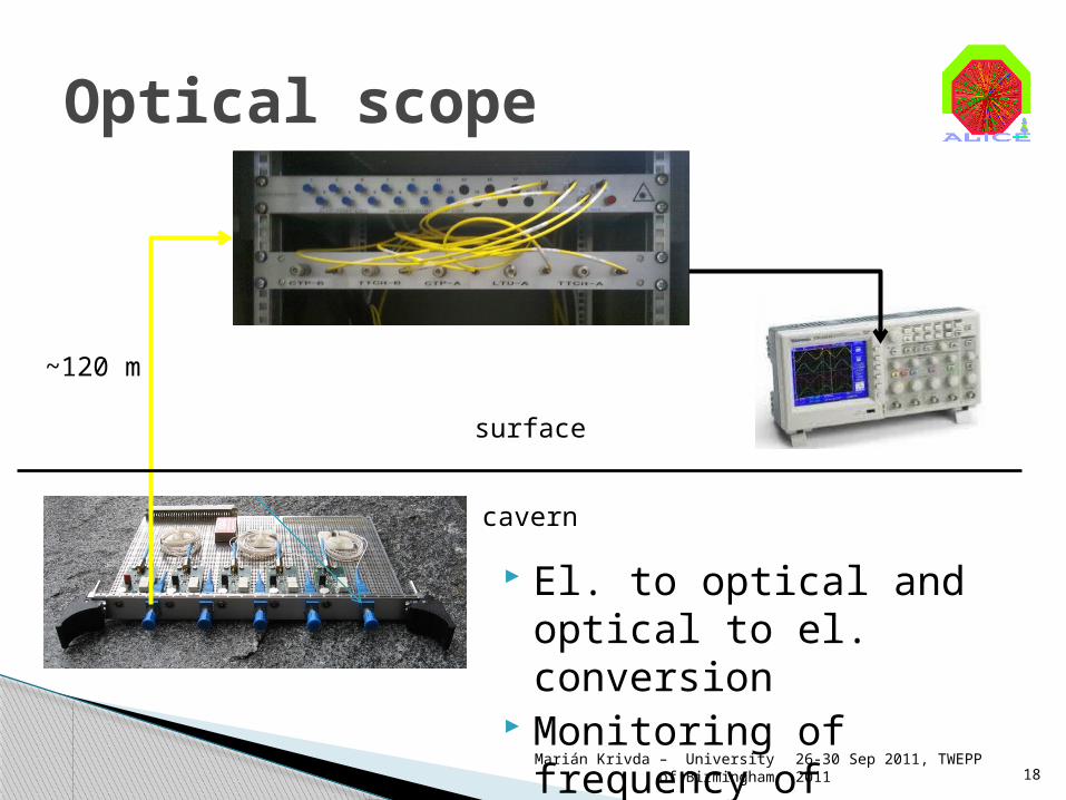
El. to optical and optical to el. conversion
Monitoring of frequency of signals in the cavern
Optical scope
26-30 Sep 2011, TWEPP 2011
Marián Krivda – University of Birmingham 18
cavern
surface
~120 m
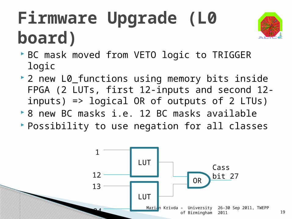
BC mask moved from VETO logic to TRIGGER logic
2 new L0_functions using memory bits inside FPGA (2 LUTs, first 12-inputs and second 12-inputs) => logical OR of outputs of 2 LTUs)
8 new BC masks i.e. 12 BC masks available Possibility to use negation for all classes
26-30 Sep 2011, TWEPP 2011
Marián Krivda – University of Birmingham 19
Firmware Upgrade (L0 board)
LUT
LUT
OR
Cassbit 27
1
12
13
24
Added timing option for interaction record to be sent to DAQ every 2 sec.
Changed synchronization of ORBIT counters as L2 trigger time extended to 105 µs
L2 delay extended to 13-bits Rate interlock units changed from ~0.82ms to
~0.1ms Rate period increases from 8 to 11 bits Added input for external ORBIT
26-30 Sep 2011, TWEPP 2011
Marián Krivda – University of Birmingham 20
Firmware Upgrade (INT board and LTU board)
Trigger input multiplexer (50:24) directly on L0 board – upgrade of L0 board with more trigger inputs and bigger FPGA
Implement GBT on LTU board Add more Interaction records – firmware
upgrade on L0 and INT board SMAQ plot for L1 inputs
26-30 Sep 2011, TWEPP 2011
Marián Krivda – University of Birmingham 21
Possible CTP Upgrade
Possibility to chose 24 from 50 L0 trigger inputs using L0 trigger switch
SMAQ plots and CTP DQM available to check correct performance
CTP is possible configure automatically from ACT at the begging of each run
Very sophisticated management of triggers into classes with associated BC masks
CORDE board used to adjust seasonal clock shift in steps of 50 ps
Optical scope available to check signals in the cavern Several firmware upgrades done for new requirements Possible CTP upgrade plans under discussion
26-30 Sep 2011, TWEPP 2011
Marián Krivda – University of Birmingham 22
Summary