typ 703030 typ 703031 typ 703032 - tematec.detematec.de/data/b70.3030.5gb.pdf · (relay...
TRANSCRIPT

Typ 703030Typ 703031Typ 703032
Compact microprocessorcontroller
B 70.3030.5Operating Manual
05.02

! Please read this Manual carefullybefore starting up the instrument.Keep the Manual in a place which isat all times accessible to all users.Please assist us to improve this Ma-nual where necessary.Your suggestions will be most wel-come.
! All necessary settings and, whereappropriate, alterations inside theinstrument are described in thisOperating Manual. If any difficultiesshould arise during start-up, you areasked not to carry out anymanipulations on the unit which arenot permitted. You could endangeryour rights under the instrumentwarranty! Please contact the nearestoffice or the main factory.
EWhen returning chassis, assembliesor components, the rules of EN 100 015“Protection of electrostaticallyendangered components” have tobe observed. Use only the appro-priate packaging material fortransport.
Please note that we can not be heldliable for any damage caused byESD (electrostatic discharges)


Contents
1 Introduction ........................................................................................ 5
1.1 Description .............................................................................................................. 51.2 Block diagram ......................................................................................................... 61.3 Typographical conventions ..................................................................................... 71.3.3 Presentation ............................................................................................................ 8
2 Identifying the instrument version .................................................... 9
3 Installation ......................................................................................... 11
3.1 Location and climatic conditions .......................................................................... 113.2 Dimensions ............................................................................................................ 113.2.1 Type 703030 .......................................................................................................... 113.2.2 Type 703031 .......................................................................................................... 123.2.3 Type 703032 .......................................................................................................... 123.2.4 Edge-to-edge mounting ........................................................................................ 133.3 Fitting in position ................................................................................................... 143.4 Cleaning the front panel ........................................................................................ 143.5 Removing the controller chassis ........................................................................... 14
4 Electrical connection ....................................................................... 15
4.1 Notes on installation .............................................................................................. 154.2 Connection diagram .............................................................................................. 16
5 Preparation ....................................................................................... 18
5.1 Display and keys ................................................................................................... 185.2 Operating mode and states ................................................................................... 185.3 Principle of operation ............................................................................................ 195.3.1 Levels .................................................................................................................... 195.3.2 Selecting the parameter set .................................................................................. 205.3.3 Input parameter ..................................................................................................... 205.3.4 Altering the configuration code ............................................................................. 20
6 Operation .......................................................................................... 21
6.1 Altering setpoints .................................................................................................. 216.2 Display controller output ....................................................................................... 216.3 Activate manual operation .................................................................................... 226.4 Start self-optimisation ........................................................................................... 226.5 Indicate software version and unit ........................................................................ 22
7 Parameters ........................................................................................ 23

Contents
8 Configuration .................................................................................... 25
8.1 C111 - Inputs ........................................................................................................ 258.2 C112 - Logic inputs, ramp function, overrange, unit/supply ................................ 268.3 C113 - Interface .................................................................................................... 278.4 C211 - Limit comparators ..................................................................................... 288.5 C212 - Controller type, manual operation inhibit, fuzzy function, output 31 ...... 298.6 C213- Functions of the outputs1 .......................................................................... 308.7 SCL - Standard signal scaling ............................................................................... 318.8 SCH - Standard signal scaling .............................................................................. 318.9 SPL - Setpoint limit ............................................................................................... 318.10 SPH - Setpoint limit ............................................................................................... 318.11 OFFS - Process value correction .......................................................................... 31
9 Optimisation ...................................................................................... 32
9.1 Optimisation .......................................................................................................... 329.1.1 Self-optimisation ................................................................................................... 329.1.2 Fuzzy logic ............................................................................................................ 329.2 Checking the optimisation .................................................................................... 33
10 Logic inputs ...................................................................................... 34
11 Ramp function .................................................................................. 35
12 Heater current indication/monitoring ............................................. 36
12.1 Heater current indication ....................................................................................... 3612.2 Heater current monitoring ..................................................................................... 36
13 Interface ............................................................................................ 37
14 Appendix ........................................................................................... 38
14.1 Technical Data ....................................................................................................... 3814.2 Limit comparator functions ................................................................................... 4014.3 Alarm messages .................................................................................................... 4214.4 External setpoint provision and setpoint priorities ................................................ 43
Programming the controller

1 Introduction
1.1 DescriptionThe compact microprocessor controllersType 703030, Type 703031 and Type 703032with the bezel sizes 96mm x 96mm and48mm x 96mm resp. and with a plug-in con-troller chassis, are particularly suitable fortemperature-controlled apparatus, laborato-ry equipment, plastics machinery, mechani-cal equipment etc. The controllers incorpo-rate two 4-digit 7-segment displays forprocess value (red) and setpoint (green). Du-ring programming the displays serve forcomments on the inputs. The controllers can be programmed as a sin-gle or double setpoint controller, modulatingor proportional controller with the usual con-troller structures. They also have two limitcomparators which can be assigned to theinput signals. There is a choice of eight diffe-rent limit comparator functions. A rampfunction with adjustable gradient, a start-upramp for the hot-channel method, as well asself-optimisation are available as standard.An interface (RS422/RS485), available as anoption, serves for integration into a data net-work. All connections are made through fa-ston tags 4.8mm x 0.8mm to DIN 46 244/A.
5

1 Introduction
1.2 Block diagram
6

1 Introduction
1.3 Typographical conventions
The signs for and are used inthis Manual under the following conditions:
V Danger This symbol is used when there may be dangerto personnel if the instruction is disregardedor not followed accurately.
" Warning This symbol is used when there may be da-mage to equipment or data if the instructionis disregarded or not followed accurately.
E Warning This symbol is used when precautions haveto be observed in handling components liableto be damaged by electrostatic discharges.
! Note This symbol is used if your special attention isdrawn to a remark.
# Reference This symbol refers to additional informationin other handbooks, chapters or sections.
abc1 Footnote Footnotes are notes which refer to certainpoints in the text.Footnotes consist of 2 parts:
Markings in the text and in the footnote text.
The markings in the text are arranged as con-tinuous raised numbers.
The footnote text (in smaller typeface) is pla-ced at the bottom of the page and starts witha number and a full stop.
H Action This symbol indicates that an action is beingdescribed.
The individual steps are indicated by thisasterisk, e.g.
H Press I key
7
1 Introduction
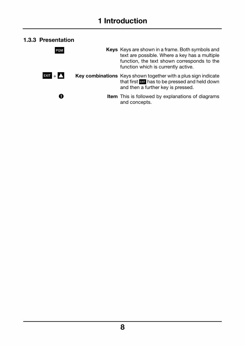
ys are shown in a frame. Both symbols andxt are possible. Where a key has a multiplenction, the text shown corresponds to thenction which is currently active.
ys shown together with a plus sign indicateat first X has to be pressed and held downd then a further key is pressed.
is is followed by explanations of diagramsd concepts.
1.3.3 Presentation
P Keys Ketefufu
X + I Key combinations Kethan
% Item Than
8

2 Identifying the instrument version
The label is affixed to the case. The typedesignation contains all the factory settings,such as controller function, signal inputs andextra Codes.
The Codes & are shown in sequence andseparated by a comma.
The supply must agree with the voltageshown on the label.
Delivery package:
– controller
– 2 mounting brackets
– seal
– Operating Manual B 70.3030.5
% Controller function Code
Single-setpoint controller, O function (relay de-energised above setpoint) 10
Single-setpoint controller, S function (relay de-energised below setpoint) 11
Double-setpoint controller(heating/cooling)switching/switching analogue/switching switching/analogue
3 . . 0. 1. 2
Modulating controller 40
Proportional controllerfalling characteristic (reverse acting)rising characteristic (direct acting)
5 .. 0. 1
9
Type designation
% ' ( ) * + &
703030/ .. - ... - ... - .. - ... - .. / ...
703031/ .. - ... - ... - .. - ... - .. / ...
703032/ .. - ... - ... - .. - ... - .. / ...
' Input 1 Code
Pt 100 001
Fe-Con J 040
Cu-Con U 041
Fe-Con L 042
NiCr-Ni K 043
Pt10Rh-Pt S 044
Pt13Rh-Pt R 045
Pt30Rh-Pt6Rh B 046
NiCrSi-NiSi N 048
Linearised transducers
0—20 mA 052
4—20 mA 053
0—10 V 063
2—10 V 070

2 Identifying the instrument version
( Input 2 Code
no function 000
Heater current indication0—50 mA AC
090
Stroke retransmission potentiometer
101
External setpoint0—20 mA4—20 mA 0—10 V2—10 V
11 . . . 1. . 2. . 7. . 8
) Functions of logic inputs
Logic input 1 Logic input 2 Code
no function no function 00
Key inhibit Parameter set switching 01
Level inhibit Parameter set switching 02
Ramp stop Parameter set switching 03
Setpoint selection Parameter set switching 04
Key inhibit Setpoint selection 05
Level inhibit Setpoint selection 06
Ramp stop Setpoint selection 07
Key inhibit Ramp stop 08
Level inhibit Ramp stop 09
* Output 3 Code
not used 000
Relay 101
Analogue output0—20 mA4—20 mA0—10 V2—10 V
001 005 065 070
+ Supply Code
93—263 V AC 48—63 Hz 01
20—53 V DC/AC 48—63 Hz 22
1
& Extra Codes (can be combined)
Code
no extra Code 000
Interface RS422/RS485 054
Logic outputs 4 and 5with 0/12 V output signal
015
UL approval 061
Up/down operation 050
Accessory
Current transformer (ratio 1:1000)size: 38 mm x 20 mm x 38 mmcable entry: 13 mm dia.Sales No. 70/00055040
0

3 Installation
Panel cut-out
mm inch
0.84.8
10.515.530.533.233.339.543.544+0.5
487379.38286.490.391.591.692+0.5
96105.8
0.0310.190.410.611.201.301.311.561.711.73+0.02
1.892.873.123.233.403.563.603.613.62+0.02
3.784.17
3.1 Location and climatic conditions
The instrument location should, as far aspossible, be free from shock and vibration.Stray electromagnetic fields. e.g. from motors,transformers etc., should be avoided. Theambient temperature at the location may bebetween 0 and +50 °C at a relative humiditynot exceeding 75 %.
3.2 Dimensions
3.2.1 Type 703030
11
3 Installation
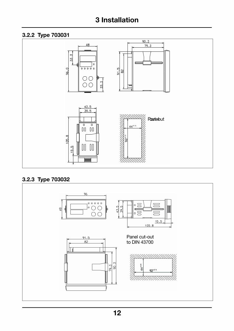
3.2.2 Type 703031
3.2.3 Type 703032
Panel cut-out
Panel cut-outto DIN 43700
12

3 Installation
3.2.4 Edge-to-edge mounting
13

3 Installation
release onboth sides
3.3 Fitting in positionH Place the seal supplied onto the housing
of the instrument.
H Insert the controller from the front into the panel cut-out.
H From the back of the panel slide the mount- ing brackets into the guides at the sides.The flat bracket faces must lie against the housing.
H Place the brackets against the rear of the panel and tighten them evenly with a screwdriver.
3.4 Cleaning the front panelThe front panel can be cleaned with the usu-al wash and rinse agents and detergents. Ithas a limited degree of resistance to organicsolvents (e.g. petrol, benzene, P1, xyleneand similar). Do not use any high-pressurecleaners.
3.5 Removing the controllerchassis
The controller chassis can be removed fromthe housing for servicing.
H With a tool, release front panel at the knurled areas (top and bottom, left and right) and pull out the controller chassis.
14

4 Electrical connection
4.1 Notes on installationK The choice of cable, the installation and
the electrical connection must conform tothe requirements of VDE 0100 “Regulati-ons on the installation of Power Circuitswith nominal voltages below 1000V” orthe appropriate local regulations.
K The electrical connection must only becarried out by properly qualified person-nel.
K If contact with live parts is possible whenworking on the instrument, it has to beisolated on both poles from the supply.
K A current limiting resistor interrupts thesupply circuit in case of a short-circuit.The external fuse of the supply should notbe rated above 1 A (slow). The load circuitmust be fused for the maximum relay cur-rent in order to prevent welding of the out-put relay contacts in case of an externalshort-circuit.
K Electromagnetic compatibility conformsto the standards and regulations listedunder Technical Data.
K Run input, output and supply lines sepa-rately and not parallel to each other.
K Sensor and interface lines should be ar-ranged as twisted and screened cables.Do not run them close to current-carryingcomponents or cables. Earth the screenat one end at the instrument on terminalTE.
vSection 14.1
1
K Earth the instrument at terminal TE to theearth conductor. This line must have atleast the same cross-section as the sup-ply lines. Earth lines should be run in astar layout to a common earth point whichis connected to the earth conductor of thesupply. Do not loop the earth connec-tions, i.e. do not run them from one instru-ment to another.
K Do not connect additional loads to thesupply terminals of the instrument.
K The instrument is not suitable for installa-tion in hazardous areas.
K Apart from faulty installation, there is apossibility of interference or damage tocontrolled processes due to incorrect set-tings on the controller (setpoint, data ofparameter and configuration levels, inter-nal adjustments). Safety devices indepen-dent of the controller, such as overpressu-re valves or temperature limiters/moni-tors, should always be provided andshould be capable of adjustment only byspecialist personnel. Please refer to theappropriate safety regulations in this con-nection. Since auto-tuning (self-optimisation)can not be expected to handle all possi-ble control loops, there is a theoreticalpossibility of unstable parameter settings.The resulting process value should there-fore be monitored for its stability.
K The signal inputs of the controller mustnot exceed a maximum potential of 30 VAC or 50 V DC against TE.
K All input and output lines that are not con-nected to the supply network must be laid out as shielded and twisted cables (do not run them in the vicinity of power cables or components). The shielding must be grounded to the earth potential on the instrument side.
5
4 Electrical connection
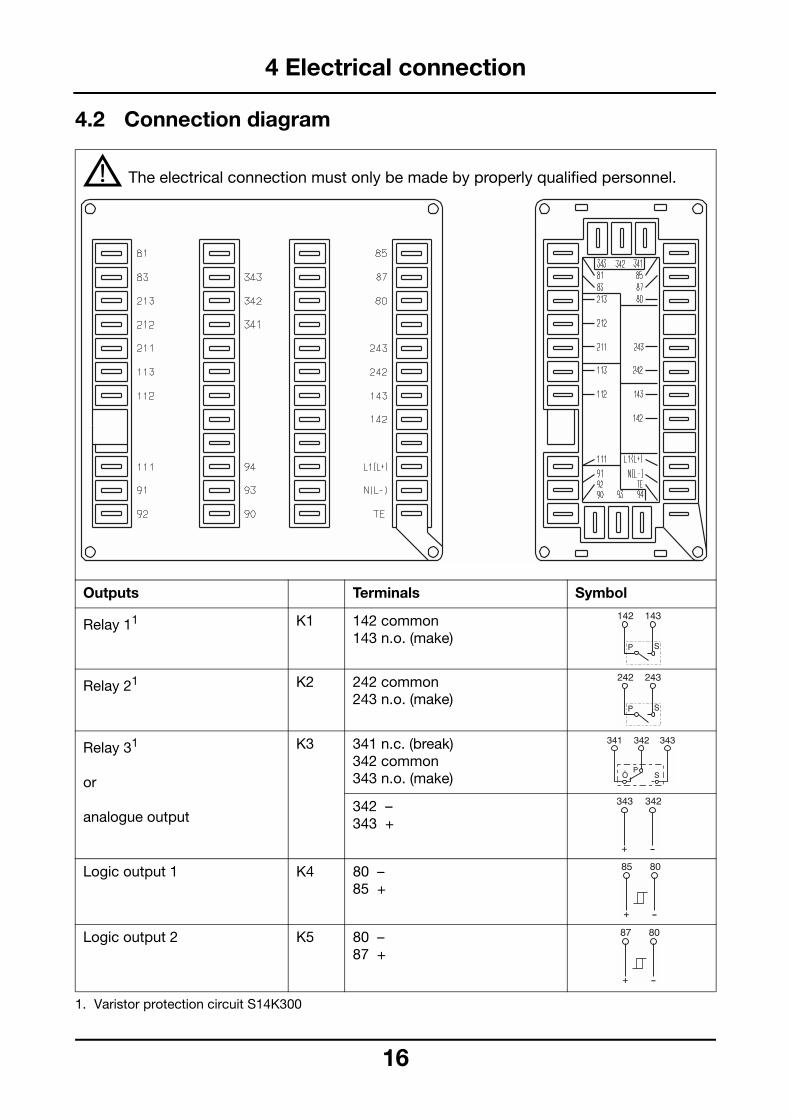
4.2 Connection diagram
V The electrical connection must only be made by properly qualified personnel.
Outputs Terminals Symbol
Relay 11
1. Varistor protection circuit S14K300
K1 142 common143 n.o. (make)
Relay 21 K2 242 common 243 n.o. (make)
Relay 31
or
analogue output
K3 341 n.c. (break)342 common343 n.o. (make)
342 –343 +
Logic output 1 K4 80 –85 +
Logic output 2 K5 80 –87 +
16

4 Electrical connection
Input 2 Symbol
-
-
-
211 S slider212 E end213 A start
211 + 212 –
211 + 212 –
211212
+ –
Receive Data
+ –
Send Data
/TxD+ /TxD–
Receive/Send Data
ralnical
DC:L+ L-
Signal inputs Input 1
Thermocouple 111 + 112 –
Resistance thermometerin 3-wire circuit
111112 113
Resistance thermometerin 2-wire circuitlead compensation viaprocess value correction (OFFS)
111 112113
Potentiometer
Current input 111 + 112 –
Voltage input 111 + 112 –
Heater current input0—50 mA AC
-
Serial interface RS422
RxD 91 RxD92 RxD
TxD 93 TxD 94 TxD
GND 90 GND
Serial interfaceRS485
RxD/ TxD
93 RxD94 RxD
GND 90 GND
Logic input 1 81 80
Logic input 2 83 80
Supply as on label AC/ DC
AC:L1 lineN neutTE tech
earth
17

5 Preparation
5.1 Display and keys
1. no function on analogue output K3
5.2 Operating mode and states
% process value display 7-segment display, red
' setpoint/heater current display 7-segment display, green
( decrement key to operate the controller
) PGM key
* ENTER key
+ increment key
& contact status indication1 to show the status of the five outputs
, LED for ramp function lights up when a ramp function is activated
Standard display the process value display shows the process value,the setpoint display shows the setpoint or the heater current
Initialising all displays light up, the setpoint display is flashing
Manual operation the process value display alternates between the process value and the word “Hand"; the setpoint display shows the controller output.
Ramp function the LED for ramp function lights up
Self-optimisation the word “tune" is flashing
Operating, parameters, configuration
the setpoint display shows the parameters of the different levels, the process value display shows the corresponding codes and values.
Alarm vSection 14.3
18

5 Preparation
5.3 Principle of operation
5.3.1 LevelsStandard displayFrom this status manual operation and self-optimisation can be activated.
The display shows the setpoint and the pro-cess value.
Operating levelHere the setpoints are input, the current con-troller output is indicated.
Parameter levelThe controller parameters and other settingsare programmed here.
Configuration levelThe basic functions of the controller are sethere.
Within the levels the P key is used toswitch over to the next parameter.
1. A change of level occurs only after all parameters of the individual levelshave been run through.
H If heater current monitoring isactivated, the heater current is shown on the setpoint display (value preceded by “H”
H It is possible to switch between two parameter sets. vSection 5.3.2 , 10
HThe display of the individual parame-ters depends on the controller type.
HChanges can only be made after cal-ling up the configuration level via theparameter y.0 of the parameter level.
HTime-outIf not operated, the controller returnsautomatically to standard displayafter approx. 30 sec.
19

5 Preparation
Parameter set 1
Parameter set 2
5.3.2 Selecting the parameter set
The controller has two parameter sets, bet-ween which it is possible to switch via a logicinput.Both parameter sets can be displayed forparameter setting.
H Change between the display of the para-meter sets with P when parameter Pb.1 is displayed(hold down key for at least 2 sec!)
The parameter set which is displayed is indi-cated by illuminated segments at parameterPb.1.
5.3.3 Input parameter
Parameters and setpoints can be input andchanged by continuous alteration of the va-lue. The speed of the alteration increaseswith the length of time in which the key isheld down.
H Increase value with I
H Decrease value with D
H Enter input with P
or
H abort input with X
After 2 sec the value which has been set isautomatically entered.The value changes only within the permittedvalue range.
5.3.4 Altering the configuration code
H Select digit with D(digit blinks!)
H Alter the value with I
H Enter the code with P
or
H abort the input with X
20

6 Operation
6.1 Altering setpoints Altering the active setpointin the standard display
H Alter the setpoint with D and I
According to the status of the setpoint swit-chover the active setpoint corresponds toSP1 or SP2 at the operating level.
Altering SP1 and SP2on the operating level
H Change to operating level with P
H Alter the setpoint SP1 with D and I
H Change to setpoint SP2 with P
H Alter the setpoint SP2 with D and I
H Return to standard display with Xor time-out
6.2 Display controller outputH Change to output display with 3x P
H Return to standard display with Xor time-out
21

6 Operation
6.3 Activate manual operationH Change to manual operation with X + I
(The process value display alternatesbetween the word "Hand" and theprocess value)
H Alter the output with I and D
H Return to automatic operation with X + I
6.4 Start self-optimisationH Start self-optimisation with X
(hold down key for at least 2 sec!)
H Abort with X(while self-optimistion is running.)
Self-optimisation is completed when thedisplay is no longer flashing "tune".
H Enter self-optimisation with X(hold down key for at least 2 sec!)(
6.5 Indicate software version and unit
H Indicate the software version and the unit of the process value with P + I (Hold down keys!)
Possible units are:°C, °F and % (for standard signals)
HOutput limitation is activated duringmanual operation. Manual operationis locked as factory-setting (C212).
HStarting self-optimisation is notpossible with activated level inhibitand in manual operation.
The activated parameter set is optimi-sed.
22

7 Parameters
Parameter Display Value range Fact.set. Notes
Setting limitcomparator 1
AL 1 –1999 to 9999 digit(–199.9 to 999.9 digit)1
0(0.0)1
vSection 8.4, 14.2
Setting limitcomparator 2
AL 2 –1999 to 9999 digit(–199.9 to 999.9 digit)1
0(0.0)1
Proportional band 1 Pb. 1 0 to 9999 digit(0.0 to 999.9 digit)1
0(0.0)1
Influences the P action of the controller.If Pb1,2=0 the controlstructure is ineffective.Proportional band 2 Pb. 2 0 to 9999 digit
(0.0 to 999.9 digit)1 0(0.0)1
Derivative time dt 0—9999 sec 80 sec Influences the D action of the controllerIf dt=0 the controller has no D action. On modulating controllers dt=rt/4 or 0 has to be entered.
Reset time rt 0—9999 sec 350 sec Influences the I action of the controller.If rt=0 the controller has noI action.
Stroke time tt 15—3000 sec 60 sec On modulating controllers; utilised stroke time range of valve.
Cycle time 1 Cy 1 1.0—999.9 sec 20.0 sec Duration of switching cycle on switching outputs.The cycle time should beselected so that the energy supply to the process isvirtually continuous while not subjecting the switchingelements to excessive wear.
Cycle time 2 Cy 2 1.0—999.9 sec 20.0 sec
Contact spacing db 0.0—100.0 digit 0.0 For switching double-setpoint controllers and modulating controllers.
1. for setting Pt100 or standard signal with one decimal place.vSection 8.1
23

7 Parameters
1.0 For controllers with Pb=0
1.0
0% Output at x=w
100% Example:analogue controller withfalling characteristic.–100%
0.6sec For adjusting the digital input filter
h or 0.0 vChapter 11
Fact.set. Notes
HOn controllers without controller structure (Pb=0)y.1 must be 100%and y.2= –100%
HOn double-setpointcontrollers without output limit y.2 = –100% must be set.
Differential 1 HyS.1 0.1—999.9 digit
Differential 2 HyS.2 0.1—999.9 digit
Working point y.0 –100 to +100%
Maximum output y.1 0—100%
Minimum output y.2 –100 to +100%
Filter timeconstant
dF 0.0—100.0 sec
Ramp slope rASd 0.0—999.9 digit/digit/min
Parameter Display Value range
24

8 Configuration
8.1 C111 - Inputs
Analogue input 1- sensor type1
Analogue input 1 - Standard signal2
Analogue input 2 - Function5
Analogue input 2 - Standard signal2
1. On the basic controller, it is possible to reconfigure freely between the sensor types Pt100, all thermo-couples and the standard signal 0—20mA/4—20mA (see second place from the left).
2. For the standard signal 0—10V/2—10V the hardware has to be reconfigured in the factory.3. The measurement of the heater current is shown on the setpoint display and identified by the prefix H.
The measurement range 0—50 mA AC is scaled to an indication range 0—50.0 A. The heater currentmonitoring of the measurement is implemented by configuring the limit comparators.v Section 8.4, 12.2
4. The input signal is scaled with the parameters SP.L and SP.H.v Section 8.9, 8.10
5. On the basic controller, it is possible to reconfigure freely between the functions “heater current display”and “external setpoint” (0—20mA/4—20mA). The functions “output retransmission” or “external setpoint”(0—10V/2—10V) require a hardware reconfiguration in the factory.
Pt 100 without decimal place 0 Pt 100 with decimal place 1 Fe-Con L 2 NiCr-Ni K 3 Pt10Rh-Pt S 4 Pt13Rh-Pt R 5 Pt30Rh-Pt6Rh B 6 Cu-Con U 7 NiCrSi-NiSi N 8 Fe-Con J 9 Standard signal without decimal place A Standard signal with decimal place b
0—20 mA / 0—10 V 0 4—20 mA / 2—10 V 1
no function 0 Heater current display3 (input: 0—50mA AC) 1 Output retransmission (input: potentiometer) 2 External setpoint4 (input: 0—20mA/4—20mA) 3
0—20 mA / 0—10 V 0 4—20 mA / 2—10 V 1
H The factory-set Codes are shown in the item boxes.An "X" identifies a setting which depends on the instrument version(see footnote.)
0000
25

8 Configuration
8.2 C112 - Logic inputs, ramp function, overrange, unit/supply
Function of the logic inputs
Ramp functions
Signal on overrange
Unit/Supply4
1. –100 % on double-setpoint controller.2. On modulating controller the position of the actuator is retained.3. The average value of the last outputs is retained.4. The supply frequency must agree with the setting.
Logic input 1 Logic input 2no function no function 0 Key inhibit Parameter set switching 1 Level inhibit Parameter set switching 2 Ramp stop Parameter set switching 3 Setpoint switching Parameter set switching 4 Key inhibit Setpoint switching 5 Level inhibit Setpoint switching 6 Ramp stop Setpoint switching 7 Key inhibit Ramp stop 8 Level inhibit Ramp stop 9
Ramp function OFF 0 Ramp function ON, slope °C/min 1 Ramp function ON, slope °C/h 2
Output 0 % Limit comparator OFF 0 Output 100 % Limit comparator OFF 1 Output 50 %1,2 Limit comparator OFF 2 Output unchanged3 Limit comparator OFF 3 Output 0 % Limit comparator ON 4 Output 100 % Limit comparator ON 5 Output 50%1,2 Limit comparator ON 6 Output unchanged3 Limit comparator ON 7
Degree Celsius 50 Hz 0 Degree Fahrenheit 50 Hz 1 Degree Celsius 60 Hz 2 Degree Fahrenheit 60 Hz 3
0000
26

8 Configuration
8.3 C113 - Interface
Instrument address
Parity
Baud rate
1. Address 0 is a "broadcast instruction"; see Interface Description B 70.3030.2
Address 01 0 0 Address 1 0 1 Address 2 0 2 Address 39 3 9
no parity MODbus protocol 0 odd parity MODbus protocol 1 even parity MODbus protocol 2 no parity Jbus protocol 3odd parity Jbus protocol 4even parity Jbus protocol 5
1200 baud 0 2400 baud 1 4800 baud 2 9600 baud 3
3010
27
8 Configuration
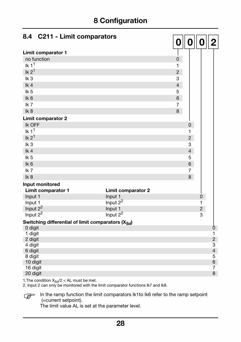
8.4 C211 - Limit comparators
Limit comparator 1
Limit comparator 2
Input monitored
Switching differential of limit comparators (XSd)
1.The condition XSd/2 < AL must be met.2. Input 2 can only be monitored with the limit comparator functions lk7 and lk8.
no function 0 lk 11 1 lk 21 2 lk 3 3 lk 4 4 lk 5 5 lk 6 6 lk 7 7 lk 8 8
lk OFF 0 lk 11 1 lk 21 2 lk 3 3 lk 4 4 lk 5 5 lk 6 6 lk 7 7 lk 8 8
Limit comparator 1 Limit comparator 2 Input 1 Input 1 0 Input 1 Input 22 1 Input 22 Input 1 2 Input 22 Input 22 3
0 digit 0 1 digit 1 2 digit 2 4 digit 3 6 digit 4 8 digit 5 10 digit 6 16 digit 7 20 digit 8
H In the ramp function the limit comparators lk1to lk6 refer to the ramp setpoint (=current setpoint).The limit value AL is set at the parameter level.
2000
28

8 Configuration
8.5 C212 - Controller type, manual operation inhibit, fuzzy function, output 31
Controller type2
Manual operation inhibit/fuzzy function
Output 3 - Standard signal3
Output 3 - Function3
1. Factory setting C212: 0000 on controllers without analogue output (K3);6001 on controllers with analogue output (K3)
2. When the controller type is changed, the controller parameters have to be checked (on double-setpointcontrollers set y.2 = -100%)
3. An analogue output ( output 3) must be available.
Controller type Controller output 1 Controller output 2Single-setpoint controller (heating)
O function – 0
Single-setpoint controller (cooling)
S function – 1
Double-setpoint controller(heating/cooling)
switching switching 2
Double-setpoint controller(heating/cooling)
fallingcharacteristic3
switching 3
Double-setpoint controller(heating/cooling)
switching rising characteristic3 4
Modulating controller open close 5 Proportional controller(heating)
falling characteristic3 – 6
Proportional controller(cooling)
rising characteristic3 – 7
Manual operation inhibited Fuzzy OFF 0 Manual operation enabled Fuzzy OFF 1 Manual operation inhibited Fuzzy ON 2 Manual operation enabled Fuzzy ON 3
0—20 mA 0 4—20 mA 1 0—10 V 2 2—10 V 3
no function 0 Controller output 1 1 Controller output 2 2 Limit comparator 1 3 Limit comparator 2 4
X00X
29

8 Configuration
8.6 C213- Functions of the outputs1
Output 1 - function (relay)
Output 2 - function (relay)
Output 4 - function (logic output)
Output 5 - function (logic output)
1. Factory setting C213: 1034 on controllers without analogue output (K3);3400 on controllers with analogue output (K3)
no function 0 Controller output 1 1 Controller output 2 2 Limit comparator 1 3 Limit comparator 2 4
no function 0 Controller output 1 1 Controller output 2 2 Limit comparator 1 3 Limit comparator 2 4
no function 0 Controller output 1 1 Controller output 2 2 Limit comparator 1 3 Limit comparator 2 4
no function 0 Controller output 1 1 Controller output 2 2 Limit comparator 1 3 Limit comparator 2 4
430X
30
8 Configuration
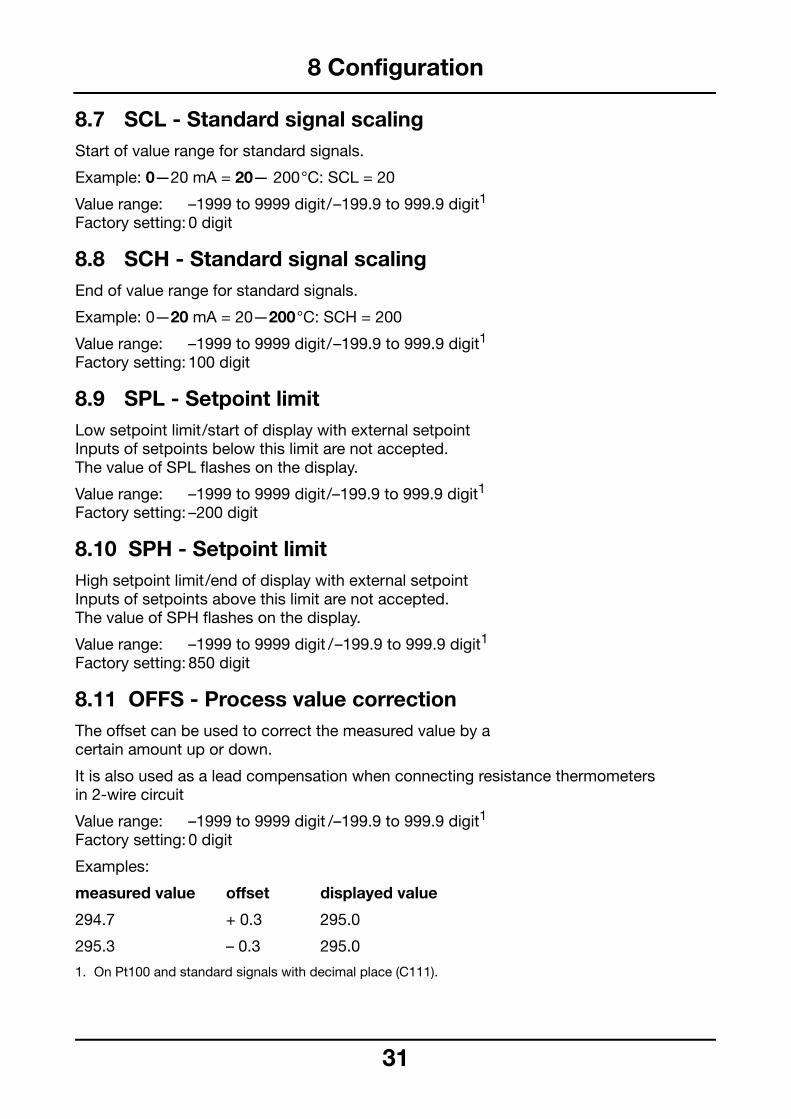
8.7 SCL - Standard signal scalingStart of value range for standard signals.
Example: 0—20 mA = 20— 200°C: SCL = 20
Value range: –1999 to 9999 digit/–199.9 to 999.9 digit1
Factory setting: 0 digit
8.8 SCH - Standard signal scalingEnd of value range for standard signals.
Example: 0—20 mA = 20—200°C: SCH = 200
Value range: –1999 to 9999 digit/–199.9 to 999.9 digit1
Factory setting: 100 digit
8.9 SPL - Setpoint limitLow setpoint limit/start of display with external setpointInputs of setpoints below this limit are not accepted.The value of SPL flashes on the display.
Value range: –1999 to 9999 digit/–199.9 to 999.9 digit1
Factory setting: –200 digit
8.10 SPH - Setpoint limitHigh setpoint limit/end of display with external setpointInputs of setpoints above this limit are not accepted.The value of SPH flashes on the display.
Value range: –1999 to 9999 digit /–199.9 to 999.9 digit1
Factory setting: 850 digit
8.11 OFFS - Process value correctionThe offset can be used to correct the measured value by a certain amount up or down.
It is also used as a lead compensation when connecting resistance thermometersin 2-wire circuit
Value range: –1999 to 9999 digit /–199.9 to 999.9 digit1
Factory setting: 0 digit
Examples:
measured value offset displayed value
294.7 + 0.3 295.0
295.3 – 0.3 295.0
1. On Pt100 and standard signals with decimal place (C111).
31

9 Optimisation
9.1 Optimisation
9.1.1 Self-optimisationThe self-optimisaton function (SO) is purelya software function and is incorporated inthe controller. SO investigates the reactionof the process to steps in controller outputusing a special procedure. Through an ex-tensive computing algorithm the processresponse (process value) is used to calcula-te the controller parameters for a PID or PIcontroller (set dt = 0!) and to store them. TheSO procedure can be repeated as manytimes as required.
The SO operates by two different methodswhich are selected automatically dependingon the dynamic condition of the process va-lue and its separation from the setpoint atthe start of optimisation. SO can be startedfrom any dynamic process value condition.
If there is a large separation between pro-cess value and setpoint when SO is activa-ted, a switching line is selected about whichthe process value performs a forced oscilla-tion during the SO procedure. The switchingline is chosen so that the process value doesnot exceed the setpoint, if possible.With a small deviation between process va-lue and setpoint, e.g. when the control loophas stabilised, a forced oscillation is produ-ced about the setpoint.The process data of the forced oscillationare recorded and used to calculate the con-troller parameters rt, dt, Pb.1, Pb.2, Cy1,Cy2, as well as a filter time constant optimalfor this process in order to filter the processvalue.
9.1.2 Fuzzy logicActivation of the fuzzy module can improvethe setpoint response and the disturbanceresponse of the controller.
HSelf-optimisation switches off the fuz-zy logic.
vSection 8.5
32

9 Optimisation
9.2 Checking the optimisationThe optimum adjustment of the controller tothe process can be checked by recording astart-up with the control loop closed.The diagrams below indicate possible incor-rect adjustments and their correction.
optimumadjustment
Pb too small
Pb too large
3
They are based on the control response of athird-order process for a PID controller. Theprocedure for adjusting the controller para-meters can also be applied to other pro-cesses.
A favourable value for dt is rt/4.
rt, dt too small
Cy too large
rt, dt too large
3
10 Logic inputs
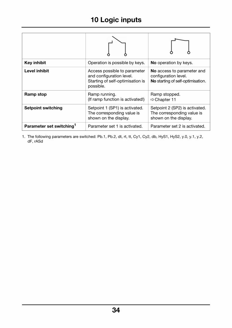
1. The following parameters are switched: Pb.1, Pb.2, dt, rt, tt, Cy1, Cy2, db, HyS1, HyS2, y.0, y.1, y.2,dF, rASd
Key inhibit Operation is possible by keys. No operation by keys.
Level inhibit Access possible to parameter and configuration level.Starting of self-optimisation is possible.
No access to parameter and configuration level.No starting of self-optimisation.
Ramp stop Ramp running.(If ramp function is activated!)
Ramp stopped. vChapter 11
Setpoint switching Setpoint 1 (SP1) is activated. The corresponding value is shown on the display.
Setpoint 2 (SP2) is activated. The corresponding value is shown on the display.
Parameter set switching1 Parameter set 1 is activated. Parameter set 2 is activated.
34

11 Ramp function
Change of ramp slope
Change of ramp end point
Change of ramp setpoint
Setpoint with ramp stop
Both a rising and a falling ramp function canbe implemented. As soon as power is swit-ched on, the current process value is setequal to the ramp setpoint and the setpointruns according to the selected slope untilthe ramp end point SP is reached. The rampend point is entered at the setpoint input.The ramp end point is now the current set-point. When the ramp end point is reached,then WR = SP.WR = ramp setpoint SP= ramp end pointtx = instant of alteration
Action on sensor breakOn sensor break the ramp function is inter-rupted. The outputs act as for overrange orunderrange (can be configured). When thefault has been rectified, the controller ac-cepts the current process value as ramp set-point and continues the ramp function.
Action on supply failureWhen the supply is restored, the controlleraccepts the current process value as rampsetpoint and continues the ramp functionwith the set parameters.
Action during manual operationDuring manual operation the ramp functionis interrupted. After changing to automaticoperation the current process value is ac-cepted as the ramp setpoint and the rampfunction continues with the set parameters.
Ramp stop Activating the ramp stop via a logic inputholds up the ramp function. The setpointdisplay is flashing. After the ramp stop hasbeen de-activated, the ramp function conti-nues with the ramp setpoint at the time ofthe ramp stop.
Ramp restartThe ramp can be restarted with the key com-bination X + I.
35

12 Heater current indication/monitoring
12.1 Heater current indicationUsing a current transformer (ratio 1:1000) itis possible to measure and indicate the heatercurrent via input 2.
The input signal range is 0—50mA AC. Theinput signal is scaled for an indication rangeof 0—50.0 A.
With appropriate configuration (configurati-on code C111= XX10), the measured value isshown on the bottom display preceded by theletter "H".
The measurement of the heater currenttakes place while the heating contact is clo-sed. When the heating contact is opened,the leakage current is measured and indica-ted with a delay of 5 sec.
12.2 Heater current monitoringThe heater current can be monitored foroverlimit and/or underlimit using the limitcomparators (function lk7 and lk8).
Configuring heater current monitoring alsoprovides leakage current monitoring. This isdone internally using a limit comparator withfunction lk7, a differential of 0 and a limit cor-responding to 1 percent of that configuredfor heater current monitoring.
36

13 Interface
The controller can be integrated into a datanetwork through the interface. The followingapplications can be realised, e.g.:
- process visualisation- system control- report
The bus system is designed according to themaster-slave principle. A master computercan control up to 31 controllers and instru-ments (slaves). The interface is a serial inter-face with the standards RS422 or RS485.
The following data protocols are possible:
- MODbus protocol- Jbus protocol
H Interface descriptionB 70.3030.2
H Retrofitting can only be performed inthe factory.
37

14 Appendix
14.1 Technical DataInput 1The change between Pt100, thermocouples,0 — 20mA and 4 — 20mA can be configu-red in the software.Voltage inputs 0(2) — 10 V require a hard-ware alteration in the factory.
Controller for use with resistance thermometers
InputPt100 in 2-wire or 3-wire circuit
Control range–199.9 to +850.0°C–200 to +850°C
Lead resistance: 30 Ω max.
Lead compensationnot required with 3-wire circuit. When used with a resistance thermometer in2-wire circuit, lead compensation can beprovided by an external compensationresistor (Rcomp = Rline). In addition, the leadresistance can be compensated in thesoftware through process value correction.
Controller for use with thermocouples
Temperature compensation: internal
Controller for use with linearisedtransducers with standard signal
Display with or without decimal place
Type Range Fe-Con L –200 to + 900°C Fe-Con J –200 to +1200°C NiCr-Ni K –200 to +1372°C Cu-Con U –200 to + 600°C NiCrSi-NiSi N –100 to +1300°C Pt10Rh-Pt S 0 to +1768°C Pt13Rh-Pt R 0 to +1768°C Pt30Rh-Pt6Rh B 0 to +1820°C
Signals Internal resistance Rivoltage drop ∆Ue
0(2) — 10 V Ri = 500 kΩ
0(4) — 20 mA ∆Ue = 1V
3
Input 2Change between 0(4) — 20mA (external set-point) and 0 — 50mA AC (heater currentmonitoring) can be configured in the soft-ware.Voltage inputs 0(2) — 10 V and potentiome-ter input require a hardware alteration in thefactory.
Controller for use with linearisedtransducers with standard signal
Display with or without decimal place
Controller for use with potentiometerR = 100 Ω to 10 kΩ
Controller for use with current transformer(heater current monitoring)Connection through current transformer(transformer ratio 1:1000)0 — 50 mA AC sinusoidalScaling: 0 — 50.0 A
Outputs2 relay outputs and 2 logic outputs areavailable as standard, 1 relay or analogueoutput as option.
1. Relay outputs K1/K2n.o. (make) contactRating : 3 A 250 V AC on resistive loadContact life: more than 5x10⁵ operations at rated load.
2. Relay output K3changeover contactRating: 3 A 250 V AC on resistive loadContact life: more than 5x10⁵ operations at rated load.
3. Logic outputs K4/K50/5 V Rload more than 250 Ω0/12 V Rload more than 650 Ω
Signals Internal resistance Rivoltage drop ∆Ue
0(2) — 10 V Ri = 500 kΩ
0(4) — 20 mA ∆Ue = 1 V
8

14 Appendix
4. Analogue output K30(2) — 10 V Rload more than 500 Ω0(4) — 20 mA Rload less than 500 Ωisolation to the inputs:∆U less than 30 V AC ∆U less than 50 V DC
General controller data
Controller typeCan be configured as single or double set-point controller, modulating or proportionalcontroller
A/D converter: resolution better than 15 bit
Sampling time: 210 msec
These values include the linearisation to-lerances.
* on Pt30Rh-Pt6Rh B within the range 300 — 1820°C
Measurement circuit monitoring
X = recognised – = not recognised
The outputs move to a defined status.
Data protection: EEPROM
Measurementaccuracy
Ambienttemperature error
when used with resistance thermometers 0.05% or better 25 ppm max. per °C when used with thermocouples within theworking range 0.25% or better* 100 ppm max. per °C when used with linearised transducers withstandard signal0.1% or better 100 ppm max. per °C
Transducer Sensor break Short-circuitresistancethermometer
X X
thermocouples X –0 — 10V – –2 — 10V X X0 —20mA – –4 —20mA X X
3
Supply 93 — 263 V AC 48 — 63 Hz or 20 — 53 V DC/AC 48 — 63 Hz
Power rating: 8 VA approx.
Electrical connectionthrough faston tabs to DIN 46 244/A, 4.8 mm x 0.8 mm
Permitted ambient temperature range 0 to +50°C
Permitted storage temperature range–40 to +70°C
Climatic conditionsrelative humidity not to exceed 75%,no condensation
Protection to EN 60 529 front IP 65 back IP 20
Electrical safetyto EN 61 010Class 2 clearance and creepage distances for- overvoltage category 2- pollution degree 2
Electromagnetic compatibilityEN 61 326Interference emission: Class BImmunity to interference: Industrial requirements
Housingfor flush panel mounting to DIN 43 700,in conductive plastic, base material ABS,with plug-in controller chassis
Operating position unrestricted
Weight 430 g approx.
Interface RS422/RS485isolated
Baud rate: 1200 — 9600 baud
Protocol: MODbus /Jbus
Instrument address: 1 — 31
9

14 Appendix
14.2 Limit comparatorfunctions
Function lk1 Window function: the output is ON when themeasurement is within a certain range aboutthe setpoint (w).Example: w = 200°C, AL = 20, XSd = 10 Measurement increasing: relay is energisedat 185°C and de-energised at 225°C. Measurement decreasing: relay is energisedat 215°C and de-energised at 175 °C.
Function lk2 as lk1, but relay function reversed
Function lk3 low alarm Function: output is OFF when measurementis below (setpoint–limit value)Example: w = 200°C, AL = 20, XSd = 10 Measurement increasing:relay is energised at 185°C.
Measurement decreasing:relay is de-energised at 175°C.
Function lk4 as lk3, but relay function reversed
w = setpointx = measurement XSd = differentialAL = limit value
40

14 Appendix
Function lk5 high alarm Function: output is OFF when the measure-ment is above (setpoint+limit value).Example: w = 200°C, AL = 20, XSd = 10 Measurement increasing:relay is de-energised at 225°C. Measurement decreasing:relay is energised at 215°C.
Function lk6 as lk5, but relay function reversed
Function lk7 Switching point is independent of controllersetpoint and depends only on AL.Function: output is ON when measurementis above limit value.Example: AL = 150, XSd = 10 Measurement increasing:relay is energised at 155°C. Measurement decreasing:relay is de-energised at 145°C.
Function lk8 as lk7, but relay function reversed
w = setpointx = measurementXSd = differentialAL = limit value
41

14 Appendix
Cause/Action
lay
owsurrent.
Overrange or underrange of measurement on input 1. Controller and limit compara-tors related to input 1 behave as configured (C112).
lay flashes
ows theut been
Overrange or underrange of measurement on input 2.Modulating controller withoutput retransmission behaves as configured (C112);the same applies if external setpoint is programmed.Limit comparators related to input 2 behave as configured (C112).
lay flashes
shesrrental setpoint d.
red for ion,isplaynlled up.
ation of the following events:
e of the connected sensor
14.3 Alarm messages
Display Description
Process value dispflashes “1999”.Setpoint display shsetpoint or heater c
Process value dispthe process value.Setpoint display shsetpoint when outpretransmission hasconfigured.
Process value dispthe process value.Setpoint display fla“1999” if heater cuindication or externhas been configure
Operating level:If input 2 is configuoutput retransmissthe process value dflashes “1999” wheparameter “y” is ca
H Overrange and underrange is a combin- sensor break/short circuit- measurement is outside the value rang- indication overflow
42

14 Appendix
14.4 External setpoint provision and setpoint priorities
43

Programming the controller
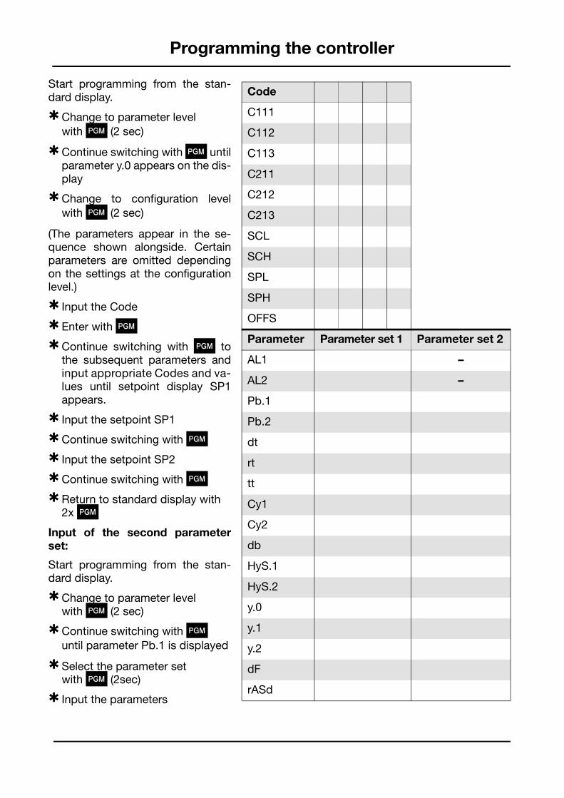
Start programming from the stan-dard display.
HChange to parameter level with P (2 sec)
HContinue switching with P untilparameter y.0 appears on the dis-play
HChange to configuration levelwith P (2 sec)
(The parameters appear in the se-quence shown alongside. Certainparameters are omitted dependingon the settings at the configurationlevel.)
H Input the Code
H Enter with P
HContinue switching with P tothe subsequent parameters andinput appropriate Codes and va-lues until setpoint display SP1appears.
H Input the setpoint SP1
HContinue switching with P
H Input the setpoint SP2
HContinue switching with P
HReturn to standard display with 2x P
Input of the second parameterset:
Start programming from the stan-dard display.
HChange to parameter levelwith P (2 sec)
HContinue switching with Puntil parameter Pb.1 is displayed
HSelect the parameter set with P (2sec)
H Input the parameters
Code
C111
C112
C113
C211
C212
C213
SCL
SCH
SPL
SPH
OFFS
Parameter Parameter set 1 Parameter set 2
AL1 –
AL2 –
Pb.1
Pb.2
dt
rt
tt
Cy1
Cy2
db
HyS.1
HyS.2
y.0
y.1
y.2
dF
rASd

TEMATEC Löbach GmbH
Postadresse: Hausadresse: Telefon (+49) 0 22 42-8703-0Postfach 1261 Löhestr. 37 Telefax (+49) 0 22 42-8703-20
http: // www.tematec.de53759 Hennef 53773 Hennef e-mail: [email protected]