type sa-1 generator differential relay - abb group · pdf file ·...
TRANSCRIPT
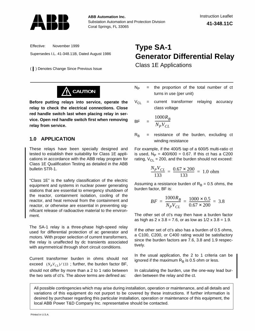
ABB Automation Inc.Substation Automation and Protection Division Coral Springs, FL 33065
Instruction Leaflet
All possible contingencies which may arise during installation, operation or maintenance, and all details andvariations of this equipment do not purport to be covered by these instructions. If further information isdesired by purchaser regarding this particular installation, operation or maintenance of this equipment, thelocal ABB Power T&D Company Inc. representative should be contacted.
Printed in U.S.A.
��� 41-348.11C
Effective: November 1999
Supersedes I.L. 41-348.11B, Dated August 1986
( ) Denotes Change Since Previous Issue
Type SA-1Generator Differential RelayClass 1E Applications
CAUTION!Before putting relays into service, operate therelay to check the electrical connections. Closered handle switch last when placing relay in ser-vice. Open red handle switch first when removingrelay from service.
1.0 APPLICATION
These relays have been specially designed andtested to establish their suitability for Class 1E appli-cations in accordance with the ABB relay program forClass 1E Qualification Testing as detailed in the ABBbulletin STR-1.
“Class 1E” is the safety classification of the electricequipment and systems in nuclear power generatingstations that are essential to emergency shutdown ofthe reactor, containment isolation, cooling of thereactor, and heat removal from the containment andreactor, or otherwise are essential in preventing sig-nificant release of radioactive material to the environ-ment.
The SA-1 relay is a three-phase high-speed relayused for differential protection of ac generator andmotors. With proper selection of current transformers,the relay is unaffected by dc transients associatedwith asymmetrical through short circuit conditions.
Current transformer burden in ohms should notexceed ; further, the burden factor BF,
should not differ by more than a 2 to 1 ratio betweenthe two sets of ct’s. The above terms are defined as:
NP = the proportion of the total number of ct
turns in use (per unit)
VCL = current transformer relaying accuracy
class voltage
BF =
RB = resistance of the burden, excluding ct
winding resistance
For example, if the 400/5 tap of a 600/5 multi-ratio ctis used, NP = 400/600 = 0.67. If this ct has a C200rating, VCL = 200, and the burden should not exceed:
Assuming a resistance burden of RB = 0.5 ohms, theburden factor, BF is:
The other set of ct’s may then have a burden factoras high as 2 x 3.8 = 7.6, or as low as 1/2 x 3.8 = 1.9.
If the other set of ct’s also has a burden of 0.5 ohms,a C100, C200, or C400 rating would be satisfactorysince the burden factors are 7.6, 3.8 and 1.9 respec-tively.
In the usual application, the 2 to 1 criteria can beignored if the maximum RB is 0.5 ohm or less.
In calculating the burden, use the one-way lead bur-den between the relay and the ct.
(NPVCL) 133⁄
1000RB
NPVCL-------------------
NPVCL
133----------------- 0.67 200×
133------------------------- 1.0 ohm= =
BF1000RB
NPVCL------------------- 1000 0.5×
0.67 200×------------------------- 3.8= = =

41-348.11C SA-1 Generator Differential Relay - Class 1E
2
2.0 CONSTRUCTION
The type SA-1 relay consists of:
• Restraint Circuit • Operating Circuit• Sensing Circuit • Amplifier Circuit• Trip Circuit • Indicating Circuit• Surge Protection Circuit • External Reactors
The principal parts of the relay and their location areshown in Figures 1 through 4 (page 5 thru page 9)and Figure 14 (page 16).
2.1 RESTRAINT CIRCUIT
The restraint circuit of each phase consists of a cen-ter-tapped transformer, a resistor, and a full-waverectifier bridge. The outputs of all the rectifiers areconnected in parallel. The parallel connection of rec-tifiers is a maximum voltage network. Hence, thevoltage applied to the filter circuit is proportional tothe phase current with the largest magnitude.
2.2 OPERATING CIRCUIT
The operating circuit consists of a transformer, aresistor, and a full wave rectifier bridge. The outputsof all the rectifiers are connected in parallel. This par-allel connection of rectifiers is a maximum voltagenetwork. Hence, the voltage applied to the filter cir-cuit is proportional to the differential current with thelargest magnitude.
2.3 SENSING CIRCUIT
The sensing circuit is connected to the output of therestraint filter circuit, the operating filter circuit andthe input to the amplifier circuit.
2.4 AMPLIFIER CIRCUIT
The amplifier circuit consists of a two-transistoramplifier which controls the operation of a relaxationoscillator.
The amplifier circuit is connected to the sensing cir-cuit such that it receives the difference in output ofthe restraint filter and the operating filter. Thus, thepolarity of the input voltage to the amplifier dependsupon the relative magnitude of the voltages appear-ing on the restraint and operating filters. When thevoltage output of the operating filter is greater thanthe output voltage of the restraint filter, a voltage of acertain polarity appears across the input of the ampli-fier. To trigger the amplifier requires that the outputvoltage of the operating filter be greater than the out-put voltage of the restraint filter.
2.5 TRIP CIRCUIT
The trip circuit consists of a thyristor which has ananode, cathode, and a gate. The anode of the thyris-tor is connected to the positive side of the dc supplyand the cathode of the thyristor is connected to thenegative side of the dc supply through the trip coil ofa breaker. The gate of the thyristor is connected tothe output of the amplifier circuit through a pulsetransformer.
With no gate current flowing, the thyristor acts as anopen circuit to the breaker trip coil. When a gate cur-rent is applied to the thyristor, the thyristor connectsthe breaker trip coil to the dc supply.
2.6 INDICATING CIRCUIT
The indicating circuit is triggered by a signal from theamplifier of the relay. Under normal or non-fault con-ditions, the indicating circuit is turned off. When afault is applied to the relay, the amplifier will conductto cause a signal to flow into the indicator circuit.When the indicator circuit is triggered, the lamp willturn on. This lamp will remain lit until the indicator cir-cuit is interrupted by resetting the micro-switch.
2.7 SURGE PROTECTION CIRCUIT
The surge protection circuit consists of two capaci-tors (C10 and C11) and a RC network which is con-nected across the anode and cathode of the trippingthyristor to prevent the SCR from firing by a surgevoltage on the dc supply.
2.8 EXTERNAL REACTORS
Three reactors are mounted on a metal plate with aseparate terminal strip. The reactors are of the satu-rable type.
3.0 OPERATION
The type SA-1 relay is connected to the protectedapparatus as shown in Figure 5 (page 10). On exter-nal faults, current flows through the primary windingof the restraint transformers to induce a voltage onthe restraint side of the sensing circuit. If the two setsof main current transformers have different perfor-mances, some current will flow out of the mid-tap ofthe restraint transformers to the operating transform-ers. This will produce a voltage on the operating sideof the sensing circuit. With the relay correctly applied,sufficient restraint voltage will exist to prevent theoperating voltage from triggering the amplifier.

SA-1 Generator Differential Relay - Class 1E 41-348.11C
3
The percentage slope characteristic of the relay lim-its the operating voltage on heavy external faultswhere the performance of the two sets of currenttransformers may be quite different.
On internal faults, the operating coil current is the dif-ference of the current flowing in each of the windingsof the restraint transformer and sufficient operatingvoltage is available to overcome the restraint voltage.
4.0 CHARACTERISTICS
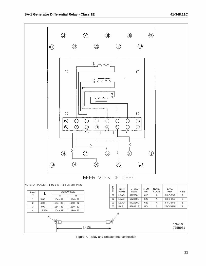
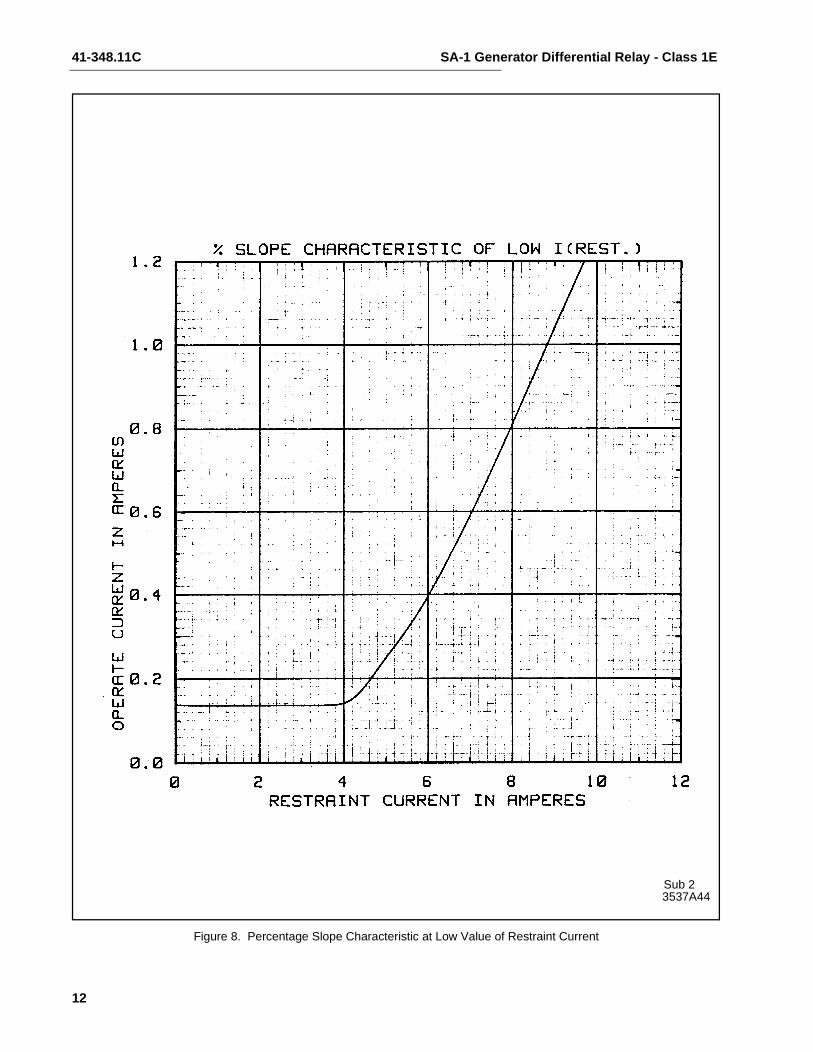
The percentage slope curves are shown in Figures 8and 9 (page 12 and page 13). It will be observed thatthe relay operates at 5% unbalance at 5 amperesrestraint (Figure 8, page 12) to provide high sensitiv-ity for internal faults up to full load conditions. At 60amperes restraint, the operating current required totrip the relay is 30 amperes or 50% unbalance (Fig-ure 9, page 13). Thus, when 60 amperes throughfault current is flowing, the output of the main currenttransformers may vary considerably without causingincorrect operation.
The minimum pickup of the relay is 0.14 amperes.
The time curve of the relay is shown in Figure 10(page 14).
The frequency response characteristic of the TypeSA-1 relay is shown in Figure 11 (page 15).
5.0 ENERGY REQUIREMENTS
5.1 EACH RESTRAINT CIRCUIT
Burden at 5 amperes is 0.25 VAContinuous rating 20 amperes1 second rating 300 amperes
5.2 OPERATING CIRCUIT
The burden imposed by the operating circuit on eachcurrent transformer is variable because of the satu-rating transformer. At 0.5 amperes, it is 1.48 ohms,and at 60 amperes, it is 0.47 ohms.
Note that the neutral reactors are in series with theoperating coil circuit. They also have a saturatingcharacteristic, with a maximum impedance of roughly80 ohms.
Continuous rating 10 amperes1 second rating 200 amperes
5.3 AMPLIFIER
The dc burden on the station battery is:
6.0 SETTINGS
There are no taps on either transformer and, conse-quently, there are no settings to be made. The48/125 Vdc relays are normally shipped for 125 volts.For 48 Vdc applications use the mid tap on the resis-tor mounted at the top of the relay. The red dot on theresistor is the common point – DO NOT REMOVE.
7.0 INSTALLATION
The relays should be mounted on switchboard pan-els or their equivalent in a location free from mois-ture. Mount the relay vertically by means of the fourmounting holes on the flange for semi-flush mount-ing.
Either a mounting stud or the mounting screws maybe utilized for grounding the relay. The electrical con-nections may be made directly to the terminals bymeans of screws.
The external reactor assembly should be mountedand wired per “Interwiring Connection Drawing”, Fig-ure 7 (page 11).
For detailed FT case information, refer to InstructionLeaflet 41-076.
8.0 ADJUSTMENTS AND MAINTENANCE
The proper adjustments to insure correct operation ofthis relay have been made at the factory and shouldnot be disturbed after receipt by the customer.
8.1 ROUTINE TEST
The following check is recommended to insure thatthe relay is in proper working order. All checks canbest be performed by connecting the relay per thetest circuit of Figure 12 (page 15). Due to high imped-ance of the external reactor, prior to saturation, thetest circuit of Figure 12 should be used to test therelay only. The reactors can be checked by applying
Volts Milliamperes Watts
125 dc48 dc
5560
6.92.9

41-348.11C SA-1 Generator Differential Relay - Class 1E
4
0.2 amperes 60 hertz and reading the voltage dropacross the reactor with a high impedance true rmsreading voltmeter. The voltage drop will be between20 and 26 V (true rms). For 0.4 amperes input, thereading should be between 24 and 31 volts (truerms).
1. Minimum Trip Current with IR set at zero
amperes, apply 0.14 ± 5% amperes operatingcurrent to each operating circuit of the relay. Therelay should operate and the indicator lampshould light.
2. Differential Characteristic
a) Apply IR of 5 amperes and adjust the operat-ing current until the relay operates. The relayshould operate and the indicator lamp shouldlight with an operating current of 0.25± 0.012 amperes. Repeat for each phase ofthe relay.
b) Apply IR of 60 amperes and adjust the oper-ating current until the relay operates. Therelay should operate and the indicator lampshould light with an operating current of 30± 3 amperes. Repeat for each phase of therelay.
8.2 MAINTENANCE
All relays should be checked once a year to detectthe electronic component failures which occur on arandom basis. The tantalum capacitors C1, C2, C3,C4 and C13 may have a common mode failure char-acteristic and should be checked visually for symp-toms of electrolyte leakage every year and replacedif necessary.
9.0 CALIBRATION
Use the following procedure for calibrating the relay ifthe relay adjustments have been disturbed. This pro-cedure should not be used until it is apparent therelay is NOT in proper working order.
1. Minimum Trip Current – Connect the relay pertest circuit of Figure 12 (page 15). With switch Kopen, adjust the operating resistor in the rear ofthe relay until the relay operates with I0 equal to0.14 amperes. Do not make adjustments to theresistor unless the dc is disconnected.
The indicator lamp should light when the relay operates.
Repeat for each phase of the relay.
2. Percentage Slope Characteristic (Low Cur-rent) – Set IR equal to 5 amperes and adjust therestraint resistor in the rear of the relay until therelay operates with I0 = 0.25 ± 0.012 amperes.Do not adjust resistor with dc applied to relay.
The indicator lamp should light when the relay operates.
Repeat for each phase of the relay.
Percentage Slope Characteristic (High Cur-rent) – Set IR equal to 60 amperes for the operat-ing current of 30 amperes. Replace the resistor R17 if necessary. The value of R17 can be between 0 and 100 ohms. Repeat for the other two phases, if necessary, replacing R18 and R19 respectively.
3. Electrical Checkpoints – See Table 1 (pagepage 6)
10.0 ELECTRICAL CHECKPOINTS
Connect relay per test circuit of Figure 12 (page 15).All voltage readings should be made with a highresistance voltmeter. Refer to Figure 4 (page 9) forthe location of checkpoints. Voltage readings areapproximate. The voltage readings “Input to Ampli-fier” should NOT be taken with relay in service.
11.0 RENEWAL PARTS
Repair work can be done most satisfactorily at thefactory. However, interchangeable parts can be fur-nished to customers who are equipped for doingrepair work. When ordering parts, always give thenameplate data.

SA-1 Generator Differential Relay - Class 1E 41-348.11C
5
Fig
ure
1.T
ype
SA
-1 G
ener
ator
Diff
eren
tial R
elay
with
out C
ase
(Fro
nt V
iew
)F
igur
e 2.
Typ
e S
A-1
Gen
erat
or D
iffer
entia
l Rel
ay w
ithou
t Cas
e (R
ear
Vie
w)
LBLMLT
UB
UM
UT
Ter
min
alN
umbe
rs

41-348.11C SA-1 Generator Differential Relay - Class 1E
6
Table 1: (Values in Parenthesis Represent Desensitized SA-1)
CIRCUITPRIMARYCURRENT PHASE
CHECKPOINTS (TYPICAL VALUE)
TERMINAL VALUE FUNCTION
Operating0.14A 1
23
2 - 73 - 64 - 5
2.5 ac2.5 ac2.5 ac
Input to operate rectifierInput to operate rectifierInput to operate rectifier
Sensing(Operating)
0.14AAny
Phase
+ to -23 - 2624 - 2624 - 88 - 25
25 - 26
2.1 dc1.85 dc0.55 dc0.65 dc0.65 dc
Ref: a = b + c + dOutput to rectifiera. Output to operating sensing circuitb. Input to amplifierc.d. Output to restraint sensing circuit
30.0AAny
Phase+ to -
24 - 26 51.0 dc
Restraint5.0A 1
23
18 - 1317 - 1415 - 16
6.0 ac6.0 ac6.0 ac
Input to restraint rectifierInput to restraint rectifierInput to restraint rectifier
Sensing(Restraint)
5.0A AnyPhase
+ to -25 - 2625 - 88 - 24
24 - 26
2.1 dc1.2 dc0.6 dc0.3 dc
Ref: a = b + c + da. Output to restraint sensing circuitb. c. Input to amplifierd. Output to operating sensing circuit
60.0AAny
Phase+ to -
25 - 26 42.0 dc
Amplifier
0 + to -27 - 812 - 810 - 8
0.7 dc24.0 dc24.0 dc
MinimumTrip
Current+5%
AnyPhase
+ to -27 - 812 - 821 - 8
0.5 dc24.0 dc10.0 dc
NOTE: Terminal numbers refer to the printed circuit board (See Figure 4)

SA-1 Generator Differential Relay - Class 1E 41-348.11C
7
Table 2: Electrical Parts List
CIRCUIT SYMBOL REFERENCE STYLE
Resistors UT, UM, UBResistors LT, LM, LBResistors R14Zener Z2SCRReactor L1
60 Ohms, 25W265 Ohms, 25W1.8K, 40WIN2986B
18756761725542187A321H06629A798H03184A614H051478B98G01
SA Module Style Number 408C673G01 Sub 45
Resistor R1Resistor R2Resistor R3, R4, R5Resistor R6Resistor R7Resistor R8Resistor R9Resistor R10Resistor R11Resistor R12Resistor R13Resistor R17, R18, R19
Capacitor C1, C2, C3, C13Capacitor C4Capacitor C5Capacitor C6Capacitor C7Capacitor C8, C9
Diode D1 to D24Diode D25, D26
Zener Z1SCRTransistor T1, T2Transistor T3Transformer TR-1
270 Ohms, 1W2K, 5%15K, 5%2.7K, 5%68K, 5%27K, 5%2.2K, 5%100 Ohms, 10%220 Ohms, 5%680 Ohms, 5%47K, 5%33 Ohms, 5%
25 MFD, 125V22 MFD, 35V0.5 MFD, 200V2.2 MFD, 35V2.0 MFD, 200V0.47 MFD, 50V
IN4821IN645A
IN752AK1149-132N34172N2647
629A531H18184A763H34184A763H55184A763H37184A763H71184A763H61184A763H35187A643H03184A763H11184A763H23184A763H67187A290H13
184A637H01184A661H16187A624H11837A241H16187A624H05762A680H04
188A342H16837A692H03
186A797H12184A640H13848A851H02629A435H01629A372H02
SPK Module Style Number 1584C01G01
Resistor R15Capacitor C10, C11Capacitor C12
470 Ohms, 1W0.01 MFD, 1.5KV2.0 MFD, 200V
187A643H193536A32H023509A33H01

41-348.11C SA-1 Generator Differential Relay - Class 1E
8
Figure 3. Internal Schematic of Type SA-1 Relay in Type FT-32 Case 48/125 Vdc
*Sub 93520A40

SA-1 Generator Differential Relay - Class 1E 41-348.11C
9
Figure 4. Component Location on Printed Circuit Board Type SA-1 Relay 48/125 Vdc
3525A93Sub 3

41-348.11C SA-1 Generator Differential Relay - Class 1E
10
Figure 5. External Schematic of Type SA-1 Relay for Generator Protection
Figure 6. Reactor Outline
775B965Sub 4
775B982Sub 1
SA-1 Generator Differential Relay - Class 1E 41-348.11C
11
Figure 7. Relay and Reactor Interconnection
775B981* Sub 5
NOTE: A - PLACE IT. 1 TO 3 IN IT. 5 FOR SHIPPING
LeadIT. L SCREW SIZE
A B
1 3.00 .164 - 32 .164 - 32
2 4.00 .164 - 32 .190 - 32
3 3.00 .164 - 32 .190 - 32
4 13.438 .164 - 32 .190 - 32
ITE
M
PARTNAME
STYLEDWG.
ITEMGR.
NOTECODE
ENG.REF. REQ
01 LEAD 57Z0301 616 A 63-D-653 2
02 LEAD 57Z0401 622 A 63-D-655 3
03 LEAD 57Z0301 622 A 63-D-655 1
05 BAG 836A618 H04 B 27-D-5478 1
AB
L±.156
41-348.11C SA-1 Generator Differential Relay - Class 1E
12
Figure 8. Percentage Slope Characteristic at Low Value of Restraint Current
3537A44Sub 2
SA-1 Generator Differential Relay - Class 1E 41-348.11C
13
Figure 9. Percentage Slope Characteristic at High Value of Restraint Current
878A742Sub 3

41-348.11C SA-1 Generator Differential Relay - Class 1E
14
Figure 10. Typical Operation Time Characteristic
471106

SA-1 Generator Differential Relay - Class 1E 41-348.11C
15
Figure 11. Typical Frequency Response Curve
Figure 12. Test Diagram for Type SA-1 Relay
3537A45Sub 2
184A864Sub 6

Printed in U.S.A.
ABB Automation Inc.4300 Coral Ridge Drive
Coral Springs Florida 33065
TEL: 954-752-6700
FAX: 954-345-5329
���
41-348.11C SA-1 Generator Differential Relay - Class 1E
Figure 14. Relay Type SA-1 Class 1E Component Location of the SPK Module
Illustration
C10
C11
C12R15
2
1 345
SPK 1584C01G01
C11 & C10 .01 uf 3536A32H02C12 2.0 uf 3509A33H01R15 470 Ohm 187A643H19Int. Schematic 3520A40
COMPONENT LOCATION48/125 V
Figure 13. Outline and Drilling Plan for Type SA-1 Relay in Type FT-32 Case for Class 1E Application
3519A69* Sub 4