ucl université catholique de louvain reddot/iag/documents/wp_06... · ucl université catholique...
TRANSCRIPT

UCLInstitut d’administration et de gestionUniversité catholique de Louvain
RESEARCH REPORT
Academic Year 2004-2005

S-Tropos: An Iterative SPEM-Centric Software Project Management Process
Yves Wautelet, Manuel Kolp, Youssef Achbany
IAG – Institut d’Administration et de Gestion, ISYS – Unité de Systèmes d’Information,
Université Catholique de Louvain, 1 Place des Doyens, Belgium Email: {wautelet, kolp, [email protected]}
1 Introduction......................................................................................................... 3 2 S-Tropos: an Agent-Oriented Software Development Methodology.................. 4
2.1 The Software Process Engineering Metamodel (SPEM) ............................. 5 2.2 The Process .................................................................................................. 6 2.3 S-Tropos’ Disciplines Specification Using SPEM Notation........................ 9
2.3.1. Early Requirements ................................................................................ 9 2.3.1.1. Package ........................................................................................... 9 2.3.1.2. Work Definitions............................................................................. 9 2.3.1.3. Workflow ...................................................................................... 10 2.3.1.3. Work Products............................................................................... 12
2.3.2. Late Requirements ............................................................................... 13 2.3.2.1. Package ......................................................................................... 13 2.3.2.2. Work Definitions........................................................................... 14 2.3.2.3. Workflow ...................................................................................... 14 2.3.2.4. Work Products............................................................................... 16
2.3.3. Architectural Design ............................................................................ 17 2.3.3.1. Package ......................................................................................... 17 2.3.3.2. Work Definitions........................................................................... 17 2.3.3.3. Workflow ...................................................................................... 18 2.3.3.4. Work Products............................................................................... 20
2.3.4. Detailed Design.................................................................................... 22 2.3.4.1. Package ......................................................................................... 22 2.3.4.2. Work Definitions........................................................................... 22 2.3.4.3. Workflow ...................................................................................... 23 2.3.4.4. Work Products............................................................................... 25
2.3.5. Development ........................................................................................ 27 2.3.5.1. Package ......................................................................................... 27 2.3.5.2. Work Definitions........................................................................... 28 2.3.6.3. Workflow ...................................................................................... 28 2.3.5.4. Work Products............................................................................... 30
2.3.6. Validation............................................................................................. 31
1

2.3.6.1. Package ......................................................................................... 31 2.3.6.2. Work Definitions........................................................................... 32 2.3.6.3. Workflow ...................................................................................... 32 2.3.6.4. Work Products............................................................................... 34
2.3.7. Deployment .......................................................................................... 35 2.3.7.1. Package ......................................................................................... 35 2.3.7.2. Work Definitions........................................................................... 35 2.3.7.3. Workflow ...................................................................................... 36 2.3.7.4. Work Products............................................................................... 38
2.3.8. Risk and Project Management.............................................................. 39 2.3.8.1. Package ......................................................................................... 39 2.3.8.2. Work Definitions........................................................................... 40 2.3.8.3. Workflow ...................................................................................... 40 2.3.8.4. Work Products............................................................................... 42
2.4 Work Product Dependency ........................................................................ 42 2.5 S-Tropos Roles........................................................................................... 43
3 Conclusion and Future Work ............................................................................ 44 References.............................................................................................................. 45
2

S-Tropos: An Iterative SPEM-Centric Software Project Management Process
Yves Wautelet, Manuel Kolp, Youssef Achbany
IAG – Institut d’Administration et de Gestion, ISYS – Unité de Systèmes d’Information,
Université Catholique de Louvain, 1 Place des Doyens, Belgium Email: {wautelet, kolp, [email protected]}
Abstract. Today’s enterprise information systems have to match with their op-erational and organizational environment. Unfortunately, software project man-agement methodologies are traditionally inspired by programming concepts and not by organizational and enterprise ones. In order to reduce as much this dis-tance, Multi-Agent Systems emerged over the last 10 years. They better meet the increasing complexity and flexibility required to develop software applica-tions built in open-networked environments and deeply embedded into human activities; that is why they are so successful. Thanks to the benefits of a Spiral System Development Life Cycle (SDLC), software engineering methodologies such as the Unified Process are widely in use today. Those methodologies are nevertheless all applied to object-oriented modeling and today’s agent-oriented software development methodologies only use waterfall SDLCs. They are con-sequently not suited for the development of huge and complex user-interactive applications. This paper proposes a generic process specification using SPEM notation (and UML Profile for SPEM) of an original agent-oriented software engineering methodology using a spiral SDLC. This methodology is called S-Tropos1.
1 Introduction
Computing science and techniques are deeply linked to human activities. Software development methodologies are however traditionally inspired by programming con-cepts and not by organizational and enterprise ones. This leads to ontological and semantic gaps between the systems and their environments. The use of Multi-Agent Systems (MAS) [Wooldridge95] reduces these gaps by offering modeling tools based on organizational concepts (actors, agents, goals, objectives, responsibilities, social dependencies, etc.) as fundamentals to conceive software systems through all the development process. Moreover, software development is becoming increasingly complex. Stakeholders’ expectations are growing higher while the time to market has to be as low as possible. In order to be competitive in such markets, analysts, project leaders, software developers need adequate methodologies to model the organization, 1 S-Tropos stands for Spiral Tropos.
3

capture requirements and build efficient and flexible software systems. Those meth-odologies have to cover the whole project life cycle while reducing risk as much as possible. For user-interactive software applications the objective will be better achieved using Spiral Development [Boehm88]. Indeed the later is able to deal with an environment facing difficulties to capture rapidly evolving requirements in an efficient way. Most agent-oriented development methodologies use a traditional wa-terfall SDLC [Royce70].
The aim of this paper is to describe and formalize a generic process for an original
spiral software development methodology for developing MAS using the Software Process Engineering Metamodel (SPEM) notation [SPEM]. The goal of this software process is to extend the Tropos [Castro03] waterfall SDLC methodology to include the advantages of spiral development such as efficient software project management, continuous organizational modeling and requirements acquisition, early implementa-tion, continuous testing and modularity to agent-oriented software (see [Wautelet05]). The SPEM notation is an Object Management Group (OMG) specification of an UML metamodel (and UML profile) to represent a family of software development processes and their components. This metamodel is becoming more popular and has already been used to specify other Agent-Oriented software development methodolo-gies such as Passi [Burrafato02, Cossentino03], Adelfe [Bernon02, Gleizes03] or Gaia [Wooldridge00, Garro04]. Consequently it has been chosen to formalize the generic S-Tropos process.
The paper is structured as follows. A brief overview of the SPEM and its relevant
notions is firstly made. After that, the S-Tropos generic process is formalized using the SPEM notation in both its horizontal (the phases and iterations) and vertical (the disciplines) dimensions. Finally, last section concludes the paper and points to further work.
2 S-Tropos: an Agent-Oriented Software Development Methodology
Tropos [Castro02] is a MAS software development methodology founded on in-tentional and social concepts, inspired by early requirements analysis and using a waterfall SDLC. The four different stages of a MAS development using Tropos are Early Requirements, Late Requirements, Architectural Design and Detailed Design. Nevertheless, Tropos and the other Agent-Oriented methodologies do not yet cover all the aspects of the software engineering lifecycle depicted in the Spiral Model as some object-oriented development methodologies do (see for example the Unified Process [Jacobson99, Jacobson00, Kruchten03, RUP]). Obviously, the advantages of spiral development, such as efficient software project management, continuous organ-izational modeling and requirements acquisition, early implementation, continuous testing and modularity should be applied in the development of Agent-Oriented soft-ware. That’s why we present in this section a formalization of an original spiral soft-
4

ware development process for agent-oriented software development extending Tropos to allow iterative development. This methodology is called S-Tropos. A complete generic specification using the SPEM notation of this software development process is presented in this section.
2.1 The Software Process Engineering Metamodel (SPEM)
The SPEM is an OMG specification of an UML metamodel (and UML profile) to represent a family of software development processes and their components [SPEM]. It constitutes a sort of “ontology” of software development processes. SPEM provides the minimum set of process modeling elements necessary to describe any software development process without adding specific models or constraints for any specific area or discipline, such as project management or analysis.
A full description of the SPEM including each concept described below and their
hierarchy can be found in [SPEM]. Some relevant SPEM concepts used in this paper are (Figure 1 depicts, when existing, their related icons):
• The WorkDefinition. It constitutes a kind of operation that describes the work performed in the process;
• The Phase. It constitutes a specialization of the WorkDefinition such that its precondition defines the phase entry criteria and its goal (often called a “mile-stone”) defines the phase exit criteria;
• The Iteration. It constitutes a composite WorkDefinition with a minor mile-stone;
• The WorkProduct. It constitutes an artifact of a process; any tangible piece of information that is produced consumed or modified by a process;
• The ProcessRole. It defines responsibilities over specific WorkProducts; • The Activity. It constitutes a piece of work performed by a single ProcessRole; • The Discipline. It partitions the Activites within a process according to a com-
mon “theme”; • The ModelElement. It constitutes an element describing one aspect of a soft-
ware engineering process; • The Guidance. It constitutes an element aimed to provide more detailed in-
formation about the associated ModelElement; • The Document. It constitutes a stereotype (“a special kind”) of WorkProduct; • The UMLModel2. It constitutes a stereotype (“a special kind”) of WorkPro-
duct; • The MASModelElement. It constitutes a stereotype (“a special kind”) of
WorkProduct (see [Cossentino03]).
2 Note that this stereotype will be used in this paper to represent i* [Yu95], AUML [AUML],
etc. models which are not strictly speaking models referring to the Unified Modeling Lan-guage [UML].
5

Workproduct
ActivityProcessRole
Document
Guidance
WorkDefinition Phase
UMLModel MASMeta-ModelElement
Figure 1. Some SPEM Icons
2.2 The Process
Due to the use of a Spiral SDLC, an “S-Tropos development” is made of disci-plines repeated iteratively while the effort spend on each discipline is variable from one iteration to another. The two Requirements and the two Design disciplines are inspired by Tropos in its waterfall version. S-Tropos includes core activities i.e. Early Requirements, Late Requirements, Architectural Design, Detailed Design, Develop-ment, Validation and Deployment but also a support activity (to support the project development) called Risk and Project Management. Indeed, there is little need for support activities in a process using a waterfall SDLC since the core disciplines are achieved ones for all and the one after the other. Nevertheless when dealing with a process using a Spiral SDLC, a support discipline for managing the whole process is from primary importance. Figure 2 presents S-Tropos process’ disciplines package diagram.
<< Discipline >>Early Requirements
S-Tropos
<< Discipline >>Late Requirements
<< Discipline >>Architectural Design
<< Discipline >>Detailed Design
<< Discipline >>Development
<< Discipline >>Validation
<< Discipline >>Deployment
<< Discipline >>Risk and Project Management
Figure 2. The S-Tropos Process’ Disciplines Package Diagram
6

As mentioned in the previous paragraph, using a spiral SDLC implies repeating the
disciplines iteratively. Each iteration belongs to one of the four S-Tropos’ phases (i.e. setting, prototyping, building and producing). These four phases are achieved sequen-tially and have different goals (achieved through the WorkDefinitions) and evaluated at milestones at the end of each phase. WorkDefinitions checking is performed at the milestones through the use of knowledge and achievement oriented metrics3. A com-plete specification of the milestones featuring their metrics will be realized soon. The phases and their WorkDefinitions are presented in Figure 3 while Figure 4 offers a two dimensional view of the S-Tropos process: it shows the eight disciplines and the four different phases they belong to. Finally, another vision of the S-Tropos process showing the spiral perspective is presented in Figure 5.
First Stakeholders Analysis
Setting
Prototyping
Building
Producing
First Environment Scope Definition
Project Risk AssessmentConsistent System Architecture Produced
Most Requirements Identified and Defined
Highly Risked Features Understood and Eliminated
Remaining Requirements Identified
Detail System Design
Make Sure the System Meets Users Expectations
Make Sure the System Fits in the Organization
Finalize Production
Training the Users
System Documentation and Manuals Written
<< include >>
<< include >>
<< include >>
<< include >>
<< include >>
<< include >>
<< include >>
<< include >>
<< include >>
<< include >>
<< include >>
<< include >>
<< include >>
Figure 3. The S-Tropos phases and their WorkDefinitions
3 A metric is some measurement we can make of a product or process in the overall develop-
ment process.
7

Early
Requirements
Late
Requirements
Architectural
Design
Detailed
Design
Development
Validation
Early
Requirements
Late
Requirements
Architectural
Design
Detailed
Design
Development
Early
Requirements
Late
Requirements
Architectural
Design
Detailed
Design
Development
Early
Requirements
Late
Requirements
Architectural
Design
Detailed
Design
Development
Early
Requirements
Late
Requirements
Architectural
Design
Detailed
Design
Development
Early
Requirements
Late
Requirements
Architectural
Design
Detailed
Design
Development
Early
Requirements
Late
Requirements
Architectural
Design
Detailed
Design
Development
SETTING PROTOTYPING BUILDING PRODUCING
D
I
S
C
I
P
L
I
N
E
S
Milestone Milestone Milestone Milestone
Validation Validation Validation Validation Validation
Validation TestDeployment Deployment Deployment Deployment Deployment Deployment Deployment
TestRisk and Project
Management
Risk and Project
Management
Risk and Project
Management
Risk and Project
Management
Risk and Project
Management
Risk and Project
Management
Risk and Project
Management
Validation
Figure 4. S-Tropos: an Iterative Perspective
InitialInitialProjectProject
PlanningPlanning
IterationIterationPlanningPlanning
EarlyEarlyRequirementsRequirements
ArchitecturalArchitecturalDesignDesign
DetailedDetailedDesignDesign
DevelopmentDevelopment
ValidationValidation
IterationIterationEvaluationEvaluation
SoftwareSoftwareProjectProject
ManagementManagement
LateLateRequirementsRequirements
AnchorAnchorPointPoint
MilestonesMilestones
For each iterationFor each iterationan executablean executable
releasereleaseis producedis produced
RiskRiskManagementManagement
Deployment
Figure 5. S-Tropos: an Spiral Perspective
8

2.3 S-Tropos’ Disciplines Specification Using SPEM Notation
In this section the S-Tropos disciplines will be presented and studied in detail fol-lowing the UML Profile for SPEM. After briefly describing their goal, each discipline is drawn as a package (made of Roles, Activities, WorkProducts and Guidances speci-fied in detail in the section). A WorkDefinitions workflow is also presented and speci-fied. WorkDefinitions are then split into a detailed workflow in which each activity is presented with respect to its sequence. Finally, the disciplines WorkProducts are also specified and their relationships are drawn using a UML Class Diagram.
2.3.1. Early Requirements Early Requirements Analysis is concerned with the understanding of a problem by
studying an existing organizational setting. The emphasis is put on understanding the motivation and rationale that underlie system requirements. During this phase, re-quirements engineers model the target domain in terms of (social) actors and inten-tions. This analysis addresses directly the object-oriented deficiencies in modeling the problem domain. Each goal intention is analyzed from the point of view of the actors resulting in a set of social dependencies between actors.
2.3.1.1. Package As shown in Figure 6, the Early Requirements discipline involves two Process-
Roles, four WorkProducts (two UML Models and two text documents) and a Guid-ance related to the two UML models.
Early Requirements
Strategic Dependency Model
The i* Modeling Framework
Requirements Engineer Stakeholder
Identify Stakeholders ()
Determine Stakehoders Intentions ()
Validate Identified Intentions ()
Structure i* Model ()
Perform Means-Ends Analysis with Identified Goals/Softgoals ()
Stakeholder List Stakeholder Intentions ListStrategic Rationale Model
Figure 6. Early Requirements as a SPEM discipline
2.3.1.2. Work Definitions In this section the WorkDefinitions performed during the Early Requirements dis-
cipline are presented. Figure 7 shows their workflow, for further refinements see Figure 8 and Table 1.
9

Stakeholders Analysis
Strategic Rationale ModelStakeholders List Stakeholders Intentions List
Strategic Analysis
Strategic Dependency Model
[New Iteration]
Figure 7. Early Requirements Work Definitions
2.3.1.3. Workflow In this section a complete specification of the activities performed during the Early
Requirements discipline is developed in Table 1, the workflow of these activities is presented in Figure 8.
Identify Stakeholders
Stakeholders List
Strategic Dependency Model
: Requirements Engineer : Stakeholder
Determine Stakehoders Intentions
[More Stakehoders]
[All Stakehoders Identified]
Stakeholders Intentions List Validate Identified Intentions
[Stakehoder not OK]
[Stakehoder OK]
[More Stakeholders]
Structure i* Model
[All Intentions Validated]
Perform Means-EndsAnalysis with Identified Goals/Softgoals
Strategic Rationale Model
Strategic Analysis
Stakeholders Analysis
Figure 8. Early Requirements Workflow
10

N° Activity name Goal Process Role Pre Parent WorkDefinition
Output WorkProducts
1 Identify Stakeholders
The aim of this activity is to identify the stakeholders who will be represented as (social) actors
Requirements Engineer Stakeholders
Analysis A Stakeholders List
2 Determine
Stakeholders’ Intentions
The aim of this activity is to represent stakeholders’ intentions as goals/softgoals
Requirements Engineer Activity 1 Stakeholders
Analysis A Stakeholders Intentions List
3 Validate Identified Intentions
The identified stakeholders and their strategic dependencies are represented in a Strategic Dependency Model
Stakeholder Activity 2 Stakeholders Analysis
4 Structure i* Model The identified stakeholders and their strategic dependencies are represented in a Strategic Dependency Model
Requirements Engineer Activity 3 Strategic Analysis A Strategic
Dependency Model
5
Perform Means-Ends Analysis for
Identified Goals/Softgoals
Based on the goals and softgoals identified in the Strategic Dependency Model, Strategic Rationale Models are drawn
Requirements Engineer Activity 4 Strategic Analysis A Strategic Rationale
Model
Table 1. Early Requirements activities description
11

2.3.1.3. Work Products In this section a complete specification of the WorkProducts used as input or pro-
duced as output during the Early Requirements discipline is developed in Table 2, the relationships between these activities are presented in Figure 9.
WorkProduct
Name Type Description
Early Requirements Model WorkProduct
The Early Requirements Model is a model made of Text Documents, UML Models, etc. as structured in Figure 9
Stakeholders List Text Document
The Stakeholders List describes each Stakeholder identified
Stakeholders Intentions List
Text Document
The Stakeholders Intention List describes each Stakeholder and lists their identified intentions
Strategic Dependency Model UML Model
The Strategic Dependency Model (SD) describes the network of social relation-ships among actors
Strategic Rationale Model UML Model
The Strategic Rationale Model (SR) describes and supports the reasoning through which each actor goes with respect to its relationships with other actors
The i* Modeling Framework Guidance
The i* Modeling framework4 is an ontology founded on the notions of actor, goal and social dependency that includes two models formalized with the intentional concepts from the BDI model5
Table 2. Early Requirements Work Products description
4 i* stands for “distributed intentionality”. 5 BDI stands for Beliefs-Desires-Intentions (see [Weiss99]). Beliefs are the agent local knowl-
edge base, Desires are what the agent is trying to achieve and Intentions constitute its cur-rently adopted plans.
12

Early RequirementsModel
Stakeholders Intentions List
The i* Modeling Framework
Strategic Dependency Model Strategic Rationale Model
Stakeholders List
Figure 9. Early Requirements Work Products relationships
2.3.2. Late Requirements Late Requirements Analysis extends the models created in the previous step with
the target system in its environment. The system ‘to-be’ is modeled as one or more actors. Its interdependencies with other actors contribute to the accomplishment of stakeholder goals. Therefore, these dependencies define the target system's functional and non-functional requirements. The same process (i.e.: SD and SR analysis), is operated again but with the focus on the intended software system.
2.3.2.1. Package As shown in Figure 10, the Late Requirements discipline involves one Process-
Role, four WorkProducts (two UML Models and two text documents) and a Guid-ance related to the two UML models.
Late Requirements
Strategic Dependency Model
The i* Modeling Framework
Strategic Rationale Model
System Analyst
Identify System’s Environment ()
Determine System’s Environment Intentions ()
Structure Strategic Dependency Model ()
Perform Means-Ends Analysis with Identified Goals/Softgoals ()
Actors List Systems Environment Intentions List
Figure 10. Late Requirements as a SPEM discipline
13

2.3.2.2. Work Definitions In this section the WorkDefinitions performed during the Late Requirements disci-
pline are presented. Figure 11 shows their workflow, for further refinements see Fig-ure 12 and Table 3.
System Environment Analysis
Strategic Rationale ModelActors List System Environment Intentions List
Strategic Analysis
Strategic Dependency Model
[New Iteration]
Figure 11. Late Requirements Work Definitions
2.3.2.3. Workflow In this section a complete specification of the activities performed during the Late
Requirements discipline is developed in Table 3, the workflow of these activities is presented in Figure 12.
Identify System’s Environment
Actors List
: System Analyst
Determine System’s Environment Intentions
[More Actors]
[System’s Environment Identified]
Systems Environment Intentions List
Strategic Dependency Model
Structure Strategic Dependency Model
Perform Means-EndsAnalysis with Identified Goals/Softgoals
Strategic Rationale Model
System Environment Analysis
Strategic Analysis
Figure 12. Late Requirements Workflow
14
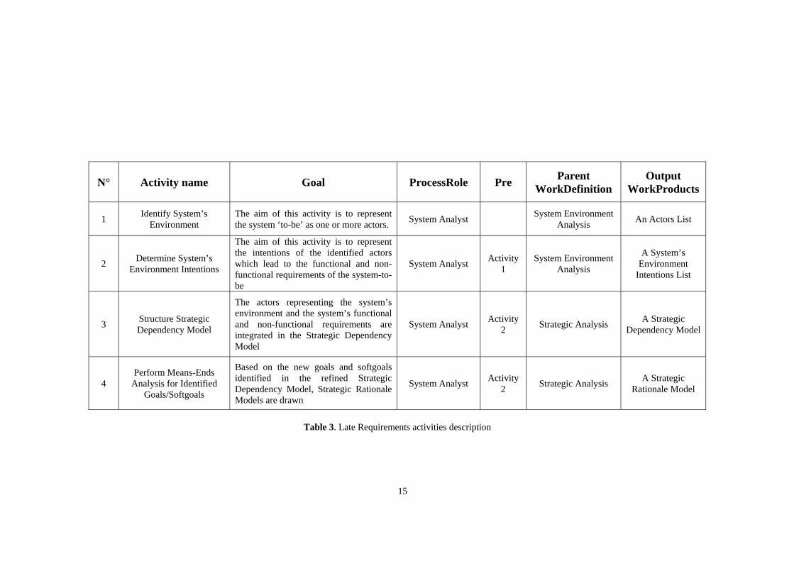
N° Activity name Goal ProcessRole Pre Parent WorkDefinition
Output WorkProducts
1 Identify System’s Environment
The aim of this activity is to represent the system ‘to-be’ as one or more actors. System Analyst System Environment
Analysis An Actors List
2 Determine System’s Environment Intentions
The aim of this activity is to represent the intentions of the identified actors which lead to the functional and non-functional requirements of the system-to-be
System Analyst Activity 1
System Environment Analysis
A System’s Environment
Intentions List
3 Structure Strategic Dependency Model
The actors representing the system’s environment and the system’s functional and non-functional requirements are integrated in the Strategic Dependency Model
System Analyst Activity 2 Strategic Analysis A Strategic
Dependency Model
4 Perform Means-Ends
Analysis for Identified Goals/Softgoals
Based on the new goals and softgoals identified in the refined Strategic Dependency Model, Strategic Rationale Models are drawn
System Analyst Activity 2 Strategic Analysis A Strategic
Rationale Model
Table 3. Late Requirements activities description
15

2.3.2.4. Work Products In this section a complete specification of the WorkProducts used as input or pro-
duced as output during the Late Requirements discipline is developed in Table 4, the relationships between these activities are presented in Figure 13.
WorkProduct
name Type Description
Late Requirements
Model WorkProduct
The Late Requirements Model is a model made of Text Documents, UML Models, etc. as structured in Figure 13
Actors List Text Document
The Actors List describes each the system ‘to-be’ as one or more actors
System Environment
Intentions List
Text Document
The System Environment Intention List describes the System Environment as Actors and lists their identified intentions
Strategic Dependency
Model UML Model
The Strategic Dependency Model (SD) de-scribes the network of social relationships among actors
Strategic Rationale Model UML Model
The Strategic Rationale Model (SR) describes and supports the reasoning through which each actor goes with respect to its relationships with other actors
The i* Modeling Framework Guidance
The i* Modeling framework is an ontology founded on the notions of actor, goal and social dependency that includes two models formalized with the intentional concepts from the BDI model
Table 4. Late Requirements Work Products description
Late RequirementsModel
System Environment Intentions List
The i* Modeling Framework
Strategic Dependency Model
Strategic Rationale Model
Actors List
Figure 13. Late Requirements Work Products relationships
16

2.3.3. Architectural Design A Multi-Agent System can be seen as a social organization of autonomous soft-
ware entities (agents) that can flexibly achieve agreed-upon intentions through their interactions. Following [Bastos03], “A system architecture constitutes a relatively small, intellectually manageable model of system structure, which describes how system components work together.”
The goal of this discipline is to organize the dependencies between the various
sub-actors identified in the previous phases in order to meet functional and non-functional requirements of the system.
2.3.3.1. Package As shown in Figure 14, the Architectural Design discipline involves three Proc-
essRole, five WorkProducts (two UML Models and three text documents) and a Guidance related to the two UML models.
Architectural Design
Software Architect Analyst
System Specifier
Strategic Dependency Model Strategic Rationale Model
Architectural Framework forDescribing BDI Multi-Agent
Information Systems
Select an Architectural Style ()
Specify System Architecture ()
Include New Actors ()
Determine Actors Intentions ()
Structure Strategic Dependency Model ()
Perform Means-Ends Analysis with Identified Goals/Softgoals ()
System Architecture SpecificationActors List Actors Intentions List
Figure 14. Architectural Design as a SPEM discipline
2.3.3.2. Work Definitions In this section the WorkDefinitions performed in the Architectural Design disci-
pline are presented. Figure 15 shows their workflow, for further refinements see Fig-ure 16 and Table 5.
17

System Architecture Analysis
Strategic Rationale ModelStrategic AnalysisStrategic Dependency Model
[New Iteration]
Architetural Styles Catalogue
Actors AnalysisActors List Actors Intentions List
System Architecture Design
[No Architectural Style Selected]
[ Selected]Architectural Style
System Architecture Specification
Figure 15. Architectural Design Work Definitions
2.3.3.3. Workflow In this section a complete specification of the activities performed during the Ar-
chitectural Design discipline is developed in Table 5, the workflow of these activities is presented in Figure 16.
Select an Architectural Style
Architetural Styles Catalogue
: Software Architect : System Specifier
Include New Actors
[No Architectural Style Selected]
[ Selected]Architectural Style
System Architecture Specification
Specify System Architecture
: Analyst
Actors List
Determine Actors Intentions
[More Actors]
[All Actors Included]
Strategic Dependency Model
Structure Strategic Dependency Model
Perform Means-EndsAnalysis with Identified Goals/Softgoals
Strategic Rationale Model
Actors Intentions List
NFR Architecture SelectionGoal Diagram
System ArchitectureAnalysis
Actors Analysis
Strategic Analysis
System ArchitectureDesign
Figure 16. Architectural Design Workflow
18

N° Activity name Goal ProcessRole Pre
Parent
WorkDefinitionOutput
WorkProducts
1 Select a System Architectural Style
A system architecture constitutes a relatively small, intellectually man-ageable model of system structure, which describes how system compo-nents work together. In Tropos, a catalogue of architectural styles for agent, cooperative, dynamic and distributed applications has been de-veloped to guide the design of the system architecture (see [Faulk-ner05]). The aim of this activity is to select among alternative architec-tural styles using as criteria the desired qualities identified earlier.
Software Ar-chitect
System Architecture Analysis
2 Include New Actors
Based on the selected architectural style, new actors have to be included in current models. The aim of this task is to identify and include them. Analyst
Activity 1 Actors Analysis An Actors List
3 Determine Actors Intentions
The aim of this activity is to include in current models the intentions represented as goals of the actors included on the basis of the selected architectural style.
Analyst Activity
2 Actors Analysis An Actors Intentions List
4 Structure Strategic
Dependency Model
The actors representing the system’s environment ant the system’s func-tional and non-functional requirements are integrated in the Strategic Dependency Model
Analyst Activity
3 Strategic Analysis A Strategic Dependency
Model
5
Perform Means-Ends Analysis for
Identified Goals/Softgoals
Based on the new goals and softgoals identified in the refined Strategic Dependency Model, Strategic Rationale Models are drawn Analyst
Activity 3 Strategic Analysis A Strategic
Rationale Model
6 Specify System
Architecture Formally
The aim of this activity is to specify formally system’s architecture in logical languages thanks to the Architectural Descriptions Languages (ADL).
System Speci-fier
Activity 1 or
Activities 4 and 5
System Architecture Design
A System Architecture Specification
Table 5. Architectural Design activities description
19

2.3.3.4. Work Products In this section a complete specification of the WorkProducts used as input or pro-
duced as output during the Architectural Design discipline is developed in Table 6, the relationships between these activities are presented in Figure 17. WorkProduct
name Type Description
Architectural Design Model WorkProduct
The Architectural Design Model is a model made of Text Documents, UML Models, etc. as structured in Figure 17
Organizational Model WorkProduct
The Organizational Model is composed of : • the Strategic Dependency Model re-
fined with the new actors (see Actors List description) and their goals (see Actors Intentions List)
• the Strategic Rationale Model refined with the new actors (see Actors List description) and their goals (see Ac-tors Intentions List)
• the System Architecture Specifica-tion
Actors List Text Document
The Actors List describes each actor added in the model :
• due to the delegation of sub-goals upon analysis of system’s goals
• according to the choice of a specific architectural style
• positively contributing to the fulfill-ment of non-functional requirements
Actors Intentions List Text Document
The Actors Intention List describes and lists the intentions of the Actors added in the model due to the reasons exposed in the description of the Actors List
Strategic Dependency
Model UML Model
The Strategic Dependency Model (SD) de-scribes the network of social relationships among actors
Strategic Rationale Model UML Model
The Strategic Rationale Model (SR) describes and supports the reasoning through which each actor goes with respect to its relationships with other actors
20

System Architecture Specification
Text Document
The System Architecture Specification is a text document describing the full specification of each actor and each of his intention by using an Architecture Description Language (ADL)
The i* Modeling Framework Guidance
The i* Modeling framework is an ontology founded on the notions of actor, goal and social dependency that includes two models formalized with the intentional concepts from the BDI model
Architectural Framework for describing BDI
Multi-Agent Systems
Guidance
The Architectural Framework for describing BDI Multi-Agent Systems provides a guidance to select the most appropriate Organizational Pattern, to refine the models and to specify System Architecture with an ADL
Table 6. Architectural Design Work Products description
Architectural DesignModel
Architectural Framework forDescribing BDI Multi-Agent
Information Systems
Strategic Dependency Model
Organizational Model
Strategic Rationale Model
System Architecture Specification
Actors List
Actors Intentions List
The i* Modeling Framework
Figure 17. Architectural Design Work Products relationships
21

2.3.4. Detailed Design During Detailed Design, the behavior of each architectural component is defined in
further detail. This discipline is concerned with the specification of the agent micro level taking into account the implementation platforms. The objective is to perform a design that will map directly to the code.
2.3.4.1. Package As shown in Figure 18, the Architectural Design discipline involves three Proc-
essRoles, six WorkProducts (four UML Models and two text documents) and three Guidances.
Detailed Design
Software Architect Agent Designer
Functional Analyst
Select a Social Pattern ()
Include New Goals ()
Identify Services ()
Specify Agent Structure ()
Represent Agents Communiactions ()
Represent Plan-Event Connections ()
Social Patterns Catalogue
Strategic Dependency Model
Services List
UML-like Class Diagramwith Agent Concepts
Extended AUMLSequence Diagram
UML-like Activity Diagrams
Agent-UML Profile Detailed Design Frameworkfor Multi-Agent Systems
The i* Modeling Framework
Figure 18. Detailed Design as a SPEM discipline
2.3.4.2. Work Definitions In this section the Work Definitions performed during the Detailed Design disci-
pline are presented. Figure 19 shows their workflow, for further refinements see Fig-ure 20 and Table 7.
22

Social Analysis
Strategic AnalysisStrategic Dependency Model
[New Iteration]
Agent Behavior Description
[No Social Pattern Selected]
[Social Pattern Selected]
Social Patterns CatalogueServices List
UML-like Class Diagramwith Agent Concepts
Extended AUML Sequence Diagram
UML-like Activity Diagrams
Figure 19. Detailed Design Work Definitions
2.3.4.3. Workflow In this section a complete specification of the activities performed during the De-
tailed Design discipline is developed in Table 7, the workflow of these activities is presented in Figure 20.
Select a Social Pattern
Social Patterns Catalogue
Strategic Dependency Model
: Software Architect : Agent Designer
Include New Goals
[No Social Pattern Selected]
[Social Pattern Selected]
Identify Services
Specify Agent Structure
UML-like Class Diagramwith Agent Concepts
Represent Agents Communiactions
Extended AUML Sequence Diagram
Represent Plan-Event Connections
UML-like Activity Diagrams
: Functional Analyst
Strategic Rationale Model
NFR Goal Graph
Social Analysis
Strategic Analysis Agent Behavior Description
Figure 20. Detailed Design Workflow
23

N° Activity name Goal Process
Role Pre Parent
WorkDefinition
Output
WorkProducts
1 Select a Social Pattern
Social patterns [Do03] are patterns describing MAS as composed of autonomous agents that interact and coordinate to achieve their goal, like actors in human social organizations. Depending of the project a social pattern can be selected in a catalogue in order to describe a problem commonly found in software designs and prescribe a flexible solution for the problem. It allows the reuse of design experience and knowledge. The aim of this activity is, if needed to select a design pattern that can be helpful
Software Architect
Social Analysis
2 Include New Goals
Social Dimension: based on the selected Design Pattern, new goals (goals only include functional requirements, softgoals does no more appear at the Detailed Design level) will be included. During this activity, these goals will also be specified
Func-tional
Analyst
Activity 1 Strategic Analysis A Strategic
Dependency Model
3 Identify Services
Intentional Dimension: During this activity, we identify the services pro-vided by each agent that he can use to achieve the goal dependencies. Each service belongs to an agent and has to be specified during this activity
Agent Designer
Activity 1 or 2
Agent Behavior Description
An NFR Gloal Graph
A Strategic Rationale Model
4 Specify Agent
Structure
Structural Dimension: The structure of each agent and the agent-oriented concepts as Plans, Events and Beliefs are specified resulting in an UML class diagram extended with agent concepts
Agent Designer
Activity 3
Agent Behavior Description
A UML-like Class Diagram with Agent
Concepts
5
Represent Agents
Communications
Communicational Dimension: Agents communicate by using events. The goal of this activity is to model, in a temporal manner, events exchanged in the system. To fulfill this activity, extended AUML sequence diagrams (see [AUML]) are used
Agent Designer
Activity 4
Agent Behavior Description
Extended AUML Sequence Diagram
6 Represent Event-Plan
Connections
Dynamic Dimension: A plan can be invoked by an event that it handles and can create new events. The aim of this activity is to model the synchronization and the relationships between plans and events with activity diagrams extended for agent-oriented systems
Agent Designer
Activity 4
Agent Behavior Description
UML-like Activity Diagrams
Table 7. Detailed Design activities description
24
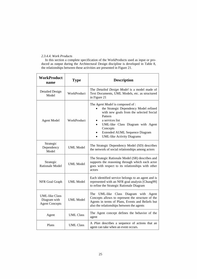
2.3.4.4. Work Products In this section a complete specification of the WorkProducts used as input or pro-
duced as output during the Architectural Design discipline is developed in Table 8, the relationships between these activities are presented in Figure 21.
WorkProductname Type Description
Detailed Design Model WorkProduct
The Detailed Design Model is a model made of Text Documents, UML Models, etc. as structured in Figure 21
Agent Model WorkProduct
The Agent Model is composed of : • the Strategic Dependency Model refined
with new goals from the selected Social Pattern
• a services list • UML-like Class Diagram with Agent
Concepts • Extended AUML Sequence Diagram • UML-like Activity Diagrams
Strategic Dependency
Model UML Model The Strategic Dependency Model (SD) describes
the network of social relationships among actors
Strategic Rationale Model UML Model
The Strategic Rationale Model (SR) describes and supports the reasoning through which each actor goes with respect to its relationships with other actors
NFR Goal Graph UML Model Each identified service belongs to an agent and is represented with an NFR goal analysis [Chung99] to refine the Strategic Rationale Diagram
UML-like Class Diagram with
Agent Concepts UML Model
The UML-like Class Diagram with Agent Concepts allows to represent the structure of the Agents in terms of Plans, Events and Beliefs but also the relationships between the agents
Agent UML Class The Agent concept defines the behavior of the agent
Plans UML Class A Plan describes a sequence of actions that an agent can take when an event occurs.
25

Events UML Class Events describe stimuli, emitted by agents or automatically generated, in response to which the agents must take action.
Beliefs UML Class A Belief describes a piece of knowledge that an agent has about itself and its environment.
Extended AUML Sequence Diagram
UML Model The Extended AUML Sequence Diagram allows to represent the communication between the agents
UML-like Activity Diagrams UML Model
The UML-like Activity Diagrams allows to represent the synchronization and the relationships between plans and events
The i* Modeling Framework Guidance
The i* Modeling framework is an ontology founded on the notions of actor, goal and social dependency that includes two models formalized with the intentional concepts from the BDI model
Detailed Design Framework for
Multi-Agent Systems
Guidance
The Detailed Design Framework for describing Multi-Agent Systems provides a guidance to select the most appropriate Social Pattern, to refine the models and to specify System Architecture with an ADL
Agent-UML Profile Guidance
The Agent Unified Modeling Language (AUML) Profile offers extensions to the Unified Modeling Language to represent the different dimensions of a Multi-Agent System.
Table 8. Detailed Design Work Products description
26

Detailed DesignModel
Services List
Detailed Design Frameworkfor Multi-Agent Systems
Strategic Dependency Model
Agent Model
UML Class Diagramwith Agent Concepts
AUML Sequence Diagram
UML Activity Diagram
Agent-UML Profile
Plans
EventsBeliefs
Agent
The i* Modeling Framework
Figure 21. Detailed Design Work Products relationships
2.3.5. Development During the development stage, the detailed design specification must be followed
step by step in order to implement the application and produce an executable release. To achieve it, an Agent-Oriented programming language as JACK [JACK] or JADEX [JADEX] is required.
2.3.5.1. Package As shown in Figure 22, the Development discipline involves three ProcessRoles,
four WorkProducts and a Guidance.
Development
JACK Intelligent AgentsProfile
Software Architect
User Interface Designer
Design Agents Structure ()
Draw User Interfaces ()
Agent Model User Interface PrototypesImplementable Model Executable Release
Developer
Implement BDI Agents ()
Develop User Interfaces ()
Figure 22. Development as a SPEM discipline
27

2.3.5.2. Work Definitions In this section the Work Definitions performed during the Development discipline
are presented. Figure 23 shows their workflow, for further refinements see Figure 24 and Table 9.
Model Structuration
User Interface Prototypes
Model Implementation
[New Iteration]
Implementable Model
Executable Release
[Existing Functionnalities Refinement]
[New Functionnalities]
Figure 23. Development Work Definitions
2.3.6.3. Workflow In this section a complete specification of the activities performed during the De-
velopment discipline is developed in Table 9, the workflow of these activities is pre-sented in Figure 24.
Design Agents Structure
: Software Architect : User Interface Designer
Draw User Interfaces
: Developer
Agent Model
Implement BDI Agents
Develop User Interfaces
User Interface Prototypes
Implementable Model
Executable Release
Model Structuration
Model Implementation
Figure 24. Development Workflow
28

N° Activity name Goal ProcessRole Pre Parent WorkDefinition
Output WorkProducts
1 Design Agents Structure
Based on the Agent Model developed during the Detailed Design discipline, a skeleton of the Agents that will be implemented in this discipline is designed or forward engineered
Sofware Archi-tect Model Structuration A Development
Model
2 Draw User Interfaces
The interfaces of the application being developed are sketched if they are new ones or refined if the previous ones were unsatisfying
User Interface Designer Model Structuration User Interface
Prototypes
3 Implement BDI Agents
Based on the generated skeleton the beliefs, desires and intentions of the agents are imple-mented
Developer Activity 1 and 2
Model Implementation Executable Release
4 Develop User Interfaces
User Interfaces are developed so that the application can be successfully exploited Developer Activity 1
and 2 Model
Implementation Executable Release
Table 9. Development activities description
29

2.3.5.4. Work Products In this section a complete specification of the WorkProducts used as input or pro-
duced as output during the Development discipline is developed in Table 10, the relationships between these activities are presented in Figure 25.
WorkProduct
Name Type Description
Development Model WorkProduct The Development Model is a model made of Text Documents, UML Models, etc. as structured in Figure 25
Agent Model WorkProduct See Detailed Design
Executable Release WorkProduct The Executable Release is an executable version of the application developed during the iteration that can be tested by stakeholders
Implementable Release WorkProduct
The Implementable Release is a generated skeleton of the application that needs to be implemented to become an Executable Release
User Interface Prototypes Text Document
The User Interface Prototypes is a text document with drawings of the user interfaces needed for the implementation of the requirements developed in the current iteration
JACK Intelligent Agents Guidance
JACK is an Agent-Oriented development environment designed to extend Java with the theoretical Belief-Desire-Intention (BDI) agent model. JACK’s agents can be consid-ered autonomous software components that have explicit goals to achieve or events to cope with (called desires). To describe how they should handle these desires, agents are programmed with a set of plans (the inten-tions). Each plan describes how to achieve a goal under different circumstances. Set to work, the agent pursues its given goals (de-sires), adopting the appropriate plans (inten-tions) according to its current set of data (be-liefs) about the state of the world.
Table 10. Development Work Products description
30

Agent Model
User Interface Prototypes Implementable Model
Executable Release
DevelopmentModel
JACK Intelligent AgentsProfile
Figure 25. Development Work Products relationships
2.3.6. Validation During the validation discipline, the level of quality of the product is evaluated
through statistical benchmarks. This involves not only the final phases but also early steps of the project including architecture validation. It continues through the valida-tion of the executable releases by users.
Tests involve different domains as: • component checking; • component integration checking; • requirements elicitation checking; • identification and checking that all the discovered failures are corrected be-
fore deployment.
2.3.6.1. Package As shown in Figure 20, the Validation discipline involves three ProcessRoles, four
WorkProducts and a Guidance.
Validation
Tester
Test Manager
Perform Test ()
Define Test Approach ()
End User
Provide Feed Beck on Application ()
Express New Requirements ()
Executable Release Test Policy
Testing Guideline
Validation Evaluation Test Report
Figure 26. Validation as a SPEM discipline
31

2.3.6.2. Work Definitions In this section the Work Definitions performed during the Validation discipline are
presented. Figure 27 shows their workflow, for further refinements see Figure 28 and Table 11.
Test Management Testing
[New Iteration]
Test Report
Test Policy Validation Evaluation
Figure 27. Validation Work Definitions
2.3.6.3. Workflow In this section a complete specification of the activities performed during the Vali-
dation discipline is developed in Table 11, the workflow of these activities is pre-sented in Figure 28.
Define Test Approach
Test Report
: Test Manager : Tester
Express New Requirements
[More End-Users to Test ][All End-Users Tested]
: End User
Perform Test
Provide Feed Back on Application
Executable Release
Review and Evaluate Results
Test Policy
Validation Evaluation
Test Management
Testing
Figure 28. Validation Workflow
32

N° Activity name Goal ProcessRole Pre Parent
WorkDefinition Output
WorkProducts
1 Define Test Approach
Based on the modules that need to be tested during the itera-tion, the stakeholders (end-users, etc.) implied in this valida-tion discipline are selected and the way the tests will be per-formed (the test policy) is chosen
Test Manager Test Management Test Policy
2 Perform Test The test policy defined in the previous activity by the Test Manager is applied by the Tester Tester Activity 1 Testing User Interface
Prototypes
3 Provide Feed
Back on Application
The End-User provides comments, critics, remarks on the modules of the application that are presented to him. The Tester writes them down and looks forward to further pro-posals
End User Activity 2 Testing Executable Release
4 Express New Requirement
s
The End-User often express functional requirements that the system should provide. The Tester writes them down so that they can be analyzed and implemented in the next iteration(s)
End User Activity 2 Testing Validation Evaluation
5 Review and
Evaluate Results
The validation discipline is very important in the context of spiral development, all the results must be carefully taken into account to feed the next iteration(s) with users feed backs/new requirements. The Test Manager reviews these results and writes the Validation Report.
Test Manager Activity 3 and 4 or
Activity 2 Test Management Validation Report
Table 11. Validation activities description
33

2.3.6.4. Work Products In this section a complete specification of the WorkProducts used as input or pro-
duced as output during the Validation discipline is developed in Table 12, the rela-tionships between these activities are presented in Figure 29.
WorkProduct
name Type Description
Validation Model WorkProduct
The Validation Model is a model made of Text Documents, UML Models, etc. as structured in Figure 29
Test Policy Text Document
The Test Policy is a text document describing who will be tested, how he will be tested and when he will be tested depending on the functional requirements being developed during that iteration
Test Report Text Document
The Test Report is a text document describing the reactions, remarks, ideas, … of the stakeholders facing the application developed during the iteration
Validation Evaluation
Text Document
The Validation Evaluation is a Text Document describing the modifications that need to be done to the developed application and the new requirements that need to be included in the system
Testing Guideline Guidance The Testing Guideline provides a guidance to select the most appropriate Test Policy for the current iteration
Table 12. Validation Work Products description
ValidationModel
Test Report
Test Policy
Testing Guideline
Validation Evaluation
Figure 29. Validation Work Products relationships
34
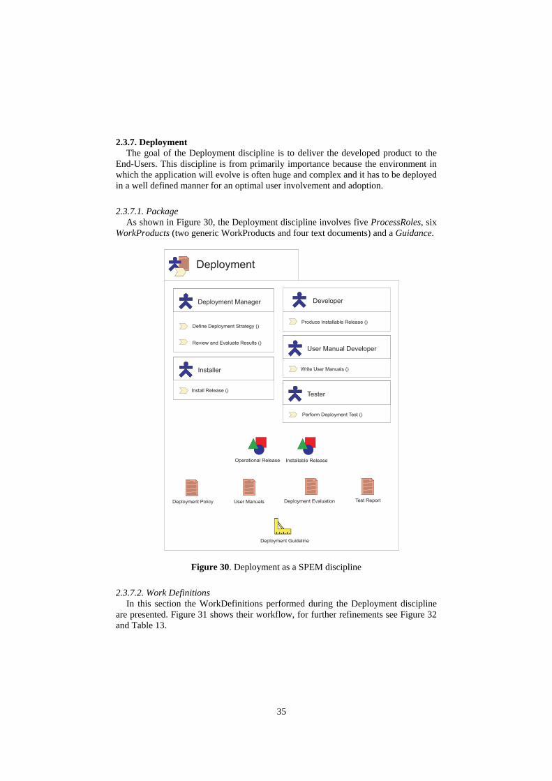
2.3.7. Deployment The goal of the Deployment discipline is to deliver the developed product to the
End-Users. This discipline is from primarily importance because the environment in which the application will evolve is often huge and complex and it has to be deployed in a well defined manner for an optimal user involvement and adoption.
2.3.7.1. Package As shown in Figure 30, the Deployment discipline involves five ProcessRoles, six
WorkProducts (two generic WorkProducts and four text documents) and a Guidance.
Deployment
User Manual Developer
Developer
Write User Manuals ()
Produce Installable Release ()
Deployment Manager
Define Deployment Strategy ()
Review and Evaluate Results ()
Deployment Guideline
Installable Release
Deployment Policy User Manuals
Operational Release
Deployment Evaluation
Installer
Install Release ()Tester
Perform Deployment Test ()
Test Report
Figure 30. Deployment as a SPEM discipline
2.3.7.2. Work Definitions In this section the WorkDefinitions performed during the Deployment discipline
are presented. Figure 31 shows their workflow, for further refinements see Figure 32 and Table 13.
35

Deployment Management Physical Deployment
[New Iteration]
Test Report
Deployment Policy Deployment Evaluation User Manuals
Figure 31. Deployment Work Definitions
2.3.7.3. Workflow In this section a complete specification of the activities performed during the De-
ployment discipline is developed in Table 13, the workflow of these activities is pre-sented in Figure 32.
Define DeploymentStrategy
Deployment Evaluation
: DeploymentManager
: Tester
Write User Manuals
: Developper
PerformDeployment Test
Produce Installable Release
Installable Release
Review and Evaluate Results
Deployment Policy User Manuals
Operational Release
: User ManualDeveloper
: Installer
Install Release
Test Report
DeploymentManagement
Physical Deployment
Figure 32. Deployment Workflow
36

N° Activity name Goal ProcessRole Pre Parent
WorkDefinition Output
WorkProducts
1 Define
Deployment Strategy
Based on the application to deploy, the environment in which it has to be deployed and the End-Users, a deployment strategy describ-ing how, when and by who the deployment will be performed
Deployment Manager Deployment
Management Deployment Policy
2 Produce
Installable Release
The Developer creates all the necessary material to perform the installation of the software, it results in an installable release Developer Activity
1 Physical Deployment Installable Release
3 Install Release
The Installable Release produced by the Developer is installed on site by the Installer Installer Activity
2 Physical Deployment Executable Release
4 Write User Manuals
The User Manual Developer writes all the documentation, policies, technical reviews, etc. useful for use of the application by each type of End-User
User Manual Developer
Activity 1 Physical Deployment User Manuals
5 Perform
Deployment Test
Deployment is a very tricky task and cannot be performed once for all, consequently, the result of each deployment effort has to be studied by the Tester
Tester Activity 3 and 4 Physical Deployment Test Report
6 Review and
Evaluate Results
Finally the Deployment Manager reviews tester’s results, compares the effort to the objectives of the deployment effort and writes the Deployment Report
Deployment Manager
Activity 5
Deployment Management
Deployment Evaluation
Table 13. Deployment activities description
37

2.3.7.4. Work Products In this section a complete specification of the WorkProducts used as input or pro-
duced as output during the Deployment discipline is developed in Table 14, the rela-tionships between these activities are presented in Figure 33.
WorkProduct
name Type Description
Deployment Model WorkProduct
The Deployment Model is a model made of Text Documents, UML Models, etc. as structured in Figure 33
Deployment Policy
Text Document
The Deployment Policy is a text document describing where, how and when the software application will be deployed
Installable Release WorkProduct
The Installable Release is a version of the application containing all the material to deploy the software in the organization as well as all the User Manuals and documentation to use this software
Executable Release WorkProduct See Development
User Manuals Text Document
User Manuals include all the documentation, policies, … needed for each type of user
Test Report Text Document
The Test Report is a text document describing the reactions, remarks, ideas, … of the stakeholders facing the application deployed during the iteration
Deployment Evaluation
Text Document
The Deployment Evaluation is a Text Document describing the modifications that need to be done to the deployed application and the features of the system that needs to be further documented
Deployment Guideline Guidance
The Deployment Guideline provides a guid-ance to select the most appropriate Deploy-ment Policy for the current iteration
Table 14. Deployment Work Products description
38

DeploymentModel
Deployment Guideline
Test Report
Installable Release
Deployment Policy
User Manuals
Executable Release
Deployment Evaluation
Figure 33. Deployment Work Products relationships
2.3.8. Risk and Project Management Following [Kruchten03], “software project management is the art of balancing
competing objectives, managing risk, and overcoming constraints to deliver a prod-uct that meets the needs of the customers (the ones who pay the bill) and the end users.”
The Risk and Project Management discipline has the following purposes: • providing a framework for managing software-intensive projects; • providing practical guidelines for planning, staffing, executing, and monitor-
ing projects; • providing a framework for managing risk.
2.3.8.1. Package As shown in Figure 34, the Risk and Project Management discipline involves one
ProcessRole and three WorkProducts (all of them are text documents).
Risk and Project Management
Project Manager
Fix Project Scope ()
Plan the Project ()
Identify and Evaluate Risks ()
Fix Iteration Objectives ()
Iteration Evaluation
Manage Activities and Human Ressources ()
Evaluate Iteration ()
Deployment EvaluationValidation Evaluation
Figure 34. Risk and Project Management as a SPEM discipline
39

2.3.8.2. Work Definitions In this section the Work Definitions performed during the Risk and Project Man-
agement discipline are presented. Figure 35 shows their workflow, for further refine-ments see Figure 36 and Table 15.
Project Definition Iteration Management
[New Iteration]
[Existing Project][New Project]
Current Iteration Evaluation
Validation EvaluationDeployment Evaluation
Previous Iteration Report
Figure 35. Risk and Project Management Work Definitions
2.3.8.3. Workflow In this section a complete specification of the activities performed during the Risk
and Project Management discipline is developed in Table 15, the workflow of these activities is presented in Figure 36.
Fix Project Scope
: Project Manager
Plan the Project
[Existing Project]
Identify and Evaluate RisksFix Iteration Objectives
Manage Activities and Human Ressources
Evaluate Iteration
[New Project]
Current Iteration Evaluation
Previous Iteration Report
Validation Evaluation Deployment Evaluation
Project Definition Iteration Management
Figure 36. Risk and Project Management Workflow
40

N° Activity name Goal ProcessRole Pre Parent
WorkDefinitionOutput
WorkProducts
1 Fix Project Scope
Facing a new project, the Project Manager has to delimit (in accordance with the stakeholders) as clearly as possible the scope of the work that has to be done. Determining the major risk features so that they can be resolved early on in the project is also from primarily importance at this stage
Project Manager Project Definition
2 Plan the Project
Once the scope of the project has been fixed it is necessary to plan roughly the efforts that must be done in terms of phases, iterations and disciplines. These two first activities cannot be performed once for all and will be refined later in the project due to the nature of iterative development
Project Manager Activity 1 Project Definition
3 Identify and
Evaluate Risks
The previously identified risk features and the newly identified ones are evaluated so that the Project Manager can determine which ones are already resolved, which ones can be resolved during this iteration and which ones cannot
Project Manager Activity 2 or Activity 0
Iteration Management
4 Fix Iteration Objectives
Based on the global scope of the project and the results of the previous iteration(s), the objectives of the current iteration are determined Project Manager Activity 2 or
Activity 0 Iteration
Management
5
Manage Activities
and Human Resources
Once the objectives have been fixed and the risk features identified and evaluated the iteration is started and the Project Manager has to manage the activities and coordinate the human resources to achieve the fixed goal
Project Manager Activity 3 and 4
Iteration Management
6 Evaluate Iteration
At the end of the iteration, the Project Manager evaluates the iteration results, checks whether the fixed objectives are met and whether the risky features are resolved
Project Manager Activity 5 Iteration Management Iteration Evaluation
Table 15. Risk and Project Management activities description
41

2.3.8.4. Work Products In this section a complete specification of the WorkProducts used as input or pro-
duced as output during the Risk and Project Management discipline is developed in Table 15, the relationships between these activities are presented in Figure 37.
WorkProduct
name Type Description
Risk and Project Management
Model WorkProduct
The Risk and Project Management Model is a model made of Text Documents, UML Models, etc. as structured in Figure 37
Validation Evaluation
Text Document See Validation
Deployment Evaluation
Text Document See Deployment
Iteration Evaluation
Text Document
The Iteration Evaluation is a Text Document describing the work done during the iteration, whether the iteration has fulfilled all the objectives, the features discovered during the iteration and finally the features to plan and the objectives of the next iteration
Table 15. Risk and Project Management WorkProducts description
Risk and Project ManagementModel Iteration Evaluation
Deployment Evaluation
Validation Evaluation
Figure 37. Risk and Project Management Work Products relationships
2.4 Work Product Dependency
Diagram in Figure 38 describes the dependencies among the S-Tropos process WorkProducts. For instance, the System Architecture Specification depends on both the Strategic Dependency Diagram and the Strategic Rationale Diagram since the systems actors as well as their intentions are developed in those two diagrams.
42

Stakeholders Intentions List
Strategic Dependency Model Strategic Rationale Model
Stakeholders List
Actors List
Actors Intentions List
System Architecture Specification
Services List
UML Class Diagramwith Agent Concepts
AUML Sequence Diagram UML Activity Diagram
User Interface Prototypes
Implementable Model
Executable Release
Test Report
Test Policy
Validation Evaluation
Deployment Policy
User Manuals
Deployment Evaluation
Iteration Evaluation
Figure 38. Work Products Dependency
2.5 S-Tropos Roles
The diagram in Figure 39 shows the different roles implied in the S-Tropos proc-ess as well as their hierarchy. For instance the Agent Designer is a specialization of a Designer.
Stakeholder
End User
Designer
System Specifier
Developer
User ManualDeveloper
Agent Designer
Software Architect
User InterfaceDesigner
Manager
Deployment Manager Test Manager Project Manager
Tester
Requirements Engineer
Installer
Analyst
Functional Analyst System Analyst
Figure 39. The S-Tropos process roles
43

3 Conclusion and Future Work
Agent-oriented modeling is a still under development discipline. Its success comes, as for object-oriented modeling, from the fact that it better meet the increasing com-plexity and flexibility required to develop software applications built in open-networked environments and deeply embedded into human activities. Nevertheless, the emergence of a new research program6 does not mean that it will directly be putted into practice by IT professionals. Indeed, it needs standardization, productivity gains, proven efficiency on huge and complex user-interactive software development projects, well-designed development frameworks, etc. for the software market to review its standards. Object-Orientation has also taken a long time to impose itself but thanks to the benefits it offers compared to the previous approaches it has become the actual reference. To follow the same evolution, agent-orientation has firstly to reach unification in concepts and terminology. In a second stage, the MAS develop-ment methodologies need to adapt and/or adopt the software engineering best prac-tices (see [Kruchten03]) and grow to a process capable of managing huge user-interactive software projects. Finally, it has to offer devices such as CASE Tools and knowledge bases to support software development and to allow IT professionals to easily and efficiently deal with the methodology.
The purpose of this paper has been to furnish a complete specification of an agent-
oriented spiral development process called S-Tropos using the SPEM notation. This process recycles the standard waterfall Tropos disciplines (Early Requirements, Late Requirements, Architectural Design and Detailed Design) but also four new ones (Development, Validation, Deployment and Risk and Project Management) complet-ing the process in order to dispose of a methodology able to deal with the whole spi-ral life cycle of an agent-oriented software development.
The S-Tropos methodology should now to be validated on a case study: current
work is done on a cooking plant production planning software of a steel company called Carsid. The steel industry is by essence an Agent-Oriented world. Factories as a cooking plant or a blast furnace are made of hundreds of different types of agents: software agents, machines, automates, humans, sensors, releases, effectors, control-lers, pyrometers, mobile devices, conveying belts, etc. That’s why agent-oriented models of those plants leading to the development of an agent-oriented application can provide advantages to the company especially in domains like information man-agement, process automation, resource and production planning, decision making, etc. A CASE Tool supporting the design all the models defined in the methodology but also offering advanced software engineering capabilities is also under develop-ment.
6 We consider Agent-Orientation as well as Object-Orientation as Lakatosian “research pro-
grams” rather than Kuhnian paradigms (see [Schinckus06]).
44

References
[AUML] FIPA, “Agent UML”, http://www.auml.org/. [Bastos03] L. Bastos, J. Castro, J. Mylopoulos, Integrating Organizational Requirements and
Socip-Intentional Architectural Styles, in Proceedings of Second International Workshop From Software Requirements to Architectures (STRAW’03), Portland, USA, May 9, 2003.
[Bernon02] C. Bernon, M.-P. Gleizes, S. Peyruqueou, G. Picard, “ADELFE, a Methodology
for Adaptive Multi-Agent Systems Engineering”, In Third International Workshop on Engi-neering Societies in the Agents World (ESAW), Madrid, September 2002.
[Boehm88] B. Boehm, “A Spiral Model of Software Development and Enhancement”, Com-
puter, May 1988, pp. 61-72. [Boehm94] B. Boehm, “A Collaborative Spiral Software Process Model Based on Theory W”,
IEEE CS Press, Los Alamitos, Calif., 1994, pp. 59-68. [Boehm96] B. Boehm, “Anchoring the Software Process”, IEEE Software, Volume 13, No 4,
July 1996, pp. 73-82. [Boehm00a] B. Boehm edited by Wilfred J. Hansen, “Spiral Development : Experience, Prin-
ciples, and Refinements”, Spiral Development Workshop February 9, 2000, July 2000. [Boehm00b] Barry Boehm, “Requirements that Handle IKIWISI, COTS, and Rapid Change”
Computer, IEEE, July 2000, pp. 99-102. [Booch99] G. Booch, J. Rumbaugh, and I. Jacobson, "The Unified Modeling Language User
Guide", Addison-Wesley Object Technology Series, 1999. [Burrafato02] P. Burrafato, M. Cossentino, “Designing a multi-agent solution for a bookstore
with the PASSI methodology", In Proceedings of the Fourth International Bi-Conference Workshop on Agent-Oriented Information Systems (AOIS-2002), Toronto (Ontario, Canada), 27-28 May 2002.
[Castro02] J. Castro, M. Kolp and J. Mylopoulos. “Towards A Requirements-Driven Develop-
ment Methodology : The Tropos Project,” In Information Systems, Elsevier, 2002. [Cossentino03] M. Cossentino, L. Sabatucci, V. Seidita, “SPEM description of the PASSI
process”, ICAR-CNR Technical report. December 2003. [Chung99] L. Chung, B. A. Nixon, E. Yu and J. Mylopoulos, “Non-Functional Requirements
in Software Engineering”, Kluwer Aceademic Publishers, 1999. [Do03] T. T. Do, M. Kolp and A. Pirotte. “Social Patterns for Designing Multi-Agent Sys-
tems”, In Proceedings of the 15thInternational Conference on Software Engineering and Knowledge Engineering (SEKE 2003), San Francisco, USA, July 2003.
45

[Donnay86/03] A. Donnay, F. Fouss, M. Kolp, D. Massart, T. T. Do, S. Faulkner and A. Pi-rotte, “Modélisation Orienté-Objet de la cokerie de Carsid”, Working Paper IAG 86/03, Université Catholique de Louvain, March 2003.
[Donzelli02] P. Donzelli, R. Setola, “Handling the knowledge acquired during the requirements
engineering process”, In Proceedings of the Fourteenth International Conference on Knowledge Engineering and Software Engineering (SEKE), 2002.
[Dorfman97] M. Dorfman, “Requirements Engineering”, In R. H. Thayer and M. Dorfman
(eds) “Software Requirements Engineering, Second Edition”. IEEE Computer Society Press, 1997, pp 7-22.
[Faulkner05] S. Faulkner, M. Kolp and P-Y. Schobbens, “An Architectural Description Lan-
guage for BDI Multi-Agent Systems”, submitted to International Journal of Autonomous Agents and Multi-Agent Systems (JAAMAS), Kluwer, 2005.
[FIPA05] Foundation for Intelligent Agents, http://www.fipa.org/. [Forsberg97] K. Forsberg and H. Mooz “System engineering overview” In R. H. Thayer and
M. Dorfman (eds.) “Software Requirements Engineering, Second Edition”, IEEE Computer Society Press, 1997, pp.44-72.
[Garro04] A. Garro, and M.P. Huget, and P. Turci, “Expressing GAIA Methodology using
SPEM (Software Process Engineering Meta-Model”, FIPA Methodology Technical Com-mittee, 2004.
[Gleizes03] M.-P. Gleizes, T. Millan and G. Picard, “ADELFE: Using SPEM Notation to
Unify Agent Engineering Process and Methodology”, Rapport interne IRIT no IRIT/2003-10-R, June 2003.
[JACK] JACK Intelligent Agents, http://www.agent-software.com/. [Jacobson99] I. Jacobson, G. Booch, J. Rumbaugh, “The Unified Software Development Proc-
ess”, Addision-Wesley, 1999. [Jacobson00] I. Jacobson, S. Bylund, “The Road to the Unified Software Development Proc-
ess”, Cambridge University Press, 2000. [JADEX] JADEX BDI Agent System,
http://vsis-www.informatik.uni-hamburg.de/projects/jadex/ [Jureta05] I. Jureta, M. Kolp, S. Faulkner, Y. Wautelet, “A Goal-Oriented Framework for
Business Modeling”, Working Paper IAG 126/04, Université Catholique de Louvain, Janu-ary 2005.
[Kolp05] M. Kolp, T. Do and S. Faulkner, “ A Social Driven Design of E-Business Systems”,
In R. Choren, A. Garcia, C. Lucena and A. Romanovsky (Eds.), “Software Engineering for Multi-Agent Systems III: Research Issues and Practical Applications, Springer, 2005.
[Kruchten03] P. Kruchten, “The Rational Unified Process : An Introduction”, Longman (Wok-
ingham), Addison-Wesley, December 2003.
46

[OME] Organization Modeling Environment, http://www.cs.toronto.edu/km/ome/. [OMG] Object Management Group, http://www.omg.org/. [Royce70] W. Royce, “Managing the Development of Large Software Systems”, Proceedings
of the IEEE WESCON, August 1970, pp. 1-9. [Royce98] W. Royce, “Software Project Management. A Unified Framework”, Addison-
Wesley, 1998. [Rumbaugh99] J. Rumbaugh, G. Booch, and I. Jacobson, "The Unified Modeling Language
Reference Manual", Addison-Wesley Object Technology Series, 1999. [RUP] IBM, “The Rational Unified Process. Version 2003.06.00.65”, Rational Software Cor-
poration, 2003. [Schinckus06] C. Schinckus, Y. Wautelet and M. Kolp, “Multi-Agent Spiral Software Engi-
neering: a lakatosian approach”, Cahiers du CEREC, 2006. [SPEM] OMG, “The Software Process Engineering Metamodel Specification. Version 1.1”,
January 2005. [UML] OMG, “OMG Unified Modeling Language Specification. Version 1.5”, March 2003. [Wautelet109/04] Y. Wautelet, L. Louvigny, M. Kolp, “Le Unified Process comme méthodo-
logie de gestion de projet informatique. Eléments d'application en milieu sidérurgique”, Working Paper IAG 109/04, Université Catholique de Louvain, 2004.
[Wautelet111/04] Y. Wautelet, L. Louvigny, M. Kolp, “Modélisation Orienté-Objet d'aspects
opérationnels de base de données sidérurgique”, Working Paper IAG 111/04, Université Ca-tholique de Louvain, 2004.
[Weiss99] G. Weiss, “Multiagent Systems: A Modern Approach to Distributed AI”, The MIT
Press, 1999. [Wooldridge95] M. Wooldridge and N.R Jennings, “Intelligent agents: Theory and practice”,
The knowledge Engineering Review, 10(2): 115-152, 1995. [Wooldridge00] M. Wooldridge, N.R. Jennings, D. Kinny, “The Gaia Methodology for Agent-
Oriented Analysis and Design”, JAAMAS Vol. 3. No. 3, 2000, pp. 285-312 [XML] W3C, “Extensible Markup Language (XML) 1.0 (Third Edition)”, February 2004. [Yu95] E. Yu. “Modeling Strategic Relationships for Process Reengineering”, PhD thesis,
University of Toronto, Department of Computer Science, Canada, 1995.
47