unconstrained 2d to stereoscopic 3d image and video conversion using semi-automatic energy...
TRANSCRIPT
Unconstrained 2D to Stereoscopic 3D Image and Video Conversion using Semi-Automatic Energy Minimization Techniques
Raymond Phan, Richard Rzeszutek and Dimitrios Androutsos Dept. of Electrical & Computer Engineering Ryerson University – Toronto, Ontario, Canada
Thursday, October 24th, 2012 Chinese 6 Theatre – Hollywood, California, USA
© 2012 SMPT E · T he 2012 Annual Technical C onference & Exhibition · www.smpte2012.org
Outline of Presentation • Introduction & Motivation • Conversion Framework for Images
– Random Walks – Graph Cuts / Depth Priors
• Conversion Framework for Video – Keyframes to Label – Label Tracking
• Results – Images and Videos
© 2012 SMPT E · T he 2012 Annual Technical C onference & Exhibition · www.smpte2012.org
Introduction • Creating stereoscopic content from single-
view footage / 2D to 3D Conversion – Huge surge of popularity: Converting legacy
content is very appealing – Current accepted method is quite accurate, but
very labor intensive and difficult – Known as rotoscoping: Manual operators extract
objects in a single frame to create left-right views – Much research in 2D to 3D conversion performed
to alleviate difficulty, minimize time & cost
© 2012 SMPT E · T he 2012 Annual Technical C onference & Exhibition · www.smpte2012.org
Introduction – (2) • Goal of 2D to 3D Conversion: Depth Map
– B & W image showing depth at each point – Depth maps are the main tool for conversion
• Ultimate Goal: Automatic Conversion – Most methods concentrate here – Problem: Errors cannot be easily corrected – May require extensive pre/post-processing
• Solution? Semi-Automatic – Happy medium between auto & manual
© 2012 SMPT E · T he 2012 Annual Technical C onference & Exhibition · www.smpte2012.org
Motivation • Semi-auto: Some user effort, rest is automatic
– User marks objects/regions in the image on what is close/far from camera (dark/light intensities or colors)
– For video: Mark several keyframes • Allow for label propagation from first frame minimizing user effort
– Using above info, goal is to solve for the other depths in the entire image, or entire video
– Results: Single depth map or a sequence of them • How do we solve?
– Using mixture of two semi-automatic segmentation algorithms: Random Walks & Graph Cuts
© 2012 SMPT E · T he 2012 Annual Technical C onference & Exhibition · www.smpte2012.org
Conversion Framework – Images • Random Walks: Energy Minimization Scheme
– Starting from a user-defined label, what is the likelihood of a random walker visiting all unlabeled pixels in image
– Goal: Classify every pixel to belong to one of K labels – Pixel gets the label generating the highest likelihood
• Modify Random Walks to create depth maps – Likelihoods are probabilities: Spans the set [0,1] – User-defined depths and solved depths spans same set – Goal is to solve for one label: The depth!
© 2012 SMPT E · T he 2012 Annual Technical C onference & Exhibition · www.smpte2012.org
Conversion Framework – Images – (2) – Use Scale-Space Random Walks in our framework
• Pyramidal sampling scheme, with Random Walks applied to each resolution Merged via Geometric Mean
– User chooses values from [0,1] and brushes over image – 0: Dark intensity / color, 1: Light intensity / color – Resulting solved probabilities are directly used as depths
• Is this valid? – Yes! Psych. study done at Tel Aviv Uni. in Israel – As long as the user is perceptually consistent in marking
© 2012 SMPT E · T he 2012 Annual Technical C onference & Exhibition · www.smpte2012.org
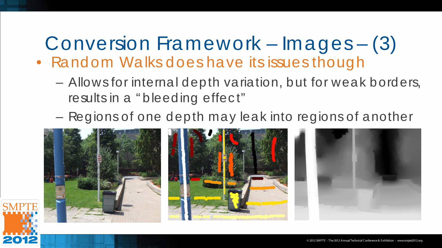
Conversion Framework – Images – (3) • Random Walks does have its issues though
– Allows for internal depth variation, but for weak borders, results in a “bleeding effect”
– Regions of one depth may leak into regions of another
© 2012 SMPT E · T he 2012 Annual Technical C onference & Exhibition · www.smpte2012.org
Conversion Framework – Images – (4) • Internal depth variation = Good!
– Minimizes cardboard cutout effect – RW generates depths not originally defined by user – But, we need to respect object boundaries
• Idea: Combine Random Walks with Graph Cuts – Graph Cuts = Hard Segmentation
• Only creates result with depths/labels provided by user – GC solves the MAP-MRF problem with user labels – Consider image as a weighted connected graph
• Solution is to solve the max-flow/min-cut of this graph
© 2012 SMPT E · T he 2012 Annual Technical C onference & Exhibition · www.smpte2012.org
Conversion Framework – Images – (5) • NB: Making depth maps = Segmentation Problem
– Specifically, a multi-label segmentation problem – But! Graph Cuts: Binary segmentation problem (FG/BG) – Graph Cuts also has an integer labeling, not from [0,1]
• Must modify above to become multi-label – Each unique user-defined label is given an integer label – Binary segmentation is performed for each label
• FG: Label in question, BG: All of the other labels – Rest of the pixels are those we wish to label
© 2012 SMPT E · T he 2012 Annual Technical C onference & Exhibition · www.smpte2012.org
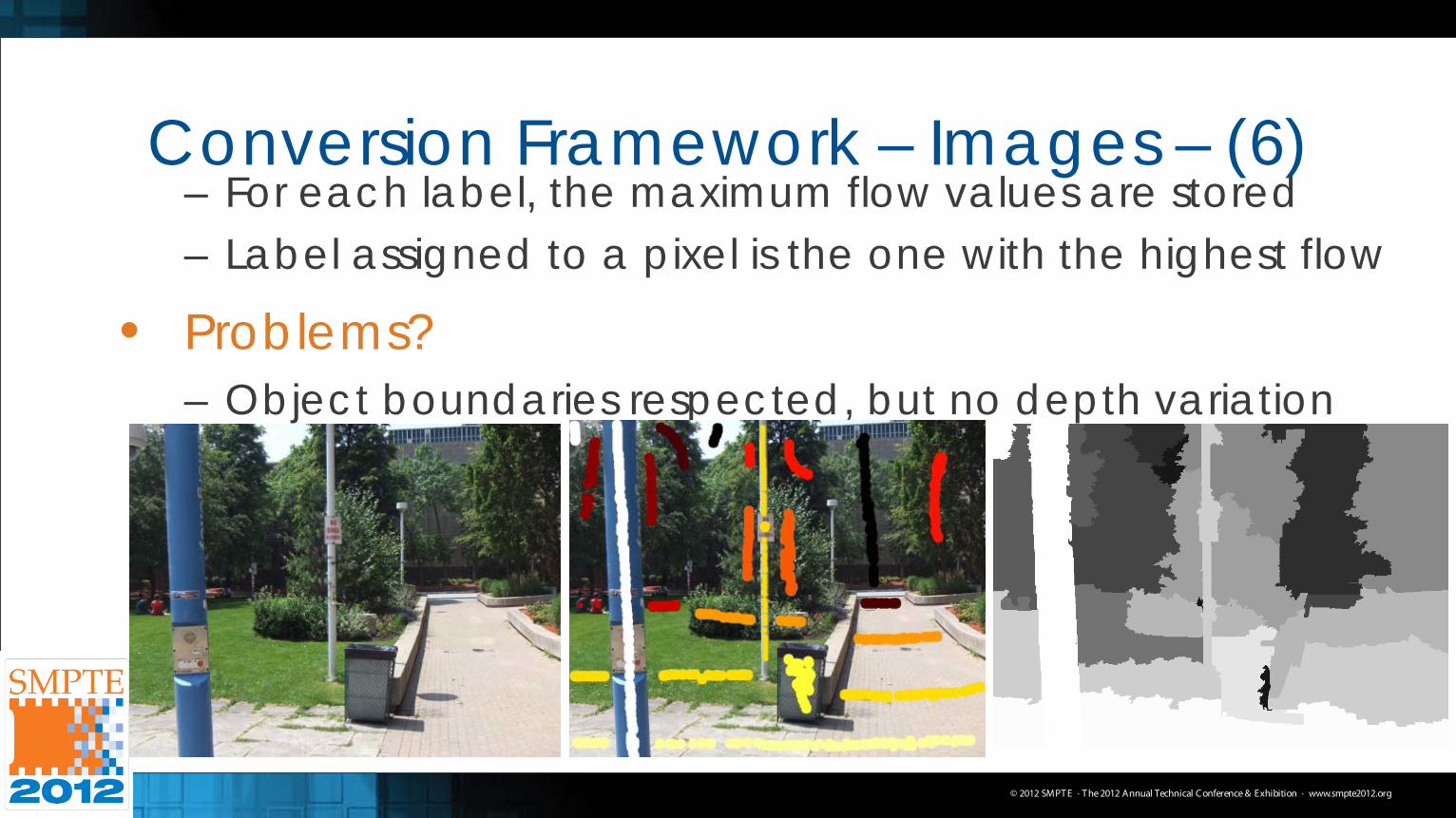
Conversion Framework – Images – (6) – For each label, the maximum flow values are stored – Label assigned to a pixel is the one with the highest flow
• Problems? – Object boundaries respected, but no depth variation
© 2012 SMPT E · T he 2012 Annual Technical C onference & Exhibition · www.smpte2012.org
Conversion Framework – Images – (7) • But! We can make use of this
– Merge Random Walks & Graph Cuts together – Create a depth prior: An initial depth map estimate – This is essentially Graph Cuts! – We merge by feeding depth prior as additional information into RW
• Before we merge… – Depth maps for RW and GC must be compatible with each other
• RW has depths of [0,1], GC has integer labels
– Map the user-defined labels from RW of set [0,1] to an integer set – Perform Graph Cuts on using this integer set, and map the integer
set back to the set of [0,1] Use a lookup table to do this
© 2012 SMPT E · T he 2012 Annual Technical C onference & Exhibition · www.smpte2012.org
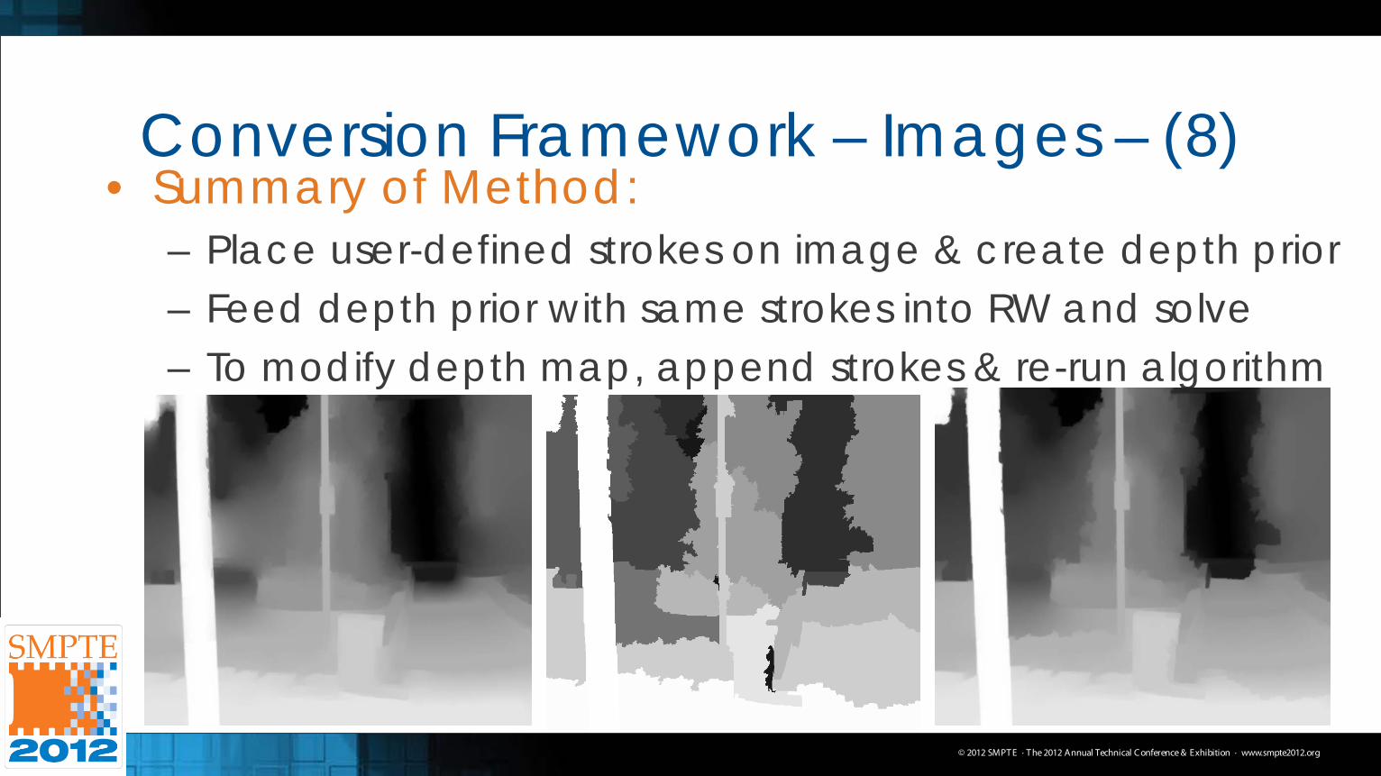
Conversion Framework – Images – (8) • Summary of Method:
– Place user-defined strokes on image & create depth prior – Feed depth prior with same strokes into RW and solve – To modify depth map, append strokes & re-run algorithm
© 2012 SMPT E · T he 2012 Annual Technical C onference & Exhibition · www.smpte2012.org
Conversion Framework – Video • Essentially the same as images, but we need to:
– Mark more than one image / keyframe • Result will be a sequence of depth maps
– Assume no abrupt changes in video • If there are, separate manually, or use shot detection
• Also must be aware of memory constraints – Intuitive to process each frame individually
• Fits well with memory, and can compute depth maps in parallel • However, this breaks temporal relationship Flickering
– Ideal to process all frames simultaneously in memory • But this will exhaust all available memory!
© 2012 SMPT E · T he 2012 Annual Technical C onference & Exhibition · www.smpte2012.org
Conversion Framework – Video – (2) • How do we solve?
– Use block processing to preserve temporal coherency – Process blocks of frames without exhausting memory – Overlapping frames within blocks are left unused
• Each block is independent of the others
• Back to labeling: How many frames do we label? – We allow the user the option of manually choosing
which ones to label – However, labeling only a small set of frames will result in
depth artifacts
© 2012 SMPT E · T he 2012 Annual Technical C onference & Exhibition · www.smpte2012.org
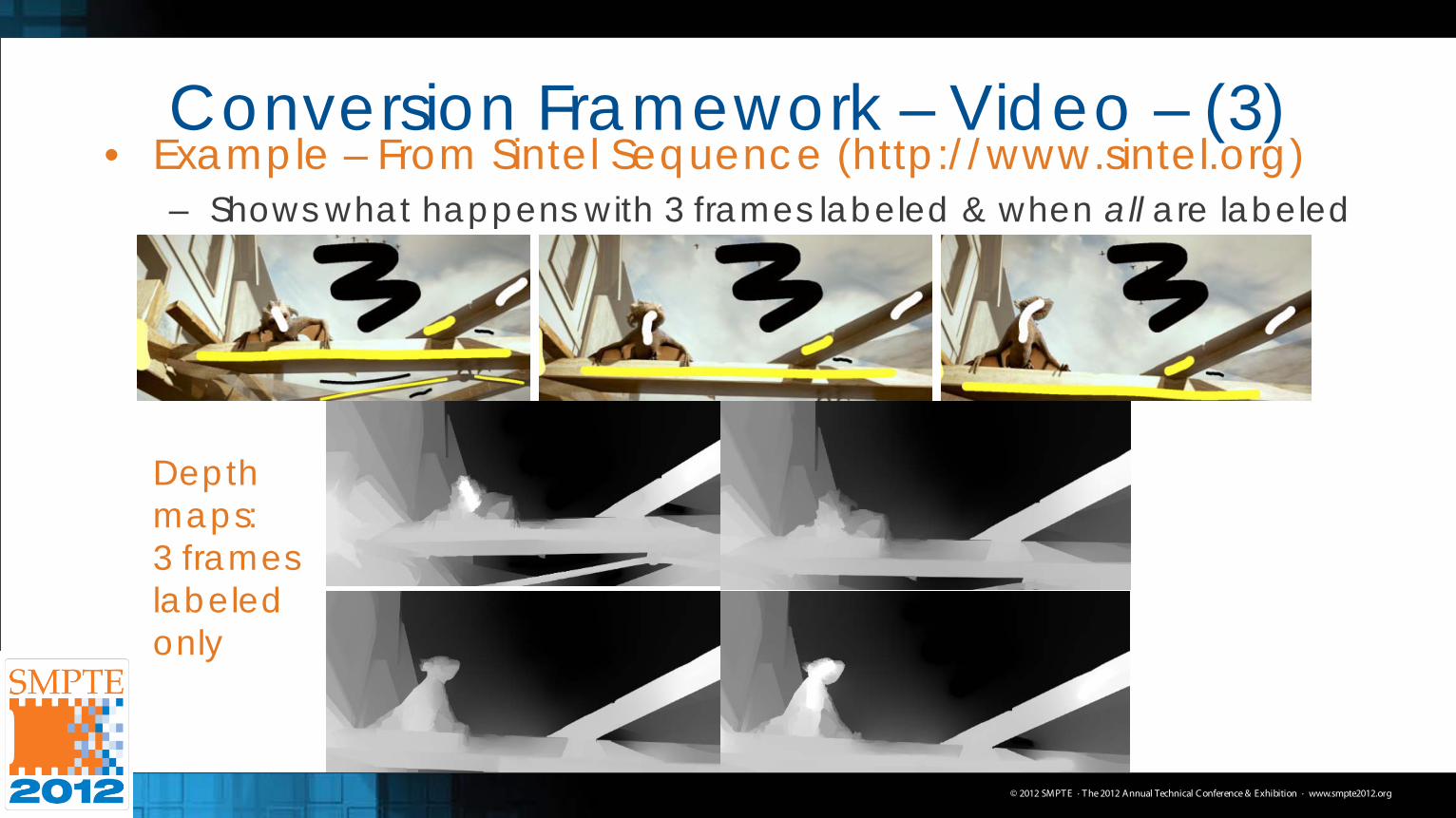
Conversion Framework – Video – (3) • Example – From Sintel Sequence (http://www.sintel.org)
– Shows what happens with 3 frames labeled & when all are labeled
Depth maps: 3 frames labeled only
© 2012 SMPT E · T he 2012 Annual Technical C onference & Exhibition · www.smpte2012.org
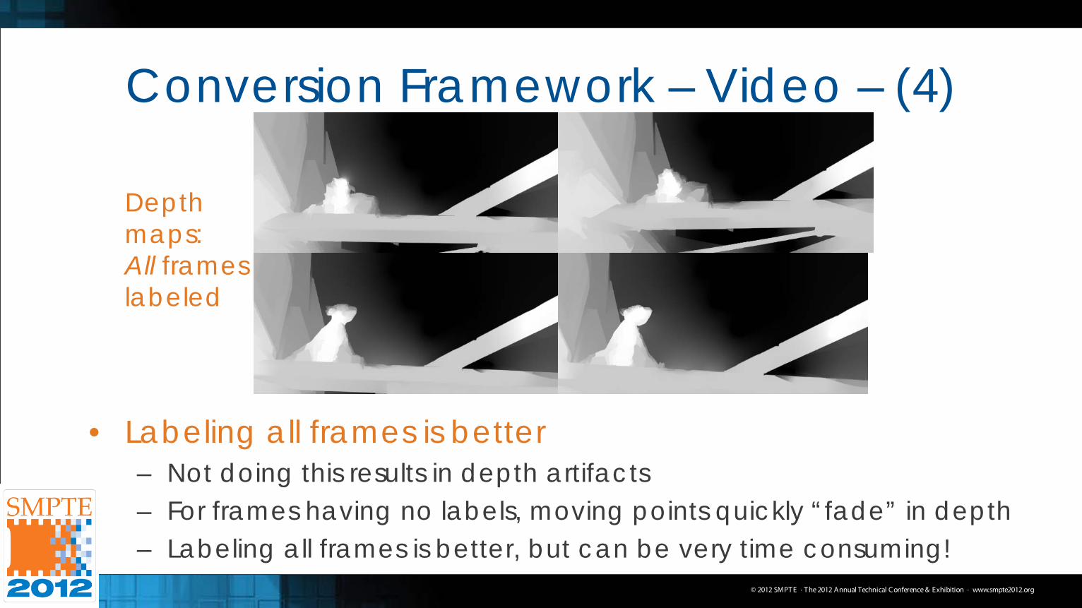
Conversion Framework – Video – (4)
Depth maps: All frames labeled
• Labeling all frames is better – Not doing this results in depth artifacts – For frames having no labels, moving points quickly “fade” in depth – Labeling all frames is better, but can be very time consuming!
© 2012 SMPT E · T he 2012 Annual Technical C onference & Exhibition · www.smpte2012.org
Conversion Framework – Video – (5) • Labeling all frames is better – Part II
– Instead of manually labeling all frames, label first frame and use a tracking algorithm to propagate the labels
– Adjust depths of labels when object depths change • Label Tracking?
– Would be very taxing to track all points in a stroke – Decompose a stroke at a particular depth into N points – Track each of these points separately – Reconstruct the stroke using spline interpolation
© 2012 SMPT E · T he 2012 Annual Technical C onference & Exhibition · www.smpte2012.org
Conversion Framework – Video – (6) • Tracker used: Tracking-Learning-Detection (TLD)
– Long term tracker for unconstrained video by Kalal et al. – Simply draw a bounding box around object in first frame – After, trajectory is determined for the rest of the frames,
accounting for size and illumination changes • How do we use this?
– For each point in each decomposed stroke, surround a bounding box and track the region
– Reconstruct each stroke using the tracked points
© 2012 SMPT E · T he 2012 Annual Technical C onference & Exhibition · www.smpte2012.org
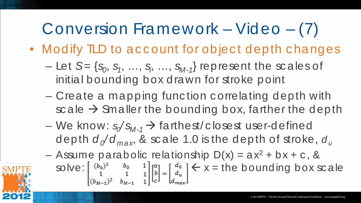
Conversion Framework – Video – (7) • Modify TLD to account for object depth changes
– Let S = {s0, s1, …, si, …, sM-1} represent the scales of initial bounding box drawn for stroke point
– Create a mapping function correlating depth with scale Smaller the bounding box, farther the depth
– We know: s0/sM-1 farthest/closest user-defined depth d0/dmax, & scale 1.0 is the depth of stroke, du
– Assume parabolic relationship D(x) = ax2 + bx + c, & solve: x = the bounding box scale
© 2012 SMPT E · T he 2012 Annual Technical C onference & Exhibition · www.smpte2012.org
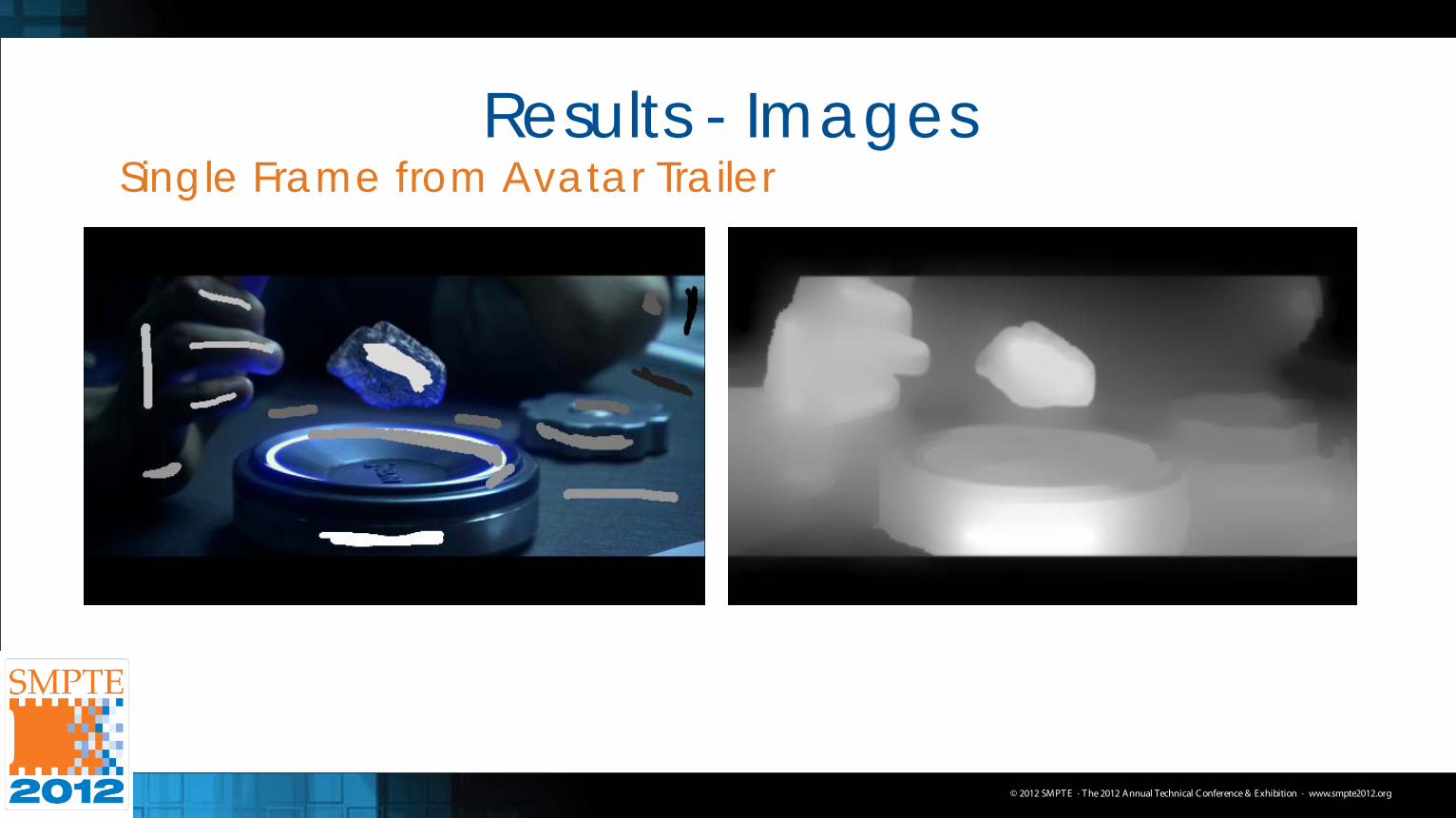
Results - Images Single Frame from Avatar Trailer
© 2012 SMPT E · T he 2012 Annual Technical C onference & Exhibition · www.smpte2012.org
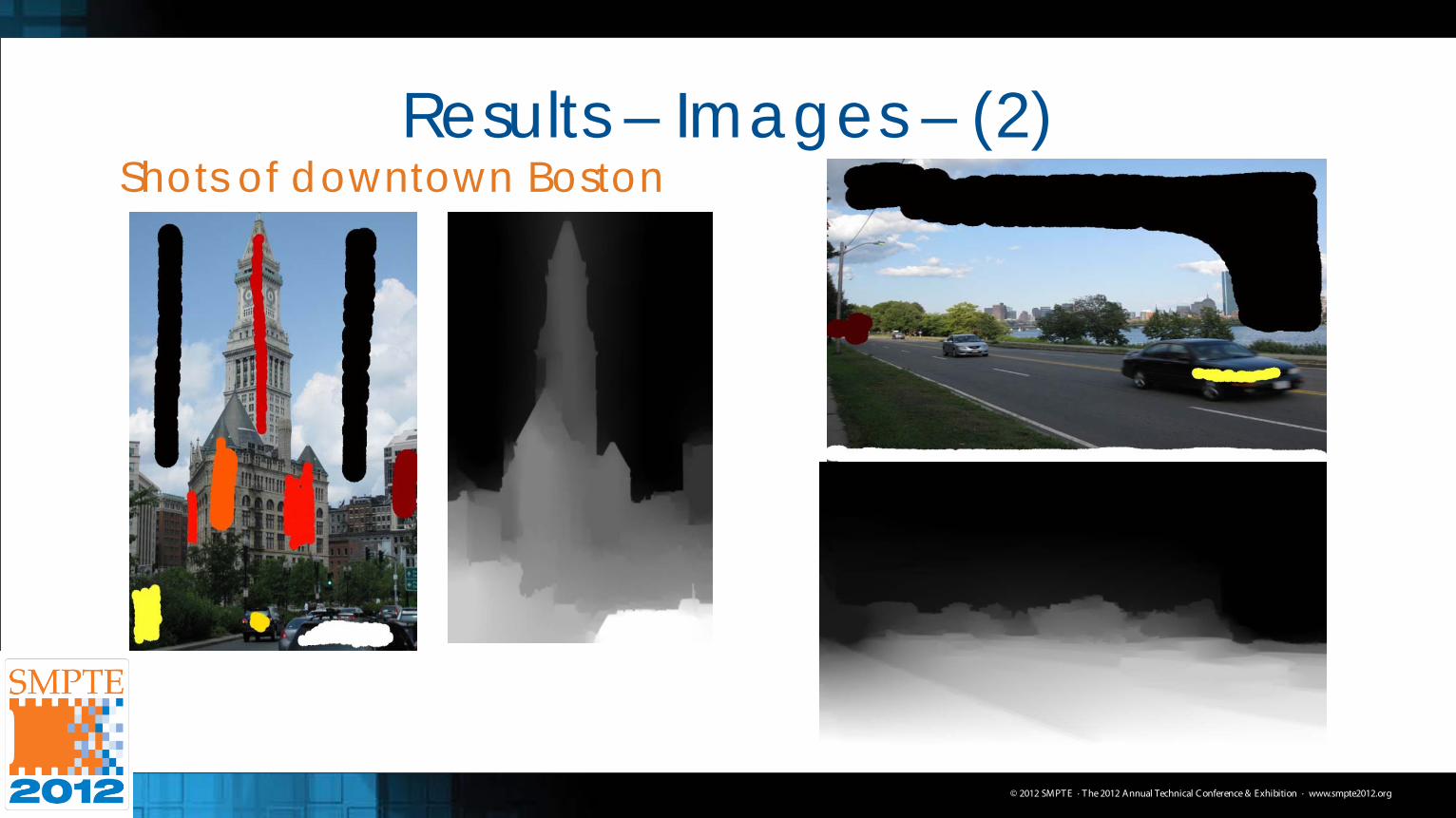
Results – Images – (2) Shots of downtown Boston
© 2012 SMPT E · T he 2012 Annual Technical C onference & Exhibition · www.smpte2012.org
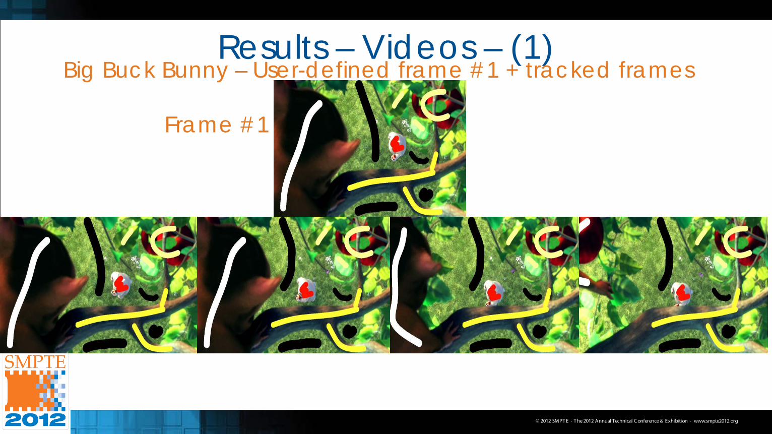
Results – Videos – (1) Big Buck Bunny – User-defined frame #1 + tracked frames
Frame #1
© 2012 SMPT E · T he 2012 Annual Technical C onference & Exhibition · www.smpte2012.org
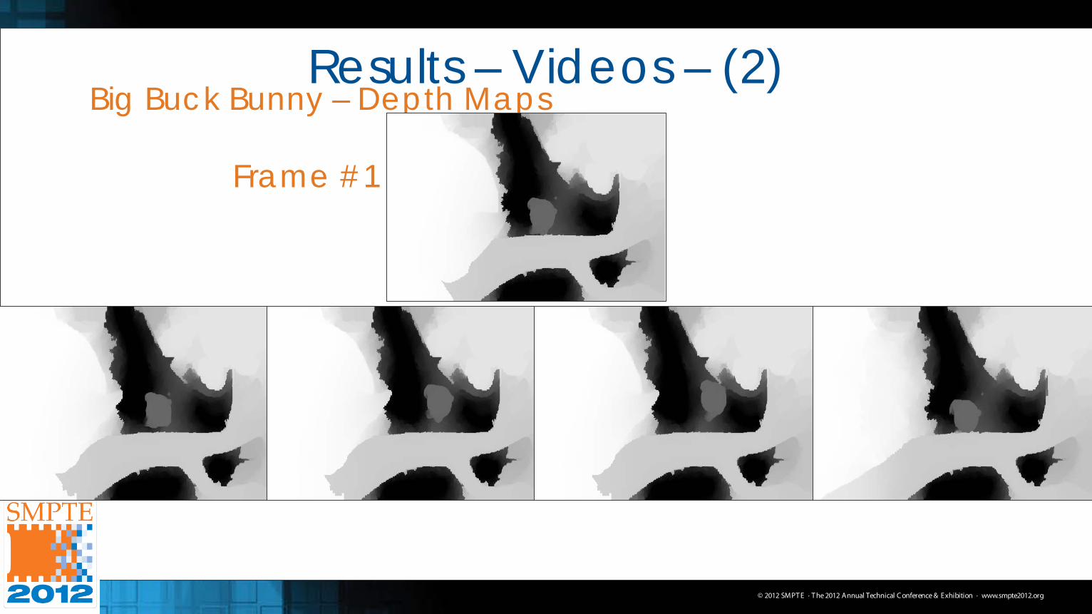
Results – Videos – (2) Big Buck Bunny – Depth Maps
Frame #1
© 2012 SMPT E · T he 2012 Annual Technical C onference & Exhibition · www.smpte2012.org
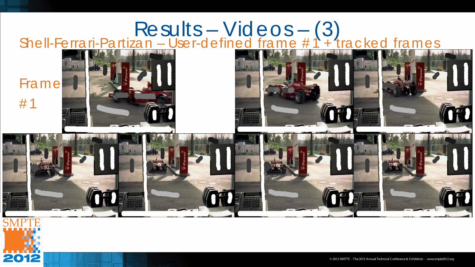
Results – Videos – (3) Shell-Ferrari-Partizan – User-defined frame #1 + tracked frames Frame #1
© 2012 SMPT E · T he 2012 Annual Technical C onference & Exhibition · www.smpte2012.org
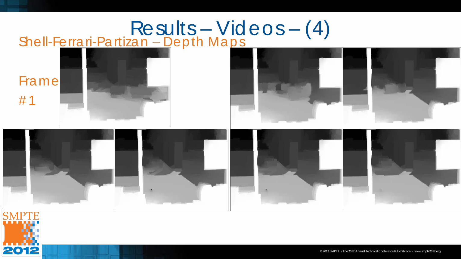
Results – Videos – (4) Shell-Ferrari-Partizan – Depth Maps Frame #1
© 2012 SMPT E · T he 2012 Annual Technical C onference & Exhibition · www.smpte2012.org
Conclusions • Made a semi-auto method for 2D-3D conversion
– Auto: Needs error correction & pre/post processing – Manual: Time-consuming and expensive – Happy medium between the two – Allows user to correct errors instantly and re-run fast
• Works for both images and video – Merged two segmentation algorithms together
• Combine merits of both methods together for better accuracy – Video: Modified a robust tracking algorithm to track
user-defined labels as well as dynamically adjust depths