unconstrained optimization 4 - ufl maeweb.mae.ufl.edu/nkim/eas6939/unconstrainedopt.pdf ·...
TRANSCRIPT

Section 4.1: Minimization of Functions of One Variable
Unconstrained Optimization 4
In this chapter we study mathematical programming techniques that are commonlyused to extremize nonlinear functions of single and multiple (n) design variablessubject to no constraints. Although most structural optimization problems involveconstraints that bound the design space, study of the methods of unconstrained op-timization is important for several reasons. First of all, if the design is at a stagewhere no constraints are active then the process of determining a search direction andtravel distance for minimizing the objective function involves an unconstrained func-tion minimization algorithm. Of course in such a case one has constantly to watchfor constraint violations during the move in design space. Secondly, a constrainedoptimization problem can be cast as an unconstrained minimization problem even ifthe constraints are active. The penalty function and multiplier methods discussed inChapter 5 are examples of such indirect methods that transform the constrained min-imization problem into an equivalent unconstrained problem. Finally, unconstrainedminimization strategies are becoming increasingly popular as techniques suitable forlinear and nonlinear structural analysis problems (see Kamat and Hayduk[1]) whichinvolve solution of a system of linear or nonlinear equations. The solution of suchsystems may be posed as finding the minimum of the potential energy of the systemor the minimum of the residuals of the equations in a least squared sense.
4.1 Minimization of Functions of One Variable
In most structural design problems the objective is to minimize a function withmany design variables, but the study of minimization of functions of a single de-sign variable is important for several reasons. First, some of the theoretical andnumerical aspects of minimization of functions of n variables can be best illustrated,especially graphically, in a one dimensional space. Secondly, most methods for un-constrained minimization of functions f(x) of n variables rely on sequential one-dimensional minimization of the function along a set of prescribed directions, sk, inthe multi-dimensional design space Rn. That is, for a given design point x0 and aspecified search direction at that point s0, all points located along that direction canbe expressed in terms of a single variable α by
x = x0 + αs0 , (4.1.1)
115

Chapter 4: Unconstrained Optimization
where α is usually referred to as the step length. The function f(x) to be minimizedcan, therefore, be expressed as
f(x) = f(x0 + αs0) = f(α) . (4.1.2)
Thus, the minimization problem reduces to finding the value α∗ that minimizes thefunction, f(α). In fact, one of the simplest methods used in minimizing functionsof n variables is to seek the minimum of the objective function by changing onlyone variable at a time, while keeping all other variables fixed, and performing a one-dimensional minimization along each of the coordinate directions of an n-dimensionaldesign space. This procedure is called the univariate search technique.
In classifying the minimization algorithms for both the one-dimensional andmulti-dimensional problems we generally use three distinct categories. These cat-egories are the zeroth, first, and second order methods. Zeroth order methods useonly the value of the function during the minimization process. First order methodsemploy values of the function and its first derivatives with respect to the variables.Finally, second order methods use the values of the function and its first and sec-ond derivatives. In the following discussion of one-variable function minimizations,the function is assumed to be in the form f = f(α). However, the methods to bediscussed are equally applicable for minimization of multivariable problems along apreselected direction, s, using Eq. (4.1.1).
4.1.1 Zeroth Order Methods
Bracketing Method. As the name suggests, this method brackets the minimum of thefunction to be minimized between two points, through a series of function evaluations.The method begins with an initial point α0, a function value f(α0), a step size β0,and a step expansion parameter γ > 1. The steps of the algorithm [2] are outlined as
1. Evaluate f(α0) and f(α0 + β0).
2. If f(α0 + β0) < f(α0), let α1 = α0 + β0 and β1 = γβ0, and evaluatef(α1 + β1). Otherwise go to step 4.
3. If f(α1 + β1) < f(α1), let α2 = α1 + β1 and β2 = γβ1, and continueincrementing the subscripts this way until f(αk + βk) > f(αk). Then, go to step 8.
4. Let α1 = α0 and β1 = −ξβ0, where ξ is a constant that satisfies 0 < ξ < 1/γ,and evaluate f(α1 + β1).
5. If f(α1 + β1) > f(α1) go to step 7.
6. Let α2 = α1 + β1 and β2 = γβ1, and continue incrementing the subscriptsthis way until f(αk + βk) > f(αk). Then, go to step 8.
7. The minimum has been bracketed between points (α0 − ξβ0) and (α0 + β0).Go to step 9.
8. The last three points satisfy the relations f(αk−2) > f(αk−1) and f(αk−1) <f(αk), and hence, the minimum is bracketed.
116

Section 4.1: Minimization of Functions of One Variable
9. Use either one of the two end points of the bracket as the initial point. Beginwith a reduced step size and repeat steps 1 through 8 to locate the minimum to adesired degree of accuracy.
Quadratic Interpolation. The method known as quadratic interpolation was firstproposed by Powell [3] and uses the values of the function f to be minimized at threepoints to fit a parabola
p(α) = a + bα + cα2 , (4.1.3)
through those points. The method starts with an initial point, say, α = 0 witha function value p0 = f(x0), and a step size β. Two more function evaluationsare performed as described in the following steps to determine the points for thepolynomial fit. In general, however, we start with a situation where we have alreadybracketed the minimum between α1 = αl and α2 = αu by using the bracketingmethod described earlier. In that case we will only need an intermediate point α0 inthe interval (αl, αu).
1. Evaluate p1 = p(β) = f(x0 + βs)
2. If p1 < p0, then evaluate p2 = p(2β) = f(x0 + 2βs). Otherwise evaluatep2 = p(−β) = f(x0−βs). The constants a, b, and c in equation Eq. (4.1.3) can nowbe uniquely expressed in terms of the function values p0, p1, and p2 as
a = p0 ,
b =4p1 − 3p0 − p2
2β, and c =
p2 + p0 − 2p1
2β2, if p2 = f(x0 + 2βs) , (4.1.4)
or
b =p1 − p2
2β, and c =
p1 − 2p0 + p2
2β2, if p2 = f(x0 − βs) . (4.1.5)
3. The value of α = α∗ at which p(α) is extremized for the current cycle is thengiven by
α∗ = − b
2c. (4.1.6)
4. α∗ corresponds to a minimum of p if c > 0, and the prediction based onEq. (4.1.3) is repeated using (x0 + α∗s) as the initial point for the next cycle withp0 = f(x0 + α∗s) until the desired accuracy is obtained.
5. If the point α = α∗ corresponds to a maximum of p rather than a minimum, orif it corresponds to a minimum of p which is at a distance greater than a prescribedmaximum βmax (possibly meaning α∗ is outside the bracket points), then the max-imum allowed step is taken in the direction of decreasing f and the point furthestaway from this new point is discarded in order to repeat the process.
In step 4, instead of starting with (x0 + α∗s) as the initial point and repeatingthe previous steps, there is a cheaper alternative in terms of the number of functionevaluations. The point (x0 + α∗s) and the two points closest to it from the left and
117

Chapter 4: Unconstrained Optimization
right can be used in another quadratic interpolation to give a better value of α∗.Other strategies for improving the accuracy of the prediction will be discussed laterin Section 4.1.4.
Fibonacci and the Golden Section Search. Like bracketing, the Fibonacci andthe golden section search techniques are very reliable, if not the most efficient, linesearch techniques for locating the unconstrained minimum of a function f(α) withinthe interval a0 ≤ α ≤ b0. It is assumed that the function f is unimodal, or that ithas only one minimum within the interval. Unimodal functions are not necessarilycontinuous or differentiable, nor convex (see Figure 4.1.1). A function is said to beunimodal [3] in the interval I0 if there exist an α∗ ∈ I0 such that α∗ minimizes f onI0, and for any two points α1, α2 ∈ I0 such that α1 < α2 we have
α2 ≤ α∗ implies that f(α1) > f(α2) , (4.1.7)
α1 ≥ α∗ implies that f(α2) > f(α1) . (4.1.8)
Figure 4.1.1 A typical unimodal function.
The assumption of unimodality is central to the Fibonacci search technique whichseeks to reduce the interval of uncertainty within which the minimum of the functionf lies.
The underlying idea behind the Fibonacci and the golden section search tech-niques can be explained as follows. Consider the minimization of f in the interval(a0, b0). Let us choose two points in the interval (a0, b0) at α = α1 and at α = α2
such that α1 < α2, and evaluate the function f at these two points. If f(α1) > f(α2),then since the function is unimodal the minimum cannot lie in the interval (a0, α1).The new interval is (α1, b0) which is smaller than the original interval. Similarly, iff(α2) > f(α1), then the new interval will be (a0, α2). The process can be repeated to
118

Section 4.1: Minimization of Functions of One Variable
reduce the interval to any desired level of accuracy. Only one function evaluation isrequired in each iteration after the first one, but we have not specified how to choosethe locations where f is evaluated. The best placement of these points will minimizethe number of function evaluations for a prescribed accuracy requirement (i.e., re-duction of the interval of uncertainty to a prescribed size). If the number of functionevaluations is n the most efficient process is provided by a symmetric placement ofthe points provided by the relations [4]
α1 = a0 +fn−1
fn+1
l0 , (4.1.9)
α2 = b0 −fn−1
fn+1
l0 , (4.1.10)
and
αk+1 = ak +fn−(k+1)
fn−(k−1)
lk = bk −fn−(k+1)
fn−(k−1)
lk , (4.1.11)
where fn are Fibonacci numbers defined by the sequence f0 = 1, f1 = 1, fn =fn−2 + fn−1, and lk is the length of the kth interval (ak, bk). The total number ofrequired function evaluations n may be determined from the desired level of accuracy.It can be shown that the interval of uncertainty after n function evaluations is 2εl0where
ε =1
fn+1
. (4.1.12)
A disadvantage of the technique is that the number of function evaluations hasto be specified in advance in order to start the Fibonacci search. To eliminate thisundesirable feature a quasi-optimal technique known as the golden section searchtechnique has been developed. The golden section search technique is based on thefinding that for sufficiently large n, the ratio
fn−1
fn+1
→ 0.382 . (4.1.13)
Thus, it is possible to approximate the optimal location of the points given by Eqs.(4.1.9 - 4.1.11) by the following relations
α1 = a0 + 0.382l0 , (4.1.14)
α2 = b0 − 0.382l0 , (4.1.15)
and
αk+1 = ak + 0.382lk = bk − 0.382lk . (4.1.16)
119

Chapter 4: Unconstrained Optimization
Example 4.1.1
Determine the value of α, to within ε = ±0.1, that minimizes the function f(α) =α(α− 3) on the interval 0 ≤ α ≤ 2 using the golden section search technique.
From Eqs. (4.1.14) and (4.1.15) we can calculate
α1 = 0 + 0.382(2) = 0.764, f(α1) = −1.708 ,
α2 = 2− 0.382(2) = 1.236, f(α2) = −2.180 .
Since f(α2) < f(α1) we retain (α1, 2). Thus, the next point is located at
α3 = 2− 0.382(2− 0.764) = 1.5278, f(α3) = −2.249 .
Since f(α3) < f(α2) we reject the interval (α1, α2). The new interval is (α2, 2). Thenext point is located at
α4 = 2− 0.382(2− 1.236) = 1.7082, f(α4) = −2.207 .
Since f(α4) < f(α2) < f(2) we reject the interval (α4, 2) and retain (α2, α4) as thenext interval and locate the point α5 at
α5 = 1.236 + 0.382(1.7082− 1.236) = 1.4164, f(α5) = −2.243 .
Since f(α5) < f(α4) < f(α2) we retain the interval (α5, α4). The next point is locatedat
α6 = 1.7082 + 0.382(1.7082− 1.4164) = 1.5967, f(α6) = −2.241 .
Figure 4.1.2 Iteration history for the function minimization f(α) = α(α− 3).
Since f(α6) < f(α4) we reject the interval (α6, α4) and retain the interval (α5, α6)of length 0.18, which is less than the interval of specified accuracy, 2ε = 0.2. Theiteration history for the problem is shown in Figure 4.1.2. Hence, the minimum hasbeen bracketed to within a resolution of ±0.1. That is, the minimum lies betweenα5 = 1.4164 and α6 = 1.5967. We can take the middle of the interval, α = 1.5066±0.0902 as the solution. The exact location of the minimum is at α = 1.5 where thefunction has the value −2.25. • • •
120

Section 4.1: Minimization of Functions of One Variable
4.1.2 First Order Methods
Bisection Method. Like the bracketing and the golden section search techniqueswhich progressively reduce the interval where the minimum is known to lie, thebisection technique locates the zero of the function f ′ by reducing the interval ofuncertainty. Beginning with the known interval (a, b) for which f ′(a)f ′(b) < 0, anapproximation to the root of f ′ is obtained from
α∗ =a + b
2, (4.1.17)
which is the point midway between a and b. The value of f ′ is then evaluated atα∗. If f ′(α∗) agrees in sign with f ′(a) then the point a is replaced by α∗ and the newinterval of uncertainty is given by (α∗, b). If on the other hand f ′(α∗) agrees in signwith f ′(b) then the point b is replaced by α∗ and the new interval of uncertainty is(a, α∗). The process is then repeated using Eq. (4.1.17).
Davidon’s Cubic Interpolation Method. This is a polynomial approximationmethod which uses both the function values and its derivatives for locating its min-imum. It is especially useful in those multivariable minimization techniques whichrequire the evaluation of the function and its gradients.
We begin by assuming the function to be minimized f(x0 + αs0) to be approxi-mated by a polynomial in the form
p(α) = a + bα + cα2 + dα3 , (4.1.18)
with constants a, b, c, and d to be determined from the values of the function,p0 and p1, and its derivatives, g0 and g1, at two points, one located at α = 0 andthe other at α = β.
p0 = p(0) = f(x0), p1 = p(β) = f(x0 + βs) , (4.1.19)
and
g0 =dp
dα(0) = sT∇f(x0), g1 =
dp
dα(β) = sT∇f(x0 + βs) . (4.1.20)
After substitutions, Eq. (4.1.18) takes the following form
p(α) = p0 + g0α−g0 + e
βα2 +
g0 + g1 + 2e
3β2α3 , (4.1.21)
where
e =3
β(p0 − p1) + g0 + g1 . (4.1.22)
We can now locate the minimum, α = αm, of Eq. (4.1.21) by setting its derivativewith respect to α to be zero. This results in
αm = β
(g0 + e± h
g0 + g1 + 2e
), (4.1.23)
121

Chapter 4: Unconstrained Optimization
whereh = (e2 − 2g0g1)
1/2 . (4.1.24)
It can be easily verified, by checking d2p/dα2, that the positive sign must be retainedin Eq. (4.1.23) for αm to be a minimum rather than a maximum. Thus, the algorithmfor Davidon’s cubic interpolation [5] may be summarized as follows.
1. Evaluate p0 = f(x0) and g0 = sT∇f(x0) and make sure that g0 < 0.
2. In the absence of an estimate of the initial step length β, we may calculate iton the basis of a quadratic interpolation derived using p0, g0 and an estimate of pmin.Thus,
β =2(pmin − p0)
g0
. (4.1.25)
3. Evaluate p1 = f(x0 + βs) and g1 =df(x0 + βs)
dβ
4. If g1 > 0 or if p1 > p0 go to step 6, or else go to step 5.
5. Replace β by 2β and go to step 3.
6. Calculate αm using Eq. (4.1.23) with a positive sign.
7. Use the interval (0, αm) if
gαm =df(x0 + αms)
dαm
≥ 0 , (4.1.26)
or else use the interval (αm, β) and return to step 4.
8. If αm corresponds to a maximum, restart the algorithm by using new points.Selection of the new points may be performed by using a strategy similar to thatdescribed for the quadratic interpolation technique.
4.1.3 Second Order Method
The problem of minimizing the function f(α) is equivalent to obtaining the root ofthe nonlinear equation
f ′(α) = 0 , (4.1.27)
because this is the necessary condition for the extremum of f . A convenient methodfor solving (4.1.27) is Newton’s method. This method consists of linearizing f ′(α)about a point α = αi and then determining the point αi+1 at which the linearapproximation
f ′(αi+1) = f ′(αi) + f ′′(αi)(αi+1 − αi) , (4.1.28)
vanishes. This point
αi+1 = αi −f ′(αi)
f ′′(αi), (4.1.29)
122

Section 4.2: Minimization of Functions of Several Variables
serves as a new approximation for a repeated application of Eq. (4.1.29) with i re-placed by i+1. For a successful convergence to the minimum it is necessary that thesecond derivative of the function f be greater than zero. Even so the method maydiverge depending on the starting point. Several strategies exist [6] which modifyNewton’s method to make it globally convergent (that is, it will converge to a mini-mum regardless of the starting point) for multivariable functions; some of these willbe covered in the next section.
The reason this method is known as a second order method is not only becauseit uses second derivative information about the function f , but also because it hasa rate of convergence to the minimum that is quadratic. In other words, Newton’salgorithm converges to the minimum α∗ such that
limi→∞
|αi+1 − α∗|(αi − α∗)2 = β , (4.1.30)
where αi and αi+1 are the ith and the (i + 1)st estimates of the minimum value ofthe α∗, β is a non-zero constant.
4.1.4 Safeguarded Polynomial Interpolation [7], p. 92
Polynomial interpolations such as the Quadratic interpolation and the Davidon’scubic interpolation are sometimes found to be quite inefficient and unreliable forlocating the minimum of a function along a line. If the interpolation function is notrepresentative of the behavior of the function to be minimized within the intervalof uncertainty, the minimum may fall outside the interval, or become unboundedbelow, or the successive iterations may be too close to one another without achievinga significant improvement in the function value. In such cases, we use what areknown as safeguarded procedures. These procedures consist of combining polynomialinterpolations with a simple bisection technique or the golden section search techniquedescribed earlier. At the end of the polynomial interpolation, the bisection techniquewould be used to find the zero of the derivative of the function f . The goldensection search, on the other hand, would work with the function f itself using theknown interval of uncertainty (a, b) and locate the point α∗ which corresponds to theminimum of f within the interval.
4.2 Minimization of Functions of Several Variables
4.2.1 Zeroth Order Methods
Several methods exist for minimizing a function of several variables using only func-tion values. However, only two of these methods may be regarded as being useful.These are the sequential simplex method of Spendley, Hext and Himsworth [8] and
123

Chapter 4: Unconstrained Optimization
Powell’s conjugate direction method [3]. Both of these methods require that thefunction f(x),x ∈ Rn, be unimodal; that is the function f has only one minimum.The sequential simplex does not require that the function f be differentiable, whilethe differentiability requirement on f is implicit in the exact line searches of Powell’smethod. It appears from tests by Nelder and Mead [9] that for most problems theperformance of the sequential simplex method is comparable to if not better thanPowell’s method. Both of these methods are considered inefficient for n ≥ 10; Pow-ell’s method may fail to converge for n ≥ 30. A more recent modification of thesimplex method by Chen, et al. [10] extends the applicability of this algorithm forhigh dimensional cases. If the function is differentiable, it is usually more efficientto use the more powerful first and second order methods with derivatives obtainedexplicitly or from finite difference formulae.
Sequential Simplex Method. The sequential simplex method was originally pro-posed by Spendley, Hext and Himsworth [8] and was subsequently improved by Nelderand Mead [9]. The method begins with a regular geometric figure called the simplexconsisting of n + 1 vertices in an n-dimensional space. These vertices may be definedby the origin and by points along each of the n coordinate directions. Such a simplexmay not be geometrically regular. The following equations are suggested in Ref. 8for the calculation of the positions of the vertices of a regular simplex of size a in then-dimensional design space
xj = x0 + pej +n∑
k=1k 6=j
qek, j = 1, . . . , n , (4.2.1)
with
p =a
n√
2(√
n + 1 + n− 1), and q =a
n√
2(√
n + 1− 1) , (4.2.2)
where ek is the unit base vector along the kth coordinate direction, and x0 is theinitial base point. For example, for a problem in two-dimensional design space Eqs.(4.2.1) and (4.2.2) lead to an equilateral triangle of side a.
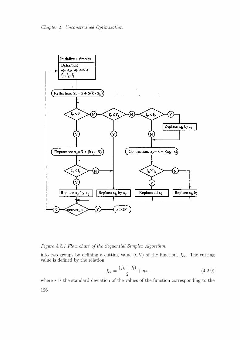
Once the simplex is defined, the function f is evaluated at each of the n+1 verticesx0,x1, . . . ,xn. Let xh and xl denote the vertices where the function f assumes itsmaximum and minimum values, respectively, and xs the vertex where it assumes thesecond highest value. The simplex method discards the vertex xh and replaces itby a point where f has a lower value. This is achieved by three operations namelyreflection, contraction, and expansion.
The reflection operation creates a new point xr along the line joining xh to thecentroid x̄ of the remaining points defined as
x̄ =1
n
n∑i=0
xi, i 6= h . (4.2.3)
The vertex at the end of the reflection is calculated by
xr = x̄ + α(x̄− xh) , (4.2.4)
124

Section 4.2: Minimization of Functions of Several Variables
with α being a positive constant called the reflection coefficient which is usuallyassumed to be unity. Any positive value of the reflection coefficient in Eq. (4.2.4)guarantees that xr is on the other side of the x̄ from xh. If the value of the functionat this new point, fr = f(xr), satisfies the condition fl < fr ≤ fs, then xh is replacedby xr and the process is repeated with this new simplex. If, on the other hand, thevalue of the function fr at the end of the reflection is less than the lowest value of thefunction fl = f(xl), then there is a possibility that we can still decrease the functionby going further along the same direction. We seek an improved point xe by theexpansion technique using the relation
xe = x̄ + β(xr − x̄) , (4.2.5)
with the expansion coefficient β often being chosen to be 2. If the value of the functionfe is smaller than the value at the end of the reflection step, then we replace xh byxe and repeat the process with the new simplex. However, if the expansion leads to afunction value equal to or larger than fr, then we form the new simplex by replacingxh by xr and continue.
Finally, if the process of reflection leads to a point xr such that, fr < fh, thenwe replace xh by xr and perform contraction. Otherwise (fr ≥ fh), we performcontraction without any replacement using
xc = x̄ + γ(xh − x̄) , (4.2.6)
with the contraction coefficient γ, 0 < γ < 1, usually chosen to be 1/2. If fc = f(xc)is greater than fh, then we replace all the points by a new set of points
xi = xi +1
2(xl − xi), i = 0, 1, . . . , n , (4.2.7)
and restart the process with this new simplex. Otherwise, we simply replace xh byxc and restart the process with this simplex. The operation in Eq. (4.2.7) causes thedistance between the points of the old simplex and the point with the lowest functionvalue to be halved and is therefore referred to as the shrinkage operation. The flowchart of the complete method is given in Figure 4.2.1. For the convergence criterionto terminate the algorithm Nelder and Mead [9] proposed the following{
1
1 + n
n∑i=0
[fi − f(x̄)]2
} 12
< ε , (4.2.8)
where ε is some specified accuracy requirement.
An improvement in the performance of the simplex algorithm for those cases withlarge number of design variables, n, is achieved by Chen, Saleem, and Grace [10]. Amodified simplex search procedure proposed in Ref. [10] executes the reflection,expansion, contraction, and, shrinkage operations on more than one vertex of thesimplex at a given step. This is achieved by first separating the vertices of the simplex
125
Chapter 4: Unconstrained Optimization
Figure 4.2.1 Flow chart of the Sequential Simplex Algorithm.
into two groups by defining a cutting value (CV) of the function, fcv. The cuttingvalue is defined by the relation
fcv =(fh + fl)
2+ ηs , (4.2.9)
where s is the standard deviation of the values of the function corresponding to the
126

Section 4.2: Minimization of Functions of Several Variables
vertices of the simplex,
s =
[n∑
i=0
(fi − f̄)2/(n + 1)
] 12
, (4.2.10)
and η is a parameter (discussed below) that controls the number of vertices to beoperated on. The f̄ value in Eq. (4.2.10) is the average of the function values overthe entire current simplex.
The vertices with function values higher than the cutting value form the groupto be reflected (and to be dropped). The other vertices serve as reference points.If the parameter η is sufficiently large, all the vertices of the simplex except the xh
stay in the group to be used as the reference points and, therefore, the algorithm isequivalent to the original form. For sufficiently small values of the parameter η, allpoints except the xn are dropped. The selection of the parameter η depends on thedifficulty of the problem as well as the number of variables. Recommended valuesfor η are given in Table II of Ref. [10]. Among the n + 1 vertices of the currentsimplex, we rearrange and number the vertices from largest to smallest functionvalues as x0,x1, . . . ,xcv, . . . ,xn where i = 0, . . . , ncv are the elements of the group tobe reflected next. The centroid of the vertices in the reference group is defined as
x̄ =1
n− ncv
n∑i=ncv+1
xi . (4.2.11)
The performance of this modified simplex method has been compared [10] with thesimplex method proposed by Nelder and Mead, and also with more powerful meth-ods such as the second order Davidon-Fletcher-Powell (DFP) method which will bediscussed later in this chapter. For high dimensional problems the modified simplexalgorithm was found to be more efficient and robust than the DFP algorithm. Nelderand Mead [9] have also provided several illustrations of the use of their algorithmin minimizing classical test functions and compared its performance with Powell’sconjugate directions method which will be discussed next.
Powell’s Conjugate Directions Method and its Subsequent Modification. Al-though most problems have functions which are not quadratic, many unconstrainedminimization algorithms are developed to minimize a quadratic function. This is be-cause a function can be approximated well by a quadratic function near a minimum.Powell’s conjugate directions algorithm is a typical example. A quadratic function inRn may be written as
f(x) =1
2xTQx + bTx + c . (4.2.12)
A set of directions si, i = 1, 2 . . . are said to be Q-conjugate if
sTi Qsj = 0, for i 6= j . (4.2.13)
Furthermore, it can be shown that if the function f is minimized once along eachdirection of a set s of linearly independent Q-conjugate directions then the minimum
127

Chapter 4: Unconstrained Optimization
of f will be located at or before the nth step regardless of the starting point providedthat no round-off errors are accumulated. This property is commonly referred to asthe quadratic termination property. Powell provided a convenient method for gen-erating such conjugate directions by a suitable combination of the simple univariatesearch and a pattern search technique [3]. However, in certain cases Powell’s algo-rithm generates directions which are linearly dependent and thereby fails to convergeto the minimum. Hence, Powell modified his algorithm to make it robust but at theexpense of its quadratic termination property.
Powell’s strategy for generating conjugate directions is based on the followingproperty (see Ref. 3 for proof). If x1 and x2 are any two points and s a specifieddirection, and x1s corresponds to the minimum point of a quadratic function f ona line starting at x1 along s and x2s is the minimum point on a line starting at x2
along s, then the directions s and (x2s − x1s) are Q-conjugate. The basic steps ofPowell’s modified method are based on a cycle of univariate minimizations. For eachcycle we use the following steps.
1. Minimize f along each of the coordinate directions (univariate search) startingat xk
0 and generating the points xk1, . . . ,x
kn where k is the cycle number.
2. After completing the univariate cycle find the index m corresponding to thedirection of the univariate search which yields the largest function decrease in goingfrom xk
m−1 to xkm.
3. Calculate the “pattern” direction skp = xk
n − xk0 (which is the sum of all the
univariate moves) and determine the value of α from xk0 along sk
p that minimizes f .
Denote this new point by xk+10 .
4. If
|α| <[
f(xk0)− f(xk+1
0 )
f(xkm−1)− f(xk
m)
] 12
, (4.2.14)
then use the same old directions again for the next univariate cycle (that is do notdiscard any of the directions of the previous cycle in preference to the pattern directionskp). If Eq. (4.2.14) is not satisfied then replace the mth direction by the pattern
direction skp.
5. Begin the next univariate cycle with the directions decided in step 4, andrepeat the steps 2 through 4 until convergence to a specified accuracy. Convergenceis assumed to be achieved when the Euclidean norm ‖xk−1 − xk‖ is less than a pre-specified quantity ε.
Although Powell’s original method does possess a quadratic termination property,his modified algorithm does not [3]. The modified method will now be illustrated onthe following simple example from structural analysis.
128

Section 4.2: Minimization of Functions of Several Variables
Example 4.2.1
The problem of determination of the maximum deflection and tip-rotation of a can-tilever beam of length l shown in Figure (4.2.2) loaded at its tip is considered. Solutionof this problem is formulated as a minimization of the total potential energy of thebeam which is modelled using a single cubic beam finite element. For a two-nodedbeam element with two degrees of freedom at each node, the displacement field isassumed to be
Figure 4.2.2 Tip loaded cantilever beam and its finite element model.
v(ξ) =[(1− 3ξ2 + 2ξ3) l(ξ − 2ξ2 + ξ3) (3ξ2 − 2ξ3) l(−ξ2 + ξ3)
]v1
θ1
v2
θ2
,
(4.2.15)where ξ = x/l. The corresponding potential energy of the beam model is given by
Π =EI
2l3
l∫0
(d2v
dξ2
)2
dξ + pv2 . (4.2.16)
Because of the cantilever end condition at ξ = 0, the first two degrees of freedomin Eq. (4.2.15) are zero. Therefore, substituting Eq. (4.2.15) into Eq. (4.2.16) weobtain
Π =EI
2l3(12v2
2 + 4θ22l
2 − 12v2θ2l) + pv2 . (4.2.17)
Defining f = 2Πl3/EI, x1 = v2, x2 = θ2l, and choosing pl3/EI = 1, the problemof determining the tip deflection and rotation of the beam reduces to an unconstrainedminimization of
f = 12x21 + 4x2
2 − 12x1x2 + 2x1 . (4.2.18)
Starting with an initial point of x10 = (−1, −2)T and f(x1
0) = 2 we will minimizef using Powell’s conjugate directions method. The exact solution of this problem isat x∗ = (−1/3, −1/2)T .
129

Chapter 4: Unconstrained Optimization
Since we have an explicit relation for the objective function f , the one dimensionalminimizations along a given direction will be performed exactly without resorting toany of the numerical techniques discussed in the previous section. However, if theseminimizations were done numerically, one of the zeroth order techniques would besufficient. We use superscripts to denote the univariate cycle number and subscriptsto denote the iteration number within a cycle.
First, we perform the univariate search along the x1 and x2 directions. Choosings11 = (1, 0)T we have
x11 =
{−1−2
}+ α
{10
}=
{−1 + α−2
}, (4.2.19)
and
f(α) = 12(−1 + α)2 + 4(−2)2 − 12(−1 + α)(−2) + 2(−1 + α) . (4.2.20)
Taking the derivative of Eq. (4.2.20) with respect to α, we obtain the value of αwhich minimizes f to be α = −1/12. Hence,
x11 =
{−1312−2
}and f(x1
1) = 1.916666667 .
Choosing s12 = (0, 1)T , we obtain
x12 =
{−1312−2
}+ α
{01
}=
{−1312
−2 + α
}, (4.2.21)
and
f(α) = 12
(−13
12
)2
+ 4(−2 + α)2 − 12
(−13
12
)(−2 + α) + 2
(−13
12
), (4.2.22)
which is minimum at α = 3/8. Therefore, at the end of the univariate search we have
x12 =
{ −1312
−138
}and f(x1
2) = 1.354166667 .
At this point we construct a pattern direction as
s1p = x1
2 − x10 =
{ −1312
−138
}−{−1−2
}=
{ −112
38
}, (4.2.23)
and minimize the function along this direction by
x20 =
{−1−2
}+ α
{ −112
38
}=
{−1− α12
−2 + 3α8
}, (4.2.24)
130

Section 4.2: Minimization of Functions of Several Variables
which attains its minimum value for α = 40/49 at
x20 =
{ −157147
−8349
}and f(x2
0) = 1.319727891 .
The direction that corresponds to the largest decrease in the objective function fduring the first cycle of the univariate search is associated with the second variable.We can now decide whether we want to replace the second (m = 2) univariate searchdirection by the pattern direction or not by checking the condition stated in step 4of the algorithm, Eq. (4.2.24). That is, Powell’s criterion
|α| = 40
49<
[2− 1.319727891
1.916666667− 1.354166667
] 12
. (4.2.25)
is satisfied, therefore, we retain the old univariate search directions for the secondcycle and restart the procedure by going back to step 2 of the algorithm. The resultsof the second cycle are tabulated in Table 4.2.1.
Table 4.2.1. Solution of the beam problem using Powell’s conjugate directions method
CycleNo. x1 x2 f
0 −1.0 −2.0 2.01 −1.083334 −2.0 1.9166671 −1.083334 −1.625 1.3541672 −0.895834 −1.625 0.93229672 −0.895834 −1.34375 0.61588542 −0.33334 −0.499999 −0.333333
The effectiveness of Powell’s modified method can be seen to be much morepronounced on the minimization of the following function considered by Avriel [2],
f = (x1 + x2 − x3)2 + (x1 − x2 + x3)
2 + (−x1 + x2 + x3)2 ,
and left as an exercise for the reader (see Exercise 2). • • •Before we proceed to the discussion of first order methods, it is worthwhile to
consider when zeroth order method should be used. The sequential simplex methodcan be used for non differentiable functions where first order methods are not appro-priate. For those unconstrained minimization problems with differentiable functions,it is preferable to calculate the exact derivatives, or generate such derivatives byusing finite differences and subsequently use a first order method for minimizationwhen these derivatives can be calculated accurately. Zeroth order methods such asPowell’s conjugate directions algorithm may still have a place for problems with ahighly nonlinear objective functions where the accuracy of the function evaluationsmay be poor. The poor accuracy in function evaluations may call for high orderfinite difference formulae to be used for derivative calculations, therefore, the use ofa zeroth order method for minimization may be a prudent alternative.
131

Chapter 4: Unconstrained Optimization
4.2.2 First Order Methods
First order methods for unconstrained minimization of a function f in Rn use thegradient of the function as well as its value in calculating the move direction forthe function minimization. These methods possess a linear or a superlinear rate ofconvergence. A sequence xk, k = 0, 1, 2, . . ., is said to be q-superlinear convergent tox∗ of order at least p if
‖xk+1 − x∗‖ ≤ ck‖xk − x∗‖p , (4.2.26)
where ck converges to zero. If ck in Eq.(4.2.26) is a constant then the convergence issaid to be a simple q-order convergence of order at least p. Thus, if p = 1 with ck
equal to a constant then we have a linear convergence rate, whereas if p = 1 and ck isa sequence that converges to zero then the convergence is said to be superlinear (seeRef. 6 for additional definitions).
Perhaps the oldest known method for minimizing a function of n variables is thesteepest descent method first proposed by Cauchy [11] for solving a system of linearequations. It can be used for function minimization as follows. The direction of moveis obtained by minimizing the directional derivative of f
∇fT s =n∑
i=1
∂f
∂xi
si , (4.2.27)
subject to the condition that s be a unit vector in Rn in the Euclidean sense.
sT s = 1 . (4.2.28)
It can easily be verified (see Exercise 6) that the steepest descent direction is givenby
s = − ∇f
‖∇f‖, (4.2.29)
where ‖ ‖ denotes the Euclidean norm, and it provides the largest decrease in thefunction f . Starting with a point xk at the kth iteration of the minimization process,we obtain the next point xk+1 as
xk+1 = xk + αs . (4.2.30)
Here s is given by Eq. (4.2.29) and α is determined such that f is minimized alongthe chosen direction by using any one of the one-dimensional minimization techniquescovered in the previous section. If the function to be minimized is quadratic in Rn
and expressed as
f =1
2xTQx + bTx + c , (4.2.31)
the step length can be determined directly by substituting Eq. (4.2.30) into Eq.(4.2.31) for the (k + 1)st iteration followed by a minimization of f with respect to αwhich yields
α∗ = −(xkTQ + bT )s
(sTQs). (4.2.32)
132

Section 4.2: Minimization of Functions of Several Variables
In obtaining Eq. (4.2.32) we assume that the Hessian matrix Q of the quadratic formis available explicitly, and we make use of the symmetry of Q.
The performance of the steepest descent method depends on the condition numberof the Hessian matrix Q. The condition number of a matrix is the ratio of the largestto the smallest eigenvalue. A large condition number implies that the contours ofthe function to be minimized form an elongated design space, and therefore theprogress made by the steepest descent method is very slow and proceeds in a zigzagpattern known as hemstitching. This is even true for quadratic functions, and canbe improved by re-scaling the variables.
Example 4.2.2
Figure 4.2.3 Contours of the cantilever beam potential energy function.
The cantilever problem discussed in the previous example illustrates this behaviormost vividly. The steepest descent method when applied to this problem may exhibitthe typical hemstitching phenomenon as shown in Figure 4.2.3 for certain initialstarting points. However, a simple transformation of variables to improve the scalingof the variables causes the steepest descent method to converge to the minimum in asingle step. For example, consider the following transformation
y1 = (x1 −1
2x2), y2 =
1√12
x2 . (4.2.33)
The function f may now be expressed in terms of the new variables y1 and y2 as
f(y1, y2) = y21 + y2
2 +1
6(y1 +
√3y2) . (4.2.34)
133

Chapter 4: Unconstrained Optimization
As a result of the scaling and elimination of the cross-product term, the conditionnumber of the Hessian of f is unity. Contours of the function f in the y1 − y2 planewill appear as circles. Beginning with any arbitrary starting point y0 and applyingthe steepest descent method we have
y1 = y0 + α
{2y10 + 1
6
2y20 +√
36
}. (4.2.35)
It can be easily verified that the value of α∗ that minimizes f is 0.5. Therefore,
y1 =
{ −112−√
312
},
at which the gradient of f is zero, implying that it is a minimum point. The corre-sponding values of the original variables x∗1, and x∗2 are −1/3 and −1/2, respectively.This simple demonstration clearly shows the effectiveness of scaling in convergenceof the steepest descent algorithm to the minimum of a function in Rn. It can beshown [6] that the steepest descent method has only a linear rate of convergence inthe absence of an appropriate scaling. • • •
Unfortunately, in most multivariable function minimizations it is not easy to de-termine the appropriate scaling transformation that leads to a one step convergenceto the minimum of a general quadratic form in Rn using the steepest descent algo-rithm. This would require calculating the Hessian matrix and then performing anexpensive eigenvalue analysis of the matrix. Hence, we are forced to look at otheralternatives for rapid convergence to the minimum of a quadratic form. One suchalternative is provided by minimizing along a set of conjugate gradient directionswhich guarantees a quadratic termination property. Hestenes and Stiefel [12] andlater Fletcher and Reeves [13] offered such an algorithm which will be covered next.
Fletcher-Reeves’ Conjugate Gradient Algorithm. This algorithm begins froman initial point x0 by first minimizing f along the steepest descent direction,s0 = −∇f(x0) = g0, to the new iterate x1. The direction for the next iterations1 must be constructed so that it is Q-conjugate to s0 where Q is the Hessian ofthe quadratic f . The function is then minimized along s1 to yield the next iteratex2. The next direction s2 from x2 is constructed to be Q-conjugate to the previousdirections s0 and s1, and the process is continued until convergence to the mini-mum is achieved. By virtue of Powell’s theorem on conjugate directions for quadraticfunctions, convergence to the minimum is theoretically guaranteed at the end of theminimization of the function f along the conjugate direction sn−1. For functionswhich are not quadratic, conjugacy of the directions si, i = 1, . . . , n loses its mean-ing since the Hessian of the functions is not a matrix of constants. However, it is acommon practice to use this algorithm for non-quadratic functions. Since, for suchfunctions, convergence to the minimum will rarely be achieved in n steps or less, thealgorithm is restarted after every n steps. The basic steps of the algorithm at the(k + 1)th iterate is as follows
1. Calculate xk+1 = xk + αk+1sk where αk+1 is determined such that
df(αk+1)
dαk+1
= 0 . (4.2.36)
134

Section 4.2: Minimization of Functions of Several Variables
2. Let sk = gk = −∇f(xk) if k = 0; and sk = gk + βksk−1 if k > 0 with
βk =gT
k gk
gTk−1gk−1
, and gk = −∇f(xk) . (4.2.37)
3. If ‖gk+1‖ or |f(xk+1)− f(xk)| is sufficiently small, then stop. Otherwise
4. If k < n go to step number 1, or else restart
Example 4.2.3
We will show the effectiveness of this method on the cantilever beam problem forwhich we minimize
f = 12x21 + 4x2
2 − 12x1x2 + 2x1 ,
starting with the initial design point xT0 = (−1,−2). The initial move direction is
calculated from the gradient
∇f(x0) =
{24x1 − 12x2 + 2
8x2 − 12x1
}x=x0
,
s0 = −∇f(x0) =
{−24
},
and at the end of the first step we have
x1 =
{−1−2
}+ α1
{−24
},
f(α1) = 12(−1− 2α1)2 + 4(−1 + 4α1)
2 − 12(−1− 2α1)(−2 + 4α1) + 2(−1− 2α1) .
The value of α1 for which the function f is a minimum is obtained from the conditiondf/dα1 = 0, or α1 = 0.048077. The new design point and the gradient at that pointare
x1 =
{−1.0961−1.8077
}, and ∇f(x1) =
{−2.6154−1.3077
}.
Next, let s1 = −∇f(x1) + β1s0 with β1 from Eq. (4.2.37), or
β1 =(−2.6154)2 + (−1.3077)2
(−2)2 + (4)2= 0.4275 ,
The new move direction is
s1 = −{−2.6154−1.3077
}+ 0.4275
{−24
}=
{1.760363.0178
},
and
x2 =
{−1.0961−1.8077
}+ α2
{1.760363.0178
}.
135

Chapter 4: Unconstrained Optimization
Again setting df(α2)/d(α2) = 0 we obtain α2 = 0.4334,
x2 =
{−0.3334−0.50
}, and ∇f(x2) =
{00
}.
Finally, since {−24
}T [24 −12−12 8
]{1.760363.0178
}' 0 .
we have verified the Q-conjugacy of the two directions s0 and s1. The progress ofminimization using this method is illustrated in Figure (4.2.3). • • •
Beale’s Restarted Conjugate Gradient Technique. In minimizing non-quadraticfunctions using the conjugate gradient method, restarting the method after everyn steps is not always a good strategy. Such a strategy seems to be insensitive tothe nonlinear character of the function being minimized. Beale [14] and later Powell[15] have proposed restart techniques that take the nonlinearity of the function intoaccount in deciding when to restart the algorithm. Numerical experiments withminimization of several general functions have led to the following algorithm by Powell[15].
1. Given x0, define s0 to be the steepest descent direction,
s0 = −∇f(x0) = g0 ,
let k = t = 0, and begin iterations by incrementing k.
2. For k ≥ 1 the direction sk is defined by Beale’s formula [14]
sk = −gk + βksk−1 + γkst, and gk = −∇f(xk) , (4.2.38)
where
βk =gT
k [gk − gk−1]
sTk−1[gk − gk−1]
, (4.2.39)
and
γk =gT
k [gt+1 − gt]
sTt [gt+1 − gt]
, if k > t + 1 , (4.2.40)
γk = 0, if k = t + 1 . (4.2.41)
3. For k ≥ 1 test the inequality
|gTk−1gk| ≥ 0.2‖gk‖2 . (4.2.42)
If this inequality holds, then it is taken to be an indication that enough orthogonalitybetween gk−1and gk has been lost to warrant a restart. Accordingly, t is resett = k − 1 to imply restart.
4. For k > t + 1 the direction sk is also checked to guarantee a sufficiently largegradient by testing the inequalities
−1.2‖gk‖2 ≤ sTk gk ≤ −0.8‖gk‖2 . (4.2.43)
136

Section 4.2: Minimization of Functions of Several Variables
If these inequalities are not satisfied, the algorithm is restarted by setting t = k − 1.
5. Finally, the algorithm is also restarted by setting t = k − 1, if k − t ≥ n as inthe case of the Fletcher-Reeves method.
6. The process is terminated if ‖gk−1‖ or |f(xk+1) − f(xk)| is sufficiently small.If not, k is incremented by one and the process is repeated by going to step 2.
Powell [15] has examined in great detail the effectiveness of the new restart proce-dure using Beale’s basic algorithm on a variety of problems. These experiments clearlyestablish the superiority of the new procedure over the algorithms of Fletcher-Reevesand Polak-Ribiere [16]. The only disadvantage of this new algorithm appears to be itsslightly increased storage requirements arising from the need for storing the vectorsst and (gt+1 − gt) after a restart. More recent enhancement for the first order con-jugate gradient type algorithms [17, 18] involve inclusion of certain preconditioningschemes to improve the rate of convergence.
4.2.3 Second Order Methods
The oldest second order method for minimizing a nonlinear multivariable functionin Rn is Newton’s method. The motivation behind Newton’s method is identicalto the steepest descent method. In arriving at the steepest descent direction, s, weminimized the directional derivative, Eq. (4.2.27), subject to the condition that theEuclidean norm of s was unity, Eq. (4.2.28). The Euclidean norm, however, does notconsider the curvature of the surface. Hence, it motivates the definition of a differentnorm or a metric of the surface. Thus, we pose the problem as finding the directions that minimizes
∇fT s =n∑
i=1
∂f
∂xi
si , (4.2.44)
subject to the condition thatsTQs = 1 . (4.2.45)
The solution of this problem is provided by Newton direction (see Exercise 6) towithin a multiplicative constant, namely
s = −Q−1∇f , (4.2.46)
where Q is the Hessian of the objective function. The general form of the updateequation of Newton’s method for minimizing a function in Rn is given by
xk+1 = xk − αk+1Q−1k ∇f(xk) , (4.2.47)
where αk+1 is determined by minimizing f along the Newton direction. For Q = I,Eq. (4.2.47) yields the steepest descent solution since the norm in Eq. (4.2.45)reduces to the Euclidean norm. For quadratic functions it can be shown that theupdate equation reaches the optimum solution in one step with α = 1
x∗ = x0 − [Q(x0)]−1[∇f(x0)] , (4.2.48)
137

Chapter 4: Unconstrained Optimization
regardless of the initial point x0.
Newton’s method can also shown to have a quadratic rate of convergence (seefor example [4] or [8]), but the serious disadvantages of the method are the need toevaluate the Hessian Q and then solve the system of equations
Qs = −∇f , (4.2.49)
to obtain the direction vector s. For every iteration (if Q is non-sparse), Newton’smethod involves the calculation of n(n + 1)/2 elements of the symmetric Q matrix,and n3 operations for obtaining s from the solution of Eqs. (4.2.49). It is this featureof Newton’s method that has led to the development of methods known as quasi-Newton or variable-metric methods which seek to use the gradient information toconstruct approximations for the Hessian matrix or its inverse.
Quasi-Newton or Variable Metric Algorithms . Consider the Taylor series expan-sion of the gradient of f around xk+1
∇f(xk+1) ' ∇f(xk) + Q(xk+1 − xk) , (4.2.50)
where Q is the actual Hessian of the function f . Assuming Ak(Ak ≡ A(xk)) to bean approximation to the Hessian at the kth iteration, we may write equation (4.2.50)in a more compact form as
yk = Akpk , (4.2.51)
where
yk = ∇f(xk+1)−∇f(xk), and pk = xk+1 − xk , (4.2.52)
Similarly, the solution of Eq. (4.2.51) for pk can be written as
Bk+1yk = pk , (4.2.53)
with Bk+1 being an approximate inverse of the Hessian Q. If Bk+1 is to behaveeventually as Q−1 then Bk+1Ak = I. Equation (4.2.53) is known as the quasi-Newtonor the secant relation. The basis for all variable-metric or quasi-Newton methods isthat, the formulae which update the matrix Ak or its inverse Bk must satisfy Eq.(4.2.53) and, in addition, maintain the symmetry and positive definiteness properties.In other words, if Ak or Bk are positive definite then Ak+1 or Bk+1 must remain so.
A typical variable-metric algorithm with an inverse Hessian update may be statedas
xk+1 = xk − αk+1sk , (4.2.54)
wheresk = −Bk∇f(xk) , (4.2.55)
with Bk being a positive definite symmetric matrix.
Rank-One Updates. In the class of rank-one updates we have the well-knownsymmetric Broyden’s update [19] for Bk+1 given as
Bk+1 = Bk +(pk −Bkyk)(pk −Bkyk)
T
(pk −Bkyk)Tyk
. (4.2.56)
138

Section 4.2: Minimization of Functions of Several Variables
To start the algorithm, an initial positive definite symmetric matrix B0 is assumedand the next point x1 is calculated from Eq. (4.2.54). Then, Eq. (4.2.56) is usedto calculate the updated approximate inverse Hessian matrix. It is easy to verifythat the columns of the second matrix on the right-hand side of Eq. (4.2.56) aremultiples of each other. In other words, the update matrix has a single independentcolumn and, hence is rank-one. Furthermore, if Bk is symmetric then Bk+1 will alsobe symmetric. It is, however, not guaranteed that Bk+1 will remain positive definiteeven if Bk is. This fact can lead to a breakdown of the algorithm especially whenapplied to general non-quadratic functions. Broyden [19] suggests choosing the steplengths αk+1 in Eq. (4.2.54) by either (i) an exact line search, or by (ii) αk+1 = 1 forall steps, or by (iii) choosing αk+1 such that ‖∇f‖ is minimized or reduced.
Irrespective of the type of line search used, Broyden’s update guarantees aquadratic termination property. However, because of the lack of robustness in min-imizing general non-quadratic functions, rank-one updates have been superseded byrank-two updates which guarantee both symmetry and positive definiteness of theupdated matrices.
Rank-Two Updates. Rank-two updates for the inverse Hessian approximationmay generally be written as
Bk+1 =
[Bk −
BkykyTk Bk
yTk Bkyk
+ θkvkvTk
]ρk +
pkpTk
pTk yk
, (4.2.57)
where
vk = (yTk Bkyk)
12
[pk
pTk yk
− Bkyk
yTk Bkyk
], (4.2.58)
and θk and ρk are scalar parameters that are chosen appropriately. Updates givenby Eqs. (4.2.57) and (4.2.58) are subsets of Huang’s family of updates [20] whichguarantee that Bk+1yk = pk for all choices of θk and ρk. If we set θk = 0 andρk = 1 for all k we obtain the Davidon-Fletcher-Powell’s (DFP) update formula [21,22] which is given as
Bk+1 = Bk −Bkyky
Tk Bk
yTk Bkyk
+pkp
Tk
pTk yk
. (4.2.59)
The DFP update formula preserves the positive definiteness and symmetry of thematrices Bk, and has some other interesting properties as well. When used for mini-mizing quadratic functions, it generates Q-conjugate directions and, therefore, at thenth iteration Bn becomes the exact inverse of the Hessian Q. Thus, it has the featuresof the conjugate gradient as well as the Newton-type algorithms. The DFP algorithmcan be used without an exact line search in determining αk+1 in Eq. (4.2.54). How-ever, the step length must guarantee a reduction in the function value, and mustbe such that pT
k yk > 0 in order to maintain positive definiteness of Bk. The perfor-mance of the algorithm, however, was shown to deteriorate as the accuracy of the linesearch decreases [20]. In most cases the DFP formula works quite successfully. In afew cases the algorithm has been known to break down because Bk became singular.This has led to the introduction of another update formula developed simultaneously
139

Chapter 4: Unconstrained Optimization
by Broyden [19], Fletcher [23], Goldfarb [24], and Shanno [25] and known known asBFGS formula. This formula can be obtained by putting θk = 1 and ρk = 1 in Eq.(4.2.57) which reduces to
Bk+1 = Bk +
[1 +
yTk Bkyk
pTk yk
]pkp
Tk
pTk yk
− pkyTk Bk
pTk yk
− BkykpTk
pTk yk
. (4.2.60)
Equation (4.2.60) can also be written in a more compact manner as
Bk+1 =
[I− pky
Tk
pTk yk
]Bk
[I− ykp
Tk
pTk yk
]+
pkpTk
pTk yk
. (4.2.61)
Using Ak+1 = B−1k+1 and Ak = B−1
k we can invert the above formula to arrive at anupdate for the Hessian approximations. It is found that this update formula reducesto
Ak+1 = Ak −Akpkp
Tk Ak
pTk Akpk
+yky
Tk
yTk pk
, (4.2.62)
which is the analog of the DFP formula (4.2.59) with Bk replaced by Ak, andpk and yk interchanged. Conversely, if the inverse Hessian Bk is updated by the DFPformula then the Hessian Ak is updated according to an analog of the DFP formula.It is for this reason that the BFGS formula is often called the complementary DFPformula. Numerical experiments with BFGS algorithm [26] suggest that it is superiorto all known variable-metric algorithms. We will illustrate its use by minimizing thepotential energy function of the cantilever beam problem.
Example 4.2.4
Minimize f(x1, x2) = 12x21 +4x2
2−12x1x2 +2x1 by using the BFGS update algorithmwith exact line searches starting with the initial guess xT
0 = (−1,−2).
We initiate the algorithm with a line search along the steepest descent direction.This is associated with the assumption that B0 = I which is symmetric and positivedefinite. The resulting point is previously calculated in example 4.2.3 to be
x1 =
{−1.0961−1.8077
}, and ∇f(x1) =
{−2.6154−1.3077
}.
From Eq. (4.2.52) we calculate
p0 =
{−1.0961−1.8077
}−{−1−2
}=
{−0.09610.1923
},
y0 =
{−2.6154−1.3077
}−{
2−4
}=
{−4.61542.6923
}.
Substituting the terms
pT0 y0 = (−0.0961)(−4.6154) + (0.1923)(2.6923) = 0.96127 ,
140

Section 4.2: Minimization of Functions of Several Variables
p0yT0 =
{−0.09610.1923
}[−4.6154 2.6923]
=
[0.44354 −0.25873−0.88754 0.51773
],
into Eq. (4.2.61), we obtain
B1 =
([1 00 1
]− 1
0.96127
[0.44354 −0.25873−0.88754 0.51773
])[1 00 1
]
×([
1 00 1
]− 1
0.96127
[0.44354 −0.88754−0.25873 0.51773
])+
1
0.96127
[0.00923 −0.01848−0.01848 0.03698
],
=
[0.37213 0.602250.60225 1.10385
].
Next, we calculate the new move direction from Eq. (4.2.55)
s1 = −[
0.37213 0.602250.60225 1.10385
]{−2.6154−1.3077
}=
{1.76083.0186
},
and obtain
x2 =
{−1.0961−1.8077
}+ α2
{1.76083.0186
}.
Setting the derivative of f(x2) with respect to α2 to 0 yields the value α2 = 0.4332055,and
x2 =
{−0.3333−0.5000
}, with ∇f(x2) '
{00
}.
This implies convergence to the exact solution. It is left to the reader to verify thatif B1 is updated once more we obtain
B2 =
[0.1667 0.250.25 0.5
],
which is the exact inverse of the Hessian matrix
Q =
[24 −12−12 8
].
It can also be verified that, as expected, the directions s0 and s1 are Q-conjugate.• • •
Q-conjugacy of the directions of travel has meaning only for quadratic functions,and is guaranteed for such problems in the case of variable-metric algorithms be-longing to Huang’s family only if the line searches are exact. In fact, Q-conjugacyof the directions is not necessary for ensuring a quadratic termination property [26].This realization has led to the development of methods based on the DFP and BFGSformulae that abandon the computationally expensive exact line searches. The linesearches must be such that they guarantee positive definiteness of the Ak or Bk
matrices while reducing the function value appropriately. Positive definiteness is
141
Chapter 4: Unconstrained Optimization
guaranteed as long as pTk yk > 0. To ensure a wide radius of convergence for a quasi-
Newton method, it is also necessary to satisfy the following two criteria. First, asufficiently large decrease in the function f must be achieved for the step taken and,second, the rate of decrease of f in the direction sk at xk+1 must be smaller than therate of decrease of f at xk [26]. In view of this observations, most algorithms withinexact line searches require the satisfaction of the following two conditions.
f(xk+1) < f(xk) + 10−4αsT∇f(xk) , (4.2.63)
and ∣∣∣∣sT∇f(xk+1)
sT∇f(xk)
∣∣∣∣ < 0.9 . (4.2.64)
The convergence of the BFGS algorithm under these conditions has been studied byPowell [27]. Similar convergence studies with Beale’s restarted conjugate gradientmethod under the same two conditions have been carried out by Shanno [28].
4.2.4 Applications to Analysis
Several of the algorithms for unconstrained minimization of functions in Rn can alsobe used for solving a system of linear or nonlinear equations. In some cases, like theproblems of nonlinear structural analysis, the necessary condition for the potentialenergy to be stationary is that its gradient vanish. The latter can be construed assolving a system of equations of the type
∇f(x) = g(x) = 0 , (4.2.65)
where the Hessian of f and the Jacobian of g are the same. In cases where theproblems are posed directly as
g(x) = 0 , (4.2.66)
Dennis and Schnabel [6] and others solve Eq. (4.4.2) by minimizing the nonlinearleast squares function
f =1
2gTg . (4.2.67)
In this case, however, the Hessian of f and the Jacobian of g are not identical but apositive definite approximation to the Hessian of f appropriate for most minimiza-tion schemes can be easily generated from the Jacobian of g [6]. Minimization of fthen permits the determination of not only stable but also unstable equilibrium con-figurations provided the minimization does not converge to a local minimum. In thecase of convergence to a local minimum, certain restart [6] or deflation and tunnellingtechniques [29, 30] can be invoked to force convergence to the global minimum of fat which ‖g‖ = 0.
142

Section 4.3: Specialized Quasi-Newton Methods
4.3 Specialized Quasi-Newton Methods
4.3.1 Exploiting Sparsity
The rank-one and rank-two updates that we discussed in the previous section yieldupdates which are symmetric but not necessarily sparse. In other words the Hessianor Hessian inverse updates lead to symmetric matrices which are fully populated. Inmost structural analysis problems using the finite element method it is well knownthat the Hessian of the potential energy (the tangent stiffness matrix) is sparse. Thismay be also true of many structural optimization problems. For such sparse systemsthe solution phase for finite element models exploits the triple LDLT factorization.Thus the Hessian or the Hessian inverse updates discussed previously are not ap-propriate for solving large-scale structural analysis problems which involve sparseHessians.
In applying the BFGS method for solving large-scale nonlinear problems of struc-tural analysis Matthies and Strang [31] have proposed an alternate implementationof the method suitable for handling large sparse problems by storing the vectors
pk = xk+1 − xk , (4.3.1)
andyk = ∇f(xk+1)−∇f(xk) , (4.3.2)
and reintroducing them to compute the new search directions. After a sequence offive to ten iterations during which the BFGS updates are used, the stiffness matrixis recomputed and the update information is deleted.
Sparse updates for solving large-scale problems were perhaps first proposed bySchubert [32], who proposed a modification of Broyden’s method [33] according towhich the ith row of the Hessian Ak+1 is updated by using
A(i)k+1 = A
(i)k +
[gi(xk+1)− (1− αk)g(xk)]
αkp̂Tk p̂k
, (4.3.3)
with p̂k obtained from pk by setting to zero those components corresponding to
known zeros in A(i)k . The method has the drawback, however, that it cannot retain
symmetry of the resulting matrix even when starting with a symmetric, positivedefinite matrix. Not only does this result in slightly increased demands on storage,but it also requires special sparse linear equation solvers. Toint [34] and Shanno[35] have recently proposed algorithms which find updating formulae for symmetricHessian matrices that preserve known sparsity conditions. The update is obtainedby calculating the smallest correction subject to linear constraints that include thesparsity conditions. This involves the solution of a system of equations with the samesparsity pattern as the Hessian.
143

Chapter 4: Unconstrained Optimization
Curtis, Powell and Reid [36], and Powell and Toint [37] have proposed finitedifference strategies for the direct evaluation of sparse Hessians of functions. Inaddition to using the finite difference operations, they used concepts from graphtheory that minimize the number of gradient evaluations required for computing thefew non-zero entries of a sparse Hessian. By using these strategies, we can exploitthe sparsity not only in the computation of the Newton direction but also in theformation of Hessians [38, 39]
The Curtis-Powell-Reid (CPR) strategy exploits sparsity, but not the symmetryof the Hessian. It divides the columns of the Hessian into groups, so that in eachgroup the row numbers of the unknown elements of the column vectors are all dif-ferent. After the formation of the first group, other groups are formed successivelyby applying the same strategy to columns not included in the previous groups. Thenumber of such groups for sparse or banded matrices is usually very small by compar-ison with n. To evaluate the Hessian of f at x0 we evaluate the gradient of f at x0.After this initial gradient evaluation, only as many more gradient evaluations as thenumber of groups are needed to evaluate all the non-zero elements of the Hessianusing forward difference approximation. Thus
aij =∂gi
∂xj
=gi(x0 + hjej)− gi(x0)
hj
, (4.3.4)
where ej is the jth coordinate vector and hj is a suitable step size. Each step size maybe adjusted such that the greatest ratio of the round-off to truncation error for anycolumn of the Hessian falls within a specified range. However, such an adjustment ofstep sizes would require a significantly large number of gradient evaluations. Hence,to economize on the number of gradient evaluations the step sizes are not allowed toleave the range
[max(ε|xj|, ηhuj), huj] , (4.3.5)
where ε is the greatest relative round-off in a single operation, η is the relative machineprecision, and huj is an upper bound on hj [36].
Powell and Toint [37] extended the CPR strategy to exploit symmetry of theHessian. They proposed two methods, one of which is known as the substitutionmethod. According to this, the CPR strategy is first applied to the lower triangularpart, L, of the symmetric Hessian, A. Because, all the elements of A computed thisway will not be correct, the incorrect elements are corrected by a back-substitutionscheme. Details of this back-substitution scheme may be found in Ref. 37.
The Powell-Toint (PT) strategy of estimating sparse Hessians directly appearsto be a much better alternative to Toint’s sparse update algorithm [38]. One majordrawback of Toint’s update algorithm is that the updated Hessian approximation isnot guaranteed to remain positive definite even if the initial Hessian approximationwas positive definite.
4.3.2 Coercion of Hessians for Suitability with Quasi-Newton Methods
In minimizing a multivariable function f using a discrete Newton method or theToint’s update algorithm we must ensure that the Hessian approximation is positive
144

Section 4.4: Probabilistic Search Algorithms
definite. If this is not so, then Newton’s direction is not guaranteed to be a descentdirection. There are several strategies for coercing an indefinite Hessian to a positivedefinite form. Prominent among these strategies is the one proposed by Gill andMurray [40]. The most impressive feature of this strategy is that the coercion ofthe Hessian takes place during its LDLT decomposition for the computation of theNewton direction. The diagonal elements of the D matrix are forced to be sufficientlypositive to avoid numerical difficulties while the off-diagonal terms of LD1/2 are lim-ited by a quantity designed to guarantee positive definiteness of the resulting matrix.This is equivalent to modifying the original non-positive definite Hessian matrix bythe addition of an appropriate diagonal matrix. Because this matrix modificationis carried out during its LDLT decomposition, the strategy for the computation ofNewton’s descent direction does not entail a great deal of additional computations.
4.3.3 Making Quasi-Newton Methods Globally Convergent
It is well known that despite a positive definite Hessian approximation, New-ton’s method can diverge for some starting points. Standard backtracking alongthe Newton direction by choosing shorter step lengths can achieve convergence tothe minimum. However, backtracking along the Newton direction fails to use then-dimensional quadratic model of the function f . Dennis and Schnabel [7] have pro-posed a strategy called the double-dogleg strategy which uses the full n-dimensionalquadratic model to choose a new direction obtained by a linear combination of thesteepest descent and the Newton direction. This new direction is a function of theradius of the trust region within which the n-dimensional quadratic model of thefunction approximates the true function well. The double-dogleg strategy not onlymakes Newton’s method globally convergent (that is converge to the minimum of thefunction irrespective of the starting point) but also makes it significantly more effi-cient for certain poorly scaled problems. For details about the double-dogleg strategyreaders are advised to consult Ref. 7. More recent attempts to widen the domain ofconvergence of the quasi-Newton method or make it globally convergent for a wideclass of problems are studied in Refs. [41, 42].
4.4 Probabilistic Search Algorithms
A common disadvantage of most of the algorithms discussed so far is their inabilityto distinguish local and global minima. Many structural design problems have morethan one local minimum, and depending on the starting point, these algorithmsmay converge to one of these local minima. The simplest way to check for a betterlocal solution is to restart the optimization from randomly selected initial points tocheck if other solutions are possible. However, for problems with a large number ofvariables the possibility of missing the global minimum is large unless unpracticallylarge number of optimization runs are performed. The topic of global optimizationis an area of active research where new algorithms are emerging and old algorithmsare constantly being improved [43–45].
145

Chapter 4: Unconstrained Optimization
Dealing with the problem of local minima becomes even worse if the design vari-ables are required to take discrete values. First of all, for such problems the designspace is discontinuous and disjointed, therefore derivative information is either uselessor is not defined. Secondly, the use of discrete values for the design variables intro-duces multiple minima corresponding to various combinations of the variables, even ifthe objective function for the problem has a single minimum for continuous variables.A methodical way of dealing with multiple minima for discrete optimization prob-lems is to use either random search techniques that would sample the design spacefor a global minimum or to employ enumerative type algorithms. In either case, theefficiency of the solution process deteriorates dramatically as the number of variablesis increased.
Two algorithms, Simulated Annealing and Genetic Algorithms (see, Laarhoven[46] and Goldberg [47], respectively), have emerged more recently as tools ideallysuited for optimization problems where a global minimum is sought. In addition tobeing able to locate near global solutions, these two algorithms are also powerful toolsfor problems with discrete-valued design variables. Both algorithms rely on naturallyobserved phenomena and their implementation calls for the use of a random selectionprocess which is guided by probabilistic decisions. In the following sections briefdescriptions of the two algorithms are presented. Application of the algorithms tostructural design will be demonstrated for laminated composites in Chapter 11.
4.4.1 Simulated Annealing
The development of the simulated annealing algorithm was motivated by studies instatistical mechanics which deal with the equilibrium of large number of atoms insolids and liquids at a given temperature. During solidification of metals or forma-tion of crystals, for example, a number of solid states with different internal atomicor crystalline structure that correspond to different energy levels can be achieveddepending on the rate of cooling. If the system is cooled too rapidly, it is likely thatthe resulting solid state would have a small margin of stability because the atoms willassume relative positions in the lattice structure to reach an energy state which isonly locally minimal. In order to reach a more stable, globally minimum energy state,the process of annealing is used in which the metal is reheated to a high temperatureand cooled slowly, allowing the atoms enough time to find positions that minimizea steady state potential energy. It is observed in the natural annealing process thatduring the time spent at a given temperature it is possible to have the system jumpto a higher energy state temporarily before the steady state is reached. As will beexplained in the following paragraphs, it is this characteristic of the annealing processwhich makes it possible to achieve near global minimum energy states.
A computational algorithm that simulates the annealing process was proposedby Metropolis et al. [48], and is referred to as the Metropolis algorithm. At a giventemperature, T , the algorithm perturbs the position of an atom randomly and com-putes the resulting change in the energy of the system, ∆E. If the new energy stateis lower than the initial state, then the new configuration of the atoms is accepted.If, on the other hand ∆E ≥ 0, the perturbed state causes an increase in the energy,
146

Section 4.4: Probabilistic Search Algorithms
the new state might be accepted or rejected based on a random probabilistic decision.The probability of acceptance, P(∆E), of a higher energy state is computed as
P(∆E) = e
(−∆EkBT
), (4.4.1)
where kB is the Boltzmann’s constant. If the temperature of the system is high, thenthe probability of acceptance of a higher energy state is close to one. If, on the otherhand, the temperature is close to zero, then the probability of acceptance becomesvery small.
The decision to accept or reject is made by randomly selecting a number in aninterval (0, 1) and comparing it with P(∆E). If the number is less than P(∆E), thenthe perturbed state is accepted, if it is greater than P(∆E), the state is rejected.At each temperature, a pool of atomic structures would be generated by randomlyperturbing positions until a steady state energy level is reached (commonly referredto as thermal equilibrium). Then the temperature is reduced to start the iterationsagain. These steps are repeated iteratively while reducing the temperature slowly toachieve the minimal energy state.
The analogy between the simulated annealing and the optimization of functionswith many variables was established recently by Kirkpatrick et al. [49], and Cerny[50]. By replacing the energy state with an objective function f , and using variablesx for the the configurations of the particles, we can apply the Metropolis algorithmto optimization problems. The method requires only function values. The moves inthe design space from one point, xi to another xj causes a change in the objectivefunction, ∆f ij. The temperature T now becomes a control parameter that regulatesthe convergence of the process. Important elements that affect the performance ofthe algorithm are the selection of the initial value of the “temperature”, T0, andhow to update it. In addition, the number of iterations (or combinations of designvariables) needed to achieve “thermal equilibrium” must be decided before the T canbe reduced. These parameters are collectively referred to as the “cooling schedule”.
A flow chart of a typical simulated annealing algorithm is shown in Figure 4.4.1.The definition of the cooling schedule begins with the selection of the initial temper-ature. If a low value of T0 is used, the algorithm would have a low probability ofreaching a global minimum. The initial value of T0 must be high enough to permit vir-tually all moves in the design space to be acceptable so that almost a random searchis performed. Typically, T0 is selected such that the acceptance ratio X (defined asthe ratio of the number of accepted moves to total number of proposed moves) isapproximately X0 = 0.95 [51]. Johnson et al. [52] determined T0 by calculating the
average increase in the objective function, ∆f(+)
, over a predetermined number ofmoves and solved
X0 = e
(−∆f
(+)
T0
), (4.4.2)
leading to
T0 =∆f
(+)
ln(X−10 )
. (4.4.3)
147

Chapter 4: Unconstrained Optimization
Figure 4.4.1 Flow chart of the simulated annealing algorithm.
Once the temperature is set, a number of moves in the variable space is performedby perturbing the design. The number of moves at a given temperature must be largeenough to allow the solution to escape from a local minimum. One possibility is tomove until the value of the objective function does not change for a specified number,M , of successive iterations. Another possibility suggested by Aarts [53] for discretevalued design variables is to make sure that every possible combinations of designvariables in the neighborhood of a steady state design is visited at least once with a
148

Section 4.4: Probabilistic Search Algorithms
probability of P . That is, if there are S neighboring designs, then
M = S ln
(1
1− P
), (4.4.4)
where P = 0.99 for S > 100, and P = 0.995 for S < 100. For discrete valuedvariables there are often many options for defining the neighborhood of the design.One possibility is to define it as all the designs that can be obtained by changing onedesign variable to its next higher or lower value. A broader immediate neighborhoodcan be defined by changing more than one design variables to their next higher orlower values. For an n variable problem, the immediate neighborhood has
S = 3n − 1 . (4.4.5)
Once convergence is achieved at a given temperature, generally referred to as thermalequilibrium, the temperature is reduced and the process is repeated.
Many different schemes have been proposed for updating the temperature. Afrequently used rule is a constant cooling update
Tk+1 = αTk, k = 0, 1, 2, . . . , K , (4.4.6)
where 0.5 ≤ α ≤ 0.95. Nahar [54] fixes the number of decrement steps K, andsuggests determination of the values of the Tk experimentally. It is also possible todivide the interval [0, T0] into a fixed K number of steps and use
TK =K − k
KT0, k = 1, 2, . . . , K . (4.4.7)
The number of intervals typically ranges from 5 to 20.
The use of simulated annealing for structural optimization has been quite recent.Elperin [55] applied the method to the design of a ten-bar truss problem wheremember cross-sectional dimensions were to be selected from a set of discrete values.Kincaid and Padula [56] used it for minimizing the distortion and internal forces in atruss structure. A 6-story 156 member frame structure with discrete valued variableswas considered by Balling and May [57]. Optimal placement of active and passivemembers in a truss structure was investigated by Chen et al. [58] to maximize thefinite-time energy dissipation to achieve increased damping properties.
4.4.2 Genetic Algorithms
Genetic algorithms use techniques derived from biology, and rely on the principle ofDarwin’s theory of survival of the fittest. When a population of biological creaturesis allowed to evolve over generations, individual characteristics that are useful forsurvival tend to be passed on to the future generations, because individuals carry-ing them get more chances to breed. Those individual characteristics in biologicalpopulations are stored in chromosomal strings. The mechanics of natural geneticsis based on operations that result in structured yet randomized exchange of genetic
149

Chapter 4: Unconstrained Optimization
information (i.e., useful traits) between the chromosomal strings of the reproducingparents, and consists of reproduction, crossover, occasional mutation, and inversionof the chromosomal strings.
Genetic algorithms, developed by Holland [59], simulate the mechanics of naturalgenetics for artificial systems based on operations which are the counterparts of thenatural ones (even called by the same names), and are extensively used as multi-variable search algorithms. As will be described in the following paragraphs, theseoperations involve simple, easy to program, random exchanges of location of num-bers in a string, and, therefore, at the outset look like a completely random searchof extremum in the parameter space based on function values only. However, ge-netic algorithms are experimentally proven to be robust, and the reader is referred toGoldberg [47] for further discussion of the theoretical properties of genetic algorithms.Here we discuss the genetic representation of a minimization problem, and focus onthe mechanics of three commonly used genetic operations, namely; reproduction,crossover, and mutation.
Application of the operators of the genetic algorithm to a search problem firstrequires the representation of the possible combinations of the variables in termsof bit strings that are counterparts of the chromosomes. Naturally, the measure ofgoodness of a specific combination of genes is represented in an artificial system bythe objective function of the search problem. For example, if we have a minimizationproblem
minimize f(x), x = {x1, x2, x3, x4} , (4.4.8)
a binary string representation of the variable space could be of the form
0 1 1 0︸ ︷︷ ︸x1
1 0 1︸ ︷︷ ︸x2
1 1︸︷︷︸x3
1 0 1 1︸ ︷︷ ︸x4
,(4.4.9)
where string equivalents of the individual variables are connected head-to-tail, and,in this example, base 10 values of the variables are x1 = 6, x2 = 5, x3 = 3, x4 = 11,and their ranges correspond to {15 ≥ x1, x4 ≥ 0}, {7 ≥ x2 ≥ 0}, and {3 ≥ x3 ≥0}. Because of the bit string representation of the variables, genetic algorithms areideally suited for problems where the variables are required to take discrete or integervariables. For problems where the design variables are continuous values within arange xL
i ≤ xi ≤ xUi , one may need to use a large number of bits to represent the
variables to high accuracy. The number of bits that are needed depends on theaccuracy required for the final solution. For example, if a variable is defined in arange {0.01 ≤ xi ≤ 1.81} and the accuracy needed for the final value is xincr = 0.001,then the number of binary digits needed for an appropriate representation can becalculated from
2m ≥((xU
i − xLi )/xincr + 1
), (4.4.10)
where m is the number of digits. In this example, the smallest number of digits thatsatisfy the requirement would be m = 11, which actually produces increments of0.00087 in the value of the variable, instead of the required value of 0.001.
Unlike the search algorithms discussed earlier that move from one point to anotherin the design variable space, genetic algorithms work with a population of strings
150

Section 4.4: Probabilistic Search Algorithms
(chromosomes). This aspect of the genetic algorithms is responsible for capturingnear global solutions, by keeping many solution points that may have the potentialof being close to minima (local or global) in the pool during the search process ratherthan singling out a point early in the process and running the risk of getting stuck ata local minimum. Working on a population of designs also suggests the possibility ofimplementation on parallel computers. However, the concept of parallelism is evenmore basic to genetic algorithms in that evolutionary selection can improve in parallelmany different characteristics of the design. Also, the outcome of a genetic search isa population of good designs rather than a single design. This aspect can be veryuseful to the designer.
Initially the size of the population is chosen and the values of the variables ineach string are decided by randomly assigning 0’s and 1’s to the bits. The nextimportant step in the process is reproduction, in which individual strings with goodobjective function values are copied to form a new population, an artificial versionof the survival of the fittest. The bias towards strings with better performance canbe achieved by increasing the probability of their selection in relation to the rest ofthe population. One way to achieve this is to create a biased roulette wheel whereindividual strings occupy areas proportional to their function values in relation tothe cumulative function value of the entire population. Therefore, the populationresulting from the reproduction operation would have multiple copies of the highlyfit individuals.
Once the new population is generated, the members are paired off randomly forcrossover. The mating of the pair also involves a random process. A random integerk between 1 and L− 1, where L is the string length, is selected and two new stringsare generated by exchanging the 0’s and 1’s that comes after the kth location in thefirst parent with the corresponding locations of the second parent. For example, thetwo strings of length L = 9
parent 1: 0 1 1 0 1‖0 1 1 1
parent 2: 0 1 0 0 1‖0 0 0 1, (4.4.11)
are mated with a crossover point of k = 5, the offsprings will have the followingcomposition,
offspring 1: 0 1 1 0 1 0 0 0 1
offspring 2: 0 1 0 0 1 0 1 1 1. (4.4.12)
Multiple point crossovers in which information between the two parents are swappedamong more string segments are also possible, but because of the mixing of the stringsthe crossover becomes a more random process and the performance of the algorithmmight degrade, De Jong [60]. Exception to this is the two-point crossover. In fact,the one point crossover can be viewed as a special case of the two point crossover inwhich the end of the string is the second crossover point. Booker [61] showed thatby choosing the end-point of the segment to be crossed randomly, the performanceof the algorithm can actually be improved.
Mutation serves an important task of preventing premature loss of importantgenetic information by occasional introduction of random alteration of a string. As
151

Chapter 4: Unconstrained Optimization
mentioned earlier, at the end of reproduction it is possible to have populations withmultiple copies of the same string. In the worst scenario, it is possible to have theentire pool to be made of the same string. In such a case, the algorithm wouldbe unable to explore the possibility of a better solution. Mutation prevents thisuniformity, and is implemented by randomly selecting a string location and changingits value from 0 to 1 or vice versa. Based on small rate of occurrence in biologicalsystems and on numerical experiments, the role of the mutation operation on theperformance of a genetic algorithm is considered to be a secondary effect. Goldberg[49] suggests a rate of mutation of one in one thousand bit operations.
Application of genetic algorithms in optimal structural design has started onlyrecently. The first application of the algorithm to a structural design was presented byGoldberg and Samtani [62] who used the 10-bar truss weight minimization problem.More recently, Hajela [63] used genetic search for several structural design problemsfor which the design space is known to be either nonconvex or disjoint. Rao et al.[64] address the optimal selection of discrete actuator locations in actively controlledstructures via genetic algorithms.
In closing, the basic ideas behind the simulation of a natural phenomena is find-ing a more mathematically sound foundation in the area of probabilistic search al-gorithms, especially for discrete variables. Improvements in the performance of thealgorithms are constantly being made. For example, modifications in the coolingschedule proposed by Szu [65] led to the development of a new algorithm know asthe fast simulated annealing. Applications and analysis of other operations thatmimic the natural biological genetics (such as inversion, dominance, niches, etc.) arecurrently being evaluated for genetic algorithms.
4.5 Exercises
1. Solve the problem of the cantilever beam problem of example 4.2.1 by
(a) Nelder-Mead’s simplex algorithm, and
(b) Davidon-Fletcher-Powell’s algorithm.
Begin with xT0 = (−1,−2). For the simplex algorithm assume an initial simplex
of size a=2.0. Assume an initial base point x0 with the coordinates of the othervertices to be given by Eqs. (4.2.1) and (4.2.1).
2. Find the minimum of the function
f = (x1 + x2 − x3)2 + (x1 − x2 + x3)
2 + (−x1 + x2 + x3)2 ,
using Powell’s conjugate directions method, starting with x0 = (0, 0, 0)T .
152

Section 4.5: Exercises
Figure 4.5.1 Two bar unsymmetric shallow truss.
3. Determine the minimum of
f(x) = 100(x2 − x21)
2 + (1− x1)2 ,
using steepest descent method, starting with x0 = (1.2, 1.0)T .
4. The stable equilibrium configuration of the two bar unsymmetric shallow truss ofFigure 4.5.1 can be obtained by minimizing the potential energy function f of thenon-dimensional displacement variables x1, x2 as
f(x1, x2) =1
2mγ(−α1x1 +
1
2x2
1 + x2)2 +
1
2
(−α1x1 +
1
2x2
1 −x2
γ
)γ4 − pγx1 ,
where m, γ, α1, p are nondimensional quantities defined as
m =A1
A2
, γ =l1l2
, α1 =h
l1, p =
p
EA2
,
and E is the elastic modulus, A1 and A2 are the cross-sectional areas of the bars. Us-ing the BFGS algorithm determine the equilibrium configuration in terms of x1 and x2
for m = 5, γ = 4, α1 = 0.02, p = 2× 10⁻⁵. Use xT0 = (0, 0).
5. Continuing the analysis of the problem 4 it can be shown that the critical load pcr
at which the shallow truss is unstable (snap-through instability) is given by
pcr =EA1A2γ(γ + 1)2
(A1 + A2γ)
α31
3√
3.
Suppose now that pcr as given above is to be maximized subject to the condition that
A1l1 + A2l2 = v0 = constant .
The exterior penalty formulation of Chapter 5 reduces the above problem to theunconstrained minimization of
p∗cr(A1, A2, r) =EA1A2γ(γ + 1)2
(A1 + A2γ)
α31
3√
3+ r(A1l1 + A2l2 − v0)
2 ,
153

Chapter 4: Unconstrained Optimization
where r is a penalty parameter. Carry out the minimization of an appropriatelynondimensionalized form of p∗cr for l1 = 200 in, l2 = 50 in, h = 2.50 in, v0 =200 in3, E = 106 psi, r = 104 to determine an approximate solution for the op-timum truss configuration and the corresponding value of pcr. Use the BFGS al-gorithm for unconstrained minimization beginning with an initial feasible guess ofA1 = 0.952381in2 and A2 = 0.190476in2.
6. a) Minimize the directional derivative of f in the direction s
∇fT s =n∑
i=1
∂f
∂xi
si ,
subject to the conditionn∑
i=1
s2i = 1 ,
to show that the steepest descent direction is given by
s = − ∇f
‖∇f‖. (4.5.1)
b) Repeat the above with the constraint condition on s replaced by
sTQs = 1 ,
to show that the Newton direction is given by
s = −Q−1∇f ,
Q being the Hessian of the quadratic function f .
4.6 References
[1] Kamat, M.P. and Hayduk, R.J., “Recent Developments in Quasi–Newton Meth-ods for Structural Analysis and Synthesis,” AIAA J., 20 (5), 672–679, 1982.
[2] Avriel, M., Nonlinear Programming: Analysis and Methods. Prentice–Hall, Inc.,1976.
[3] Powell, M.J.D., “An Efficient Method for Finding the Minimum of a Function ofSeveral Variables without Calculating Derivatives,” Computer J., 7, pp. 155–162,1964.
[4] Kiefer, J., “Sequential Minmax Search for a Maximum,” Proceedings of the Amer-ican Mathematical Society, 4, pp. 502–506, 1953.
154

Section 4.6: References
[5] Walsh, G.R., Methods of Optimization, John Wiley, New York, 1975.
[6] Dennis, J.E. and Schnabel, R.B., Numerical Methods for Unconstrained Opti-mization and Nonlinear Equations, Prentice–Hall, 1983.
[7] Gill, P.E., Murray, W. and Wright, M.H., Practical Optimization, AcademicPress, New York, p. 92, 1981.
[8] Spendley, W., Hext, G. R., and Himsworth, F. R., “Sequential Application ofSimplex Designs in Optimisation and Evolutionary Operation,” Technometrics,4 (4), pp. 441–461, 1962.
[9] Nelder, J. A. and Mead, R., “A Simplex Method for Function Minimization,”Computer J., 7, pp. 308–313, 1965.
[10] Chen, D. H., Saleem, Z., and Grace, D. W., “A New Simplex Procedure forFunction Minimization,” Int. J. of Modelling & Simulation, 6, 3, pp. 81–85, 1986.
[11] Cauchy, A., “Methode Generale pour la Resolution des Systemes D’equationsSimultanees,” Comp. Rend. l’Academie des Sciences Paris, 5, pp. 536–538, 1847.
[12] Hestenes, M.R. and Stiefel, E., “Methods of Conjugate Gradients for SolvingLinear Systems,” J. Res. Nat. Bureau Stand., 49, pp. 409–436, 1952.
[13] Fletcher, R. and Reeves, C.M., “Function Minimization by Conjugate Gradients,”Computer J., 7, pp. 149–154, 1964.
[14] Gill, P.E. and Murray, W.,“Conjugate-Gradient Methods for Large Scale Nonlin-ear Optimization,” Technical Report 79-15; Systems Optimization Lab., Dept. ofOperations Res., Stanford Univ., pp. 10–12, 1979.
[15] Powell, M.J.D., “Restart Procedures for the Conjugate Gradient Method,” Math.Prog., 12, pp. 241–254, 1975.
[16] Polak, E., Computational Methods in Optimization: A Unified Approach, Aca-demic Press, 1971.
[17] Axelsson, O. and Munksgaard, N., “A Class of Preconditioned Conjugate Gra-dient Methods for the Solution of a Mixed Finite Element Discretization of theBiharmonic Operator,” Int. J. Num. Meth. Engng., 14, pp. 1001–1019, 1979.
[18] Johnson, O.G., Micchelli, C.A. and Paul, G., “Polynomial Preconditioners forConjugate Gradient Calculations,” SIAM J. Num. Anal., 20 (2), pp. 362–376,1983.
[19] Broyden, C.G., “The Convergence of a Class of Double–Rank Minimization Al-gorithms 2. The New Algorithm,” J. Inst. Math. Appl., 6, pp. 222–231, 1970.
[20] Oren, S.S. and Luenberger, D., “Self–scaling Variable Metric Algorithms, PartI,” Manage. Sci., 20 (5), pp. 845–862, 1974.
[21] Davidon, W.C., Variable Metric Method for Minimization. Atomic Energy Com-mission Research and Development Report, ANL–5990 (Rev.), November 1959.
155

Chapter 4: Unconstrained Optimization
[22] Fletcher, R. and Powell, M.J.D., “A Rapidly Convergent Descent Method forMinimization,” Computer J., 6, pp. 163–168, 1963.
[23] Fletcher, R., “A New Approach to Variable Metric Algorithms,” Computer J., 13(3), pp. 317–322, 1970.
[24] Goldfarb, D., “A Family of Variable-metric Methods Derived by VariationalMeans,” Math. Comput., 24, pp. 23–26, 1970.
[25] Shanno, D.F., “Conditioning of Quasi–Newton Methods for Function Minimiza-tion,” Math. Comput., 24, pp. 647–656, 1970.
[26] Dennis, J.E., Jr. and More, J.J., “Quasi-Newton Methods, Motivation and The-ory,” SIAM Rev., 19 (1), pp. 46–89, 1977.
[27] Powell, M.J.D., “Some Global Convergence Properties of a Variable Metric Algo-rithm for Minimization Without Exact Line Searches,” In: Nonlinear Program-ming (R.W.Cottle and C.E. Lemke, eds.), American Mathematical Society, Prov-idence, RI, pp. 53–72, 1976.
[28] Shanno, D.F., “Conjugate Gradient Methods with Inexact Searches,” Math.Oper. Res., 3 (2), pp. 244–256, 1978.
[29] Kamat, M.P., Watson, L.T. and Junkins, J.L., “A Robust Efficient HybridMethod for Finding Multiple Equilibrium Solutions,” Proceedings of the ThirdIntl. Conf. on Numerical Methods in Engineering, Paris, France, pp. 799–807,March 1983.
[30] Kwok, H.H., Kamat, M.P. and Watson, L.T., “Location of Stable and UnstableEquilibrium Configurations using a Model Trust Region, Quasi-Newton Methodand Tunnelling,” Computers and Structures, 21 (6), pp. 909–916, 1985.
[31] Matthies, H. and Strang, G., “The Solution of Nonlinear Finite Element Equa-tions,” Int. J. Num. Meth. Enging., 14, pp. 1613–1626, 1979.
[32] Schubert, L.K., “Modification of a Quasi-Newton Method for Nonlinear Equationswith a Sparse Jacobian,” Math. Comput., 24, pp. 27–30, 1970.
[33] Broyden, C.G., “A Class of Methods for Solving Nonlinear Simultaneous Equa-tions,” Math. Comput., 19, pp. 577–593, 1965.
[34] Toint, Ph.L., “On Sparse and Symmetric Matrix Updating Subject to a LinearEquation,” Math. Comput., 31, pp. 954–961, 1977.
[35] Shanno, D.F., “On Variable-Metric Methods for Sparse Hessians,” Math. Com-put., 34, pp. 499–514, 1980.
[36] Curtis, A.R., Powell, M.J.D. and Reid, J.K., “On the Estimation of Sparse Jaco-bian Matrices,” J. Inst. Math. Appl., 13, pp. 117–119, 1974.
[37] Powell, M.J.D. and Toint, Ph.L., “On the Estimation of Sparse Hessian Matrices,”SIAM J. Num. Anal., 16 (6), pp. 1060–1074, 1979.
156

Section 4.6: References
[38] Kamat, M.P., Watson, L.T. and VandenBrink, D.J., “An Assessment of Quasi-Newton Sparse Update Techniques for Nonlinear Structural Analysis,” Comput.Meth. Appl. Mech. Enging., 26, pp. 363–375, 1981.
[39] Kamat, M.P. and VandenBrink, D.J., “A New Strategy for Stress Analysis Usingthe Finite Element Method,” Computers and Structures 16 (5), pp. 651–656,1983.
[40] Gill, P.E. and Murray, W., “Newton-type Methods for Linearly Constrained Opti-mization,” In: Numerical Methods for Constrained Optimization (Gill & Murray,eds.), pp. 29–66. Academic Press, New York 1974.
[41] Griewank, A.O., Analysis and Modifications of Newton’s Method at Singularities.Ph.D. Thesis, Australian National University, 1980.
[42] Decker, D.W. and Kelley, C.T., “Newton’s Method at Singular Points, I and II,”SIAM J. Num. Anal., 17, pp. 66–70; 465–471, 1980.
[43] Hansen, E., “Global Optimization Using Interval Analysis– The Multi Dimen-sional Case,” Numer. Math., 34, pp. 247–270, 1980.
[44] Kao, J.-J., Brill, E. D., Jr., and Pfeffer, J. T., “Generation of Alternative Optimafor Nonlinear Programming Problems,” Eng. Opt., 15, pp. 233–251, 1990.
[45] Ge, R., “Finding More and More Solutions of a System of Nonlinear Equations,”Appl. Math. Computation, 36, pp. 15-30, 1990.
[46] Laarhoven, P. J. M. van., and Aarts, E., Simulated Annealing: Theory and Ap-plications, D. Reidel Publishing, Dordrecht, The Netherlands, 1987.
[47] Goldberg, D. E., Genetic Algorithms in Search, Optimization, and MachineLearning, Addison-Wesley Publishing Co. Inc., Reading, Massachusetts, 1989.
[48] Metropolis, N., Rosenbluth, A.W., Rosenbluth, M.N., Teller, A.H., and Teller,E., “Equation of State Calculations by Fast Computing Machines,” J. Chem.Physics, 21 (6), pp. 1087–1092, 1953.
[49] Kirkpatrick, S., Gelatt, C. D., Jr., and Vecchi, M. P., “Optimization by SimulatedAnnealing,” Science, 220 (4598), pp. 671–680, 1983.
[50] Cerny, V., “Thermodynamical Approach to the Traveling Salesman Problem: AnEfficient Simulation Algorithm,” J. Opt. Theory Appl., 45, pp. 41–52, 1985.
[51] Rutenbar, R. A., “Simulated Annealing Algorithms: An Overview,” IEEE Cir-cuits and Devices, January, pp. 19–26, 1989.
[52] Johnson, D. S., Aragon, C. R., McGeoch, L. A., and Schevon, C., “Optimizationby Simulated Annealing: An Experimental Evaluation. Part I. Graph Partition-ing,” Operations Research, 37, 1990, pp. 865–893.
[53] Aarts, E., and Korst, J., Simulated Annealing and Boltzmann Machines, AStochastic Approach to Combinatorial Optimization and Neural Computing,John Wiley & Sons, 1989.
157

Chapter 4: Unconstrained Optimization
[54] Nahar, S., Sahni, S., and Shragowithz, E. V., in the Proceedings of 22nd DesignAutomation Conf., Las Vegas, June 1985, pp. 748-752.
[55] Elperin, T, “Monte Carlo Structural Optimization in Discrete Variables withAnnealing ALgorithm,” Int. J. Num. Meth. Eng., 26, 1988, pp. 815–821.
[56] Kincaid, R. K., and Padula, S. L., “Minimizing Distortion and Internal Forcesin Truss Structures by Simulated Annealing,” Proceedings of the AIAA/ASME/ASCE/AHS/ASC 31st Structures, Structural Dynamics, and Materials Confer-ence, Long Beach, CA., 1990, Part 1, pp. 327–333.
[57] Balling, R. J., and May, S. A., “Large-Scale Discrete Structural Optimization:Simulated Annealing, Branch-and-Bound, and Other Techniques,” presented atthe AIAA/ASME/ASCE/AHS/ASC 32nd Structures, Structural Dynamics, andMaterials Conference, Long Beach, CA., 1990,
[58] Chen, G.-S., Bruno, R. J., and Salama, M.,“Optimal Placement of Active/PassiveMembers in Structures Using Simulated Annealing,” AIAA J., 29 (8), August1991, pp. 1327–1334.
[59] Holland, J. H., Adaptation of Natural and Artificial Systems, The University ofMichigan Press, Ann Arbor, MI, 1975.
[60] De Jong, K. A., Analysis of the Behavior of a Class of Genetic Adaptive Systems(Doctoral Dissertation, The University of Michigan; University Microfilms No.76-9381), Dissertation Abstracts International, 36 (10), 5140B, 1975.
[61] Booker, L., “Improving Search in Genetic Algorithms,” in Genetic Algorithmsand Simulated Annealing, Ed. L. Davis, Morgan Kaufmann Publishers, Inc., LosAltos, CA. 1987, pp. 61–73.
[62] Goldberg, D. E., and Samtani, M. P., “Engineering Optimization via GeneticAlgorithm,” Proceedings of the Ninth Conference on Electronic Computation,ASCE, February 1986, pp. 471–482.
[63] Hajela, P., “Genetic Search—An Approach to the Nonconvex Optimization Prob-lem,” AIAA J., 28 (7), July 1990, pp. 1205–1210.
[64] Rao, S. S., Pan, T.-S., and Venkayya, V. B., “Optimal Placement of Actuators inActively Controlled Structures Using Genetic Algorithms,” AIAA J., 29 (6), pp.942–943, June 1991.
[65] Szu, H., and Hartley, R.L., “Nonconvex Optimization by Fast Simulated Anneal-ing,” Proceedings of the IEEE, 75 (11), pp. 1538–1540, 1987.
158