unit ii system of fits
DESCRIPTION
System of fitsTRANSCRIPT

UNIT II
Systems of Limits and FitsLimit Gauges

Unit II - Syllabus• Systems of Limits and Fits
– Introduction, normal size, tolerance limits, deviations, allowance, fits and their types
– Unilateral and bilateral system– Hole and Shaft based systems– Interchangeability and Selective Assembly– Indian Standard Institution system, British Standard
System, International standard system for Plain and Screwed work
• Limit Gauges– Taylor’s principle – Design of Go and No Go gauges– Plug, Ring, Snap, Gap, Taper, Profile and Position gauges

Gauges
•Basic dimension: exact size of part from which all limiting variations made
•Limits: maximum and minimum dimensions•Tolerance: permissible variation of part
–unilateral: one direction only–Bilateral: both plus and minus (two directions)

SLIP GAUGES
A gauge block (also known as a gage block, Johansson gauge, slip gauge, or Jo block) - a precision ground and lapped length measuring End Standard.
It is used mainly as a reference for the setting of measuring equipment used in machine shops, such as micrometers, sine bars, and dial indicators (when used in an inspection role).

5
Limit gauges Richard Robers,1789-1864, in UK, used a plug collar gage to inspect a
dimension. In 1857, Joseph Whiteworth demonstrated the use of internal and external gagues for a shaft-based limit system. In 1905, Willium Taylor explained the concept of relationship between two processes:
1. Checking specific dimension of a part and2. Checking different elements (geometric features) of dimension.
In an Interchangeable assembly, where close tolerance limits are imposed, limit gauges are used to measure specific dimension of a part during inspection.
Limit Gauges ensure/confirms whether the part produced being inspected lies within specified limits or not; however they are not meant for measuring exact size. The function of limit gauges is to determine whether the actual dimensions of the work are within or outside the specified limits.
These are also called ‘go’ and ‘no go’ gauges. These are made to the limit sizes of the work to be measured.
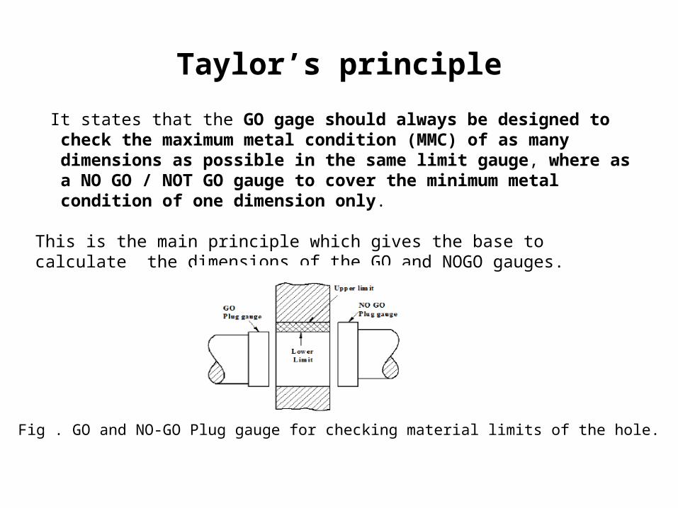
Taylor’s principle
It states that the GO gage should always be designed to check the maximum metal condition (MMC) of as many dimensions as possible in the same limit gauge, where as a NO GO / NOT GO gauge to cover the minimum metal condition of one dimension only.
This is the main principle which gives the base to calculate the dimensions of the GO and NOGO gauges.
Fig . GO and NO-GO Plug gauge for checking material limits of the hole.

Gauge Design
Every gauge is a replica of the part which it inspects for dimension and geometrical limits.1. Taylor’s Principle – Guideline for gauge design
a. Form of “GO” should exactly coincide with the form (shape and size – Geometrically) of a part produced.
b. “GO” end of gauge enables to inspect a part both for dimensional and geometrical limits imposed with maximum material condition.
c. “NO GO” designed for verifying limit imposed on one dimension (minimum metal condition).
Fig. Plug gaugeFig. Snap gauge

Gauge Design - Taylor’s principle
Fig. Plug gauge to check hole dimension
Note: • The length of GO plug gauge should be at least1.5 times the diameter of the
hole in order to check straightness and circularity of bore in any given section ensuring bore alignability, and length of NO GO is kept smaller than GO gauge and red mark is shown.

Gauge Design2. Limit Gauge Tolerance – (a) Manufacturing / Gauge maker’s / Gauge Tolerance (b) Wear
Tolerancea. Gauge Tolerance – is provided in anticipation of imperfection in the workmanship of the
gauge maker. Limit gauges are usually provided with the gauge tolerance of 10% of work tolerance for reference (on either side – totally 20%), master gages and 5% of work tolerance for a inspection gauge as a generally accepted limit. This indicates the limit gauge is 10 times more accurate than the tolerances they are going to control.
b. Wear Tolerance / Allowance – Measuring surfaces wears due to repeated use resulting dimension change in gauge (i.e. change in initial condition/dimension of a gauge). It is desired to increase the service life of a gauge. It must be applied to a “Go” gauge and usually taken as 10% gage tolerance. It is applied in the direction opposite to wear, i.e. in case of a plug gage wear allowance is added while subtracted for a ring/snap gauges.
PS: Bilateral for Inspection gauge to reduce accepting defective parts


Gauge Design
• A gauge can be workshop or inspection or general purpose gauge. Following guidelines are used to allocate Gage tolerance and wear tolerance:
– Component / Part / Work produced in a company should be accepted by the inspection department (i.e. which should lie in the prescribed limit size)
–Component / Part / Work produced should be rejected in case if it lies outside the prescribed limits.
• To implement above guidelines in general two types of gauges are employed in practice.–Workshop gauge – Used during manufacacturing– Inspection gauge – Used for final inspection.
• In case of Master gauge (Used for setting comparator instruments ), the gauge tolerances are distributed bilaterally.

Gauge Design
3. Material considerations – Gauges are made from High carbon and alloy steels and by a special process. Gauge should possess high degree of wear resistance to ensure stable size and shape for longer period (tool life). Gage should be corrosion resistant and have low coefficient of thermal expansion.

Gauges - Classification
• Plain gauge (Used to check plain, i.e. unthreaded holes and shafts) in following ways–According to type
• Standard gauge - exact copy of the part it is inspected, which is in general difficult to manufacture.
• Limit gauges – Widely used in industries, which are made to the limits of the dimensions of the part to be inspected as GO and NO GO.

–According to purpose•Workshop or working gauge – used by operator to check the dimensions, so as to keep the size of the part near the centre of limit of tolerance.
•Inspection gauge – Used by inspector to accept manufactured part when finished, made with slightly larger tolerance, so as to accept parts nearer the tolerance limit.
•Purchase Inspection gauge – Used by purchaser for those parts produced by other plants or outside supplier, limits are equal to the working gauge.
•Reference or Master gauge – used for checking the size and condition of gauges used in the shop floor.

–According to form of tested surface•Plug gauge – to inspect holes•Snap, Gap or Ring gauge – used to inspect shafts.
–According to desine• single limit / double limit•Single ended / double ended•Fixed / Adjustable• Integral end / Renewable end•Solid end / Hollow end
Cylindrical Plug Gauges

Plug Gauges

17
Cylindrical Plug gauge – In Inspection

Taper Plug Gauges
• Used to check size of hole and taper accuracy• Made with standard or special tapers• Some have "go" and "no-go" rings scribed
–gauge fits into hole between two rings means within required tolerance

Plain Ring Gauges
• Used to check outside diameter of pieces• Ground and lapped internally to desired size
–Size stamped on side of gauge• Outside diameter knurled and "no-go" end identified by annular groove on knurled surface• Precautions and procedures similar to those outlined for a plug gauge

Thread Plug Gauges
• Used for checking internal threads of the "go" and "no-go" variety• Based on same principle as cylindrical plug gauges• "go" end (longer end)
–Should be turned in flush to bottom of hole• "no-go" end
–Should just start into hole and become snug before third thread enters

Thread Ring Gauges
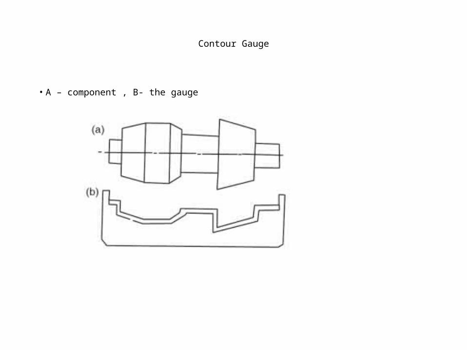
Contour Gauge
• A – component , B- the gauge

Snap Gauges
• One of most common types of comparative measuring instruments• Faster to use than micrometers• Limited in their application• Used to check diameters within certain limits by comparing part size to preset dimension of
snap gauge• Have C-shaped frame with adjustable gauging anvils or rolls set to "go" and
"no-go" limits of the part
• Several styles

Snap Gauges
• A – Double end gauge B- Single end gauge c- Moulded snap gauge D - Moulded snap gauge with ribs

FEELER GAUGE
•A feeler gauge (also known as a thickness gauge) is an accurately manufactured strip of metal that is used to determine the gap or clearance between two components.

FEELER GAUGE
• A feeler gauge can be used to check the following:
–Piston ring gap–Piston ring side clearance
–Connecting rod side clearance

Radius Gauge
• A radius gauge is a tool used to measure the radius of an object.
27

Thread Pitch Gauge
• It used to quickly determine the pitch of various threads by matching the teeth on the leaves with teeth on the work.
28

Position Gauge

References
• A T.B. Of Production Enginerring, By P. C. Sharma• Metrology & Measurement By Bewoor