unit-iii: fundamentals of electrical machines
TRANSCRIPT

UNIT-III: Fundamentals of Electrical Machines

TRANSFORMER
Principle of Operation: Mutual inductance and mutual coupling phenomena in transformer
• Construction
• Working
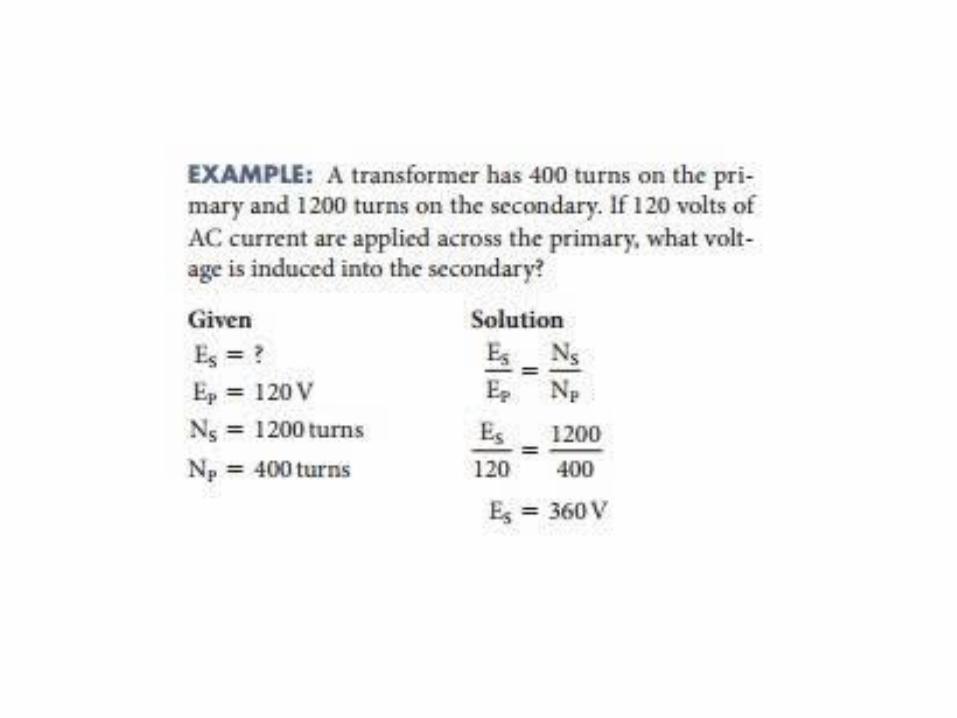
• Concept of Turns Ratio
• Applications
• Transformer on DC
• Autotransformer
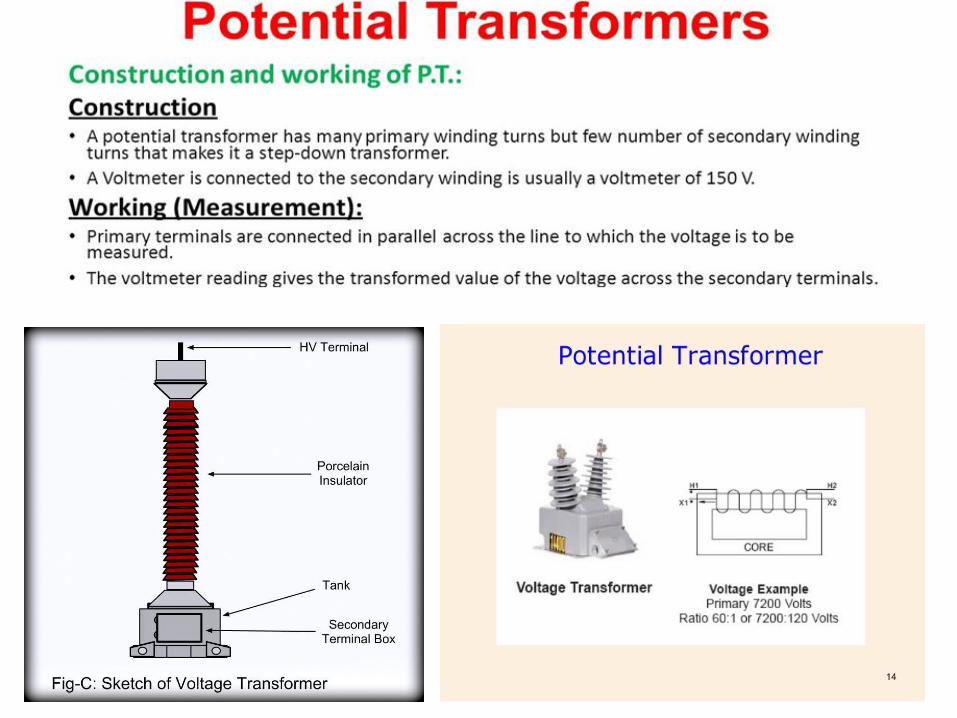
• Instrument transformers

In Brief, A transformer is a static electrical device that
transfers electrical energy between two or
more circuits through electromagnetic induction.


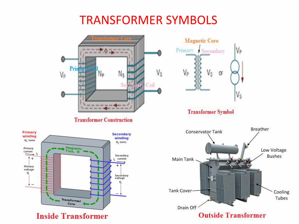
TRANSFORMER SYMBOLS

Principle of operation
It is based onprinciple of MUTUALINDUCTION.According to whichan e.m.f. is inducedin a coil whencurrent in theneighbouring coilchanges.

PRINCIPLE OF TRANSFORMER
It works on the principle of Electromagnetic induction.
The current flowing in the primary winding of the transformers creates a
magnetic field, magnetic flux flows to the secondary side of
the transformers, which induces EMF in the winding and current flows
when the circuit is closed.
A varying current in one coil of the transformer produces a varying magnetic
field, which in turn induces a varying electromotive force (emf) or "voltage" in a
second coil.


TRANSFORMER ON DC SUPPLY
• What will happen if the Primary of a Transformer is Connected to D.C. Supply????


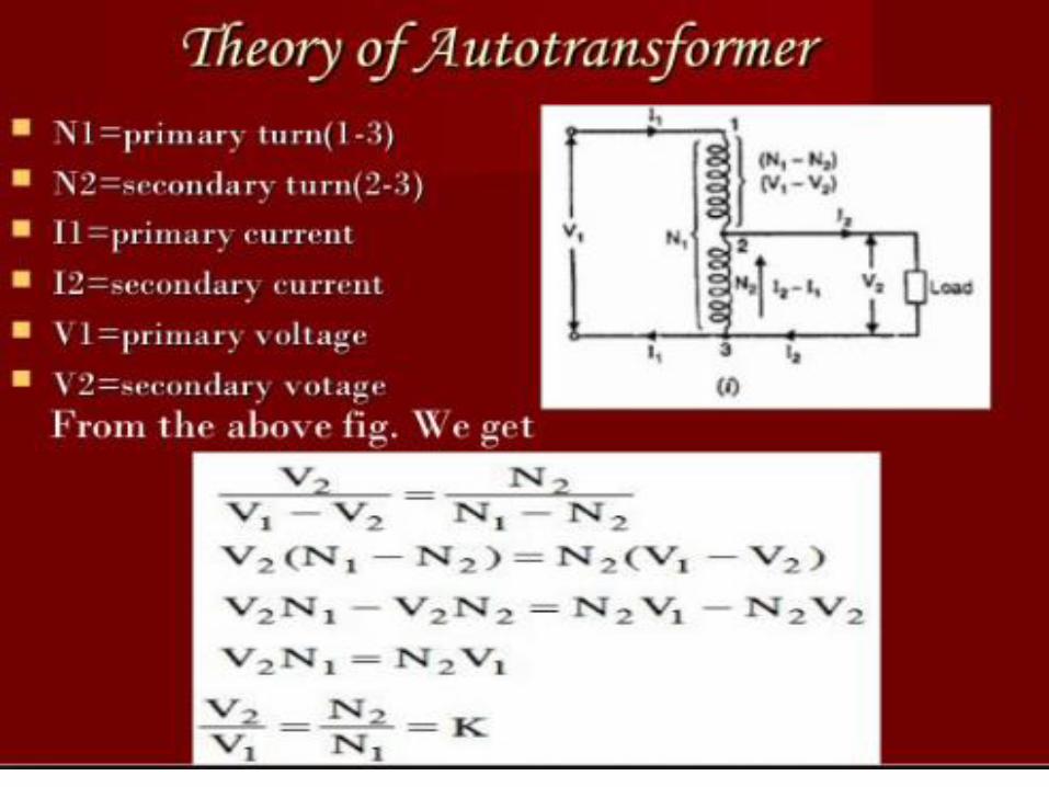
Auto-Transformer An Auto-transformer is an electrical transformer
with only one winding.


DC MACHINES
• DC MOTOR • DC GENERATOR
❑ Working principles
❑ Classification
❑ Starting of DC Machines
❑ Speed control of DC Motor
❑ Applications of dc motors

31
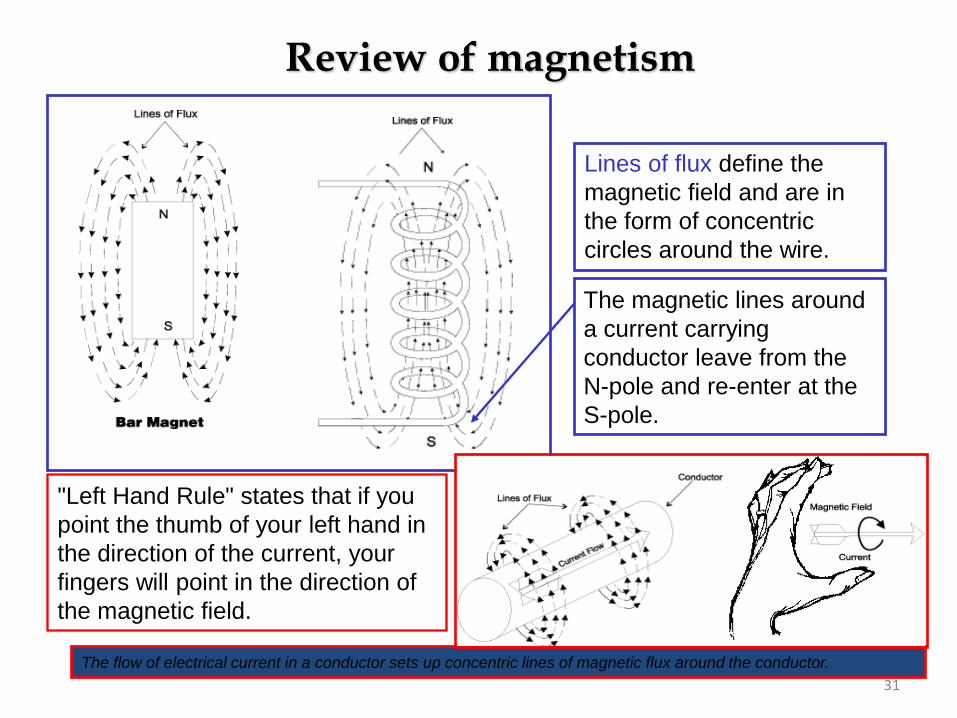
Review of magnetism
The magnetic lines around
a current carrying
conductor leave from the
N-pole and re-enter at the
S-pole.
"Left Hand Rule" states that if you
point the thumb of your left hand in
the direction of the current, your
fingers will point in the direction of
the magnetic field.
Lines of flux define the
magnetic field and are in
the form of concentric
circles around the wire.
The flow of electrical current in a conductor sets up concentric lines of magnetic flux around the conductor.

Fleming’s left hand rule Used to determine the direction of force acting on a current carrying conductor placed in a magnetic field .The middle finger , the fore finger and thumb of the left hand are kept at right angles to one another .
The middle finger represent the direction of current
The fore finger represent the direction of magnetic field
The thumb will indicate the direction of force acting on the conductor .
This rule is used in motors.

Fleming’s left hand rule

Fleming’s left hand rule Used to determine the direction of force acting on a current carrying conductor placed in a magnetic field .The middle finger , the fore finger and thumb of the left hand are kept at right angles to one another .
The middle finger represent the direction of current
The fore finger represent the direction of magnetic field
The thumb will indicate the direction of force acting on the conductor .
This rule is used in motors.

Fleming’s Right hand rule

What are DC Machines?
➢ Are DC generators that convert mechanical energy to DC electric energy.
➢ Are DC motors that convert DC electric energy to mechanical energy.
❑ DC machine can be used as a motor or as a generator.
❑ DC Machine is most often used for a motor.

❑ DC motors are found in many special industrial environments
Motors drive many types of loads from fans and pumps to
presses and conveyors
❑ The major advantages of dc machines over generators are easy to control speed and torque regulation.
❑ However, their application is limited to mills, mines and trains. As examples, trolleys and underground subway cars may use dc motors.
❑ In the past, automobiles were equipped with dc dynamos to charge their batteries, but now dynamos are replaced by alternators.
DC MOTOR: INTRODUCTION

CONSTRUCTION OF DC MACHINES
DC motor stator Rotor of a dc motor

COMPONENTS OF DC MACHINE
40
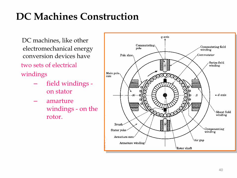
DC Machines Construction
DC machines, like other
electromechanical energy conversion devices have
two sets of electrical
windings
– field windings -on stator
– amarture windings - on the rotor.
.
41
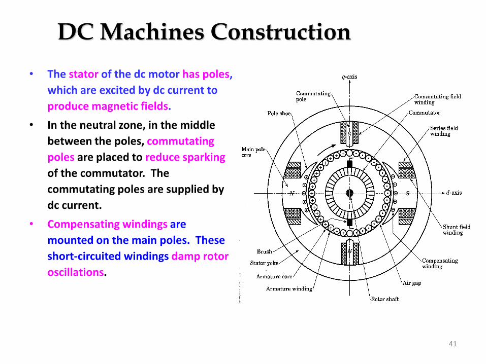
DC Machines Construction
• The stator of the dc motor has poles,
which are excited by dc current to
produce magnetic fields.
• In the neutral zone, in the middle
between the poles, commutating
poles are placed to reduce sparking
of the commutator. The
commutating poles are supplied by
dc current.
• Compensating windings are
mounted on the main poles. These
short-circuited windings damp rotor
oscillations.

42
DC Machines Construction
• The poles are mounted on an iron
core that provides a closed magnetic
circuit.
• The motor housing supports the iron
core, the brushes and the bearings.
• The rotor has a ring-shaped
laminated iron core with slots.
• Coils with several turns are placed in
the slots. The distance between the
two legs of the coil is about 180
electric degrees.

43
DC Machines Construction
• The coils are connected in series through the commutator segments.
• The ends of each coil are connected to a commutator segment.
• The commutator consists of insulated copper segments mounted on an insulated tube.
• Two brushes are pressed to the commutator to permit current flow.
• The brushes are placed in the neutral zone, where the magnetic field is close to zero, to reduce arcing.

44
DC Machines Construction
• The commutator switches the current from one rotor coil to the adjacent coil,
• The switching requires the interruption of the coil current.
• The sudden interruption of an inductive current generates high voltages .
• The high voltage produces flashover and arcing between the commutator segment and the brush.

45
Principle of Operation
The generated voltage of a DC machines having (p) poles and (Z)
conductors on the armature with (a) parallel path between brushes as below :
=
= K
a
pZEA
2where K = pZ /(2πa) = machine constant
The mechanical torque which also equal to electromagnetic torque, is found
as follows:
AAA
me IKIE
===
In the case of a generator, m is the input mechanical torque, which is converted
to electrical power. For the motor, e is developed electromagnetic torque, which
used to drive the mechanical load.

46
ARMATURE winding are defined as the
winding which a voltage is induced.
FIELD windings are defined as the windings
that produce the main flux in the machines.
The magnetic field of the field winding is
approximately sinusoidal, thus AC voltage is
induced in the armature winding as the rotor
turns under the magnetic field of stator.
The COMMUTATOR and BRUSH
combination converts the AC generated
voltages to DC.
Principle of Operation

48
WORKING OF DC MOTOR

49
Current in DC Motor

50
Magnetic Field in DC Motor

51
Force in DC Motor
Chap 2: DC Machines 52
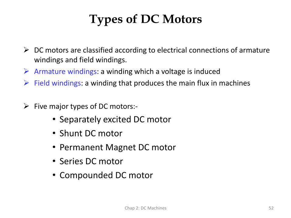
Types of DC Motors
➢ DC motors are classified according to electrical connections of armature windings and field windings.
➢ Armature windings: a winding which a voltage is induced
➢ Field windings: a winding that produces the main flux in machines
➢ Five major types of DC motors:-
• Separately excited DC motor
• Shunt DC motor
• Permanent Magnet DC motor
• Series DC motor
• Compounded DC motor

Types of DC Machines
Self-excited DC machine: when a machine supplies its own
excitation of the field windings. In this machine, residual
magnetism must be present in the ferromagnetic circuit of the
machine in order to start the self-excitation process.
Separately-excited DC machine: The field windings may be
separately excited from an eternal DC source.
Shunt Machine: armature and field circuits are connected in
parallel. Shunt generator can be separately-excited or self-excited.
Series Machine: armature and field circuits are connected in series.
Applications of DC Motors
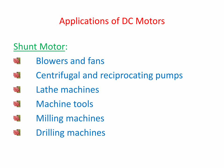
Shunt Motor:
Blowers and fans
Centrifugal and reciprocating pumps
Lathe machines
Machine tools
Milling machines
Drilling machines
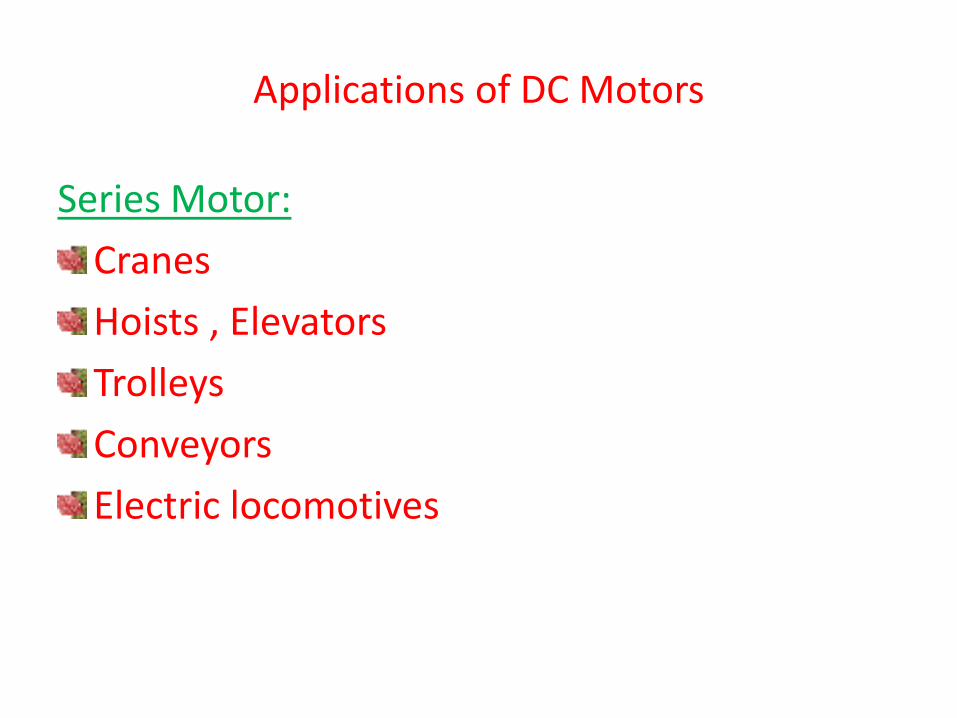
Series Motor:
Cranes
Hoists , Elevators
Trolleys
Conveyors
Electric locomotives
Applications of DC Motors

Cumulative compound Motor:
Rolling mills
Punches
Shears
Heavy planers
Elevators
Applications of DC Motors

Chap 2: DC Machines 57
DC Generators
DC generators are dc machines used as generator. There are five major types of
dc generators, classified according to the manner in which their field flux is
produced:
• Separately excited generator: In separately excited generator, the field flux is derived from a separately power source independent of the generator itself.
• Shunt generator: In a shunt generator, the field flux is derived by connecting the field circuit directly across the terminals of the generators.
• Series generator: In a series generator, the field flux is produced by connecting the field circuit in series with the armature of the generator.
• Cumulatively compounded generator: In a cumulatively compounded generator, both a shunt and series field is present, and their effects are additive.
• Differentially compounded generator: In differentially compounded generator: In a differentially compounded generator, both a shunt and a series field are present, but their effects are subtractive.


59
DC GENERATOR: Generation of Unidirectional Voltage
As the rotor is rotated at an angular velocity
(), the armature flux linkage () change
and a voltage eaa’ is induced between
terminal a and a’. The expression for the
voltage induced is given by Faraday’s Law
dt
deaa
−='
Two pole DC generator
a) Flux linkage of coil aa’; b) induced voltage;
c) rectified voltage

60
The internal generated voltage in the DC machines defined as:
= KEA
Where EA = armature voltage
K = motor constant
= flux
= rotation per min
Generation of Unidirectional Voltage

Shunt Generators:
a. in electro plating
b. for battery recharging
c. as exciters for AC generators.
Applications of DC Generator
Series Generators :A. As boostersB. As lighting arc lamps

According to the speed equation of a dc motor
N ∞ Eb/φ
∞ V- Ia Ra/ φ
Thus speed can be controlled by:
Flux control method: By Changing the flux bycontrolling the current through the fieldwinding.
Armature control method: By Changing thearmature resistance which in turn changesthe voltage applied across the armature
Speed Control of DC motors

Advantages:
It provides relatively smooth and easy control
Speed control above rated speed is possible
As the field winding resistance is high the field current is small. Power loss in the external resistance is small . Hence this method is economical
Disadvantages:
Flux can be increased only upto its rated value
High speed affects the commutation, motor operation becomes unstable
Flux Control Method

Armature Voltage Control Method
The speed is directly proportional to the voltage applied across the armature .
Voltage across armature can be controlled by adding a variable resistance in series with the armature
Potential Divider Control
If the speed control from zero to the rated speed isrequired , by rheostatic method then the voltageacross the armature can be varied by connectingrheostat in a potential divider arrangement .

An induction motor or asynchronous motor is an AC electric motor in whichthe electric current in the rotor needed to produce torque is obtained byelectromagnetic induction from the magnetic field of the stator winding
INDUCTION MOTORS

66
Single Phase Induction Motor▪ The single-phase induction machine is the most frequently
used motor for refrigerators, washing machines, clocks, drills, compressors, pumps, and so forth.
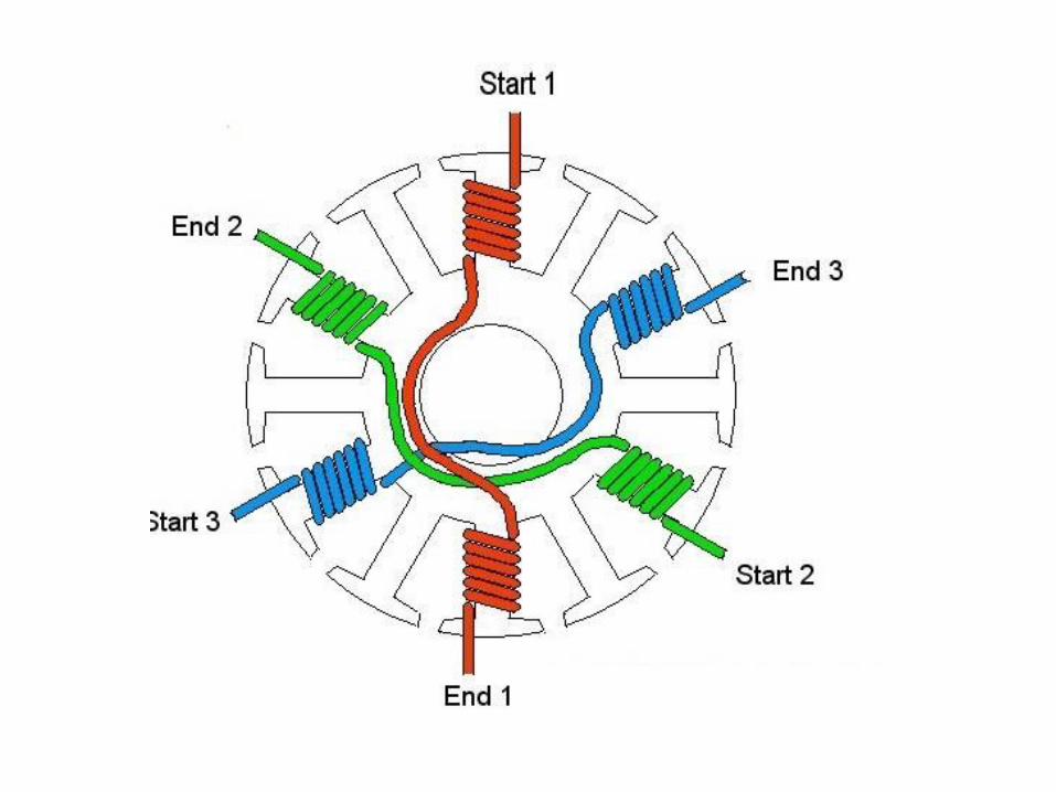
▪ The single-phase motor stator has a laminated iron core
with two windings arranged perpendicularly.
▪ One is the main and
▪ The other is the auxiliary winding or starting winding

67
Construction of Single Phase Induction Motor

10/11/2021
Single Phase Induction Motor
• This “single-phase” motors are truly two-phase machines.
• The motor uses a squirrel cage rotor, which has a laminated iron core with slots.
• Aluminum bars are molded on the slots and short-circuited at both
ends with a ring.
Stator with laminated
iron core Slots with winding
Bars
Ring to short
circuit the barsStarting winding
+
_
Main winding
Rotor with
laminated
iron core+
_
Single-phase induction motor.

10/11/2021
Single Phase Induction Motor
Squirrel cage rotor

10/11/2021 70
Operating principle

10/11/2021 71
7.6 Single Phase Induction Motor
• The single-phase induction motor operation can be described by two methods:
– Double revolving field theory; and
– Cross-field theory.
• Double revolving theory is perhaps the easier of the two explanations to understand
• Learn the double revolving theory only

10/11/2021 72
Single Phase Induction Motor
Double revolving field theory
• A single-phase ac current supplies the main winding that produces a pulsating magnetic field.
• Mathematically, the pulsating field could be divided into two fields, which are rotating in opposite directions.
• The interaction between the fields and the current induced in the rotor bars generates opposing torque
73
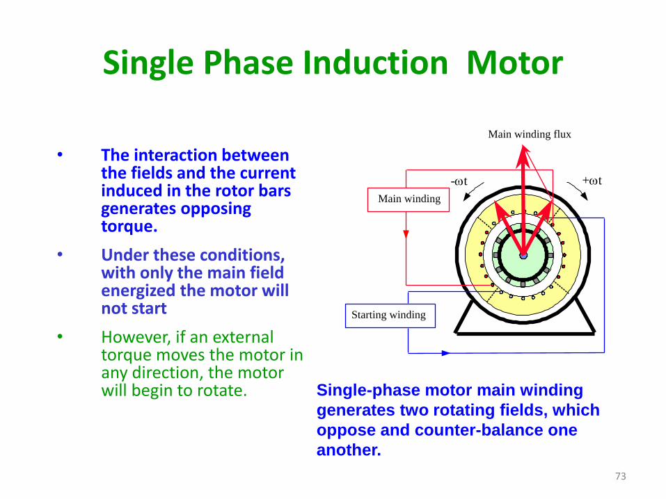
Single Phase Induction Motor
• The interaction between the fields and the current induced in the rotor bars generates opposing torque.
• Under these conditions, with only the main field energized the motor will not start
• However, if an external torque moves the motor in any direction, the motor will begin to rotate.
Starting winding
Main winding
+t-t
Main winding flux
Single-phase motor main winding
generates two rotating fields, which
oppose and counter-balance one
another.


Three Phase Induction Motor


Construction

• Advantages of Three-Phase Induction Motor: These motors are self-starting and use no capacitor, start winding, centrifugal switch or other starting device.
APPLICATIONS
• Three-phase AC induction motors are widely used in industrial and Commercial applications.
