unitypro block library
DESCRIPTION
Block diagram for unity pro plc softwareTRANSCRIPT
Standard
Block Library
07/2011
Unity Pro
© 2011 Schneider Electric. All rights reserved.
Safety Information
Important Information
NOTICE
Read these instructions carefully, and look at the equipment to become familiar with the device before trying to install, operate, or maintain it. The following special messages may appear throughout this documentation or on the equipment to warn of potential hazards or to call attention to information that clarifies or simplifies a procedure.
PLEASE NOTE
Electrical equipment should be installed, operated, serviced, and maintained only by qualified personnel. No responsibility is assumed by Schneider Electric for any consequences arising out of the use of this material. A qualified person is one who has skills and knowledge related to the construction and operation of electrical equipment and its installation, and has received safety training to recognize and avoid the hazards involved.
© 2011 Schneider Electric. All rights reserved.
About the Book
What's in this Part?
This part contains the following chapters:
Document Scope Validity Note Product Related Information Disclaimer
© 2011 Schneider Electric. All rights reserved.
Document Scope
Page 1 of 178Standard library
19/07/2012file://C:\Documents and Settings\Administrator\Local Settings\Temp\~hh5257.htm

This document describes the functions and function blocks of the Standard library.
© 2011 Schneider Electric. All rights reserved.
Validity Note
This document is valid from Unity Pro v6.0.
© 2011 Schneider Electric. All rights reserved.
Product Related Information
WARNING UNINTENDED EQUIPMENT OPERATION
The application of this product requires expertise in the design and programming of control systems. Only persons with such expertise should be alloweprogram, install, alter, and apply this product.
Follow all local and national safety codes and standards.
Failure to follow these instructions can result in death, serious injury, or equipment damage.
© 2011 Schneider Electric. All rights reserved.
Disclaimer
The information provided in this documentation contains general descriptions and/or technical characteristics of the performance of the products contained herein. This documentation is not intended as a substitute for and is not to be used for determining suitability or reliability of these products for specific user applications. It is the duty of any such user or integrator to perform the appropriate and complete risk analysis, evaluation and testing of the products with respect to the relevant specific application or use thereof. Neither Schneider Electric nor any of its affiliates or subsidiaries shall be responsible or liable for misuse of the information contained herein. If you have any suggestions for improvements or amendments or have found errors in this publication, please notify us. No part of this document may be reproduced in any form or by any means, electronic or mechanical, including photocopying, without express written permission of Schneider Electric. All pertinent state, regional, and local safety regulations must be observed when installing and using this product. For reasons of safety and to help ensure compliance with documented system data, only the manufacturer should perform repairs to components. When devices are used for applications with technical safety requirements, the relevant instructions must be followed. Failure to use Schneider Electric software or approved software with our hardware products may result in injury, harm, or improper operating results. Failure to observe this information can result in injury or equipment damage.
© 2011 Schneider Electric. All rights reserved.
General information
Overview
This section contains general information about the Standard library.
What's in this Part?
This part contains the following chapters:
Block Types and their Applications Availability of the blocks on different hardware platforms
© 2011 Schneider Electric. All rights reserved.
Block Types and their Applications
Overview
This chapter describes the different block types and their applications.
What's in this Chapter?
Page 2 of 178Standard library
19/07/2012file://C:\Documents and Settings\Administrator\Local Settings\Temp\~hh5257.htm

This chapter contains the following topics:
Block Types FFB Structure EN and ENO
© 2011 Schneider Electric. All rights reserved.
Block Types
Block Types
Different block types are used in Unity Pro. The general term for the block types is FFB. There are the following types of block:
Elementary Function (EF) Elementary Function Block (EFB) Derived Function Block (DFB) Procedure
NOTE: Motion Function Blocks are not available on the Quantum platform.
Elementary Function
Elementary functions (EF) have no internal status and one output only. If the input values are the same, the output value is the same for the executions of the function, e.g. the addition of two values gives the same result at every execution. An elementary function is represented in the graphical languages (FBD and LD) as a block frame with inputs and an output. The inputs are represented on the left and the outputs on the right of the frame. The name of the function, i.e. the function type, is shown in the center of the frame. The number of inputs can be increased with some elementary functions. NOTE: The deactivation of an EF (EN=0) causes links connected to its Input/Output to be reset. To transfer the state of the signal do not use a link. A variable must be connected to the EF’s output and must be used to connect the input of the element.
Elementary Function Block
Elementary function blocks (EFB) have an internal status. If the inputs have the same values, the value on the outputs can have another value during the individual executions. For example, with a counter, the value on the output is incremented. An elementary function block is represented in the graphical languages (FBD and LD) as a block frame with inputs and outputs. The inputs are represented on the left and the outputs on the right of the frame. The name of the function block, i.e. the function block type, is shown in the center of the frame. The instance name is displayed above the frame.
Derived Function Block
Derived function blocks (DFBs) have the same properties as elementary function blocks. They are created by the user in the programming languages FBD, LD, IL and/or ST.
Procedure
Procedures are functions with several outputs. They have no internal state. The only difference from elementary functions is that procedures can have more than one output and they support variables of the VAR_IN_OUT data type. Procedures do not return a value. Procedures are a supplement to IEC 61131-3 and must be enabled explicitly. There is no visual difference between procedures and elementary functions.
Submit Feedback
CAUTION UNEXPECTED BEHAVIOR OF EQUIPMENT
Do not use links to connect function blocks outputs, when your application relies on persistent output data of an EF.
Failure to follow these instructions can result in injury or equipment damage.
© 2011 Schneider Electric. All rights reserved.
FFB Structure
Structure
Each FFB is made up of an operation (name of the FFB), the operands are required for the operation (formal and actual parameters) and an instance name for elementary/derived function blocks.
Call of a function block in the FBD programming language:
Submit Feedback
Page 3 of 178Standard library
19/07/2012file://C:\Documents and Settings\Administrator\Local Settings\Temp\~hh5257.htm

Formal call of a function block in the ST programming language:
Operation
The operation determines which function is to be executed with the FFB, e.g. shift register, conversion operations.
Operand
The operand specifies what the operation is to be executed with. With FFBs, this consists of formal and actual parameters.
Formal/actual parameters
Inputs and outputs are required to transfer values to or from an FFB. These are called formal parameters. Objects are linked to formal parameters; these objects contain the current process states. They are called actual parameters. At program runtime, the values from the process are transferred to the FFB via the actual parameters and then output again after processing. The data type of the actual parameters must match the data type of the input/output (formal parameters). The only exceptions are generic inputs/outputs whose data type is determined by the actual parameter. If the actual parameters consist of literals, a suitable data type is selected for the function block.
FFB Call in IL/ST
In text languages IL and ST, FFBs can be called in formal and in informal form. Details can be found in the Reference manual. Example of a formal function call: out:=LIMIT (MN:=0, IN:=var1, MX:=5); Example of an informal function call: out:=LIMIT (0, var1, 5); NOTE: The use of EN and ENO is only possible for formal calls.
VAR_IN_OUT variable
FFBs are often used to read a variable at an input (input variables), to process it and to output the altered values of the same variable (output variables). This special type of input/output variable is also called a VAR_IN_OUT variable.
The input and output variable are linked in the graphic languages (FBD and LD) using a line showing that they belong together.
Function block with VAR_IN_OUT variable in FBD:
Function block with VAR_IN_OUT variable in ST: MY_EXAMP1 (IN1:=Input1, IN2:=Input2, IO1:=Comb_IN_OUT, OUT1=>Output1, OUT2=>Output2); The following points must be considered when using FFBs with VAR_IN_OUT variables:
The VAR_IN_OUT inputs must be assigned a variable. Literals or constants cannot be assigned to VAR_IN_OUT inputs/outputs.
CAUTION UNEXPECTED APPLICATION BEHAVIOR
Do not call several times the same block instance within a PLC cycle
Failure to follow these instructions can result in injury or equipment damage.
Page 4 of 178Standard library
19/07/2012file://C:\Documents and Settings\Administrator\Local Settings\Temp\~hh5257.htm

The following additional limitations apply to the graphic languages (FBD and LD):
When using graphic connections, VAR_IN_OUT outputs can only be connected with VAR_IN_OUT inputs. Only one graphical link can be connected to a VAR_IN_OUT input/output. Different variables/variable components can be connected to the VAR_IN_OUT input and the VAR_IN_OUT output. In this case the value of the
variables/variable component on the input is copied to the output variables/variable component. No negations can be used on VAR_IN_OUT inputs/outputs. A combination of variable/address and graphic connections is not possible for VAR_IN_OUT outputs.
© 2011 Schneider Electric. All rights reserved.
EN and ENO
Description
An EN input and an ENO output can be configured for the FFBs.
If the value of EN is equal to "0" when the FFB is invoked, the algorithms defined by the FFB are not executed and ENO is set to "0".
If the value of EN is equal to "1" when the FFB is invoked, the algorithms defined by the FFB will be executed. After the algorithms have been executed successfully, the value of ENO is set to "1". If certain error conditions are detected when executing these algorithms, ENO is set to "0".
If the EN pin is not assigned a value, when the FFB is invoked, the algorithm defined by the FFB is executed (same as if EN equals to "1"), Please refer to Maintain output links on disabled EF. If the algorithms are executed successfully, then value of ENO is set to "1", else ENO is set to "0". If ENO is set to "0" (caused by EN=0 or a detected error condition during execution or unsuccessful algorithm execution):
Function blocks
EN/ENO handling with function blocks that (only) have one link as an output parameter:
If EN from FunctionBlock_1 is set to "0", the output connection OUT from FunctionBlock_1 retains the status it had in the last correctly executed cycle.
EN/ENO handling with function blocks that have one variable and one link as output parameters:
If EN from FunctionBlock_1 is set to "0", the output connection OUT from FunctionBlock_1 retains the status it had in the last correctly executed cycle. The variable OUT1 on the same pin, either retains its previous status or can be changed externally without influencing the connection. The variable and the link are saved independently of each other.
Functions/Procedures As defined in IEC61131-3, the outputs from deactivated functions (EN-input set to "0") is undefined. (The same applies to procedures.) Here is an explanation of the output status in this case:
EN/ENO handling with functions/procedures that (only) have one link as an output parameter:
If EN from Function/Procedure_1 is set to "0", the output connection OUT from Function/Procedure_1 is also set to "0". EN/ENO handling with function blocks that have one variable and one link as output parameters:
If EN from Function/Procedure_1 is set to "0", the output connection OUT from Function/Procedure_1 is also set to "0". The variable OUT1 on the same pin, either retains its previous status or can be changed externally without influencing the connection. The variable and the link are saved independently of each other.
The output behavior of the FFBs does not depend on whether the FFBs are called up without EN/ENO or with EN=1.
Conditional/Unconditional FFB Call
"Unconditional" or "conditional" calls are possible with each FFB. The condition is realized by pre-linking the input EN.
EN connected conditional calls (the FFB is only processed if EN = 1)
EN shown, hidden, and marked TRUE, or shown and not occupied unconditional calls (FFB is processed independent from EN)
NOTE: For disabled function blocks (EN = 0) with an internal time function (e.g. DELAY), time seems to keep running, since it is calculated with the help of a system clock and is therefore independent of the program cycle and the release of the block.
Submit Feedback
CAUTION
UNEXPECTED APPLICATION EQUIPMENT
Page 5 of 178Standard library
19/07/2012file://C:\Documents and Settings\Administrator\Local Settings\Temp\~hh5257.htm

Note for IL and ST
The use of EN and ENO is only possible in the text languages for a formal FFB call, e.g. MY_BLOCK (EN:=enable, IN1:=var1, IN2:=var2, ENO=>error, OUT1=>result1, OUT2=>result2); Assigning the variables to ENO must be done with the operator =>.
With an informal call, EN and ENO cannot be used.
Do not disable function blocks with internal time function during their operation.
Failure to follow these instructions can result in injury or equipment damage.
© 2011 Schneider Electric. All rights reserved.
Availability of the blocks on different hardware platforms
Introduction
Not all blocks are available on all hardware platforms. The blocks available on your hardware platform can be found in the following tables.
Arrays
Availability of the blocks:
CLC_INT
Submit Feedback
Block name Block type defined in IEC 61131-3 M340 Premium Quantum
ADD_***_*** EF - + + +
AND_***_*** EF - + + +
COPY_***_*** EF - + + +
DIV_***_*** EF - + + +
EQUAL_*** EF - + + +
FIND_EQ_*** EF - + + +
FIND_EQP_*** EF - + + +
FIND_GT_*** EF - + + +
FIND_LT_*** EF - + + +
LENGHT_*** EF - + + +
MAX_*** EF - + + +
MIN_*** EF - + + +
MOD_***_*** EF - + + +
MOVE_***_*** (direct assignment) Procedure - + + +
MOVE_***_*** (conversion) Procedure - + + +
MUL_***_*** EF - + + +
NOT_*** EF - + + +
OCCUR_*** EF - + + +
OR_***_*** EF - + + +
ROL_*** Procedure - + + +
ROR_*** Procedure - + + +
SORT_*** Procedure - + + +
SUB_***_*** EF - + + +
SUM_*** EF - + + +
SWAP_*** Procedure - + + +
XOR_***_*** EF - + + +
Legend:
+ Yes
- No
Page 6 of 178Standard library
19/07/2012file://C:\Documents and Settings\Administrator\Local Settings\Temp\~hh5257.htm

Availability of the blocks:
Comparison
Availability of the blocks:
Date & Time
Availability of the blocks:
Logic
Availability of the blocks:
Block name Block type defined in IEC 61131-3 M340 Premium Quantum
PID_INT Procedure - + + +
PWM_INT Procedure - + + +
SERVO_INT Procedure - + + +
Legend:
+ Yes
- No
Block name Block type defined in IEC 61131-3 M340 Premium Quantum
EQ EF + + + +
GE EF + + + +
GT EF + + + +
LE EF + + + +
LT EF + + + +
NE EF + + + +
Legend:
+ Yes
- No
Block name Block type defined in IEC 61131-3 M340 Premium Quantum
ADD_***_TIME EF + + + +
DIVTIME EF + + + +
MULTIME EF + + + +
SUB_***_*** EF + + + +
SUB_***_TIME EF + + + +
Legend:
+ Yes
- No
Block name Block type defined in IEC 61131-3 M340 Premium Quantum
AND EF + + + +
F_TRIG EFB + + + +
FE EF - + + +
NOT EF + + + +
OR EF + + + +
R_TRIG EFB + + + +
RE EF - + + +
RESET Procedure - + + +
ROL EF + + + +
ROR EF + + + +
RS EFB + + + +
Procedure - + + +
Page 7 of 178Standard library
19/07/2012file://C:\Documents and Settings\Administrator\Local Settings\Temp\~hh5257.htm

Mathematics
Availability of the blocks:
Statistical
Availability of the blocks:
SET
SHL EF + + + +
SHR EF + + + +
SR EFB + + + +
TRIGGER EFB - + + +
XOR EF + + + +
Legend:
+ Yes
- No
Block name Block type defined in IEC 61131-3 M340 Premium Quantum
ABS EF + + + +
ACOS EF + + + +
ADD EF + + + +
ADD_TIME EF + + + +
ASIN EF + + + +
ATAN EF + + + +
COS EF + + + +
DEC Procedure - + + +
DIV EF + + + +
DIVMOD Procedure - + + +
EXP EF + + + +
EXPT_REAL EF + + + +
INC Procedure - + + +
LN EF + + + +
LOG EF + + + +
MOD EF + + + +
MOVE EF + + + +
MUL EF + + + +
NEG EF - + + +
SIGN EF - + + +
SIN EF + + + +
SQRT EF DINT: -
INT: -
REAL: +
+ + +
SUB EF + + + +
SUB_TIME EF + + + +
TAN EF + + + +
Legend:
+ Yes
- No
Block name Block type defined in IEC 61131-3 M340 Premium Quantum
AVE EF - + + +
Page 8 of 178Standard library
19/07/2012file://C:\Documents and Settings\Administrator\Local Settings\Temp\~hh5257.htm

Strings
Availability of the blocks:
Timers & Counter
Availability of the blocks:
Type to Type
Availability of the blocks:
LIMIT EF + + + +
LIMIT_IND Procedure - + + +
MAX EF + + + +
MIN EF + + + +
MUX EF + + + +
SEL EF + + + +
Legend:
+ Yes
- No
Block name Block type defined in IEC 61131-3 M340 Premium Quantum
CONCAT_STR EF - + + +
DELETE_INT EF + + + +
EQUAL_STR EF + + + +
FIND_INT EF + + + +
INSERT_INT EF + + + +
LEFT_INT EF + + + +
LEN_INT EF + + + +
MID_INT EF + + + +
REPLACE_INT EF + + + +
RIGHT_INT EF + + + +
Legend:
+ Yes
- No
Block name Block type defined in IEC 61131-3 M340 Premium Quantum
CTD EFB + + + +
CTD_*** EFB - + + +
CTU EFB + + + +
CTU_*** EFB - + + +
CTUD EFB + + + +
CTUD_*** EFB - + + +
TOF EFB + + + +
TON EFB + + + +
TP EFB + + + +
Legend:
+ Yes
- No
Block name Block type defined in IEC 61131-3 M340 Premium Quantum
ARINT_TO_DATE EF - + + +
ARINT_TO_DT EF - + + +
Page 9 of 178Standard library
19/07/2012file://C:\Documents and Settings\Administrator\Local Settings\Temp\~hh5257.htm

ARINT_TO_TOD EF - + + +
ASCII_TO_STRING EF - + + +
ASCII_TO_STRING_INV EF - + + +
BCD_TO_INT EF + + + +
BIT_TO_BYTE EF - + + +
BIT_TO_WORD EF - + + +
BOOL_TO_*** EF + + + +
BYTE_AS_WORD EF - + + +
BYTE_TO_BIT Procedure - + + +
BYTE_TO_*** EF + + + +
DATE_TO_ARINT EF + + + +
DATE_TO_STRING EF + + + +
DBCD_TO_*** EF - + + +
DEG_TO_RAD EF - + + +
DINT_AS_WORD Procedure - + + +
DINT_TO_*** EF + + + +
DINT_TO_DBCD EF - + + +
DINT_TO_STRING EF + + + +
DT_TO_ARINT EF + + + +
DT_TO_STRING EF + + + +
DWORD_TO_*** EF + + + +
GRAY_TO_INT EF - + + +
INT_AS_DINT EF - + + +
INT_TO_*** EF + + + +
INT_TO_BCD EF - + + +
INT_TO_DBCD EF - + + +
INT_TO_STRING EF + + + +
RAD_TO_DEG EF - + + +
REAL_AS_WORD Procedure - + + +
REAL_TO_*** EF + + + +
REAL_TO_STRING EF + + + +
REAL_TRUNC_*** EF + + + +
STRING_TO_ASCII EF - + + +
STRING_TO_ASCII_INV EF - + + +
STRING_TO_*** EF + + + +
TIME_AS_WORD Procedure - + + +
TIME_TO_*** EF + + + +
TIME_TO_STRING EF + + + +
TOD_TO_ARINT EF + + + +
TOD_TO_STRING EF + + + +
UDINT_AS_WORD Procedure - + + +
UDINT_TO_*** EF + + + +
UINT_TO_*** EF + + + +
WORD_AS_BYTE Procedure - + + +
WORD_AS_DINT EF - + + +
Page 10 of 178Standard library
19/07/2012file://C:\Documents and Settings\Administrator\Local Settings\Temp\~hh5257.htm
WORD_AS_REAL EF - + + +
WORD_AS_TIME EF - + + +
WORD_AS_UDINT EF - + + +
WORD_TO_BIT Procedure - + + +
WORD_TO_*** EF + + + +
Legend:
+ Yes
- No
© 2011 Schneider Electric. All rights reserved.
Arrays
Overview
This section describes the elementary functions and elementary function blocks of the Arrays family.
What's in this Part?
This part contains the following chapters:
ADD_***_***: Addition of a number to elements of an array or addition of two arrays AND_***_***: Logical AND between arrays and variables COPY_•••••_•••••: Copy on arrays DIV_***_***: Division of arrays EQUAL_***: Comparison of two arrays FIND_EQ_***: First element of an array equal to a given value FIND_EQP_***: First element of an array equal to a value starting from a given rank FIND_GT_***: First element of an array greater than a given value FIND_LT_***: First element of an array less than a given value LENGTH_***: Length of an array MAX_***: Maximum value of array elements MIN_***: Minimum value of array elements MOD_***_***: Remainder of division of arrays MOVE_***_***: Assignment to arrays MOVE_***_***: Array conversion MUL_***_***: Multiplication of arrays NOT_***: Logical negation of arrays OCCUR_***: Occurrence of a value in an array OR_***_***: Logical OR between arrays and variables ROL_***: Rotate shift to left ROR_***: Rotate shift to right SORT_***: Ascending or descending sort SUB_***_***: Subtraction from arrays SUM_***: Sum of array elements SWAP_***: Permutation of the bytes of an array XOR_***_***: Exclusive OR between arrays
© 2011 Schneider Electric. All rights reserved.
ADD_***_***: Addition of a number to elements of an array or addition of two arrays
Function description
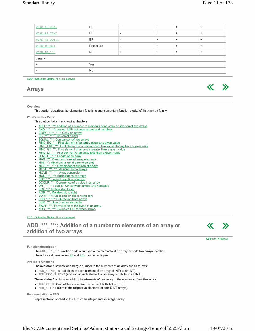
The ADD_***_*** function adds a number to the elements of an array or adds two arrays together.
The additional parameters EN and ENO can be configured.
Available functions
The available functions for adding a number to the elements of an array are as follows:
ADD_ARINT_INT (addition of each element of an array of INTs to an INT). ADD_ARDINT_DINT (addition of each element of an array of DINTs to a DINT).
The available functions for adding the elements of one array to the elements of another array:
ADD_ARINT (Sum of the respective elements of both INT arrays). ADD_ARDINT (Sum of the respective elements of both DINT arrays).
Representation in FBD
Representation applied to the sum of an integer and an integer array:
Submit Feedback
Page 11 of 178Standard library
19/07/2012file://C:\Documents and Settings\Administrator\Local Settings\Temp\~hh5257.htm

Representation in LD
Representation applied to the sum of an integer and an integer array:
Representation in IL
Representation applied to the sum of an integer and an integer array: LD Input_IN1 ADD_ARINT_INT Input_IN2 ST Array1
Representation in ST
Representation applied to the sum of an integer and an integer array: Array1 := ADD_ARINT_INT(Input_IN1,Input_IN2);
Description of parameters
The following table describes the input parameters:
The following table describes the output parameters:
Runtime errors
The management of the %S18 system bit is identical to that for operations on words or double words. If an operation between two elements sets the %S18 bit (overflow or division by zero), the result for this operation is incorrect, but the operation on the following elements is carried out correctly.
Parameter Type Comment
Input_ IN1 ARRAY [n..m] OF INT,
ARRAY [n..m] OF DINT
Input_IN1 is either a single or double integer, or an array of single or double integers, n and m are positive or negative integers or nil.
Input_IN2 INT,
DINT,
ARRAY [n..m] OF INT,
ARRAY [n..m] OF DINT
Input_ IN2 is either a single or double integer, or an array of single or double integers, n and m are positive or negative integers or nil.
Parameter Type Comment
Array1 ARRAY [n..m] OF INT
ARRAY [n..m] OF DINT
According to the type of Input_ IN1 and Input_IN2, each element of Array1 is the sum:
of a single or double integer and the corresponding element of an array,
the corresponding elements of two arrays.
© 2011 Schneider Electric. All rights reserved.
AND_***_***: Logical AND between arrays and variables
Function description
The AND_***_*** function carries out a logical AND (bit to bit) between:
the elements of two arrays, between a single type variable and the elements of an array, between the elements of an array and a single type variable.
NOTE: The result is always an array. The additional parameters EN and ENO can be configured.
Available functions
The functions available in the general library are the following:
AND_AREBOOL (logical AND of two EBOOL arrays). AND_ARWORD (logical AND of two WORD arrays). AND_ARWORD_WORD (logical AND of each element of a WORD array with a WORD). AND_ARDWORD_DWORD (logical AND of each element of a DWORD array with a DWORD). AND_ARDWORD (logical AND of two DWORD arrays).
Submit Feedback
Page 12 of 178Standard library
19/07/2012file://C:\Documents and Settings\Administrator\Local Settings\Temp\~hh5257.htm
The functions available in the Obsolete library are the following:
AND_ARINT_INT (logical AND of each element of an INT array with an INT). AND_ARDINT_DINT (logical AND of each element of a DINT array with a DINT). AND_ARINT (logical AND of each element of an INT array with each element corresponding to another INT array). AND_ARDINT (logical AND of each element of an INT array with each element corresponding to another DINT array).
Representation in FBD
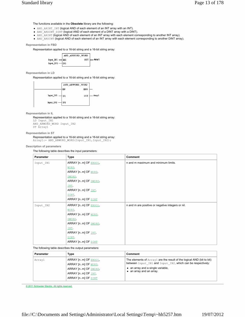
Representation applied to a 16-bit string and a 16-bit string array:
Representation in LD
Representation applied to a 16-bit string and a 16-bit string array:
Representation in IL
Representation applied to a 16-bit string and a 16-bit string array: LD Input_IN1 AND_ARWORD_WORD Input_IN2 ST Array1
Representation in ST
Representation applied to a 16-bit string and a 16-bit string array: Array1:= AND_ARWORD_WORD(Input_IN1,Input_IN2);
Description of parameters
The following table describes the input parameters:
The following table describes the output parameters:
Parameter Type Comment
Input_IN1 ARRAY [n..m] OF EBOOL,
WORD,
ARRAY [n..m] OF WORD,
DWORD,
ARRAY [n..m] OF DWORD,
INT,
ARRAY [n..m] OF INT,
DINT,
ARRAY [n..m] OF DINT
n and m maximum and minimum limits.
Input_IN2 ARRAY [n..m] OF EBOOL,
WORD,
ARRAY [n..m] OF WORD,
DWORD,
ARRAY [n..m] OF DWORD,
INT,
ARRAY [n..m] OF INT,
DINT,
ARRAY [n..m] OF DINT
n and m are positive or negative integers or nil.
Parameter Type Comment
Array1 ARRAY [n..m] OF EBOOL,
ARRAY [n..m] OF WORD,
ARRAY [n..m] OF DWORD,
ARRAY [n..m] OF INT,
ARRAY [n..m] OF DINT
The elements of Array1 are the result of the logical AND (bit to bit) between Input_IN1 and Input_IN2, which can be respectively:
an array and a single variable, an array and an array.
© 2011 Schneider Electric. All rights reserved.
Page 13 of 178Standard library
19/07/2012file://C:\Documents and Settings\Administrator\Local Settings\Temp\~hh5257.htm

COPY_•••••_•••••: Copy on arrays
Function description
The COPY_•••••_••••• function copies a series of contiguous elements from one array into another array. The arrays are of different or identical types and the target zone is fixed by the parameters of the function. The additional parameters EN and ENO can be configured.
NOTE: The COPY_•••••_••••• function can result in unintended data values. For example, copying input values on output values can lead to corrupted data and unexpected behavior of the application.
Available functions
The available functions are as follows:
COPY_AREBOOL_ARINT, COPY_AREBOOL_AREBOOL, COPY_AREBOOL_ARDINT, COPY_ARINT_AREBOOL, COPY_ARDINT_AREBOOL.
Representation in FBD
Representation applied to the assignment of a zone of an integer array to a zone of a bit array:
Representation in LD
Representation applied to the assignment of a zone of an integer array to a zone of a bit array:
Representation in IL
Representation applied to the assignment of a zone of an integer array to a zone of a bit array: LD Array1 COPY_ARINT_AREBOOL Begin_Row, Element_Number, Destination_Row ST Result_Array
Representation in ST
Representation applied to the assignment of a zone of an integer array to a zone of a bit array: Result_Array := COPY_ARINT_AREBOOL(Array1, Begin_Row, Element_Number, Destination_Row);
Description of parameters
The following table describes the input parameters:
Submit Feedback
WARNING UNEXPECTED APPLICATION BEHAVIOR
Check that data being written in the target array is valid when using the COPY_•••••_••••• function.
Failure to follow these instructions can result in death, serious injury, or equipment damage.
Parameter Type Comment
Array1 ARRAY [n..m] OF EBOOL,
ARRAY [n..m] OF INT,
ARRAY [n..m] OF DINT
n and m are positive or negative integers or nil.
Begin_Row INT Rank of first element to be copied from the array Array1.
Note: The first element of the array has the rank 0.
Element_Number INT Number of elements to be copied from the array Array1.
Page 14 of 178Standard library
19/07/2012file://C:\Documents and Settings\Administrator\Local Settings\Temp\~hh5257.htm

The following table describes the output parameters:
NOTE: if the number of elements to be extracted is greater than the remaining size, starting from the rankBegin_Row, the function extracts all the elements fromBegin_Row to the last element of the array. If the number of elements to be extracted is greater than the space available starting from the rankDestination_Row, the copy function runs to the last element of the array. A negative value of Begin_Row, Element_Number and Destination_Row is interpreted as null.
Destination_Row INT Target rank in the array Result_Array.
Parameter Type Comment
Result_Array ARRAY [n..m] OF EBOOL,
ARRAY [n..m] OF INT,
ARRAY [n..m] OF DINT
n and m are positive or negative integers or nil.
Target array which contains the elements selected from Array1.
© 2011 Schneider Electric. All rights reserved.
DIV_***_***: Division of arrays
Function description
The DIV_***_*** function carries out the division:
of a number by the elements of an array, of the elements of an array by a number,
of the elements of an array by the respective elements of another array.
The additional parameters EN and ENO can be configured.
Available functions
The available functions for division of a number by the elements of an array are as follows:
DIV_INT_ARINT, DIV_DINT_ARDINT.
The available functions for division of the elements of an array by a number are as follows:
DIV_ARINT_INT, DIV_ARDINT_DINT.
The available functions for division of the elements of an array by the respective elements of another array are as follows:
DIV_ARINT, DIV_ARDINT.
Representation in FBD
Representation applied to the division of an integer by the elements of an integer array:
Representation in LD
Representation applied to the division of an integer by the elements of an integer array:
Representation in IL
Representation applied to the division of an integer by the elements of an integer array: LD Input_IN1 DIV_INT_ARINT Input_IN2 ST Array1
Representation in ST
Representation applied to the division of an integer by the elements of an integer array: Array1:= DIV_INT_ARINT(Input_IN1,Input_IN2);
Description of parameters
The following table describes the input parameters:
Submit Feedback
Parameter Type Comment
Page 15 of 178Standard library
19/07/2012file://C:\Documents and Settings\Administrator\Local Settings\Temp\~hh5257.htm
The following table describes the output parameters:
Runtime errors
The management of the %S18 system bit is identical to that for operations on words or double words. In the case of division by zero, the value of the result is equal to the value of the numerator. If an operation between two elements sets the %S18 bit (overflow or division by zero), the result for this operation is incorrect, but the operation on the following elements is carried out correctly.
Input_IN1 INT,
DINT,
ARRAY [n..m] OF INT,
ARRAY [n..m] OF DINT
Input_IN1 is either a single or double integer, or an array of single or double integers, n and m are positive or negative integers or nil.
Input_IN2 INT,
DINT,
ARRAY [n..m] OF INT,
ARRAY [n..m] OF DINT
Input_ IN2 is either a single or double integer, or an array of single or double integers, n and m are positive or negative integers or nil.
Parameter Type Comment
Array1 ARRAY [n..m] OF INT
ARRAY [n..m] OF DINT
According to the type of Input_IN1 and Input_IN2, each element of Array1 is the division:
of a single or double integer Input_IN1 by the corresponding element of the array Input_IN2 or else,
of the elements of the array Input_IN1 by single or double integers Input_IN2 or else,
of the elements of the array Input_IN1 by the respective elements of the array Input_ IN2.
© 2011 Schneider Electric. All rights reserved.
EQUAL_***: Comparison of two arrays
Function description
The EQUAL_*** function compares two arrays element by element.
The additional parameters EN and ENO can be configured.
Available functions
The available functions are as follows:
EQUAL_ARWORD, EQUAL_ARDWORD, EQUAL_ARINT, EQUAL_ARDINT, EQUAL_ARREAL.
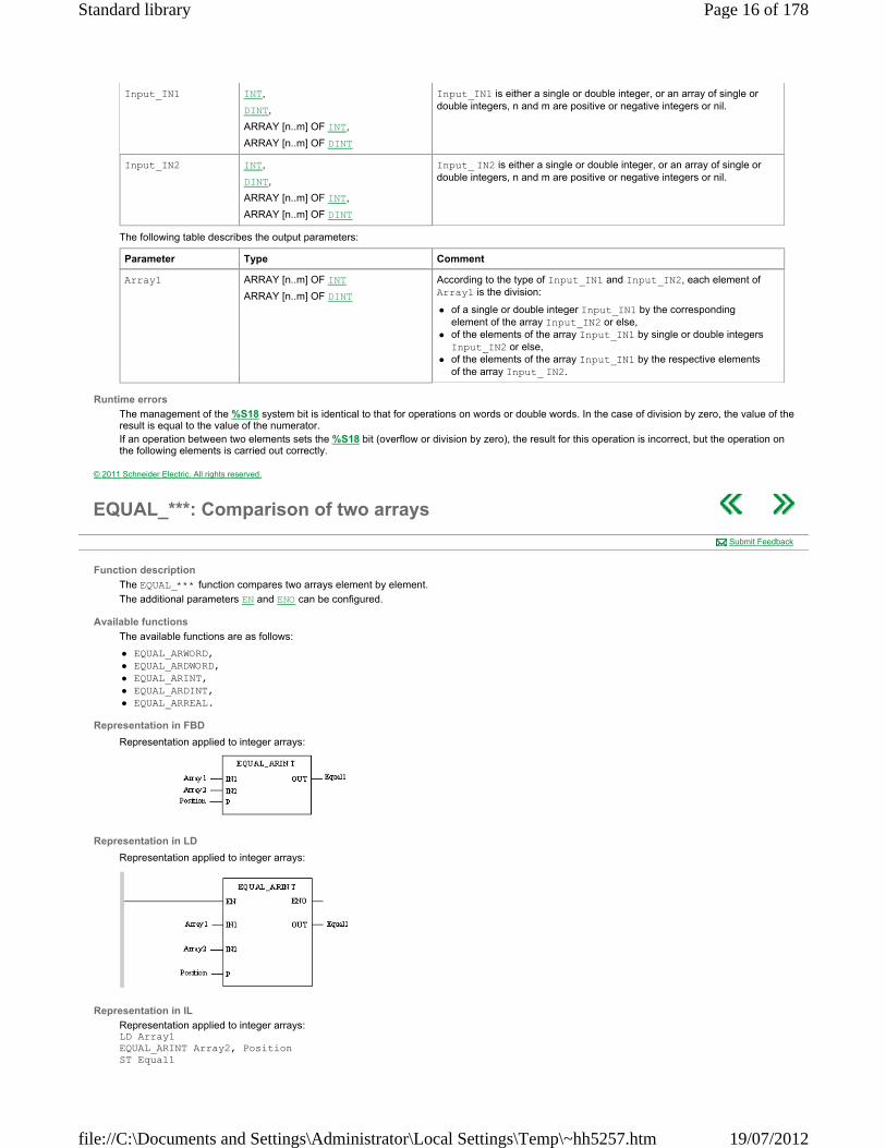
Representation in FBD
Representation applied to integer arrays:
Representation in LD
Representation applied to integer arrays:
Representation in IL
Representation applied to integer arrays: LD Array1 EQUAL_ARINT Array2, Position ST Equal1
Submit Feedback
Page 16 of 178Standard library
19/07/2012file://C:\Documents and Settings\Administrator\Local Settings\Temp\~hh5257.htm

Representation in ST
Representation applied to integer arrays: Equal1:= EQUAL_ARINT(Array1, Array2, Position);
Description of parameters
The following table describes the input parameters:
The following table describes the output parameters:
Runtime errors
When the array contains an invalid value, the result of the function contains -2 and the bit %S18 = 1.
Parameter Type Comment
Array1 ARRAY [n..m] OF WORD
ARRAY [n..m] OF DWORD
ARRAY [n..m] OF INT
ARRAY [n..m] OF DINT
ARRAY [n..m] OF REAL
n and m are positive or negative integers or nil.
Array2 ARRAY [n..m] OF WORD
ARRAY [n..m] OF DWORD
ARRAY [n..m] OF INT
ARRAY [n..m] OF DINT
ARRAY [n..m] OF REAL
n and m are positive or negative integers or nil.
Position INT Rank of first element from which the search is launched.
Parameter Type Comment
Equal1 INT Rank of first different elements. If the two arrays are equivalent, Equal1 = -1.
© 2011 Schneider Electric. All rights reserved.
FIND_EQ_***: First element of an array equal to a given value
Function description
The FIND_EQ_*** function searches for the first element of an array equal to a given value. NOTE: Before starting the search, the block immediately writes -1 to its output OUT to indicate that the value connected to IN2 was not found . Then the block starts the search and updates the output OUT with the rank value of the first element fullfilling the search criteria.
The additional parameters EN and ENO can be configured.
Available functions
The available functions are as follows:
FIND_EQ_ARWORD, FIND_EQ_ARDWORD, FIND_EQ_ARINT, FIND_EQ_ARDINT, FIND_EQ_ARREAL.
Representation in FBD
Representation applied to an integer array:
Representation in LD
Representation applied to an integer array:
Representation in IL
Representation applied to an integer array:
Submit Feedback
Page 17 of 178Standard library
19/07/2012file://C:\Documents and Settings\Administrator\Local Settings\Temp\~hh5257.htm
LD Array1 FIND_EQ_ARINT Value1 ST Row_Value1
Representation in ST
Representation applied to an integer array: Row_Value1:= FIND_EQ_ARINT(Array1, Value1);
Description of parameters
The following table describes the input parameters:
The following table describes the output parameters:
Runtime errors
When the array contains an invalid value or if Value1 is an invalid value, the result of the function contains-2 and the bit %S18 = 1.
Parameter Type Comment
Array1 ARRAY [n..m] OF INT
ARRAY [n..m] OF DINT
ARRAY [n..m] OF WORD
ARRAY [n..m] OF DWORD
ARRAY [n..m] OF REAL
n and m are positive or negative integers or nil.
Value1 INT, DINT, WORD, DWORD, REAL. Value whose rank is searched for in Array1.
Of the same type as the elements of the array Array 1.
Parameter Type Comment
Row_Value1 INT Rank of first element of Array1 equal to Value1. If none of the elements of the array is equal to Value1, Row_Value1 = -1
© 2011 Schneider Electric. All rights reserved.
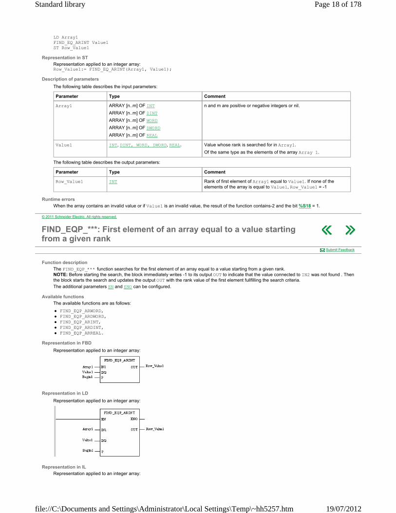
FIND_EQP_***: First element of an array equal to a value starting from a given rank
Function description
The FIND_EQP_*** function searches for the first element of an array equal to a value starting from a given rank. NOTE: Before starting the search, the block immediately writes -1 to its output OUT to indicate that the value connected to IN2 was not found . Then the block starts the search and updates the output OUT with the rank value of the first element fullfilling the search criteria.
The additional parameters EN and ENO can be configured.
Available functions
The available functions are as follows:
FIND_EQP_ARWORD, FIND_EQP_ARDWORD, FIND_EQP_ARINT, FIND_EQP_ARDINT, FIND_EQP_ARREAL.
Representation in FBD
Representation applied to an integer array:
Representation in LD
Representation applied to an integer array:
Representation in IL
Representation applied to an integer array:
Submit Feedback
Page 18 of 178Standard library
19/07/2012file://C:\Documents and Settings\Administrator\Local Settings\Temp\~hh5257.htm
LD Array1 FIND_EQP_ARINT Value1, Begin1 ST Row_Value1
Representation in ST
Representation applied to an integer array: Row_Value1:= FIND_EQP_ARINT(Array1, Value1, Begin1);
Description of parameters
The following table describes the input parameters:
The following table describes the output parameters:
Runtime errors
When the array contains an invalid value or if Value1 is an invalid value, the result of the function contains-2 and the bit %S18 = 1.
Parameter Type Comment
Array1 ARRAY [n..m] OF WORD
ARRAY [n..m] OF DWORD
ARRAY [n..m] OF INT
ARRAY [n..m] OF DINT
ARRAY [n..m] OF REAL
n and m are positive or negative integers or nil.
Value1 WORD, DWORD, INT, DINT, REAL. Value whose rank is searched for in Array1.
Of the same type as the elements of the array Array 1.
Begin1 ... INT Rank the search starts from
Parameter Type Comment
Row_Value1 INT Rank of first element of Array1 equal to Value1. If none of the elements of the array is equal to Value1, Row_Value1 = -1
Note: Row_Value1 indicates the rank in relation to the start of the array.
© 2011 Schneider Electric. All rights reserved.
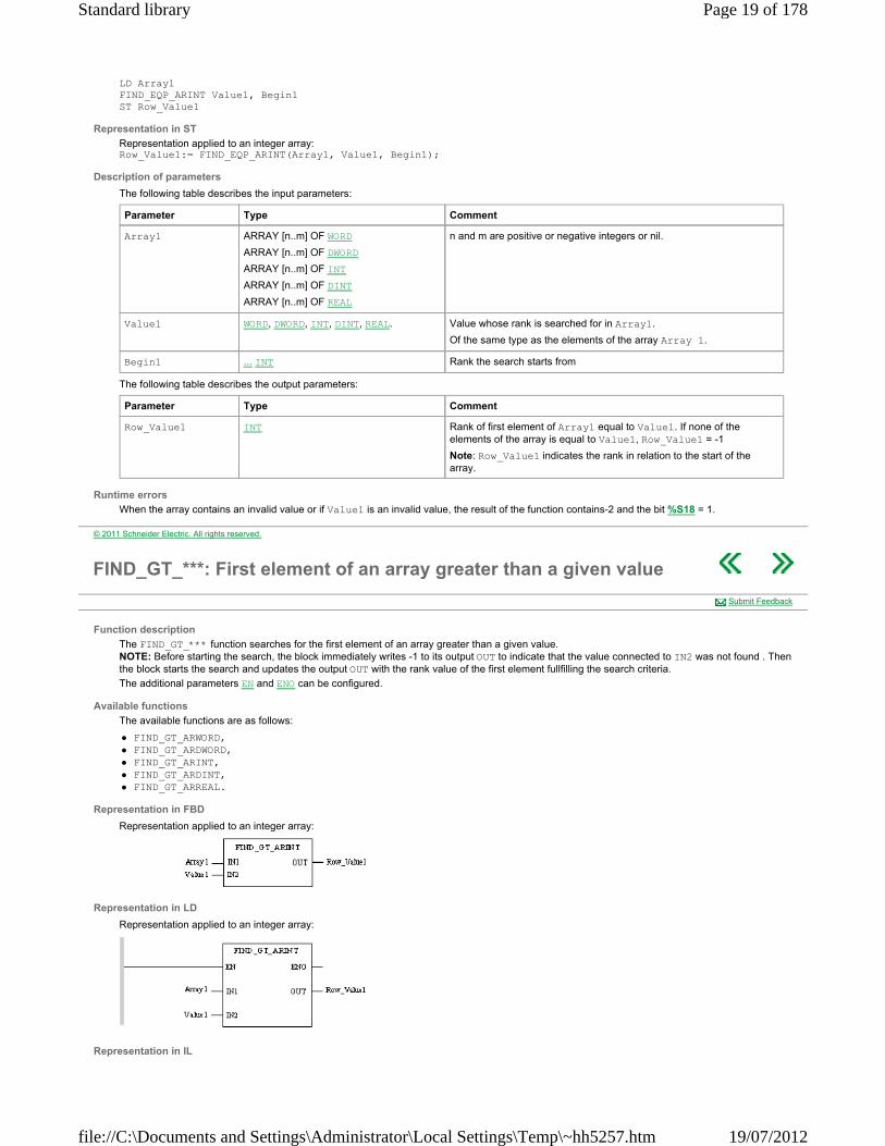
FIND_GT_***: First element of an array greater than a given value
Function description
The FIND_GT_*** function searches for the first element of an array greater than a given value. NOTE: Before starting the search, the block immediately writes -1 to its output OUT to indicate that the value connected to IN2 was not found . Then the block starts the search and updates the output OUT with the rank value of the first element fullfilling the search criteria.
The additional parameters EN and ENO can be configured.
Available functions
The available functions are as follows:
FIND_GT_ARWORD, FIND_GT_ARDWORD, FIND_GT_ARINT, FIND_GT_ARDINT, FIND_GT_ARREAL.
Representation in FBD
Representation applied to an integer array:
Representation in LD
Representation applied to an integer array:
Representation in IL
Submit Feedback
Page 19 of 178Standard library
19/07/2012file://C:\Documents and Settings\Administrator\Local Settings\Temp\~hh5257.htm

Representation applied to an integer array: LD Array1 FIND_GT_ARINT Value1 ST Row_Value1
Representation in ST
Representation applied to an integer array: Row_Value1:= FIND_GT_ARINT(Array1, Value1);
Description of parameters
The following table describes the input parameters:
The following table describes the output parameters:
Runtime errors
When the array contains an invalid value or if Value1 is an invalid value, the result of the function contains-2 and the bit %S18 = 1.
Input Type Comment
Array1 ARRAY [n..m] OF WORD
ARRAY [n..m] OF DWORD
ARRAY [n..m] OF INT
ARRAY [n..m] OF DINT
ARRAY [n..m] OF REAL
n and m are positive or negative integers or nil.
Value1 WORD, DWORD, INT , DINT, REAL Value for which the rank of the first greater value is searched for in Array1.
Of the same type as the elements of the array Array 1.
Output Type Comment
Row_Value1 INT Rank of the first element of Array1 > than Value1. If none of the elements of the array is greater than Value1, Row_Value1 = -1
© 2011 Schneider Electric. All rights reserved.
FIND_LT_***: First element of an array less than a given value
Function description
The FIND_LT_*** function searches for the first element of an array less than a given value. NOTE: Before starting the search, the block immediately writes -1 to its output OUT to indicate that the value connected to IN2 was not found . Then the block starts the search and updates the output OUT with the rank value of the first element fullfilling the search criteria.
The additional parameters EN and ENO can be configured.
Available functions
The available functions are as follows:
FIND_LT_ARWORD, FIND_LT_ARDWORD, FIND_LT_ARINT, FIND_LT_ARDINT, FIND_LT_ARREAL.
Representation in FBD
Representation applied to an integer array:
Representation in LD
Representation applied to an integer array:
Representation in IL
Representation applied to an integer array: LD Array1
Submit Feedback
Page 20 of 178Standard library
19/07/2012file://C:\Documents and Settings\Administrator\Local Settings\Temp\~hh5257.htm
FIND_LT_ARINT Value1 ST Row_Value1
Representation in ST
Representation applied to an integer array: Row_Value1:= FIND_LT_ARINT(Array1, Value1);
Description of parameters
The following table describes the input parameters:
The following table describes the output parameters:
Runtime errors
When the array contains an invalid value or if Value1 is an invalid value, the result of the function contains-2 and the bit %S18 = 1.
Parameter Type Comment
Array1 ARRAY [n..m] OF WORD
ARRAY [n..m] OF DWORD
ARRAY [n..m] OF INT
ARRAY [n..m] OF DINT
ARRAY [n..m] OF REAL
n and m are positive or negative integers or nil.
Value1 WORD , DWORD , INT , DINT, REAL Value for which a smaller value is searched for in Array1.
Of the same type as the elements of the array Array 1.
Parameter Type Comment
Row_Value1 INT Rank of the first element of Array1 < Value1. If none of the elements of the array is less than Value1, Row_Value1 = -1
© 2011 Schneider Electric. All rights reserved.
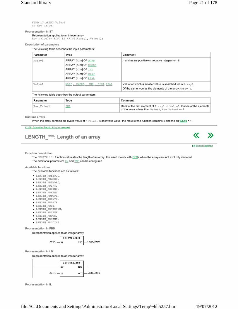
LENGTH_***: Length of an array
Function description
The LENGTH_*** function calculates the length of an array. It is used mainly with DFBs when the arrays are not explicitly declared.
The additional parameters EN and ENO can be configured.
Available functions
The available functions are as follows:
LENGTH_AREBOOL, LENGTH_ARWORD, LENGTH_ARDWORD, LENGTH_ARINT, LENGTH_ARDINT, LENGTH_ARREAL, LENGTH_ARBOOL, LENGTH_ARBYTE, LENGTH_ARDATE, LENGTH_ARDT, LENGTH_ARSTRING, LENGTH_ARTIME, LENGTH_ARTOD, LENGTH_ARUINT, LENGTH_ARUDINT.
Representation in FBD
Representation applied to an integer array:
Representation in LD
Representation applied to an integer array:
Representation in IL
Submit Feedback
Page 21 of 178Standard library
19/07/2012file://C:\Documents and Settings\Administrator\Local Settings\Temp\~hh5257.htm

Representation applied to an integer array: LD Array1 LENGTH_ARINT ST Length_Array1
Representation in ST
Representation: Length_Array1:= LENGTH_ARINT(Array1);
Description of parameters
The following table describes the input parameters:
The following table describes the output parameters:
Parameter Type Comment
Array1 ARRAY [n..m] OF EBOOL
ARRAY [n..m] OF WORD
ARRAY [n..m] OF DWORD
ARRAY [n..m] OF INT
ARRAY [n..m] OF DINT
ARRAY [n..m] OF REAL
ARRAY [n..m] OF BOOL
ARRAY [n..m] OF BYTE
ARRAY [n..m] OF DATE
ARRAY [n..m] OF DT
ARRAY [n..m] OF STRING
ARRAY [n..m] OF TIME
ARRAY [n..m] OF TOD
ARRAY [n..m] OF UINT
ARRAY [n..m] OF UDINT
n and m are positive or negative integers or nil.
Parameter Type Comment
Length_Array1 INT Array length (number of array elements).
© 2011 Schneider Electric. All rights reserved.
MAX_***: Maximum value of array elements
Function description
The MAX_*** function searches for the maximum value of the elements of an array.
The additional parameters EN and ENO can be configured.
Available functions
The available functions are as follows:
MAX_ARWORD, MAX_ARDWORD, MAX_ARINT, MAX_ARDINT, MAX_ARREAL.
Representation in FBD
Representation applied to an integer array:
Representation in LD
Representation applied to an integer array:
Representation in IL
Submit Feedback
Page 22 of 178Standard library
19/07/2012file://C:\Documents and Settings\Administrator\Local Settings\Temp\~hh5257.htm
Representation applied to an integer array: LD Array1 MAX_ARINT ST Max1
Representation in ST
Representation applied to an integer array: Max1:= MAX_ARINT(Array1);
Description of parameters
The following table describes the input parameters:
The following table describes the output parameters:
Runtime errors
When the array contains an invalid value, the result of the function contains ‐1.#INF and the bit %S18 = 1.
Parameter Type Comment
Array1 ARRAY [n..m] OF WORD
ARRAY [n..m] OF DWORD
ARRAY [n..m] OF INT
ARRAY [n..m] OF DINT
ARRAY [n..m] OF REAL
n and m are positive or negative integers or nil.
Parameter Type Comment
Max1 WORD, DWORD, INT , DINT, REAL Maximum value contained in the array. This result is of the same type as the array elements.
© 2011 Schneider Electric. All rights reserved.
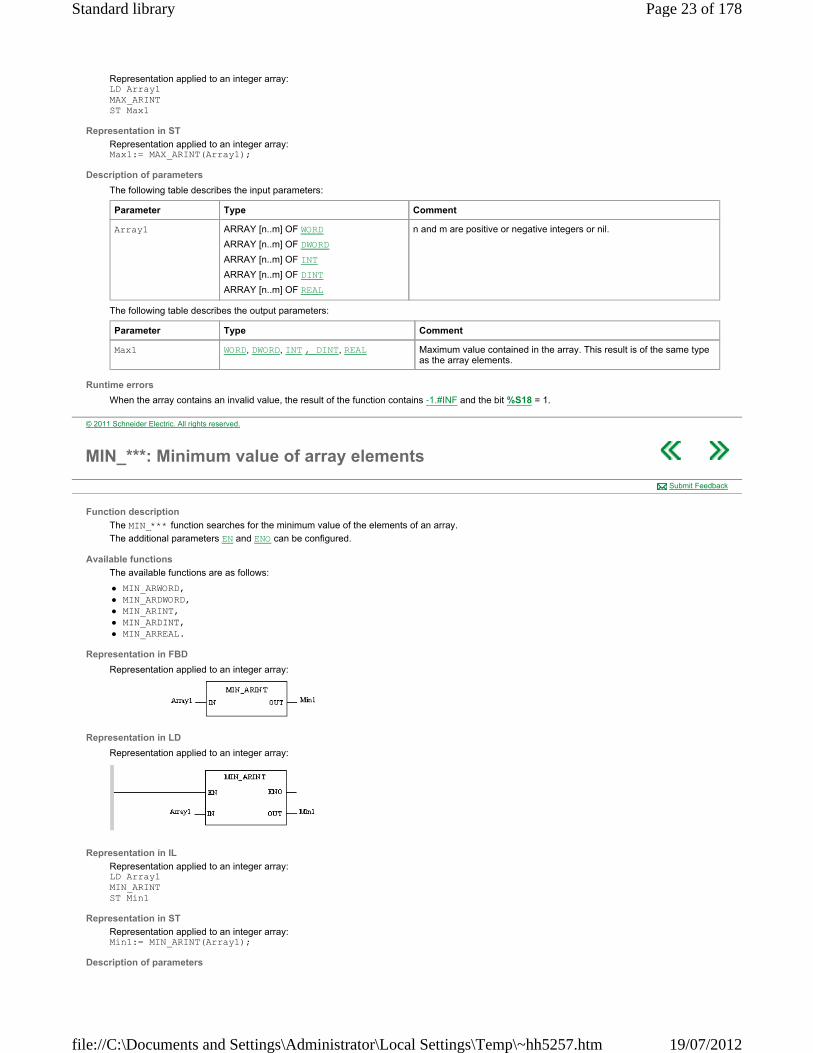
MIN_***: Minimum value of array elements
Function description
The MIN_*** function searches for the minimum value of the elements of an array.
The additional parameters EN and ENO can be configured.
Available functions
The available functions are as follows:
MIN_ARWORD, MIN_ARDWORD, MIN_ARINT, MIN_ARDINT, MIN_ARREAL.
Representation in FBD
Representation applied to an integer array:
Representation in LD
Representation applied to an integer array:
Representation in IL
Representation applied to an integer array: LD Array1 MIN_ARINT ST Min1
Representation in ST
Representation applied to an integer array: Min1:= MIN_ARINT(Array1);
Description of parameters
Submit Feedback
Page 23 of 178Standard library
19/07/2012file://C:\Documents and Settings\Administrator\Local Settings\Temp\~hh5257.htm
The following table describes the input parameters:
The following table describes the output parameters:
Runtime errors
When the array contains an invalid value, the result of the function contains 1.#INF and the bit %S18 = 1.
Parameter Type Comment
Array1 ARRAY [n..m] OF WORD
ARRAY [n..m] OF DWORD
ARRAY [n..m] OF INT
ARRAY [n..m] OF DINT
ARRAY [n..m] OF REAL
n and m are positive or negative integers or nil.
Parameter Type Comment
Min1 WORD , DWORD, DINT, INT, REAL Minimum value contained in the array. This result is of the same type as the array elements.
© 2011 Schneider Electric. All rights reserved.
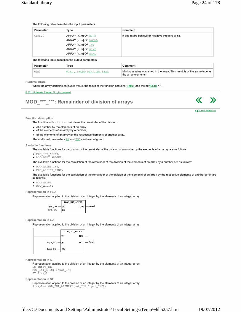
MOD_***_***: Remainder of division of arrays
Function description
The function MOD_***_*** calculates the remainder of the division:
of a number by the elements of an array, of the elements of an array by a number,
of the elements of an array by the respective elements of another array.
The additional parameters EN and ENO can be configured.
Available functions
The available functions for calculation of the remainder of the division of a number by the elements of an array are as follows:
MOD_INT_ARINT, MOD_DINT_ARDINT.
The available functions for the calculation of the remainder of the division of the elements of an array by a number are as follows:
MOD_ARINT_INT, MOD_ARDINT_DINT.
The available functions for the calculation of the remainder of the division of the elements of an array by the respective elements of another array are as follows:
MOD_ARINT, MOD_ARDINT.
Representation in FBD
Representation applied to the division of an integer by the elements of an integer array:
Representation in LD
Representation applied to the division of an integer by the elements of an integer array:
Representation in IL
Representation applied to the division of an integer by the elements of an integer array: LD Input_IN1 MOD_INT_ARINT Input_IN2 ST Array1
Representation in ST
Representation applied to the division of an integer by the elements of an integer array: Array1:= MOD_INT_ARINT(Input_IN1,Input_IN2);
Submit Feedback
Page 24 of 178Standard library
19/07/2012file://C:\Documents and Settings\Administrator\Local Settings\Temp\~hh5257.htm
Description of parameters
The following table describes the input parameters:
The following table describes the output parameters:
Runtime errors
The management of the %S18 system bit is identical to that for operations on words or double words. The remainder of a division by zero is zero and the system bit is set to 1. If an operation between two elements sets the %S18 bit (overflow or division by zero), the result for this operation is incorrect, but the operation on the following elements is carried out correctly.
Parameter Type Comment
Input_ IN1 INT,
DINT,
ARRAY [n..m] OF INT,
ARRAY [n..m] OF DINT
Input_IN1 is either a single or double integer, or an array of single or double integers, n and m are positive or negative integers or nil.
Input_IN2 INT,
DINT,
ARRAY [n..m] OF INT,
ARRAY [n..m] OF DINT
Input_IN2 is either a single or double integer, or an array of single or double integers, n and m are positive or negative integers or nil.
Parameter Type Comment
Array1 ARRAY [n..m] OF INT
ARRAY [n..m] OF DINT
According to the type of Input_IN1 and Input_IN2, each element of Array1 is the remainder of the division:
of a single or double integer Input_IN1 by the corresponding element of the array Input_IN2 or else,
of the elements of the array Input_IN1 by the single or double integer Input_IN2 or else,
of the elements of the array Input_IN1 by the respective elements of the array Input_IN2.
© 2011 Schneider Electric. All rights reserved.
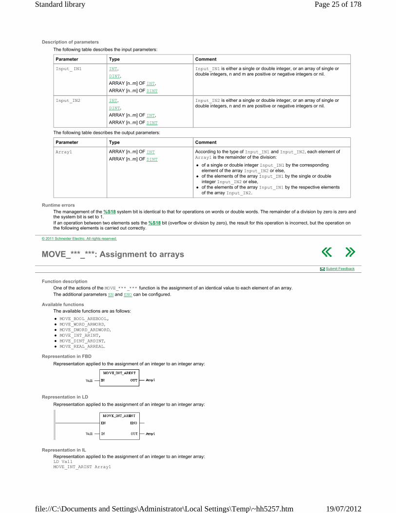
MOVE_***_***: Assignment to arrays
Function description
One of the actions of the MOVE_***_*** function is the assignment of an identical value to each element of an array.
The additional parameters EN and ENO can be configured.
Available functions
The available functions are as follows:
MOVE_BOOL_AREBOOL, MOVE_WORD_ARWORD, MOVE_DWORD_ARDWORD, MOVE_INT_ARINT, MOVE_DINT_ARDINT, MOVE_REAL_ARREAL.
Representation in FBD
Representation applied to the assignment of an integer to an integer array:
Representation in LD
Representation applied to the assignment of an integer to an integer array:
Representation in IL
Representation applied to the assignment of an integer to an integer array: LD Val1 MOVE_INT_ARINT Array1
Submit Feedback
Page 25 of 178Standard library
19/07/2012file://C:\Documents and Settings\Administrator\Local Settings\Temp\~hh5257.htm
Representation in ST
Representation applied to the assignment of an integer to an integer array: MOVE_INT_ARINT(Val1, Array1);
Description of parameters
The following table describes the input parameters:
The following table describes the output parameters:
Parameter Type Comment
Val1 BOOL,
WORD,
DWORD,
INT,
DINT,
REAL.
Val1 contains the value to be assigned to each element of the array Array1.
Of the same type as the elements of the array Array1.
Parameter Type Comment
Array1 ARRAY [n..m] OF EBOOL,
ARRAY [n..m] OF WORD,
ARRAY [n..m] OF DWORD,
ARRAY [n..m] OF INT,
ARRAY [n..m] OF DINT
ARRAY [n..m] OF REAL
n and m are positive or negative integers or nil.
Array1 is an array each element of which is of the value Val1.
© 2011 Schneider Electric. All rights reserved.
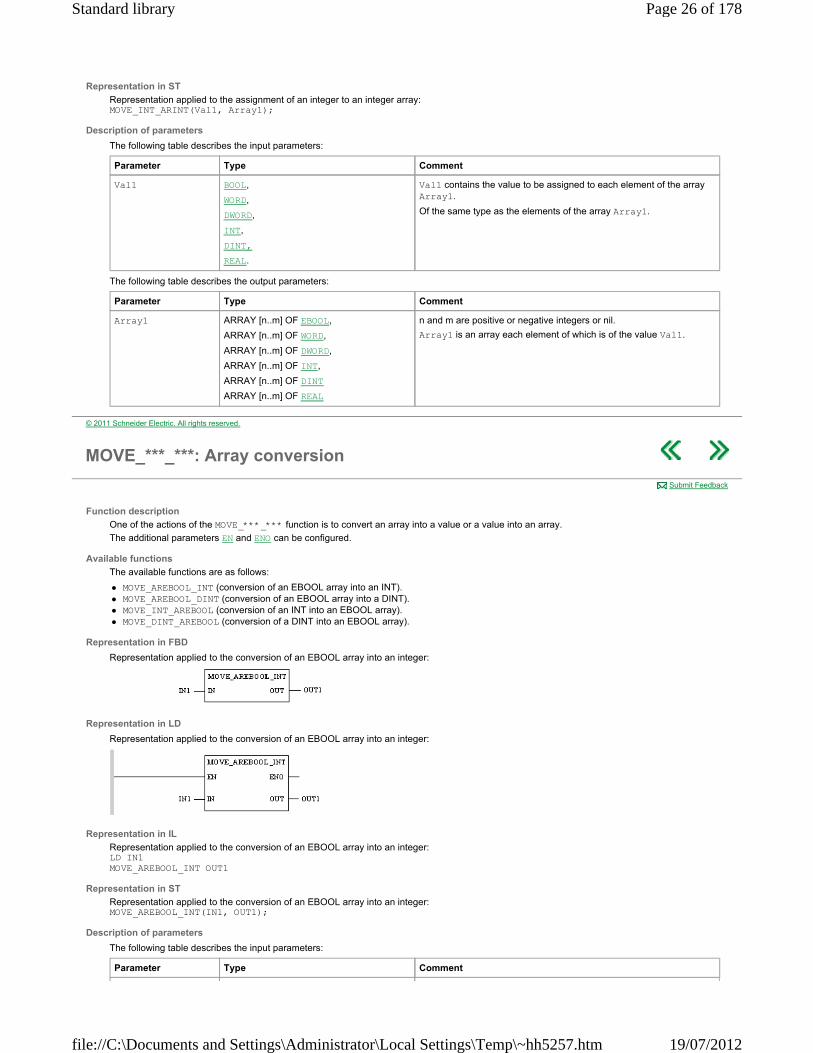
MOVE_***_***: Array conversion
Function description
One of the actions of the MOVE_***_*** function is to convert an array into a value or a value into an array.
The additional parameters EN and ENO can be configured.
Available functions
The available functions are as follows:
MOVE_AREBOOL_INT (conversion of an EBOOL array into an INT). MOVE_AREBOOL_DINT (conversion of an EBOOL array into a DINT). MOVE_INT_AREBOOL (conversion of an INT into an EBOOL array). MOVE_DINT_AREBOOL (conversion of a DINT into an EBOOL array).
Representation in FBD
Representation applied to the conversion of an EBOOL array into an integer:
Representation in LD
Representation applied to the conversion of an EBOOL array into an integer:
Representation in IL
Representation applied to the conversion of an EBOOL array into an integer: LD IN1 MOVE_AREBOOL_INT OUT1
Representation in ST
Representation applied to the conversion of an EBOOL array into an integer: MOVE_AREBOOL_INT(IN1, OUT1);
Description of parameters
The following table describes the input parameters:
Submit Feedback
Parameter Type Comment
Page 26 of 178Standard library
19/07/2012file://C:\Documents and Settings\Administrator\Local Settings\Temp\~hh5257.htm
The following table describes the output parameters:
IN1 INT,
DINT,
ARRAY [n..m] OF EBOOL.
n and m are positive or negative integers or nil.
Parameter Type Comment
OUT1 INT,
DINT,
ARRAY [n..m] OF EBOOL.
When IN1 is an EBOOL array, OUT1 is an INT or DINT containing the elements of IN1.
When IN1 is not an array, OUT1 is a single or double integer, converted from a Boolean array.
© 2011 Schneider Electric. All rights reserved.
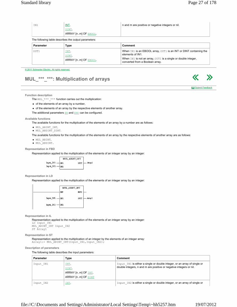
MUL_***_***: Multiplication of arrays
Function description
The MUL_***_*** function carries out the multiplication:
of the elements of an array by a number,
of the elements of an array by the respective elements of another array.
The additional parameters EN and ENO can be configured.
Available functions
The available functions for the multiplication of the elements of an array by a number are as follows:
MUL_ARINT_INT, MUL_ARDINT_DINT.
The available functions for the multiplication of the elements of an array by the respective elements of another array are as follows:
MUL_ARINT, MUL_ARDINT.
Representation in FBD
Representation applied to the multiplication of the elements of an integer array by an integer:
Representation in LD
Representation applied to the multiplication of the elements of an integer array by an integer:
Representation in IL
Representation applied to the multiplication of the elements of an integer array by an integer: LD Input_IN1 MUL_ARINT_INT Input_IN2 ST Array1
Representation in ST
Representation applied to the multiplication of an integer by the elements of an integer array: Array1:= MUL_ARINT_INT(Input_IN1,Input_IN2);
Description of parameters
The following table describes the input parameters:
Submit Feedback
Parameter Type Comment
Input_IN1 INT,
DINT,
ARRAY [n..m] OF INT,
ARRAY [n..m] OF DINT
Input_IN1 is either a single or double integer, or an array of single or double integers, n and m are positive or negative integers or nil.
Input_IN2 INT, Input_IN2 is either a single or double integer, or an array of single or
Page 27 of 178Standard library
19/07/2012file://C:\Documents and Settings\Administrator\Local Settings\Temp\~hh5257.htm

The following table describes the output parameters:
Runtime errors
The management of the %S18 system bit is identical to that for operations on words or double words. If an operation between two elements sets the %S18 bit (overflow or division by zero), the result for this operation is incorrect, but the operation on the following elements is carried out correctly.
DINT,
ARRAY [n..m] OF INT,
ARRAY [n..m] OF DINT
double integers, n and m are positive or negative integers or nil.
Parameter Type Comment
Array1 ARRAY [n..m] OF INT
ARRAY [n..m] OF DINT
According to the type of Input_IN1 and Input_IN2, each element of Array1 is the multiplication:
of a single or double integer Input_IN1 by the corresponding element of the array Input_IN2 or else,
of the elements of the array Input_IN1 by single or double integers Input_IN2 or else,
of the elements of the array Input_IN1 by the respective elements of the array Input_IN2.
© 2011 Schneider Electric. All rights reserved.
NOT_***: Logical negation of arrays
Function description
The NOT_*** function carries out a logical negation (bit to bit) for all the elements of an array. NOTE: The result is always an array. The additional parameters EN and ENO can be configured.
Available functions
The available functions are as follows:
NOT_AREBOOL, NOT_ARWORD, NOT_ARDWORD.
The functions available in the Obsolete library are the following:
NOT_ARINT (logical negation of each element of an INT array). NOT_ARDINT (logical negation of each element of a DINT array).
For example: %M11:3 := NOT_AREBOOL (%M1:3);
when %M1 is 1, %M2 is 0 and %M3 is 1, then %M11 will be 0, %M12 will be 1 and %M13 will be 0.
Representation in FBD
Representation applied to a 16-bit string:
Representation in LD
Representation applied to a 16-bit string:
Representation in IL
Representation applied to a 16-bit string: LD Array1 NOT_ARWORD ST Result_Array
Representation in ST
Representation applied to a 16-bit string: Result_Array:= NOT_ARWORD(Array1);
Description of parameters
The following table describes the input parameters:
Submit Feedback
Page 28 of 178Standard library
19/07/2012file://C:\Documents and Settings\Administrator\Local Settings\Temp\~hh5257.htm
The following table describes the output parameters:
Parameter Type Comment
Array1 ARRAY [n..m] OF EBOOL,
ARRAY [n..m] OF WORD,
ARRAY [n..m] OF DWORD
n and m are positive or negative integers or nil.
Parameter Type Comment
Result_Array ARRAY [n..m] OF EBOOL,
ARRAY [n..m] OF WORD,
ARRAY [n..m] OF DWORD
The elements of Result_Array are the result of the logical NOT (bit to bit) on Array1.
Of the same type as the elements of the array Array 1.
© 2011 Schneider Electric. All rights reserved.
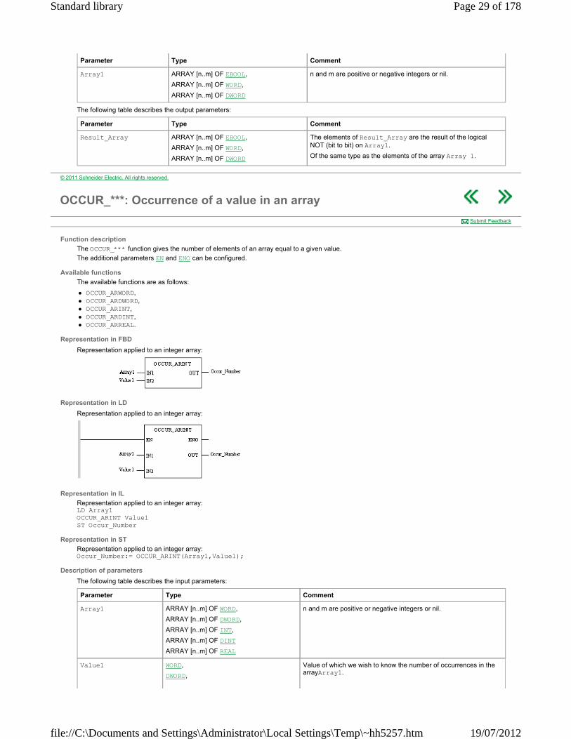
OCCUR_***: Occurrence of a value in an array
Function description
The OCCUR_*** function gives the number of elements of an array equal to a given value.
The additional parameters EN and ENO can be configured.
Available functions
The available functions are as follows:
OCCUR_ARWORD, OCCUR_ARDWORD, OCCUR_ARINT, OCCUR_ARDINT, OCCUR_ARREAL.
Representation in FBD
Representation applied to an integer array:
Representation in LD
Representation applied to an integer array:
Representation in IL
Representation applied to an integer array: LD Array1 OCCUR_ARINT Value1 ST Occur_Number
Representation in ST
Representation applied to an integer array: Occur_Number:= OCCUR_ARINT(Array1,Value1);
Description of parameters
The following table describes the input parameters:
Submit Feedback
Parameter Type Comment
Array1 ARRAY [n..m] OF WORD,
ARRAY [n..m] OF DWORD,
ARRAY [n..m] OF INT,
ARRAY [n..m] OF DINT
ARRAY [n..m] OF REAL
n and m are positive or negative integers or nil.
Value1 WORD,
DWORD,
Value of which we wish to know the number of occurrences in the arrayArray1.
Page 29 of 178Standard library
19/07/2012file://C:\Documents and Settings\Administrator\Local Settings\Temp\~hh5257.htm
The following table describes the output parameters:
INT,
DINT,
REAL
Of the same type as the elements of the array Array 1.
Parameter Type Comment
Occur_Number INT Number of occurrences of Value1 in the array Array1.
© 2011 Schneider Electric. All rights reserved.
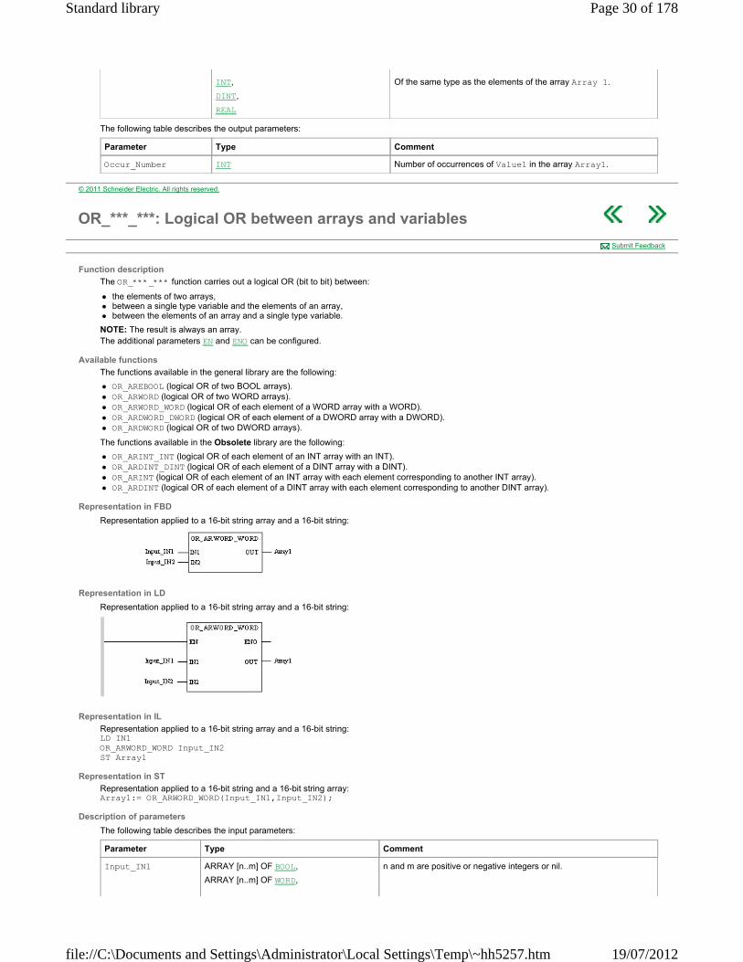
OR_***_***: Logical OR between arrays and variables
Function description
The OR_***_*** function carries out a logical OR (bit to bit) between:
the elements of two arrays, between a single type variable and the elements of an array, between the elements of an array and a single type variable.
NOTE: The result is always an array. The additional parameters EN and ENO can be configured.
Available functions
The functions available in the general library are the following:
OR_AREBOOL (logical OR of two BOOL arrays). OR_ARWORD (logical OR of two WORD arrays). OR_ARWORD_WORD (logical OR of each element of a WORD array with a WORD). OR_ARDWORD_DWORD (logical OR of each element of a DWORD array with a DWORD). OR_ARDWORD (logical OR of two DWORD arrays).
The functions available in the Obsolete library are the following:
OR_ARINT_INT (logical OR of each element of an INT array with an INT). OR_ARDINT_DINT (logical OR of each element of a DINT array with a DINT). OR_ARINT (logical OR of each element of an INT array with each element corresponding to another INT array). OR_ARDINT (logical OR of each element of a DINT array with each element corresponding to another DINT array).
Representation in FBD
Representation applied to a 16-bit string array and a 16-bit string:
Representation in LD
Representation applied to a 16-bit string array and a 16-bit string:
Representation in IL
Representation applied to a 16-bit string array and a 16-bit string: LD IN1 OR_ARWORD_WORD Input_IN2 ST Array1
Representation in ST
Representation applied to a 16-bit string and a 16-bit string array: Array1:= OR_ARWORD_WORD(Input_IN1,Input_IN2);
Description of parameters
The following table describes the input parameters:
Submit Feedback
Parameter Type Comment
Input_IN1 ARRAY [n..m] OF BOOL,
ARRAY [n..m] OF WORD,
n and m are positive or negative integers or nil.
Page 30 of 178Standard library
19/07/2012file://C:\Documents and Settings\Administrator\Local Settings\Temp\~hh5257.htm
The following table describes the output parameters:
ARRAY [n..m] OF DWORD,
ARRAY [n..m] OF INT,
ARRAY [n..m] OF DINT
Input_IN2 WORD,
DWORD,
INT,
DINT,
ARRAY [n..m] OF BOOL,
ARRAY [n..m] OF WORD,
ARRAY [n..m] OF DWORD,
ARRAY [n..m] OF INT,
ARRAY [n..m] OF DINT
n and m are positive or negative integers or nil.
Parameter Type Comment
Array1 ARRAY [n..m] OF BOOL,
ARRAY [n..m] OF WORD,
ARRAY [n..m] OF DWORD,
ARRAY [n..m] OF INT,
ARRAY [n..m] OF DINT
The elements of Array1 are the result of the logical OR (bit to bit) between Input_IN1 and Input_IN2, which can be respectively:
an array and a single variable, an array and an array.
© 2011 Schneider Electric. All rights reserved.
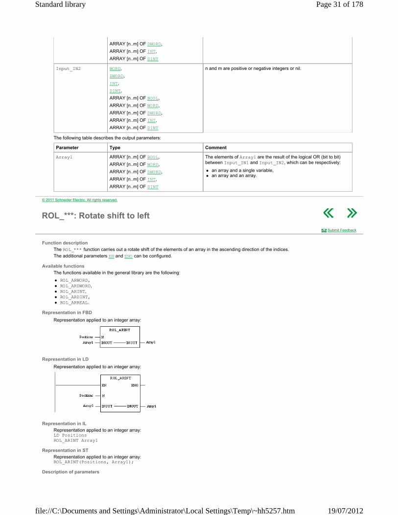
ROL_***: Rotate shift to left
Function description
The ROL_*** function carries out a rotate shift of the elements of an array in the ascending direction of the indices.
The additional parameters EN and ENO can be configured.
Available functions
The functions available in the general library are the following:
ROL_ARWORD, ROL_ARDWORD, ROL_ARINT, ROL_ARDINT, ROL_ARREAL.
Representation in FBD
Representation applied to an integer array:
Representation in LD
Representation applied to an integer array:
Representation in IL
Representation applied to an integer array: LD Positions ROL_ARINT Array1
Representation in ST
Representation applied to an integer array: ROL_ARINT(Positions, Array1);
Description of parameters
Submit Feedback
Page 31 of 178Standard library
19/07/2012file://C:\Documents and Settings\Administrator\Local Settings\Temp\~hh5257.htm

The following table describes the input parameters:
The following table describes the input/output parameters:
Parameter Type Comment
Positions INT Shift value according to the ascending indices of the array.
Example: Positions = 2.
Note: if the value of Positions is negative or nil, no shift is carried out.
Parameter Type Comment
Array1 ARRAY [n..m] OF WORD,
ARRAY [n..m] OF DWORD,
ARRAY [n..m] OF INT,
ARRAY [n..m] OF DINT
ARRAY [n..m] OF REAL
The elements of Array1 are moved a number of positions equal to Positions. The shift is carried out according to the ascending indices.
Example: With a shift register of 2, the element previously situated in first position goes to third (1+2), the second goes to fourth (2+2), ..., the second last goes to first position and the last goes to second position.
© 2011 Schneider Electric. All rights reserved.
ROR_***: Rotate shift to right
Function description
The ROR_*** function carries out a rotate shift of the elements of an array in the descending direction of the indices.
The additional parameters EN and ENO can be configured.
Available functions
The functions available in the general library are the following:
ROR_ARWORD, ROR_ARDWORD, ROR_ARINT, ROR_ARDINT. ROR_ARREAL.
Representation in FBD
Representation applied to an integer array:
Representation in LD
Representation applied to an integer array:
Representation in IL
Representation applied to an integer array: LD Positions ROR_ARINT Array1
Representation in ST
Representation applied to an integer array: ROR_ARINT(Positions, Array1);
Description of parameters
The following table describes the input parameters:
Submit Feedback
Parameter Type Comment
Positions INT Shift value according to the descending indices of the array.
Example: Positions = 2.
Note: if the value of Positions is negative or nil, no shift is carried out.
Page 32 of 178Standard library
19/07/2012file://C:\Documents and Settings\Administrator\Local Settings\Temp\~hh5257.htm

The following table describes the input/output parameters:
Parameter Type Comment
Array1 ARRAY [n..m] OF WORD,
ARRAY [n..m] OF DWORD,
ARRAY [n..m] OF INT,
ARRAY [n..m] OF DINT
ARRAY [n..m] OF REAL
The elements of Array1 are moved a number of positions equal to Positions. The shift is carried out according to the descending indicators.
Example: With a shift register of 2, the element previously situated in first position goes to second last, the second goes to last, the third goes to first (3-2), the fourth to second (4 -2), etc.
© 2011 Schneider Electric. All rights reserved.
SORT_***: Ascending or descending sort
Function description
The SORT_*** function sorts an array in ascending or descending order and arranges the sorted elements in this same array.
The additional parameters EN and ENO can be configured.
Available functions
The available functions are as follows:
SORT_ARWORD, SORT_ARDWORD, SORT_ARINT, SORT_ARDINT, SORT_ARREAL.
Representation in FBD
Representation applied to an integer array:
Representation in LD
Representation applied to an integer array:
Representation in IL
Representation applied to an integer array: LD Direction SORT_ARINT Array1
Representation in ST
Representation applied to an integer array: SORT_ARINT(Direction, Array1);
Description of parameters
The following table describes the input parameters:
The following table describes the input/output parameters:
Submit Feedback
Parameter Type Comment
Direction INT Direction of sort to be carried out:
Direction ≥ 0: ascending sort, Direction < 0: descending sort.
Page 33 of 178Standard library
19/07/2012file://C:\Documents and Settings\Administrator\Local Settings\Temp\~hh5257.htm
Parameter Type Comment
Array1 ARRAY [n..m] OF WORD,
ARRAY [n..m] OF DWORD,
ARRAY [n..m] OF INT,
ARRAY [n..m] OF DINT
ARRAY [n..m] OF REAL
Array sorted in the direction specified in Direction, n and m are positive or negative integers, or nil.
© 2011 Schneider Electric. All rights reserved.
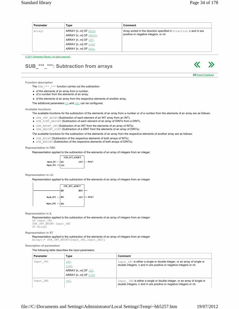
SUB_***_***: Subtraction from arrays
Function description
The SUB_***_*** function carries out the subtraction:
of the elements of an array from a number, of a number from the elements of an array,
of the elements of an array from the respective elements of another array.
The additional parameters EN and ENO can be configured.
Available functions
The available functions for the subtraction of the elements of an array from a number or of a number from the elements of an array are as follows:
SUB_INT_ARINT (Subtraction of each element of an INT array from an INT). SUB_DINT_ARDINT (Subtraction of each element of an array of DINTs from a DINT).
SUB_ARINT_INT (Subtraction of an INT from the elements of an array of INTs). SUB_ARDINT_DINT (Subtraction of a DINT from the elements of an array of DINTs).
The available functions for the subtraction of the elements of an array from the respective elements of another array are as follows:
SUB_ARINT (Subtraction of the respective elements of both arrays of INTs). SUB_ARDINT (Subtraction of the respective elements of both arrays of DINTs).
Representation in FBD
Representation applied to the subtraction of the elements of an array of integers from an integer:
Representation in LD
Representation applied to the subtraction of the elements of an array of integers from an integer:
Representation in IL
Representation applied to the subtraction of the elements of an array of integers from an integer: LD Input_IN1 SUB_INT_ARINT Input_IN2 ST Array1
Representation in ST
Representation applied to the subtraction of the elements of an array of integers from an integer: Array1:= SUB_INT_ARINT(Input_IN1,Input_IN2);
Description of parameters
The following table describes the input parameters:
Submit Feedback
Parameter Type Comment
Input_IN1 INT,
DINT,
ARRAY [n..m] OF INT,
ARRAY [n..m] OF DINT
Input_IN1 is either a single or double integer, or an array of single or double integers, n and m are positive or negative integers or nil.
Input_IN2 INT, Input_ IN2 is either a single or double integer, or an array of single or double integers, n and m are positive or negative integers or nil.
Page 34 of 178Standard library
19/07/2012file://C:\Documents and Settings\Administrator\Local Settings\Temp\~hh5257.htm
The following table describes the output parameters:
Runtime errors
The management of the %S18 system bit is identical to that for operations on words or double words. If an operation between two elements sets the %S18 bit (overflow or division by zero), the result for this operation is incorrect, but the operation on the following elements is carried out correctly.
DINT,
ARRAY [n..m] OF INT,
ARRAY [n..m] OF DINT
Parameter Type Comment
Array1 ARRAY [n..m] OF INT
ARRAY [n..m] OF DINT
According to the type of Input_IN1 and Input_IN2, each element of Array1 is the subtraction:
from a single or double integer Input_IN1 of the corresponding element of the array Input_IN2 or else,
from the elements of the array Input_IN1 of the single or double integer Input_IN2 or else,
from the elements of the array Input_IN1 of the respective elements of the array Input_IN2.
© 2011 Schneider Electric. All rights reserved.
SUM_***: Sum of array elements
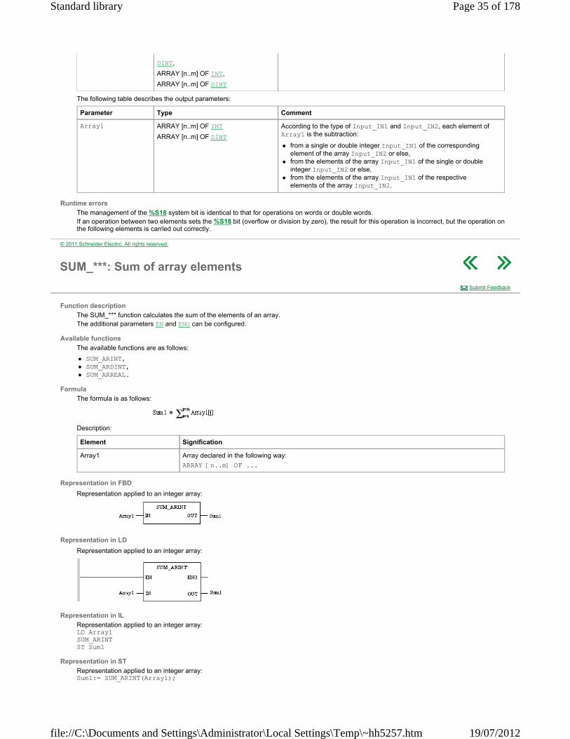
Function description
The SUM_*** function calculates the sum of the elements of an array. The additional parameters EN and ENO can be configured.
Available functions
The available functions are as follows:
SUM_ARINT, SUM_ARDINT, SUM_ARREAL.
Formula
The formula is as follows:
Description:
Representation in FBD
Representation applied to an integer array:
Representation in LD
Representation applied to an integer array:
Representation in IL
Representation applied to an integer array: LD Array1 SUM_ARINT ST Sum1
Representation in ST
Representation applied to an integer array: Sum1:= SUM_ARINT(Array1);
Submit Feedback
Element Signification
Array1 Array declared in the following way:
ARRAY [n..m] OF ...
Page 35 of 178Standard library
19/07/2012file://C:\Documents and Settings\Administrator\Local Settings\Temp\~hh5257.htm
Description of parameters
The following table describes the input parameters:
The following table describes the output parameters:
Runtime errors
When the array contains an invalid value, the sum of its elements contains 0.0 and the bit %S18 = 1. When the sum of elements is greater than the maximum authorized value, its value becomes 1.#INF and the bit %S18 = 1
Parameter Type Comment
Array1 ARRAY [n..m] OF INT
ARRAY [n..m] OF DINT
ARRAY [n..m] OF REAL
Double or single integer arrays or arrays of reals, n and m are positive or negative integers, or nil.
Parameter Type Comment
Sum1 INT, DINT, REAL Sum of array elements assigned to input. The sum is of the same type as the array elements.
© 2011 Schneider Electric. All rights reserved.
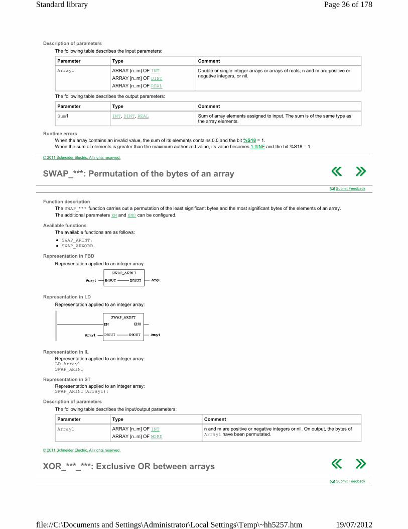
SWAP_***: Permutation of the bytes of an array
Function description
The SWAP_*** function carries out a permutation of the least significant bytes and the most significant bytes of the elements of an array.
The additional parameters EN and ENO can be configured.
Available functions
The available functions are as follows:
SWAP_ARINT, SWAP_ARWORD.
Representation in FBD
Representation applied to an integer array:
Representation in LD
Representation applied to an integer array:
Representation in IL
Representation applied to an integer array: LD Array1 SWAP_ARINT
Representation in ST
Representation applied to an integer array: SWAP_ARINT(Array1);
Description of parameters
The following table describes the input/output parameters:
Submit Feedback
Parameter Type Comment
Array1 ARRAY [n..m] OF INT
ARRAY [n..m] OF WORD
n and m are positive or negative integers or nil. On output, the bytes of Array1 have been permutated.
© 2011 Schneider Electric. All rights reserved.
XOR_***_***: Exclusive OR between arrays
Submit Feedback
Page 36 of 178Standard library
19/07/2012file://C:\Documents and Settings\Administrator\Local Settings\Temp\~hh5257.htm
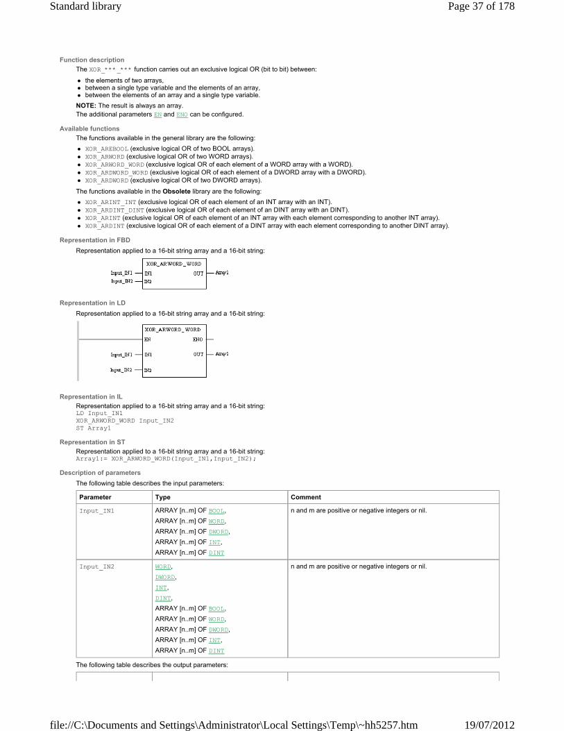
Function description
The XOR_***_*** function carries out an exclusive logical OR (bit to bit) between:
the elements of two arrays, between a single type variable and the elements of an array, between the elements of an array and a single type variable.
NOTE: The result is always an array. The additional parameters EN and ENO can be configured.
Available functions
The functions available in the general library are the following:
XOR_AREBOOL (exclusive logical OR of two BOOL arrays). XOR_ARWORD (exclusive logical OR of two WORD arrays). XOR_ARWORD_WORD (exclusive logical OR of each element of a WORD array with a WORD). XOR_ARDWORD_WORD (exclusive logical OR of each element of a DWORD array with a DWORD). XOR_ARDWORD (exclusive logical OR of two DWORD arrays).
The functions available in the Obsolete library are the following:
XOR_ARINT_INT (exclusive logical OR of each element of an INT array with an INT). XOR_ARDINT_DINT (exclusive logical OR of each element of an DINT array with an DINT). XOR_ARINT (exclusive logical OR of each element of an INT array with each element corresponding to another INT array). XOR_ARDINT (exclusive logical OR of each element of a DINT array with each element corresponding to another DINT array).
Representation in FBD
Representation applied to a 16-bit string array and a 16-bit string:
Representation in LD
Representation applied to a 16-bit string array and a 16-bit string:
Representation in IL
Representation applied to a 16-bit string array and a 16-bit string: LD Input_IN1 XOR_ARWORD_WORD Input_IN2 ST Array1
Representation in ST
Representation applied to a 16-bit string array and a 16-bit string: Array1:= XOR_ARWORD_WORD(Input_IN1,Input_IN2);
Description of parameters
The following table describes the input parameters:
The following table describes the output parameters:
Parameter Type Comment
Input_IN1 ARRAY [n..m] OF BOOL,
ARRAY [n..m] OF WORD,
ARRAY [n..m] OF DWORD,
ARRAY [n..m] OF INT,
ARRAY [n..m] OF DINT
n and m are positive or negative integers or nil.
Input_IN2 WORD,
DWORD,
INT,
DINT,
ARRAY [n..m] OF BOOL,
ARRAY [n..m] OF WORD,
ARRAY [n..m] OF DWORD,
ARRAY [n..m] OF INT,
ARRAY [n..m] OF DINT
n and m are positive or negative integers or nil.
Page 37 of 178Standard library
19/07/2012file://C:\Documents and Settings\Administrator\Local Settings\Temp\~hh5257.htm

Parameter Type Comment
Array1 ARRAY [n..m] OF BOOL,
ARRAY [n..m] OF WORD,
ARRAY [n..m] OF DWORD,
ARRAY [n..m] OF INT,
ARRAY [n..m] OF DINT
The elements of Array1 are the result of the exclusive logical OR (bit to bit) between Input_ IN1 and Input_IN2, which can be respectively:
an array and a single variable, a single variable and an array, an array and an array.
© 2011 Schneider Electric. All rights reserved.
CLC_INT
Overview
This section describes the elementary functions and elementary function blocks of the CLC_INT family.
What's in this Part?
This part contains the following chapters:
Introduction to integer regulation functions PID_INT: PID controller PWM_INT: Pulse width modulation of a numerical value SERVO_INT: Servo drive function
© 2011 Schneider Electric. All rights reserved.
Introduction to integer regulation functions
Subject of this Chapter
This chapter provides the basic notions necessary for the use and implementation of the following integer regulation functions:
PID_INT, PWM_INT, SERVO_INT.
What's in this Chapter?
This chapter contains the following topics:
General Introduction Principal of the regulation loop Development methodology for a regulation application Programming a regulation function Behavior of functions in operating modes
© 2011 Schneider Electric. All rights reserved.
General Introduction
General
The regulation functions are the standard elements of the language. They are used to program regulation loops. These functions are particularly adapted to:
meeting the requirements of sequential processes which need auxiliary regulation functions (e.g.: plastic film packaging machines, finishing treatment machines, presses etc.)
meeting the requirements of simple regulation processes (e.g.: metal furnaces, ceramic furnaces, small refrigerating units etc.), meeting the specific requirements of mechanical regulation or feedback control where sampling time is critical (e.g.: torque regulation, speed
regulation).
NOTE: There is no limit on the number of PID_INT functions that are available in an application. In practice, it is the maximum number of input and output modules which are accepted by the PLC that limits the number of loops.
Available functions
The basic regulation functions are the following:
the PID_INT function to execute a mixed PID_INT correction (serial – parallel), the PWM_INT function to execute the modulation adjustment period on the discrete outputs, the SERVO_INT function to execute the motor command adaptations.
Submit Feedback
© 2011 Schneider Electric. All rights reserved.
Page 38 of 178Standard library
19/07/2012file://C:\Documents and Settings\Administrator\Local Settings\Temp\~hh5257.htm

Principal of the regulation loop
At a Glance
A regulation loop has three distinct operating phases:
the acquisition of data:
measurements from the process’ sensors (analog, encoders), setpoint(s) generally from PLC internal variables or from data from the operator terminal.
execution of the PID regulation algorithm, the sending of commands adapted to the characteristics of the actuators to be driven via the discrete or analog outputs.
The PID algorithm generates the command signal from:
the measurement sampled by the input nodule, the setpoint value fixed by either the operator or the program, the values of the different corrector parameters.
The signal from the corrector is either directly handled by an analog output card of the PLC linked to the actuator, or handled via the PWM or SERVO adjustments depending on the types of actuator to be driven on a discrete output card of the PLC.
Illustration
The following diagram schematizes the principal of a regulation loop.
Submit Feedback
© 2011 Schneider Electric. All rights reserved.
Development methodology for a regulation application
Flow diagram
The following diagram shows the links between tasks to be carried out during the creation and debugging of a regulation application (the order shown here is for information purposes only).
Submit Feedback
Page 39 of 178Standard library
19/07/2012file://C:\Documents and Settings\Administrator\Local Settings\Temp\~hh5257.htm

© 2011 Schneider Electric. All rights reserved.
Programming a regulation function
Programming rules
The regulation function parameters must all be entered. The functions use 3 kinds of parameters:
read only parameters, considered at the beginning of the function’s execution, write only parameters, positioned at the conclusion of the function’s execution, the read and write parameters, whose contents are considered at the beginning of the function’s execution, are then updated by the results of
the function.
NOTE: The regulation functions must be programmed in a periodic task (periodic MAST or FAST). They must not be conditioned.
Parametering
The word type input parameters are analog dimensions expressed on the scale [0, +10000] and can be directly connected to measurement sensors via the %IWr.m.c words of the analog inputs. The bit type output parameters can be used to control discrete actuators and can be directly connected to the %Qr.m.c. type variables. In the same way, the word type output parameters can be used to control analog actuators on the scale [0, +10000] and can be directly assigned to %QWr.m.c type variables. The ARRAY [0..n] OF INT or %MWi:L integer table type parameters contain the user parameters and data necessary to the internal operation of the function. If the length of a table is insufficient, the function is not executed. NOTE: In order to keep the adjustment parameters of the regulation on cold start function, it is necessary to delete the %MWi reset to zero option (in the processor’s configuration screen)
Submit Feedback
© 2011 Schneider Electric. All rights reserved.
Behavior of functions in operating modes
Introduction
This paragraph describes the behavior of the functions in different start-up scenarios:
cold start (new application, change of cartridge…), warm restart (power return without changing the application context), first execution after adding a function via modification in connected mode.
Cold start
This type of start occurs for a new application or a change of cartridge On a cold start, the PLC can start automatically in RUN (according to the application’s configuration). The function correctors have the following security behavior: manual mode, outputs at 0. In addition, this supports the switching of the PLC into RUN mode without carrying out the PID adjustment, then its debugging with the operator terminal (the adjustment can only be performed in RUN).
Warm restart
Submit Feedback
Page 40 of 178Standard library
19/07/2012file://C:\Documents and Settings\Administrator\Local Settings\Temp\~hh5257.htm
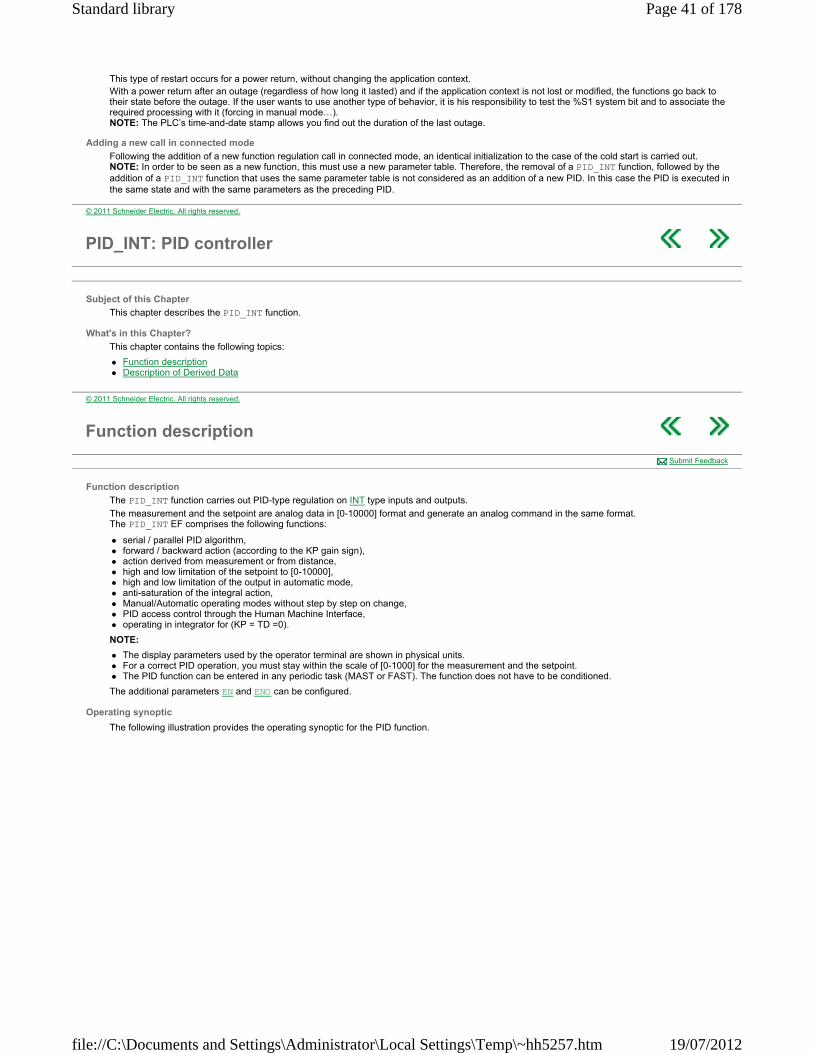
This type of restart occurs for a power return, without changing the application context. With a power return after an outage (regardless of how long it lasted) and if the application context is not lost or modified, the functions go back to their state before the outage. If the user wants to use another type of behavior, it is his responsibility to test the %S1 system bit and to associate the required processing with it (forcing in manual mode…). NOTE: The PLC’s time-and-date stamp allows you find out the duration of the last outage.
Adding a new call in connected mode
Following the addition of a new function regulation call in connected mode, an identical initialization to the case of the cold start is carried out. NOTE: In order to be seen as a new function, this must use a new parameter table. Therefore, the removal of a PID_INT function, followed by the addition of a PID_INT function that uses the same parameter table is not considered as an addition of a new PID. In this case the PID is executed in the same state and with the same parameters as the preceding PID.
© 2011 Schneider Electric. All rights reserved.
PID_INT: PID controller
Subject of this Chapter
This chapter describes the PID_INT function.
What's in this Chapter?
This chapter contains the following topics:
Function description Description of Derived Data
© 2011 Schneider Electric. All rights reserved.
Function description
Function description
The PID_INT function carries out PID-type regulation on INT type inputs and outputs.
The measurement and the setpoint are analog data in [0-10000] format and generate an analog command in the same format. The PID_INT EF comprises the following functions:
serial / parallel PID algorithm, forward / backward action (according to the KP gain sign), action derived from measurement or from distance, high and low limitation of the setpoint to [0-10000], high and low limitation of the output in automatic mode, anti-saturation of the integral action, Manual/Automatic operating modes without step by step on change, PID access control through the Human Machine Interface, operating in integrator for (KP = TD =0).
NOTE:
The display parameters used by the operator terminal are shown in physical units. For a correct PID operation, you must stay within the scale of [0-1000] for the measurement and the setpoint. The PID function can be entered in any periodic task (MAST or FAST). The function does not have to be conditioned.
The additional parameters EN and ENO can be configured.
Operating synoptic
The following illustration provides the operating synoptic for the PID function.
Submit Feedback
Page 41 of 178Standard library
19/07/2012file://C:\Documents and Settings\Administrator\Local Settings\Temp\~hh5257.htm
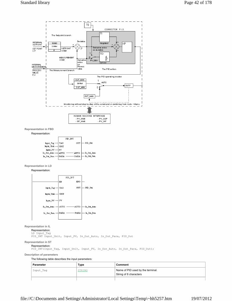
Representation in FBD
Representation:
Representation in LD
Representation:
Representation in IL
Representation: LD Input_Tag PID_INT Input_Unit, Input_PV, In_Out_Auto, In_Out_Para, PID_Out
Representation in ST
Representation: PID_INT(Input_Tag, Input_Unit, Input_PV, In_Out_Auto, In_Out_Para, PID_Out);
Description of parameters
The following table describes the input parameters:
Parameter Type Comment
Input_Tag STRING Name of PID used by the terminal.
String of 8 characters
Page 42 of 178Standard library
19/07/2012file://C:\Documents and Settings\Administrator\Local Settings\Temp\~hh5257.htm
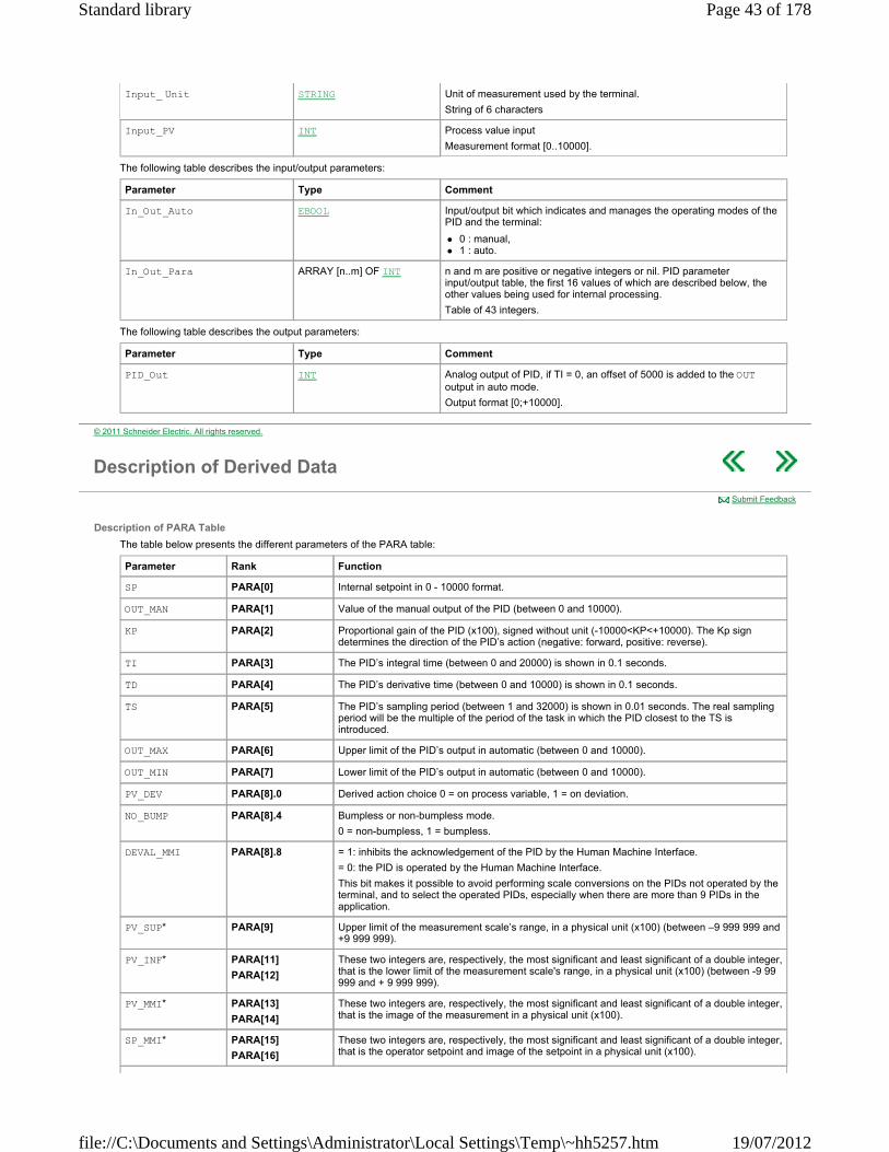
The following table describes the input/output parameters:
The following table describes the output parameters:
Input_ Unit STRING Unit of measurement used by the terminal.
String of 6 characters
Input_PV INT Process value input
Measurement format [0..10000].
Parameter Type Comment
In_Out_Auto EBOOL Input/output bit which indicates and manages the operating modes of the PID and the terminal:
0 : manual, 1 : auto.
In_Out_Para ARRAY [n..m] OF INT n and m are positive or negative integers or nil. PID parameter input/output table, the first 16 values of which are described below, the other values being used for internal processing.
Table of 43 integers.
Parameter Type Comment
PID_Out INT Analog output of PID, if TI = 0, an offset of 5000 is added to the OUT output in auto mode.
Output format [0;+10000].
© 2011 Schneider Electric. All rights reserved.
Description of Derived Data
Description of PARA Table
The table below presents the different parameters of the PARA table:
Submit Feedback
Parameter Rank Function
SP PARA[0] Internal setpoint in 0 - 10000 format.
OUT_MAN PARA[1] Value of the manual output of the PID (between 0 and 10000).
KP PARA[2] Proportional gain of the PID (x100), signed without unit (-10000<KP<+10000). The Kp sign determines the direction of the PID’s action (negative: forward, positive: reverse).
TI PARA[3] The PID’s integral time (between 0 and 20000) is shown in 0.1 seconds.
TD PARA[4] The PID’s derivative time (between 0 and 10000) is shown in 0.1 seconds.
TS PARA[5] The PID’s sampling period (between 1 and 32000) is shown in 0.01 seconds. The real sampling period will be the multiple of the period of the task in which the PID closest to the TS is introduced.
OUT_MAX PARA[6] Upper limit of the PID’s output in automatic (between 0 and 10000).
OUT_MIN PARA[7] Lower limit of the PID’s output in automatic (between 0 and 10000).
PV_DEV PARA[8].0 Derived action choice 0 = on process variable, 1 = on deviation.
NO_BUMP PARA[8].4 Bumpless or non-bumpless mode.
0 = non-bumpless, 1 = bumpless.
DEVAL_MMI PARA[8].8 = 1: inhibits the acknowledgement of the PID by the Human Machine Interface.
= 0: the PID is operated by the Human Machine Interface.
This bit makes it possible to avoid performing scale conversions on the PIDs not operated by the terminal, and to select the operated PIDs, especially when there are more than 9 PIDs in the application.
PV_SUP* PARA[9] Upper limit of the measurement scale’s range, in a physical unit (x100) (between –9 999 999 and +9 999 999).
PV_INF* PARA[11]
PARA[12]
These two integers are, respectively, the most significant and least significant of a double integer, that is the lower limit of the measurement scale's range, in a physical unit (x100) (between -9 99 999 and + 9 999 999).
PV_MMI* PARA[13]
PARA[14]
These two integers are, respectively, the most significant and least significant of a double integer, that is the image of the measurement in a physical unit (x100).
SP_MMI* PARA[15]
PARA[16]
These two integers are, respectively, the most significant and least significant of a double integer, that is the operator setpoint and image of the setpoint in a physical unit (x100).
Page 43 of 178Standard library
19/07/2012file://C:\Documents and Settings\Administrator\Local Settings\Temp\~hh5257.htm

NOTE: The values used by the terminal are multiplied by 100 in order to support a display with 2 figures after the decimal point on the terminal (the terminal does not use floating point format but supports a fixed comma format).
Rules
There is no internal setpoint alignment on the measurement in manual mode. The settings on the scale only take place on modification of one of the setpoints (SP or DOP_SP).
The algorithm without the integral action (TI = 0) carries out the following operation:
The algorithm with the integral action (TI <0) carries out the following operation:
On a cold start, the PID starts off again in manual, with the output at 0. To impose the automatic mode or a manual output that is not at 0 after a cold start, you will have to program the initialization sequence after the PID call.
* Value used by the operator terminal.
WARNING UNEXPECTED APPLICATION BEHAVIOR
Do not modify parameters used by the PID’s internal management by the application.
Failure to follow these instructions can result in death, serious injury, or equipment damage.
For Then the output With
OUT = KP [ t+ Dt] / 100 + 5000 Dt = derived action
For Then the output With
OUT = KP [ t+(TS/10.TI). t+ Dt]/100 OUT = OUT + OUT Dt = derived action
© 2011 Schneider Electric. All rights reserved.
PWM_INT: Pulse width modulation of a numerical value
Function description
The PWM_INT function carries out pulse width regulation on a Discrete output. It is a function that formats a PID output.
The pulse width depends on the PID’s output (The PWM function’s INP input) and the modulation period. NOTE: the PWM_INT function can be entered in any periodic task (MAST or FAST). The function does not have to be conditioned.
The additional parameters EN and ENO can be configured.
Operating synoptic
The following diagram shows the operating synoptic of the PWM function:
Representation in FBD
Representation:
Representation in LD
Representation:
Submit Feedback
Page 44 of 178Standard library
19/07/2012file://C:\Documents and Settings\Administrator\Local Settings\Temp\~hh5257.htm

Representation in IL
Representation: LD Input_INP PWM_INT In_Out_Para, PW_O_Out
Representation in ST
Representation: PWM_INT(Input_INP, In_Out_Para, PW_O_Out);
Description of parameters
The following table describes the input parameters:
The following table describes the input/output parameters:
The following table describes the output parameters:
Pulse widths
To each Top of the T_MOD modulation period, the activation period in 10-3 seconds of the PW_O_Out (PW_O) output is calculated according to the following formula:
State 1 of the gap (shown in 10-2 seconds) = INP * T_MOD / 1000
The following timing diagram illustrates this formula:
Practical rules
T_MOD = TS (where TS is the sampling period of the upstream PID).
The period of the current task (expressed in 10-3 seconds) is equal to:
(Required resolution)* 10 * T_MOD.
The PID is in the MAST task, the MAST’s period is 50*10-3 s, TS = 500*10-2 s and the required resolution is 1/50 (a T_MOD period must contain at least 50 periods of the current task). Let T_MOD = TS = 500.
The period of the task in which the PWM is introduced must be less than
500 * 10 / 50 =100 10-3 s.
The PWM function can therefore be programmed in the MAST task. The resolution will be 1/100.
Parameter Type Comment
Input_INP INT Analog value to be modulated in pulse width (format [0 – 10000]).
Parameter Type Comment
In_Out_Para ARRAY [n..m] OF INT n and m are positive or negative integers or nil.
Input/output table of function parameters. The first word corresponds to the parameter T_MOD.
Modulation period expressed in 1/100ths of seconds (between 0 and 32767). T_MOD must be greater than or equal to the current task period, and is adjusted by the system to be an integer that is a multiple of this.
The following integers are used internally by the function and must never be modified by the application.
Table of 5 integers.
Parameter Type Comment
PW_O _Out EBOOL Analog output of PID, if TI = 0, an offset of 5000 is added to the OUT output in auto mode.
© 2011 Schneider Electric. All rights reserved.
SERVO_INT: Servo drive function
Submit Feedback
Page 45 of 178Standard library
19/07/2012file://C:\Documents and Settings\Administrator\Local Settings\Temp\~hh5257.htm

Function description
The SERVO_INT function carries out a regulation with a motor-type actuator driven by two Discrete outputs (UP and DOWN). NOTE:
A SERVO_INT function can be entered in any periodic task (MAST or FAST). The function does not have to be conditioned. It must be connected in tandem with the analog output of a PID. It cannot be used alone.
When there is a copy of a position, the valve’s position is locked via the Input_Inp (setpoint) and Input_Pot (position measurement) inputs.
When the copy does not physically exist, the algorithm no longer uses the PID’s absolute output but the output’s variation. The Out_Up output (or Out_Down, according to the variation sign) is set to 1 for a length of time proportional to the actuator opening time and to the variation of the value. Also, the notion of minimum pulse time is introduced. The additional parameters EN and ENO can be configured.
Representation in FBD
Representation:
Representation in LD
Representation:
Representation in IL
Representation: LD Input_Inp SERVO_INT Input_Pot, In_Out_Pid, In_Out_Para, Out_Up, Out_Down
Representation in ST
Representation: SERVO_INT(Input_Inp, Input_Pot, In_Out_Pid, In_Out_Para, Out_Up, Out_Down);
Description of parameters
The following table describes the input parameters:
The following table describes the input/output parameters:
Parameter Type Comment
Input_Inp INT Position setpoint ([0 -10000] format) that has to be connected to the PID output.
Input_Pot INT Position copy, ([0 -10000] format)
0 : closed valve; 10000: open valve.
If the copy does not exist, Input_ POT must be initialized at -10000. This particular value indicates "no copy".
Parameter Type Comment
In_Out_Pid ARRAY [n..m] OF INT n and m are positive or negative integers or nil.
Parameter table of upstream PID, used if there are no copy words for the synchronization with the upstream PID.
Table of 43 integers.
In_Out_Para ARRAY [n..m] OF INT n and m are positive or negative integers or nil.
The first three parameters are used if the copy does not exist (Input_POT = -10000):
In_Out_PARA[0] also called T_MOTOR is the valve opening time
expressed in 10-2 s. In_Out_ PARA[1] also called T_MINI is the minimum pulse
expressed in 10-2 s.
In_Out_PARA[2] also called HYST is the hysteresis value in [0‐10000] format.
Page 46 of 178Standard library
19/07/2012file://C:\Documents and Settings\Administrator\Local Settings\Temp\~hh5257.htm

The following table describes the output parameters:
Principle of operating with a position copy
The SERVO_INT function locks the motor’s position according to a setpoint of the Input_Inp (INP) position from a PID’s output in [0 ‐ 10000] format, and to a Input_Pot (POT) position measurement.
The locking algorithm is a relay with hysteresis.
In this case, the PID, T_MOTOR and T_MINI parameters are not used.
Principle of operating without a position copy (POT= ‐10000)
In this case, the SERVO_INT function is synchronized with the upstream PID by using the PID parameter table passed on to the SERVO_INT function as a parameter. The algorithm receives in input the PID’s variation output and converts it into pulse period, according to the following formula:
T_IMP (expressed in 10-3 s) = OUT x T_MOTOR / 1000
The acquired period is added to the remaining period of the preceding cycles: In fact, what is not "consumed" in a cycle is memorized for the following cycles. This ensures correct operation, especially where there are sudden variations in the command (e.g.: PID setpoint scale division) and in manual mode.
Example
The example below is in Ladder language:
Note 1: The SERVO_INT function does not manage the position limits. These must be managed by the application. If a limit is detected, you must force the corresponding output to 0 (UP for the high limit, DOWN for the low limit).
Example: in Ladder language
Note: the other parameters that are used by the function’s internal management must never be modified by the application. All the parameters are obligatory, regardless of the operating mode.
Table of 10 integers.
Parameter Type Comment
Out_Up EBOOL Output signal for the motor’s Out_Up operating direction.
Out_Down EBOOL Output signal for the motor’s Out_Down operating direction.
Label Description
1 The PID output variation is +20 % (T_MOTOR pulse =25 s for a 100 % variation). In this case, the pulse affects the UP output for a period of 5 s.
2 The PID variation is +2 %, which would correspond to a pulse of 0.5 s. This pulse is less than T_MINI (=1 s.), and it does not affect the outputs.
3 A second variation of +2 % appears and the function adds this variation to the previous one (which corresponded to a variation less than the minimal value), which corresponds to a positive global variation of +4 %, and therefore to a pulse of 1 s on the UP output.
4 A variation of -24 % appears and the activated pulse is therefore of 6 s on the DOWN output.
5 Before the following second has elapsed, another variation of +22 % brings the system back to a global variation of 2 % < the variation of T_MINI (4 %). The function finishes carrying out the minimal pulse of 1 s.
Page 47 of 178Standard library
19/07/2012file://C:\Documents and Settings\Administrator\Local Settings\Temp\~hh5257.htm

Note 2: It is possible to switch from the operating mode with copy to the mode without copy (for example: when a copy error occurs, go to mode without copy).
© 2011 Schneider Electric. All rights reserved.
Comparison
Overview
This section describes the elementary functions and elementary function blocks of the Comparison family.
What's in this Part?
This part contains the following chapters:
EQ: Equal to GE: Greater than or equal to GT: Greater than LE: Less than or equal to LT: Less than NE: Not equal to
© 2011 Schneider Electric. All rights reserved.
EQ: Equal to
Function description
This function checks the inputs for equality, i.e. the output becomes "1" if there is equality at all inputs; otherwise, the output remains at "0". The data types of all input values must be identical. The number of inputs can be increased to a maximum of 32. EN and ENO can be configured as additional parameters.
Formula
OUT = 1, if (IN1 = IN2) & (IN2 = IN3) & .. & (IN (n-1) = IN n)
Representation in FBD
Representation:
Representation in LD
Representation:
Representation in IL
Representation: LD Value1 EQ Value2
Submit Feedback
Page 48 of 178Standard library
19/07/2012file://C:\Documents and Settings\Administrator\Local Settings\Temp\~hh5257.htm
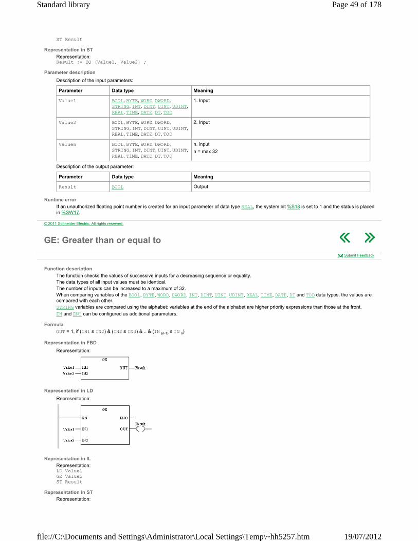
ST Result
Representation in ST
Representation: Result := EQ (Value1, Value2) ;
Parameter description
Description of the input parameters:
Description of the output parameter:
Runtime error
If an unauthorized floating point number is created for an input parameter of data type REAL, the system bit %S18 is set to 1 and the status is placed in %SW17.
Parameter Data type Meaning
Value1 BOOL, BYTE, WORD, DWORD, STRING, INT, DINT, UINT, UDINT, REAL, TIME, DATE, DT, TOD
1. Input
Value2 BOOL, BYTE, WORD, DWORD, STRING, INT, DINT, UINT, UDINT, REAL, TIME, DATE, DT, TOD
2. Input
Valuen BOOL, BYTE, WORD, DWORD, STRING, INT, DINT, UINT, UDINT, REAL, TIME, DATE, DT, TOD
n. input
n = max 32
Parameter Data type Meaning
Result BOOL Output
© 2011 Schneider Electric. All rights reserved.
GE: Greater than or equal to
Function description
The function checks the values of successive inputs for a decreasing sequence or equality. The data types of all input values must be identical. The number of inputs can be increased to a maximum of 32. When comparing variables of the BOOL, BYTE, WORD, DWORD, INT, DINT, UINT, UDINT, REAL, TIME, DATE, DT and TOD data types, the values are compared with each other. STRING variables are compared using the alphabet; variables at the end of the alphabet are higher priority expressions than those at the front.
EN and ENO can be configured as additional parameters.
Formula
OUT = 1, if (IN1 ≥ IN2) & (IN2 ≥ IN3) & .. & (IN (n-1) ≥ IN n)
Representation in FBD
Representation:
Representation in LD
Representation:
Representation in IL
Representation: LD Value1 GE Value2 ST Result
Representation in ST
Representation:
Submit Feedback
Page 49 of 178Standard library
19/07/2012file://C:\Documents and Settings\Administrator\Local Settings\Temp\~hh5257.htm
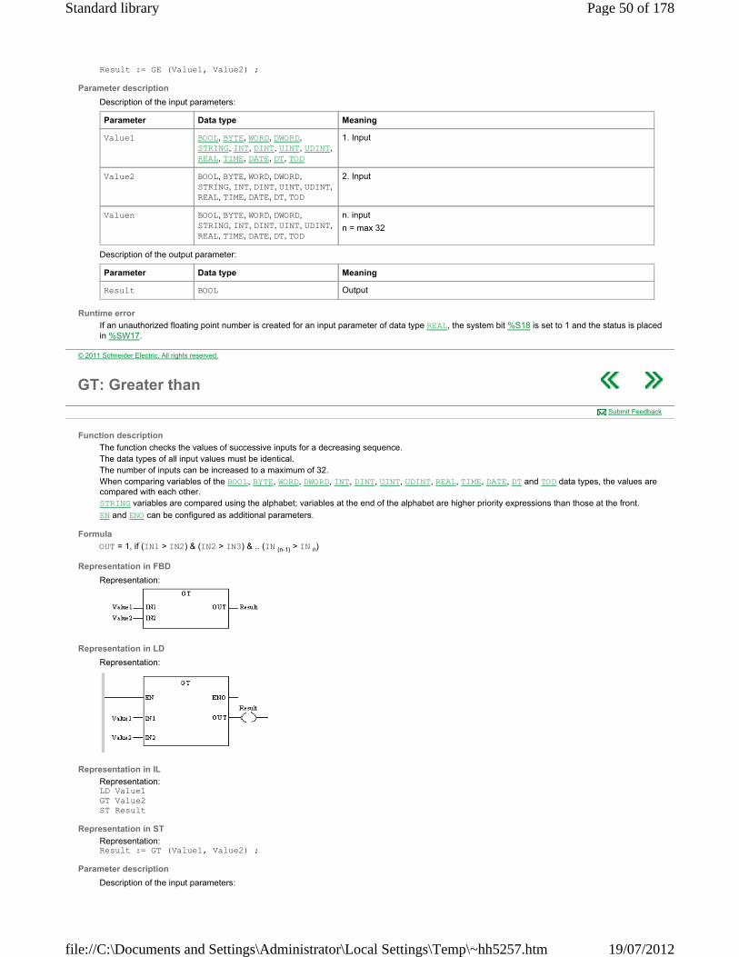
Result := GE (Value1, Value2) ;
Parameter description
Description of the input parameters:
Description of the output parameter:
Runtime error
If an unauthorized floating point number is created for an input parameter of data type REAL, the system bit %S18 is set to 1 and the status is placed in %SW17.
Parameter Data type Meaning
Value1 BOOL, BYTE, WORD, DWORD, STRING, INT, DINT, UINT, UDINT, REAL, TIME, DATE, DT, TOD
1. Input
Value2 BOOL, BYTE, WORD, DWORD, STRING, INT, DINT, UINT, UDINT, REAL, TIME, DATE, DT, TOD
2. Input
Valuen BOOL, BYTE, WORD, DWORD, STRING, INT, DINT, UINT, UDINT, REAL, TIME, DATE, DT, TOD
n. input
n = max 32
Parameter Data type Meaning
Result BOOL Output
© 2011 Schneider Electric. All rights reserved.
GT: Greater than
Function description
The function checks the values of successive inputs for a decreasing sequence. The data types of all input values must be identical. The number of inputs can be increased to a maximum of 32. When comparing variables of the BOOL, BYTE, WORD, DWORD, INT, DINT, UINT, UDINT, REAL, TIME, DATE, DT and TOD data types, the values are compared with each other. STRING variables are compared using the alphabet; variables at the end of the alphabet are higher priority expressions than those at the front.
EN and ENO can be configured as additional parameters.
Formula
OUT = 1, if (IN1 > IN2) & (IN2 > IN3) & .. (IN (n-1) > IN n)
Representation in FBD
Representation:
Representation in LD
Representation:
Representation in IL
Representation: LD Value1 GT Value2 ST Result
Representation in ST
Representation: Result := GT (Value1, Value2) ;
Parameter description
Description of the input parameters:
Submit Feedback
Page 50 of 178Standard library
19/07/2012file://C:\Documents and Settings\Administrator\Local Settings\Temp\~hh5257.htm

Description of the output parameter:
Runtime error
If an unauthorized floating point number is created for an input parameter of data type REAL, the system bit %S18 is set to 1 and the status is placed in %SW17.
Parameter Data type Meaning
Value1 BOOL, BYTE, WORD, DWORD, STRING, INT, DINT, UINT, UDINT, REAL, TIME, DATE, DT, TOD
1. Input
Value2 BOOL, BYTE, WORD, DWORD, STRING, INT, DINT, UINT, UDINT, REAL, TIME, DATE, DT, TOD
2. Input
Valuen BOOL, BYTE, WORD, DWORD, STRING, INT, DINT, UINT, UDINT, REAL, TIME, DATE, DT, TOD
n. input
n = max 32
Parameter Data type Meaning
Result BOOL Output
© 2011 Schneider Electric. All rights reserved.
LE: Less than or equal to
Function description
The function checks the values of successive inputs for an increasing sequence or equality. The data types of all input values must be identical. The number of inputs can be increased to a maximum of 32. When comparing variables of the BOOL, BYTE, WORD, DWORD, INT, DINT, UINT, UDINT, REAL, TIME, DATE, DT and TOD data types, the values are compared with each other. STRING variables are compared using the alphabet; variables at the end of the alphabet are higher priority expressions than those at the front.
EN and ENO can be configured as additional parameters.
Formula
OUT = 1, if (IN1 ≤ IN2) & (IN2 ≤ IN3) & .. & (IN (n-1) ≤ IN n)
Representation in FBD
Representation:
Representation in LD
Representation:
Representation in IL
Representation: LD Value1 LE Value2 ST Result
Representation in ST
Representation: Result := LE (Value1, Value2) ;
Parameter description
Description of the input parameters:
Submit Feedback
Parameter Data type Meaning
Value1 BOOL, BYTE, WORD, DWORD, 1. Input
Page 51 of 178Standard library
19/07/2012file://C:\Documents and Settings\Administrator\Local Settings\Temp\~hh5257.htm

Description of the output parameter:
Runtime error
If an unauthorized floating point number is created for an input parameter of data type REAL, the system bit %S18 is set to 1 and the status is placed in %SW17.
STRING, INT, DINT, UINT, UDINT, REAL, TIME, DATE, DT, TOD
Value2 BOOL, BYTE, WORD, DWORD, STRING, INT, DINT, UINT, UDINT, REAL, TIME, DATE, DT, TOD
2. Input
Valuen BOOL, BYTE, WORD, DWORD, STRING, INT, DINT, UINT, UDINT, REAL, TIME, DATE, DT, TOD
n. input
n = max 32
Parameter Data type Meaning
Result BOOL Output
© 2011 Schneider Electric. All rights reserved.
LT: Less than
Function description
The function checks the values of successive inputs for an increasing sequence. The data types of all input values must be identical. The number of inputs can be increased to a maximum of 32. When comparing variables of the BOOL, BYTE, WORD, DWORD, INT, DINT, UINT, UDINT, REAL, TIME, DATE, DT and TOD data types, the values are compared with each other. STRING variables are compared using the alphabet; variables at the end of the alphabet are higher priority expressions than those at the front.
EN and ENO can be configured as additional parameters.
Formula
OUT = 1, if (IN1 < IN2) & (IN2 < IN3) & .. & (IN (n-1) < IN n)
Representation in FBD
Representation:
Representation in LD
Representation:
Representation in IL
Representation: LD Value1 LT Value2 ST Result
Representation in ST
Representation: Result := LT (Value1, Value2) ;
Parameter description
Description of the input parameters:
Submit Feedback
Parameter Data type Meaning
Value1 BOOL, BYTE, WORD, DWORD, STRING, INT, DINT, UINT, UDINT, REAL, TIME, DATE, DT, TOD
1. Input value
Page 52 of 178Standard library
19/07/2012file://C:\Documents and Settings\Administrator\Local Settings\Temp\~hh5257.htm

Description of the output parameter:
Runtime error
If an unauthorized floating point number is created for an input parameter of data type REAL, the system bit %S18 is set to 1 and the status is placed in %SW17.
Value2 BOOL, BYTE, WORD, DWORD, STRING, INT, DINT, UINT, UDINT, REAL, TIME, DATE, DT, TOD
2. Input value
Valuen BOOL, BYTE, WORD, DWORD, STRING, INT, DINT, UINT, UDINT, REAL, TIME, DATE, DT, TOD
n. input value
n = max 32
Parameter Data type Meaning
Result BOOL Output value
© 2011 Schneider Electric. All rights reserved.
NE: Not equal to
Function description
The function checks the input values for inequality. The data types of the input values must be identical. EN and ENO can be configured as additional parameters.
Formula
OUT = 1, if IN1 < > IN2
Representation in FBD
Representation:
Representation in LD
Representation:
Representation in IL
Representation: LD Value1 NE Value2 ST Result
Representation in ST
Representation: Result := NE (Value1, Value2) ;
Parameter description
Description of the input parameters:
Description of the output parameter:
Submit Feedback
Parameter Data type Meaning
Value1 BOOL, BYTE, WORD, DWORD, STRING, INT, DINT, UINT, UDINT, REAL, TIME, DATE, DT, TOD
1. Input
Value2 BOOL, BYTE, WORD, DWORD, STRING, INT, DINT, UINT, UDINT, REAL, TIME, DATE, DT, TOD
2. Input
Parameter Data type Meaning
Page 53 of 178Standard library
19/07/2012file://C:\Documents and Settings\Administrator\Local Settings\Temp\~hh5257.htm

Runtime error
If an unauthorized floating point number is created for an input parameter of data type REAL, the system bit %S18 is set to 1 and the status is placed in %SW17.
Result BOOL Output
© 2011 Schneider Electric. All rights reserved.
Date & Time
Overview
This section describes the elementary functions and elementary function blocks of the Date & Time family.
What's in this Part?
This part contains the following chapters:
ADD_***_TIME: Addition of a duration to a date DIVTIME: Division MULTIME: Multiplication SUB_***_***: Calculates the time difference between two dates or times SUB_***_TIME: Subtraction of a duration from a date
© 2011 Schneider Electric. All rights reserved.
ADD_***_TIME: Addition of a duration to a date
Function description
The ADD_***_TIME function adds a duration to a date or a time.
The additional parameters EN and ENO can be configured.
Available functions
The available functions are as follows:
ADD_DT_TIME, ADD_TOD_TIME.
Representation in FBD
Representation applied to a time of day:
Representation in LD
Representation applied to a time of day:
Representation in IL
Representation applied to a time of day: LD Source_Value ADD_TOD_TIME Time_to_Add ST Result_Value
Representation in ST
Representation applied to a time of day: Result_Value:= ADD_TOD_TIME(Source_Value, Time_to_Add);
Description of parameters
The following table describes the input parameters:
Submit Feedback
Parameter Type Comment
Source_Value DT, TOD Date or time.
Page 54 of 178Standard library
19/07/2012file://C:\Documents and Settings\Administrator\Local Settings\Temp\~hh5257.htm

The following table describes the output parameters:
NOTE: the management of leap years is to be provided for in the application.
Runtime errors
For the type TOD, there is a change of day if Result_Value is outside the authorized values. In this case, the system bit %S18 is set at 1 and the value of Result_Value is only significant with a modulo 24:00:00.
For the type DT, if Result_Value is outside the interval of authorized values, the system bit %S18 is set to 1 and the value of Result_Value is equal to the maximum limit. If one of the input parameters cannot be interpreted and is inconsistent with the function format then the system bit %S18 is set at 1 and Result_Value applies:
00:00:00 for the type TOD. 00001-01-01-00:00:00 for the type DT.
Time_to_Add TIME Duration to be added to Source_Value
Note: this duration is expressed in TIME format with a precision to the order of tenths of a second. As the types DT and TOD are expressed to the nearest second, Time_to_Add is rounded off to the second.
Parameter Type Comment
Result_Value DT, TOD Result_Value is of the same type as Source_Value.
© 2011 Schneider Electric. All rights reserved.
DIVTIME: Division
Function description
The function divides the value at the TIME_variable (data type TIME) input with the value at the Divisor input and assigns the result to the output. EN and ENO can be configured as additional parameters.
Formula
Representation in FBD
Representation:
Representation in LD
Representation:
Representation in IL
Representation: LD TIME_variable DIVTIME Divisor ST Quotient
Representation in ST
Representation: Quotient := DIVTIME (TIME_variable, Divisor) ;
Parameter description
Description of input parameters:
Description of output parameters:
Submit Feedback
Parameter Data type Meaning
TIME_variable TIME Dividend
Divisor INT, DINT, UINT, UDINT, REAL Divisor
Parameter Data type Meaning
Page 55 of 178Standard library
19/07/2012file://C:\Documents and Settings\Administrator\Local Settings\Temp\~hh5257.htm
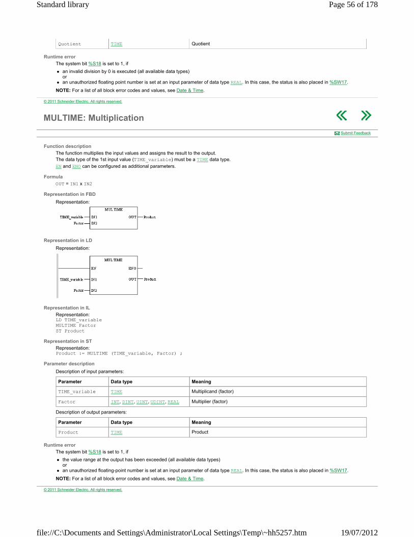
Runtime error
The system bit %S18 is set to 1, if
an invalid division by 0 is executed (all available data types) or
an unauthorized floating point number is set at an input parameter of data type REAL. In this case, the status is also placed in %SW17.
NOTE: For a list of all block error codes and values, see Date & Time.
Quotient TIME Quotient
© 2011 Schneider Electric. All rights reserved.
MULTIME: Multiplication
Function description
The function multiplies the input values and assigns the result to the output. The data type of the 1st input value (TIME_variable) must be a TIME data type.
EN and ENO can be configured as additional parameters.
Formula
OUT = IN1 x IN2
Representation in FBD
Representation:
Representation in LD
Representation:
Representation in IL
Representation: LD TIME_variable MULTIME Factor ST Product
Representation in ST
Representation: Product := MULTIME (TIME_variable, Factor) ;
Parameter description
Description of input parameters:
Description of output parameters:
Runtime error
The system bit %S18 is set to 1, if
the value range at the output has been exceeded (all available data types) or
an unauthorized floating-point number is set at an input parameter of data type REAL. In this case, the status is also placed in %SW17.
NOTE: For a list of all block error codes and values, see Date & Time.
Submit Feedback
Parameter Data type Meaning
TIME_variable TIME Multiplicand (factor)
Factor INT, DINT, UINT, UDINT, REAL Multiplier (factor)
Parameter Data type Meaning
Product TIME Product
© 2011 Schneider Electric. All rights reserved.
Page 56 of 178Standard library
19/07/2012file://C:\Documents and Settings\Administrator\Local Settings\Temp\~hh5257.htm

SUB_***_***: Calculates the time difference between two dates or times
Function description
The SUB_***_*** function calculates the time difference between two dates or times.
The additional parameters EN and ENO can be configured.
Available functions
The available functions are as follows:
SUB_DATE_DATE, SUB_DT_DT, SUB_TOD_TOD.
Representation in FBD
Representation applied to a time of day:
Representation in LD
Representation applied to a time of day:
Representation in IL
Representation applied to a time of day: LD Input_IN1 SUB_TOD_TOD Input_IN2 ST Delay1
Representation in ST
Representation applied to a time of day: Delay1:= =SUB_TOD_TOD(Input_IN1, Input_IN2);
Description of parameters
The following table describes the input parameters:
NOTE: Input_IN1 and Input_IN2 must be of the same type.
The following table describes the output parameters:
Runtime errors
If Delay1 exceeds the maximum value allowed for a TIME format, there is overrun, then Delay1 = 0 and the system bit %S18 is set to 1.
If one of the input parameters is not interpretable and coherent in the function format, then Delay1 = 0 and the system bit %S18 is set to 1.
Submit Feedback
Parameter Type Comment
Input_IN1 DATE, DT, TOD Date or time for which we wish to calculate the difference with Input_IN2.
Input_IN2 DATE, DT, TOD Date or time for which we wish to calculate the difference with Input_IN2.
Of the same type as the elements of the table Input_IN1.
Parameter Type Comment
Delay1 TIME Delay1 contains the time expressed as an absolute value elapsed between the two entries Input_IN1 and Input_IN2.
© 2011 Schneider Electric. All rights reserved.
SUB_***_TIME: Subtraction of a duration from a date
Function description
Submit Feedback
Page 57 of 178Standard library
19/07/2012file://C:\Documents and Settings\Administrator\Local Settings\Temp\~hh5257.htm
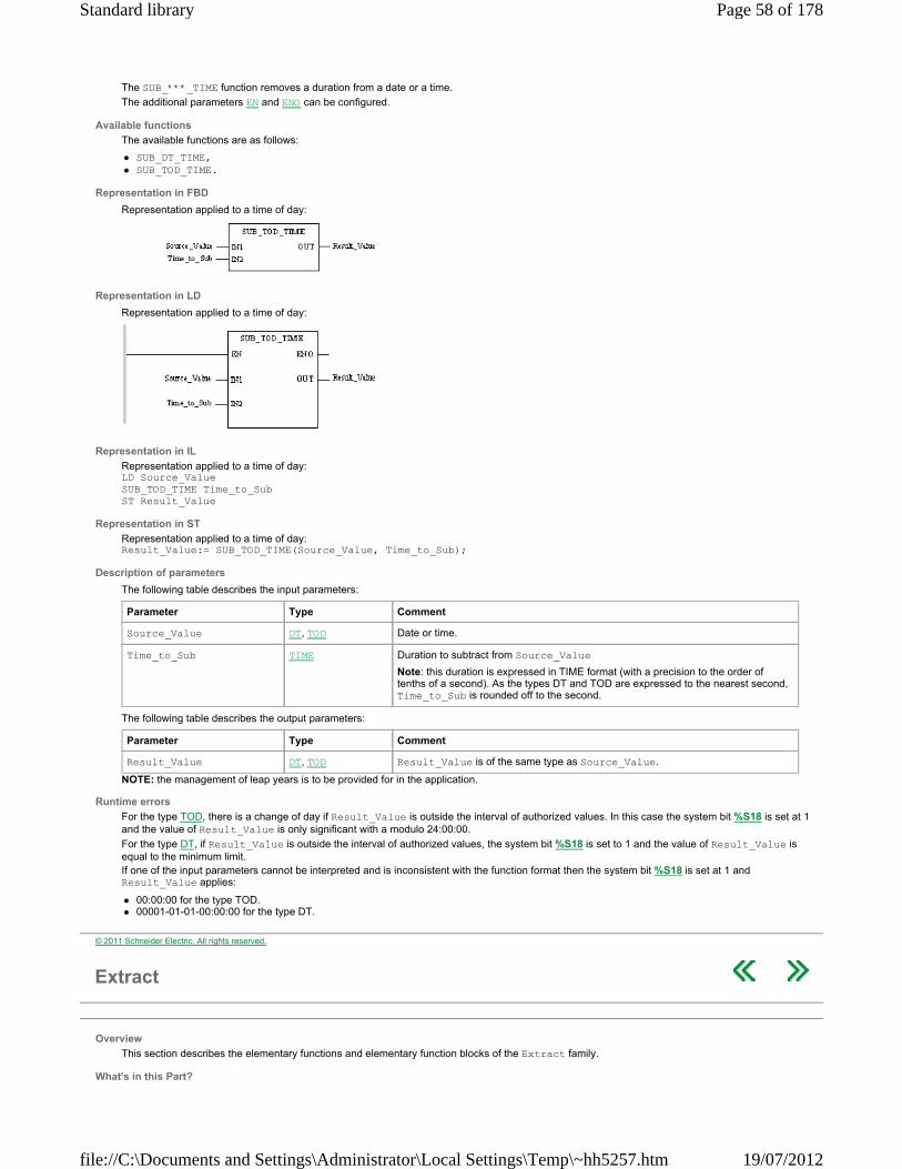
The SUB_***_TIME function removes a duration from a date or a time.
The additional parameters EN and ENO can be configured.
Available functions
The available functions are as follows:
SUB_DT_TIME, SUB_TOD_TIME.
Representation in FBD
Representation applied to a time of day:
Representation in LD
Representation applied to a time of day:
Representation in IL
Representation applied to a time of day: LD Source_Value SUB_TOD_TIME Time_to_Sub ST Result_Value
Representation in ST
Representation applied to a time of day: Result_Value:= SUB_TOD_TIME(Source_Value, Time_to_Sub);
Description of parameters
The following table describes the input parameters:
The following table describes the output parameters:
NOTE: the management of leap years is to be provided for in the application.
Runtime errors
For the type TOD, there is a change of day if Result_Value is outside the interval of authorized values. In this case the system bit %S18 is set at 1 and the value of Result_Value is only significant with a modulo 24:00:00.
For the type DT, if Result_Value is outside the interval of authorized values, the system bit %S18 is set to 1 and the value of Result_Value is equal to the minimum limit. If one of the input parameters cannot be interpreted and is inconsistent with the function format then the system bit %S18 is set at 1 and Result_Value applies:
00:00:00 for the type TOD. 00001-01-01-00:00:00 for the type DT.
Parameter Type Comment
Source_Value DT, TOD Date or time.
Time_to_Sub TIME Duration to subtract from Source_Value
Note: this duration is expressed in TIME format (with a precision to the order of tenths of a second). As the types DT and TOD are expressed to the nearest second, Time_to_Sub is rounded off to the second.
Parameter Type Comment
Result_Value DT, TOD Result_Value is of the same type as Source_Value.
© 2011 Schneider Electric. All rights reserved.
Extract
Overview
This section describes the elementary functions and elementary function blocks of the Extract family.
What's in this Part?
Page 58 of 178Standard library
19/07/2012file://C:\Documents and Settings\Administrator\Local Settings\Temp\~hh5257.htm

This part contains the following chapters:
EXTRACT: Copy of a variable part into another variable SIZEOF: Size of a variable in bytes
© 2011 Schneider Electric. All rights reserved.
EXTRACT: Copy of a variable part into another variable
Function description
The EXTRACT function copies a defined part out of a source variable (SRC) into a destination variable (DST). NOTE: Parts of Arrays of EBOOL and IODDTs can not be copied because SRC and DST are of data type ANY.
Data types of source and destination variables can be different. As SRC and DST are of data type ANY and you can copy any part of a variable to any another variable, there will be no validity check for the copy operation.
The memory size of the source variable (SRC) is identified by the function block (in bytes) internally.
Depending on the alignment of the different PLC platforms the memory size can differ from platform to platform. SRC_NELEM defines the number of parts of the source variable. The memory size of the source variable (in bytes) is divided by SRC_NELEM, and so the size of every part is defined.
Example
The value of SRC_NELEM must allow the division of the memory size of the source variable without remainder.
The number of elements to be copied (CPY_NELEM) out of the source variable starts from a defined position (SRC_POS) and is copied to a defined position in the destination variable (DST_POS). NOTE: SRC_POS and DST_POS define the position of the parts to be copied based on 0 to n.
Example with SRC_NELEM = 10
The additional parameters EN and ENO can be configured.
You can use the SIZEOF function to set the value of SRC_NELEM input to the number of bytes of the source variable.
Representation in FBD
Representation:
Representation in LD
Representation:
Submit Feedback
WARNING UNINTENDED EQUIPMENT OPERATION
Check the results of all modified variables before re-starting your process application.
Failure to follow these instructions can result in death, serious injury, or equipment damage.
Variable SRC_NELEM Size of part
ARRAY[0..9] OF WORD 5 DWORD (4 bytes)
10 WORD (2 bytes)
20 BYTE
Variable SRC_POS Position in ARRAY
ARRAY[0..9] OF WORD 2 2
ARRAY[5..14] OF WORD 2 7
Page 59 of 178Standard library
19/07/2012file://C:\Documents and Settings\Administrator\Local Settings\Temp\~hh5257.htm
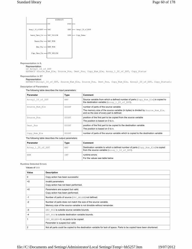
Representation in IL
Representation: LD Array1_10_of_DDT EXTRACT Source_Num_Ele, Source_Pos, Dest_Pos, Copy_Num_Ele, Array_1_20_of_DDT, Copy_Status
Representation in ST
Representation: EXTRACT(Array1_10_of_DDT, Source_Num_Ele, Source_Pos, Dest_Pos, Copy_Num_Ele, Array1_20_of_DDT, Copy_Status);
Description of Parameters
The following table describes the input parameters:
The following table describes the output parameters:
Runtime Detected Errors
Values of ERR
Parameter Type Comment
Array1_10_of_DDT ANY Source variable from which a defined number of parts (Copy_Num_Ele) is copied to the destination variable (Array_1_20_of_DDT).
Source_Num_Ele UDINT number of parts of the source variable
The memory size of the source variable (in bytes) is divided by Source_Num_Ele, and so the size of every part is defined.
Source_Pos UDINT position of the first part to be copied from the source variable
The position is based on 0 to n.
Dest_Pos UDINT position of the first part to be copied to the destination variable
The position is based on 0 to n.
Copy_Num_Ele UDINT number of parts of the source variable which is copied to the destination variable
Parameter Type Comment
Array_1_20_of_DDT ANY Destination variable to which a defined number of parts (Copy_Num_Ele) is copied from the source variable (Array_1_10_of_DDT).
ERR INT runtime errors
For the values see table below
Value Description
0 Copy action has been successful.
<0 invalid parameters
Copy action has not been performed.
>0 Parameters are suspect but valid.
Copy action has been performed.
-1 Number of parts of source (SRC_NELEM) not defined.
-2 Number of parts does not match the size of the source variable.
Memory size of the source variable is not divisible without remainder.
-3 SRC_POS is outside source variable bounds.
-4 DST_POS is outside destination variable bounds.
1 CPY_NELEM = 0, no parts to be copied
Parameter is suspect but valid.
2 Not all parts could be copied to the destination variable for lack of space. Parts to be copied have been shortened.
Page 60 of 178Standard library
19/07/2012file://C:\Documents and Settings\Administrator\Local Settings\Temp\~hh5257.htm
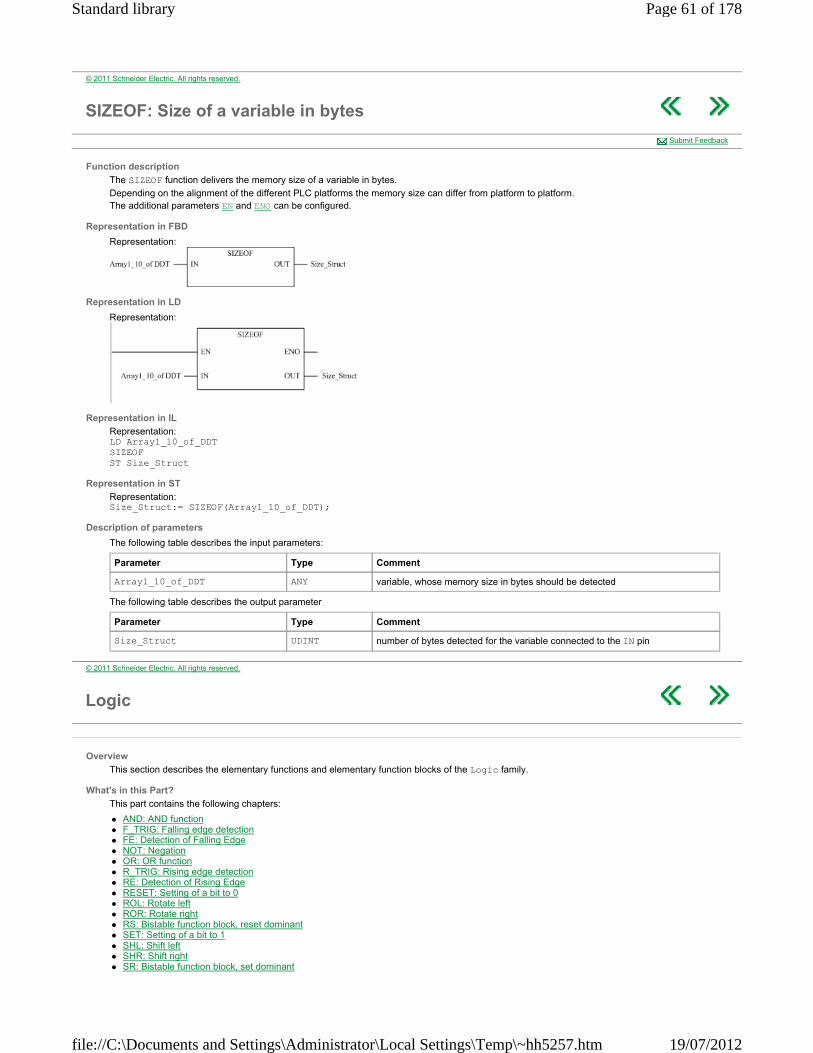
© 2011 Schneider Electric. All rights reserved.
SIZEOF: Size of a variable in bytes
Function description
The SIZEOF function delivers the memory size of a variable in bytes.
Depending on the alignment of the different PLC platforms the memory size can differ from platform to platform. The additional parameters EN and ENO can be configured.
Representation in FBD
Representation:
Representation in LD
Representation:
Representation in IL
Representation: LD Array1_10_of_DDT SIZEOF ST Size_Struct
Representation in ST
Representation: Size_Struct:= SIZEOF(Array1_10_of_DDT);
Description of parameters
The following table describes the input parameters:
The following table describes the output parameter
Submit Feedback
Parameter Type Comment
Array1_10_of_DDT ANY variable, whose memory size in bytes should be detected
Parameter Type Comment
Size_Struct UDINT number of bytes detected for the variable connected to the IN pin
© 2011 Schneider Electric. All rights reserved.
Logic
Overview
This section describes the elementary functions and elementary function blocks of the Logic family.
What's in this Part?
This part contains the following chapters:
AND: AND function F_TRIG: Falling edge detection FE: Detection of Falling Edge NOT: Negation OR: OR function R_TRIG: Rising edge detection RE: Detection of Rising Edge RESET: Setting of a bit to 0 ROL: Rotate left ROR: Rotate right RS: Bistable function block, reset dominant SET: Setting of a bit to 1 SHL: Shift left SHR: Shift right SR: Bistable function block, set dominant
Page 61 of 178Standard library
19/07/2012file://C:\Documents and Settings\Administrator\Local Settings\Temp\~hh5257.htm
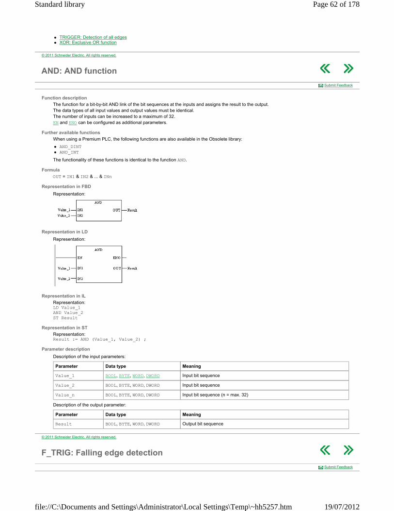
TRIGGER: Detection of all edges XOR: Exclusive OR function
© 2011 Schneider Electric. All rights reserved.
AND: AND function
Function description
The function for a bit-by-bit AND link of the bit sequences at the inputs and assigns the result to the output. The data types of all input values and output values must be identical. The number of inputs can be increased to a maximum of 32. EN and ENO can be configured as additional parameters.
Further available functions
When using a Premium PLC, the following functions are also available in the Obsolete library:
AND_DINT AND_INT
The functionality of these functions is identical to the function AND.
Formula
OUT = IN1 & IN2 & ... & INn
Representation in FBD
Representation:
Representation in LD
Representation:
Representation in IL
Representation: LD Value_1 AND Value_2 ST Result
Representation in ST
Representation: Result := AND (Value_1, Value_2) ;
Parameter description
Description of the input parameters:
Description of the output parameter:
Submit Feedback
Parameter Data type Meaning
Value_1 BOOL, BYTE, WORD, DWORD Input bit sequence
Value_2 BOOL, BYTE, WORD, DWORD Input bit sequence
Value_n BOOL, BYTE, WORD, DWORD Input bit sequence (n = max. 32)
Parameter Data type Meaning
Result BOOL, BYTE, WORD, DWORD Output bit sequence
© 2011 Schneider Electric. All rights reserved.
F_TRIG: Falling edge detection
Submit Feedback
Page 62 of 178Standard library
19/07/2012file://C:\Documents and Settings\Administrator\Local Settings\Temp\~hh5257.htm
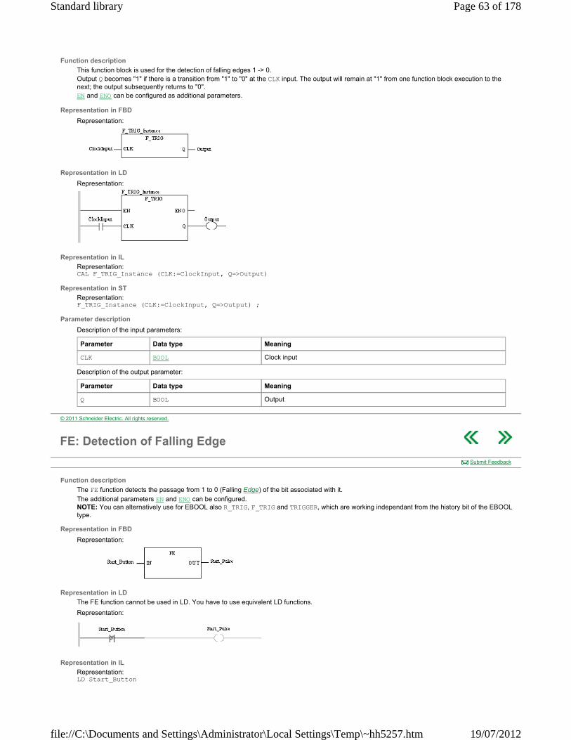
Function description
This function block is used for the detection of falling edges 1 -> 0. Output Q becomes "1" if there is a transition from "1" to "0" at the CLK input. The output will remain at "1" from one function block execution to the next; the output subsequently returns to "0". EN and ENO can be configured as additional parameters.
Representation in FBD
Representation:
Representation in LD
Representation:
Representation in IL
Representation: CAL F_TRIG_Instance (CLK:=ClockInput, Q=>Output)
Representation in ST
Representation: F_TRIG_Instance (CLK:=ClockInput, Q=>Output) ;
Parameter description
Description of the input parameters:
Description of the output parameter:
Parameter Data type Meaning
CLK BOOL Clock input
Parameter Data type Meaning
Q BOOL Output
© 2011 Schneider Electric. All rights reserved.
FE: Detection of Falling Edge
Function description
The FE function detects the passage from 1 to 0 (Falling Edge) of the bit associated with it.
The additional parameters EN and ENO can be configured. NOTE: You can alternatively use for EBOOL also R_TRIG, F_TRIG and TRIGGER, which are working independant from the history bit of the EBOOL type.
Representation in FBD
Representation:
Representation in LD
The FE function cannot be used in LD. You have to use equivalent LD functions.
Representation:
Representation in IL
Representation: LD Start_Button
Submit Feedback
Page 63 of 178Standard library
19/07/2012file://C:\Documents and Settings\Administrator\Local Settings\Temp\~hh5257.htm

FE ST Start_Pulse
Representation in ST
Representation: Start_Pulse:= FE (Start_Button);
Description of parameters
The following table describes the input parameters:
The following table describes the output parameters:
The EBOOL variable has to be written once in every scan of the CPU. In all other cases a malfunction is possible. Only the discrete input can be used without restrictions, because it is written from the I/O management of the CPU.
Trend diagram
Timing diagram:
T is equal to a PLC cycle time for an input and is the delay between two assignments for a discrete output or an internal bit.
Parameter Type Comment
Start_Button EBOOL Discrete input or output or internal bit whose Falling Edge we wish to detect.
Parameter Type Comment
Start_Pulse BOOL Internal bit or output representing the Falling Edge.
T
© 2011 Schneider Electric. All rights reserved.
NOT: Negation
Function description
The function negates the input bit sequence bit-by-bit and assigns the result to the output. The data types of the input and output values must be identical. EN and ENO can be configured as additional parameters.
Further available functions
The Obsolete library provides the following additional functions:
NOT_DINT NOT_INT
The functionality of these functions is identical to the function NOT.
Formula
OUT = NOT IN
Representation in FBD
Representation:
Representation in LD
Representation:
Representation in IL
Representation: LD Value NOT
Submit Feedback
Page 64 of 178Standard library
19/07/2012file://C:\Documents and Settings\Administrator\Local Settings\Temp\~hh5257.htm
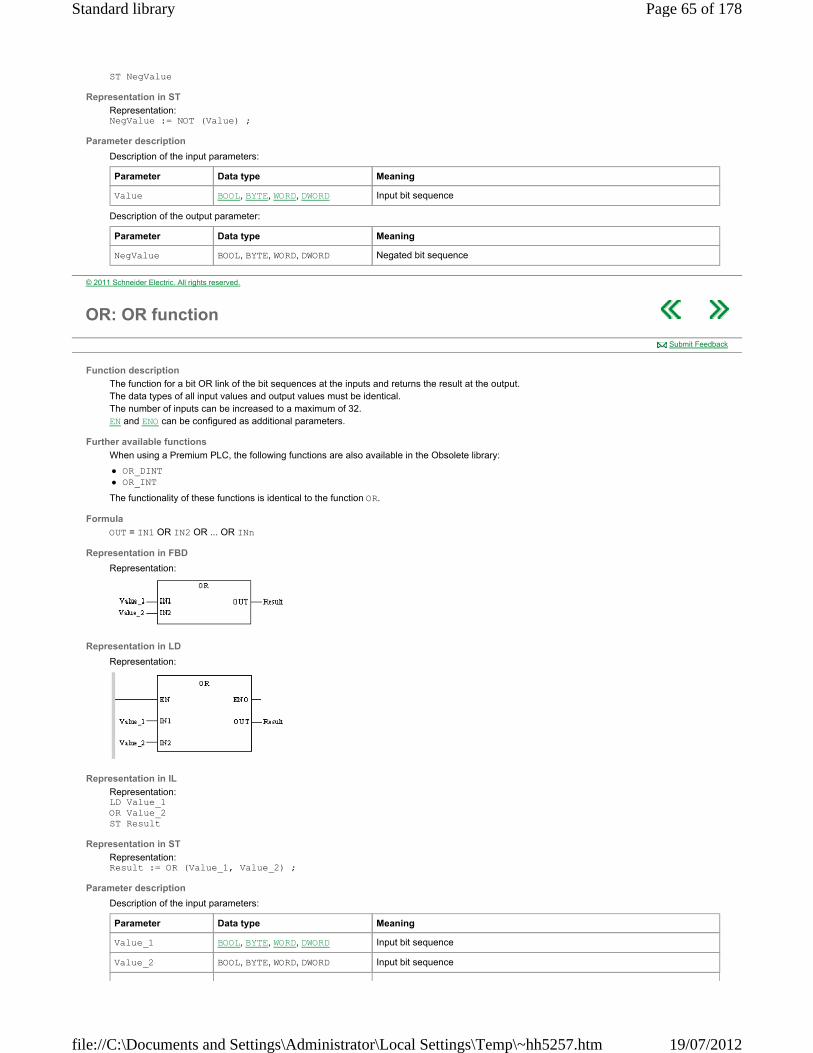
ST NegValue
Representation in ST
Representation: NegValue := NOT (Value) ;
Parameter description
Description of the input parameters:
Description of the output parameter:
Parameter Data type Meaning
Value BOOL, BYTE, WORD, DWORD Input bit sequence
Parameter Data type Meaning
NegValue BOOL, BYTE, WORD, DWORD Negated bit sequence
© 2011 Schneider Electric. All rights reserved.
OR: OR function
Function description
The function for a bit OR link of the bit sequences at the inputs and returns the result at the output. The data types of all input values and output values must be identical. The number of inputs can be increased to a maximum of 32. EN and ENO can be configured as additional parameters.
Further available functions
When using a Premium PLC, the following functions are also available in the Obsolete library:
OR_DINT OR_INT
The functionality of these functions is identical to the function OR.
Formula
OUT = IN1 OR IN2 OR ... OR INn
Representation in FBD
Representation:
Representation in LD
Representation:
Representation in IL
Representation: LD Value_1 OR Value_2 ST Result
Representation in ST
Representation: Result := OR (Value_1, Value_2) ;
Parameter description
Description of the input parameters:
Submit Feedback
Parameter Data type Meaning
Value_1 BOOL, BYTE, WORD, DWORD Input bit sequence
Value_2 BOOL, BYTE, WORD, DWORD Input bit sequence
Page 65 of 178Standard library
19/07/2012file://C:\Documents and Settings\Administrator\Local Settings\Temp\~hh5257.htm
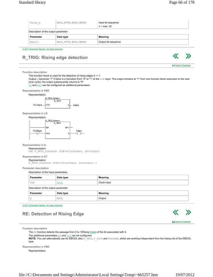
Description of the output parameter:
Value_n BOOL, BYTE, WORD, DWORD Input bit sequence
n = max. 32
Parameter Data type Meaning
Result BOOL, BYTE, WORD, DWORD Output bit sequence
© 2011 Schneider Electric. All rights reserved.
R_TRIG: Rising edge detection
Function description
This function block is used for the detection of rising edges 0 -> 1. Output Q becomes "1" if there is a transition from "0" to "1" at the CLK input. The output remains at "1" from one function block execution to the next (one cycle); the output subsequently returns to "0". EN and ENO can be configured as additional parameters.
Representation in FBD
Representation:
Representation in LD
Representation:
Representation in IL
Representation: CAL R_TRIG_Instance (CLK:=ClockInput, Q=>Output)
Representation in ST
Representation: R_TRIG_Instance (CLK:=ClockInput, Q=>Output) ;
Parameter description
Description of the input parameters:
Description of the output parameter:
Submit Feedback
Parameter Data type Meaning
CLK BOOL Clock input
Parameter Data type Meaning
Q BOOL Output
© 2011 Schneider Electric. All rights reserved.
RE: Detection of Rising Edge
Function description
The RE function detects the passage from 0 to 1(Rising Edge) of the bit associated with it.
The additional parameters EN and ENO can be configured. NOTE: You can alternatively use for EBOOL also R_TRIG, F_TRIG and TRIGGER, which are working independant from the history bit of the EBOOL type.
Representation in FBD
Representation:
Submit Feedback
Page 66 of 178Standard library
19/07/2012file://C:\Documents and Settings\Administrator\Local Settings\Temp\~hh5257.htm

Representation in LD
The RE function cannot be used in LD. You have to use equivalent LD functions
Representation:
Representation in IL
Representation: LD Start_Button RE ST Start_Pulse
Representation in ST
Representation: Start_Pulse := RE (Start_Button);
Description of parameters
The following table describes the input parameters:
The following table describes the output parameters:
The EBOOL variable has to be written once in every scan of the CPU. In all other cases a malfunction is possible. Only the discrete input can be used without restrictions, because it is written from the I/O management of the CPU.
Trend diagram
Timing diagram:
T is equal to a PLC cycle time for an input and is the delay between two assignments for a discrete output or an internal bit.
Parameter Type Comment
Start_Button EBOOL Discrete input or output, internal bit whose Rising Edge we wish to detect
Parameter Type Comment
Start_Pulse BOOL Internal bit or output representing the Rising Edge.
T
© 2011 Schneider Electric. All rights reserved.
RESET: Setting of a bit to 0
Function description
The RESET function sets the bit associated with it to zero.
Representation in FBD
Representation:
Representation in LD
Representation:
Submit Feedback
Page 67 of 178Standard library
19/07/2012file://C:\Documents and Settings\Administrator\Local Settings\Temp\~hh5257.htm
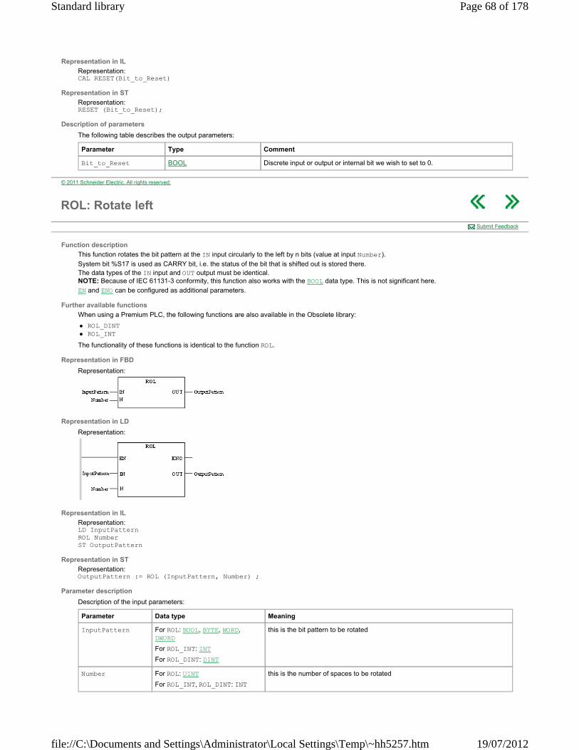
Representation in IL
Representation: CAL RESET(Bit_to_Reset)
Representation in ST
Representation: RESET (Bit_to_Reset);
Description of parameters
The following table describes the output parameters:
Parameter Type Comment
Bit_to_Reset BOOL Discrete input or output or internal bit we wish to set to 0.
© 2011 Schneider Electric. All rights reserved.
ROL: Rotate left
Function description
This function rotates the bit pattern at the IN input circularly to the left by n bits (value at input Number).
System bit %S17 is used as CARRY bit, i.e. the status of the bit that is shifted out is stored there. The data types of the IN input and OUT output must be identical. NOTE: Because of IEC 61131-3 conformity, this function also works with the BOOL data type. This is not significant here.
EN and ENO can be configured as additional parameters.
Further available functions
When using a Premium PLC, the following functions are also available in the Obsolete library:
ROL_DINT ROL_INT
The functionality of these functions is identical to the function ROL.
Representation in FBD
Representation:
Representation in LD
Representation:
Representation in IL
Representation: LD InputPattern ROL Number ST OutputPattern
Representation in ST
Representation: OutputPattern := ROL (InputPattern, Number) ;
Parameter description
Description of the input parameters:
Submit Feedback
Parameter Data type Meaning
InputPattern For ROL: BOOL, BYTE, WORD, DWORD
For ROL_INT: INT
For ROL_DINT: DINT
this is the bit pattern to be rotated
Number For ROL: UINT
For ROL_INT, ROL_DINT: INT
this is the number of spaces to be rotated
Page 68 of 178Standard library
19/07/2012file://C:\Documents and Settings\Administrator\Local Settings\Temp\~hh5257.htm
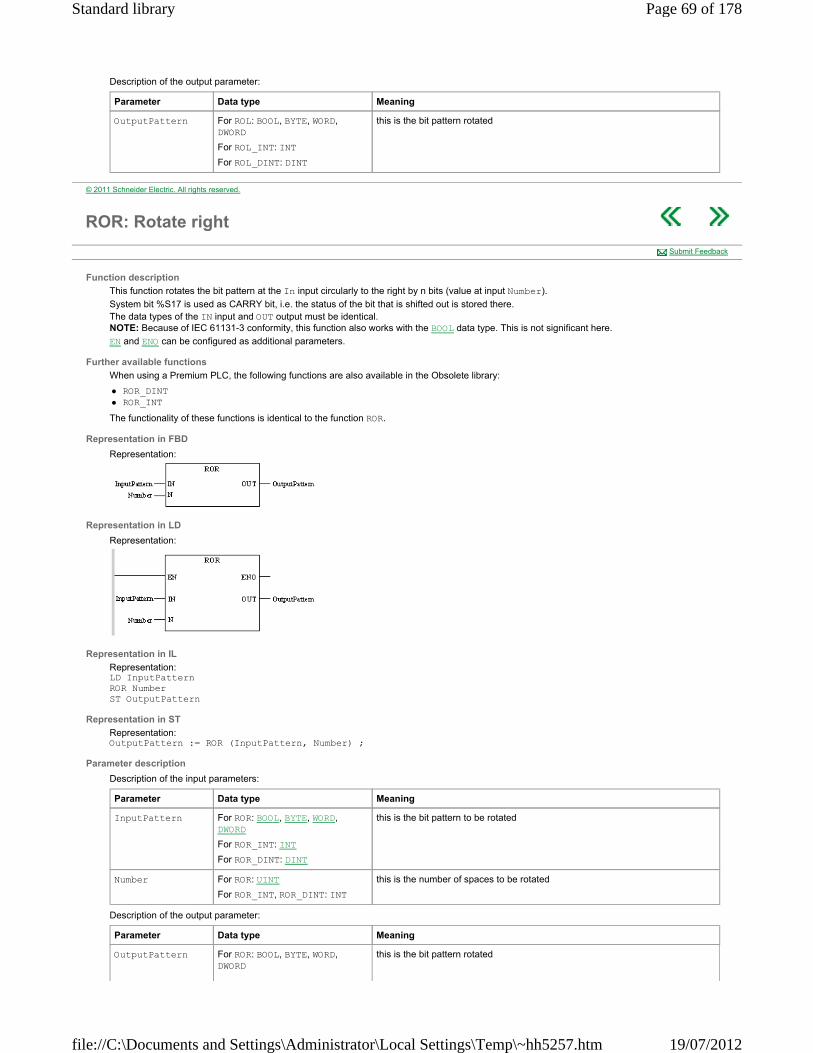
Description of the output parameter:
Parameter Data type Meaning
OutputPattern For ROL: BOOL, BYTE, WORD, DWORD
For ROL_INT: INT
For ROL_DINT: DINT
this is the bit pattern rotated
© 2011 Schneider Electric. All rights reserved.
ROR: Rotate right
Function description
This function rotates the bit pattern at the In input circularly to the right by n bits (value at input Number).
System bit %S17 is used as CARRY bit, i.e. the status of the bit that is shifted out is stored there. The data types of the IN input and OUT output must be identical. NOTE: Because of IEC 61131-3 conformity, this function also works with the BOOL data type. This is not significant here.
EN and ENO can be configured as additional parameters.
Further available functions
When using a Premium PLC, the following functions are also available in the Obsolete library:
ROR_DINT ROR_INT
The functionality of these functions is identical to the function ROR.
Representation in FBD
Representation:
Representation in LD
Representation:
Representation in IL
Representation: LD InputPattern ROR Number ST OutputPattern
Representation in ST
Representation: OutputPattern := ROR (InputPattern, Number) ;
Parameter description
Description of the input parameters:
Description of the output parameter:
Submit Feedback
Parameter Data type Meaning
InputPattern For ROR: BOOL, BYTE, WORD, DWORD
For ROR_INT: INT
For ROR_DINT: DINT
this is the bit pattern to be rotated
Number For ROR: UINT
For ROR_INT, ROR_DINT: INT
this is the number of spaces to be rotated
Parameter Data type Meaning
OutputPattern For ROR: BOOL, BYTE, WORD, DWORD
this is the bit pattern rotated
Page 69 of 178Standard library
19/07/2012file://C:\Documents and Settings\Administrator\Local Settings\Temp\~hh5257.htm
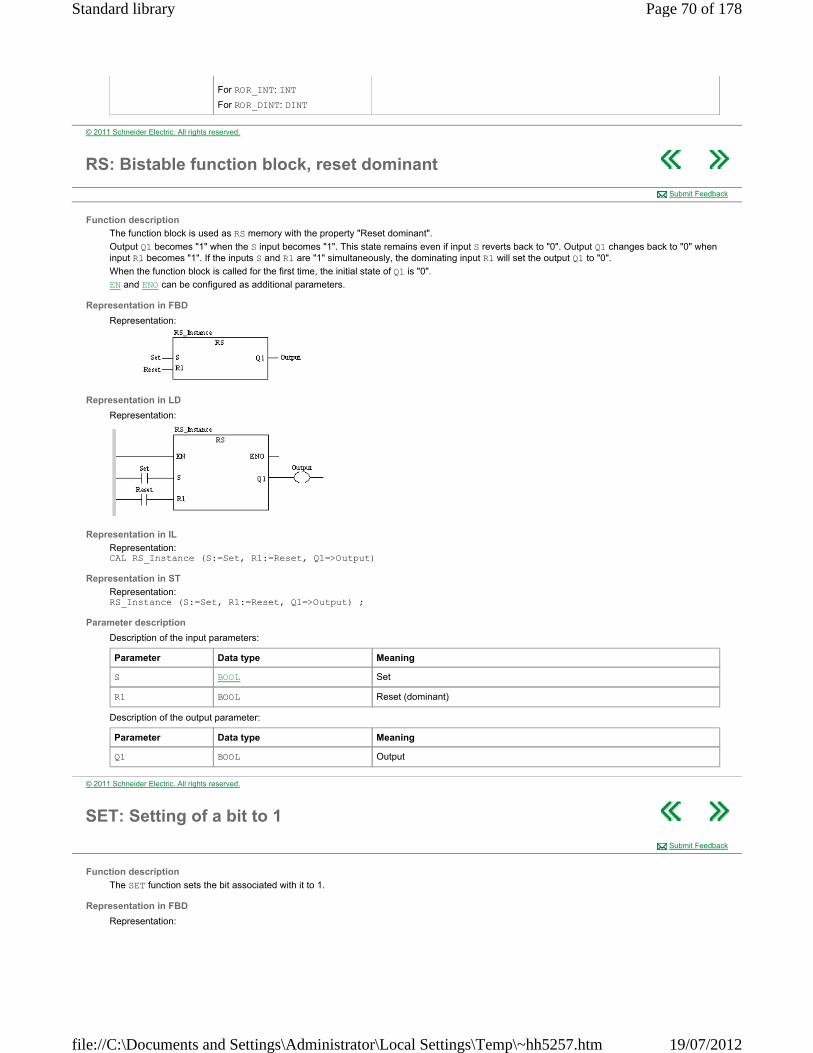
For ROR_INT: INT
For ROR_DINT: DINT
© 2011 Schneider Electric. All rights reserved.
RS: Bistable function block, reset dominant
Function description
The function block is used as RS memory with the property "Reset dominant".
Output Q1 becomes "1" when the S input becomes "1". This state remains even if input S reverts back to "0". Output Q1 changes back to "0" when input R1 becomes "1". If the inputs S and R1 are "1" simultaneously, the dominating input R1 will set the output Q1 to "0".
When the function block is called for the first time, the initial state of Q1 is "0".
EN and ENO can be configured as additional parameters.
Representation in FBD
Representation:
Representation in LD
Representation:
Representation in IL
Representation: CAL RS_Instance (S:=Set, R1:=Reset, Q1=>Output)
Representation in ST
Representation: RS_Instance (S:=Set, R1:=Reset, Q1=>Output) ;
Parameter description
Description of the input parameters:
Description of the output parameter:
Submit Feedback
Parameter Data type Meaning
S BOOL Set
R1 BOOL Reset (dominant)
Parameter Data type Meaning
Q1 BOOL Output
© 2011 Schneider Electric. All rights reserved.
SET: Setting of a bit to 1
Function description
The SET function sets the bit associated with it to 1.
Representation in FBD
Representation:
Submit Feedback
Page 70 of 178Standard library
19/07/2012file://C:\Documents and Settings\Administrator\Local Settings\Temp\~hh5257.htm

Representation in LD
Representation:
Representation in IL
Representation: CAL SET(Bit_to_Set)
Representation in ST
Representation: SET (Bit_to_Set);
Description of parameters
The following table describes the output parameters:
Parameter Type Comment
Bit_to_Set BOOL Discrete input or output or internal bit we wish to set to 1.
© 2011 Schneider Electric. All rights reserved.
SHL: Shift left
Function description
This function shifts the bit pattern at the IN input to the left by n bits (value at input N).
System bit %S17 is used as CARRY bit, i.e. the status of the bit that is shifted out is stored there. Zeros are filled in from the right. The data types of the IN input and OUT output must be identical. NOTE: Because of IEC 61131-3 conformity, this function also works with the BOOL data type. This is not significant here.
EN and ENO can be configured as additional parameters.
Further available functions
Additionally, the Obsolete library provides the following functions:
SHL_DINT SHL_INT
The functionality of these functions is identical to the function SHL.
Representation in FBD
Representation:
Representation in LD
Representation:
Representation in IL
Representation: LD IntputPattern SHL Number ST ShiftedPattern
Representation in ST
Representation: ShiftedPattern := SHL (IntputPattern, Number) ;
Submit Feedback
Page 71 of 178Standard library
19/07/2012file://C:\Documents and Settings\Administrator\Local Settings\Temp\~hh5257.htm
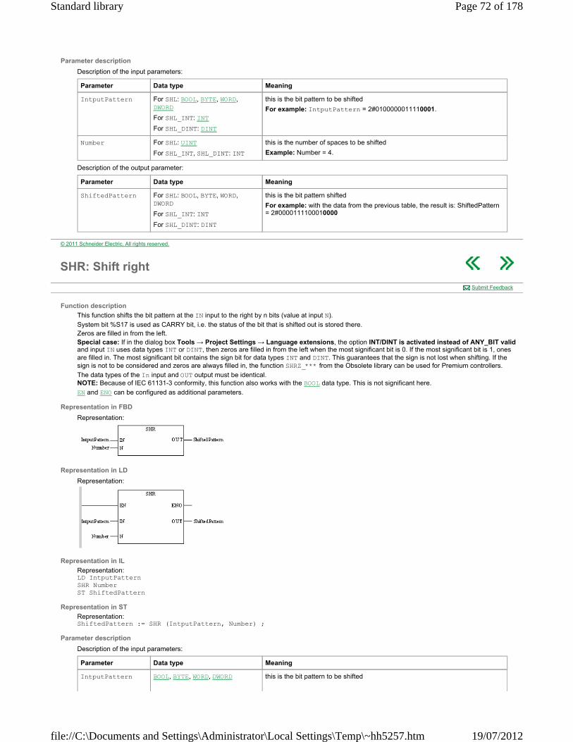
Parameter description
Description of the input parameters:
Description of the output parameter:
Parameter Data type Meaning
IntputPattern For SHL: BOOL, BYTE, WORD, DWORD
For SHL_INT: INT
For SHL_DINT: DINT
this is the bit pattern to be shifted
For example: IntputPattern = 2#0100000011110001.
Number For SHL: UINT
For SHL_INT, SHL_DINT: INT
this is the number of spaces to be shifted
Example: Number = 4.
Parameter Data type Meaning
ShiftedPattern For SHL: BOOL, BYTE, WORD, DWORD
For SHL_INT: INT
For SHL_DINT: DINT
this is the bit pattern shifted
For example: with the data from the previous table, the result is: ShiftedPattern = 2#0000111100010000
© 2011 Schneider Electric. All rights reserved.
SHR: Shift right
Function description
This function shifts the bit pattern at the IN input to the right by n bits (value at input N).
System bit %S17 is used as CARRY bit, i.e. the status of the bit that is shifted out is stored there. Zeros are filled in from the left. Special case: If in the dialog box Tools → Project Settings → Language extensions, the option INT/DINT is activated instead of ANY_BIT valid and input IN uses data types INT or DINT, then zeros are filled in from the left when the most significant bit is 0. If the most significant bit is 1, ones are filled in. The most significant bit contains the sign bit for data types INT and DINT. This guarantees that the sign is not lost when shifting. If the sign is not to be considered and zeros are always filled in, the function SHRZ_*** from the Obsolete library can be used for Premium controllers.
The data types of the In input and OUT output must be identical. NOTE: Because of IEC 61131-3 conformity, this function also works with the BOOL data type. This is not significant here.
EN and ENO can be configured as additional parameters.
Representation in FBD
Representation:
Representation in LD
Representation:
Representation in IL
Representation: LD IntputPattern SHR Number ST ShiftedPattern
Representation in ST
Representation: ShiftedPattern := SHR (IntputPattern, Number) ;
Parameter description
Description of the input parameters:
Submit Feedback
Parameter Data type Meaning
IntputPattern BOOL, BYTE, WORD, DWORD this is the bit pattern to be shifted
Page 72 of 178Standard library
19/07/2012file://C:\Documents and Settings\Administrator\Local Settings\Temp\~hh5257.htm

Description of the output parameter:
For example: IntputPattern = 2#0100000011110001.
Number UINT this is the number of spaces to be shifted
Example: Number = 4.
Parameter Data type Meaning
ShiftedPattern BOOL, BYTE, WORD, DWORD this is the bit pattern shifted
For example: with the data from the previous table, the result is: ShiftedPattern = 2#0000010000001111
© 2011 Schneider Electric. All rights reserved.
SR: Bistable function block, set dominant
Function description
The function block is used as SR memory with the property "Set dominant".
Output Q1 becomes "1" when the S1 input becomes "1". This state remains even if input S1 reverts back to "0". Output Q1 changes back to "0" when input R becomes "1". If the inputs S1 and R are both "1" simultaneously, the dominating input S1 will set the output Q1 to "1".
When the function block is called for the first time, the initial state of Q1 is "0".
EN and ENO can be configured as additional parameters.
Representation in FBD
Representation:
Representation in LD
Representation:
Representation in IL
Representation: CAL SR_Instance (S1:=Set, R:=Reset, Q1=>Output)
Representation in ST
Representation: SR_Instance (S1:=Set, R:=Reset, Q1=>Output) ;
Parameter description
Description of the input parameters:
Description of the output parameter:
Submit Feedback
Parameter Data type Meaning
S1 BOOL Set (dominant)
R BOOL Reset
Parameter Data type Meaning
Q1 BOOL Output
© 2011 Schneider Electric. All rights reserved.
TRIGGER: Detection of all edges
Function description
Submit Feedback
Page 73 of 178Standard library
19/07/2012file://C:\Documents and Settings\Administrator\Local Settings\Temp\~hh5257.htm

The function block recognizes all types of edges (1 -> 0 and 0 -> 1) at the CLK input.
At a rising edge, a transition from "0" to "1"occurs on the CLK input; at a falling edge, a transition from "1" to "0" occurs on the CLK input.
At any edge, the EDGE output becomes "1".
At a rising edge, the EDGE output and the RISE output become "1".
At a falling edge, the EDGE output and the FALL output become "1". If no edge occurs, all outputs are "0".
EN and ENO can be configured as additional parameters.
Representation in FBD
Representation:
Representation in LD
Representation:
Representation in IL
Representation: CAL TRIGGER_Instance (CLK:=ClockInput, RISE=>RisingEdge, EDGE=>AnyEdge, FALL=>FallingEdge)
Representation in ST
Representation: TRIGGER_Instance (CLK:=ClockInput, RISE=>RisingEdge, EDGE=>AnyEdge, FALL=>FallingEdge) ;
Parameter description
Description of the input parameters:
Description of the output parameter:
Parameter Data type Meaning
CLK BOOL Clock input
Parameter Data type Meaning
RISE BOOL Indicator of a rising edge
EDGE BOOL Indicator of all types of edges
FALL BOOL Indicator of a falling edge
© 2011 Schneider Electric. All rights reserved.
XOR: Exclusive OR function
Function description
The function for a bit XOR link of the bit sequences at the inputs and returns the result at the output. The data types of all input values and output values must be identical. The number of inputs can be increased to a maximum of 32. EN and ENO can be configured as additional parameters.
Further available functions
When using a Premium PLC, the following functions are also available in the Obsolete library:
XOR_DINT XOR_INT
The functionality of these functions is identical to the function XOR.
Formula
OUT = IN1 XOR IN2 XOR .. XOR INn
Submit Feedback
Page 74 of 178Standard library
19/07/2012file://C:\Documents and Settings\Administrator\Local Settings\Temp\~hh5257.htm
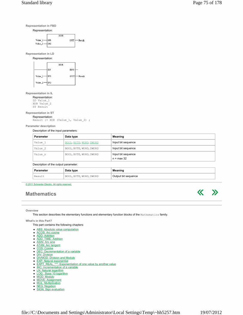
Representation in FBD
Representation:
Representation in LD
Representation:
Representation in IL
Representation: LD Value_1 XOR Value_2 ST Result
Representation in ST
Representation: Result := XOR (Value_1, Value_2) ;
Parameter description
Description of the input parameters:
Description of the output parameter:
Parameter Data type Meaning
Value_1 BOOL, BYTE, WORD, DWORD Input bit sequence
Value_2 BOOL, BYTE, WORD, DWORD Input bit sequence
Value_n BOOL, BYTE, WORD, DWORD Input bit sequence
n = max 32
Parameter Data type Meaning
Result BOOL, BYTE, WORD, DWORD Output bit sequence
© 2011 Schneider Electric. All rights reserved.
Mathematics
Overview
This section describes the elementary functions and elementary function blocks of the Mathematics family.
What's in this Part?
This part contains the following chapters:
ABS: Absolute value computation ACOS: Arc cosine ADD: Addition ADD_TIME: Addition ASIN: Arc sine ATAN: Arc tangent COS: Cosine DEC: Decrementation of a variable DIV: Division DIVMOD: Division and Modulo EXP: Natural exponential EXPT_REAL_***: Exponentiation of one value by another value INC: Incrementation of a variable LN: Natural logarithm LOG : Base 10 logarithm MOD: Modulo MOVE: Assignment MUL: Multiplication NEG: Negation SIGN: Sign evaluation
Page 75 of 178Standard library
19/07/2012file://C:\Documents and Settings\Administrator\Local Settings\Temp\~hh5257.htm

SIN: Sine SUB: Subtraction SUB_TIME: Subtraction SQRT_*** : Square root TAN: Tangent
© 2011 Schneider Electric. All rights reserved.
ABS: Absolute value computation
Function description
The function computes the absolute value of the input value and assigns the result to the output. The data types of the input and output values must be identical. NOTE: Because of IEC 61131-3 conformity, this function also works with the UINT and UDINT data types. This is not significant here.
EN and ENO can be configured as additional parameters.
Formula
Representation in FBD
Representation:
Representation in LD
Representation:
Representation in IL
Representation: LD Value ABS ST Result
Representation in ST
Representation: Result := ABS (Value) ;
Parameter description
Description of the input parameters:
Description of the output parameter:
Runtime error
The system bit %S18 is set to 1, if
a value is below a limit value (data types INT and DINT) or
an unauthorized floating point number is set at an input parameter of data type REAL. In this case, the status is also placed in %SW17.
Submit Feedback
Parameter Data type Meaning
Value INT, DINT, UINT, UDINT, REAL Input value
Parameter Data type Meaning
Result INT, DINT, UINT, UDINT, REAL Output value
© 2011 Schneider Electric. All rights reserved.
ACOS: Arc cosine
Function description
Submit Feedback
Page 76 of 178Standard library
19/07/2012file://C:\Documents and Settings\Administrator\Local Settings\Temp\~hh5257.htm

The ACOS function calculates the principal arc cosine of a real value. The result is given in the form of an angle in radians.
The function call can also be carried out by ACOS_REAL.
The additional parameters EN and ENO can be configured.
Formula
The formula is as follows:
Representation in FBD
Representation:
Representation in LD
Illustration:
Representation in IL
Representation: LD Cos_Value ACOS_REAL ST Angle
Representation in ST
Representation: Angle:= ACOS_REAL(Cos_Value);
Description of parameters
The following table describes the input parameters:
The following table describes the output parameters:
Runtime errors
When the absolute value Cos_Value is greater than 1, the system bit %S18 changes to 1 and the system word %SW17 indicates the type of fault.
Parameter Type Comment
Cos_Value REAL Cosine of angle calculated at block output.
-1 ≤ Cos_Value ≤ 1
Parameter Type Comment
Angle REAL Angle expressed in radians, whose cosine has the value Cos_Value.
0 ≤ Angle ≤ π
© 2011 Schneider Electric. All rights reserved.
ADD: Addition
Function description
The function adds the input values and assigns the result to the output. The data types of all input values and output values must be identical. The number of inputs can be increased to a maximum of 32 for all functions. For addition with values of the TIME data type, there is the block ADD_TIME
EN and ENO can be configured as additional parameters.
Formula
INT, DINT, UINT, UDINT, REAL:
OUT = IN1 + IN2 + ... + INn
Representation in FBD
Representation:
Submit Feedback
Page 77 of 178Standard library
19/07/2012file://C:\Documents and Settings\Administrator\Local Settings\Temp\~hh5257.htm
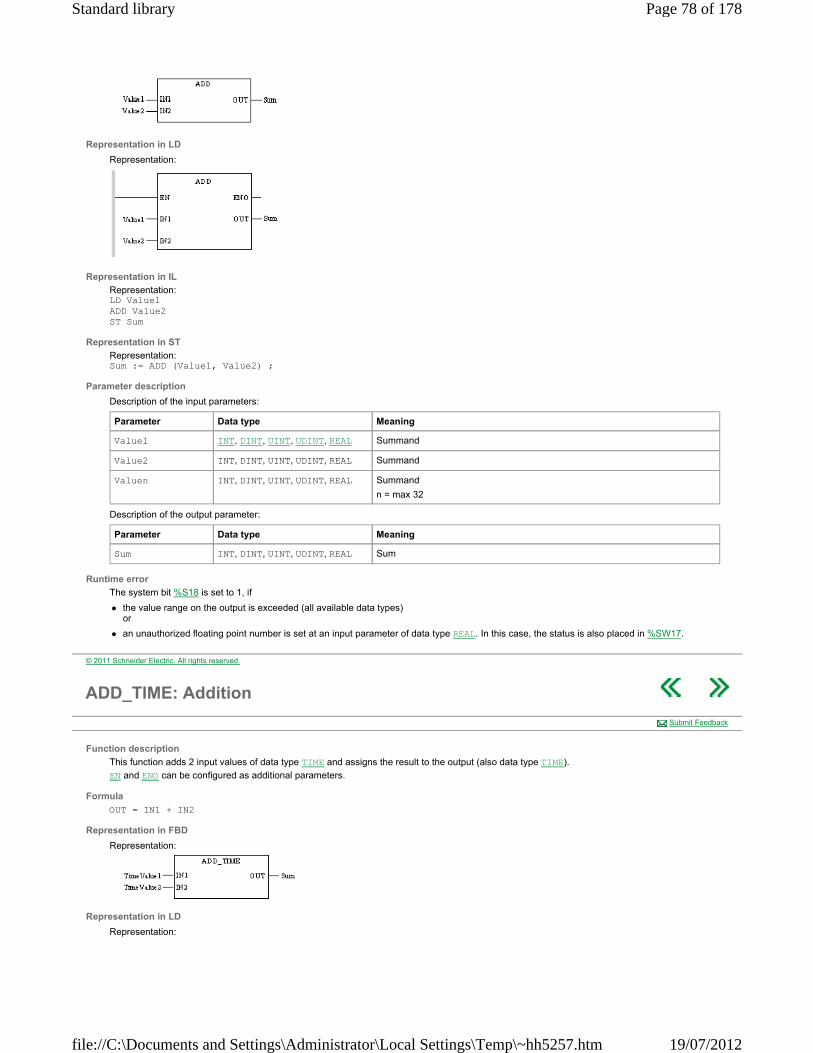
Representation in LD
Representation:
Representation in IL
Representation: LD Value1 ADD Value2 ST Sum
Representation in ST
Representation: Sum := ADD (Value1, Value2) ;
Parameter description
Description of the input parameters:
Description of the output parameter:
Runtime error
The system bit %S18 is set to 1, if
the value range on the output is exceeded (all available data types) or
an unauthorized floating point number is set at an input parameter of data type REAL. In this case, the status is also placed in %SW17.
Parameter Data type Meaning
Value1 INT, DINT, UINT, UDINT, REAL Summand
Value2 INT, DINT, UINT, UDINT, REAL Summand
Valuen INT, DINT, UINT, UDINT, REAL Summand
n = max 32
Parameter Data type Meaning
Sum INT, DINT, UINT, UDINT, REAL Sum
© 2011 Schneider Electric. All rights reserved.
ADD_TIME: Addition
Function description
This function adds 2 input values of data type TIME and assigns the result to the output (also data type TIME).
EN and ENO can be configured as additional parameters.
Formula
OUT = IN1 + IN2
Representation in FBD
Representation:
Representation in LD
Representation:
Submit Feedback
Page 78 of 178Standard library
19/07/2012file://C:\Documents and Settings\Administrator\Local Settings\Temp\~hh5257.htm

Representation in IL
Representation: LD TimeValue1 ADD_TIME TimeValue2 ST Sum
Representation in ST
Representation: Sum := ADD_TIME (TimeValue1, TimeValue2) ;
Parameter description
Description of the input parameters:
Description of the output parameter:
Runtime error
System bit %S18 is set to 1 if the value range at the output is exceeded.
Parameter Data type Meaning
TimeValue1 TIME Summand
TimeValue2 TIME Summand
Parameter Data type Meaning
Sum TIME Sum
© 2011 Schneider Electric. All rights reserved.
ASIN: Arc sine
Function description
The ASIN function calculates the principal sine arc of a real value. The result is given in the form of an angle in radians.
The function call can also be carried out by ASIN_REAL.
The additional parameters EN and ENO can be configured.
Formula
The formula is as follows:
Representation in FBD
Representation:
Representation in LD
Representation:
Representation in IL
Representation: LD Sin_Value ASIN_REAL ST Angle
Submit Feedback
Page 79 of 178Standard library
19/07/2012file://C:\Documents and Settings\Administrator\Local Settings\Temp\~hh5257.htm

Representation in ST
Representation: Angle:= ASIN_REAL(Sin_Value);
Description of parameters
The following table describes the input parameters:
The following table describes the output parameters:
Runtime errors
When the absolute value Sin_Value is greater than 1, the system bit %S18 changes to 1 and the system word %SW17 indicates the type of fault.
Parameter Type Comment
Sin_Value REAL Sine of angle calculated at block output.
-1 ≤ Sin_Value ≤ 1
Parameter Type Comment
Angle REAL Angle expressed in radians, whose sine has the value Sin_Value.
- π/2 ≤ Angle ≤ + π/2
© 2011 Schneider Electric. All rights reserved.
ATAN: Arc tangent
Function description
The ACOS function calculates the principal arc tangent of a real value. The result is given in the form of an angle in radians.
The function call can also be carried out by ATAN_REAL.
The additional parameters EN and ENO can be configured.
Formula
The formula is as follows:
Representation in FBD
Representation:
Representation in LD
Representation:
Representation in IL
Representation: LD Tan_Value ATAN_REAL ST Angle
Representation in ST
Representation: Angle:= ATAN_REAL(Tan_Value);
Description of parameters
The following table describes the input parameters:
The following table describes the output parameters:
Submit Feedback
Parameter Type Comment
Tan_Value REAL Tangent of angle calculated at block output.
-1.#INF < Tan_Value < +1.#INF
Page 80 of 178Standard library
19/07/2012file://C:\Documents and Settings\Administrator\Local Settings\Temp\~hh5257.htm
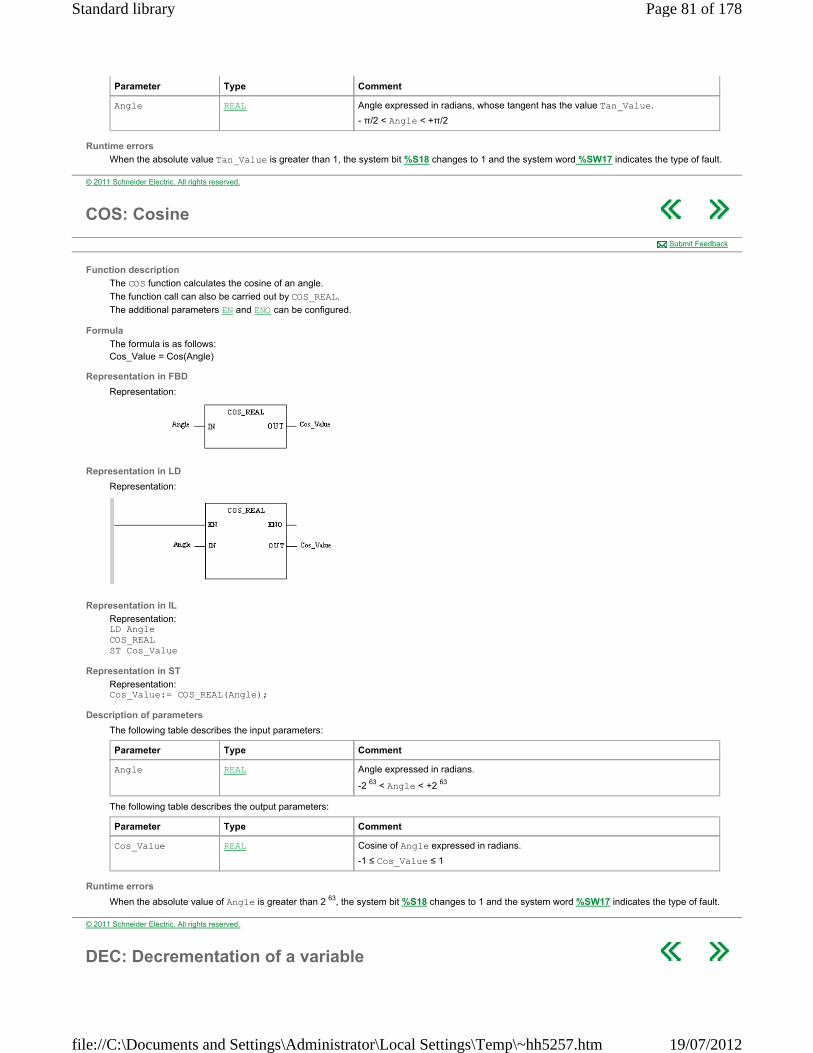
Runtime errors
When the absolute value Tan_Value is greater than 1, the system bit %S18 changes to 1 and the system word %SW17 indicates the type of fault.
Parameter Type Comment
Angle REAL Angle expressed in radians, whose tangent has the value Tan_Value.
- π/2 < Angle < +π/2
© 2011 Schneider Electric. All rights reserved.
COS: Cosine
Function description
The COS function calculates the cosine of an angle.
The function call can also be carried out by COS_REAL.
The additional parameters EN and ENO can be configured.
Formula
The formula is as follows: Cos_Value = Cos(Angle)
Representation in FBD
Representation:
Representation in LD
Representation:
Representation in IL
Representation: LD Angle COS_REAL ST Cos_Value
Representation in ST
Representation: Cos_Value:= COS_REAL(Angle);
Description of parameters
The following table describes the input parameters:
The following table describes the output parameters:
Runtime errors
When the absolute value of Angle is greater than 2 63, the system bit %S18 changes to 1 and the system word %SW17 indicates the type of fault.
Submit Feedback
Parameter Type Comment
Angle REAL Angle expressed in radians.
-2 63 < Angle < +2 63
Parameter Type Comment
Cos_Value REAL Cosine of Angle expressed in radians.
-1 ≤ Cos_Value ≤ 1
© 2011 Schneider Electric. All rights reserved.
DEC: Decrementation of a variable
Page 81 of 178Standard library
19/07/2012file://C:\Documents and Settings\Administrator\Local Settings\Temp\~hh5257.htm

Function description
The DEC function decrements a variable by 1.
The parameter of this function can be declared of type ANY_INT.
The additional parameters EN and ENO can be configured.
Representation in FBD
Representation applied to an integer:
Representation in LD
Representation applied to an integer:
Representation in IL
Representation applied to an integer: CAL DEC(Value1)
Representation in ST
Representation applied to an integer: DEC(Value1);
Description of parameters
The following table describes the input/output parameters:
Runtime errors
In the case of overrun, the system bit %S18 is set to 1 and the decremented value becomes positive (32767 for an integer for example).
Submit Feedback
Parameter Type Comment
Value1 INT, DINT, UINT, UDINT. Each time the program uses this EF the variable Value1 is decremented by one unit.
© 2011 Schneider Electric. All rights reserved.
DIV: Division
Function description
The function divides the value at the Dividend with the value at the Divisor input and assigns the result to the output.
The data types of the input values and the output values must be identical. For division with values of the TIME data type, you can use the block DIVTIME.
When dividing INT, DINT, UINT and UDINT data types, any decimal places in the result are omitted, e.g.
EN and ENO can be configured as additional parameters.
Formula
Representation in FBD
Representation:
Representation in LD
Representation:
Submit Feedback
Page 82 of 178Standard library
19/07/2012file://C:\Documents and Settings\Administrator\Local Settings\Temp\~hh5257.htm

Representation in IL
Representation: LD Dividend DIV Divisor ST Quotient
Representation in ST
Representation: Quotient := DIV (Dividend, Divisor) ;
Parameter description
Description of the input parameters:
Description of the output parameter:
Runtime error
The system bit %S18 is set to 1, if
an invalid division by 0 is executed (all available data types) or
an unauthorized floating point number is set at an input parameter of data type REAL. In this case, the status is also placed in %SW17.
Parameter Data type Meaning
Dividend INT, DINT, UINT, UDINT, REAL Dividend
Divisor INT, DINT, UINT, UDINT, REAL Divisor
Parameter Data type Meaning
Quotient INT, DINT, UINT, UDINT, REAL Quotient
© 2011 Schneider Electric. All rights reserved.
DIVMOD: Division and Modulo
Function description
This procedure divides the value at the Dividend input by the value at the Divisor input. The result of the division is delivered at the Quotient output. The remainder of the division is delivered at the Modulo output.
If there is a decimal place in the division result, the division will truncate it. The data types of all input and output values must be identical. EN and ENO can be configured as additional parameters.
Formula
Block formula: DV = IN1 / IN2
MD = IN1 mod IN2
Representation in FBD
Representation:
Representation in LD
Representation:
Submit Feedback
Page 83 of 178Standard library
19/07/2012file://C:\Documents and Settings\Administrator\Local Settings\Temp\~hh5257.htm

Representation in IL
Representation: LD Dividend DIVMOD Divisor, Quotient, Modulo
Representation in ST
Representation: DIVMOD (Dividend, Divisor, Quotient, Modulo);
Parameter description
Description of the input parameters:
Description of the output parameter:
Runtime error
The system bit %S18 is set to 1, if an invalid division by 0 is executed.
Parameter Data type Meaning
Dividend INT, DINT, UINT, UDINT Dividend
Divisor INT, DINT, UINT, UDINT Divisor
Parameter Data type Meaning
Quotient INT, DINT, UINT, UDINT Quotient
Modulo INT, DINT, UINT, UDINT Modulo
© 2011 Schneider Electric. All rights reserved.
EXP: Natural exponential
Function description
The EXP function calculates the natural exponential of a real.
The function call can also be carried out by EXP_REAL.
The additional parameters EN and ENO can be configured.
Formula
The formula is as follows:
Representation in FBD
Representation:
Representation in LD
Representation:
Representation in IL
Representation: LD Real_Value EXP_REAL ST Exp_Real_Value
Representation in ST
Representation: Log_Real_Value:= EXP_REAL(Real_Value);
Description of parameters
The following table describes the input parameters:
Submit Feedback
Parameter Type Comment
Page 84 of 178Standard library
19/07/2012file://C:\Documents and Settings\Administrator\Local Settings\Temp\~hh5257.htm

The following table describes the output parameters:
Runtime errors
When Real_Value is situated outside the interval ]-87.33654, 88.72283[, the system bit %S18 changes to 1 and the system word %SW17 indicates the type of fault.
Real_Value REAL Real value of which we wish to obtain the Natural exponential
-87.33654 < Real_Value < 88.72283
Parameter Type Comment
Exp_Real_Value REAL Natural exponential of Real_Value
0 < Exp_Real_Value < 1.#INF
© 2011 Schneider Electric. All rights reserved.
EXPT_REAL_***: Exponentiation of one value by another value
Function Description
The EXPT_REAL_*** function calculates the exponentiation of one value by another value.
The additional parameters EN and ENO can be configured.
Available functions
The available functions are as follows:
EXPT_REAL_INT, EXPT_REAL_DINT, EXPT_REAL_UINT, EXPT_REAL_UDINT, EXPT_REAL_REAL.
Formula
The formula is as follows:
Representation in FBD
Representation applied to a real number:
Representation in LD
Representation applied to a real number:
Representation in IL
Representation applied to a real number: LD Value1 EXPT_REAL_REAL Exponent ST Expt_Real_Value
Representation in ST
Representation applied to a real number: Expt_Real_Value := EXPT_REAL_REAL(Value1, Exponent);
Description of parameters
The following table describes the input parameters:
Submit Feedback
Parameter Type Comment
Value1 REAL Value for which you want to find the exponential by Exponent
0 ≤ Value1 < INF
Exponent INT,
UINT,
Exponent of the exponential
-INF < Exponent < +INF
Page 85 of 178Standard library
19/07/2012file://C:\Documents and Settings\Administrator\Local Settings\Temp\~hh5257.htm
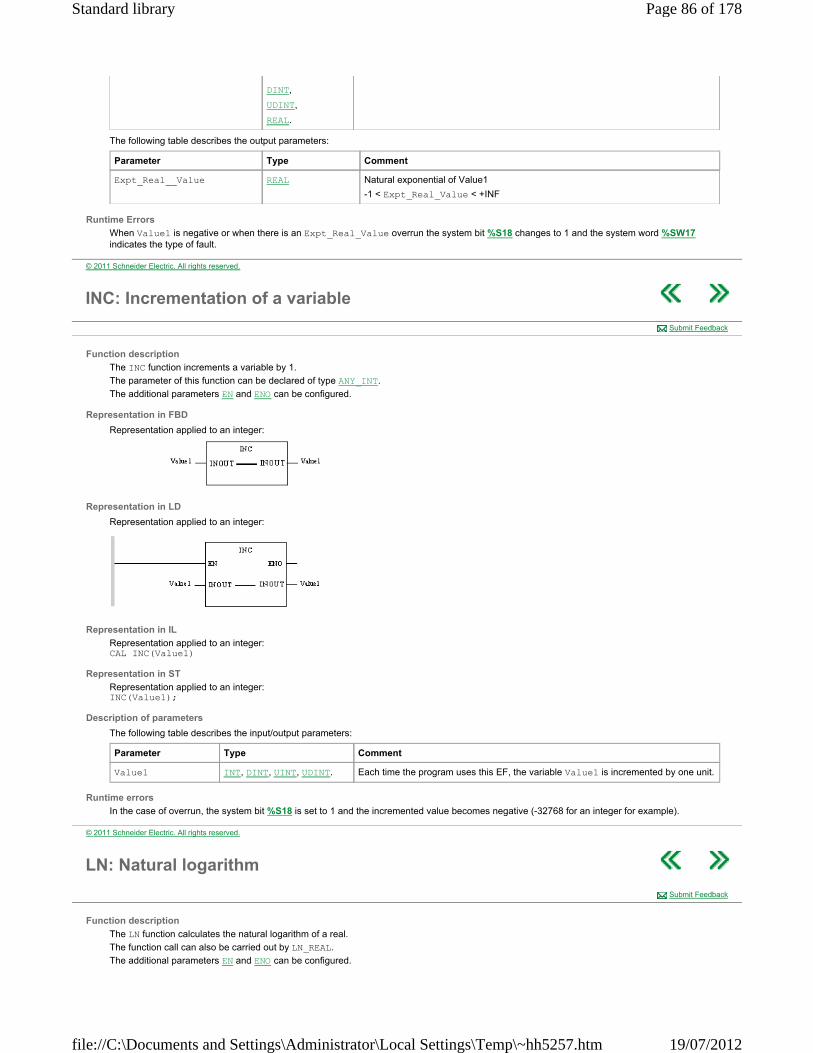
The following table describes the output parameters:
Runtime Errors
When Value1 is negative or when there is an Expt_Real_Value overrun the system bit %S18 changes to 1 and the system word %SW17 indicates the type of fault.
DINT,
UDINT,
REAL.
Parameter Type Comment
Expt_Real__Value REAL Natural exponential of Value1
-1 < Expt_Real_Value < +INF
© 2011 Schneider Electric. All rights reserved.
INC: Incrementation of a variable
Function description
The INC function increments a variable by 1.
The parameter of this function can be declared of type ANY_INT.
The additional parameters EN and ENO can be configured.
Representation in FBD
Representation applied to an integer:
Representation in LD
Representation applied to an integer:
Representation in IL
Representation applied to an integer: CAL INC(Value1)
Representation in ST
Representation applied to an integer: INC(Value1);
Description of parameters
The following table describes the input/output parameters:
Runtime errors
In the case of overrun, the system bit %S18 is set to 1 and the incremented value becomes negative (-32768 for an integer for example).
Submit Feedback
Parameter Type Comment
Value1 INT, DINT, UINT, UDINT. Each time the program uses this EF, the variable Value1 is incremented by one unit.
© 2011 Schneider Electric. All rights reserved.
LN: Natural logarithm
Function description
The LN function calculates the natural logarithm of a real.
The function call can also be carried out by LN_REAL.
The additional parameters EN and ENO can be configured.
Submit Feedback
Page 86 of 178Standard library
19/07/2012file://C:\Documents and Settings\Administrator\Local Settings\Temp\~hh5257.htm
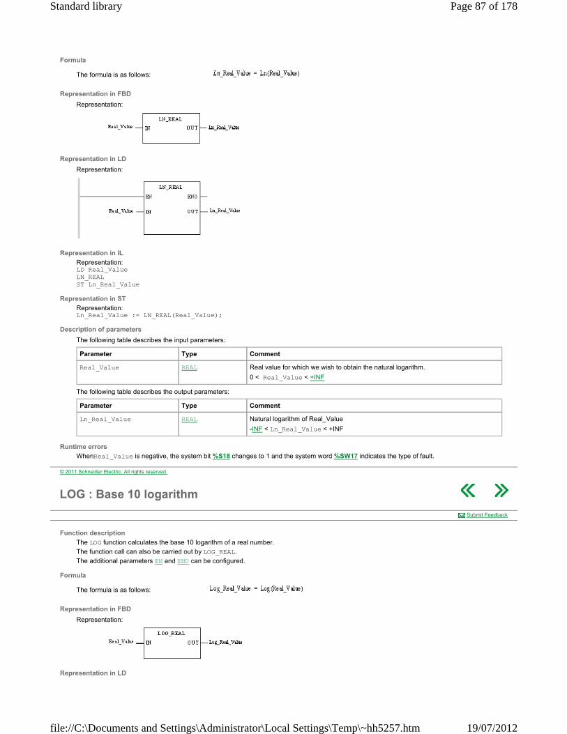
Formula
The formula is as follows:
Representation in FBD
Representation:
Representation in LD
Representation:
Representation in IL
Representation: LD Real_Value LN_REAL ST Ln_Real_Value
Representation in ST
Representation: Ln_Real_Value := LN_REAL(Real_Value);
Description of parameters
The following table describes the input parameters:
The following table describes the output parameters:
Runtime errors
WhenReal_Value is negative, the system bit %S18 changes to 1 and the system word %SW17 indicates the type of fault.
Parameter Type Comment
Real_Value REAL Real value for which we wish to obtain the natural logarithm.
0 < Real_Value < +INF
Parameter Type Comment
Ln_Real_Value REAL Natural logarithm of Real_Value
-INF < Ln_Real_Value < +INF
© 2011 Schneider Electric. All rights reserved.
LOG : Base 10 logarithm
Function description
The LOG function calculates the base 10 logarithm of a real number.
The function call can also be carried out by LOG_REAL.
The additional parameters EN and ENO can be configured.
Formula
The formula is as follows:
Representation in FBD
Representation:
Representation in LD
Submit Feedback
Page 87 of 178Standard library
19/07/2012file://C:\Documents and Settings\Administrator\Local Settings\Temp\~hh5257.htm

Representation:
Representation in IL
Representation: LD Real_Value LOG_REAL ST Log_Real_Value
Representation in ST
Representation: Log_Real_Value:= LOG_REAL(Real_Value);
Description of parameters
The following table describes the input parameters:
The following table describes the output parameters:
Runtime errors
WhenReal_Value is negative, the system bit %S18 changes to 1 and the system word %SW17 indicates the type of fault.
Parameter Type Comment
Real_Value REAL Real value of which we wish to obtain the natural logarithm.
0 < Real_Value < 1.#INF
Parameter Type Comment
Log_Real_Value REAL Natural logarithm of Real_Value
-1.#INF < Log_Real_Value < +1.#INF
© 2011 Schneider Electric. All rights reserved.
MOD: Modulo
Function description
The function divides the value at the Dividend with the value at the Divisor input and assigns the modulo to the output.
The data types of all input values and output values must be identical. EN and ENO can be configured as additional parameters.
Formula
OUT = IN1 mod IN2
Representation in FBD
Representation:
Representation in LD
Representation:
Representation in IL
Representation: LD Dividend MOD Divisor ST Rest
Submit Feedback
Page 88 of 178Standard library
19/07/2012file://C:\Documents and Settings\Administrator\Local Settings\Temp\~hh5257.htm
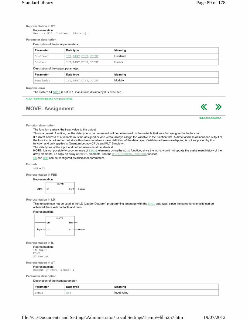
Representation in ST
Representation: Rest := MOD (Dividend, Divisor) ;
Parameter description
Description of the input parameters:
Description of the output parameter:
Runtime error
The system bit %S18 is set to 1, if an invalid division by 0 is executed.
Parameter Data type Meaning
Dividend INT, DINT, UINT, UDINT Dividend
Divisor INT, DINT, UINT, UDINT Divisor
Parameter Data type Meaning
Remainder INT, DINT, UINT, UDINT Modulo
© 2011 Schneider Electric. All rights reserved.
MOVE: Assignment
Function description
The function assigns the input value to the output. This is a generic function, i.e. the data type to be processed will be determined by the variable that was first assigned to the function. If a direct address of a variable must be assigned or vice versa, always assign the variable to the function first. A direct address at input and output of the function is not authorized since this does not allow a clear definition of the data type. Variables address overlapping is not supported by this function and only applies to Quantum Legacy CPUs and PLC Simulator. The data types of the input and output values must be identical. NOTE: It is not possible to copy an array of EBOOL elements using the MOVE function, since the MOVE would not update the assignment history of the array elements. To copy an array of EBOOL elements, use the COPY_AREBOOL_AREBOOL function.
EN and ENO can be configured as additional parameters.
Formula
OUT = IN
Representation in FBD
Representation:
Representation in LD
This function can not be used in the LD (Ladder Diagram) programming language with the BOOL data type, since the same functionality can be achieved there with contacts and coils.
Representation:
Representation in IL
Representation: LD Input MOVE ST Output
Representation in ST
Representation: Output := MOVE (Input) ;
Parameter description
Description of the input parameter:
Submit Feedback
Parameter Data type Meaning
Input ANY Input value
Page 89 of 178Standard library
19/07/2012file://C:\Documents and Settings\Administrator\Local Settings\Temp\~hh5257.htm
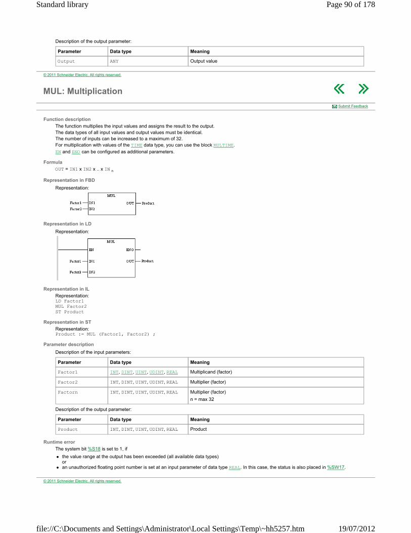
Description of the output parameter:
Parameter Data type Meaning
Output ANY Output value
© 2011 Schneider Electric. All rights reserved.
MUL: Multiplication
Function description
The function multiplies the input values and assigns the result to the output. The data types of all input values and output values must be identical. The number of inputs can be increased to a maximum of 32. For multiplication with values of the TIME data type, you can use the block MULTIME.
EN and ENO can be configured as additional parameters.
Formula
OUT = IN1 x IN2 x .. x IN n
Representation in FBD
Representation:
Representation in LD
Representation:
Representation in IL
Representation: LD Factor1 MUL Factor2 ST Product
Representation in ST
Representation: Product := MUL (Factor1, Factor2) ;
Parameter description
Description of the input parameters:
Description of the output parameter:
Runtime error
The system bit %S18 is set to 1, if
the value range at the output has been exceeded (all available data types) or
an unauthorized floating point number is set at an input parameter of data type REAL. In this case, the status is also placed in %SW17.
Submit Feedback
Parameter Data type Meaning
Factor1 INT, DINT, UINT, UDINT, REAL Multiplicand (factor)
Factor2 INT, DINT, UINT, UDINT, REAL Multiplier (factor)
Factorn INT, DINT, UINT, UDINT, REAL Multiplier (factor)
n = max 32
Parameter Data type Meaning
Product INT, DINT, UINT, UDINT, REAL Product
© 2011 Schneider Electric. All rights reserved.
Page 90 of 178Standard library
19/07/2012file://C:\Documents and Settings\Administrator\Local Settings\Temp\~hh5257.htm
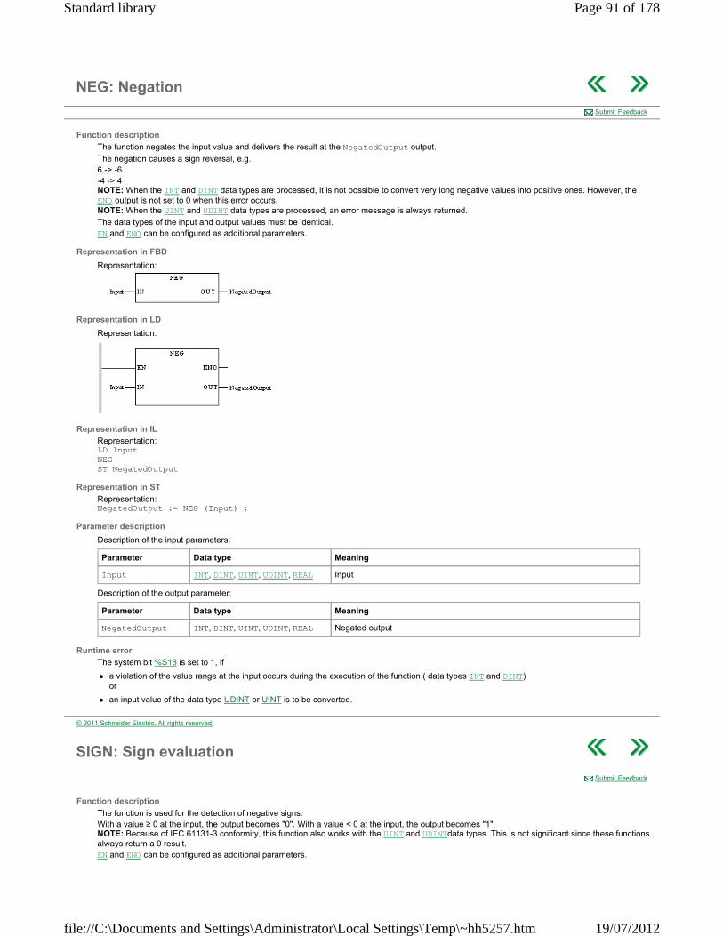
NEG: Negation
Function description
The function negates the input value and delivers the result at the NegatedOutput output.
The negation causes a sign reversal, e.g. 6 -> -6 -4 -> 4 NOTE: When the INT and DINT data types are processed, it is not possible to convert very long negative values into positive ones. However, the ENO output is not set to 0 when this error occurs. NOTE: When the UINT and UDINT data types are processed, an error message is always returned.
The data types of the input and output values must be identical. EN and ENO can be configured as additional parameters.
Representation in FBD
Representation:
Representation in LD
Representation:
Representation in IL
Representation: LD Input NEG ST NegatedOutput
Representation in ST
Representation: NegatedOutput := NEG (Input) ;
Parameter description
Description of the input parameters:
Description of the output parameter:
Runtime error
The system bit %S18 is set to 1, if
a violation of the value range at the input occurs during the execution of the function ( data types INT and DINT) or
an input value of the data type UDINT or UINT is to be converted.
Submit Feedback
Parameter Data type Meaning
Input INT, DINT, UINT, UDINT, REAL Input
Parameter Data type Meaning
NegatedOutput INT, DINT, UINT, UDINT, REAL Negated output
© 2011 Schneider Electric. All rights reserved.
SIGN: Sign evaluation
Function description
The function is used for the detection of negative signs. With a value ≥ 0 at the input, the output becomes "0". With a value < 0 at the input, the output becomes "1". NOTE: Because of IEC 61131-3 conformity, this function also works with the UINT and UDINTdata types. This is not significant since these functions always return a 0 result. EN and ENO can be configured as additional parameters.
Submit Feedback
Page 91 of 178Standard library
19/07/2012file://C:\Documents and Settings\Administrator\Local Settings\Temp\~hh5257.htm

Formula
Block formula: OUT = 1, if IN < 0
OUT = 0, if IN ≥ 0 NOTE: Because of the different processing of REAL and INT values, the following behavior results for signed 0 (+/-0): -0.0 -> SIGN_REAL -> 1 +0.0 -> SIGN_REAL -> 0 -0 -> SIGN_INT/DINT -> 0 +0 -> SIGN_INT/DINT -> 0
Representation in FBD
Representation:
Representation in LD
Representation:
Representation in IL
Representation: LD Value SIGN ST Negativ
Representation in ST
Representation: Negativ := SIGN (Value) ;
Parameter description
Description of input parameters:
Description of output parameters:
Runtime error
The system bit %S18 is set to 1 and ENO to 0 if
an input value of the data type UINT or UDINT is to set.
Parameter Data type Meaning
Value INT, DINT, REAL Signed input
Parameter Data type Meaning
Negative BOOL Sign evaluation
© 2011 Schneider Electric. All rights reserved.
SIN: Sine
Function description
The SIN function calculates the sine of an angle.
The function call can also be carried out by SIN_REAL.
The additional parameters EN and ENO can be configured.
Formula
The formula is as follows: Sin_Value = Sin(Angle)
Representation in FBD
Representation:
Submit Feedback
Page 92 of 178Standard library
19/07/2012file://C:\Documents and Settings\Administrator\Local Settings\Temp\~hh5257.htm
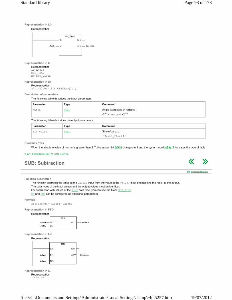
Representation in LD
Representation:
Representation in IL
Representation: LD Angle SIN_REAL ST Sin_Value
Representation in ST
Representation: Sin_Value:= SIN_REAL(Angle);
Description of parameters
The following table describes the input parameters:
The following table describes the output parameters:
Runtime errors
When the absolute value of Angle is greater than 2 63, the system bit %S18 changes to 1 and the system word %SW17 indicates the type of fault.
Parameter Type Comment
Angle REAL Angle expressed in radians.
-2 63 < Angle < +2 63
Parameter Type Comment
Sin_Value REAL Sine of Angle.
-1 ≤ Sin_Value ≤ 1
© 2011 Schneider Electric. All rights reserved.
SUB: Subtraction
Function description
The function subtracts the value at the Value2 input from the value at the Value1 input and assigns the result to the output.
The data types of the input values and the output values must be identical. For subtraction with values of the TIME data type, you can use the block SUB_TIME.
EN and ENO can be configured as additional parameters.
Formula
Difference = Value1 - Value2
Representation in FBD
Representation:
Representation in LD
Representation:
Representation in IL
Representation: LD Value1
Submit Feedback
Page 93 of 178Standard library
19/07/2012file://C:\Documents and Settings\Administrator\Local Settings\Temp\~hh5257.htm
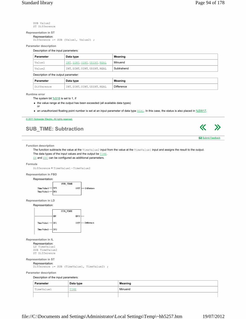
SUB Value2 ST Difference
Representation in ST
Representation: Difference := SUB (Value1, Value2) ;
Parameter description
Description of the input parameters:
Description of the output parameter:
Runtime error
The system bit %S18 is set to 1, if
the value range at the output has been exceeded (all available data types) or
an unauthorized floating point number is set at an input parameter of data type REAL. In this case, the status is also placed in %SW17.
Parameter Data type Meaning
Value1 INT, DINT, UINT, UDINT, REAL Minuend
Value2 INT, DINT, UINT, UDINT, REAL Subtrahend
Parameter Data type Meaning
Difference INT, DINT, UINT, UDINT, REAL Difference
© 2011 Schneider Electric. All rights reserved.
SUB_TIME: Subtraction
Function description
The function subtracts the value at the TimeValue2 input from the value at the TimeValue1 input and assigns the result to the output.
The data types of the input values and the output be TIME.
EN and ENO can be configured as additional parameters.
Formula
Difference = TimeValue1 - TimeValue2
Representation in FBD
Representation:
Representation in LD
Representation:
Representation in IL
Representation: LD TimeValue1 SUB TimeValue2 ST Difference
Representation in ST
Representation: Difference := SUB (TimeValue1, TimeValue2) ;
Parameter description
Description of the input parameters:
Submit Feedback
Parameter Data type Meaning
TimeValue1 TIME Minuend
Page 94 of 178Standard library
19/07/2012file://C:\Documents and Settings\Administrator\Local Settings\Temp\~hh5257.htm
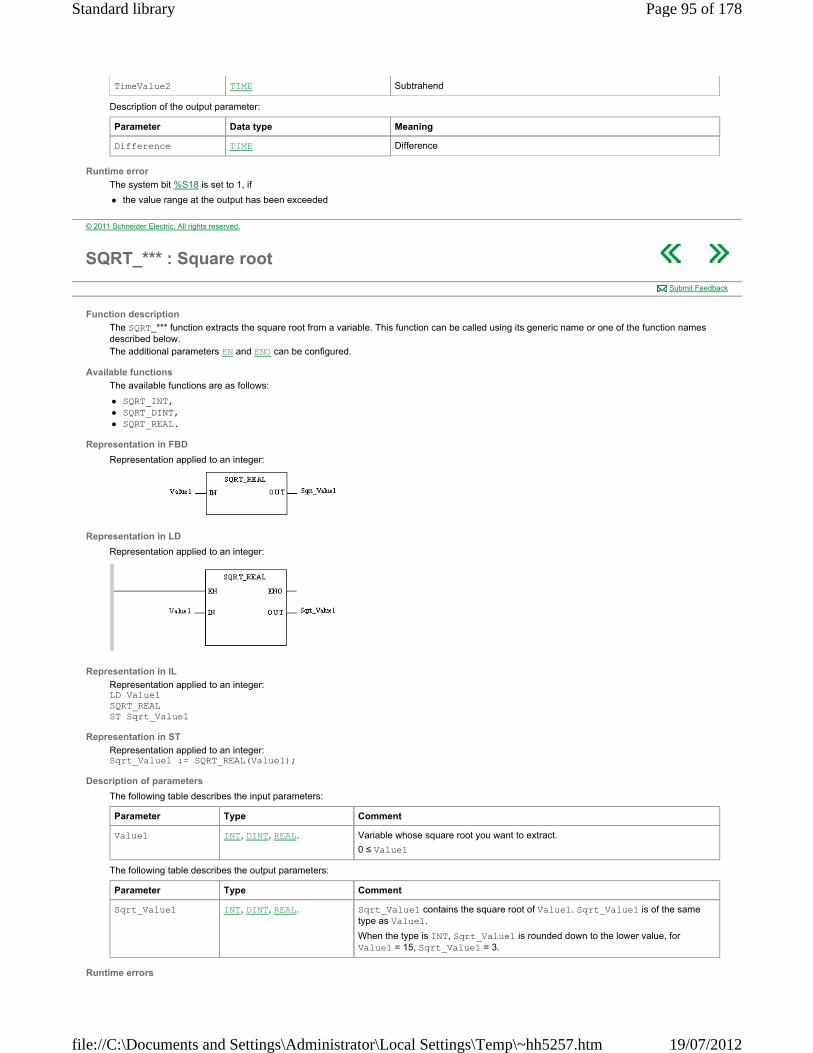
Description of the output parameter:
Runtime error
The system bit %S18 is set to 1, if
the value range at the output has been exceeded
TimeValue2 TIME Subtrahend
Parameter Data type Meaning
Difference TIME Difference
© 2011 Schneider Electric. All rights reserved.
SQRT_*** : Square root
Function description
The SQRT_*** function extracts the square root from a variable. This function can be called using its generic name or one of the function names described below. The additional parameters EN and ENO can be configured.
Available functions
The available functions are as follows:
SQRT_INT, SQRT_DINT, SQRT_REAL.
Representation in FBD
Representation applied to an integer:
Representation in LD
Representation applied to an integer:
Representation in IL
Representation applied to an integer: LD Value1 SQRT_REAL ST Sqrt_Value1
Representation in ST
Representation applied to an integer: Sqrt_Value1 := SQRT_REAL(Value1);
Description of parameters
The following table describes the input parameters:
The following table describes the output parameters:
Runtime errors
Submit Feedback
Parameter Type Comment
Value1 INT, DINT, REAL. Variable whose square root you want to extract.
0 ≤ Value1
Parameter Type Comment
Sqrt_Value1 INT, DINT, REAL. Sqrt_Value1 contains the square root of Value1. Sqrt_Value1 is of the same type as Value1.
When the type is INT, Sqrt_Value1 is rounded down to the lower value, for Value1 = 15, Sqrt_Value1 = 3.
Page 95 of 178Standard library
19/07/2012file://C:\Documents and Settings\Administrator\Local Settings\Temp\~hh5257.htm

When Value1 is of REAL type and negative, the result of the function contains -1.#NAN and bit %S18 = 1.
When Value1 is of INT or DINT type and negative, the result of the function contains the negative value Value1 and bit %S18 = 1.
In case of %S18 = 1 the system word %SW17 indicates the type of fault.
© 2011 Schneider Electric. All rights reserved.
TAN: Tangent
Function description
The TAN function calculates the tangent of an angle.
The function call can also be carried out by TAN_REAL.
The additional parameters EN and ENO can be configured.
Formula
The formula is as follows:
Representation in FBD
Representation:
Representation in LD
Representation:
Representation in IL
Representation: LD Angle TAN_REAL ST Tan_Value
Representation in ST
Representation: Tan_Value:= TAN_REAL(Angle);
Description of parameters
The following table describes the input parameters:
The following table describes the output parameters:
Runtime errors
When the absolute value of Angle is greater than 2 63, the system bit %S18 changes to 1 and the system word %SW17 indicates the type of fault.
Submit Feedback
Parameter Type Comment
Angle REAL Angle expressed in radians.
-2 63 < Angle < +2 63
Parameter Type Comment
Tan_Value REAL Tangent of Angle
-1.#INF < Tan_Value < +1.#INF
© 2011 Schneider Electric. All rights reserved.
Statistical
Overview
This section describes the elementary functions and elementary function blocks of the Statistical group.
Page 96 of 178Standard library
19/07/2012file://C:\Documents and Settings\Administrator\Local Settings\Temp\~hh5257.htm
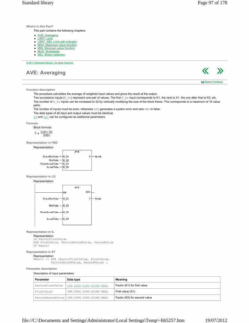
What's in this Part?
This part contains the following chapters:
AVE: Averaging LIMIT: Limit LIMIT_IND: Limit with indicator MAX: Maximum value function MIN: Minimum value function MUX: Multiplexer SEL: Binary selection
© 2011 Schneider Electric. All rights reserved.
AVE: Averaging
Function description
The procedure calculates the average of weighted input values and gives the result at the output. Two successive inputs (K_Xn) represent one pair of values. The first K_Xn input corresponds to K1, the next to X1, the one after that to K2, etc.
The number of K_Xn inputs can be increased to 32 by vertically modifying the size of the block frame. This corresponds to a maximum of 16 value pairs. The number of inputs must be even, otherwise AVE generates a system error and sets ENO to false.
The data types of all input and output values must be identical. EN and ENO can be configured as additional parameters.
Formula
Block formula:
Representation in FBD
Representation:
Representation in LD
Representation:
Representation in IL
Representation: LD FactorFirstValue AVE FirstValue, FactorSecondValue, SecondValue ST Result
Representation in ST
Representation: Result := AVE (FactorFirstValue, FirstValue, FactorSecondValue, SecondValue) ;
Parameter description
Description of input parameters:
Submit Feedback
Parameter Data type Meaning
FactorFirstValue INT, DINT, UINT, UDINT, REAL Factor (K1) for first value
FirstValue INT, DINT, UINT, UDINT, REAL First value (X1)
FactorSecondValue INT, DINT, UINT, UDINT, REAL Factor (K2) for second value
Page 97 of 178Standard library
19/07/2012file://C:\Documents and Settings\Administrator\Local Settings\Temp\~hh5257.htm

Description of output parameters:
Runtime error
The system bit %S18 is set to 1, if
the value range of the output is exceeded (all available data types) or
an invalid division by 0 is executed (all available data types) or
an unauthorized floating point number is set at an input parameter of data type REAL. In this case, the status is also placed in %SW17. Note: %SW17.1 (Denormalized operand / result is acceptable) flag is not managed by AVE procedure.
NOTE: For a list of all block error codes and values, see Statistical.
FactorSecondValue INT, DINT, UINT, UDINT, REAL Second value (X2)
:
FactorHalfnValue INT, DINT, UINT, UDINT, REAL Factor for value of (K_X(n-1))
HalfnValue INT, DINT, UINT, UDINT, REAL Value of (K_X(n)
n = max 32
Parameter Data type Meaning
Result INT, DINT, UINT, UDINT, REAL Average value
© 2011 Schneider Electric. All rights reserved.
LIMIT: Limit
Function description
This function transfers the unchanged input value (Input) to the output if the input value is not less than the minimum value (LowerLimit) and does not exceed the maximum value (UpperLimit). If the input value (Input) is less than the minimum value (LowerLimit), the minimum value will be transferred to the output. If the input value (Input) exceeds the maximum value (UpperLimit), the maximum value will be transferred to the output. The data types of all input values and output values must be identical. EN and ENO can be configured as additional parameters.
Formula
OUT = IN, if (IN ≥ MN) & (IN ≤ MX)
OUT = MN, if (IN < MN)
OUT = MX, if (IN > MX)
Representation in FBD
Representation:
Representation in LD
Representation:
Representation in IL
Representation: LD LowerLimit LIMIT Input, UpperLimit ST Output
Representation in ST
Submit Feedback
Page 98 of 178Standard library
19/07/2012file://C:\Documents and Settings\Administrator\Local Settings\Temp\~hh5257.htm

Representation: Output := LIMIT (LowerLimit, Input, UpperLimit) ;
Parameter description
Description of the input parameters:
Description of the output parameter:
Runtime error
If there is an unauthorized floating point number at the input, an error message is returned.
Parameter Data type Meaning
MN BOOL, BYTE, WORD, DWORD, INT, DINT, UINT, UDINT, REAL, TIME
Lower limit
IN BOOL, BYTE, WORD, DWORD, INT, DINT, UINT, UDINT, REAL, TIME
Input
MX BOOL, BYTE, WORD, DWORD, INT, DINT, UINT, UDINT, REAL, TIME
Upper limit
Parameter Data type Meaning
OUT BOOL, BYTE, WORD, DWORD, INT, DINT, UINT, UDINT, REAL, TIME
Output
© 2011 Schneider Electric. All rights reserved.
LIMIT_IND: Limit with indicator
Function description
This procedure transfers the unchanged input value (Input) to the (Output), if the input value is not less than the minimum value (LimitMinimum) and does not exceed the maximum value (LimitMaximum). If the input value (Input) is less than the minimum value (LimitMinimum), the minimum value will be transferred to the output. If the input value (Input) exceeds the maximum value (LimitMaximum), the maximum value will be transferred to the output. Additionally, a indication is given if the minimum or maximum value is violated. If the value at the (Input) input is less than the value at the (LimitMinimum) input, the (MinimumViolation) output becomes "1". If the value at the (Input) input is more than the value at the (LimitMaximum) input, the (MaximumViolation) output becomes "1".
The data types of the (LimitMinimum, Input, LimitMaximum) input values and the (Output) output value must be identical.
EN and ENO can be configured as additional parameters.
Formula
Block formula: OUT = IN, if (IN ≤ MX) & IN ≥ MN
OUT = MN, if (IN < MN)
OUT = MX, if (IN > MX)
MN_IND = 0, if IN ≥ MN
MN_IND = 1, if IN < MN
MX_IND = 0, if IN ≤ MX
MX_IND = 1, if IN > MX
Representation in FBD
Representation:
Representation in LD
Representation:
Representation in IL
Submit Feedback
Page 99 of 178Standard library
19/07/2012file://C:\Documents and Settings\Administrator\Local Settings\Temp\~hh5257.htm

Representation: LD LimitMinimum LIMIT_IND Input, LimitMaximum, MinimumViolation, Output, MaximumViolation
Representation in ST
Representation: LIMIT_IND (LimitMinimum, Input, LimitMaximum, MinimumViolation, Output, MaximumViolation);
Parameter description
Description of the input parameters:
Description of the output parameter:
Parameter Data type Meaning
LimitMinimum BOOL, BYTE, WORD, DWORD, INT, DINT, UINT, UDINT, REAL, TIME
Limit of minimum value
Input BOOL, BYTE, WORD, DWORD, INT, DINT, UINT, UDINT, REAL, TIME
Input
LimitMaximum BOOL, BYTE, WORD, DWORD, INT, DINT, UINT, UDINT, REAL, TIME
Limit of maximum value
Parameter Data type Meaning
MinimumViolation BOOL Display of minimum value violation
Output BOOL, BYTE, WORD, DWORD, INT, DINT, UINT, UDINT, REAL, TIME
Output
MaximumViolation BOOL Display of maximum value violation
© 2011 Schneider Electric. All rights reserved.
MAX: Maximum value function
Function description
The function assigns the largest input value to the output. The data types of all input values and output values must be identical. The number of inputs can be increased. EN and ENO can be configured as additional parameters.
Formula
OUT = MAX {IN1, IN2, ..., INn}
Representation in FBD
Representation:
Representation in LD
Representation:
Representation in IL
Representation: LD Value1 MAX Value2 ST Maximum
Representation in ST
Representation: Maximum := MAX (Value1, Value2) ;
Parameter description
Submit Feedback
Page 100 of 178Standard library
19/07/2012file://C:\Documents and Settings\Administrator\Local Settings\Temp\~hh5257.htm

Description of input parameters:
Description of output parameters:
Runtime error
If an unauthorized floating point number is created for an input parameter of data type REAL, the system bit %S18 is set to 1 and the status is placed in %SW17. NOTE: For a list of all the block error messages and values, see Common Floating Point Errors.
Parameter Data type Meaning
Value1 BOOL, BYTE, WORD, DWORD, INT, DINT, UINT, UDINT, REAL, TIME
1. Input value
Value2 BOOL, BYTE, WORD, DWORD, INT, DINT, UINT, UDINT, REAL, TIME
2. Input value
Valuen BOOL, BYTE, WORD, DWORD, INT, DINT, UINT, UDINT, REAL, TIME
n. Input value
n = max 32
Parameter Data type Meaning
Maximum BOOL, BYTE, WORD, DWORD, INT, DINT, UINT, UDINT, REAL, TIME
Maximum value
© 2011 Schneider Electric. All rights reserved.
MIN: Minimum value function
Function description
The function assigns the smallest input value to the output. The data types of all input values and output values must be identical. The number of inputs can be increased. EN and ENO can be configured as additional parameters.
Formula
OUT = MIN {IN1, IN2, ..., INn}
Representation in FBD
Representation:
Representation in LD
Representation:
Representation in IL
Representation: LD Value1 MIN Value2 ST Minimum
Representation in ST
Representation: Minimum := MIN (Value1, Value2) ;
Parameter description
Description of input parameters:
Submit Feedback
Parameter Data type Meaning
Value1 BOOL, BYTE, WORD, DWORD, INT, DINT, UINT, UDINT, REAL, TIME
1. Input value
Value2 BOOL, BYTE, WORD, DWORD, INT, DINT, UINT, UDINT, REAL, TIME
2. Input value
Page 101 of 178Standard library
19/07/2012file://C:\Documents and Settings\Administrator\Local Settings\Temp\~hh5257.htm

Description of output parameters:
Runtime error
If an unauthorized floating point number is created for an input parameter of data type REAL, the system bit %S18 is set to 1 and the status is placed in %SW17. NOTE: For a list of all the block error messages and values, see Common Floating Point Errors.
Valuen BOOL, BYTE, WORD, DWORD, INT, DINT, UINT, UDINT, REAL, TIME
n. Input value
n = max 32
Parameter Data type Meaning
Minimum BOOL, BYTE, WORD, DWORD, INT, DINT, UINT, UDINT, REAL, TIME
Minimum value
© 2011 Schneider Electric. All rights reserved.
MUX: Multiplexer
Function description
This function transfers the respective input to the output depending on the value at the K input.
The number of inputs can be increased. EN and ENO can be configured as additional parameters.
Example
K = 0: Input IN0 is transferred to the output
K = 1: Input IN1 is transferred to the output
K = 5: Input IN5 is transferred to the output
K= n: Input INn is transferred to the output
Data types
The data types at the inputs Input0 to Inputn and at the output must be identical.
Representation in FBD
Representation:
Representation in LD
Representation:
Representation in IL
Representation: LD Selection MUX Input0, Input1 ST Output
Representation in ST
Representation: Output := MUX (Selection, Input0, Input1) ;
Parameter description
Description of input parameters:
Submit Feedback
Parameter Data type Meaning
K INT, DINT, UINT, UDINT Selection input
Page 102 of 178Standard library
19/07/2012file://C:\Documents and Settings\Administrator\Local Settings\Temp\~hh5257.htm
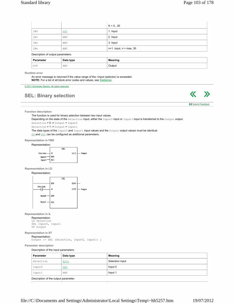
Description of output parameters:
Runtime error
An error message is returned if the value range of the Kinput (selector) is exceeded. NOTE: For a list of all block error codes and values, see Statistical.
K = 0...30
IN0 ANY 1. Input
IN1 ANY 2. Input
IN2 ANY 3. Input
INn ANY n+1. input, n = max. 30
Parameter Data type Meaning
OUT ANY Output
© 2011 Schneider Electric. All rights reserved.
SEL: Binary selection
Function description
The function is used for binary selection between two input values. Depending on the state of the Selection input, either the Input0 input or Input1 input is transferred to the Output output.
Selection = 0 -> Output = Input0
Selection = 1 -> Output = Input1
The data types of the Input0 and Input1 input values and the Output output values must be identical.
EN and ENO can be configured as additional parameters.
Representation in FBD
Representation:
Representation in LD
Representation:
Representation in IL
Representation: LD Selection SEL Input0, Input1 ST Output
Representation in ST
Representation: Output := SEL (Selection, Input0, Input1) ;
Parameter description
Description of the input parameters:
Description of the output parameter:
Submit Feedback
Parameter Data type Meaning
Selection BOOL Selection input
Input0 ANY Input 0
Input1 ANY Input 1
Page 103 of 178Standard library
19/07/2012file://C:\Documents and Settings\Administrator\Local Settings\Temp\~hh5257.htm

Parameter Data type Meaning
Output ANY Output
© 2011 Schneider Electric. All rights reserved.
Strings
Overview
This section describes the elementary functions and elementary function blocks of the Strings family.
What's in this Part?
This part contains the following chapters:
CONCAT_STR: Concatenation of two character strings DELETE_INT: Deletion of a sub-string of characters EQUAL_STR: Comparison of two character strings FIND_INT: Finding a sub‐string of characters INSERT_INT: Insertion of a sub-string of characters LEFT_INT: Extraction of characters to the left LEN_INT: Length of character string MID_INT: Extraction of a sub‐string of characters REPLACE_INT: Replacement of a sub-string of characters RIGHT_INT: Extraction of a character string to the right
© 2011 Schneider Electric. All rights reserved.
CONCAT_STR: Concatenation of two character strings
Function description
The CONCAT_STR function concatenates two character strings.
The additional parameters EN and ENO can be configured.
Representation in FBD
Representation:
Representation in LD
Representation:
Representation in IL
Representation: LD String1 CONCAT_STR String2 ST Result_String
Representation in ST
Representation: Result_String:= CONCAT_STR(String1, String2);
Description of parameters
The following table describes the input parameters:
Submit Feedback
Parameter Type Comment
String1 STRING First character string to concatenate.
Example: String1 contains "SWITCH TO"
Page 104 of 178Standard library
19/07/2012file://C:\Documents and Settings\Administrator\Local Settings\Temp\~hh5257.htm

The following table describes the output parameters:
Runtime errors
The system bit %S15 is set to 1 in the following cases:
If the Result_String is too short to contain the result, the result is truncated. Otherwise, the string Result_String is completed by the characters NUL (16#00).
If the Result_String is used as an input on IN2.
String2 STRING Second character string to concatenate.
Example: String2 contains "RUN"
Parameter Type Comment
Result_String STRING Resulting string is equal to the content of the two strings String1 and String2.
Example: for the values in the example provided in the previous table, Result_String contains ’SWITCH TO RUN’
© 2011 Schneider Electric. All rights reserved.
DELETE_INT: Deletion of a sub-string of characters
Function description
The DELETE_INT function removes a certain number of characters starting from a certain rank. The result is a character string.
The additional parameters EN and ENO can be configured. NOTE: The behavior of this function has changed after Unity Pro 2.2. If the Result_String of this function is located on %MW, then the Result_String is not completed with NUL (16#00) characters. It is recommended to erase the content of the Result_String before using this function.
Representation in FBD
Representation:
Representation in LD
Representation:
Representation in IL
Representation: LD String1 DELETE_INT Length_Str, Position ST Result_String
Representation in ST
Representation: Result_String:= DELETE_INT(String1, Length_Str, Position);
Description of parameters
The following table describes the input parameters:
Submit Feedback
Parameter Type Comment
String1 STRING Original character string from which we wish to delete certain elements.
Example: String1 contains "SWITCH TO STOP"
Length_Str INT Length of string to be deleted.
Example: Length_Str =10
Position INT Rank of first character of the string to be deleted.
Example: Position =1
Page 105 of 178Standard library
19/07/2012file://C:\Documents and Settings\Administrator\Local Settings\Temp\~hh5257.htm

The following table describes the output parameters:
Parameter Type Comment
Result_String STRING Resulting string equal to content of String1 from which have been removed Length_Str characters starting from the rank Position.
Example: for the values in the example provided in the previous table, Result_String contains ’STOP’ (10 characters are deleted starting from position 1).
© 2011 Schneider Electric. All rights reserved.
EQUAL_STR: Comparison of two character strings
Function description
The EQUAL_STR function compares two character strings.
The additional parameters EN and ENO can be configured.
Representation in FBD
Representation:
Representation in LD
Representation:
Representation in IL
Representation: LD String1 EQUAL_STR String2 ST Position
Representation in ST
Representation: Position:= EQUAL_STR(String1, String2);
Description of parameters
The following table describes the input parameters:
The following table describes the output parameters:
Submit Feedback
Parameter Type Comment
String1 STRING First character string to compare.
Example: String1 contains "SWITCH TO STOP"
String2 STRING Second character string to compare.
Example: String2 contains "SWITCH TO RUN"
Parameter Type Comment
Position INT Position of first character that differs between the two strings String1 and String2.
When the two strings are identical,
Position = -1.
Example: with the values indicated in the example in the previous table, Position = 11
Note: upper case characters are treated as different to lower case characters.
© 2011 Schneider Electric. All rights reserved.
Page 106 of 178Standard library
19/07/2012file://C:\Documents and Settings\Administrator\Local Settings\Temp\~hh5257.htm
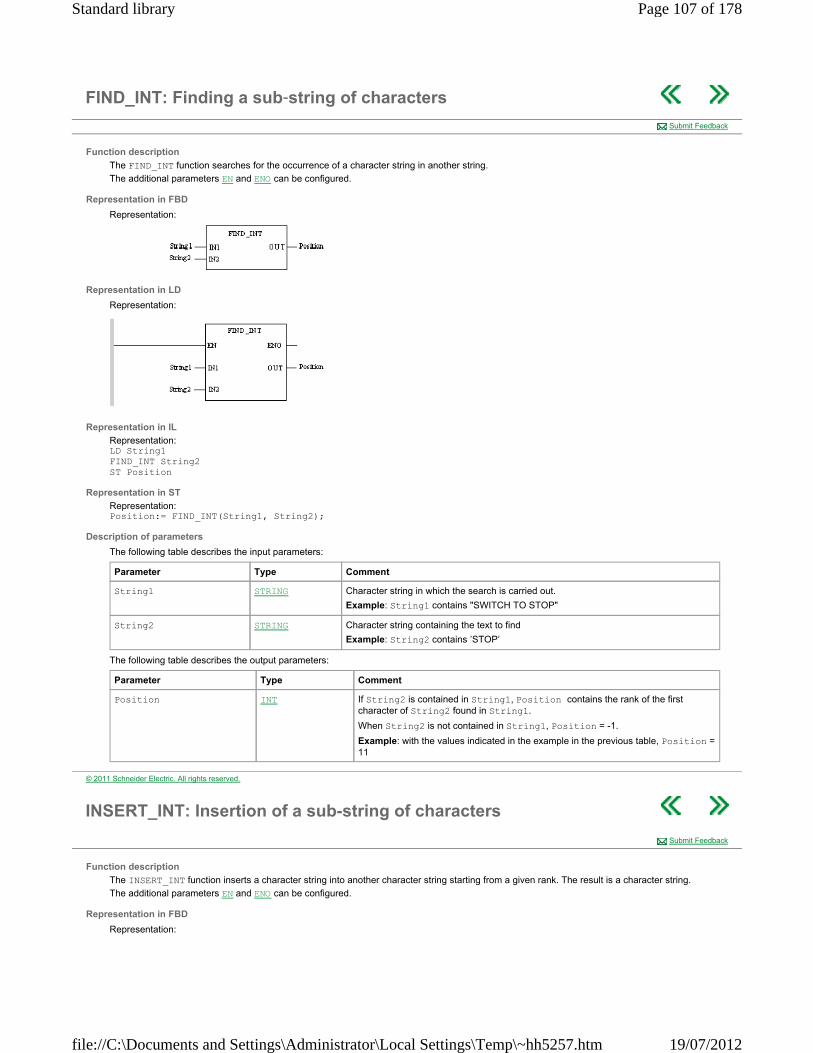
FIND_INT: Finding a sub‐string of characters
Function description
The FIND_INT function searches for the occurrence of a character string in another string.
The additional parameters EN and ENO can be configured.
Representation in FBD
Representation:
Representation in LD
Representation:
Representation in IL
Representation: LD String1 FIND_INT String2 ST Position
Representation in ST
Representation: Position:= FIND_INT(String1, String2);
Description of parameters
The following table describes the input parameters:
The following table describes the output parameters:
Submit Feedback
Parameter Type Comment
String1 STRING Character string in which the search is carried out.
Example: String1 contains "SWITCH TO STOP"
String2 STRING Character string containing the text to find
Example: String2 contains ’STOP’
Parameter Type Comment
Position INT If String2 is contained in String1, Position contains the rank of the first character of String2 found in String1.
When String2 is not contained in String1, Position = -1.
Example: with the values indicated in the example in the previous table, Position = 11
© 2011 Schneider Electric. All rights reserved.
INSERT_INT: Insertion of a sub-string of characters
Function description
The INSERT_INT function inserts a character string into another character string starting from a given rank. The result is a character string.
The additional parameters EN and ENO can be configured.
Representation in FBD
Representation:
Submit Feedback
Page 107 of 178Standard library
19/07/2012file://C:\Documents and Settings\Administrator\Local Settings\Temp\~hh5257.htm
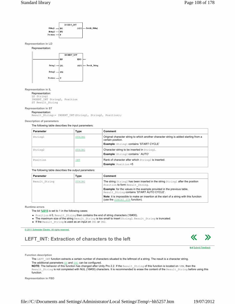
Representation in LD
Representation:
Representation in IL
Representation: LD String1 INSERT_INT String2, Position ST Result_String
Representation in ST
Representation: Result_String:= INSERT_INT(String1, String2, Position);
Description of parameters
The following table describes the input parameters:
The following table describes the output parameters:
Runtime errors
The bit %S15 is set to 1 in the following cases:
Position ≤ 0, Result_String then contains the end of string characters (16#00). The maximum size of the string Result_String is too small to insert String2. Result_String is truncated. If the Result_String is used as an input on IN1 or IN2.
Parameter Type Comment
String1 STRING Original character string to which another character string is added starting from a certain position.
Example: String1 contains ’START CYCLE’
String2 STRING Character string to be inserted in String1.
Example: String2 contains ’ AUTO’
Position INT Rank of character after which String2 is inserted.
Example: Position =5
Parameter Type Comment
Result_String STRING The string String2 has been inserted in the string String1 after the position Position to form Result_String.
Example: for the values in the example provided in the previous table, Result_String contains ’START AUTO CYCLE’.
Note: it is impossible to make an insertion at the start of a string with this function (use the CONCAT_STR function).
© 2011 Schneider Electric. All rights reserved.
LEFT_INT: Extraction of characters to the left
Function description
The LEFT_INT function extracts a certain number of characters situated to the leftmost of a string. The result is a character string.
The additional parameters EN and ENO can be configured. NOTE: The behavior of this function has changed after Unity Pro 2.2. If the Result_String of this function is located on %MW, then the Result_String is not completed with NUL (16#00) characters. It is recommended to erase the content of the Result_String before using this function.
Representation in FBD
Submit Feedback
Page 108 of 178Standard library
19/07/2012file://C:\Documents and Settings\Administrator\Local Settings\Temp\~hh5257.htm
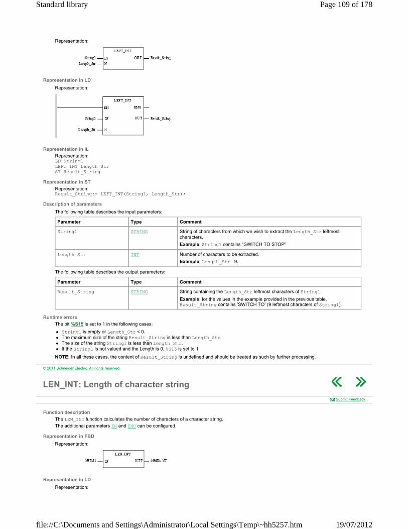
Representation:
Representation in LD
Representation:
Representation in IL
Representation: LD String1 LEFT_INT Length_Str ST Result_String
Representation in ST
Representation: Result_String:= LEFT_INT(String1, Length_Str);
Description of parameters
The following table describes the input parameters:
The following table describes the output parameters:
Runtime errors
The bit %S15 is set to 1 in the following cases:
String1 is empty or Length_Str < 0. The maximum size of the string Result_String is less than Length_Str The size of the string String1 is less than Length_Str. If the String1 is not valued and the Length is 0, %S15 is set to 1
NOTE: In all these cases, the content of Result_String is undefined and should be treated as such by further processing.
Parameter Type Comment
String1 STRING String of characters from which we wish to extract the Length_Str leftmost characters.
Example: String1 contains "SWITCH TO STOP"
Length_Str INT Number of characters to be extracted.
Example: Length_Str =9.
Parameter Type Comment
Result_String STRING String containing the Length_Str leftmost characters of String1.
Example: for the values in the example provided in the previous table, Result_String contains ’SWITCH TO’ (9 leftmost characters of String1).
© 2011 Schneider Electric. All rights reserved.
LEN_INT: Length of character string
Function description
The LEN_INT function calculates the number of characters of a character string.
The additional parameters EN and ENO can be configured.
Representation in FBD
Representation:
Representation in LD
Representation:
Submit Feedback
Page 109 of 178Standard library
19/07/2012file://C:\Documents and Settings\Administrator\Local Settings\Temp\~hh5257.htm
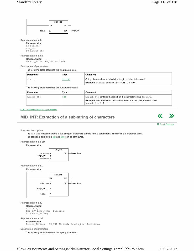
Representation in IL
Representation: LD String1 LEN_INT ST Length_Str
Representation in ST
Representation: Length_Str:= LEN_INT(String1);
Description of parameters
The following table describes the input parameters:
The following table describes the output parameters:
Parameter Type Comment
String1 STRING String of characters for which the length is to be determined.
Example: String1 contains "SWITCH TO STOP"
Parameter Type Comment
Length_Str INT Length_Str contains the length of the character string String1.
Example: with the values indicated in the example in the previous table, Length_Str = 14
© 2011 Schneider Electric. All rights reserved.
MID_INT: Extraction of a sub‐string of characters
Function description
The MID_INT function extracts a sub-string of characters starting from a certain rank. The result is a character string.
The additional parameters EN and ENO can be configured.
Representation in FBD
Representation:
Representation in LD
Representation:
Representation in IL
Representation: LD String1 MID_INT Length_Str, Position ST Result_String
Representation in ST
Representation: Result_String:= MID_INT(String1, Length_Str, Position);
Description of parameters
The following table describes the input parameters:
Submit Feedback
Page 110 of 178Standard library
19/07/2012file://C:\Documents and Settings\Administrator\Local Settings\Temp\~hh5257.htm
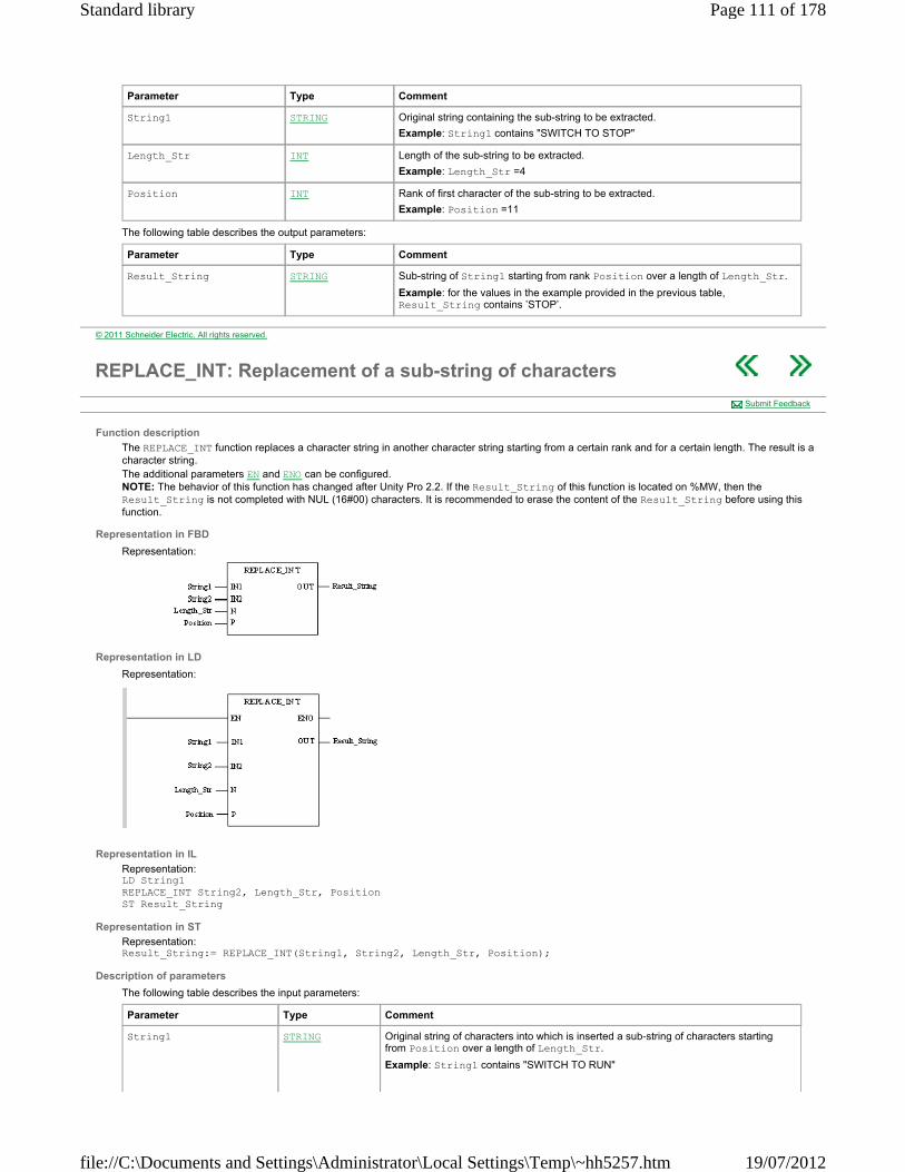
The following table describes the output parameters:
Parameter Type Comment
String1 STRING Original string containing the sub-string to be extracted.
Example: String1 contains "SWITCH TO STOP"
Length_Str INT Length of the sub-string to be extracted.
Example: Length_Str =4
Position INT Rank of first character of the sub-string to be extracted.
Example: Position =11
Parameter Type Comment
Result_String STRING Sub-string of String1 starting from rank Position over a length of Length_Str.
Example: for the values in the example provided in the previous table, Result_String contains ’STOP’.
© 2011 Schneider Electric. All rights reserved.
REPLACE_INT: Replacement of a sub-string of characters
Function description
The REPLACE_INT function replaces a character string in another character string starting from a certain rank and for a certain length. The result is a character string. The additional parameters EN and ENO can be configured. NOTE: The behavior of this function has changed after Unity Pro 2.2. If the Result_String of this function is located on %MW, then the Result_String is not completed with NUL (16#00) characters. It is recommended to erase the content of the Result_String before using this function.
Representation in FBD
Representation:
Representation in LD
Representation:
Representation in IL
Representation: LD String1 REPLACE_INT String2, Length_Str, Position ST Result_String
Representation in ST
Representation: Result_String:= REPLACE_INT(String1, String2, Length_Str, Position);
Description of parameters
The following table describes the input parameters:
Submit Feedback
Parameter Type Comment
String1 STRING Original string of characters into which is inserted a sub-string of characters starting from Position over a length of Length_Str.
Example: String1 contains "SWITCH TO RUN"
Page 111 of 178Standard library
19/07/2012file://C:\Documents and Settings\Administrator\Local Settings\Temp\~hh5257.htm
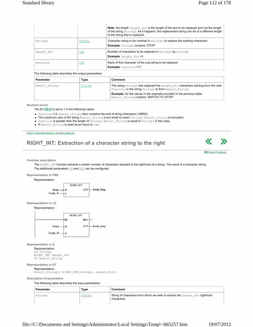
The following table describes the output parameters:
Runtime errors
The bit %S15 is set to 1 in the following cases:
Position ≤ 0, Result_String then contains the end of string characters (16#00). The maximum size of the string Result_String is too small to insert String2. Result_String is truncated. Position is greater than the length of String1. Result_String is equal to String1 in this case. If Result_String is used as an input on IN2.
Note: the length Length_Str is the length of the text to be replaced and not the length of the string String2. As it happens, the replacement string can be of a different length to the string that is replaced.
String2 STRING Character string to be inserted in String1 to replace the existing characters.
Example: String2 contains ’STOP’
Length_Str INT Number of characters to be replaced in String1 by String2
Example: Length_Str =3
Position INT Rank of first character of the sub-string to be replaced
Example: Position =11
Parameter Type Comment
Result_String STRING The string string2 has replaced the Length_Str characters starting from the rank Position in the string String1 to form Result_String.
Example: for the values in the example provided in the previous table, Result_String contains ’SWITCH TO STOP’.
© 2011 Schneider Electric. All rights reserved.
RIGHT_INT: Extraction of a character string to the right
Function description
The RIGHT_INT function extracts a certain number of characters situated to the rightmost of a string. The result is a character string.
The additional parameters EN and ENO can be configured.
Representation in FBD
Representation:
Representation in LD
Representation:
Representation in IL
Representation: LD String1 RIGHT_INT Length_Str ST Result_String
Representation in ST
Representation: Result_String:= RIGHT_INT(String1, Length_Str);
Description of parameters
The following table describes the input parameters:
Submit Feedback
Parameter Type Comment
String1 STRING String of characters from which we wish to extract the Length_Str rightmost characters.
Page 112 of 178Standard library
19/07/2012file://C:\Documents and Settings\Administrator\Local Settings\Temp\~hh5257.htm
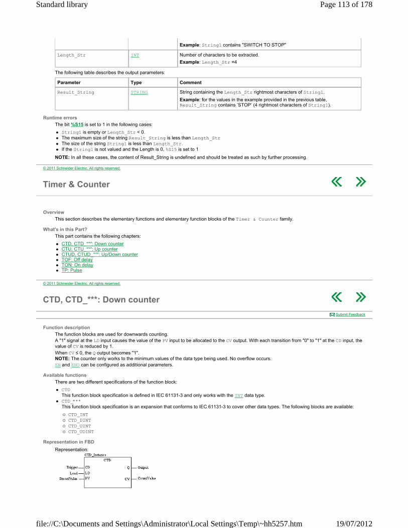
The following table describes the output parameters:
Runtime errors
The bit %S15 is set to 1 in the following cases:
String1 is empty or Length_Str < 0. The maximum size of the string Result_String is less than Length_Str The size of the string String1 is less than Length_Str. If the String1 is not valued and the Length is 0, %S15 is set to 1
NOTE: In all these cases, the content of Result_String is undefined and should be treated as such by further processing.
Example: String1 contains "SWITCH TO STOP"
Length_Str INT Number of characters to be extracted.
Example: Length_Str =4
Parameter Type Comment
Result_String STRING String containing the Length_Str rightmost characters of String1.
Example: for the values in the example provided in the previous table, Result_String contains ’STOP’ (4 rightmost characters of String1).
© 2011 Schneider Electric. All rights reserved.
Timer & Counter
Overview
This section describes the elementary functions and elementary function blocks of the Timer & Counter family.
What's in this Part?
This part contains the following chapters:
CTD, CTD_***: Down counter CTU, CTU_***: Up counter CTUD, CTUD_***: Up/Down counter TOF: Off delay TON: On delay TP: Pulse
© 2011 Schneider Electric. All rights reserved.
CTD, CTD_***: Down counter
Function description
The function blocks are used for downwards counting. A "1" signal at the LD input causes the value of the PV input to be allocated to the CV output. With each transition from "0" to "1" at the CD input, the value of CV is reduced by 1.
When CV ≤ 0, the Q output becomes "1". NOTE: The counter only works to the minimum values of the data type being used. No overflow occurs. EN and ENO can be configured as additional parameters.
Available functions
There are two different specifications of the function block:
CTD This function block specification is defined in IEC 61131-3 and only works with the INT data type.
CTD_*** This function block specification is an expansion that conforms to IEC 61131-3 to cover other data types. The following blocks are available:
CTD_INT CTD_DINT CTD_UINT CTD_UDINT
Representation in FBD
Representation:
Submit Feedback
Page 113 of 178Standard library
19/07/2012file://C:\Documents and Settings\Administrator\Local Settings\Temp\~hh5257.htm
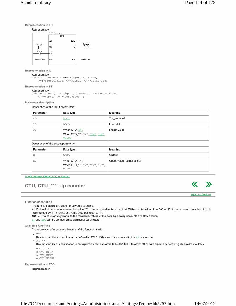
Representation in LD
Representation:
Representation in IL
Representation: CAL CTD_Instance (CD:=Trigger, LD:=Load, PV:=PresetValue, Q=>Output, CV=>CountValue)
Representation in ST
Representation: CTD_Instance (CD:=Trigger, LD:=Load, PV:=PresetValue, Q=>Output, CV=>CountValue) ;
Parameter description
Description of the input parameters:
Description of the output parameter:
Parameter Data type Meaning
CD BOOL Trigger input
LD BOOL Load data
PV When CTD: INT
When CTD_***: INT, DINT, UINT, UDINT
Preset value
Parameter Data type Meaning
Q BOOL Output
CV When CTD: INT
When CTD_***: INT, DINT, UINT, UDINT
Count value (actual value)
© 2011 Schneider Electric. All rights reserved.
CTU, CTU_***: Up counter
Function description
The function blocks are used for upwards counting. A "1" signal at the R input causes the value "0" to be assigned to the CV output. With each transition from "0" to "1" at the CU input, the value of CV is incremented by 1. When CV ≥ PV, the Q output is set to "1". NOTE: The counter only works to the maximum values of the data type being used. No overflow occurs. EN and ENO can be configured as additional parameters.
Available functions
There are two different specifications of the function block:
CTU This function block specification is defined in IEC 61131-3 and only works with the INT data type.
CTU_*** This function block specification is an expansion that conforms to IEC 61131-3 to cover other data types. The following blocks are available
CTU_INT CTU_DINT CTU_UINT CTU_UDINT
Representation in FBD
Representation:
Submit Feedback
Page 114 of 178Standard library
19/07/2012file://C:\Documents and Settings\Administrator\Local Settings\Temp\~hh5257.htm
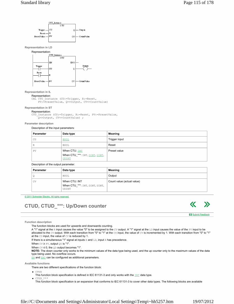
Representation in LD
Representation:
Representation in IL
Representation: CAL CTU_Instance (CU:=Trigger, R:=Reset, PV:=PresetValue, Q=>Output, CV=>CountValue)
Representation in ST
Representation: CTU_Instance (CU:=Trigger, R:=Reset, PV:=PresetValue, Q=>Output, CV=>CountValue) ;
Parameter description
Description of the input parameters:
Description of the output parameter:
Parameter Data type Meaning
CU BOOL Trigger input
R BOOL Reset
PV When CTU: INT
When CTU_***: INT, DINT, UINT, UDINT
Preset value
Parameter Data type Meaning
Q BOOL Output
CV When CTU: INT
When CTU_***: INT, DINT, UINT, UDINT
Count value (actual value)
© 2011 Schneider Electric. All rights reserved.
CTUD, CTUD_***: Up/Down counter
Function description
The function blocks are used for upwards and downwards counting. A "1" signal at the R input causes the value "0" to be assigned to the CV output. A "1" signal at the LD input causes the value of the PV input to be allocated to the CV output. With each transition from "0" to "1" at the CU input, the value of CV is incremented by 1. With each transition from "0" to "1" at the CD input, the value of CV is reduced by 1.
If there is a simultaneous "1" signal at inputs R and LD, input R has precedence.
When CV ≥ PV, output QU is "1".
When CV ≤ 0, the QD output becomes "1". NOTE: The down counter only works to the minimum values of the data type being used, and the up counter only to the maximum values of the data type being used. No overflow occurs. EN and ENO can be configured as additional parameters.
Available functions
There are two different specifications of the function block:
CTUD This function block specification is defined in IEC 61131-3 and only works with the INT data type.
CTUD_*** This function block specification is an expansion that conforms to IEC 61131-3 to cover other data types. The following blocks are available
Submit Feedback
Page 115 of 178Standard library
19/07/2012file://C:\Documents and Settings\Administrator\Local Settings\Temp\~hh5257.htm

CTUD_INT CTUD_DINT CTUD_UINT CTUD_UDINT
Representation in FBD
Representation:
Representation in LD
Representation:
Representation in IL
Representation: CAL CTUD_Instance (CU:=UpTrigger, CD:=DownTrigger, R:=Reset, LD:=Load, PV:=PresetValue, QU=>UpDisplay, QD=>DownDisplay, CV=>CountValue)
Representation in ST
Representation: CTUD_Instance (CU:=UpTrigger, CD:=DownTrigger, R:=Reset, LD:=Load, PV:=PresetValue, QU=>UpDisplay, QD=>DownDisplay, CV=>CountValue) ;
Parameter description
Description of the input parameters:
Description of the output parameter:
Parameter Data type Meaning
CU BOOL Up counter trigger input
CD BOOL Down counter trigger input
R BOOL Reset
LD BOOL Load data
PV When CTUD: INT,
When CTUD_***: INT, DINT, UINT, UDINT
Preset value
Parameter Data type Meaning
QU BOOL Up display
QD BOOL Down display
CV When CTUD: INT
When CTUD_***: INT, DINT, UINT, UDINT
Count value (actual value)
© 2011 Schneider Electric. All rights reserved.
TOF: Off delay
Submit Feedback
Page 116 of 178Standard library
19/07/2012file://C:\Documents and Settings\Administrator\Local Settings\Temp\~hh5257.htm

Function description
The function block is used as the Off delay. When the function block is called for the first time, the initial state of ET is "0".
EN and ENO can be configured as additional parameters.
Representation in FBD
Representation:
Representation in LD
Representation:
Representation in IL
Representation: CAL TOF_Instance (IN:=StartDelay, PT:=PresetDelayTime, Q=>Output, ET=>InternalTime)
Representation in ST
Representation: TOF_Instance (IN:=StartDelay, PT:=PresetDelayTime, Q=>Output, ET=>InternalTime) ;
Parameter description
Description of the input parameters:
Description of the output parameter:
Timing diagram
Representation of the OFF delay TOF:
If IN becomes "1", Q becomes "1". If IN becomes "0", the internal time (ET) is started. If the internal time reaches the value of PT, Q becomes "0". If IN becomes "1", Q becomes "1", and the internal time is stopped/reset. If IN becomes "1" before the internal time has reached the value of PT, the internal time is stopped/reset without Q being set back to "0".
Parameter Data type Meaning
IN BOOL Start delay
PT TIME Preset delay time
Parameter Data type Meaning
Q BOOL Output
ET TIME Internal time
(1) (2) (3) (4) (5)
© 2011 Schneider Electric. All rights reserved.
TON: On delay
Function description
The function block is used as the On delay.
Submit Feedback
Page 117 of 178Standard library
19/07/2012file://C:\Documents and Settings\Administrator\Local Settings\Temp\~hh5257.htm

When the function block is called for the first time, the initial state of ET is "0".
EN and ENO can be configured as additional parameters.
Representation in FBD
Representation:
Representation in LD
Representation:
Representation in IL
Representation: CAL TON_Instance (IN:=StartDelay, PT:=PresetDelayTime, Q=>Output, ET=>InternalTime)
Representation in ST
Representation: TON_Instance (IN:=StartDelay, PT:=PresetDelayTime, Q=>Output, ET=>InternalTime) ;
Parameter description
Description of the input parameters:
Description of the output parameter:
Timing diagram
Representation of the ON delay TON:
If IN becomes "1", the internal time (ET) starts. If the internal time reaches the value of PT, Q becomes "1". If IN becomes "0", Q becomes "0" and the internal time is stopped/reset. If IN becomes "0" before the internal time has reached the value of PT, the internal time stops/resets without Q going to "1".
Parameter Data type Meaning
IN BOOL Start delay
PT TIME Preset delay time
Parameter Data type Meaning
Q BOOL Output
ET TIME Internal time
(1) (2) (3) (4)
© 2011 Schneider Electric. All rights reserved.
TP: Pulse
Function description
The function block is used for the generation of a pulse with defined duration. When the function block is called for the first time, the initial state of ET is "0".
EN and ENO can be configured as additional parameters.
Representation in FBD
Submit Feedback
Page 118 of 178Standard library
19/07/2012file://C:\Documents and Settings\Administrator\Local Settings\Temp\~hh5257.htm
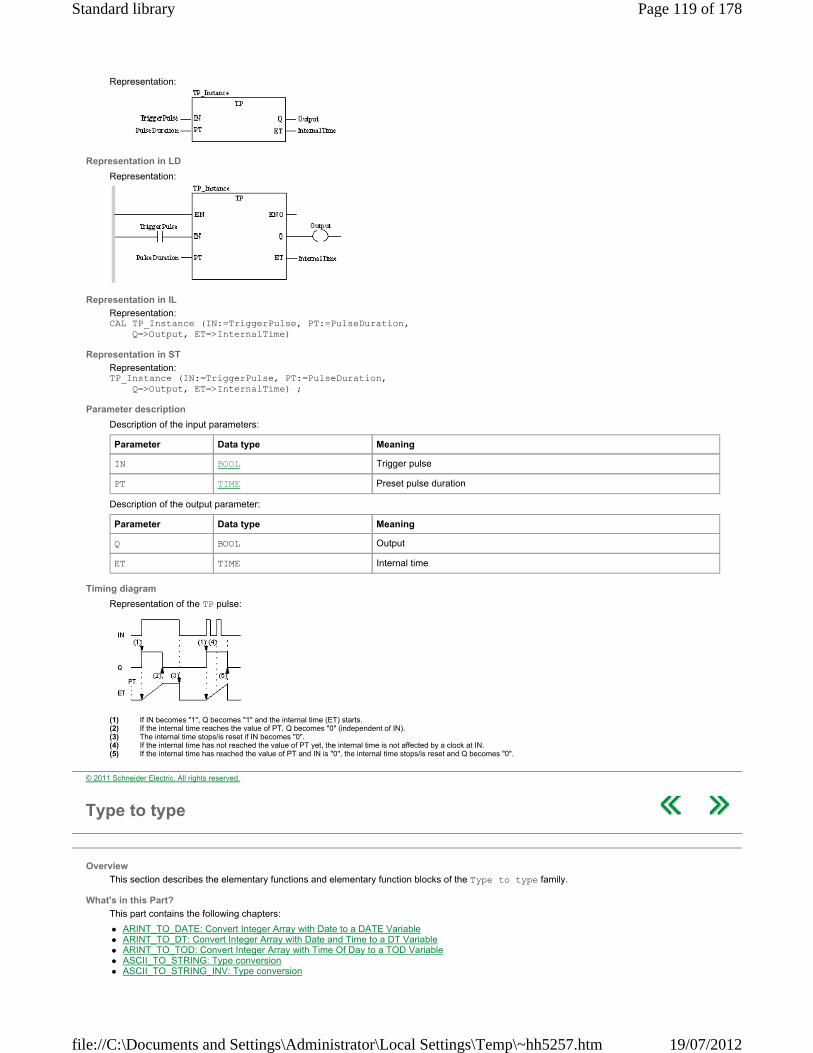
Representation:
Representation in LD
Representation:
Representation in IL
Representation: CAL TP_Instance (IN:=TriggerPulse, PT:=PulseDuration, Q=>Output, ET=>InternalTime)
Representation in ST
Representation: TP_Instance (IN:=TriggerPulse, PT:=PulseDuration, Q=>Output, ET=>InternalTime) ;
Parameter description
Description of the input parameters:
Description of the output parameter:
Timing diagram
Representation of the TP pulse:
If IN becomes "1", Q becomes "1" and the internal time (ET) starts. If the internal time reaches the value of PT, Q becomes "0" (independent of IN). The internal time stops/is reset if IN becomes "0". If the internal time has not reached the value of PT yet, the internal time is not affected by a clock at IN. If the internal time has reached the value of PT and IN is "0", the internal time stops/is reset and Q becomes "0".
Parameter Data type Meaning
IN BOOL Trigger pulse
PT TIME Preset pulse duration
Parameter Data type Meaning
Q BOOL Output
ET TIME Internal time
(1) (2) (3) (4) (5)
© 2011 Schneider Electric. All rights reserved.
Type to type
Overview
This section describes the elementary functions and elementary function blocks of the Type to type family.
What's in this Part?
This part contains the following chapters:
ARINT_TO_DATE: Convert Integer Array with Date to a DATE Variable ARINT_TO_DT: Convert Integer Array with Date and Time to a DT Variable ARINT_TO_TOD: Convert Integer Array with Time Of Day to a TOD Variable ASCII_TO_STRING: Type conversion ASCII_TO_STRING_INV: Type conversion
Page 119 of 178Standard library
19/07/2012file://C:\Documents and Settings\Administrator\Local Settings\Temp\~hh5257.htm
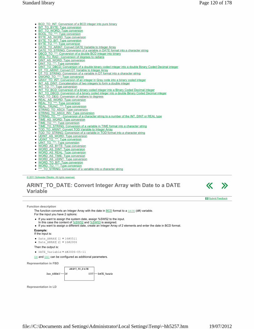
BCD_TO_INT: Conversion of a BCD integer into pure binary BIT_TO_BYTE: Type conversion BIT_TO_WORD: Type conversion BOOL_TO_***: Type conversion BYTE_AS_WORD: Type conversion BYTE_TO_BIT: Type conversion BYTE_TO_***: Type conversion DATE_TO_ARINT: Convert DATE Variable to Integer Array DATE_TO_STRING: Conversion of a variable in DATE format into a character string DBCD_TO_***: Conversion of a double BCD integer into binary DEG_TO_RAD : Conversion of degrees to radians DINT_AS_WORD: Type conversion DINT_TO_***: Type conversion DINT_TO_DBCD: Conversion of a double binary coded integer into a double Binary Coded Decimal integer DT_TO_ARINT: Convert DT Variable to Integer Array DT_TO_STRING: Conversion of a variable in DT format into a character string DWORD_TO_***: Type conversion GRAY_TO_INT: Conversion of an integer in Gray code into a binary coded integer INT_AS_DINT: Concatenation of two integers to form a double integer INT_TO_***: Type conversion INT_TO_BCD: Conversion of a binary coded integer into a Binary Coded Decimal integer INT_TO_DBCD: Conversion of a binary coded integer into a double Binary Coded Decimal integer RAD_TO_DEG: Conversion of radians to degrees REAL_AS_WORD: Type conversion REAL_TO_***: Type conversion REAL_TRUNC_***: Type conversion STRING_TO_ASCII: Type conversion STRING_TO_ASCII_INV: Type conversion STRING_TO_*** : Conversion of a character string to a number of the INT, DINT or REAL type TIME_AS_WORD: Type conversion TIME_TO_***: Type conversion TIME_TO_STRING: Conversion of a variable in TIME format into a character string TOD_TO_ARINT: Convert TOD Variable to Integer Array TOD_TO_STRING: Conversion of a variable in TOD format into a character string UDINT_AS_WORD: Type conversion UDINT_TO_***: Type conversion UINT_TO_***: Type conversion WORD_AS_BYTE: Type conversion WORD_AS_DINT: Type conversion WORD_AS_REAL: Type conversion WORD_AS_TIME: Type conversion WORD_AS_UDINT: Type conversion WORD_TO_BIT: Type conversion WORD_TO_***: Type conversion ***_TO_STRING: Conversion of a variable into a character string
© 2011 Schneider Electric. All rights reserved.
ARINT_TO_DATE: Convert Integer Array with Date to a DATE Variable
Function description
The function converts an Integer Array with the date in BCD format to a DATE (d#) variable. For the input you have 2 options:
If you want to assign the system date, assign %SW52 to the input. In this case the content of %SW52 and %SW53 is assigned.
If you want to assign a different date, create an Integer Array of 2 elements and enter the date in BCD format.
Example: If the input is:
Date_ARRAY[1] = 16#0511 Date_ARRAY[2] = 16#2006
Then the output is:
DATE_Variable = d#2006-05-11
EN and ENO can be configured as additional parameters.
Representation in FBD
Representation in LD
Submit Feedback
Page 120 of 178Standard library
19/07/2012file://C:\Documents and Settings\Administrator\Local Settings\Temp\~hh5257.htm

Representation in IL LD Date_ARRAY ARINT_TO_DATE ST DATE_Variable
Representation in ST DATE_Variable := ARINT_TO_DATE (Date_ARRAY) ;
Parameter description
Description of input parameters:
Description of output parameters:
Runtime errors
If input Date_ARRAY is invalid, ENO = 0 and OUT remains unchanged.
Parameter Data type Meaning
Date_ARRAY ARRAY [n..m] OF INT Integer ARRAY of 2 elements with the date in BCD format:
month, day (16#mmdd),
corresponds to %SW52 year (16#yyyy),
corresponds to %SW53
Parameter Data type Meaning
DATE_Variable DATE Date assigned to the input as DATE (d#) variable (if input is valid).
© 2011 Schneider Electric. All rights reserved.
ARINT_TO_DT: Convert Integer Array with Date and Time to a DT Variable
Function description
The function converts an Integer Array with date and time in BCD format to a DATE_AND_TIME (dt#) variable. For the input you have 2 options:
If you want to assign the system time, assign %SW50 to the input. In this case the content of %SW50 to %SW53 is assigned.
If you want to assign a different time, create an Integer Array of 4 elements and enter time and date in BCD format.
Example: If the input is:
DateAndTime_ARRAY[1] = 16#1600 DateAndTime_ARRAY[2] = 16#1046 DateAndTime_ARRAY[3] = 16#0511 DateAndTime_ARRAY[4] = 16#2006
Then the output is:
DT_Variable = dt#2006-05-11-10:46:16
EN and ENO can be configured as additional parameters.
Representation in FBD
Representation in LD
Submit Feedback
Page 121 of 178Standard library
19/07/2012file://C:\Documents and Settings\Administrator\Local Settings\Temp\~hh5257.htm

Representation in IL LD DateAndTime_ARRAY ARINT_TO_DT ST DT_Variable
Representation in ST DT_Variable := ARINT_TO_DT (DateAndTime_ARRAY) ;
Parameter description
Description of input parameters:
Description of output parameters:
Runtime errors
If input DateAndTime_ARRAY is invalid, ENO = 0 and OUT remains unchanged.
Parameter Data type Meaning
DateAndTime_ARRAY ARRAY [n..m] OF INT Integer ARRAY of 4 elements with the date and time in BCD format:
seconds,-- (16#ss,--),
corresponds to %SW50 hour, minute (16#hhmm),
corresponds to %SW51 month, day (16#mmdd),
corresponds to %SW52 year (16#yyyy),
corresponds to %SW53
Parameter Data type Meaning
DT_Variable DT Date and time assigned to the input as DATE_AND_TIME (dt#) variable (if input is valid).
© 2011 Schneider Electric. All rights reserved.
ARINT_TO_TOD: Convert Integer Array with Time Of Day to a TOD Variable
Function description
The function converts an Integer Array with the time of day in BCD format to a TIME_OF_DAY (tod#) variable. For the input you have 2 options:
If you want to assign the system time, assign %SW50 to the input. In this case the content of %SW50 and %SW51 is assigned.
If you want to assign a different time, create an Integer Array of 2 elements and enter the time of day in BCD format.
Example: If the input is:
Time_ARRAY[1] = 16#1600 Time_ARRAY[2] = 16#1046
Then the output is:
TOD_Variable = tod#10:46:16
EN and ENO can be configured as additional parameters.
Representation in FBD
Representation in LD
Submit Feedback
Page 122 of 178Standard library
19/07/2012file://C:\Documents and Settings\Administrator\Local Settings\Temp\~hh5257.htm
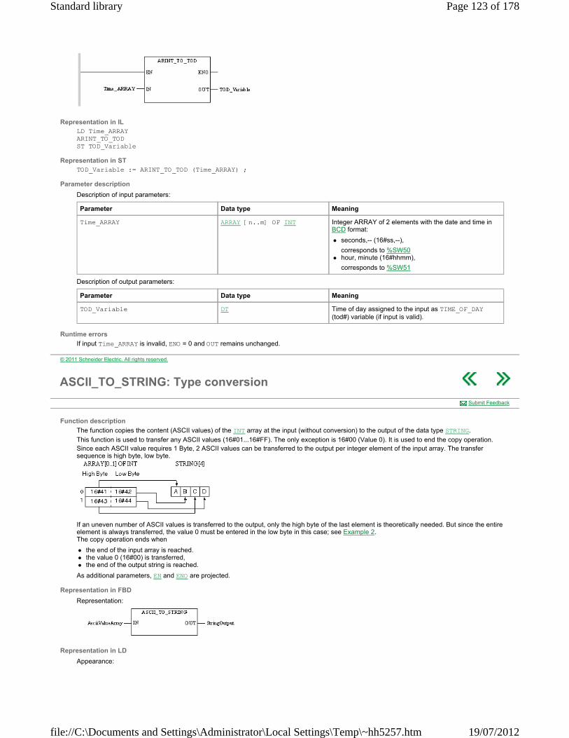
Representation in IL LD Time_ARRAY ARINT_TO_TOD ST TOD_Variable
Representation in ST TOD_Variable := ARINT_TO_TOD (Time_ARRAY) ;
Parameter description
Description of input parameters:
Description of output parameters:
Runtime errors
If input Time_ARRAY is invalid, ENO = 0 and OUT remains unchanged.
Parameter Data type Meaning
Time_ARRAY ARRAY [n..m] OF INT Integer ARRAY of 2 elements with the date and time in BCD format:
seconds,-- (16#ss,--),
corresponds to %SW50 hour, minute (16#hhmm),
corresponds to %SW51
Parameter Data type Meaning
TOD_Variable DT Time of day assigned to the input as TIME_OF_DAY (tod#) variable (if input is valid).
© 2011 Schneider Electric. All rights reserved.
ASCII_TO_STRING: Type conversion
Function description
The function copies the content (ASCII values) of the INT array at the input (without conversion) to the output of the data type STRING.
This function is used to transfer any ASCII values (16#01...16#FF). The only exception is 16#00 (Value 0). It is used to end the copy operation. Since each ASCII value requires 1 Byte, 2 ASCII values can be transferred to the output per integer element of the input array. The transfer sequence is high byte, low byte.
If an uneven number of ASCII values is transferred to the output, only the high byte of the last element is theoretically needed. But since the entire element is always transferred, the value 0 must be entered in the low byte in this case; see Example 2. The copy operation ends when
the end of the input array is reached. the value 0 (16#00) is transferred, the end of the output string is reached.
As additional parameters, EN and ENO are projected.
Representation in FBD
Representation:
Representation in LD
Appearance:
Submit Feedback
Page 123 of 178Standard library
19/07/2012file://C:\Documents and Settings\Administrator\Local Settings\Temp\~hh5257.htm

Representation in IL
Appearance: LD AsciiValueArray ASCII_TO_STRING ST StringOutput
Representation in ST
Appearance: StringOutput := ASCII_TO_STRING (AsciiValueArray) ;
Parameter description
Description of input parameters:
Description of output parameters:
Runtime error
If the size of the string variables at the output is insufficient to represent all ASCII values of the input array ENO is set to 0 and system bit %S15 is set to 1.
Example 1
In the example, 4 ASCII values are to be transferred to a string of 4 characters. This requires an integer array with 2 elements.
Example 2
In the example, 3 ASCII values are to be transferred to a string of 4 characters. This requires an integer array with 2 elements; the low byte of the second element is not required, and it therefore must contain the value 0.
Example 3
In the example, 4 ASCII values are to be transferred to a string of 8 characters. This requires an integer array with 2 elements. The unneeded 4 characters at the output remain empty in this case.
Example 4
In the example the first 4 ASCII values of an integer array with 8 elements are to be transferred to a string of 4 characters. This requires that the high byte of the third element of the integer array contains the value 0 to mark the end of the characters to be transferred. All other ASCII values are no longer considered.
Parameter Data type Description
AsciiValueArray ARRAY[n..m] OF INT Integer array with ASCII values
Parameter Data type Description
StringOutput STRING String of ASCII characters
Page 124 of 178Standard library
19/07/2012file://C:\Documents and Settings\Administrator\Local Settings\Temp\~hh5257.htm
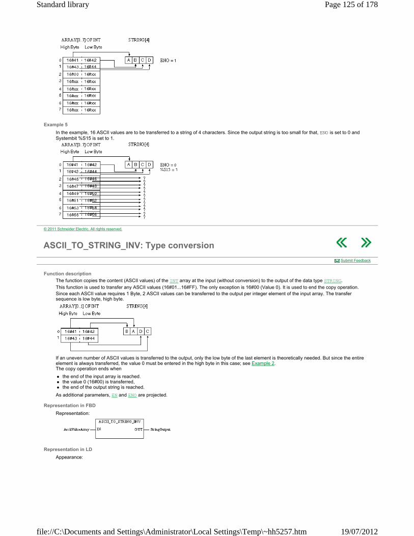
Example 5
In the example, 16 ASCII values are to be transferred to a string of 4 characters. Since the output string is too small for that, ENO is set to 0 and Systembit %S15 is set to 1.
© 2011 Schneider Electric. All rights reserved.
ASCII_TO_STRING_INV: Type conversion
Function description
The function copies the content (ASCII values) of the INT array at the input (without conversion) to the output of the data type STRING.
This function is used to transfer any ASCII values (16#01...16#FF). The only exception is 16#00 (Value 0). It is used to end the copy operation. Since each ASCII value requires 1 Byte, 2 ASCII values can be transferred to the output per integer element of the input array. The transfer sequence is low byte, high byte.
If an uneven number of ASCII values is transferred to the output, only the low byte of the last element is theoretically needed. But since the entire element is always transferred, the value 0 must be entered in the high byte in this case; see Example 2. The copy operation ends when
the end of the input array is reached. the value 0 (16#00) is transferred, the end of the output string is reached.
As additional parameters, EN and ENO are projected.
Representation in FBD
Representation:
Representation in LD
Appearance:
Submit Feedback
Page 125 of 178Standard library
19/07/2012file://C:\Documents and Settings\Administrator\Local Settings\Temp\~hh5257.htm

Representation in IL
Appearance: LD AsciiValueArray ASCII_TO_STRING_INV ST StringOutput
Representation in ST
Appearance: StringOutput := ASCII_TO_STRING_INV (AsciiValueArray) ;
Parameter description
Description of input parameters:
Description of output parameters:
Runtime error
If the size of the string variables at the output is insufficient to represent all ASCII values of the input array ENO is set to 0 and system bit %S15 is set to 1.
Example 1
In the example, 4 ASCII values are to be transferred to a string of 4 characters. This requires an integer array with 2 elements.
Example 2
In the example, 3 ASCII values are to be transferred to a string of 4 characters. This requires an integer array with 2 elements; the low byte of the second element is not required, and it therefore must contain the value 0.
Example 3
In the example, 4 ASCII values are to be transferred to a string of 8 characters. This requires an integer array with 2 elements. The unneeded 4 characters at the output remain empty in this case.
Example 4
In the example the first 4 ASCII values of an integer array with 8 elements are to be transferred to a string of 4 characters. This requires that the high byte of the third element of the integer array contains the value 0 to mark the end of the characters to be transferred. All other ASCII values are no longer considered.
Parameter Data type Description
AsciiValueArray ARRAY[n..m] OF INT Integer array with ASCII values
Parameter Data type Description
StringOutput STRING String of ASCII characters
Page 126 of 178Standard library
19/07/2012file://C:\Documents and Settings\Administrator\Local Settings\Temp\~hh5257.htm

Example 5
In the example, 16 ASCII values are to be transferred to a string of 4 characters. Since the output string is too small for that, ENO is set to 0 and Systembit %S15 is set to 1.
© 2011 Schneider Electric. All rights reserved.
BCD_TO_INT: Conversion of a BCD integer into pure binary
Function description
The BCD_TO_INT function converts an integer in Binary Coded Decimal (BCD) format into a binary coded integer.
The additional parameters EN and ENO can be configured.
Representation in FBD
Representation:
Representation in LD
Representation:
Representation in IL
Representation: LD BCD_Int BCD_TO_INT ST Result_Int
Representation in ST
Representation: Result_Int:= BCD_TO_INT(BCD_Int);
Description of parameters
The following table describes the input parameters:
Submit Feedback
Parameter Type Comment
Page 127 of 178Standard library
19/07/2012file://C:\Documents and Settings\Administrator\Local Settings\Temp\~hh5257.htm

The following table describes the output parameters:
Runtime errors
The bit %S18 is set to 1 when the value to be converted is not a value coded in BCD. The result of the function then returns the value of the input parameter.
BCD_Int INT Integer in BCD format.
Example: BCD_Int = 16#99
Parameter Type Comment
Result_Int INT Result_Int is a binary coded integer.
Example: with the value provided in the example in the previous table, Result_Int = 99
© 2011 Schneider Electric. All rights reserved.
BIT_TO_BYTE: Type conversion
Function description
The function converts 8 input values of the data type BOOL to an output of the BYTE data type.
The input values are assigned to the individual bits of the byte at the output according to the input names.
EN and ENO can be configured as additional parameters.
Formula
Block formula:
Representation in FBD
Representation:
Representation in LD
Representation:
Representation in IL
Submit Feedback
Page 128 of 178Standard library
19/07/2012file://C:\Documents and Settings\Administrator\Local Settings\Temp\~hh5257.htm

Representation: LD InputBit0 BIT_TO_BYTE InputBit1, InputBit2, InputBit3, InputBit4, InputBit5, InputBit6, InputBit7 ST OutputByte
Representation in ST
Representation: OutputByte := BIT_TO_BYTE (InputBit0, InputBit1, InputBit2, InputBit3, InputBit4, InputBit5, InputBit6, InputBit7) ;
Parameter description
Description of the input parameters:
Description of the output parameter:
Parameter Data type Meaning
InputBit0 BOOL Input bit 0
InputBit1 BOOL Input bit 1
: : :
InputBit7 BOOL Input bit 7
Parameter Data type Meaning
OutputByte BYTE Output value
© 2011 Schneider Electric. All rights reserved.
BIT_TO_WORD: Type conversion
Function description
The function converts 16 input values of the BOOL data type to an output value of the WORD data type.
The input values are assigned to the individual bits of the word at the output according to the input names.
EN and ENO can be configured as additional parameters.
Formula
Block formula:
Representation in FBD
Representation:
Representation in LD
Representation:
Representation in IL
Submit Feedback
Page 129 of 178Standard library
19/07/2012file://C:\Documents and Settings\Administrator\Local Settings\Temp\~hh5257.htm

Representation: LD InputBit0 BIT_TO_WORD InputBit1, InputBit2, InputBit3, InputBit4, InputBit5, InputBit6, InputBit7,InputBit8, InputBit9, InputBit10, InputBit11, InputBit12, InputBit13, InputBit14, InputBit15 ST WORD_Output
Representation in ST
Representation: WORD_Output := BIT_TO_WORD (InputBit0, InputBit1, InputBit2, InputBit3, InputBit4, InputBit5, InputBit6, InputBit7, InputBit8, InputBit9, InputBit10, InputBit11, InputBit12, InputBit13, InputBit14, InputBit15) ;
Parameter description
Description of the input parameters:
Description of the output parameter:
Parameter Data type Meaning
InputBit0 BOOL Input bit 0
: : :
InputBit15 BOOL Input bit 15
Parameter Data type Meaning
WORD_Output WORD Output value
© 2011 Schneider Electric. All rights reserved.
BOOL_TO_***: Type conversion
Function description
The function converts an input value of the BOOL data type to a BYTE, WORD, DWORD, INT, DINT, UINT, UDINT, REAL or TIME data type.
The input value is written in the lowest bit of the output. All other output bits are set to zero. EN and ENO can be configured as additional parameters.
(The output ENO is not used for BOOL_TO_REAL; it always has the value "1".)
Available functions
List of available functions:
BOOL_TO_BYTE BOOL_TO_WORD BOOL_TO_DWORD BOOL_TO_INT BOOL_TO_DINT BOOL_TO_UINT BOOL_TO_UDINT BOOL_TO_REAL BOOL_TO_TIME
Representation in FBD
Representation of an Integer application:
Representation in LD
Representation of an Integer application:
Representation in IL
Representation of an Integer application: LD BOOL_variable
Submit Feedback
Page 130 of 178Standard library
19/07/2012file://C:\Documents and Settings\Administrator\Local Settings\Temp\~hh5257.htm

BOOL_TO_INT ST ConvertedVariable
Representation in ST
Representation of an Integer application: ConvertedVariable := BOOL_TO_INT (BOOL_variable) ;
Parameter description
Description of the input parameters:
Description of the output parameter:
Parameter Data type Meaning
BOOL_variable BOOL Input value
Parameter Data type Meaning
ConvertedVariable BYTE, WORD, DWORD, INT, DINT, UINT, UDINT, REAL, TIME
Output value
© 2011 Schneider Electric. All rights reserved.
BYTE_AS_WORD: Type conversion
Function description
The function converts 2 input values of the BYTE data type to an output value of the WORD data type.
The input values are assigned to the word at the output according to the input names. EN and ENO can be configured as additional parameters.
Formula
Block formula:
Representation in FBD
Representation:
Representation in LD
Representation:
Representation in IL
Representation: LD BYTE_variable1 BYTE_AS_WORD BYTE_variable2 ST WORD_Output
Representation in ST
Representation: WORD_Output := BYTE_AS_WORD (BYTE_variable1, BYTE_variable2) ;
Parameter description
Description of the input parameters:
Description of the output parameter:
Submit Feedback
Parameter Data type Meaning
BYTE_variable1 BYTE least significant byte
BYTE_variable2 BYTE most significant byte
Parameter Data type Meaning
Page 131 of 178Standard library
19/07/2012file://C:\Documents and Settings\Administrator\Local Settings\Temp\~hh5257.htm
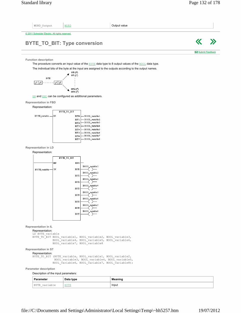
WORD_Output WORD Output value
© 2011 Schneider Electric. All rights reserved.
BYTE_TO_BIT: Type conversion
Function description
The procedure converts an input value of the BYTE data type to 8 output values of the BOOL data type.
The individual bits of the byte at the input are assigned to the outputs according to the output names.
EN and ENO can be configured as additional parameters.
Representation in FBD
Representation:
Representation in LD
Representation:
Representation in IL
Representation: LD BYTE_variable BYTE_TO_BIT BOOL_variable1, BOOL_variable2, BOOL_variable3, BOOL_variable4, BOOL_variable5, BOOL_variable6, BOOL_variable7, BOOL_variable8
Representation in ST
Representation: BYTE_TO_BIT (BYTE_variable, BOOL_variable1, BOOL_variable2, BOOL_variable3, BOOL_variable4, BOOL_variable5, BOOL_variable6, BOOL_variable7, BOOL_variable8);
Parameter description
Description of the input parameters:
Submit Feedback
Parameter Data type Meaning
BYTE_variable BYTE Input
Page 132 of 178Standard library
19/07/2012file://C:\Documents and Settings\Administrator\Local Settings\Temp\~hh5257.htm

Description of the output parameter:
Parameter Data type Meaning
BOOL_variable1 BOOL Output bit 0
BOOL_variable2 BOOL Output bit 1
: : :
BOOL_variable8 BOOL Output bit 7
© 2011 Schneider Electric. All rights reserved.
BYTE_TO_***: Type conversion
Function description
The function converts an input value of the BYTE data type to a BOOL, WORD, DWORD, INT, DINT, UINT, UDINT, REAL or TIME data type.
When converting the data type BYTE to the data type WORD, DWORD, INT, DINT, UINT, UDINT, REAL or TIME, the bit pattern of the input is transferred to the least significant bits of the output. The most significant bits of the output are set to zero. When converting the data type BYTE into the data type BOOL, the least significant bit of the input value is transferred to the output.
EN and ENO can be configured as additional parameters.
(The output ENO is not used for BYTE_TO_REAL; it always has the value "1".)
Available functions
List of available functions:
BYTE_TO_BOOL BYTE_TO_WORD BYTE_TO_DWORD BYTE_TO_INT BYTE_TO_DINT BYTE_TO_UINT BYTE_TO_UDINT BYTE_TO_REAL BYTE_TO_TIME
Representation in FBD
Representation of an Integer application:
Representation in LD
Representation of an Integer application:
Representation in IL
Representation of an Integer application: LD BYTE_variable BYTE_TO_INT ST ConvertedVariable
Representation in ST
Representation of an Integer application: ConvertedVariable := BYTE_TO_INT (BYTE_variable) ;
Parameter description
Description of input parameters:
Description of output parameters:
Submit Feedback
Parameter Data type Meaning
BYTE_variable BYTE Input value
Parameter Data type Meaning
ConvertedVariable BOOL, WORD, DWORD, INT, DINT, Output value
Page 133 of 178Standard library
19/07/2012file://C:\Documents and Settings\Administrator\Local Settings\Temp\~hh5257.htm
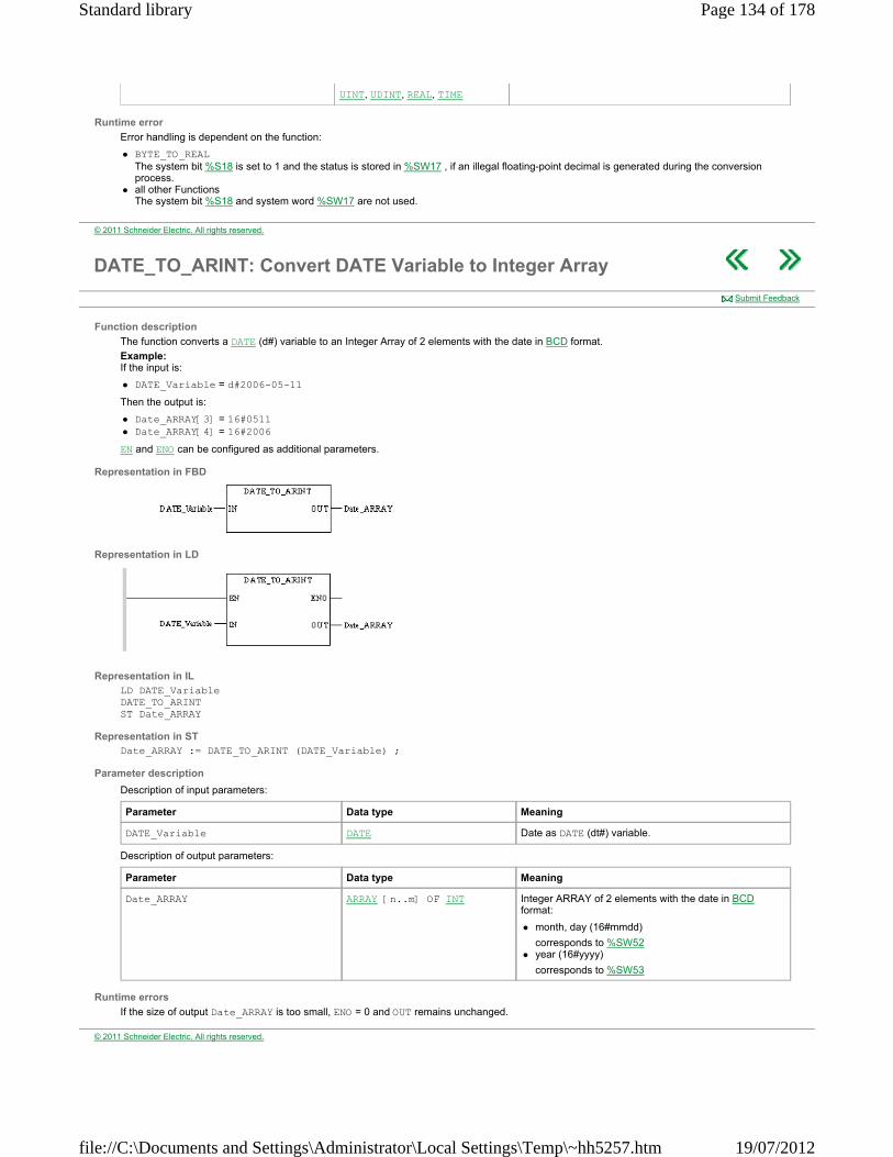
Runtime error
Error handling is dependent on the function:
BYTE_TO_REAL The system bit %S18 is set to 1 and the status is stored in %SW17 , if an illegal floating-point decimal is generated during the conversion process.
all other Functions The system bit %S18 and system word %SW17 are not used.
UINT, UDINT, REAL, TIME
© 2011 Schneider Electric. All rights reserved.
DATE_TO_ARINT: Convert DATE Variable to Integer Array
Function description
The function converts a DATE (d#) variable to an Integer Array of 2 elements with the date in BCD format.
Example: If the input is:
DATE_Variable = d#2006-05-11
Then the output is:
Date_ARRAY[3] = 16#0511 Date_ARRAY[4] = 16#2006
EN and ENO can be configured as additional parameters.
Representation in FBD
Representation in LD
Representation in IL LD DATE_Variable DATE_TO_ARINT ST Date_ARRAY
Representation in ST Date_ARRAY := DATE_TO_ARINT (DATE_Variable) ;
Parameter description
Description of input parameters:
Description of output parameters:
Runtime errors
If the size of output Date_ARRAY is too small, ENO = 0 and OUT remains unchanged.
Submit Feedback
Parameter Data type Meaning
DATE_Variable DATE Date as DATE (dt#) variable.
Parameter Data type Meaning
Date_ARRAY ARRAY [n..m] OF INT Integer ARRAY of 2 elements with the date in BCD format:
month, day (16#mmdd)
corresponds to %SW52 year (16#yyyy)
corresponds to %SW53
© 2011 Schneider Electric. All rights reserved.
Page 134 of 178Standard library
19/07/2012file://C:\Documents and Settings\Administrator\Local Settings\Temp\~hh5257.htm
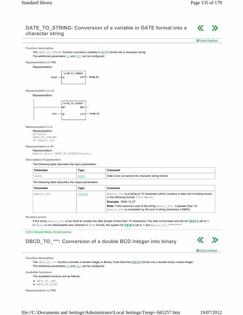
DATE_TO_STRING: Conversion of a variable in DATE format into a character string
Function description
The DATE_TO_STRING function converts a variable in DATE format into a character string.
The additional parameters EN and ENO can be configured.
Representation in FBD
Representation:
Representation in LD
Representation:
Representation in IL
Representation: LD Date1 DATE_TO_STRING ST Result_Str
Representation in ST
Representation: Result_Str:= DATE_TO_STRING(Date1);
Description of parameters
The following table describes the input parameters:
The following table describes the output parameters:
Runtime errors
If the string Result_Str is too short to contain the date (length of less than 10 characters), the date is truncated and the bit %S15 is set to 1.
If Date1 in not interpretable and coherent in DATE format, the system bit %S18 is set to 1 and Result_Str =’****-**-**’
Submit Feedback
Parameter Type Comment
Date1 DATE Date to be converted into character string format.
Parameter Type Comment
Result_Str STRING Result_Str is a string of 10 characters which contains a date (not including hours) in the following format: YYYY-MM-DD.
Example: ’2000-12-27’
Note: if the maximum size of the string Result_Str is greater than 10, Result_Str is completed by the end of string characters (16#00).
© 2011 Schneider Electric. All rights reserved.
DBCD_TO_***: Conversion of a double BCD integer into binary
Function description
The DBCD_TO_*** function converts a double integer in Binary Code Decimal (DBCD) format into a double binary coded integer.
The additional parameters EN and ENO can be configured.
Available functions
The available functions are as follows:
DBCD_TO_INT, DBCD_TO_DINT.
Representation in FBD
Submit Feedback
Page 135 of 178Standard library
19/07/2012file://C:\Documents and Settings\Administrator\Local Settings\Temp\~hh5257.htm

Representation applied to an integer:
Representation in LD
Representation applied to an integer:
Representation in IL
Representation applied to an integer: LD DBCD_Value DBCD_TO_INT ST Result_Value
Representation in ST
Representation applied to an integer: Result_Value:= DBCD_TO_INT(DBCD_Value);
Description of parameters
The following table describes the input parameters:
The following table describes the output parameters:
Runtime errors
The bit %S18 is set to 1 when:
the value to be converted is not a value coded in BCD. The result of the function then returns the value of the first half-byte by default. for the function DBCD_TO_INT, the value to be converted is greater in BCD than 32767. The result of the function is then -1.
Parameter Type Comment
DBCD_Value DINT Double integer in BCD format.
Example: DBCD_Value = 16#32767
Parameter Type Comment
Result_Value INT, DINT Result_Value is an integer or double integer in binary code.
Example: with the value provided in the example in the previous table, Result_Value = 32767
© 2011 Schneider Electric. All rights reserved.
DEG_TO_RAD : Conversion of degrees to radians
Function description
The DEG_TO_RAD function converts an angle expressed in degrees into radians.
The additional parameters EN and ENO can be configured.
Formula
The formula is as follows:
Representation in FBD
Representation:
Representation in LD
Representation:
Submit Feedback
Page 136 of 178Standard library
19/07/2012file://C:\Documents and Settings\Administrator\Local Settings\Temp\~hh5257.htm

Representation in IL
Representation: LD Angle_in_Degree DEG_TO_RAD ST Angle_in_Radian
Representation in ST
Representation: Angle_in_Radian:= DEG_TO_RAD(Angle_in_Degree);
Description of parameters
The following table describes the input parameters:
The following table describes the output parameters:
Runtime errors
When Angle_in_Degree is situated outside the interval ]-737280.0, +73780.0[, the system bit %S18 changes to 1, the system word %SW17 indicates the type of fault and the result displayed is 1.#NAN.
Parameter Type Comment
Angle_in_Degree REAL Angle expressed in degrees.
-737280.0 < Angle_in_Degree < +737280.0.
Parameter Type Comment
Angle_in_Radian REAL Value of Angle expressed in radians.
-π ≤ Angle_in_Radian ≤ +π.
© 2011 Schneider Electric. All rights reserved.
DINT_AS_WORD: Type conversion
Function description
The procedure converts an input value of the DINT data type to 2 output values of the WORD data type.
The individual words of the DINT input are assigned to the outputs according to the output names.
EN and ENO can be configured as additional parameters.
Representation in FBD
Representation:
Representation in LD
Representation:
Representation in IL
Representation: LD DINT_variable DINT_AS_WORD LowWord, HighWord
Representation in ST
Representation: DINT_AS_WORD (DINT_variable, LowWord, HighWord);
Submit Feedback
Page 137 of 178Standard library
19/07/2012file://C:\Documents and Settings\Administrator\Local Settings\Temp\~hh5257.htm
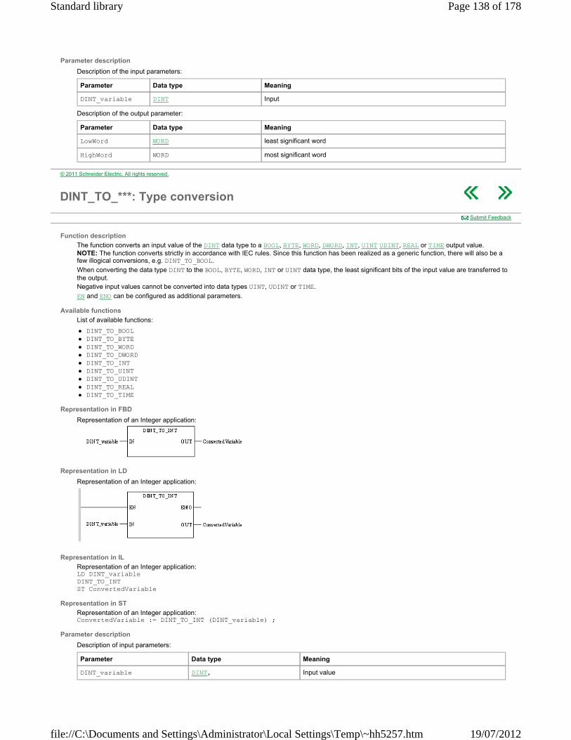
Parameter description
Description of the input parameters:
Description of the output parameter:
Parameter Data type Meaning
DINT_variable DINT Input
Parameter Data type Meaning
LowWord WORD least significant word
HighWord WORD most significant word
© 2011 Schneider Electric. All rights reserved.
DINT_TO_***: Type conversion
Function description
The function converts an input value of the DINT data type to a BOOL, BYTE, WORD, DWORD, INT, UINT UDINT, REAL or TIME output value. NOTE: The function converts strictly in accordance with IEC rules. Since this function has been realized as a generic function, there will also be a few illogical conversions, e.g. DINT_TO_BOOL.
When converting the data type DINT to the BOOL, BYTE, WORD, INT or UINT data type, the least significant bits of the input value are transferred to the output. Negative input values cannot be converted into data types UINT, UDINT or TIME.
EN and ENO can be configured as additional parameters.
Available functions
List of available functions:
DINT_TO_BOOL DINT_TO_BYTE DINT_TO_WORD DINT_TO_DWORD DINT_TO_INT DINT_TO_UINT DINT_TO_UDINT DINT_TO_REAL DINT_TO_TIME
Representation in FBD
Representation of an Integer application:
Representation in LD
Representation of an Integer application:
Representation in IL
Representation of an Integer application: LD DINT_variable DINT_TO_INT ST ConvertedVariable
Representation in ST
Representation of an Integer application: ConvertedVariable := DINT_TO_INT (DINT_variable) ;
Parameter description
Description of input parameters:
Submit Feedback
Parameter Data type Meaning
DINT_variable DINT, Input value
Page 138 of 178Standard library
19/07/2012file://C:\Documents and Settings\Administrator\Local Settings\Temp\~hh5257.htm
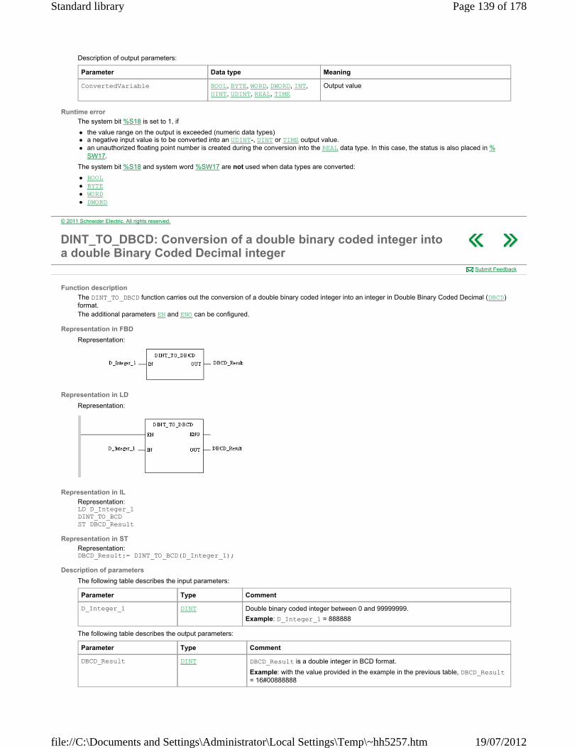
Description of output parameters:
Runtime error
The system bit %S18 is set to 1, if
the value range on the output is exceeded (numeric data types) a negative input value is to be converted into an UDINT-, UINT or TIME output value. an unauthorized floating point number is created during the conversion into the REAL data type. In this case, the status is also placed in %
SW17.
The system bit %S18 and system word %SW17 are not used when data types are converted:
BOOL BYTE WORD DWORD
Parameter Data type Meaning
ConvertedVariable BOOL, BYTE, WORD, DWORD, INT, UINT, UDINT, REAL, TIME
Output value
© 2011 Schneider Electric. All rights reserved.
DINT_TO_DBCD: Conversion of a double binary coded integer into a double Binary Coded Decimal integer
Function description
The DINT_TO_DBCD function carries out the conversion of a double binary coded integer into an integer in Double Binary Coded Decimal (DBCD) format. The additional parameters EN and ENO can be configured.
Representation in FBD
Representation:
Representation in LD
Representation:
Representation in IL
Representation: LD D_Integer_1 DINT_TO_BCD ST DBCD_Result
Representation in ST
Representation: DBCD_Result:= DINT_TO_BCD(D_Integer_1);
Description of parameters
The following table describes the input parameters:
The following table describes the output parameters:
Submit Feedback
Parameter Type Comment
D_Integer_1 DINT Double binary coded integer between 0 and 99999999.
Example: D_Integer_1 = 888888
Parameter Type Comment
DBCD_Result DINT DBCD_Result is a double integer in BCD format.
Example: with the value provided in the example in the previous table, DBCD_Result = 16#00888888
Page 139 of 178Standard library
19/07/2012file://C:\Documents and Settings\Administrator\Local Settings\Temp\~hh5257.htm

Runtime errors
The bit %S18 is set to 1 when the value to be converted is not a value between 0 and 99999999. The result of the function then returns the value of the input parameter.
© 2011 Schneider Electric. All rights reserved.
DT_TO_ARINT: Convert DT Variable to Integer Array
Function description
The function converts a DATE_AND_TIME (dt#) variable to an Integer Array of 4 elements with date and time in BCD format.
Example: If the input is:
DT_Variable = dt#2006-05-11-10:46:16
Then the output is:
DateAndTime_ARRAY[1] = 16#1600 DateAndTime_ARRAY[2] = 16#1046 DateAndTime_ARRAY[3] = 16#0511 DateAndTime_ARRAY[4] = 16#2006
EN and ENO can be configured as additional parameters.
Representation in FBD
Representation in LD
Representation in IL LD DT_Variable DT_TO_ARINT ST DateAndTime_ARRAY
Representation in ST DateAndTime_ARRAY := DT_TO_ARINT (DT_Variable) ;
Parameter description
Description of input parameters:
Description of output parameters:
Runtime errors
If the size of output DateAndTime_ARRAY is too small, ENO = 0 and OUT remains unchanged.
Submit Feedback
Parameter Data type Meaning
DT_Variable DT Date and time as DATE_AND_TIME (dt#) variable.
Parameter Data type Meaning
DateAndTime_ARRAY ARRAY [n..m] OF INT Integer ARRAY of 4 elements with the date and time in BCD format:
seconds,-- (16#ss,--)
corresponds to %SW50 hour, minute (16#hhmm)
corresponds to %SW51 month, day (16#mmdd)
corresponds to %SW52 year (16#yyyy)
corresponds to %SW53
© 2011 Schneider Electric. All rights reserved.
DT_TO_STRING: Conversion of a variable in DT format into a
Page 140 of 178Standard library
19/07/2012file://C:\Documents and Settings\Administrator\Local Settings\Temp\~hh5257.htm
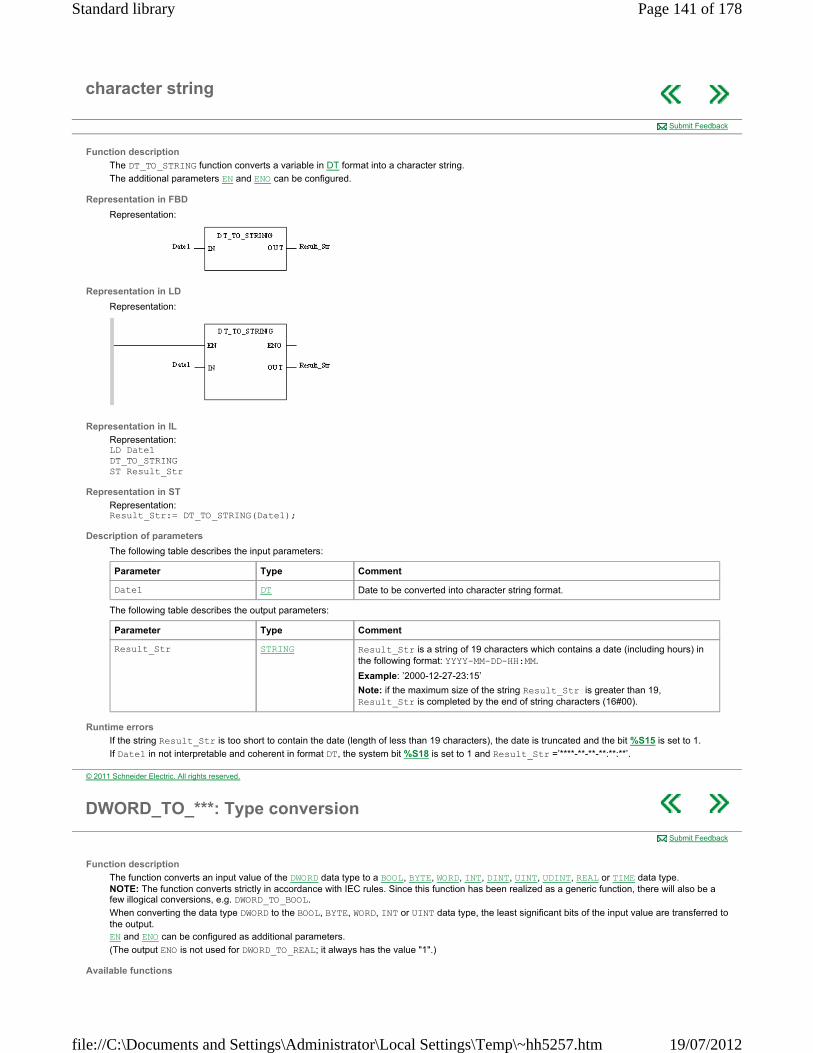
character string
Function description
The DT_TO_STRING function converts a variable in DT format into a character string.
The additional parameters EN and ENO can be configured.
Representation in FBD
Representation:
Representation in LD
Representation:
Representation in IL
Representation: LD Date1 DT_TO_STRING ST Result_Str
Representation in ST
Representation: Result_Str:= DT_TO_STRING(Date1);
Description of parameters
The following table describes the input parameters:
The following table describes the output parameters:
Runtime errors
If the string Result_Str is too short to contain the date (length of less than 19 characters), the date is truncated and the bit %S15 is set to 1.
If Date1 in not interpretable and coherent in format DT, the system bit %S18 is set to 1 and Result_Str =’****-**-**-**:**:**’.
Submit Feedback
Parameter Type Comment
Date1 DT Date to be converted into character string format.
Parameter Type Comment
Result_Str STRING Result_Str is a string of 19 characters which contains a date (including hours) in the following format: YYYY-MM-DD-HH:MM.
Example: ’2000-12-27-23:15’
Note: if the maximum size of the string Result_Str is greater than 19, Result_Str is completed by the end of string characters (16#00).
© 2011 Schneider Electric. All rights reserved.
DWORD_TO_***: Type conversion
Function description
The function converts an input value of the DWORD data type to a BOOL, BYTE, WORD, INT, DINT, UINT, UDINT, REAL or TIME data type. NOTE: The function converts strictly in accordance with IEC rules. Since this function has been realized as a generic function, there will also be a few illogical conversions, e.g. DWORD_TO_BOOL.
When converting the data type DWORD to the BOOL, BYTE, WORD, INT or UINT data type, the least significant bits of the input value are transferred to the output. EN and ENO can be configured as additional parameters.
(The output ENO is not used for DWORD_TO_REAL; it always has the value "1".)
Available functions
Submit Feedback
Page 141 of 178Standard library
19/07/2012file://C:\Documents and Settings\Administrator\Local Settings\Temp\~hh5257.htm

List of available functions:
DWORD_TO_BOOL DWORD_TO_BYTE DWORD_TO_WORD DWORD_TO_INT DWORD_TO_DINT DWORD_TO_UINT DWORD_TO_UDINT DWORD_TO_REAL DWORD_TO_TIME
Representation in FBD
Representation of an Integer application:
Representation in LD
Representation of an Integer application:
Representation in IL
Representation of an Integer application: LD DWORD_variable DWORD_TO_INT ST ConvertedVariable
Representation in ST
Representation of an Integer application: ConvertedVariable := DWORD_TO_INT (DWORD_variable) ;
Parameter description
Description of input parameters:
Description of output parameters:
Runtime error
Error handling is dependent on the function:
DWORD_TO_REAL The system bit %S18 is set to 1 and the status is stored in %SW17 , if an illegal floating-point decimal is generated during the conversion process.
all other Functions The system bit %S18 and system word %SW17 are not used.
Parameter Data type Meaning
DWORD_variable DWORD Input value
Parameter Data type Meaning
ConvertedVariable BOOL, BYTE, WORD, INT, DINT, UINT, UDINT, REAL, TIME
Output value
© 2011 Schneider Electric. All rights reserved.
GRAY_TO_INT: Conversion of an integer in Gray code into a binary coded integer
Function description
The GRAY_TO_INT function converts an integer expressed in GRAY code into a binary coded integer.
The additional parameters EN and ENO can be configured.
Representation in FBD
Representation:
Submit Feedback
Page 142 of 178Standard library
19/07/2012file://C:\Documents and Settings\Administrator\Local Settings\Temp\~hh5257.htm

Representation in LD
Representation:
Representation in IL
Representation: LD GRAY_Int GRAY_TO_INT ST Result_Int
Representation in ST
Representation: Result_Int:= GRAY_TO_INT(GRAY_Int);
Description of parameters
The following table describes the input parameters:
The following table describes the output parameters:
Parameter Type Comment
GRAY_Int INT Integer expressed in GRAY code.
Parameter Type Comment
Result_Int INT Result_Int is a binary coded integer.
© 2011 Schneider Electric. All rights reserved.
INT_AS_DINT: Concatenation of two integers to form a double integer
Function description
The INT_AS_DINT function concatenates two integers to form a double integer.
The additional parameters EN and ENO can be configured.
Representation in FBD
Representation:
Representation in LD
Representation:
Representation in IL
Representation: LD Low_Word INT_AS_DINT High_Word ST Double_Word
Representation in ST
Representation:
Submit Feedback
Page 143 of 178Standard library
19/07/2012file://C:\Documents and Settings\Administrator\Local Settings\Temp\~hh5257.htm
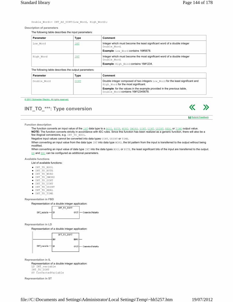
Double_Word:= INT_AS_DINT(Low_Word, High_Word);
Description of parameters
The following table describes the input parameters:
The following table describes the output parameters:
Parameter Type Comment
Low_Word INT Integer which must become the least significant word of a double integer Double_Word.
Example: Low_Word contains 16#5678.
High_Word INT Integer which must become the most significant word of a double integer Double_Word.
Example: High_Word contains 16#1234.
Parameter Type Comment
Double_Word DINT Double integer composed of two integers Low_Word for the least significant and High_Word for the most significant.
Example: for the values in the example provided in the previous table, Double_Word contains 16#12345678.
© 2011 Schneider Electric. All rights reserved.
INT_TO_***: Type conversion
Function description
The function converts an input value of the INT data type to a BOOL, BYTE, WORD, DWORD, DINT, UINT, UDINT, REAL or TIME output value. NOTE: The function converts strictly in accordance with IEC rules. Since this function has been realized as a generic function, there will also be a few illogical conversions, e.g. INT_TO_BOOL.
Negative input values cannot be converted into data types UINT, UDINT or TIME.
When converting an input value from the data type INT into data type WORD, the bit pattern from the input is transferred to the output without being modified. When converting an input value of data type INT into the data types BOOL or BYTE, the least significant bits of the input are transferred to the output.
EN and ENO can be configured as additional parameters.
Available functions
List of available functions:
INT_TO_BOOL INT_TO_BYTE INT_TO_WORD INT_TO_DWORD INT_TO_DINT INT_TO_UINT INT_TO_UDINT INT_TO_REAL INT_TO_TIME
Representation in FBD
Representation of a double integer application:
Representation in LD
Representation of a double integer application:
Representation in IL
Representation of a double integer application: LD INT_variable INT_TO_DINT ST ConvertedVariable
Representation in ST
Submit Feedback
Page 144 of 178Standard library
19/07/2012file://C:\Documents and Settings\Administrator\Local Settings\Temp\~hh5257.htm
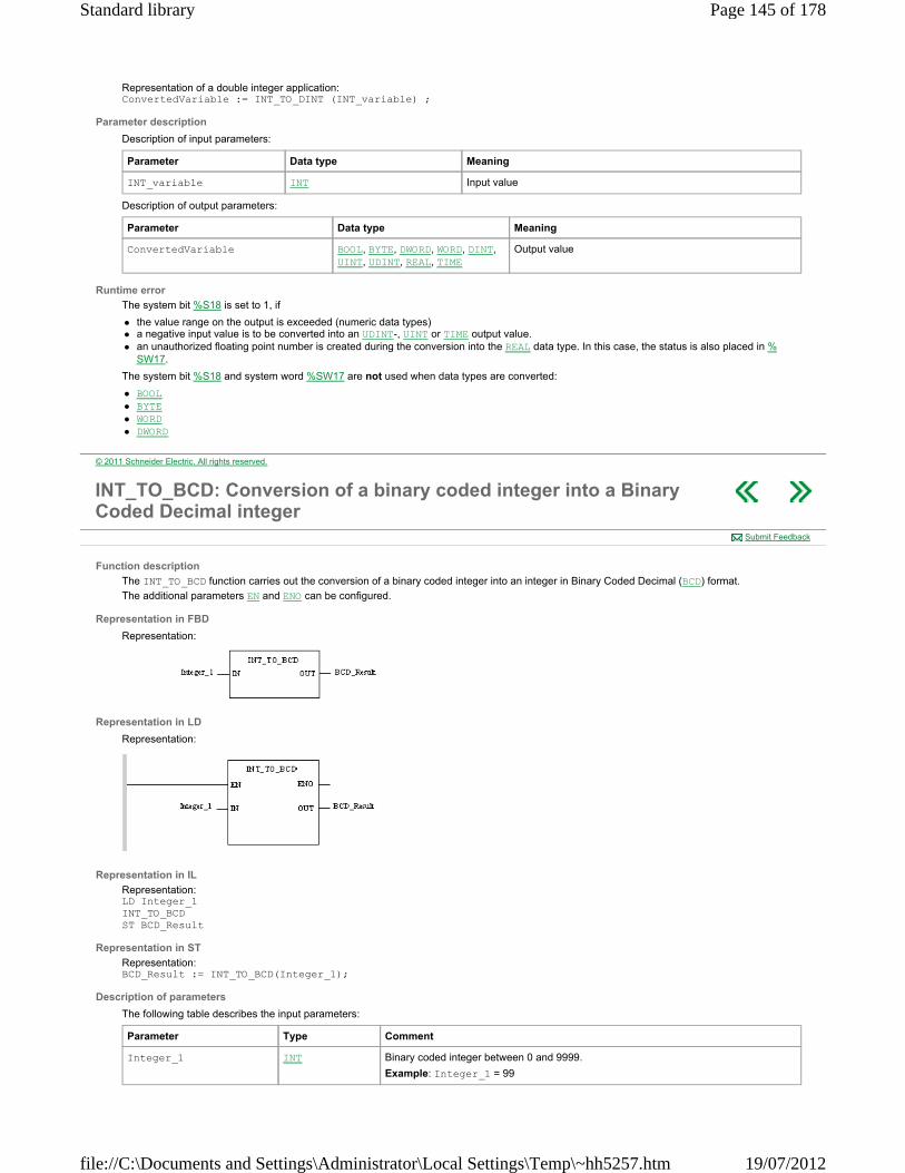
Representation of a double integer application: ConvertedVariable := INT_TO_DINT (INT_variable) ;
Parameter description
Description of input parameters:
Description of output parameters:
Runtime error
The system bit %S18 is set to 1, if
the value range on the output is exceeded (numeric data types) a negative input value is to be converted into an UDINT-, UINT or TIME output value. an unauthorized floating point number is created during the conversion into the REAL data type. In this case, the status is also placed in %
SW17.
The system bit %S18 and system word %SW17 are not used when data types are converted:
BOOL BYTE WORD DWORD
Parameter Data type Meaning
INT_variable INT Input value
Parameter Data type Meaning
ConvertedVariable BOOL, BYTE, DWORD, WORD, DINT, UINT, UDINT, REAL, TIME
Output value
© 2011 Schneider Electric. All rights reserved.
INT_TO_BCD: Conversion of a binary coded integer into a Binary Coded Decimal integer
Function description
The INT_TO_BCD function carries out the conversion of a binary coded integer into an integer in Binary Coded Decimal (BCD) format.
The additional parameters EN and ENO can be configured.
Representation in FBD
Representation:
Representation in LD
Representation:
Representation in IL
Representation: LD Integer_1 INT_TO_BCD ST BCD_Result
Representation in ST
Representation: BCD_Result := INT_TO_BCD(Integer_1);
Description of parameters
The following table describes the input parameters:
Submit Feedback
Parameter Type Comment
Integer_1 INT Binary coded integer between 0 and 9999.
Example: Integer_1 = 99
Page 145 of 178Standard library
19/07/2012file://C:\Documents and Settings\Administrator\Local Settings\Temp\~hh5257.htm

The following table describes the output parameters:
Runtime errors
The bit %S18 is set to 1 when the value to be converted is not a value between 0 and 9999. The result of the function then returns the value of the input parameter.
Parameter Type Comment
BCD_Result INT BCD_Result is a BCD integer.
Example: with the value provided in the example in the previous table, BCD_Result = 16#99
© 2011 Schneider Electric. All rights reserved.
INT_TO_DBCD: Conversion of a binary coded integer into a double Binary Coded Decimal integer
Function description
The INT_TO_DBCD function carries out the conversion of a binary coded integer into an integer in Double Binary Coded Decimal (DBCD) format. This function is useful when converting numbers with BCD coding greater than 32768. The additional parameters EN and ENO can be configured.
Representation in FBD
Representation:
Representation in LD
Representation:
Representation in IL
Representation: LD Integer_1 INT_TO_BCD ST DBCD_Result
Representation in ST
Representation: DBCD_Result:= INT_TO_BCD(Integer_1);
Description of parameters
The following table describes the input parameters:
The following table describes the output parameters:
Runtime errors
The bit %S18 is set to 1 when the value to be converted is not a value between 0 and 99999999 or when the value to be converted is negative. The result of the function then returns the value of the input parameter.
Submit Feedback
Parameter Type Comment
Integer_1 INT Binary coded integer between 0 and 32768.
Example: Integer_1 = 30000
Parameter Type Comment
DBCD_Result DINT DBCD_Result is a double integer in BCD format.
Example: with the value provided in the example in the previous table, DBCD_Result = 16#0030000
© 2011 Schneider Electric. All rights reserved.
Page 146 of 178Standard library
19/07/2012file://C:\Documents and Settings\Administrator\Local Settings\Temp\~hh5257.htm

RAD_TO_DEG: Conversion of radians to degrees
Function description
The RAD_TO_DEG function converts an angle expressed in radians into degrees.
The additional parameters EN and ENO can be configured.
Formula
The formula is as follows:
Representation in FBD
Representation:
Representation in LD
Representation:
Representation in IL
Representation: LD Angle_in_Radian RAD_TO_DEG ST Angle_in_Degree
Representation in ST
Representation: Angle_in_Degree:= RAD_TO_DEG(Angle_in_Radian);
Description of parameters
The following table describes the input parameters:
The following table describes the output parameters:
Runtime errors
When Angle_in_Degree is situated outside the interval ]-4096 π, 4096 π[, the system bit %S18 changes to 1 and the system bit %SW17 indicates the type of fault.
Submit Feedback
Parameter Type Comment
Angle_in_Radian REAL Value of Angle expressed in radians.
-4096π ≤ Angle_in_Radian ≤ +4096π
Parameter Type Comment
Angle_in_Degree REAL Angle expressed in degrees.
-360 < Angle_in_Degree < +360.
© 2011 Schneider Electric. All rights reserved.
REAL_AS_WORD: Type conversion
Function description
The procedure converts an input value of the REAL data type to 2 output values of the WORD data type.
The individual words of the REAL input are assigned to the outputs according to the output names.
EN and ENO can be configured as additional parameters.
Representation in FBD
Representation:
Submit Feedback
Page 147 of 178Standard library
19/07/2012file://C:\Documents and Settings\Administrator\Local Settings\Temp\~hh5257.htm

Representation in LD
Representation:
Representation in IL
Representation: LD REAL_variable REAL_AS_WORD LowWord, HighWord
Representation in ST
Representation: REAL_AS_WORD (REAL_variable, LowWord, HighWord);
Parameter description
Description of input parameters:
Description of output parameters:
Runtime error
The system bit %S18 is set to 1, if an unauthorized floating point number is set at the input.
Parameter Data type Meaning
REAL_variable REAL Input
Parameter Data type Meaning
LowWord WORD least significant word
HighWord WORD most significant word
© 2011 Schneider Electric. All rights reserved.
REAL_TO_***: Type conversion
Function description
The function converts an input value of the REAL data type to a BOOL, BYTE, WORD , DWORD, INT, DINT, UINT, UDINT data type or into the TIME data type. NOTE: The function converts strictly in accordance with IEC rules. Since this function has been realized as a generic function, there will also be a few illogical conversions, e.g. REAL_TO_BOOL.
When converting to BOOL, BYTE, WORD, the least significant bits of the input value are transferred to the output. A runtime error message is not given and ENO remains 1.
When converting to INT, DINT, UINT, UDINT and TIME, the IEC 559 rules for rounding are applied.
EN and ENO can be configured as additional parameters.
(The output ENO is not used for REAL_TO_BOOL, REAL_TO_BYTE, REAL_TO_WORD and REAL_TO_DWORD; it always has the value "1".)
Available functions
List of available functions:
REAL_TO_BOOL REAL_TO_BYTE REAL_TO_WORD REAL_TO_DWORD REAL_TO_INT REAL_TO_DINT REAL_TO_UINT REAL_TO_UDINT REAL_TO_TIME
Example
The following example shows how the IEC 559 rounding is applied. 1,4 -> 1 1,5 -> 2
Submit Feedback
Page 148 of 178Standard library
19/07/2012file://C:\Documents and Settings\Administrator\Local Settings\Temp\~hh5257.htm
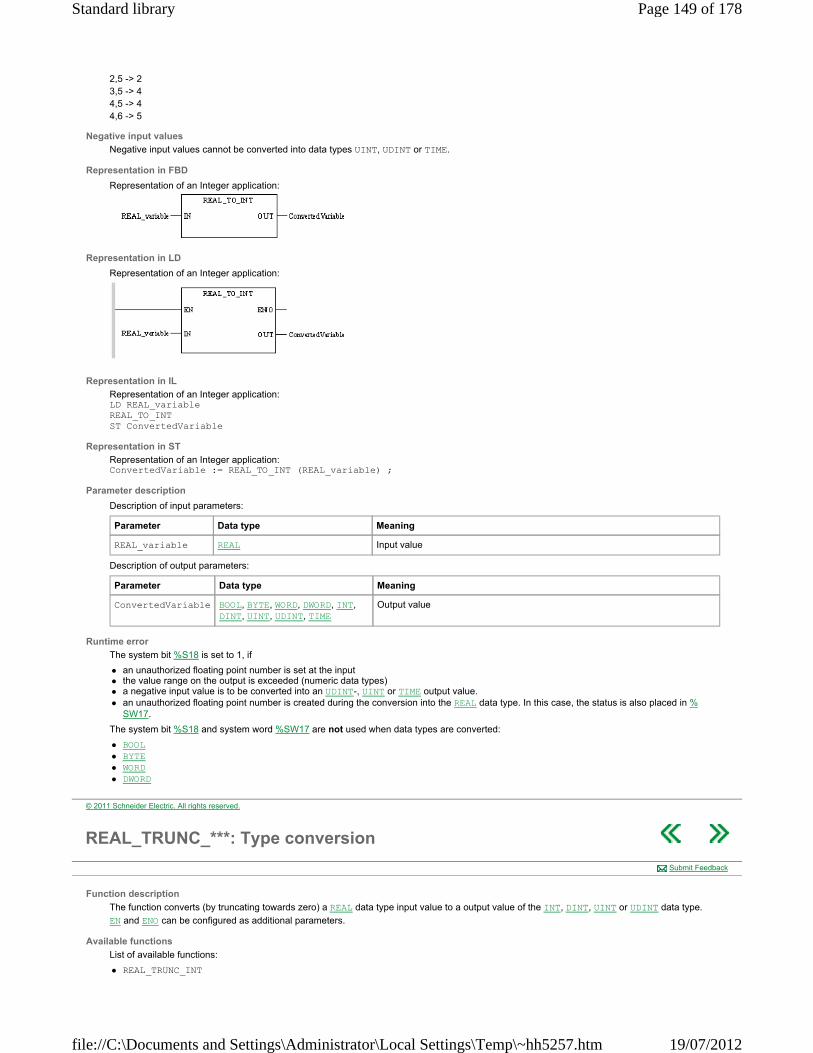
2,5 -> 2 3,5 -> 4 4,5 -> 4 4,6 -> 5
Negative input values
Negative input values cannot be converted into data types UINT, UDINT or TIME.
Representation in FBD
Representation of an Integer application:
Representation in LD
Representation of an Integer application:
Representation in IL
Representation of an Integer application: LD REAL_variable REAL_TO_INT ST ConvertedVariable
Representation in ST
Representation of an Integer application: ConvertedVariable := REAL_TO_INT (REAL_variable) ;
Parameter description
Description of input parameters:
Description of output parameters:
Runtime error
The system bit %S18 is set to 1, if
an unauthorized floating point number is set at the input the value range on the output is exceeded (numeric data types) a negative input value is to be converted into an UDINT-, UINT or TIME output value. an unauthorized floating point number is created during the conversion into the REAL data type. In this case, the status is also placed in %
SW17.
The system bit %S18 and system word %SW17 are not used when data types are converted:
BOOL BYTE WORD DWORD
Parameter Data type Meaning
REAL_variable REAL Input value
Parameter Data type Meaning
ConvertedVariable BOOL, BYTE, WORD, DWORD, INT, DINT, UINT, UDINT, TIME
Output value
© 2011 Schneider Electric. All rights reserved.
REAL_TRUNC_***: Type conversion
Function description
The function converts (by truncating towards zero) a REAL data type input value to a output value of the INT, DINT, UINT or UDINT data type.
EN and ENO can be configured as additional parameters.
Available functions
List of available functions:
REAL_TRUNC_INT
Submit Feedback
Page 149 of 178Standard library
19/07/2012file://C:\Documents and Settings\Administrator\Local Settings\Temp\~hh5257.htm

REAL_TRUNC_DINT REAL_TRUNC_UINT REAL_TRUNC_UDINT
Example
The following example shows the converting procedure. 1,6 -> 1 -1,6 -> -1 1,4 -> 1 -1,4 -> -1
Data type
Negative input values cannot be converted into data types UDINT or UINT.
Representation in FBD
Representation of an Integer application:
Representation in LD
Representation of an Integer application:
Representation in IL
Representation of an Integer application: LD REAL_variable REAL_TRUNC_INT ST ConvertedVariable
Representation in ST
Representation of an Integer application: ConvertedVariable := REAL_TRUNC_INT (REAL_variable) ;
Parameter description
Description of the input parameters:
Description of the output parameter:
Runtime error
The system bit %S18 is set to 1 and the status is stored in %SW17 if
a negative input value is to be converted into an UDINT or UINT output value or
an unauthorized floating point number is set at the input.
Parameter Data type Meaning
REAL_variable REAL Input value
Parameter Data type Meaning
ConvertedVariable INT, DINT, UINT, UDINT Output value
© 2011 Schneider Electric. All rights reserved.
STRING_TO_ASCII: Type conversion
Function description
The function copies the string from the data type STRING at the input (without conversion) as ASCII values into the INT array at the output.
This function is used to transfer different characters (all correspond with ASCII values 16#01... 16#FF). The only exception is 16#00 (Value 0). It is used to fill in empty (unused) bits. Since each ASCII character only requires 1 Byte, 2 ASCII characters can be transferred per Integer element of the output array. The transfer sequence is high byte, low byte.
Submit Feedback
Page 150 of 178Standard library
19/07/2012file://C:\Documents and Settings\Administrator\Local Settings\Temp\~hh5257.htm
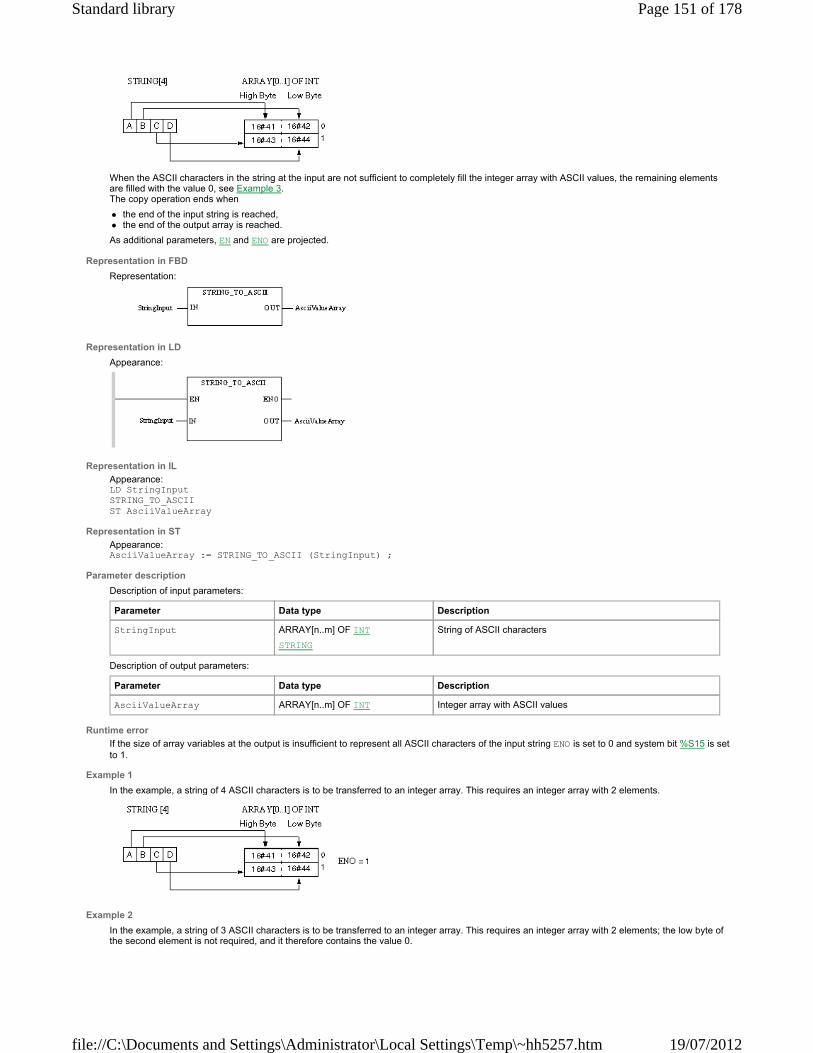
When the ASCII characters in the string at the input are not sufficient to completely fill the integer array with ASCII values, the remaining elements are filled with the value 0, see Example 3. The copy operation ends when
the end of the input string is reached, the end of the output array is reached.
As additional parameters, EN and ENO are projected.
Representation in FBD
Representation:
Representation in LD
Appearance:
Representation in IL
Appearance: LD StringInput STRING_TO_ASCII ST AsciiValueArray
Representation in ST
Appearance: AsciiValueArray := STRING_TO_ASCII (StringInput) ;
Parameter description
Description of input parameters:
Description of output parameters:
Runtime error
If the size of array variables at the output is insufficient to represent all ASCII characters of the input string ENO is set to 0 and system bit %S15 is set to 1.
Example 1
In the example, a string of 4 ASCII characters is to be transferred to an integer array. This requires an integer array with 2 elements.
Example 2
In the example, a string of 3 ASCII characters is to be transferred to an integer array. This requires an integer array with 2 elements; the low byte of the second element is not required, and it therefore contains the value 0.
Parameter Data type Description
StringInput ARRAY[n..m] OF INT
STRING
String of ASCII characters
Parameter Data type Description
AsciiValueArray ARRAY[n..m] OF INT Integer array with ASCII values
Page 151 of 178Standard library
19/07/2012file://C:\Documents and Settings\Administrator\Local Settings\Temp\~hh5257.htm

Example 3
When the ASCII characters in the string at the input are not sufficient to completely fill the integer array with ASCII values, the remaining elements are filled with the value 0.
Example 4
When an empty string is transferred, the elements of the integer array are filled with the value 0 .
Example 5
In the example, 8 ASCII characters are to be transferred. Since the output array is too small for that, ENO is set to 0 and Systembit %S15 is set to 1.
© 2011 Schneider Electric. All rights reserved.
STRING_TO_ASCII_INV: Type conversion
Function description
The function copies the string from the data type STRING at the input (without conversion) as ASCII values into the INT array at the output.
This function is used to transfer different characters (all correspond with ASCII values 16#01... 16#FF). The only exception is 16#00 (Value 0). It is used to fill in empty (unused) bits. Since each ASCII character only requires 1 Byte, 2 ASCII characters can be transferred per Integer element of the output array. The transfer sequence is low byte, high byte.
Submit Feedback
Page 152 of 178Standard library
19/07/2012file://C:\Documents and Settings\Administrator\Local Settings\Temp\~hh5257.htm
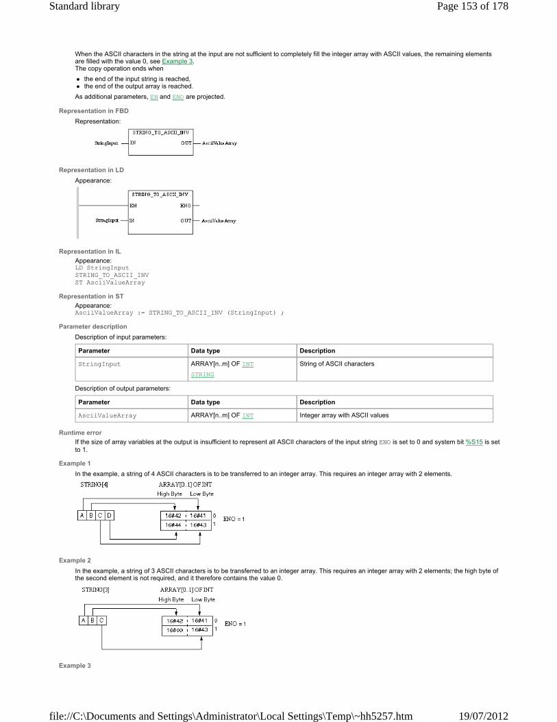
When the ASCII characters in the string at the input are not sufficient to completely fill the integer array with ASCII values, the remaining elements are filled with the value 0, see Example 3. The copy operation ends when
the end of the input string is reached, the end of the output array is reached.
As additional parameters, EN and ENO are projected.
Representation in FBD
Representation:
Representation in LD
Appearance:
Representation in IL
Appearance: LD StringInput STRING_TO_ASCII_INV ST AsciiValueArray
Representation in ST
Appearance: AsciiValueArray := STRING_TO_ASCII_INV (StringInput) ;
Parameter description
Description of input parameters:
Description of output parameters:
Runtime error
If the size of array variables at the output is insufficient to represent all ASCII characters of the input string ENO is set to 0 and system bit %S15 is set to 1.
Example 1
In the example, a string of 4 ASCII characters is to be transferred to an integer array. This requires an integer array with 2 elements.
Example 2
In the example, a string of 3 ASCII characters is to be transferred to an integer array. This requires an integer array with 2 elements; the high byte of the second element is not required, and it therefore contains the value 0.
Example 3
Parameter Data type Description
StringInput ARRAY[n..m] OF INT
STRING
String of ASCII characters
Parameter Data type Description
AsciiValueArray ARRAY[n..m] OF INT Integer array with ASCII values
Page 153 of 178Standard library
19/07/2012file://C:\Documents and Settings\Administrator\Local Settings\Temp\~hh5257.htm
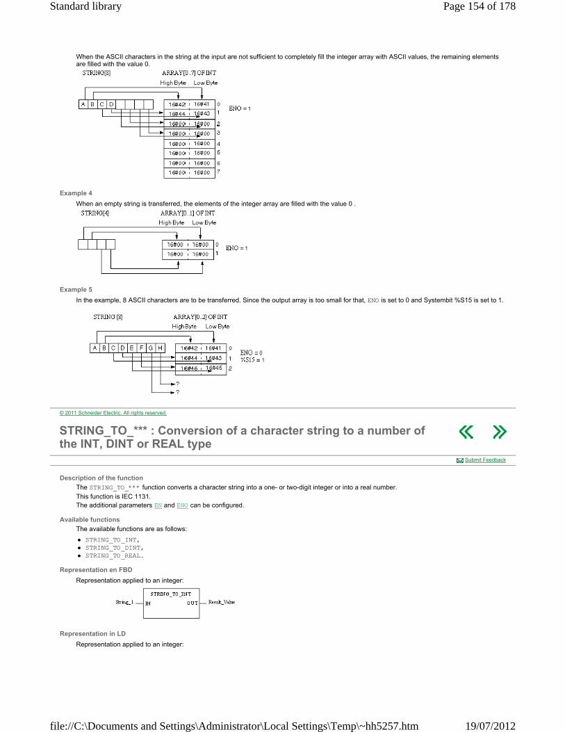
When the ASCII characters in the string at the input are not sufficient to completely fill the integer array with ASCII values, the remaining elements are filled with the value 0.
Example 4
When an empty string is transferred, the elements of the integer array are filled with the value 0 .
Example 5
In the example, 8 ASCII characters are to be transferred. Since the output array is too small for that, ENO is set to 0 and Systembit %S15 is set to 1.
© 2011 Schneider Electric. All rights reserved.
STRING_TO_*** : Conversion of a character string to a number of the INT, DINT or REAL type
Description of the function
The STRING_TO_*** function converts a character string into a one- or two-digit integer or into a real number.
This function is IEC 1131. The additional parameters EN and ENO can be configured.
Available functions
The available functions are as follows:
STRING_TO_INT, STRING_TO_DINT, STRING_TO_REAL.
Representation en FBD
Representation applied to an integer:
Representation in LD
Representation applied to an integer:
Submit Feedback
Page 154 of 178Standard library
19/07/2012file://C:\Documents and Settings\Administrator\Local Settings\Temp\~hh5257.htm
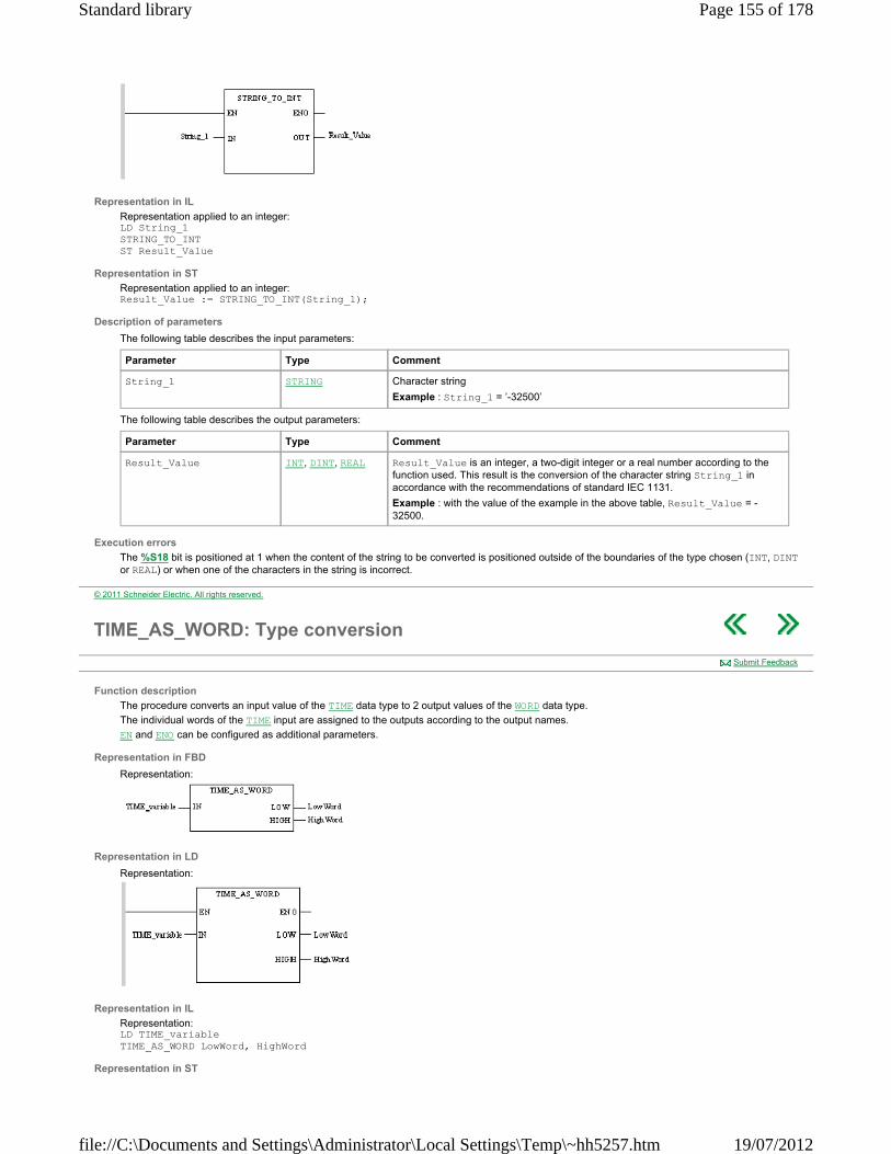
Representation in IL
Representation applied to an integer: LD String_1 STRING_TO_INT ST Result_Value
Representation in ST
Representation applied to an integer: Result_Value := STRING_TO_INT(String_1);
Description of parameters
The following table describes the input parameters:
The following table describes the output parameters:
Execution errors
The %S18 bit is positioned at 1 when the content of the string to be converted is positioned outside of the boundaries of the type chosen (INT, DINT or REAL) or when one of the characters in the string is incorrect.
Parameter Type Comment
String_1 STRING Character string
Example : String_1 = ’-32500’
Parameter Type Comment
Result_Value INT, DINT, REAL Result_Value is an integer, a two-digit integer or a real number according to the function used. This result is the conversion of the character string String_1 in accordance with the recommendations of standard IEC 1131.
Example : with the value of the example in the above table, Result_Value = -32500.
© 2011 Schneider Electric. All rights reserved.
TIME_AS_WORD: Type conversion
Function description
The procedure converts an input value of the TIME data type to 2 output values of the WORD data type.
The individual words of the TIME input are assigned to the outputs according to the output names.
EN and ENO can be configured as additional parameters.
Representation in FBD
Representation:
Representation in LD
Representation:
Representation in IL
Representation: LD TIME_variable TIME_AS_WORD LowWord, HighWord
Representation in ST
Submit Feedback
Page 155 of 178Standard library
19/07/2012file://C:\Documents and Settings\Administrator\Local Settings\Temp\~hh5257.htm
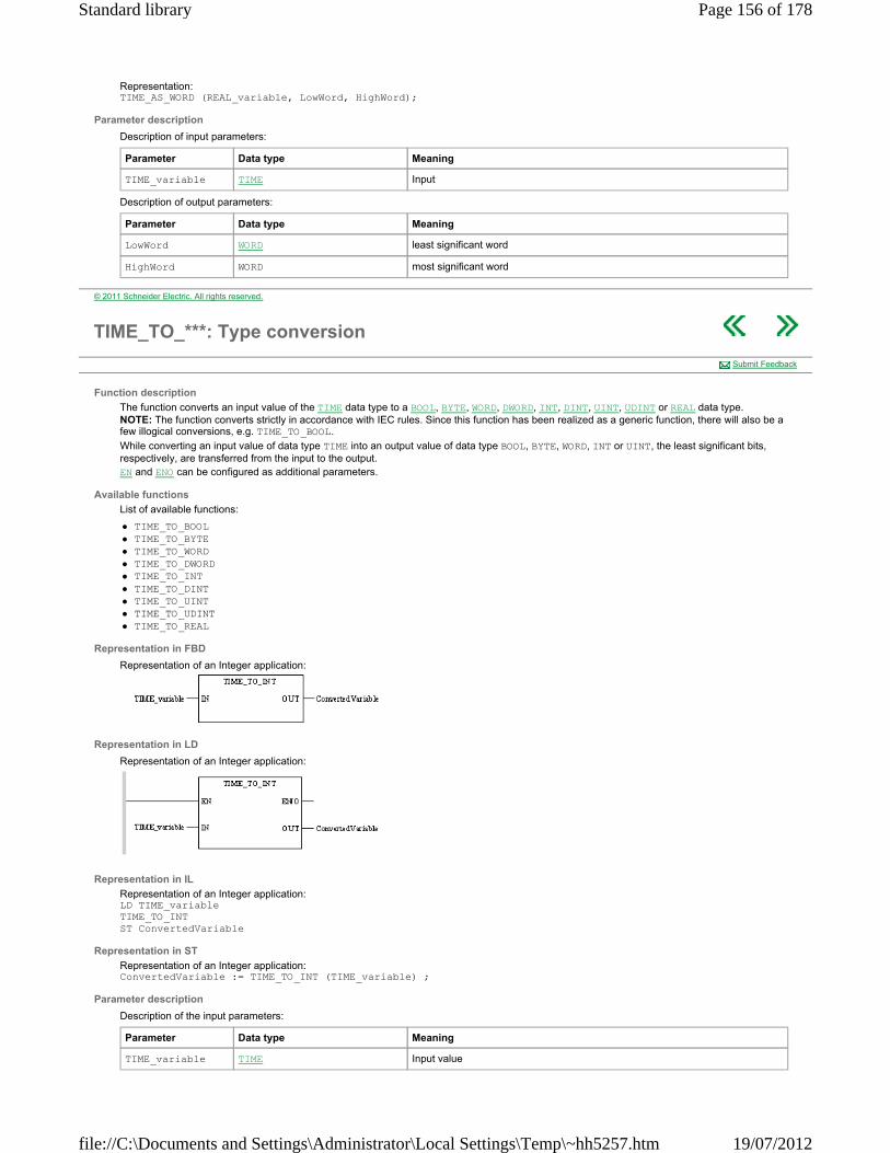
Representation: TIME_AS_WORD (REAL_variable, LowWord, HighWord);
Parameter description
Description of input parameters:
Description of output parameters:
Parameter Data type Meaning
TIME_variable TIME Input
Parameter Data type Meaning
LowWord WORD least significant word
HighWord WORD most significant word
© 2011 Schneider Electric. All rights reserved.
TIME_TO_***: Type conversion
Function description
The function converts an input value of the TIME data type to a BOOL, BYTE, WORD, DWORD, INT, DINT, UINT, UDINT or REAL data type. NOTE: The function converts strictly in accordance with IEC rules. Since this function has been realized as a generic function, there will also be a few illogical conversions, e.g. TIME_TO_BOOL.
While converting an input value of data type TIME into an output value of data type BOOL, BYTE, WORD, INT or UINT, the least significant bits, respectively, are transferred from the input to the output. EN and ENO can be configured as additional parameters.
Available functions
List of available functions:
TIME_TO_BOOL TIME_TO_BYTE TIME_TO_WORD TIME_TO_DWORD TIME_TO_INT TIME_TO_DINT TIME_TO_UINT TIME_TO_UDINT TIME_TO_REAL
Representation in FBD
Representation of an Integer application:
Representation in LD
Representation of an Integer application:
Representation in IL
Representation of an Integer application: LD TIME_variable TIME_TO_INT ST ConvertedVariable
Representation in ST
Representation of an Integer application: ConvertedVariable := TIME_TO_INT (TIME_variable) ;
Parameter description
Description of the input parameters:
Submit Feedback
Parameter Data type Meaning
TIME_variable TIME Input value
Page 156 of 178Standard library
19/07/2012file://C:\Documents and Settings\Administrator\Local Settings\Temp\~hh5257.htm
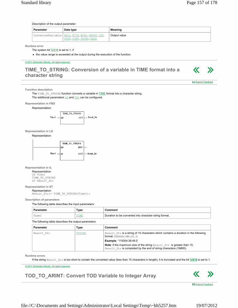
Description of the output parameter:
Runtime error
The system bit %S18 is set to 1, if
the value range is exceeded at the output during the execution of the function.
Parameter Data type Meaning
ConvertedVariable BOOL, BYTE, WORD, DWORD, INT, DINT, UINT, UDINT, REAL
Output value
© 2011 Schneider Electric. All rights reserved.
TIME_TO_STRING: Conversion of a variable in TIME format into a character string
Function description
The TIME_TO_STRING function converts a variable in TIME format into a character string.
The additional parameters EN and ENO can be configured.
Representation in FBD
Representation:
Representation in LD
Representation:
Representation in IL
Representation: LD Time1 TIME_TO_STRING ST Result_Str
Representation in ST
Representation: Result_Str:= TIME_TO_STRING(Time1);
Description of parameters
The following table describes the input parameters:
The following table describes the output parameters:
Runtime errors
If the string Result_Str is too short to contain the converted value (less than 15 characters in length), it is truncated and the bit %S15 is set to 1.
Submit Feedback
Parameter Type Comment
Time1 TIME Duration to be converted into character string format.
Parameter Type Comment
Result_Str STRING Result_Str is a string of 15 characters which contains a duration in the following format: HHHHHH:MM:SS.D.
Example: ’119304:38:49.5’
Note: if the maximum size of the string Result_Str is greater than 15, Result_Str is completed by the end of string characters (16#00).
© 2011 Schneider Electric. All rights reserved.
TOD_TO_ARINT: Convert TOD Variable to Integer Array
Submit Feedback
Page 157 of 178Standard library
19/07/2012file://C:\Documents and Settings\Administrator\Local Settings\Temp\~hh5257.htm

Function description
The function converts a TIME_OF_DAY (tod#) variable to an Integer Array of 2 elements with the time of day in BCD format.
Example: If the input is:
TOD_Variable = tod#10:46:16
Then the output is:
Time_ARRAY[1] = 16#1600 Time_ARRAY[2] = 16#1046
EN and ENO can be configured as additional parameters.
Representation in FBD
Representation in LD
Representation in IL LD TOD_Variable TOD_TO_ARINT ST Time_ARRAY
Representation in ST Time_ARRAY := TOD_TO_ARINT (TOD_Variable) ;
Parameter description
Description of input parameters:
Description of output parameters:
Runtime errors
If the size of output Time_ARRAY is too small, ENO = 0 and OUT remains unchanged.
Parameter Data type Meaning
TOD_Variable TIME_OF_DAY Time of day as TIME_OF_DAY (tod#) variable.
Parameter Data type Meaning
Time_ARRAY ARRAY [n..m] OF INT Integer ARRAY of 2 elements with the date and time in BCD format:
seconds,-- (16#ss,--),
corresponds to %SW50 hour, minute (16#hhmm)
corresponds to %SW51
© 2011 Schneider Electric. All rights reserved.
TOD_TO_STRING: Conversion of a variable in TOD format into a character string
Function description
The TOD_TO_STRING function converts a variable in TOD format into a character string.
The additional parameters EN and ENO can be configured.
Representation in FBD
Representation:
Representation in LD
Submit Feedback
Page 158 of 178Standard library
19/07/2012file://C:\Documents and Settings\Administrator\Local Settings\Temp\~hh5257.htm
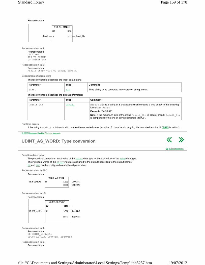
Representation:
Representation in IL
Representation: LD Time1 TOD_TO_STRING ST Result_Str
Representation in ST
Representation: Result_Str:= =TOD_TO_STRING(Time1);
Description of parameters
The following table describes the input parameters:
The following table describes the output parameters:
Runtime errors
If the string Result_Str is too short to contain the converted value (less than 8 characters in length), it is truncated and the bit %S15 is set to 1.
Parameter Type Comment
Time1 TOD Time of day to be converted into character string format.
Parameter Type Comment
Result_Str STRING Result_Str is a string of 8 characters which contains a time of day in the following format: HH:MM:SS.
Example: ’04:38:49’
Note: if the maximum size of the string Result_Str is greater than 8, Result_Str is completed by the end of string characters (16#00).
© 2011 Schneider Electric. All rights reserved.
UDINT_AS_WORD: Type conversion
Function description
The procedure converts an input value of the UDINT data type to 2 output values of the WORD data type.
The individual words of the UDINT input are assigned to the outputs according to the output names.
EN and ENO can be configured as additional parameters.
Representation in FBD
Representation:
Representation in LD
Representation:
Representation in IL
Representation: LD UDINT_variable UDINT_AS_WORD LowWord, HighWord
Representation in ST
Representation:
Submit Feedback
Page 159 of 178Standard library
19/07/2012file://C:\Documents and Settings\Administrator\Local Settings\Temp\~hh5257.htm
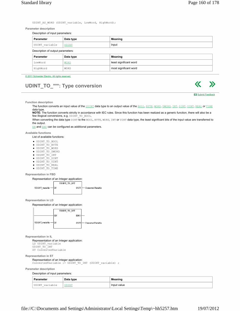
UDINT_AS_WORD (UDINT_variable, LowWord, HighWord);
Parameter description
Description of input parameters:
Description of output parameters:
Parameter Data type Meaning
UDINT_variable UDINT Input
Parameter Data type Meaning
LowWord WORD least significant word
HighWord WORD most significant word
© 2011 Schneider Electric. All rights reserved.
UDINT_TO_***: Type conversion
Function description
The function converts an input value of the UDINT data type to an output value of the BOOL, BYTE, WORD, DWORD, INT, DINT, UINT, REAL or TIME data type. NOTE: The function converts strictly in accordance with IEC rules. Since this function has been realized as a generic function, there will also be a few illogical conversions, e.g. UDINT_TO_BOOL.
When converting the data type DINT to the BOOL, BYTE, WORD, INT or UINT data type, the least significant bits of the input value are transferred to the output. EN and ENO can be configured as additional parameters.
Available functions
List of available functions:
UDINT_TO_BOOL UDINT_TO_BYTE UDINT_TO_WORD UDINT_TO_DWORD UDINT_TO_INT UDINT_TO_DINT UDINT_TO_UINT UDINT_TO_REAL UDINT_TO_TIME
Representation in FBD
Representation of an Integer application:
Representation in LD
Representation of an Integer application:
Representation in IL
Representation of an Integer application: LD UDINT_variable UDINT_TO_INT ST ConvertedVariable
Representation in ST
Representation of an Integer application: ConvertedVariable := UDINT_TO_INT (UDINT_variable) ;
Parameter description
Description of input parameters:
Submit Feedback
Parameter Data type Meaning
UDINT_variable UDINT Input value
Page 160 of 178Standard library
19/07/2012file://C:\Documents and Settings\Administrator\Local Settings\Temp\~hh5257.htm

Description of output parameters:
Runtime error
The system bit %S18 is set to 1, if
the value range on the output is exceeded (numeric data types) a negative input value is to be converted into an UDINT-, UINT or TIME output value. an unauthorized floating point number is created during the conversion into the REAL data type. In this case, the status is also placed in %
SW17.
The system bit %S18 and system word %SW17 are not used when data types are converted:
BOOL BYTE WORD DWORD
Parameter Data type Meaning
ConvertedVariable BOOL, BYTE, WORD, DWORD, INT, DINT, UINT, REAL, TIME
Output value
© 2011 Schneider Electric. All rights reserved.
UINT_TO_***: Type conversion
Function description
The function converts an input value of the UINT data type to an output value of the BOOL, BYTE, WORD, DWORD, INT, DINT, UDINT, REAL or TIME.data type. NOTE: The function converts strictly in accordance with IEC rules. Since this function has been realized as a generic function, there will also be a few illogical conversions, e.g. UINT_TO_BOOL.
When converting an input value from the data type UINT into data type WORD, the bit pattern from the input is transferred to the output without being modified. When converting an input value of data type UINT into the data types BOOL or BYTE, the least significant bits of the input are transferred to the output. EN and ENO can be configured as additional parameters.
Available functions
List of available functions:
UINT_TO_BOOL UINT_TO_BYTE UINT_TO_WORD UINT_TO_DWORD UINT_TO_INT UINT_TO_DINT UINT_TO_UDINT UINT_TO_REAL UINT_TO_TIME
Representation in FBD
Representation of an Integer application:
Representation in LD
Representation of an Integer application:
Representation in IL
Representation of an Integer application: LD UINT_variable UINT_TO_INT ST ConvertedVariable
Representation in ST
Representation of an Integer application: ConvertedVariable := UINT_TO_INT (UINT_variable) ;
Submit Feedback
Page 161 of 178Standard library
19/07/2012file://C:\Documents and Settings\Administrator\Local Settings\Temp\~hh5257.htm
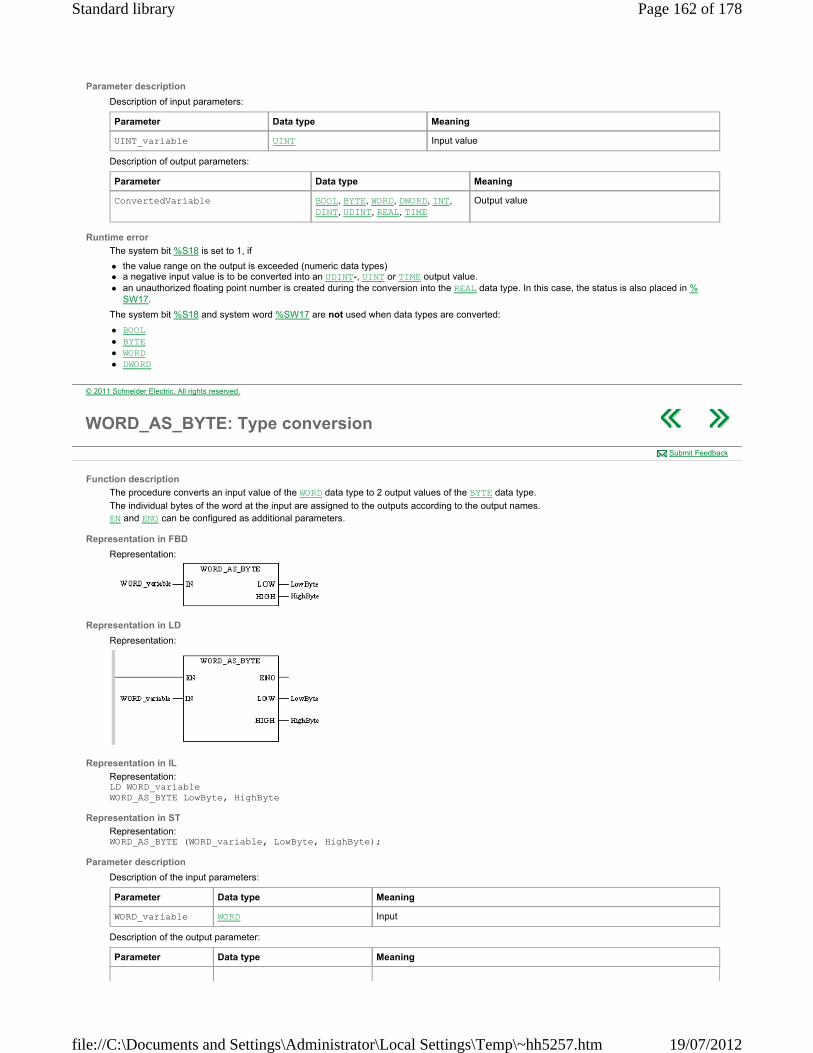
Parameter description
Description of input parameters:
Description of output parameters:
Runtime error
The system bit %S18 is set to 1, if
the value range on the output is exceeded (numeric data types) a negative input value is to be converted into an UDINT-, UINT or TIME output value. an unauthorized floating point number is created during the conversion into the REAL data type. In this case, the status is also placed in %
SW17.
The system bit %S18 and system word %SW17 are not used when data types are converted:
BOOL BYTE WORD DWORD
Parameter Data type Meaning
UINT_variable UINT Input value
Parameter Data type Meaning
ConvertedVariable BOOL, BYTE, WORD, DWORD, INT, DINT, UDINT, REAL, TIME
Output value
© 2011 Schneider Electric. All rights reserved.
WORD_AS_BYTE: Type conversion
Function description
The procedure converts an input value of the WORD data type to 2 output values of the BYTE data type.
The individual bytes of the word at the input are assigned to the outputs according to the output names. EN and ENO can be configured as additional parameters.
Representation in FBD
Representation:
Representation in LD
Representation:
Representation in IL
Representation: LD WORD_variable WORD_AS_BYTE LowByte, HighByte
Representation in ST
Representation: WORD_AS_BYTE (WORD_variable, LowByte, HighByte);
Parameter description
Description of the input parameters:
Description of the output parameter:
Submit Feedback
Parameter Data type Meaning
WORD_variable WORD Input
Parameter Data type Meaning
Page 162 of 178Standard library
19/07/2012file://C:\Documents and Settings\Administrator\Local Settings\Temp\~hh5257.htm
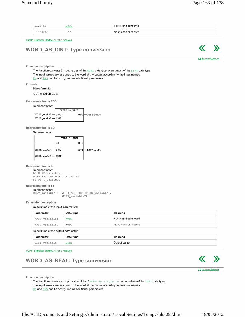
LowByte BYTE least significant byte
HighByte BYTE most significant byte
© 2011 Schneider Electric. All rights reserved.
WORD_AS_DINT: Type conversion
Function description
The function converts 2 input values of the WORD data type to an output of the DINT data type.
The input values are assigned to the word at the output according to the input names. EN and ENO can be configured as additional parameters.
Formula
Block formula:
Representation in FBD
Representation:
Representation in LD
Representation:
Representation in IL
Representation: LD WORD_variable1 WORD_AS_DINT WORD_variable2 ST DINT_variable
Representation in ST
Representation: DINT_variable := WORD_AS_DINT (WORD_variable1, WORD_variable2) ;
Parameter description
Description of the input parameters:
Description of the output parameter:
Submit Feedback
Parameter Data type Meaning
WORD_variable1 WORD least significant word
WORD_variable2 WORD most significant word
Parameter Data type Meaning
DINT_variable DINT Output value
© 2011 Schneider Electric. All rights reserved.
WORD_AS_REAL: Type conversion
Function description
The function converts an input value of the 2 WORD data type to output values of the REAL data type.
The input values are assigned to the word at the output according to the input names. EN and ENO can be configured as additional parameters.
Submit Feedback
Page 163 of 178Standard library
19/07/2012file://C:\Documents and Settings\Administrator\Local Settings\Temp\~hh5257.htm

Formula
Block formula:
Representation in FBD
Representation:
Representation in LD
Representation:
Representation in IL
Representation: LD WORD_variable1 WORD_AS_REAL WORD_variable2 ST REAL_Output
Representation in ST
Representation: REAL_Output := WORD_AS_REAL (WORD_variable1, WORD_variable2);
Parameter description
Description of input parameters:
Description of output parameters:
Runtime error
The system bit %S18 is set to 1, if
an unauthorized floating-point number is set at the input an unauthorized floating-point number is created during the conversion into the REAL data type. In this case, the status is also placed in %
SW17.
Parameter Data type Meaning
WORD_variable1 WORD least significant byte
WORD_variable2 WORD most significant byte
Parameter Data type Meaning
REAL_Output REAL Output value
© 2011 Schneider Electric. All rights reserved.
WORD_AS_TIME: Type conversion
Function description
The function converts 2 input values of the WORD data type to an output value of the TIME data type.
The input values are assigned to the word at the output according to the input names. EN and ENO can be configured as additional parameters.
Formula
Block formula:
Representation in FBD
Representation:
Submit Feedback
Page 164 of 178Standard library
19/07/2012file://C:\Documents and Settings\Administrator\Local Settings\Temp\~hh5257.htm
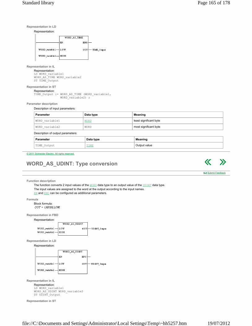
Representation in LD
Representation:
Representation in IL
Representation: LD WORD_variable1 WORD_AS_TIME WORD_variable2 ST TIME_Output
Representation in ST
Representation: TIME_Output := WORD_AS_TIME (WORD_variable1, WORD_variable2) ;
Parameter description
Description of input parameters:
Description of output parameters:
Parameter Data type Meaning
WORD_variable1 WORD least significant byte
WORD_variable2 WORD most significant byte
Parameter Data type Meaning
TIME_Output TIME Output value
© 2011 Schneider Electric. All rights reserved.
WORD_AS_UDINT: Type conversion
Function description
The function converts 2 input values of the WORD data type to an output value of the UDINT data type.
The input values are assigned to the word at the output according to the input names. EN and ENO can be configured as additional parameters.
Formula
Block formula:
Representation in FBD
Representation:
Representation in LD
Representation:
Representation in IL
Representation: LD WORD_variable1 WORD_AS_UDINT WORD_variable2 ST UDINT_Output
Representation in ST
Submit Feedback
Page 165 of 178Standard library
19/07/2012file://C:\Documents and Settings\Administrator\Local Settings\Temp\~hh5257.htm

Representation: UDINT_Output := WORD_AS_UDINT (WORD_variable1, WORD_variable2) ;
Parameter description
Description of input parameters:
Description of output parameters:
Parameter Data type Meaning
WORD_variable1 WORD least significant byte
WORD_variable2 WORD most significant byte
Parameter Data type Meaning
UDINT_Output UDINT Output value
© 2011 Schneider Electric. All rights reserved.
WORD_TO_BIT: Type conversion
Function description
The procedure converts an input value of the WORD data type to 16 output values of the BOOL data type.
The individual bits of the word at the input are assigned to the outputs according to the output names.
EN and ENO can be configured as additional parameters.
Representation in FBD
Representation:
Representation in LD
Representation:
Representation in IL
Representation: LD WORD_variable WORD_TO_BIT BOOL_variable1, BOOL_variable2, BOOL_variable3, BOOL_variable4, BOOL_variable5, BOOL_variable6, BOOL_variable7, BOOL_variable8, BOOL_variable9, BOOL_variable10, BOOL_variable11, BOOL_variable12, BOOL_variable13, BOOL_variable14, BOOL_variable15, BOOL_variable16
Representation in ST
Representation: WORD_TO_BIT (WORD_variable, BOOL_variable1 BOOL_variable2, BOOL_variable3, BOOL_variable4, BOOL_variable5, BOOL_variable6, BOOL_variable7, BOOL_variable8, BOOL_variable9, BOOL_variable10,
Submit Feedback
Page 166 of 178Standard library
19/07/2012file://C:\Documents and Settings\Administrator\Local Settings\Temp\~hh5257.htm
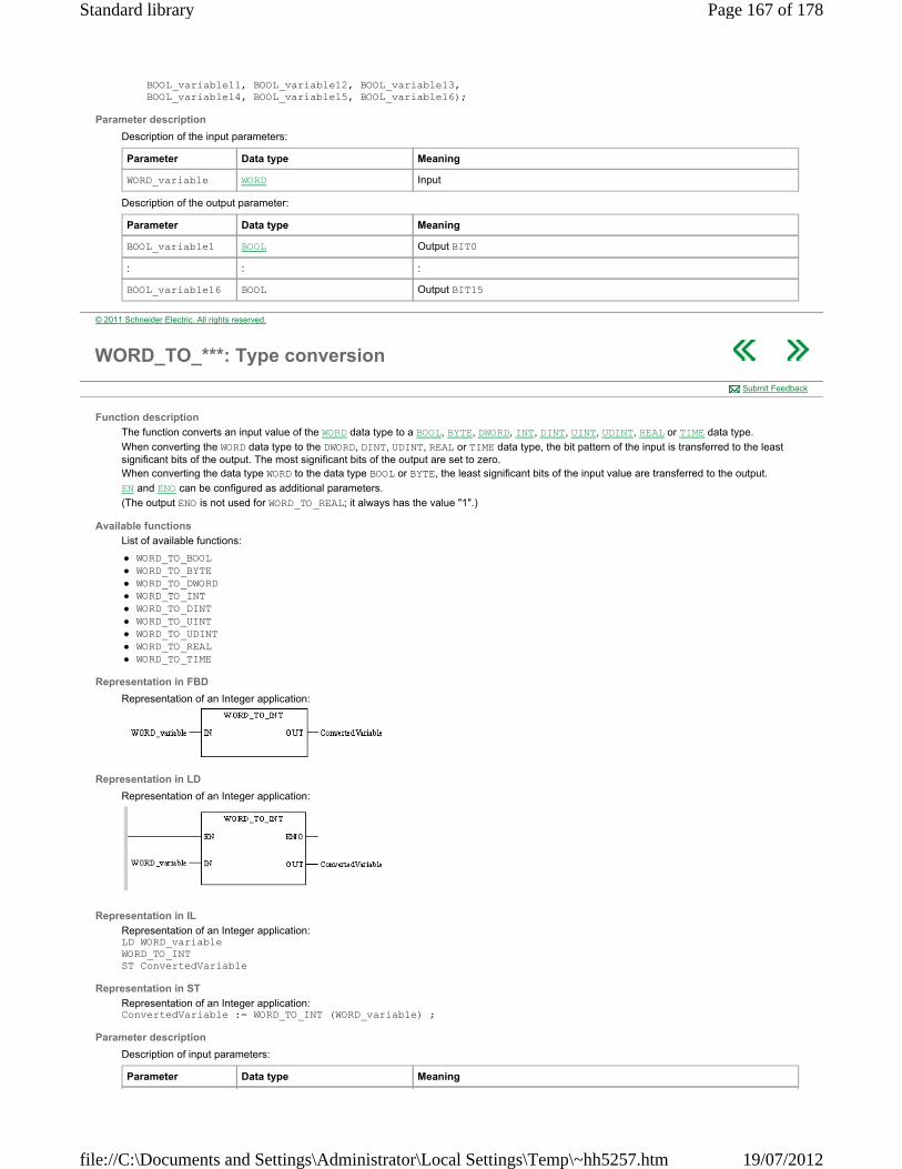
BOOL_variable11, BOOL_variable12, BOOL_variable13, BOOL_variable14, BOOL_variable15, BOOL_variable16);
Parameter description
Description of the input parameters:
Description of the output parameter:
Parameter Data type Meaning
WORD_variable WORD Input
Parameter Data type Meaning
BOOL_variable1 BOOL Output BIT0
: : :
BOOL_variable16 BOOL Output BIT15
© 2011 Schneider Electric. All rights reserved.
WORD_TO_***: Type conversion
Function description
The function converts an input value of the WORD data type to a BOOL, BYTE, DWORD, INT, DINT, UINT, UDINT, REAL or TIME data type.
When converting the WORD data type to the DWORD, DINT, UDINT, REAL or TIME data type, the bit pattern of the input is transferred to the least significant bits of the output. The most significant bits of the output are set to zero. When converting the data type WORD to the data type BOOL or BYTE, the least significant bits of the input value are transferred to the output.
EN and ENO can be configured as additional parameters.
(The output ENO is not used for WORD_TO_REAL; it always has the value "1".)
Available functions
List of available functions:
WORD_TO_BOOL WORD_TO_BYTE WORD_TO_DWORD WORD_TO_INT WORD_TO_DINT WORD_TO_UINT WORD_TO_UDINT WORD_TO_REAL WORD_TO_TIME
Representation in FBD
Representation of an Integer application:
Representation in LD
Representation of an Integer application:
Representation in IL
Representation of an Integer application: LD WORD_variable WORD_TO_INT ST ConvertedVariable
Representation in ST
Representation of an Integer application: ConvertedVariable := WORD_TO_INT (WORD_variable) ;
Parameter description
Description of input parameters:
Submit Feedback
Parameter Data type Meaning
Page 167 of 178Standard library
19/07/2012file://C:\Documents and Settings\Administrator\Local Settings\Temp\~hh5257.htm

Description of output parameters:
Runtime error
The system bit %S18 is set to 1 and the status is stored in %SW17 if
an unauthorized floating-point number is created during the conversion into the REAL data type.
WORD_variable WORD Input value
Parameter Data type Meaning
ConvertedVariable BOOL, BYTE, DWORD, INT, DINT, UINT, UDINT, REAL, TIME
Output value
© 2011 Schneider Electric. All rights reserved.
***_TO_STRING: Conversion of a variable into a character string
Function description
The ***_TO_STRING function converts an INT, DINT or REAL variable into a character string.
The additional parameters EN and ENO can be configured.
Available functions
The available functions are as follows:
INT_TO_STRING, DINT_TO_STRING, REAL_TO_STRING.
Representation in FBD
Representation applied to a real:
Representation in LD
Representation applied to a real:
Representation in IL
Representation applied to a real: LD Value1 REAL_TO_STRING ST Result_Str
Representation in ST
Representation applied to a real: Result_Str:= REAL_TO_STRING(Value1);
Description of parameters
The following table describes the input parameters:
The following table describes the output parameters:
Submit Feedback
Parameter Type Comment
Value1 INT , DINT, REAL Variable to be converted into character string format.
Parameter Type Comment
Result_Str STRING Result_Str is a character string whose length depends on the type of Value1:
5 figures plus the sign making 6 characters for one INT (example: ’-00045’), 10 figures plus the sign, making 11 characters for one DINT (example: ’-
0000678911’),
Note: under PL7, the result is on 11 figures plus the sign, making 12 characters for one DINT (example: ’-00006789110’).
14 characters for a REAL (example:
’-3.1234560e+25’).
Page 168 of 178Standard library
19/07/2012file://C:\Documents and Settings\Administrator\Local Settings\Temp\~hh5257.htm

Runtime errors
If, during the conversion of a value of REAL type, Value1 is not between -3.402824e+38 and -1.175494e-38 or +1.175494e-38 and +3.402824e+38, the bit %S18 is set to 1 and the contents of the string Result_Str is not significant.
© 2011 Schneider Electric. All rights reserved.
Appendices
Overview
This section contains the appendicies.
What's in this Appendix?
The appendix contains the following chapters:
EFB Error Codes and Values System Objects
© 2011 Schneider Electric. All rights reserved.
EFB Error Codes and Values
Introduction
The following tables show the error codes and error values created for the EFBs of the Base Library.
What's in this Chapter?
This chapter contains the following topics:
Tables of Error Codes for the Base Library Common Floating Point Errors
© 2011 Schneider Electric. All rights reserved.
Tables of Error Codes for the Base Library
Introduction
The following tables show the error codes and error values created for the EFBs of the Base Library.
Date & Time
Table of error codes and errors values created for EFBs of the Date & Time family.
Submit Feedback
EFB name Error code ENO state in case of error
Error value in Dec
Error value in Hex
Error description
DIVTIME E_DIVIDE_BY_ZERO F -30176 16#8A20 Divide by zero
DIVTIME E_NEGATIVE_INPUT_ FOR_TIME_OPERATION
F -30177 16#8A1F A negative value cannot be converted to data type TIME
DIVTIME E_ARITHMETIC_ ERROR F -30170 16#8A26 Arithmetic error
DIVTIME E_ERR_ARITHMETIC F -30003 16#8ACD Arithmetic overflow (%S18 set)
DIVTIME FP_ERROR F - - See table Common Floating Point Errors
MULTIME E_ERR_ARITHMETIC F -30003 16#8ACD Arithmetic overflow (%S18 set)
MULTIME E_ARITHMETIC_ERROR_MUL_OV F -30172 16#8A24 Arithmetic error / Muliplication overflow
MULTIME E_ARITHMETIC_ERROR_ADD_OV F -30173 16#8A23 Arithmetic error / Addition overflow
MULTIME E_ARITHMETIC_ERROR_BIG_PAR F -30171 16#8A25 Arithmetic error / Parameter exceeds range
MULTIME E_NEGATIVE_INPUT_FOR_TIME_OPERATION F -30177 16#8A1F A negative value cannot be converted to data type TIME
MULTIME FP_ERROR F - - See table Common Floating Point Errors
Page 169 of 178Standard library
19/07/2012file://C:\Documents and Settings\Administrator\Local Settings\Temp\~hh5257.htm
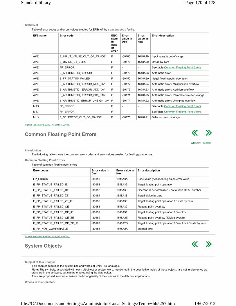
Statistical
Table of error codes and errors values created for EFBs of the Statistical family.
EFB name Error code ENO state in case of error
Error value in Dec
Error value in Hex
Error description
AVE E_INPUT_VALUE_OUT_OF_RANGE F -30183 16#8A19 Input value is out of range
AVE E_DIVIDE_BY_ZERO F -30176 16#8A20 Divide by zero
AVE FP_ERROR F - - See table Common Floating Point Errors
AVE E_ARITHMETIC_ ERROR F -30170 16#8A26 Arithmetic error
AVE E_FP_STATUS_FAILED F -30150 16#8A3A Illegal floating point operation
AVE E_ARITHMETIC_ ERROR_MUL_OV F -30172 16#8A24 Arithmetic error / Muliplication overflow
AVE E_ARITHMETIC_ ERROR_ADD_OV F -30173 16#8A23 Arithmetic error / Addition overflow
AVE E_ARITHMETIC_ ERROR_BIG_PAR F -30171 16#8A25 Arithmetic error / Parameter exceeds range
AVE E_ARITHMETIC_ERROR_UNSIGN_OV F -30174 16#8A22 Arithmetic error / Unsigned overflow
MAX FP_ERROR F - - See table Common Floating Point Errors
MIN FP_ERROR F - - See table Common Floating Point Errors
MUX E_SELECTOR_OUT_OF_RANGE F -30175 16#8A21 Selector is out of range
© 2011 Schneider Electric. All rights reserved.
Common Floating Point Errors
Introduction
The following table shows the commen error codes and error values created for floating point errors.
Common Floating Point Errors
Table of common floating point errors
Submit Feedback
Error codes Error value in Dec
Error value in Hex
Error description
FP_ERROR -30150 16#8A3A Base value (not apearing as an error value)
E_FP_STATUS_FAILED_IE -30151 16#8A39 Illegal floating point operation
E_FP_STATUS_FAILED_DE -30152 16#8A38 Operand is denormalized - not a valid REAL number
E_FP_STATUS_FAILED_ZE -30154 16#8A36 Illegal divide by zero
E_FP_STATUS_FAILED_ZE_IE -30155 16#8A35 Illegal floating point operation / Divide by zero
E_FP_STATUS_FAILED_OE -30158 16#8A32 Floating point overflow
E_FP_STATUS_FAILED_OE_IE -30159 16#8A31 Illegal floating point operation / Overflow
E_FP_STATUS_FAILED_OE_ZE -30162 16#8A2E Floating point overflow / Divide by zero
E_FP_STATUS_FAILED_OE_ZE_IE -30163 16#8A2D Illegal floating point operation / Overflow / Divide by zero
E_FP_NOT_COMPARABLE -30166 16#8A2A Internal error
© 2011 Schneider Electric. All rights reserved.
System Objects
Subject of this Chapter
This chapter describes the system bits and words of Unity Pro language. Note: The symbols, associated with each bit object or system word, mentioned in the descriptive tables of these objects, are not implemented as standard in the software, but can be entered using the data editor. They are proposed in order to ensure the homogeneity of their names in the different applications.
What's in this Chapter?
Page 170 of 178Standard library
19/07/2012file://C:\Documents and Settings\Administrator\Local Settings\Temp\~hh5257.htm

This chapter contains the following topics:
System Bit Introduction Description of System Bits %S9 to %S13 Description of System Bits %S15 to %S21 Description of System Words %SW12 to %SW29 Description of System Words %SW48 to %SW59
© 2011 Schneider Electric. All rights reserved.
System Bit Introduction
General
The Modicon M340, Premium, Atrium and Quantum PLCs use %Si system bits which indicate the state of the PLC, or they can be used to control how it operates. These bits can be tested in the user program to detect any functional development requiring a set processing procedure. Some of these bits must be reset to their initial or normal state by the program. However, the system bits that are reset to their initial or normal state by the system must not be reset by the program or by the terminal.
See: Related Topics Submit Feedback
© 2011 Schneider Electric. All rights reserved.
Description of System Bits %S9 to %S13
Detailed Description
Description of system bits %S9 to %S13:
Submit Feedback
Bit
Symbol
Function Description Initial state
Modicon M340
Premium Atrium
Quantum
%S9
OUTDIS
Outputs set to the fallback position on all buses
Normally at 0, this bit is set to 1 by the program or the terminal:
set to 1: sets the bit to 0 or maintains the current value depending on the chosen configuration (X bus, Fipio, AS-i, etc.).
set to 0: outputs are updated normally.
Note: The system bit acts directly on the physical outputs and not on the image bits of the outputs.
Note: On Modicon M340, ethernet I/O scanner and Global Data are affected by the %S9 bit.
(1) Note: On Modicon M340, inputs/outputs distributed via CANopen bus are not affected by the %S9 bit.
On Modicon M340, after an operating mode, outputs are in security mode state equal to 0 while the bit is set.
0 YES (1) YES NO
%S10
IOERR
Input/output fault
Normally at 1, this bit is set to 0 when a fault on an in-rack module or device on Fipio is detected (e.g. non-compliant configuration, exchange fault, hardware fault, etc.). The %S10 bit is reset to 1 by the system as soon as the fault disappears.
1 YES YES YES
CAUTION UNEXPECTED APPLICATION BEHAVIOR - SPECIFIC VARIABLE BEHAVIOR
On Quantum, network communication errors with remote devices detected by communication modules (NOM, NOE, NWM, CRA, CRP) and motion mo(MMS) are not reported on bits %S10, %S16 ans %S119.
Failure to follow these instructions can result in injury or equipment damage.
Bit
Symbol
Function Description Initial state
Modicon M340
Premium Atrium
Quantum
%S11
WDG
Watchdog overflow
Normally at 0, this is set to 1 by the system as soon as the task execution time becomes greater than the maximum execution time (i.e. the watchdog) declared in the task properties.
0 YES YES YES
%S12
PLCRUNNING
PLC in RUN This bit is set to 1 by the system when the PLC is in RUN.
It is set to 0 by the system as soon as the PLC is no longer in RUN (STOP, INIT, etc.).
0 YES YES YES
Page 171 of 178Standard library
19/07/2012file://C:\Documents and Settings\Administrator\Local Settings\Temp\~hh5257.htm

%S13
1RSTSCANRUN
First cycle after switching to RUN
Switching the PLC from STOP mode to RUN mode (including after a cold start with automatic start in run) is indicated by setting system bit %S13 to 1. This bit is reset to 0 at the end of the first cycle of the MAST task in RUN mode.
- YES YES YES
© 2011 Schneider Electric. All rights reserved.
Description of System Bits %S15 to %S21
Detailed Description
Description of system bits %S15 to %S21:
See: Related Topics Submit Feedback
Bit
Symbol
Function Description Initial state
Modicon M340
Premium Atrium
Quantum
%S15
STRINGERROR
Character string fault
Normally set to 0, this bit is set to 1 when the destination zone for a character string transfer is not of sufficient size (including the number of characters and the end of string character) to receive this character string.
The application stops in error state if the %S78 bit has been to set to 1.
This bit must be reset to 0 by the application.
This bit is not available on Quantum safety PLCs.
0 YES YES YES
(except for safety PLCs)
%S16
IOERRTSK
Task input/output fault
Normally set to 1, this bit is set to 0 by the system when a fault on an in-rack module or device on Fipio is detected (e.g. non-compliant configuration, exchange fault, hardware fault, etc.).
This bit must be reset to 1 by the user.
1 YES YES YES
CAUTION UNEXPECTED APPLICATION BEHAVIOR - SPECIFIC VARIABLE BEHAVIOR
On Quantum, network communication errors with remote devices detected by communication modules (NOM, NOE, NWM, CRA, CRP) and motion mo(MMS) are not reported on bits %S10, %S16 and %S119.
Failure to follow these instructions can result in injury or equipment damage.
Bit
Symbol
Function Description Initial state
Modicon M340
Premium Atrium
Quantum
%S17
CARRY
Rotate shift output
Normally at 0.
During a rotate shift operation, this bit takes the state of the outgoing bit.
0 YES YES YES
%S18
OVERFLOW
Overflow or arithmetic error
Normally set to 0, this bit is set to 1 in the event of a capacity overflow if there is:
a result greater than + 32 767 or less than - 32 768, in single length,
result greater than + 65 535, in unsigned integer, a result greater than + 2 147 483 647 or less than -
2 147 483 648, in double length, result greater than +4 294 967 296, in double length
or unsigned integer, real values outside limits, division by 0, the root of a negative number, forcing to a non-existent step on a drum, stacking up of an already full register, emptying of
an already empty register.
There is only one case for which bit %S18 is not raised by the Modicon M340 PLCs when real values are outside limits. It is only if denormalized operands or some operations which generate denormalized results are used (gradual underflow).
It must be tested by the user program after each operation where there is a risk of overflow, then reset to 0 by the user if there is indeed an overflow.
When the %S18 bit switches to 1, the application stops in error state if the %S78 bit has been to set to 1.
0 YES YES YES
%S19 Task period Normally set to 0, this bit is set to 1 by the system in the 0 YES YES YES
Page 172 of 178Standard library
19/07/2012file://C:\Documents and Settings\Administrator\Local Settings\Temp\~hh5257.htm
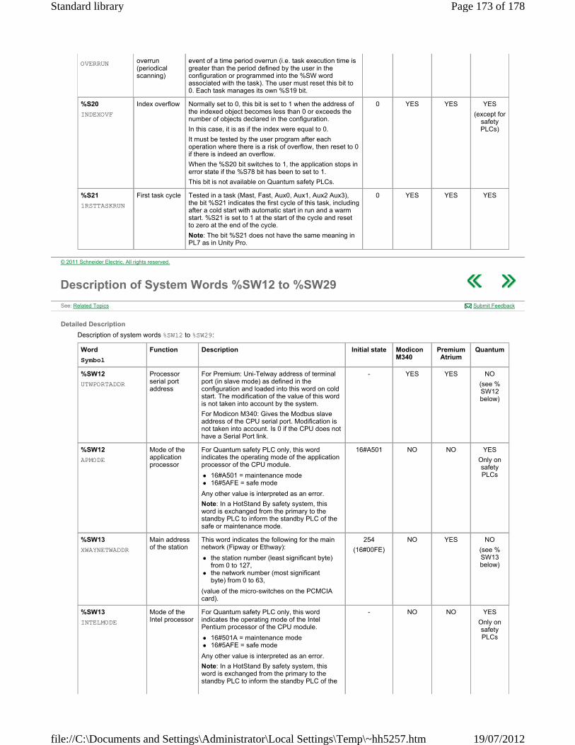
OVERRUN overrun (periodical scanning)
event of a time period overrun (i.e. task execution time is greater than the period defined by the user in the configuration or programmed into the %SW word associated with the task). The user must reset this bit to 0. Each task manages its own %S19 bit.
%S20
INDEXOVF
Index overflow Normally set to 0, this bit is set to 1 when the address of the indexed object becomes less than 0 or exceeds the number of objects declared in the configuration.
In this case, it is as if the index were equal to 0.
It must be tested by the user program after each operation where there is a risk of overflow, then reset to 0 if there is indeed an overflow.
When the %S20 bit switches to 1, the application stops in error state if the %S78 bit has been to set to 1.
This bit is not available on Quantum safety PLCs.
0 YES YES YES
(except for safety PLCs)
%S21
1RSTTASKRUN
First task cycle Tested in a task (Mast, Fast, Aux0, Aux1, Aux2 Aux3), the bit %S21 indicates the first cycle of this task, including after a cold start with automatic start in run and a warm start. %S21 is set to 1 at the start of the cycle and reset to zero at the end of the cycle.
Note: The bit %S21 does not have the same meaning in PL7 as in Unity Pro.
0 YES YES YES
© 2011 Schneider Electric. All rights reserved.
Description of System Words %SW12 to %SW29
Detailed Description
Description of system words %SW12 to %SW29:
See: Related Topics Submit Feedback
Word
Symbol
Function Description Initial state Modicon M340
Premium Atrium
Quantum
%SW12
UTWPORTADDR
Processor serial port address
For Premium: Uni-Telway address of terminal port (in slave mode) as defined in the configuration and loaded into this word on cold start. The modification of the value of this word is not taken into account by the system.
For Modicon M340: Gives the Modbus slave address of the CPU serial port. Modification is not taken into account. Is 0 if the CPU does not have a Serial Port link.
- YES YES NO
(see %SW12 below)
%SW12
APMODE
Mode of the application processor
For Quantum safety PLC only, this word indicates the operating mode of the application processor of the CPU module.
16#A501 = maintenance mode 16#5AFE = safe mode
Any other value is interpreted as an error.
Note: In a HotStand By safety system, this word is exchanged from the primary to the standby PLC to inform the standby PLC of the safe or maintenance mode.
16#A501 NO NO YES
Only on safety PLCs
%SW13
XWAYNETWADDR
Main address of the station
This word indicates the following for the main network (Fipway or Ethway):
the station number (least significant byte) from 0 to 127,
the network number (most significant byte) from 0 to 63,
(value of the micro-switches on the PCMCIA card).
254
(16#00FE)
NO YES NO
(see %SW13 below)
%SW13
INTELMODE
Mode of the Intel processor
For Quantum safety PLC only, this word indicates the operating mode of the Intel Pentium processor of the CPU module.
16#501A = maintenance mode 16#5AFE = safe mode
Any other value is interpreted as an error.
Note: In a HotStand By safety system, this word is exchanged from the primary to the standby PLC to inform the standby PLC of the
- NO NO YES
Only on safety PLCs
Page 173 of 178Standard library
19/07/2012file://C:\Documents and Settings\Administrator\Local Settings\Temp\~hh5257.htm
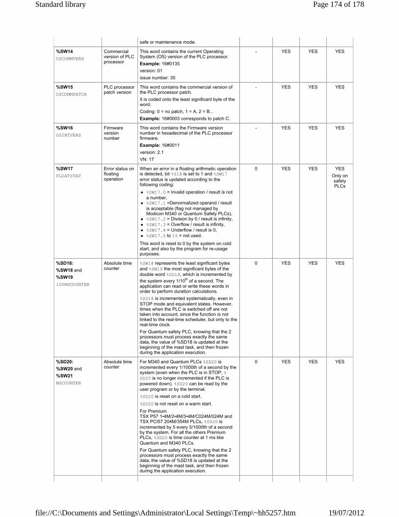
safe or maintenance mode.
%SW14
OSCOMMVERS
Commercial version of PLC processor
This word contains the current Operating System (OS) version of the PLC processor.
Example: 16#0135
version: 01
issue number: 35
- YES YES YES
%SW15
OSCOMMPATCH
PLC processor patch version
This word contains the commercial version of the PLC processor patch.
It is coded onto the least significant byte of the word.
Coding: 0 = no patch, 1 = A, 2 = B...
Example: 16#0003 corresponds to patch C.
- YES YES YES
%SW16
OSINTVERS
Firmware version number
This word contains the Firmware version number in hexadecimal of the PLC processor firmware.
Example: 16#0011
version: 2.1
VN: 17
- YES YES YES
%SW17
FLOATSTAT
Error status on floating operation
When an error in a floating arithmetic operation is detected, bit %S18 is set to 1 and %SW17 error status is updated according to the following coding:
%SW17.0 = Invalid operation / result is not a number,
%SW17.1 =Denormalized operand / result is acceptable (flag not managed by Modicon M340 or Quantum Safety PLCs),
%SW17.2 = Division by 0 / result is infinity, %SW17.3 = Overflow / result is infinity, %SW17.4 = Underflow / result is 0, %SW17.5 to 15 = not used.
This word is reset to 0 by the system on cold start, and also by the program for re-usage purposes.
0 YES YES YES
Only on safety PLCs
%SD18:
%SW18 and
%SW19
100MSCOUNTER
Absolute time counter
%SW18 represents the least significant bytes and %SW19 the most significant bytes of the double word %SD18, which is incremented by
the system every 1/10th of a second. The application can read or write these words in order to perform duration calculations.
%SD18 is incremented systematically, even in STOP mode and equivalent states. However, times when the PLC is switched off are not taken into account, since the function is not linked to the real-time scheduler, but only to the real-time clock.
For Quantum safety PLC, knowing that the 2 processors must process exactly the same data, the value of %SD18 is updated at the beginning of the mast task, and then frozen during the application execution.
0 YES YES YES
%SD20:
%SW20 and
%SW21
MSCOUNTER
Absolute time counter
For M340 and Quantum PLCs %SD20 is incremented every 1/1000th of a second by the system (even when the PLC is in STOP, %SD20 is no longer incremented if the PLC is powered down). %SD20 can be read by the user program or by the terminal.
%SD20 is reset on a cold start.
%SD20 is not reset on a warm start.
For Premium TSX P57 1•4M/2•4M/3•4M/C024M/024M and TSX PCI57 204M/354M PLCs, %SD20 is incremented by 5 every 5/1000th of a second by the system. For all the others Premium PLCs, %SD20 is time counter at 1 ms like Quantum and M340 PLCs.
For Quantum safety PLC, knowing that the 2 processors must process exactly the same data, the value of %SD18 is updated at the beginning of the mast task, and then frozen during the application execution.
0 YES YES YES
Page 174 of 178Standard library
19/07/2012file://C:\Documents and Settings\Administrator\Local Settings\Temp\~hh5257.htm
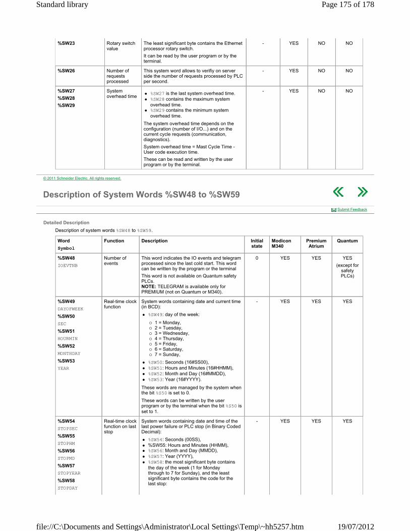
%SW23 Rotary switch value
The least significant byte contains the Ethernet processor rotary switch.
It can be read by the user program or by the terminal.
- YES NO NO
%SW26 Number of requests processed
This system word allows to verifiy on server side the number of requests processed by PLC per second.
- YES NO NO
%SW27
%SW28
%SW29
System overhead time
%SW27 is the last system overhead time. %SW28 contains the maximum system
overhead time. %SW29 contains the minimum system
overhead time.
The system overhead time depends on the configuration (number of I/O...) and on the current cycle requests (communication, diagnostics).
System overhead time = Mast Cycle Time - User code execution time.
These can be read and written by the user program or by the terminal.
- YES NO NO
© 2011 Schneider Electric. All rights reserved.
Description of System Words %SW48 to %SW59
Detailed Description
Description of system words %SW48 to %SW59.
Submit Feedback
Word
Symbol
Function Description Initial state
Modicon M340
Premium Atrium
Quantum
%SW48
IOEVTNB
Number of events
This word indicates the IO events and telegram processed since the last cold start. This word can be written by the program or the terminal
This word is not available on Quantum safety PLCs. NOTE: TELEGRAM is available only for PREMIUM (not on Quantum or M340).
0 YES YES YES
(except for safety PLCs)
%SW49
DAYOFWEEK
%SW50
SEC
%SW51
HOURMIN
%SW52
MONTHDAY
%SW53
YEAR
Real-time clock function
System words containing date and current time (in BCD):
%SW49: day of the week:
1 = Monday, 2 = Tuesday, 3 = Wednesday, 4 = Thursday, 5 = Friday, 6 = Saturday, 7 = Sunday,
%SW50: Seconds (16#SS00), %SW51: Hours and Minutes (16#HHMM), %SW52: Month and Day (16#MMDD), %SW53: Year (16#YYYY).
These words are managed by the system when the bit %S50 is set to 0.
These words can be written by the user program or by the terminal when the bit %S50 is set to 1.
- YES YES YES
%SW54
STOPSEC
%SW55
STOPHM
%SW56
STOPMD
%SW57
STOPYEAR
%SW58
STOPDAY
Real-time clock function on last stop
System words containing date and time of the last power failure or PLC stop (in Binary Coded Decimal):
%SW54: Seconds (00SS), %SW55: Hours and Minutes (HHMM), %SW56: Month and Day (MMDD), %SW57: Year (YYYY), %SW58: the most significant byte contains
the day of the week (1 for Monday through to 7 for Sunday), and the least significant byte contains the code for the last stop:
- YES YES YES
Page 175 of 178Standard library
19/07/2012file://C:\Documents and Settings\Administrator\Local Settings\Temp\~hh5257.htm
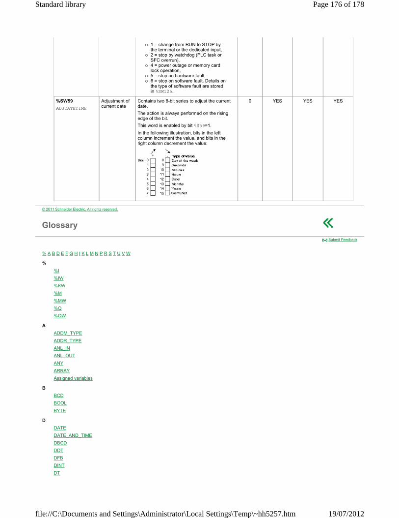
1 = change from RUN to STOP by the terminal or the dedicated input,
2 = stop by watchdog (PLC task or SFC overrun),
4 = power outage or memory card lock operation,
5 = stop on hardware fault, 6 = stop on software fault. Details on
the type of software fault are stored in %SW125.
%SW59
ADJDATETIME
Adjustment of current date
Contains two 8-bit series to adjust the current date.
The action is always performed on the rising edge of the bit.
This word is enabled by bit %S59=1.
In the following illustration, bits in the left column increment the value, and bits in the right column decrement the value:
0 YES YES YES
© 2011 Schneider Electric. All rights reserved.
Glossary
% A B D E F G H I K L M N P R S T U V W
%
%I
%IW
%KW
%M
%MW
%Q
%QW
A
ADDM_TYPE
ADDR_TYPE
ANL_IN
ANL_OUT
ANY
ARRAY
Assigned variables
B
BCD
BOOL
BYTE
D
DATE
DATE_AND_TIME
DBCD
DDT
DFB
DINT
DT
Submit Feedback
Page 176 of 178Standard library
19/07/2012file://C:\Documents and Settings\Administrator\Local Settings\Temp\~hh5257.htm

DWORD
E
EBOOL
EF
EFB
Elementary function
EN
ENO
F
FBD
FFB
FTP
Function
Function Block Diagram
G
Global Data
GRAY
H
HTTP
I
I/O scanning
IEC 61131-3
IL
INF
INT
IODDT
K
Keyword
L
LD
Literal value in base 10
Literal value in base 16
Literal value in base 2
Literal value in base 8
Literal value of a real
Literal value of a real with an exponent
Literal value of an integer
Literal value of time
M
Multitoken
N
Naming conventions (identifier)
NAN
Network
P
Peer cop
Procedure
R
REAL
S
SFC
SIL
Single token
SNMP
ST
Page 177 of 178Standard library
19/07/2012file://C:\Documents and Settings\Administrator\Local Settings\Temp\~hh5257.htm

STRING
T
TIME
TIME_OF_DAY
TOD
Token
TOPO_ADDR_TYPE
U
UDINT
UDP
UINT
Unassigned variables
V
Variable
W
WORD
© 2011 Schneider Electric. All rights reserved.
Page 178 of 178Standard library
19/07/2012file://C:\Documents and Settings\Administrator\Local Settings\Temp\~hh5257.htm