universal keypad user guide - leroy-somer€¦ · compatibility (emc) ... product universal keypad...
TRANSCRIPT

www.controltechniques.com
EF
User Guide
Universal Keypad
Part Number: 0400-0040Issue Number: 5

Safety InformationThe Control Techniques Universal Keypad is intended only for use as an accessory for Control Techniques variable speed drives. Any other attempted use invalidates the warranty and may be hazardous.The variable speed drives with which this keypad is used contain high power, high voltage parts, which can cause severe electric shock and burns and could be lethal. Refer to the drive installation guide before working on the drive system.Close attention is required to the drive system design to avoid safety hazards either in normal operation or in the case of faults. To ensure mechanical safety, additional safety devices such as electro-mechanical interlocks may be required. The keypad must not be used in a safety-critical application without additional high-integrity protection against hazards arising from a malfunction. In any application where a malfunction could cause damage, loss or injury a risk assessment must be carried out and, where necessary, measures taken to reduce the risk.System design, installation, commissioning and maintenance must be carried out by personnel who have the necessary training and experience, and they must pay close attention to this safety information and the contents of the installation guide.
Copyright © 28 November 2001 Control Techniques Drives LtdIssue Code: 5Firmware: 01.05.00

Contents
1 Declaration of Conformity 1
2 Introduction 22.1 Overview 22.2 Front Panel Layout 22.3 Technical Specifications 32.4 Compatibility 4
3 Installation 53.1 Power Supply 53.2 Rear panel layout and interconnections 53.3 Serial Communications 73.4 Connecting to a Drive 7
4 Keypad Operations 94.1 Basic Operation 94.2 Keypad Security features 94.3 Run, Stop/Reset and Direction buttons 104.4 Programmable function keys 114.5 Human-machine interface lines 124.6 Unidrive AutoStart with the Keypad 164.7 Notification of Drive Trips 184.8 Auto-Restart 18
Universal Keypad User GuideIssue Number: 5 www.controltechniques.com

5 Local Menu 99 195.1 #99.00 Save/Restore Local parameters 195.2 #99.01 Destination Node Address 195.3 #99.02 Drive Type (read-only) 195.4 #99.03 Keypad Address 195.5 #99.04 Keypad Baud Rate 205.6 #99.05 Control Keys (Run, Stop/Reset and Direction) 205.7 #99.06 Direction key 205.8 #99.09 HMI Display #1 Source Address 205.9 #99.10 HMI Display #1 Source Parameter 205.10 #99.11 HMI Display #1 Scale factor 205.11 #99.12 HMI Display #1 Offset 205.12 #99.13 HMI Display #1 Display String 215.13 #99.14 HMI Display #1 Numeric Value Location 215.14 #99.15 HMI Display #1 Numeric Value Format 215.15 #99.16 HMI Display #2 Source Address 215.16 #99.17 HMI Display #2 Source Parameter 215.17 #99.18 HMI Display #2 Scale factor 215.18 #99.19 HMI Display #2 Offset 225.19 #99.20 HMI Display #2 Display String 225.20 #99.21 HMI Display #2 Numeric Value Location 225.21 #99.22 HMI Display #2 Numeric Value Format 225.22 #99.23 F1 Key Assignment 225.23 #99.24 F1 Destination Address 225.24 #99.25 F1 Destination Menu / Parameter 235.25 #99.26 F1 Destination Value 1 235.26 #99.27 F1 Destination Value 2 235.27 #99.28 F2 Key Assignment 235.28 #99.29 F2 Destination Address 235.29 #99.30 F2 Destination Menu / Parameter 235.30 #99.31 F2 Destination Value 1 235.31 #99.32 F2 Destination Value 2 235.32 #99.33 F3 Key Assignment 245.33 #99.34 F3 Destination Address 245.34 #99.35 F3 Destination Menu / Parameter 245.35 #99.36 F3 Destination Value 1 245.36 #99.37 F3 Destination Value 2 245.37 #99.40 Software version 245.38 #99.41 HMI #2 Increment Value 245.39 #99.42 HMI #2 Increment Upper Limit 255.40 #99.43 HMI #2 Decrement Lower Limit 255.41 #99.44 Password 255.42 #99.45 Power-on Display Parameter 255.43 #99.46 HMI2 Alternate Increment Value 255.44 #99.47 Auto-Restart Enable 25
Universal Keypad User Guidewww.controltechniques.com Issue Number: 5

6 Keypad Dimensions 266.1 Front and Side view dimensions 266.2 Rear Panel and Aperture dimensions 27
7 UL Listing Information 28
Universal Keypad User GuideIssue Number: 5 www.controltechniques.com

1 Universal Keypad User Guidewww.controltechniques.com Issue Number: 5
1 Declaration of ConformityControl Techniques Plc, The Gro, Newtown, Powys, UK. SY16 3BE
The Universal Keypad has been designed and manufactured in accordance with the following European harmonised, national and international standards:
This product complies with the Low Voltage Directive 73/23/EEC, the Electromagnetic Compatibility (EMC) Directive 89/336/EEC and the CE Marking Directive 93/68/EEC.
Compliance with safety and EMC regulations depends upon installing and configuring the keypad correctly. The assembler is responsible for ensuring that the end product or system complies with all the relevant laws in the country where it is to be used. Refer to the User Guide. An EMC Data Sheet is also available giving detailed EMC information
Product Universal KeypadControl Techniques Part No. 8550-0000
EN61010-1 Safety requirements for electrical equipment for measurement, control, and laboratory use - general requirements.
EN50081-2 Generic emission standard for the industrial environmentEN50082-2 Generic immunity standard for the industrial environment
EN61800-3 Adjustable speed electrical power drive systems - Part 3: EMC product standard including specific test methods.
W. Drury
Technical Director
Date: 2 July 1999.

2 IntroductionMany applications consist of a small number of Drives mounted inside a cubicle or cabinet. A front panel mounted Universal Keypad will allow plant maintenance and commissioning.
2.1 OverviewThe Universal Keypad is a display and keyboard that communicates to the Unidrive, VTC, GP, Commander SE and Mentor II range of Drives using standard EIA-RS485 serial communications, with the CT-ANSI protocol.The keypad can access any Drive connected to the EIA-RS485 network and scroll through the parameter set providing native language descriptions.
The Unidrive must be fitted with a basic serial communications option (UD71) or applications module (UD70).The onboard two-line LCD display shows the menu number, parameter number and value on the top line and the 16-character parameter description on the bottom line. After 10 seconds of inactivity, two custom Human-machine Interface lines may be displayed. These HMI lines are programmed to read a parameter on any drive, apply a scale and offset and then display this data with descriptive text.The keypad is intended to be used in the following modes:
• Hand-held, for programming drives, including down-loading stored parameter sets
• Panel mounted, for service access to the parameters of one or more drives• Panel-mounted, for operation of plant
2.2 Front Panel LayoutThe front panel design was purposely styled to match the Unidrive family of products. Eight of the eleven membrane buttons have exactly the same function as the Unidrive's front panel keypad. These keys include the colored run, stop/reset and direction buttons, the arrow keys and the modify button. The three buttons labeled F1, F2 and F3 directly below the 2-line LCD display are the macro keys. These keys may be programmed by the user to send one or two stored values to any parameter on any drive that is on the EIA-RS485 network.
NOTE
Universal Keypad User Guide 2Issue Number: 5 www.controltechniques.com

Figure 2-1 Universal Keypad Front Panel Layout
2.3 Technical Specifications
9901 11destination addr
F1 F2 F3
M
Specification Value
EIA-RS485: 2-wire or EIA-RS485 4-wire interconnection
Supply voltage: 24V DC ±20%Rated current: 150mA
Maximum current:
200mA when supplied from a Control Techniques drive. When used with a separate DC supply use a fast-acting 250mA fuse rated at 24V DC with breaking capacity to suit supply.
Dimensions (W x H x D): 115mm x 188mm x 50mm (4.53" x 7.40" x 1.97")
Ambient Temperature: 0ºC to +50ºC
Altitude:The Universal Keypad is capable of operation at altitudes of 4000m above sea level.
Humidity:
Maximum relative humidity 80% for temperatures up to 31ºC decreasing linearly to 50% relative humidity at 40ºC
EMC:
Complies with EN50081-2 (emission), EN50082-2 (immunity) and IEC61800-3 (power drive systems)
3 Universal Keypad User Guidewww.controltechniques.com Issue Number: 5

2.4 CompatibilityThe following table shows a list of Drive versions that the Universal Keypad is compatible with:
*UD70 system file V2.7.6 and later. Earlier versions identify the drive as Unidrive open loop with menu 0 invalid.
Panel Mounting:Standard DIN 96mm X 96mm panel meter punch - 92mm x 92mm cutout
Environment:
Enclosure ingress protection when correctly assembled to a panel is IP65 for the outside (front) and IP30 for the inside (rear) surface.
Specification Value
Drive Drive option 4 wire 2 wire Drive firmware versionUnidrive UD71 or UD70 Yes Yes AllCommander SE None No Yes AllMentor II None Yes No All
Mentor II MD29 or MD29AN Yes Yes All
Unidrive VTC UD71 Yes Yes >= 3.0.0Unidrive VTC UD70* Yes Yes >= 3.0.0Commander GP UD71 Yes Yes >= 3.1.7
Universal Keypad User Guide 4Issue Number: 5 www.controltechniques.com

3 InstallationThe Universal Keypad is intended to be used in two ways:
• As a panel-mounted control unit for a drive or drive system. When used in this mode it may be used by plant operators and other staff with no specific skills or training.
• As a hand-held drive programming device. Since this requires access to the drive connections, it is intended for use in this mode only by trained and experienced technical personnel, who must carefully observe the safety precautions given in this guide and the drive installation guide.
For mounting and dimensions refer to section 6 Keypad Dimensions
3.1 Power SupplySupply voltage 24V DC nominal ±20%.The supply must either be current limited at 150mA nominal or else provided with a fast-acting 250mA fuse rated at 24V DC with a breaking capacity to suit supply. When used with the specified Control Techniques drive this protection is provided automaticallyThe power supply required by the Universal Keypad is 24 Volts ( ±20% ) at 150mA maximum. As Figure 3-1, Figure 3-2 and Figure 3-3 suggest, we recommend a good quality 4-conductor shielded, twisted pair cable for the communications channel. The rear panel housing has cable strain-relief built into the plastic molding.The Unidrive has 24 Volts, 200mA available on the signal connector, sufficient to power the Universal Keypad. Pin 22 is +24 Volts while pin 23 is the digital ground. A popular method is to use 6-conductor shielded cable and bring the power and ground leads out of the 9-pin connector's boot for attachment to the Unidrive's signal connector.The drive control terminals are separated from live circuits in the drive by basic insulation only. Accessible wiring between the keypad and drive must be insulated with at least one layer of insulation rated for the supply voltage in use.
This also applies to all other circuits fed from any DC supply used for this purpose. The same supply must not be used for operator accessible circuits or SELV circuits.
3.2 Rear panel layout and interconnectionsThe rear panel plastic molding is designed to push through a 92mm x 92mm aperture cut-out in the cabinet or cubicle. There are four tapped screw holes provided to secure the fitting. Removing the two screws securing the cable hatch cover can expose the rear terminal connector.Figure 3-1 shows the required power and signal interconnections for EIA-RS485 4-wire operation.Please note that the Commander SE drive does not support EIA-RS485 4-wire communications.
NOTE
5 Universal Keypad User Guidewww.controltechniques.com Issue Number: 5

Figure 3-1 EIA-RS485 4-wire Interconnection diagramPlease note that a Commander SE Drive only supports 2-wire communications whilst the Mentor Drive does not unless an MD29 card is fitted.
Figure 3-2 EIA-RS485 2-wire Interconnection diagramThe Universal Keypad works in both 4-wire and 2-wire mode with no user intervention or set-up required.
Universal KeypadRear Terminal Block
gnd Tx Tx Rx Rx gnd 24V
2
3
6
7
1
2
3
6
7
1
+24 Volts DCPower ground
Unidrive/GP/VTCConnector
9-Pin Female
MentorConnector
9-Pin Female
Universal KeypadRear Terminal Block
gnd Tx Tx Rx Rx gnd 24V
2
3
6
7
1
2
3
6
7
1
+24 Volts DCPower ground
Unidrive/GP/VTCConnector
9-Pin Female
MD29Connector
9-Pin Female
2
3
7
Commander SEConnector8-Pin RJ45
Universal Keypad User Guide 6Issue Number: 5 www.controltechniques.com

Figure 3-3 EIA-RS485 2-wire Commander SE interconnection with power connection.
3.3 Serial Communications3.3.1 Routing the serial communcations cable
A data communications cable should not run parallel to any power cables, especially ones that connect Drives to motors. If parallel runs are unavoidable, ensure a minimum spacing of 300mm (1 foot) between the communications cable and the power cable.Cables crossing one another at right-angles are unlikely to give trouble.The maximum cable length for a EIA-RS485 link is 1200 meters (4000 feet).
3.3.2 Network limitationsThe host controller can operate up to thirty-two EIA-RS485 devices with the use of line repeaters. Each transmitter or receiver of Control Techniques devices loads the line by two unit-loads. Therefore in 2-wire mode, each Control Techniques device loads the line by four unit loads. This means that no more than a total of seven such devices can be connected in a single group, allowing up to four unit-loads for the line repeater. Up to 15 devices can be connected if 4-wire mode is used.
3.3.3 Terminating the cableWhen a multi-drop EIA-RS485 system is used, connect a 120W resistor between the two receive lines of the last unit* in the chain (i.e. the farthest away from the host). Care must be taken to ensure that other units in the system do not have the resistor already fitted. Excessive signal loss will occur if termination resistors are connected to units other than the last one.If the last unit is a Commander SE connect pin 1 to pin 8 (/TX/RX) to activate the termination.
3.4 Connecting to a DriveFor the Universal Keypad to operate, a connection must be established between the keypad and a drive. The Universal Keypad will communicate with all supported CT drives (see section 2.4 Compatibility ), the exception of Mentor II, without the need for any parameter alterations on the drive or keypad from the default values.
Universal KeypadRear Terminal Block
gnd Tx Tx Rx Rx gnd 24V
Commander SEConnector8-Pin RJ45(plan view)
5
2
43
1
678
NOTE
7 Universal Keypad User Guidewww.controltechniques.com Issue Number: 5

After wiring the keypad connect to the EIA-RS485 port on the drive and applying power:Select the baud rate parameter (#99.04) and change to the correct baud rate for the drive.
• Select the drive address parameter (#99.01) and change to the appropriate value (exiting Modify mode will execute a 'reconnection').
• When the Universal Keypad has established communications with the drive a "RS485 Init OK" message is displayed briefly on the bottom LCD display line and the keypad jumps to the specified power-up parameter (defined in parameter #99.45).
The table below shows the Node communication parameters:
Figure 3-4 Selecting a Drive AddressYou can scroll at any time to local parameter #99.01 to change the destination drive address. There is a useful shortcut wherein pressing the LEFT and RIGHT ARROW buttons simultaneously will jump directly to local parameter #99.01.There are some limitations on drive addresses: no drive addresses less than 11 are permitted and you should avoid drive addresses in which the least significant digit is zero (e.g. 20, 30, 40, etc.). If the entered drive address does not exist, a "Comm Failure" message will be displayed briefly and you will be locked into local menu 99 until a valid drive is selected.
Node Baud Rate Parameter
RS485 Address Parameter
RS485 Mode Parameter
RS485 Mode Value
Universal Keypad #99.04 #99.01 N/A N/A
Unidrive, VTC, GP #0.36 (#11.25) #0.37 (#11.23) #0.32 (#11.24) =1 (4 wire)=0 (2 wire)
Commander SE #0.42 (#11.25) #0.43 (#11.23) #0.41 (#11.24) =0 (2 wire)Mentor II #11.12 #11.11 #11.13 =1 (4wire)
UD70 #17.07 #17.05 #17.06 =1 (4wire)=5 (2 wire)
MD29 #14.03 #14.01 #14.02 =1 (4wire)=5 (2 wire)
VALUE (drive address)MENU - PARAMETER
DESCRIPTION9901 11destination addr
Universal Keypad User Guide 8Issue Number: 5 www.controltechniques.com
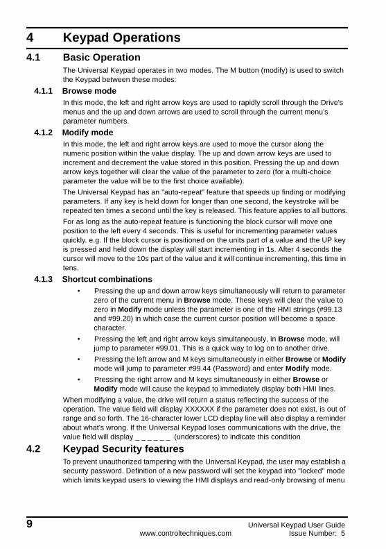
4 Keypad Operations4.1 Basic Operation
The Universal Keypad operates in two modes. The M button (modify) is used to switch the Keypad between these modes:
4.1.1 Browse modeIn this mode, the left and right arrow keys are used to rapidly scroll through the Drive's menus and the up and down arrows are used to scroll through the current menu's parameter numbers.
4.1.2 Modify modeIn this mode, the left and right arrow keys are used to move the cursor along the numeric position within the value display. The up and down arrow keys are used to increment and decrement the value stored in this position. Pressing the up and down arrow keys together will clear the value of the parameter to zero (for a multi-choice parameter the value will be to the first choice available).The Universal Keypad has an "auto-repeat" feature that speeds up finding or modifying parameters. If any key is held down for longer than one second, the keystroke will be repeated ten times a second until the key is released. This feature applies to all buttons.For as long as the auto-repeat feature is functioning the block cursor will move one position to the left every 4 seconds. This is useful for incrementing parameter values quickly. e.g. If the block cursor is positioned on the units part of a value and the UP key is pressed and held down the display will start incrementing in 1s. After 4 seconds the cursor will move to the 10s part of the value and it will continue incrementing, this time in tens.
4.1.3 Shortcut combinations• Pressing the up and down arrow keys simultaneously will return to parameter
zero of the current menu in Browse mode. These keys will clear the value to zero in Modify mode unless the parameter is one of the HMI strings (#99.13 and #99.20) in which case the current cursor position will become a space character.
• Pressing the left and right arrow keys simultaneously, in Browse mode, will jump to parameter #99.01. This is a quick way to log on to another drive.
• Pressing the left arrow and M keys simultaneously in either Browse or Modify mode will jump to parameter #99.44 (Password) and enter Modify mode.
• Pressing the right arrow and M keys simultaneously in either Browse or Modify mode will cause the keypad to immediately display both HMI lines.
When modifying a value, the drive will return a status reflecting the success of the operation. The value field will display XXXXXX if the parameter does not exist, is out of range and so forth. The 16-character lower LCD display line will also display a reminder about what's wrong. If the Universal Keypad loses communications with the drive, the value field will display _ _ _ _ _ _ (underscores) to indicate this condition
4.2 Keypad Security featuresTo prevent unauthorized tampering with the Universal Keypad, the user may establish a security password. Definition of a new password will set the keypad into "locked" mode which limits keypad users to viewing the HMI displays and read-only browsing of menu
9 Universal Keypad User Guidewww.controltechniques.com Issue Number: 5

zero, or in the case of the Mentor, all parameters. To return the keypad to "unlocked" mode, giving full access to all parameters, the user must re-enter the previously defined password.
4.2.1 Enabling/Disabling security• Access parameter #99.44 (pressing left and right arrows together will take you
straight to the parameter)• Enter your numeric password (zero is not a valid password)• Press the M (modify) button.• If the keypad was unlocked it will jump to menu 00 and briefly display a
"Keypad Locked" message. You will be able to browse parameters but not alter any values. Security is now enabled.
• If the keypad was locked and the password was correct it will jump to parameter #99.01 and briefly display a "Keypad Unlocked" message. You may now view any parameter and modify it's value if it is a read-write parameter. Security is now disabled. If the password was incorrect the keypad jumps to menu 00, briefly displays "Invalid Password" and remains Locked.
The Universal Keypad is shipped with the password set to 0 and the operational mode is "unlocked", thus giving full access to all parameters.Any changes made to the password and operational mode are automatically stored in the onboard non-volatile memory. If the power is temporarily interrupted, the password and operational mode will be restored when the keypad re-boots. If you forget the saved password, contact your Supplier.
4.3 Run, Stop/Reset and Direction buttonsThe Run, Stop/Reset and Direction buttons are designed to emulate the Unidrive onboard keypad. To implement this function correctly, the Control keys (#99.05) parameter in the keypad will need to be set to Enabled, in conjunction with the following settings:
The STOP button has 3 purposes:• If the Drive is tripped, the STOP button will first stop the Drive then RESET it.• If the Drive is running, the STOP button will stop the Drive.• If the Drive is stopped, the STOP button will RESET the Drive.
For those drives that support the virtual Drive Key Control parameter, simulating the STOP button works fine for stopping and resetting the drive. In all other cases, the "user trip" parameters are used to reset the drive (parameters #10.38 on the Unidrive and Commander SE and #10.35 on the Mentor).It is possible to disable the Direction button by setting parameter #99.06 in the keypad to 0 (Disabled). This will mean that if the drive is running (forward or reverse), pressing the direction button will have no effect.
Drive Enable link Parameter Parameter valueUnidrive UD71VTC UD71GP UD71
Terminal 30 to 31#6.04#1.14#6.13
=3 (PLC)=4 (Keypad)=1 (enable forward/reverse)
Unidrive UD70VTC UD70 Terminal 30 to 31
#6.04#1.14
Menu 8 destinations
=3 (PLC)=Any reference except keypad (4)=Any parameter other than #6.30 and #6.32
Commander SE Terminal 7 to 9 #0.05 =Any reference except keypadMentor II Terminals 21 & 21 to 40 #8.21 =1 (disable normal logic functions)
NOTE
Universal Keypad User Guide 10Issue Number: 5 www.controltechniques.com

4.4 Programmable function keysThe Universal Keypad has three Function Keys, labelled F1, F2 and F3. Each of these keys can be programmed by the user to send pre-determined values to any parameter on any attached drive. To do this, just five parameters in local menu 99 must be set up for each key.For example, to set up the F1 key to send a one followed by a zero to drive 15's sequencing bit (#6.30), set parameters #99.23 through #99.27 as shown in the table below (parameters shown in italics are for descriptive purposes and do not require setting up for this example to work):
Hint: The above example allows only 2 values to be written to the specified parameter. However, if you wish to write more values to a parameter (maximum of 6), you could set up the F2 and F3 function keys in the same way as F1Once the F1 parameters have been configured, the first time you push the F1 button, a "one" will be sent to drive 15, parameter #6.30. Being the sequencing bit zero, this should start the drive. The next time you push the F1 button, a "zero" will be sent which should stop the drive. This toggling action will operate ad infinitum. Unfortunately, there is no way to tell which value goes next.The value that the drive displays after the function key has been pressed depends on the value(s) that are being sent and the format of the drive parameter. The table below shows how to set up the function key values correctly:
F1 Button Set-up ParametersSet-up parameter Value Description#99.23 2 values F1 key assign#99.24 15 F1 destination address#99.25 630 F1 destination parameter#99.26 1 F1 value #1#99.27 0 F1 value #2
NOTE
Parameter format Keypad value Value indicated on drive
n.nn21521505
2.1521.500.05
n.n21521505
21.5215.00.5
nnnn21521505
21521505
11 Universal Keypad User Guidewww.controltechniques.com Issue Number: 5

4.5 Human-machine interface linesHuman-machine Interface lines, referred hereafter as HMI lines, are custom parametric displays that appear after 10 seconds of keypad inactivity or when the user presses the Right and M keys simultaneously. Figure 4-1 below shows a couple of representative HMI lines that might be used in a winder system. This is a dynamic display - the roll diameter and line speed are being measured and calculated about five times a second.
Figure 4-1 Typical HMI Line DisplayA HMI line consists of a drive parameter that is read, a scaling calculation, a custom string and some formatting. Seven local menu 99 parameters are required to set up a HMI line. The top HMI line is called HMI #2 while the bottom HMI line is called HMI #1.HMI lines start displaying after ten seconds of keypad inactivity. Striking certain editing keys (right and left arrows and the M button) cancels the HMI displays and reverts to the BROWSE or MODIFY mode you were in. The Function keys, UP and DOWN and the run, stop/reset and direction keys will not cancel the HMI display.Each HMI line displays a value based on a calculation:
Value = Parameter * Scale + OffsetThis is useful if you want to convert a drive parameter from one unit to another and display the new unit value on the keypad.
4.5.1 HMI Example 1Assume for the moment that the Roll diameter is defined by the following equation:Roll_diameter = #1.21 * 3.525 + 1.217Where: #1.21 = Drive 35, Menu 1, Parameter 21We'll need a display text string where we've left some room for the digits (digits start at position 11 in the text string and are formatted below as XXX.X):
Thus, we'd like to display the calculated value with a field width of 5 and one digit to the right of the decimal point.
Roll Diam: 256.4
HMI #1
Roll Diam: 256.4Line Speed:86.9
HMI #2
Char R o l l D i a m : 2 5 6 . 4Pos 0 1 2 3 4 5 6 7 8 9 10 11 12 13 14 15
Universal Keypad User Guide 12Issue Number: 5 www.controltechniques.com

Assuming the drive serial address is 11, the parameters required to setup the bottom HMI #1 line are shown in the table below. You will need to set parameter #99.09 to the appropriate address if this is not the case.
The only unusual feature in the HMI setup is the string entry. Whenever you scroll to parameter #99.13 (or parameter #99.20 for HMI line #2), the top LCD display line is erased and the entire 16-character string is presented. If you enter MODIFY mode, the LEFT and RIGHT ARROW buttons move the cursor to adjoining characters while the UP and DOWN ARROWS scroll the character at the cursor position through all the printable ASCII characters. Assuming the drive serial address is 11, the parameters required to setup the top HMI #2 line are shown in the table below. You will need to set parameter #99.16 to the appropriate address if this is not the case.
HMI Line #1 Setup Parameters (bottom line)Setup parameter Value Description
#99.09 11 HMI1 source addressNote: zero disables the HMI line
#99.10 118 HMI1 source menu/parametere.g. 118 means menu 01, parameter 18
#99.11 3865HMI1 scale (x1000 motif)e.g. 3865 means multiply value in #1.18 by 3.865
#99.12 16 HMI1 offset (x1000 motif)e.g. 16 means 0.016
#99.13 Line Speed: HMI1 text string#99.14 11 HMI1 value starting position (0 - 15)
#99.15 41 HMI1 value format (width.decimal places)e.g. width = 4, 1 decimal place
Note: set parameter #1.18 to 22.5 to get the result shown in Figure 4-1
HMI Line #2 Setup Parameters (top line)Setup parameter Value Description
#99.16 11 HMI2 source addressNote: zero disables the HMI line
#99.17 121 HMI2 source menu/parametere.g. 121 means menu 01, parameter 21
#99.18 3525HMI2 scale (x1000 motif)e.g. 3525 means multiply value in #1.21 by 3.525
#99.19 1217 HMI2 offset (x1000 motif)e.g. 1217 means 1.217
#99.20 Roll Diam: HMI2 text string#99.21 11 HMI2 value starting position (0 - 15)
#99.22 51 HMI2 value format (width.decimal places)e.g. width = 5, 1 decimal place
Note: set parameter #1.21 to 72.4 to get the result shown in Figure 4-1
13 Universal Keypad User Guidewww.controltechniques.com Issue Number: 5

4.5.2 HMI Example 2Assume you want to display the motor speed from a drive. To get a true reflection of the speed you would need to set the parameters shown ion the table below. If the drive serial address is not 11 then set parameter #99.09 appropriately.
Setting the HMI scale (#99.11) to 1000 and HMI offset (#99.12) to zero will ensure that the value of parameter #5.04 in the drive is the value that will be displayed on the keypad. If you enter a value of zero into #99.11 the value displayed will be the same as the value specified in #99.12.Parameters #99.13 and #99.20 can contain any character from the following character set:
The display scrolls through the characters in the order shown above.Pressing the UP and DOWN keys together while in Modify mode in parameters #99.13 and #99.20 will set the character at the current cursor position to a space, thus giving the user a quick way to clear character positions in the HMI display.
HMI Line #1 Setup Parameters (bottom line)Setup parameter Value Description
#99.09 11 HMI1 source addressNote: zero disables the HMI line
#99.10 504 HMI1 source menu/parametere.g. 504 means menu 05, parameter 04
#99.11 1000 HMI1 scale (x1000 motif)e.g. 1000 means multiply value in #5.04 by 1
#99.12 0 HMI1 offset (x1000 motif)e.g. 0 means no offset
#99.13 Motor Spd: HMI1 text string#99.14 11 HMI1 value starting position (0 - 15)
#99.15 50 HMI1 value format (width.decimal places)e.g. width = 5, 0 decimal place
Dec Char Dec Char Dec Char Dec Dec Dec32 [space] 48 0 64 @ 80 P 96 ` 112 p33 ! 49 1 65 A 81 Q 97 a 113 q34 “ 50 2 66 B 82 R 98 b 114 r35 # 51 3 67 C 83 S 99 c 115 s36 $ 52 4 68 D 84 T 100 d 116 t37 % 53 5 69 E 85 U 101 e 117 u38 & 54 6 70 F 86 V 102 f 118 v39 ‘ 55 7 71 G 87 W 103 g 119 w40 ( 56 8 72 H 88 X 104 h 120 x41 ) 57 9 73 I 89 Y 105 i 121 y42 * 58 : 74 J 90 Z 106 j 122 z43 + 59 ; 75 K 91 [ 107 k 123 {44 , 60 < 76 L 92 \ 108 l 124 |45 - 61 = 77 M 93 ] 109 m 125 }46 . 62 > 78 N 94 ^ 110 n 126 ~47 / 63 ? 79 O 95 _ 111 o
NOTE
Universal Keypad User Guide 14Issue Number: 5 www.controltechniques.com
Setting the HMI value format field to zero will cancel the HMI numeric display but will leave the string on the LCD line. This is a handy way to create a label for the function keys (use HMI1 to do this). Setting the HMI source address parameter to zero will cancel the entire HMI line.
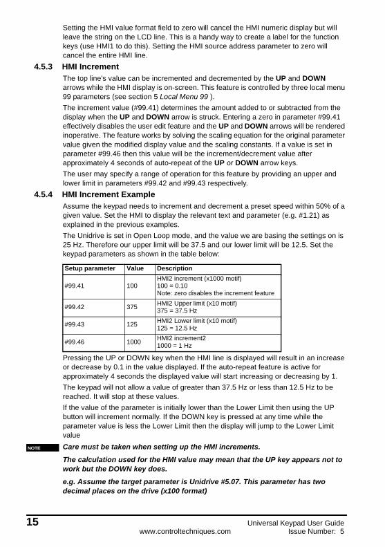
4.5.3 HMI IncrementThe top line's value can be incremented and decremented by the UP and DOWN arrows while the HMI display is on-screen. This feature is controlled by three local menu 99 parameters (see section 5 Local Menu 99 ).The increment value (#99.41) determines the amount added to or subtracted from the display when the UP and DOWN arrow is struck. Entering a zero in parameter #99.41 effectively disables the user edit feature and the UP and DOWN arrows will be rendered inoperative. The feature works by solving the scaling equation for the original parameter value given the modified display value and the scaling constants. If a value is set in parameter #99.46 then this value will be the increment/decrement value after approximately 4 seconds of auto-repeat of the UP or DOWN arrow keys.The user may specify a range of operation for this feature by providing an upper and lower limit in parameters #99.42 and #99.43 respectively.
4.5.4 HMI Increment ExampleAssume the keypad needs to increment and decrement a preset speed within 50% of a given value. Set the HMI to display the relevant text and parameter (e.g. #1.21) as explained in the previous examples.The Unidrive is set in Open Loop mode, and the value we are basing the settings on is 25 Hz. Therefore our upper limit will be 37.5 and our lower limit will be 12.5. Set the keypad parameters as shown in the table below:
Pressing the UP or DOWN key when the HMI line is displayed will result in an increase or decrease by 0.1 in the value displayed. If the auto-repeat feature is active for approximately 4 seconds the displayed value will start increasing or decreasing by 1.The keypad will not allow a value of greater than 37.5 Hz or less than 12.5 Hz to be reached. It will stop at these values.If the value of the parameter is initially lower than the Lower Limit then using the UP button will increment normally. If the DOWN key is pressed at any time while the parameter value is less the Lower Limit then the display will jump to the Lower Limit valueCare must be taken when setting up the HMI increments.The calculation used for the HMI value may mean that the UP key appears not to work but the DOWN key does.e.g. Assume the target parameter is Unidrive #5.07. This parameter has two decimal places on the drive (x100 format)
Setup parameter Value Description
#99.41 100HMI2 increment (x1000 motif)100 = 0.10Note: zero disables the increment feature
#99.42 375 HMI2 Upper limit (x10 motif)375 = 37.5 Hz
#99.43 125 HMI2 Lower limit (x10 motif)125 = 12.5 Hz
#99.46 1000 HMI2 increment21000 = 1 Hz
NOTE
15 Universal Keypad User Guidewww.controltechniques.com Issue Number: 5

#5.07 = increment - offset = .005 - 0 = 0.005
scale 1.0Assuming a value in the drive of 1.00, the keypad will display 1.00 also.
Pressing the DOWN key will cause 0.005 to be subtracted from the value in the keypad giving 0.995. This is then sent to the drive. Because #5.07 has only 2 decimal places the value is truncated (0.99) and read back from the drive so both drive and keypad display 0.99.
Pressing the UP key will cause 0.005 to be added to the value in the keypad giving 1.005. This is then sent to the drive. Because #5.07 has only 2 decimal places the value is truncated (1.00) and read back from the drive so both drive and keypad display 1.00 giving the impression that nothing has happened.Adhere to the following rule and you should not encounter any problems:
increment - offset = value
Scalex1 parameters (no decimal places) value must be >= 1
x10 parameters (1 decimal places) value must be >= 0.1
x100 parameters (2 decimal places) value must be >= 0.01x1000 parameters (3 decimal places) value must be >= 0.001
4.6 Unidrive AutoStart with the KeypadThe following set-up and associated UD70 DPL code, allow the Universal Keypad and the Unidrive to be used in Power Down Dependant Auto Start mode. The Universal Keypad is also used to control the speed of the Unidrive and also displays frequency reference applied and the actual speed of the motor.This set-up requires a UD70 large option module to be fitted to the Unidrive with the following DPL program loaded.Initial {
#6.30 = #20.21 // drive running
#6.32 = #20.22 // direction
}
Background {
top:
#20.21 = #6.30
#20.22 = #6.32
goto top: // main background loop
}
Universal Keypad User Guide 16Issue Number: 5 www.controltechniques.com
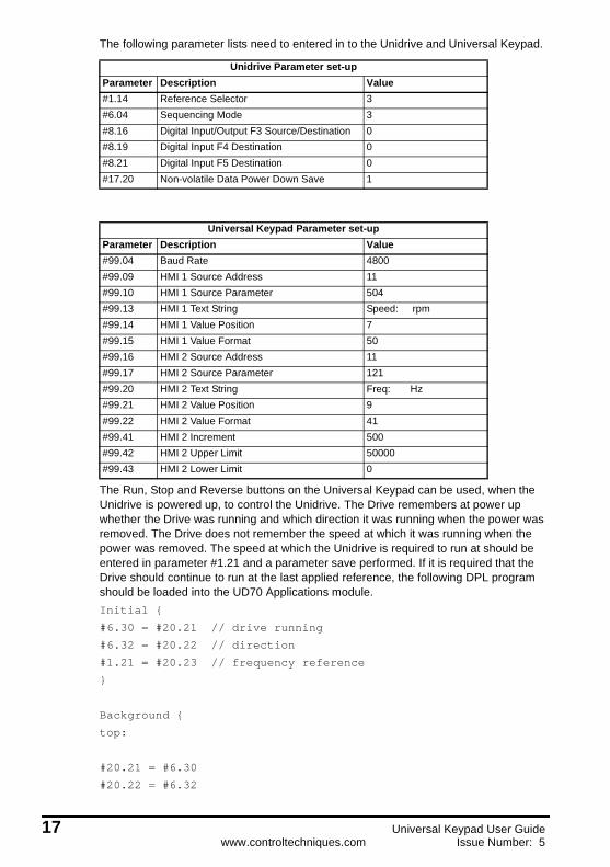
The following parameter lists need to entered in to the Unidrive and Universal Keypad.
The Run, Stop and Reverse buttons on the Universal Keypad can be used, when the Unidrive is powered up, to control the Unidrive. The Drive remembers at power up whether the Drive was running and which direction it was running when the power was removed. The Drive does not remember the speed at which it was running when the power was removed. The speed at which the Unidrive is required to run at should be entered in parameter #1.21 and a parameter save performed. If it is required that the Drive should continue to run at the last applied reference, the following DPL program should be loaded into the UD70 Applications module.Initial {
#6.30 = #20.21 // drive running
#6.32 = #20.22 // direction
#1.21 = #20.23 // frequency reference
}
Background {
top:
#20.21 = #6.30
#20.22 = #6.32
Unidrive Parameter set-upParameter Description Value#1.14 Reference Selector 3#6.04 Sequencing Mode 3#8.16 Digital Input/Output F3 Source/Destination 0#8.19 Digital Input F4 Destination 0#8.21 Digital Input F5 Destination 0#17.20 Non-volatile Data Power Down Save 1
Universal Keypad Parameter set-upParameter Description Value#99.04 Baud Rate 4800#99.09 HMI 1 Source Address 11#99.10 HMI 1 Source Parameter 504#99.13 HMI 1 Text String Speed: rpm#99.14 HMI 1 Value Position 7#99.15 HMI 1 Value Format 50#99.16 HMI 2 Source Address 11#99.17 HMI 2 Source Parameter 121#99.20 HMI 2 Text String Freq: Hz#99.21 HMI 2 Value Position 9#99.22 HMI 2 Value Format 41#99.41 HMI 2 Increment 500#99.42 HMI 2 Upper Limit 50000#99.43 HMI 2 Lower Limit 0
17 Universal Keypad User Guidewww.controltechniques.com Issue Number: 5

#20.23 = #1.21
goto top: // main background loop
}
The speed can be adjusted by the up and down arrow keys on the Universal Keypad, but only when the HMI text strings are present on the display. The text strings are displayed after approximately 10 seconds when no buttons have been pressed on the Universal Keypad.
Unlike using the UD71 Basic Serial Communications large option module, the drive will not trip SCL if RS485 communication is lost between the UD70 and the Universal Keypad.
4.7 Notification of Drive TripsThe Universal Keypad monitors the "drive healthy" parameter once a second. If the drive trips, the bottom LCD line displays "Drive Tripped" for approximately one second followed by a one second display of the nature of the trip. The display will then revert to showing the parameter and it's value as normal. The "Drive Tripped" text will display every two seconds on the bottom LCD line for as long as the drive is in the tripped state.The trip is cleared by hitting the Stop/Reset button.
4.8 Auto-RestartThe Universal Keypad provides a rudimentary Auto-Restart feature. If the auto-restart parameter #99.47 is set to a one, the Keypad will attempt to restart the drive if communications was interrupted or power was lost while the drive was running. It is assumed that the control keys are enabled (#99.05 = Enable) and the drive is configured to permit the Universal Keypad's RUN and STOP buttons to operate the drive. When the Universal Keypad commands the drive to start, this fact is remembered in the onboard non-volatile storage. If power is interrupted, the start command will be re-submitted when power is restored only if the Keypad had previously commanded the drive to start.
CAUTION
Universal Keypad User Guide 18Issue Number: 5 www.controltechniques.com

5 Local Menu 99The Universal Keypad has an onboard non-volatile memory that is used to save/restore the local set-up menu 99. This local menu works exactly like the drive menus except that no serial communications are involved in accessing this menu. When the keypad arrives from the factory, the local menu 99 will be set to standard factory defaults (4800 baud, drive 11, etc.). If you make changes to menu 99, you can save these changes in non-volatile memory so that these settings are automatically restored when you power up the Universal Keypad.
5.1 #99.00 Save/Restore Local parameters1000 = save Menu 99 in serial EEROM1244 = restore Menu 99 defaults1255 = restore Menu 99 from serial EEROM
Default: 0
Note: Activate the action by pressing the STOP/RESET button
5.2 #99.01 Destination Node Addressnn = EIA-RS485 serial address of the drive you wish to query (11..99)
Default: 11
Note: Using the short-cut of simultaneously pressing the LEFT and RIGHT arrow keys in BROWSE mode allows you to directly enter this parameterExiting modify mode in this parameter will execute a 'reconnection' to the drive.
5.3 #99.02 Drive Type (read-only)nn = drive model, operational mode and coprocessor
0 = No Drive 6 = Uni Cl UD70 12 = Mentor1 = Uni Open 7 = Uni Sv UD70 13 = Mentor MD292 = Uni Closed 8 = Uni Rg UD70 14 = Cmdr SE Mot13 = Uni Servo 9 = Uni VTC 15 = Cmdr SE Mot24 = Uni Regen 10 = Uni Vt UD705 = Uni Op UD7011 = UnidriveGP
5.4 #99.03 Keypad Addressnn = EIA-RS485 serial address of the keypad (11..99)
Default: 99
19 Universal Keypad User Guidewww.controltechniques.com Issue Number: 5

5.5 #99.04 Keypad Baud Rate0 = 4800, 1 = 9600, 2 = 19200, 3 = 38400
Default: 9600
5.6 #99.05 Control Keys (Run, Stop/Reset and Direction)0 = Disable, 1 = Enable
Default: Disable
5.7 #99.06 Direction key0 = Disable, 1 = Enable
Default: Enable
5.8 #99.09 HMI Display #1 Source Addressnnn = network address of desired parameter
Default: 0
Note: 11 .. 99 for RS485 systemsHint: zero suppresses this HMI line
5.9 #99.10 HMI Display #1 Source Parametermmpp = menu/parameter of the desired parameter for this display.(e.g. 1224 refers to menu 12, parameter 24)
Default: 121
5.10 #99.11 HMI Display #1 Scale factornnnnn = scale factor in x1000 motif(e.g. 24629 means 24.629)
Default: 1000
5.11 #99.12 HMI Display #1 Offsetnnnnn = offset in x1000 motif(e.g. 1206 means 1.206)
Default: 0
Universal Keypad User Guide 20Issue Number: 5 www.controltechniques.com

5.12 #99.13 HMI Display #1 Display StringTAPER = % (16 chars max)
Default: Roll Dia:
Note: Modifying this parameter brings up the new Label maker SystemThe LEFT and RIGHT arrows position the LCD cursor.The UP and DOWN arrows scroll through the alphabet.Leave some blank spaces to display the parameter value
5.13 #99.14 HMI Display #1 Numeric Value Locationnn = starting cursor position for numeric value (0 .. 15)
Default: 11
5.14 #99.15 HMI Display #1 Numeric Value Formatwd = width, decimal placesw = 0 .. 8 (field width); d = 0 .. 3 (# digits to right of decimal place)e.g. to display a value in the format 123.45 use the format specifier 62
Default: 41
5.15 #99.16 HMI Display #2 Source Addressnnn = network address of desired parameter
Default: 0
Note: 11 .. 99 for RS485 systemsHint: zero suppresses this HMI line
5.16 #99.17 HMI Display #2 Source Parametermmpp = menu/parameter of the desired parameter for this display.(e.g. 1224 refers to menu 12, parameter 24)
Default: 118
5.17 #99.18 HMI Display #2 Scale factornnnnn = scale factor in x1000 motif(e.g. 24629 means 24.629)
Default: 1000
21 Universal Keypad User Guidewww.controltechniques.com Issue Number: 5
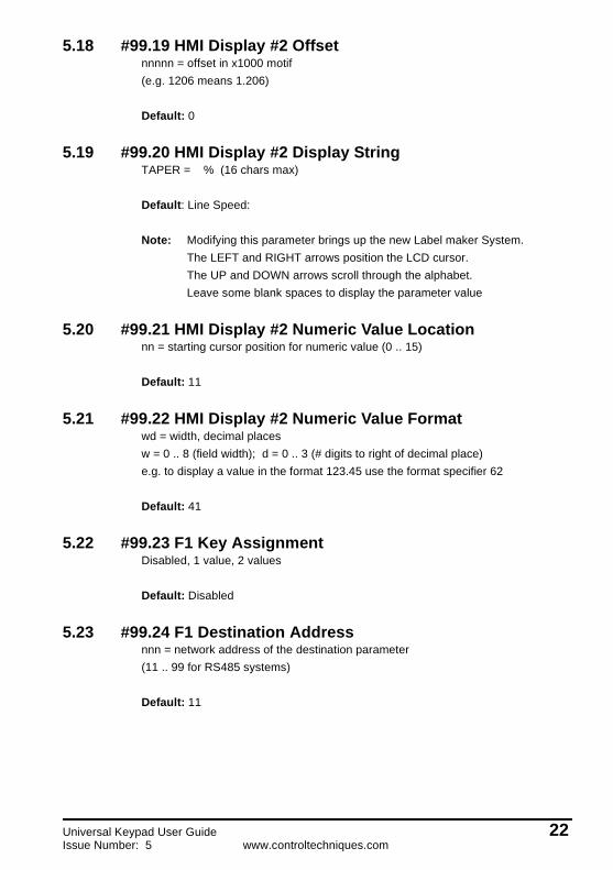
5.18 #99.19 HMI Display #2 Offsetnnnnn = offset in x1000 motif(e.g. 1206 means 1.206)
Default: 0
5.19 #99.20 HMI Display #2 Display StringTAPER = % (16 chars max)
Default: Line Speed:
Note: Modifying this parameter brings up the new Label maker System.The LEFT and RIGHT arrows position the LCD cursor.The UP and DOWN arrows scroll through the alphabet.Leave some blank spaces to display the parameter value
5.20 #99.21 HMI Display #2 Numeric Value Locationnn = starting cursor position for numeric value (0 .. 15)
Default: 11
5.21 #99.22 HMI Display #2 Numeric Value Formatwd = width, decimal placesw = 0 .. 8 (field width); d = 0 .. 3 (# digits to right of decimal place)e.g. to display a value in the format 123.45 use the format specifier 62
Default: 41
5.22 #99.23 F1 Key AssignmentDisabled, 1 value, 2 values
Default: Disabled
5.23 #99.24 F1 Destination Addressnnn = network address of the destination parameter(11 .. 99 for RS485 systems)
Default: 11
Universal Keypad User Guide 22Issue Number: 5 www.controltechniques.com
5.24 #99.25 F1 Destination Menu / Parametermmpp = menu / parameter of the destination parameter.(e.g. 1224 refers to menu 12, parameter 24)
Default: 0
5.25 #99.26 F1 Destination Value 1nnnnnn = value
Default: 0
5.26 #99.27 F1 Destination Value 2nnnnnn = value
Default: 1
5.27 #99.28 F2 Key AssignmentDisabled, 1 value, 2 values
Default: Disabled
5.28 #99.29 F2 Destination Addressnnn = network address of the destination parameter(11 .. 99 for RS485 systems)
Default: 11
5.29 #99.30 F2 Destination Menu / Parametermmpp = menu / parameter of the destination parameter.(e.g. 1224 refers to menu 12, parameter 24)
Default: 0
5.30 #99.31 F2 Destination Value 1nnnnnn = value
Default: 0
5.31 #99.32 F2 Destination Value 2nnnnnn = value
Default: 1
23 Universal Keypad User Guidewww.controltechniques.com Issue Number: 5

5.32 #99.33 F3 Key AssignmentDisabled, 1 value, 2 values
Default: Disabled
5.33 #99.34 F3 Destination Addressnnn = network address of the destination parameter(11 .. 99 for RS485 systems)
Default: 11
5.34 #99.35 F3 Destination Menu / Parametermmpp = menu / parameter of the destination parameter.(e.g. 1224 refers to menu 12, parameter 24)
Default: 0
5.35 #99.36 F3 Destination Value 1nnnnnn = value
Default: 0
5.36 #99.37 F3 Destination Value 2nnnnnn = value
Default: 1
5.37 #99.40 Software versionnnnnn = software revision number hard coded in the Keypad's EPROMe.g. 10105 = Software version 01.01.05
5.38 #99.41 HMI #2 Increment Valuennnnnn = increment value for HMI #2 display field (x1000 motif)e.g. 1500 = 1.5 added/subtracted from display each time UP ARROW or DOWN ARROW is struck
Default: 0
Note: entering a zero value disables this feature
Universal Keypad User Guide 24Issue Number: 5 www.controltechniques.com

5.39 #99.42 HMI #2 Increment Upper Limitnnnnnn = max value for HMI #2 display field (x10 motif)e.g. 800 = 80.0 (Increment button cannot exceed this)
Default: 999999
5.40 #99.43 HMI #2 Decrement Lower Limitnnnnnn = min value for HMI #2 display field (x10 motif)e.g. 500 = 50.0 (Decrement button cannot exceed this)
Default: -999999
5.41 #99.44 Passwordnnnnn = user-entered password (digits)
Default: 0
5.42 #99.45 Power-on Display Parametermmpp = parameter to be displayed after power-upe.g. 1224 refers to menu 12, parameter 24
Default: 10 (menu zero, parameter 10)
5.43 #99.46 HMI2 Alternate Increment Value
nnnnnn =second increment value for HMI #2 display field (x1000 motif)This value is used after ten seconds of auto-repeat. (e.g. 4500=4.5 added/subtracted from display)
Default: 0
Note: entering a zero value disables this feature
5.44 #99.47 Auto-Restart Enable
0 = disabled, 1 = enabled
Note: Keypad Control Keys must be enabled (#99.05 = enabled).The Keypad will resubmit the START command after the power-fail only if it previously commanded the drive to start.
Default: 0 (disabled)
25 Universal Keypad User Guidewww.controltechniques.com Issue Number: 5
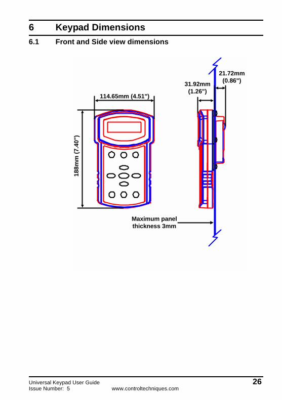
6 Keypad Dimensions6.1 Front and Side view dimensions
114.65mm (4.51")
188m
m (7
.40"
)31.92mm
(1.26")
21.72mm(0.86")
Maximum panelthickness 3mm
Universal Keypad User Guide 26Issue Number: 5 www.controltechniques.com

6.2 Rear Panel and Aperture dimensions
46mm(1.81")
46mm(1.81")
51.25mm(2.02")
51.25mm(2.02")
51.2
5mm
(2.0
2")
51.2
5mm
(2.0
2")
Aperture
46mm
(1.81")46m
m(1.81")
0 4.2mm(0.17")
60mm (2.36")
27 Universal Keypad User Guidewww.controltechniques.com Issue Number: 5

Universal Keypad User Guide 28Issue Number: 5 www.controltechniques.com
7 UL Listing InformationThese devices are for use in the secondary of a Class 2 circuit, or for use only with Drive Models as shown below when additionally fitted with a Listed Current limiting type fuse rated max 1A on the supply input to the device:
• Unidrive size 1,2,3,4 and 5 Drives• Mentor II Drives• Commander SE size 1 Drives
UL enclosure Type 1.