university of groningen modelling and analysis of human
TRANSCRIPT

University of Groningen
Modelling and analysis of human collaboration processes in organizationsStuit, Marco
IMPORTANT NOTE: You are advised to consult the publisher's version (publisher's PDF) if you wish to cite fromit. Please check the document version below.
Document VersionPublisher's PDF, also known as Version of record
Publication date:2011
Link to publication in University of Groningen/UMCG research database
Citation for published version (APA):Stuit, M. (2011). Modelling and analysis of human collaboration processes in organizations. University ofGroningen, SOM research school.
CopyrightOther than for strictly personal use, it is not permitted to download or to forward/distribute the text or part of it without the consent of theauthor(s) and/or copyright holder(s), unless the work is under an open content license (like Creative Commons).
The publication may also be distributed here under the terms of Article 25fa of the Dutch Copyright Act, indicated by the “Taverne” license.More information can be found on the University of Groningen website: https://www.rug.nl/library/open-access/self-archiving-pure/taverne-amendment.
Take-down policyIf you believe that this document breaches copyright please contact us providing details, and we will remove access to the work immediatelyand investigate your claim.
Downloaded from the University of Groningen/UMCG research database (Pure): http://www.rug.nl/research/portal. For technical reasons thenumber of authors shown on this cover page is limited to 10 maximum.
Download date: 03-04-2022

Chapter 2
Agent-oriented modelling and verification of human collaboration processes
This chapter is an edited version of the manuscript: Marco Stuit and Nick B. Szirbik. Towards agent-based modelling and verification of collaborative business processes: An approach centred on interactions and behaviours. International Journal of Cooperative Information Systems, 18(3/4), 2009.

Chapter 2
24
Abstract
his chapter presents an interaction-centric business process modelling language, named TALL, based on agent-oriented concepts. The language is both formal and graphical. Existing agent-oriented modelling languages,
developed in the multi-agent community, focus heavily on software implementation issues. This chapter argues that (networks of) organizations, which elect or envisage multi-agent systems for the support of human collaboration processes (HCPs), should start with a proper process-oriented understanding of the collaborative work practice of the agents in the business domain under consideration. The TALL modelling language introduces a novel diagram to represent the wide range of human interactions in a HCP as a hierarchy of role-based interactions in a tree structure. In the tree structure, human interactions have both composition and routing relations to each other. The behaviours owned by the agents playing the roles in the tree are specified in separate process diagrams. A HCP studied in the context of a case study at a Dutch gas transport company is used to illustrate the modelling language. Explicit (agent-oriented) process models can and should be verified using formal methods. In the business process management community, design-time verification of a process definition is considered vital to ensure the structural correctness and termination of a business process. The proposed modelling language is enhanced with a design-time verification method. The direction taken in this research is to combine the interaction tree and the associated agent behaviours into a verifiable hierarchical coloured Petri net to take advantage of its well-defined (execution) semantics and proven (computerized) verification techniques. The design-time verification method consists of three steps: (1) the translation of the TALL diagrams to a hierarchical coloured Petri net, (2) the identification of process design errors, and (3) the correction and rollback of process design errors to the TALL diagrams. The translation technique is implemented in a software tool that outputs the hierarchical coloured Petri net in a format that can be loaded in the widely used CPN Tools software package. Verification results are discussed for the case study models.
T

Agent-oriented modelling and verification of human collaboration processes
25
2.1. Introduction
Pervasive graphical process modelling languages like BPMN (White, 2004), WS-BPEL (OASIS, 2007), Petri nets (Desel, 2005), UML activity diagrams (Dumas & ter Hofstede, 2001; Eshuis, 2002), EPCs (Scheer, Thomas, & Adam, 2005), and IDEF0 (Mayer, Painter, & deWitte, 1992) create structured well-defined process models. In these languages, the collection of tasks or activities in the business process is ordered in a strict pre-defined execution sequence that is performed in an imperative way (Pesic & van der Aalst, 2006). Such languages are appropriate for modelling business processes that display complex activity or task flows but are less appropriate for modelling business processes that involve the interaction of a multitude of actors (Barjis, 2007; De Backer, Snoeck, Monsieur, Lemahieu, & Dedene, 2009; Hommes, 2004; Melão & Pidd, 2000; Ryu & Yücesan, 2007).
Nowadays, Information Technology (IT) systems that support human collaboration processes (HCPs), which usually run across internal (e.g. team, departmental) and external (e.g. organizational) boundaries are becoming popular to foster horizontal collaboration and information sharing. In HCPs, collaboration instead of task sequence determines the nature of the business activity. According to (Harrison-Broninski, 2005), collaborative activity simply does not match in any way the underlying “parallel flowchart” paradigm of current mainstream process notations and languages. Thus, novel modelling tools are required.
An increasing number of research efforts (Binder, Constantinescu, Faltings, Haller, & Türker, 2006; Buhler & Vidal, 2005; Ehrler, Fleurke, Purvis, & Savarimuthu, 2006; Verginadis & Mentzas, 2008; Yan, Maamar, & Shen, 2001) apply agents in the business process management domain by creating agent-oriented workflow management and business process management systems. These approaches offer more process flexibility, which is important for the application of business process support and automation in less structured application domains. There seems to be an opportunity for IT support by building software agents for support of (human) collaborative work practice (Partsakoulakis & Vouros, 2006). The agent paradigm promotes autonomous action and decision-making, which makes it relevant for modelling and implementing distributed business processes (Taveter & Wagner, 2002). However, most of these agent-oriented business process approaches are directed at the use of agents as part of the architecture and/or infrastructure associated with the system. Thus, the focus is on the use of agents as a technology rather than as a (business process) modelling framework.

Chapter 2
26
Well-known agent-oriented software engineering methodologies like MaSE (DeLoach, Wood, & Sparkman, 2001), Prometheus (Cheong & Winikoff, 2006; Padgham & Winikoff, 2003; Padgham & Winikoff, 2004), Tropos (Bresciani, Perini, Giorgini, Giunchiglia, & Mylopoulos, 2004), Gaia (Wooldridge, Jennings, & Kinny, 2000), and MESSAGE (Caire, et al., 2001; Caire, et al., 2002) support the agent system development process from analysis and design to implementation. Dedicated agent-based modelling languages are core components of these methodologies. Other agent-based modelling languages include, amongst others, AUML (Bauer, Müller, & Odell, 2001; Odell, Van Dyke Parunak, & Bauer, 2000), AORML (Wagner, 2003), AML (Cervenka, Trenanský, Calisti, & Greenwood, 2005; Cervenka, Trenanský, & Calisti, 2006; Trenanský & Cervenka, 2005), and OPM/MAS (Sturm, Dori, & Shehory, 2003). All these agent-based languages are information systems modelling techniques, and are not fully and easy applicable to business process design and analysis. In general, they are focused on system specification instead of business process specification.
As process-aware IT systems (Dumas, van der Aalst, & ter Hofstede, 2005) grow in scale and complexity (e.g. multi-agent systems), business process modelling becomes increasingly crucial to model and understand the business processes to be supported. Therefore, this chapter stresses that organizations that
elect or envisage agent technology for HCP support should start with a proper understanding of the work practice of the agents in the business domain under consideration.
This chapter consists of two main parts. The first part presents the TALL modelling language, a graphical and formal interaction-centric business process modelling language, inspired by the agent paradigm. The development of the language is motivated by the need for novel modelling tools for (agent-driven) HCPs. The main innovation of TALL is that it is a business process modelling language, based on agent-oriented concepts and notations. Thus, the language is more suited for business process modelling than the agent-based languages, which focus mainly on system specification. In the language, HCPs are addressed in two ways. On a high level, an interaction diagram is used to visualize inter-agent interactions in a tree layout. In the interaction diagram, a HCP is conceived as a structure of role-based interactions in which agents behave and coordinate their work. Individual agent behaviours are specified in process models, which are owned by the agents who are assigned to play the roles in the interaction diagram.

Agent-oriented modelling and verification of human collaboration processes
27
The logical step after a HCP has been modelled with TALL is to implement it in a multi-agent system for execution purposes. However, fundamental flaws in the agent behaviours should be identified before these are used for further design and/or implementation. For instance, to directly code the behaviours of software agents in a multi-agent system that supports the HCP. Design-time verification is concerned with determining whether a process model exhibits certain desirable structural properties before it is used for execution (Wynn, Verbeek, van der Aalst, ter Hofstede, & Edmond, 2009). Verification is essential in collaborative business settings (De Backer, Snoeck, Monsieur, Lemahieu, & Dedene, 2009; Ryu & Yücesan, 2007) where the design and run-time complexity of the process increases because agents perform their local behaviours autonomously when engaged in interactions.
The second part of this chapter is devoted to an execution-platform-independent design-time verification method. This method is focused on the structural correctness and compatibility of the agent behaviours that perform the interactions in a given HCP5. The direction taken in this research is to translate the TALL HCP (THCP) model (i.e. the combined interaction and behaviour diagrams) into a hierarchical Coloured Petri (CP) net to take advantage of its well-defined (execution) semantics and proven (computerized) verification techniques. The verification method is able to verify the structural composition of individual agent behaviours into the interactions that form a HCP. The user can experiment with a specific set-up of agent behaviours to check if they contain no design errors and inconsistencies, and send each other the required messages to complete the interactions. After correction, this results in a coordinated set-up of the agents that avoids deadlock and livelock situations6, which is a necessary and desirable property of agent systems (Nwana, Lee, & Jennings, 1996). The design-time verification method enhances the quality and reliability of the THCP model and the (future) multi-agent system that supports the HCP. After verification, the agent behaviours can be subject to further analysis, design, simulation, and/or implementation.
5 A HCP model is structurally correct if there exists, for each interaction in the HCP, at least one (collaborative) scenario that can successfully end through a specific set-up of agent behaviours. Section 2.4 discusses the design-time verification method in more detail. 6 Deadlock refers to a state of affairs in which further action between two or more agents is impossible. On the contrary, livelock refers to a scenario where agents continuously act (e.g. exchange tasks), but no progress is made (Nwana, Lee, & Jennings, 1996).

Chapter 2
28
The TALL modelling language and the supporting verification method are useful in the field of requirements engineering for multi-agent systems7. This chapter is not concerned with the question how TALL’s semantics can be implemented by an (existing) agent platform. Each platform may attach its own semantics to an input process specification or may not even have formal execution semantics to run process models. A TALL-focused evaluation of agent platforms is beyond the scope of this chapter.
The remainder of this chapter is structured as follows. Section 2.2 introduces a case study of a real-life HCP that is used throughout this chapter to illustrate the language and verification method. Next, Section 2.3 presents TALL. After, Section 2.4 introduces the proposed verification method. Section 2.5 describes the set of translation functions that translate the THCP model to a hierarchical CP net. Next, Section 2.6 describes formal verification of the hierarchical CP net and the correction of the THCP model based on the verification results. After, Section 2.7 provides a discussion. Section 2.8 presents related work. Finally, Section 2.9 gives conclusions and highlights future work.
2.2. Case Study
A case study of a real-life HCP at Gasunie Transport Services Inc. (GTS), concerned with the provision of gas transport services (from now on: the GTS process), is used to illustrate the TALL modelling language and the design-time verification method. GTS agreed to participate in a case study where the authors received access to company documentation and received permission to meet with process experts and participants. Thus, the primary form of data collection was desk study, and interviews8 with process experts and participants.
The liberalization of the gas market in The Netherlands on July 1, 2005 implied a strict separation between the trade and transport of natural gas. The national Dutch gas infrastructure company NV Nederlandse Gasunie was split into two autonomous companies, a gas transport company named Gasunie, and a purchasing and sales company for natural gas named GasTerra. The main activity of Gasunie is to manage, maintain, and adjust the gas transport system. The division GTS of Gasunie is responsible for the management, operation, and development of the
7 A single superior solution is not advocated with TALL. Existing agent-based languages and development paradigms can be used to describe different aspects of a multi-agent system in more detail or to finally build the software agents. 8 The interviews had the form of informal iterative consultations. Therefore, this chapter does not discuss in detail the interview process.

Agent-oriented modelling and verification of human collaboration processes
29
national gas transport grid on an economic basis. GTS provides gas transport services in order to promote a well-functioning liberalized gas market. Transport services are mainly requested by shippers, the largest customer group of GTS. A shipper is a company that uses the grid to transport gas. As soon as a shipper concludes a transport contract with GTS, it is regarded a supplier of gas to end-users (i.e. the actual users of gas like residential consumers, businesses, or industries).
The GTS process provides shippers with several gas transport-related services9. Service provisioning has become increasingly electronic in recent years. GTS uses a web-enabled ERP system to offer certain services to shippers. Still, several services have to be requested manually by fax or e-mail through an application form that is downloaded at the website of GTS. These services are called ‘offline’ services and are handled manually. Moreover, certain online services require considerable manual effort. The manual service requests require collaboration between the shipper and GTS, and between the (technical, legal, financial etc.) employees within GTS. Because of the complexity of the service request, the vast amount of data that needs to be verified, the specific requirements of certain shippers and the involvement of multiple departments, continuous human interaction is required.
The GTS process has been simplified to take into account a non-disclosure agreement but also for the purpose of explanation and illustration. Nevertheless, the key aspects of the process are still present. The case study focuses on a fragment of the GTS process that is concerned with a selection of transport services:
Booking of Entry/Exit Capacity: GTS uses an entry-exit system for the national gas transmission grid, in which the gas enters the grid at entry points and leaves the grid at exit points. Shippers can book both entry- and exit transport capacity;
Reduction of Contracted Capacity: A shipper can reduce the contracted capacity by 20% free of charge;
Shift of Capacity: A shift of capacity allows capacity that was booked for a particular exit point to be transferred to another exit point for a specified period.
9 For a description of all the transport services that can be booked by shippers, the website of GTS can be consulted: http://www.gastransportservices.nl/en/homepage.

Chapter 2
30
As part of the booking process for entry/exit capacity, GTS performs a technical capacity check a financial availability check. Most of the capacity checks can be executed by the ERP system since the requested capacity is simply compared with the available capacity. However, in certain areas of the transport grid, network points are clustered and influence each other. The complexity of the capacity check for such network points requires an employee of the back office (i.e. the capacity planner) to perform a manual capacity check. The manual check requires interaction with other employees. The same human-based scenario can apply to the financial check that checks the creditworthiness of shippers. The financial position of a shipper is dependent on the bookings already made by the shipper. With complex bookings, like the one above, the financial check needs to be performed manually by an accountant.
2.3. The TALL Modelling Language
2.3.1. Preliminaries and requirements
Contemporary organizations are complex collaborative networks (Camarinha-Matos & Afsarmanesh, 2005). The business processes of such organizations involve more people who collaborate both within and across the organization. TALL is inspired by the agent paradigm to model HCPs. The organizational context in which a HCP occurs is seen as a multi-agent environment in which different agents behave in interactions to coordinate their work. The main modelling concepts in the language are agents, roles, behaviours, and interactions. The language explicitly recognizes the interaction as the core activity in collaborative organizational work.
The initial design of the TALL modelling language rests on five requirements for HCP modelling, which are related to the four main language concepts. A business process is a flow of process elements. In a HCP, the core process element is the interaction. An interaction can be arbitrarily complex or nested. In this regard, a HCP consists of a process structure of related composite and simple (i.e. non-composite) interactions. The first requirement is that the language must be able to model both interaction flow and composition. The second requirement is that the language must allow to identify the agents in the business domain under consideration. Agents are part of a formal structure within their organization, which is usually based on the structure of official roles or job titles. It is the role that assigns certain responsibilities to an agent, requires their involvement in interactions, and requires the execution of tasks (i.e. behaviours). Therefore, the

Agent-oriented modelling and verification of human collaboration processes
31
third requirement is that the language should specify roles in interactions as to divide responsibilities and ensure interaction completion. Roles can be played by multiple agents and an agent can play multiple roles in a given HCP. The fourth requirement is that the language separates between agents and roles. The interaction provides the context in which agents perform their behaviours (by playing roles) and communicate with other agents. The fifth requirement is that it should be possible to specify the local (communicative) behaviours of the agents in a given interaction.
With regard to process modelling, TALL separates between multi-agent interaction specification and single agent behaviour specification. The Interaction Structure (IS) diagram introduces a higher-level notion of process that establishes the role-based interaction structure of a given HCP in which the agents behave. A set of Agent Behaviour (AB) diagrams specify the individual local behaviours of the agents that are assigned to the roles in the IS diagram. In this way, the IS diagram separates the definition of process-wide behaviour (i.e. multi-agent system behaviour) from the possible ways to perform that behaviour.
The use of explicit process models is in line with a process-oriented approach. On the one hand, this is different from existing agent-based languages that are used mostly for software modelling. On the other hand, existing graphical process modelling languages are not agent-oriented, and do not address properly collaboration and interaction (Stuit & Wortmann, 2010). Moreover, in TALL, agent behaviour specification is done from a local viewpoint using explicit process models in the form of the AB diagrams. Other process modelling approaches do not model explicitly the local views or beliefs an agent has about an interaction (Stuit, Szirbik, & de Snoo, 2007; Stuit & Wortmann, 2010). Traditional business process modelling takes a monolithic view; the modeller sees the entire business process from a central view and creates a monolithic process definition. In such a process definition, a lack of consistency between the agent behaviours is not allowed.
2.3.2. Diagrams, graphical syntax, and semantics
Figure 2-1 shows how TALL’s main modelling concepts (i.e. agents, roles, interactions, and behaviours) are graphically visualized and connected. Interactions are depicted as flattened hexagons with their names as labels. Roles are depicted as ellipses, have their names as labels, and are attached to the lines outgoing the hexagon. Agents are depicted as rounded rectangles, have their names as labels, and are assigned to play roles. In the IS diagram, behaviours are depicted as

Chapter 2
32
chevrons (i.e. arrow rectangles), carry an agent-role label, are owned by the adjacent agent, and are detailed in an AB diagram.
Figure 2-1. Abstract example of TALL’s main modelling constructs. Agents that play ‘connected’ roles interact by performing their individual local behaviours.
Agents and roles
From a modelling perspective, all the interaction participants in a given HCP are viewed as agents whose nature can be individual (human or software agent) or collective (synthetic agent). Human agents represent the people that make up an organization. Software agents are software applications that run on computer platforms, and autonomously carry out certain activities within the business process on behalf of a human or synthetic agent. Other IT systems like (legacy) enterprise information systems can also be modelled as software agents, and be exposed as agents by transduction or wrapping (Genesereth & Ketchpel, 1994).
Most organizations do not have an empty IT landscape. Agents are deployed in an environment with legacy systems. The inclusion of legacy systems in the modelling exercise as software agents allows the modeller to capture the current IT landscape and helps to mark applications that are affected by (i.e. that have to be transduced or wrapped to enable agent communication) the introduction of the possible future multi-agent system. A software agent can also be assigned to a passive object, like a chair (physical entity) or an order (information entity). Synthetic agents (Carley, 2002) are composite agents that consist of zero or more internal (human, software, or synthetic) agents, and typically represent organizations or organizational units. Synthetic agents have their own (organizational level) behaviours, that is, their behaviours are not simply the behavioural aggregate of their constituents. This is useful when the internal agents are not known at design time, or when it is hard or impossible to identify the behaviours of the constituent agents in detail. The latter is especially true with complex human behaviours. An example, in which the synthetic agent concept is useful, is when a project team (i.e. a synthetic agent) is assigned to a role in an interaction with a client. In this case, the abstract behaviour of the project team can be studied and modelled as a single entity, and a software agent can be created to directly support some of the teams’ activities. It is not

Agent-oriented modelling and verification of human collaboration processes
33
necessary to study the detailed behaviours of the (possibly unknown) project members.
The structural composition of synthetic agents is shown in the TALL Agent Structure (AS) diagram. This diagram helps to identify the agents in the business domain under consideration. Figure 2-2 shows a possible composition of the high-level synthetic agent that represents GTS. A line between two agents indicates software agent ownership. Graphically, icons that appear in the top-left corner of the agent symbol are used to distinguish between the three agent types: circles represent human agents, squares represent existing software agents, and triangles represent synthetic agents.
Figure 2-2. The composition of the synthetic agent GTS.
In TALL, an interaction does not exist without at least two roles being bound to it. Several authors share this view. According to (Genilloud & Wegmann, 2000), a role that does not interact with other roles is of no interest. Zambonelli, Jennings, and Wooldridge (2001) mention that agent-to-agent interactions are well identified and localized in the definition of the role; it is the role that requires a given form of interaction behaviour. Ferber and Gutknecht (1998) specify valid interactions only between roles. Odell, Van Dyke Parunak, and Fleischer (2003) indicate that roles provide the building blocks for agent social systems and the requirements by which agents interact. In TALL, roles are placeholders for the agents. They serve as bridges or intermediaries between interactions and the agents playing them. Thus, a role is directly linked to an interaction and is an independent object separate from the agent that is assigned to play a specific role. This view of roles is based on the work of Steimann (2000a; 2000b; 2001). A given role may be played multiple agents and a specific agent may play multiple roles in one or more interactions in the HCP under study. For simplicity reasons, roles can be thought of as generic participant types instead of specific participants (i.e. agents). The roles in an

Chapter 2
34
interaction also represent division of responsibility. The roles in the IS diagram are determined and named at design time.
In the IS diagram, the modelled agents are agent instances. Other diagrams in TALL can represent agents at a more generic level. The meta-concept of the language is agent group, which is similar to an extent to agent type (Stuit & Szirbik, 2007). An agent group can be statically related to a role in various ways. In the AS diagram (see Figure 2-2), a special kind of anonymous instance (i.e. the prototypical agent instance, like anAccountant) can be used. When a multi-agent system enacts the IS diagram for real-life HCP support, it is likely that the roles are filled dynamically by the agents at execution time. However, at design time, agents may be assigned to play the roles to show a prescriptive IS diagram (i.e. these are the agents that can or must play the roles). In the context of this chapter, the inclusion of agents in the IS diagram and the explicit formalization of their local behaviours in AB diagrams enables design-time verification of the agent behaviours (see Section 2.4).
Agent interaction modelling
The IS diagram of the GTS process is shown in Figure 2-3. The IS diagram represents an interaction tree: it is a hierarchical set of role-based (parent and child) interactions. Interactions are related to other interactions through composition (one interaction being part of another) and routing (one interaction must be completed before, in parallel with, or instead of another interaction).
Each interaction in the IS diagram appears at a certain level in the tree. The root level, which starts at the top, is level zero. Parent interactions are interactions that have sub-interactions (read: child interactions) in the tree. A collection of child interactions (i.e. sibling interactions) constitutes a parent interaction according to certain routing constraints. The supported routing types are sequential routing (SEQ), parallel routing (PAR), and exclusive (non-deterministic) choice (XOR). Type SEQ indicates that all children of the parent interaction execute in an ordered sequence. There is a strict dependency between the interactions. Type PAR indicates that all children execute in parallel, there is no strict dependency between the interactions. The interactions can be performed at the same time (i.e. true concurrency) or in an arbitrary order (i.e. an unordered sequence). Type XOR indicates that a non-deterministic choice is made to execute only one of the children at a time.

Agent-oriented modelling and verification of human collaboration processes
35
Figure 2-3. The IS diagram of the GTS process.

Chapter 2
36
Decision rules can be attached to the routing types to enable rule-based execution of a set of sibling interactions. Type XORd uses the decision rule to make a deterministic choice for only one of the children. In (van der Aalst, ter Hofstede, Kiepuszewski, & Barros, 2003), the authors introduce the multi-choice routing pattern that can choose multiple alternatives from a given set of alternatives. This pattern corresponds to an OR-split in which one or more of the child interactions are executed at a time (i.e. an inclusive choice is made). However, when two or three are executed, it is not clear if these children are executed in a sequence or in parallel. The types SEQd and PARd address this issue. Based on the evaluation of the decision rule, an inclusive choice can be made for one or more of the children. When two or more are executed, they are performed in a sequence or in parallel. Figure 2-4 illustrates all supported routing types.
Figure 2-4. The routing types supported in the IS diagram.
Graphically, routing types appear below parent interactions like in Figure 2-3. Iterative routing can be specified by attaching a single child to a parent interaction with routing type SEQd. The decision rule specifies the iteration and enforces the repeated execution of the single child (and its children, sub children, and so on). An example is the Plan Booking Request interaction in Figure 2-3. Based on the evaluation of the decision rule, the Plan Booking Request interaction is executed at least once and continues until a certain condition holds (like the java “do-while” construct), or the interaction is executed a certain number of times through a counting loop (like the java “for” loop). In the GTS process, when a booking request is being planned, both the network point for which the booking request is made and the requesting shipper is blocked. Another booking request on the same
Sequential Routing
Parallel Routing
Exclusive Conditional
Routing
Decision Rule
No Decision Rule XOR SEQ PAR
PARdSEQdXORd

Agent-oriented modelling and verification of human collaboration processes
37
network point or by the same shipper is put in a queue. Planning attempts are made until the booking has been successfully planned.
Adams, ter Hofstede, Edmond, and van der Aalst (2006) mention that in most workflow management systems the degree of parallelism is fixed in the process definition. It is not possible to concurrently execute selected parts of the workflow process a variable number of times. Although iteration can be used to execute parts a variable number of times, according to the authors, this results in the sequential execution of inherently parallel tasks. The PARd routing type with a single child enables the parallel execution of a predefined number of maximum occurrences of the single child. Again, the child must be executed at least once.
Overall, the routing type SEQd uses the decision rule to select N-out-of-M (e.g. 2 out of 3) sequential interactions or to iterate a single child interaction. The routing type PARd uses the decision rule to select N-out-of-M parallel interactions or to enable the parallel execution of a specified number of maximum occurrences of a single child interaction. Thus, the SEQd and PARd routing types allow the specification of optional and repetitive interactions. Graphically, for the SEQ(d) and PAR(d) routing types, the sibling interactions are laid out linearly in the order of execution with the first interaction on the left.
The formal definition of the IS diagram (see Section 2.3.3) discusses the use of the decision rules in more detail. Figure 2-3 shows that the root interaction consists of the three main interactions described in Section 2.2: Booking of Entry/Exit Capacity, Reduction of Contracted Capacity, and Shift of Capacity. Each of these interactions has child interactions. When the capacity or the financial check yields a negative result, the Cancel Booking Request interaction is performed. In this case, the Complete Booking Request interaction (and its children) is not executed. During enactment of the IS diagram by a multi-agent system, this decision is made by the agent that evaluates the decision rule attached to the XORd routing type defined on the Evaluate Booking Request interaction. The Perform Automatic Capacity Check interaction mainly consists of activities that are executed by the GTS ERP system without any user involvement. The ERP system is actually working on the processing of the booking request. Thus, its work is modelled as an interaction with two roles: Transaction System and Booking Request. During execution, the GTS ERP system plays both roles.
The leafs of the interaction tree are named elementary interactions and are executed by agents that perform their behaviours. Completion of a set of elementary sibling interactions implies completion of the parent interaction

Chapter 2
38
according to the specified routing relation. This bottom-up process continues until the root interaction completes. Thus, by convention, completion or composition is read bottom-up while routing between sibling interactions is read from left to right.
In Figure 2-3, certain roles have been grouped on higher levels in the interaction tree. Grouping of roles in the IS diagram is a modelling convenience that helps to avoid role clutter as parent interactions collect the roles of their child interactions. The modeller can use the TALL Role Structure (RS) diagram (Stuit, Szirbik, & Wortmann, 2007b) (see Figure 2-5) to clarify the role grouping and/or to depict a reporting structure in the business domain under consideration. The AS and RS diagrams support the TALL modelling activity. Both diagrams help to structure the organizational environment in which the HCP occurs. This makes TALL a business process modelling language instead of only a process modelling language (Barjis, 2007).
Figure 2-5. The composition of roles at GTS.
Agent behaviour modelling
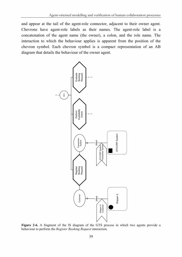
Figure 2-6 shows a segment of the IS diagram in Figure 2-3 that focuses on the Register Booking Request interaction. The human agent Shipper X and the software agent GTS ERP System are assigned to the roles Customer and Transaction System10. Both agents own a behaviour that is used to perform the interaction. In the IS diagram, the behaviours of the agents, which are playing the roles attached to the elementary interactions, are indicated by chevron symbols (see Figure 2-6). Chevron symbols represent the local behaviours of the agents on an abstract level
10 In a HCP, most interactions are performed between humans. This example is to illustrate that besides human agents it is possible to specify software agents as interaction participants, and also to model their behaviours (see below). The GTS ERP system could also be modelled as a synthetic agent and its modules as software agents for instance when it is desired to make explicit interactions between humans and certain ERP modules as part of the HCP.
Agent-oriented modelling and verification of human collaboration processes
39
and appear at the tail of the agent-role connector, adjacent to their owner agent. Chevrons have agent-role labels as their names. The agent-role label is a concatenation of the agent name (the owner), a colon, and the role name. The interaction to which the behaviour applies is apparent from the position of the chevron symbol. Each chevron symbol is a compact representation of an AB diagram that details the behaviour of the owner agent.
Figure 2-6. A fragment of the IS diagram of the GTS process in which two agents provide a behaviour to perform the Register Booking Request interaction.
SE
Q
Cu
stom
er
pla
ys
Tra
nsa
ctio
nS
yste
m
pla
ys
Pe
rfo
rmA
vaila
bili
tyC
hec
k
Eva
lua
teB
oo
kin
gR
eq
uest
Re
gis
ter
Bo
oki
ng
Re
que
st
GT
S E
RP
Sys
tem
:T
rans
actio
nS
yste
m
GT
S E
RP
Sys
tem
Sh
ipp
er
X
Shi
ppe
r X
:C
usto
mer

Chapter 2
40
Figure 2-7 shows the two AB diagrams that detail the chevron symbols in Figure 2-6. The two agents use these behaviours to perform the Register Booking Request interaction. An AB diagram is a swimlane that captures the intended behaviour of its owner agent. It depicts the internal states of the agent, and the communicative and non-communicative activities that cause it to change states. Each swimlane is marked with the agent-role label of the corresponding chevron. The messages sent and received by the agent are modelled explicitly as message places (see Figure 2-7).
Figure 2-7. The AB diagrams of the agents that are playing the roles attached to the Register Booking Request interaction in Figure 2-6.

Agent-oriented modelling and verification of human collaboration processes
41
AB diagrams are based on the Behaviour net formalism (Meyer & Szirbik, 2007a), an extension of the CP net formalism with the message place type. Message places enable the flow of tokens between the different agent behaviours in an interaction. In other words, different agent behaviours in an interaction communicate with each other through message exchange. The labels of message places act as their type names. These type names are useful to determine on which message place an incoming message is placed (e.g. the Booking overview message that is received by Shipper X). Message exchange is peer-to-peer, that is, if a certain agent sends the same message to two agents the (outgoing) message place is modelled twice in the AB diagram of this agent. This chapter assumes that any labels local to the agents are based on a common shared ontology of the business domain under consideration. Thus, agents use similar type declarations for matched message places and assign the same semantic meaning to these type names.
One or more modellers create AB diagrams. Data about human agent behaviours is preferably collected through one-to-one interviews with the involved process participants. Alternatively, non-intervening observation, study of organizational documentation (e.g. procedures, protocols, norms), and/or key informant consultations may be used. One or more of these data collection methods can also be employed to gather data about software agent behaviours (i.e. legacy system’s activities). Coarse-grained modelling of legacy systems’ activities in AB diagrams exposes their generic functionalities and interaction touch points. This helps to understand how humans interact with IT systems as part of the HCP under study. Moreover, it helps to clarify the boundaries between the HCP under study and the automated business processes (i.e. workflows). As mentioned before, also the behaviours of synthetic agents can be modelled in AB diagrams. In a multi-agent system development context, the formalized (human) behaviours can be used as executable specifications to directly code the behaviours of software agents that support the humans.
An agent can own multiple AB diagrams for each interaction in which it is involved. The associated chevron symbols may be drawn inside the owner agent. This means each agent can have a knowledge base of applicable behaviours in the form of AB diagrams. In the IS diagram, only the AB diagram that is selected for usage in an interaction is depicted (as in Figure 2-6). During enactment of the IS diagram by a multi-agent system, agents can make contextual run-time choices from their knowledge base of AB diagrams. The agents need to be implemented with a selection mechanism to identify and select an AB diagram for a given

Chapter 2
42
interaction. Based on the individual behaviour of an agent, there is no certainty that the behaviour(s) of the other agent(s) in the same interaction are matching the behaviour of the agent. If the agent behaviours are matching, the behaviours are said to be aligned. In aligned agent behaviours, the message places are exactly matched by number and type name (as in Figure 2-7).
The formalization of human, software, and synthetic agent behaviours in AB diagrams makes these behaviours explicit, which makes them amenable to analysis. As mentioned in Section 2.1, this chapter performs verification analysis to investigate the structural correctness and compatibility of the agent behaviours that perform a given interaction. For simple (intra-organizational) interactions with relatively simple agent behaviours or with only two involved agents, the modeller can manually achieve alignment by making sure each sending message place has a corresponding receiving message place of the same type in an AB diagram of another agent that is party in the interaction. However, for more complex interactions, with many inter-agent behavioural interdependencies or in modelling exercises where multiple modellers (from different organizations or organizational units) are involved, manual alignment is too difficult and error-prone. Using the proposed design-time verification method (see Section 2.4), the combined agent behaviours that result from the integration of the AB diagrams owned by the agents involved in a given (elementary) interaction can be verified for structural correctness and alignment. This implies that after any corrections and/or modifications, the execution of such an interaction is the coordinated execution of all the aligned agent behaviours involved.
AB diagrams allow beliefs about the contribution expected from other agents in the same interaction to be modelled. This allows an expected interaction to be modelled from the viewpoint of one agent. In this case, the AB diagram depicts the intended behaviour of the owner agent and the expected behaviours of other agents. Such an AB diagram is represented as a multi-swimlaned Behaviour net including message exchange points, and is named interaction beliefs in TALL. More detail about the interaction belief concept can be found in (Stuit, Szirbik, & de Snoo, 2007).
2.3.3. Formal definition: TALL process diagrams
The role of the graphical syntax, as presented in Section 2.3.2, is to allow easy interpretation of the diagrams by business users (Oude Luttighuis, Lankhorst, van de Wetering, Balb, & van den Berg, 2001). This section presents the formal definition that underlies the TALL process diagrams. This formal semantics not

Agent-oriented modelling and verification of human collaboration processes
43
only enables (future) execution of the diagrams in a multi-agent system, but also makes TALL more than simply a diagrammatic convention. Explanations of the individual parts of the formal definition are given immediately below it.
Definition 1 (IS and AB diagrams). The THCP model is a tuple (I, LI, <I, RT, R, LR, RI, A, LA, AR, AT, DR, AV, LAV, O):
a) I is the non-empty set of interactions and
b) LI: ILabelsI is the interaction labelling function that assigns a label to
each interaction and
c) <I I I is a relation such that:
<I is a partial ordering of I;
for any iI the set {sI | s <I i} is well-ordered;
L0 = {i0} with Lx = {iI | ht(i) = x} and ht(i) = |{sI | s <I i}|.
d) RT: I{SEQ, SEQd, PAR, PARd, XOR, XORd} is the routing type
function that assigns a routing type to each interaction. e) R is the non-empty set of roles and
f) LR: RLabelsR is the role labelling function that assign a label to each
role and
g) RI: RI is the role-interaction function that connects roles to
interactions. h) A is the set of agents and
i) LA: ALabelsA is the agent labelling function that assign a label to each
agent and
j) AR: AR is the agent-role function that assigns agents to roles and
k) AT: A{H, S, Y} is the agent type function that maps each agent to a
generic agent type: Human, Software, or sYnthetic.
l) DR: IDDRS is the decision rule function that assigns a decision rule set
DRS to each interaction that applies a decision rule with: ID = {iI | RT(i){XORd, SEQd, PARd}.
m) AV is the set of agent behaviours and
n) LAV: AVLabelsAV is the agent behaviour labelling function that
assigns a label to each agent behaviour and
o) O: AVA is the ownership function that assigns agents (read: owners) to
each agent behaviour.

Chapter 2
44
(a&b&c) The IS diagram is a graphical representation of an interaction tree. The interactions in the set I are the nodes in the tree that form the HCP under study. The set I is required to be non-empty because the root interaction is always defined for any HCP. Interactions in the IS diagram are denoted by interaction labels. Each interaction in the tree has a unique id. Therefore, interactions with identical labels, which are assigned by the labelling function LI, are allowed. Identically labelled interactions are different by their position and are unrelated when executed.
The partial ordering relation <I connects parents and their children, that is, it is a set of ordered pairs (i, s) where the first element is a parent interaction iI and the second element is a child interaction sI. The nodes in the tree immediately greater than (or succeeding) a node are called its children. The node immediately less than (or preceding) a node is called its parent (if it exists). Any node lesser than a node is an ancestor and any node greater than a node is a descendant. The partial ordering <I represents distance from the root and the well-ordering requirement ensures that each node has at most one parent, and therefore at most one grandparent, and so on. Nodes with no ancestors are roots: {iI | sI: s <I i}. Elementary interactions are nodes with no descendants: EI = {iI | sI: i <I s}. For any node, its set of ancestors is well-ordered. Hence, an ordinal that denotes height can be associated to any node: ht(i) = |{sI | s <I i}|. In this way, the x-th level of the tree is defined to be the set: Lx = {iI | ht(i) = x}. Consequently, L0 denotes the root level in the tree. The set L0 is required to be a singleton set to make sure there exists only one root interaction i0. Whenever a <<I b in I (i.e. interaction a is an immediate predecessor of interaction b), interaction a is placed higher than b in the IS diagram and there is a line drawn from interaction a to b (called an edge). In this way, movement downwards indicates succession. Graphically, the lines between each parent and its direct children converge in the routing type symbol that graphically appears below each parent.
Two auxiliary functions are defined to navigate the IS diagram. The function children(i) returns the set of direct children (i.e. immediate successors) of interaction i: children(i) = {sI | i <<I s}. Logically, the set children(i) is empty for an elementary interaction. The function parent(i) is used to denote the parent of interaction i: iI: [parent(i) = {sI | s <<I i}].
(d) Formally, each routing type is defined on a parent interaction. Graphically, in the IS diagram, routing types appear below parent interactions. The function rank
SI , based on Eshuis and Grefen (2008), is used to indicate the (sequential)
order of two or more children of parents with routing type SEQ or SEQd: SI = {s

Agent-oriented modelling and verification of human collaboration processes
45
children(i) | RT(i){SEQ, SEQd} |children(i)| > 1}. Graphically, in the IS diagram, the sequential order is determined by the relative horizontal positions of the child interactions, starting at rank zero and increasing with one unit from left to right.
(e&f&g) The set R contains all the roles that are relevant to the set of interactions I. Each interaction iI is required to have at least two roles attached: I = {iI | 2 rR: (r, i)RI}. Since the root interaction is always defined, the set R is required to be non-empty. The function RI connects roles to interactions such that each role rR belongs to an unique ordered pair (r, i) in RI. Whenever (r, i)RI, there is a line drawn between r and i in the IS diagram. When multiple agents play the same role in a given interaction, they are assigned to a single occurrence of that role.
(h&i&j&k) The set of agents A is built by identification of the agents in the business domain under consideration. Each agent is a human, software, or synthetic agent. Agents are denoted by agent labels. The function AR connects agents to roles such that each agent aA belongs to an unique ordered pair (a, r) in AR. Whenever (a, r)AR, there is a directed line drawn between a and r in the IS diagram. This line always carries the annotation plays (see Figure 2-6).
(l) The set ID contains all interactions with a routing type that needs to dynamically apply a decision (XORd, SEQd, and PARd). This decision can be generically expressed as a “rule”, called here decision rule. The function DR assigns a decision rule set to each interaction iID. The decision rule set manages the control flow of the direct child interactions of interaction i at runtime. A decision rule set can be viewed as a pseudo-workflow that is built upon implicit, explicit, and eventual formal business rules (Business Rules Group, 2000). In the abstract formal definition of the IS diagram, it is not necessary to specify the concrete syntax in which the rules are specified internally to the agents. The concrete syntax depends on the formal (rule-based) framework that is used to build the multi-agent system.
The business domain under consideration can adopt a multi-agent system for distributed HCP support that enacts the IS diagram, the associated (agreed upon) business rules, and coordinates the distributed agent behaviours. Based on the decoupling between the multi-agent interaction specification and the single agent behaviour specification (IS diagram vs. AB diagrams), all the decision rule sets should be separated from the agents. Moreover, they should be explicitly represented, as well as (possibly) dynamically inspectable and modifiable (Ricci,

Chapter 2
46
Omicini, & Denti, 2002). In this way, each decision rule set can be considered the formal expression of the business logic available and known to all agents involved in the execution of a certain HCP.
(m&n&o) The set AV contains all agent behaviours in the business domain under consideration. Graphically, the elements (read: agent behaviours) in this set appear in a compact form (as chevron symbols) in the IS diagram and as detailed agent behaviours (read: Behaviour nets) in the AB diagrams. Although agents can own multiple AB diagrams for the same interaction, the formal definition focuses on the behaviours selected and used by the agents to perform the interactions. These are also the relevant behaviours for design-time process verification (see Section 2.4). Agent behaviour labels are agent-role labels that mark the chevron symbols in the IS diagram and the swimlanes in the AB diagrams. Ownership of agent behaviours is set by the function O that assigns agent behaviours to agents such that each agent behaviour belongs to an unique ordered pair (av, a) in O. Agents that play a role, select and use one agent behaviour to perform the interaction. The composition RI AR of the functions AR and RI is a function from
the set of agents A to the set of interactions I: RI AR: AI. A pair (a, i) is only a
member of the composition if there exists a role rR and an agent aA that is connected to that role, and if the role is connected to the interaction iI: {(a, i)A I | rR: (a, r)AR (r, i)RI}. Whenever (a, i)RI AR, the selected agent behaviour (i.e. chevron symbol) is drawn at the agent side of the agent-role line with its arrowhead connected to the line (as in Figure 2-6). The auxiliary function ReturnAV(i) returns the subset of agent behaviours that are owned and selected by the role-playing agents involved in the elementary interaction iEI: ReturnAV(i) =
{avAV | aA: (av, a)O (a, i)RI AR iEI}. Logically, ReturnAV(i)AV.
2.3.4. Modelling guidelines and tool support
Modelling guidelines
Modellers can use the following guidelines to apply the TALL diagrams and the design-time verification method presented in this chapter. Understand the business domain under consideration The (lead) modeller builds an AS diagram of the agents in the business domain under consideration. The highest-level synthetic agent is the agent that contains the business entities, which form the team operating the HCP. These business entities

Agent-oriented modelling and verification of human collaboration processes
47
make up the first level of synthetic agents. In this way, the synthetic agent concept guides thinking in the initial modelling phase when the existing agents in the business domain are being identified. Next, lower-level synthetic agents (e.g. teams or departments) and the human agents that are members of the synthetic agents are identified. This activity may include an analysis of the current IT landscape to identify any software applications that interact with human agents or that may need to communicate with the (future) multi-agent system. These software applications are modelled as software agents in the AS diagram. Collect the necessary data The input to the TALL modelling activity is organizational documentation, interviews with process participants and/or experts, and any other data collection methods. The process participants play an important role because they are knowledgeable about the interactions and behaviours performed by them and colleagues, and the interrelations between all these interactions. Thus, the modelling effort is most advantageous when the business domain under consideration allows the human process participants to be actively involved. The modeller(s) has(have) the task to collect (local) process knowledge from the humans and formalize it in an IS diagram and associated AB diagrams. Build the IS diagram In this activity, the modeller(s) build(s) an IS diagram based on the collected knowledge/data. Since interactions and roles are strongly related, they can be modelled and named in parallel. Alternatively, a RS diagram can be created first (and updated later) to inform the creation of the IS diagram. The IS diagram is built using a top-down or bottom-up approach:
Top-down approach: start with the overall root interaction of the HCP and, based on the collected knowledge/data, decompose it in child interactions with the correct routing relations. Continue the decomposition process as long as child interactions can be identified;
Bottom-up approach: based on the collected knowledge/data, make a list of interactions and compose these into an IS diagram with correct routing relations.
In practical modelling exercises, a combination of these approaches is typically used.

Chapter 2
48
Assign agents to the roles and build AB diagrams For verification and execution purposes, it is sufficient to assign agents to the roles of elementary interactions only11. If any new agents are identified in this activity, the (lead) modeller updates the initial AS diagram. The modeller(s) detail(s) the behaviours of human, software and/or synthetic agents in AB diagrams. For human agents, this is preferably based on local process knowledge collected during one-to-one interviews. The intermediate output after this activity is an IS diagram and several AB diagrams that specify the agent behaviours. All diagrams can be validated together with (key) people from the business domain under consideration to check if the models reflect reality and user expectations. Translate the THCP model into a verifiable hierarchical CP net The proposed design-time verification method relies on existing formal methods and associated computer tools to determine the structural correctness of the THCP model (i.e. the combined interaction and behaviour diagrams). The entire THCP model is translated to a hierarchical CP net for verification purposes. Sections 2.4 to 2.6 explain in detail the verification method. Use CPN Tools to verify the hierarchical CP net This research adopts the CPN Tools software package (Jensen, Kristensen, & Wells, 2007) to execute formal verification of the CP net produced by the verification method. The TALL2HCPN translation software tool (see Section 2.5.2), which implements the set of translation functions that translate the THCP model to a hierarchical CP net (see Section 2.5.1), produces a CP net format that can be directly loaded in CPN Tools.
Toolset
A software toolset has been developed to support the TALL modelling language. The toolset includes the TALL Visual Editor that allows the user to build and manipulate TALL diagrams. The toolset is freely available from the software section on http://www.agentlab.nl/. The editor stores the diagrams and its modelling elements, including basic layout, positioning and relations between elements, in an associated database. Figure 2-8 shows the IS diagram of the GTS process in the editor without roles. In the drawing window, any element can be directly selected and moved. Moreover, the Visual Editor allows expand-and-
11 For descriptive purposes, agents can be assigned to any interaction in the IS diagram.

Agent-oriented modelling and verification of human collaboration processes
49
collapse navigation of complex interaction structures using a tree view control. To create and manipulate AB diagrams, the user can start a Behaviour net editor directly from the drawing window through a double click on an inserted chevron symbol. On save, a created AB diagram is stored in an XML-format in the database and linked to the specific chevron symbol. The Behaviour net editor is described in more detail in (Meyer & Szirbik, 2007b).
Figure 2-8. Screenshot of the TALL Visual Editor that shows the IS diagram of the GTS process.

Chapter 2
50
2.4. Verification of the THCP Model
2.4.1. The need for design-time verification
A HCP consists of many interacting agents that use their local behaviours to execute parts of the process autonomously. The design complexity of HCPs and the many execution interdependencies between the agents spurs the need for formal verification at design time. As mentioned in Section 2.1, design-time verification is concerned with determining whether a process model exhibits certain desirable structural properties before it is used for execution (Wynn, Verbeek, van der Aalst, ter Hofstede, & Edmond, 2009). Thus, the verification in this chapter is concerned with structural model checking. Section 2.4.2 defines structural correctness in more detail. A coherent and coordinated set-up of the agents is required, a setup in which the agent behaviours contain no structural design errors and inconsistencies. This means that the agents send each other the required messages to complete their behaviours, the interactions and thus the HCP instance. In a structurally correct model, each sending message place in one agent behaviour has a corresponding receiving message place in the behaviour of another agent. A HCP instance is a single enactment of a HCP, which is managed according to an IS diagram. A HCP instance is created when the IS diagram is initiated by an agent that is triggered12. Although an IS diagram can be used to manage a majority of HCP instances, each HCP instance is independently controlled and has its own process state and identity.
A multi-agent system is a complex system with high investment and critical requirements. A coherent and coordinated set-up of the agents, ensured at design time, enhances the reliability and quality of the process definition and the (future) multi-agent system that uses these process definitions to provide HCP support. Corrections made at process execution time can be very costly. Not only the flawed agent behaviours may need to be corrected and/or modified but also certain parts of running HCP instances may need to be redone, or even the whole HCP instance may need to start over, sometimes by applying costly rollback procedures. In the
12 A trigger is the recognition of some predefined set of circumstances associated with the operation of the entire process, which causes a particular action to be taken (WfMC, 1999). In an agent context, triggers can be seen as events that are perceived by the agents and cause them to initiate certain actions (Wagner, 2003). Either an external trigger (i.e. a communicative event like receiving a message) or an internal trigger (i.e. a non-communicative event like perceiving or sensing the status of an object) may activate an agent. Of course, event processing involves much more detail, that is, some form of internal agent processing is required in order for the agent to know how to react when facing a specific trigger.

Agent-oriented modelling and verification of human collaboration processes
51
case of several HCP instances being active simultaneously, or if performing certain activities is costly or is required to be timely, correcting agent behaviours at execution time is detrimental. Moreover, it may displease partners or customers, especially in distributed business settings where malfunctioning affects several organizations or organizational units.
2.4.2. A design-time verification method for agent-driven HCPs
The proposed design-time verification method consists of three sequential steps: (1) the translation of the THCP model to a hierarchical CP net, (2) the identification of process design errors in the hierarchical CP net, and (3) the correction and rollback of process design errors to the THCP model. Section 2.5 details the first step, and Section 2.6 details the second and third phase. The remainder of this section introduces relevant terminology.
In the first step, the THCP model is translated to a hierarchical CP net. In this way, the analysis power of CP nets can be leveraged and existing computer tools, which implement proven verification techniques, can be used. A single hierarchical CP net that combines the IS and AB diagrams is produced by the translation. In this way, a single executable model is obtained that can be checked for proper termination and completion. As mentioned in Section 2.3.2, the execution of an elementary interaction is the coordinated execution of the involved agent behaviours. After translation, the verification method checks the structural compatibility of the combined agent behaviours that have to complete a certain elementary interaction. Structural compatibility is ensured when the combined agent behaviours are structurally correct.
There are different ways to define structural correctness. The notion of sound workflow nets (van der Aalst, 1997; van der Aalst, 2000b), a special subclass of Petri nets, expresses correctness criteria that any workflow process should satisfy. A workflow is named sound, if and only if, it satisfies the following criteria:
Option to complete: for each token put in the start place, one (and only one) token eventually appears in the end place;
Proper completion: when a token appears in the end place, all the other places are empty;
No dead transitions: for each transition, it is possible to move from the initial state to a state in which the transition is enabled.
These correctness criteria are relevant to any executable business process model. Therefore, the proposed verification method uses the notion of soundness to check

Chapter 2
52
the structural correctness and compatibility of the agent behaviours in a given HCP. The verification method is execution-platform-independent and is concerned with design-time verification. The latter means that the method verifies the model before it is executed, and before full data and control features are added. Design-time verification ensures that there exists a scenario, which can successfully end through a specific set-up of agent behaviours for a certain interaction. At execution time, agents deal with a wide range of parameters and environmental factors. This may cause run-time errors and prevent proper HCP completion even if a model was found to be structurally correct at design time. In (De Backer, Snoeck, Monsieur, Lemahieu, & Dedene, 2009), the authors make an analogy with a labyrinth. At design time, it is verified whether there is a path that leads to the exit. At execution time, the interacting agents should try not to engage in a death-end path. This research is concerned with the former only. By performing model-based verification at design time, potential problems can be identified and resolved before the model is put into use (Wynn, Verbeek, van der Aalst, ter Hofstede, & Edmond, 2009).
2.5. Translation of the THCP Model to a hierarchical coloured Petri net
2.5.1. Translation: Formal definition
The formal definition consists of eleven translation functions (from now on: the translation technique) that map the IS diagram and the associated AB diagrams for a given HCP into a single hierarchical CP net (from now on: the produced CP net)13. The functions use the following notations from the formal definition of (hierarchical) CP nets (Jensen, 1994; Jensen, 1997):
a) is the finite set of non-empty types also called colour sets, P is the finite
set of places, T is the finite set of transitions, A is the finite set of arcs, S
if the finite set of subnets or pages, SNT is the set of substitution
nodes, and PNP is the set of port nodes. Places and transitions are both
referred to as nodes in a Petri net. In a hierarchical CP net, the substitution node or transition is the most important hierarchy construct (drawn as a
13 The formal definition of the THCP model, as presented in Section 2.3.3, is defined directly on its graphical syntax and is the starting point for the translation. Alternatively, the syntax of TALL could be translated to the syntax of hierarchical CP nets that already has a formal semantics. This is unwanted since hierarchical CP nets are neither agent-oriented nor interaction-centric. Moreover, ambiguities in the TALL diagrams, caused by the lack of a formal definition, can result in faulty Petri net models.

Agent-oriented modelling and verification of human collaboration processes
53
double-bordered transition). A substitution transition acts as the parent transition of a subpage that contains the detailed behaviour of the activity represented by the substitution transition;
b) C is the colour function that is defined from P into . C maps each place
to a colour set; c) SA is the page assignment function that is defined from SN into S. SA
relates substitution transitions to their subpages such that no page is a subpage of itself;
d) PA is the port assignment function. PA is defined from SN into binary relations that relate socket places on the super page (the places that surround the substitution transition) with port places on the corresponding subpage;
e) PT is the port type function that is defined from PN into {in, out, i/o, general};
f) ST is the socket type function that maps from pairs of socket places and substitution transitions into {in, out, i/o}. Related socket and port places must have matching socket and port types, and conceptually represent the same place (i.e. they always have identical markings);
g) N is the node function that is defined from A into P TT P. Thus, N maps each arc into a pair where the first element is the source node and the second the destination node;
h) In(x) returns the set of input nodes for a node x: In(x) = {x’X | a: N(a) = (x’, x)} and Out(x) returns the set of output nodes for a node x: Out(x) = {x’X | a: N(a) = (x, x’)}.
In addition, the following notations are introduced to support the translation technique:
LF is the hierarchical CP net Labelling Function. LF: XV where X = P
TA and V is a set of labels;
Net elements are augmented with a page index to refer to the elements on a specific page in the produced CP net. For example, Ps is used to denote the places and Ts is used to denote the transitions on page s. The page index is omitted when referring to the elements of the entire produced CP net;
There exists a one-to-one correspondence between the set SN of the produced CP net and the set of interactions I in the IS diagram. Based on
this, two bijective functions are defined: map1: ISN and map2: SNI.

Chapter 2
54
The former returns the corresponding substitution transition tSN of interaction iI while the latter returns the corresponding interaction iI of substitution transition tSN.
As Section 2.4.2 explains, the verification method abstracts away from data and control features. This impacts the routing types XORd, SEQd, and PARd, which make deterministic choices based on an evaluation of the data conditions in the attached decision rules. Therefore, the translation technique represents these deterministic choices as non-deterministic choices (see Figure 2-9).
Figure 2-9. Unfolding transitions to produce non-deterministic choices.
The following translation functions are augmented with figures for clarification (Figure 2-10 to Figure 2-13). In these figures, the socket type of a place is written in a small rectangle that appears below the place, at the right or left side, which indicates the transition on which the socket type is defined. The port type of a place is written in a small circle that appears below the place. Place labels are written inside the circles and (substitution) transition labels are written inside the squares.
Definition 2 (Translation Technique). The translation technique is formally defined by a set of eleven translation functions.
Translation Function 1 (RTF): Root Interaction Suppose: iI iL0. Then interaction i is the root interaction i0. The Root Translation Function RTF maps i0 into a page s*S (called the prime page) that contains substitution transition t1SNs with adjacent input and output places such that:
xnPs In(t1) = x1 Out(t1) = x2 ST(x1, t1) = in ST(x2, t1) = out LF(xn) = pn LF(t1) = map2(t1).

Agent-oriented modelling and verification of human collaboration processes
55
The prime page s* serves as the start page of the entire produced CP net. All the other pages are subpages of s*. Figure 2-10 shows three examples of the translation of a root interaction A using the function RTF.
In the IS diagram, routing applies to sibling interactions that are completed according to the routing type of their parent interaction i. The function children(i) returns the children of interaction i. The subsequent translation functions 2 to 8 translate, for each routing type, the sibling interactions into a subpage that manages the corresponding control flow.
Translation Function 2 (STF): Sequential Routing Suppose: iI RT(i){SEQ}. The Sequential Translation Function STF maps children(i) into a subpage sS that contains a finite non-empty sequence of substitution transitions t1, t2, …, tmSNs with adjacent input and output places such that:
k{1, .., |children(i)|}:[xnPs In(tk) = xk Out(tk) = xk+1 ST(xk, tk) = in ST(xk+1, tk) = out x1, xm+1PNs PT(x1) = in PT(xm+1) = out LF(xn) = pn LF(tk) = map2(tk)].
Figure 2-10a illustrates the translation of a set of sequential child interactions using the function STF. In the specific example of Figure 2-10a, children(i) contains three interactions. Translation Function 3 (SCF): Sequential Conditional Routing Suppose: iI RT(i){SEQd} |children(i)| > 1. The Sequential Conditional translation Function SCF maps children(i) into a subpage sS that contains a finite non-empty sequence of substitution transitions t1, t2, …, tmSNs with adjacent input and output places, and artificial control flow tasks for inclusive conditional sequential splitting- and joining-behaviour such that14:
k{1, .., |children(i)|}:[xnPs ynTs\SNs In(tk) = xk*2In(xk*2) = yk In(yk) = x(k*2)-1 Out(x(k*2)-1) = yk*2 (Out(tk), Out(yk*2) = x(k*2)+1) ST(xk*2, tk) = in ST(x(k*2)+1, tk) = out x1, x(m*2)+1PNs PT(x1) = in PT(x(m*2)+1) = out LF(xn) = pn LF(yn) = tn LF(tk) = map2(tk)].
Figure 2-10b illustrates the translation of a set of conditional sequential child interactions using the function SCF. As explained, the SEQd routing type is an OR-
14 In the translation functions, the * sign is the multiplication operator.

Chapter 2
56
split in which one or more interactions are executed at a time. When two or more interactions are enabled, they are executed in a sequence. On the subpage A#1 in Figure 2-10b, a non-deterministic choice is made either to execute the substitution transition tk or to bypass it.
Figure 2-10. Examples of the translation of a set of three sequential interactions (top), three conditional sequential interactions (middle), and a single child interaction that is iterated (bottom).

Agent-oriented modelling and verification of human collaboration processes
57
Translation Function 4 (SIF): Sequential Iterative Routing Suppose: iI RT(i){SEQd} |children(i)| = 1. Then children(i) is a singleton set {z}. The Sequential Iterative translation Function SIF maps children(i) into a subpage sS that contains substitution transition t1SNs with adjacent input and output places, and artificial control flow tasks for looping behaviour such that:
xnPs ynTs\SNs In(t1) = x1 Out(t1) = x2 Out(x2) = y1, y2Out(y1) = x1 Out(y2) = x3 ST(x1, t1) = in ST(x2, t1) = out(x1, x3PNs) PT(x1) = in PT(x3) = out LF(xn) = pn LF(yn) = tn LF(t1) = map2(t1).
Figure 2-10c illustrates the translation of a single child interaction B using the function SIF. At place x2, a choice is made either to repeat or not repeat t1. Because the choice to repeat transition t1 is non-deterministic, t1 can potentially be repeated infinitely and cause the entire hierarchical CP net (read: the HCP instance) to get locked in an endless loop. The definition of soundness assumes a notion of fairness, which means it is assumed that iteration does not violate the soundness requirements by postponing transition t2 indefinitely. The fairness assumption is reasonable since all choices are made (implicitly or explicitly) by agents that share and pursue a common (business) goal.
Translation Function 5 (PTF): Parallel Routing Suppose: iI RT(i){PAR}. The Parallel Translation Function PTF maps children(i) into a subpage sS that contains a finite non-empty sequence of substitution transitions t1, t2, …, tmSNs with adjacent input and output places, and artificial control flow tasks for parallel splitting- and joining-behaviour such that:
k{1, .., |children(i)|}: [xnPs ynTs\SNs In(tk) = xk+1Out(tk) = xk+m+1 In(xk+1) = y1 In(y1) = x1 Out(xk+m+1) = y2Out(y2) = x(m*2)+2 ST(xk+1, tk) = in ST(xk+m+1, tk) = out (x1, x(m*2)+2PNs) PT(x1) = in PT(x(m*2)+2) = out LF(xn) = pn LF(yn) = tn LF(tk) = map2(tk)].
Figure 2-11a illustrates the translation of a set of parallel child interactions using the function PTF. The transition y1 is used to produce tokens for all of the input nodes of the parallel substitution transitions tk. Similarly, the transition y2 is used to synchronize the parallel paths.

Chapter 2
58
Figure 2-11. Example of the translation of a set of three parallel interactions (top), three conditional parallel interactions (middle), and a single child that is performed a certain pre-defined number (5 in this example) of times in parallel (bottom).
Translation Function 6 (CPF): Conditional Parallel Routing Suppose: iI RT(i){PARd} |children(i)| > 1. The Conditional Parallel translation Function CPF maps children(i) into a subpage sS that contains a finite non-empty sequence of substitution transitions t1, t2, …, tmSNs with adjacent input and output places, and artificial control flow tasks for inclusive conditional parallel splitting- and joining-behaviour such that:
k{1, .., |children(i)|}: [xnPs ynTs\SNs In(tk) = xk+4Out(tk) = xk+m+4 In(xk+4) = yk*2 In(yk*2) = xk+1 In(xk+1) = y1In(y1) = x1 Out(xk+1) = y(k*2)+1 Out(y(k*2)+1) = xk+7 Out(xk+7) = y(m*2)+2 Out(y(m*2)+2) = x(m*3)+2 ST(xk+4, tk) = in ST(xk+m+4, tk) =

Agent-oriented modelling and verification of human collaboration processes
59
out (x1, x(m*3)+2PNs PT(r1) = in PT(x(m*3)+2) = out LF(xn) = pn LF(yn) = tn LF(tk) = map2(tk)].
Figure 2-11b illustrates the translation of a set of inclusive conditional parallel child interactions using the function CPF. The working of the PARd routing type is related to the SEQd routing type since it is also an OR-split that makes a choice between one or more children. However, when two or more interactions are enabled, they are executed in parallel. The subpage A#1 in Figure 2-11b first uses the transition y1 to enable parallel execution of all the children. Next, a non-deterministic choice is made either to execute the substitution transition tk or to bypass it. When the substitution transitions tk are not executed, the bypass route makes sure that the flow can continue by producing the needed tokens for the synchronizing transition y8.
Translation Function 7 (PIF): Parallel Iterative Routing Suppose: iI RT(i){PARd} |children(i)| = 1. Then children(i) is a singleton set {z}. The integer n is a counter that indicates how many times the single child should be performed in parallel. The Parallel Iterative translation Function PIF maps children(i) into a subpage sS that contains a finite non-empty sequence of substitution transitions t1, t2, …, tmSNs with adjacent input and output places, and artificial control flow tasks for parallel splitting- and joining-behaviour such that:
k{1,.., n}: [xnPs ynTs\SNs In(tk+1) = xk+1 Out(tk) = yk+m+1 In(xk+1) = y1 In(y1) = x1 Out(xk+m+1) = y2 Out(y2) = x(m*2)+2 ST(xk+1, tk) = in ST(xk+m+1, tk) = out (x1, x(m*2)+2PNs) PT(x1) = in PT(x(m*2)+2) = out LF(xn) = pn LF(yn) = tnLF(tk) = map2(tk)].
Figure 2-11c illustrates the translation of a single child interaction B using the function PIF. This translation is identical to the PAR routing type except that the number of parallel paths depends on the value of the counter. Interaction B needs to be performed at least once. In the TALL2HCPN translation software tool (see Section 2.5.2), the number of the counter is fixed arbitrarily at five and can be changed by the user in the TALL Visual Editor.
Translation Function 8 (ECF): Exclusive Conditional Routing Suppose: iI RT(i){XOR, XORd}. The Exclusive Conditional translation Function ECF maps children(i) into a subpage sS that contains a finite non-empty sequence of substitution transitions t1, t2, …, tmSNs with adjacent input and

Chapter 2
60
output places, and artificial control flow tasks for non-deterministic exclusive selective splitting- and joining-behaviour such that:
k{1, .., |children(i)|}: [xnPs ynTs\SNs In(tk) = xk+1Out(tk) = xm+2 In(xk+1) = yk In(yk) = x1 ST(xk+1, tk) = inST(xm+2, tk) = out (x1, xm+2PNs) PT(r1) = in PT(r2) = outLF(xn) = pn LF(yn) = tn LF(tk) = map2(tk)].
Figure 2-12 illustrates the translation of a set of exclusive conditional child interactions using the function ECF. The translation of the XORd routing type is the same.
Figure 2-12. Example of the translation of a set of three non-deterministic exclusive conditional child interactions.
Translation Function 9 (ABF): Agent Behaviour Translation
Suppose: iEI ReturnAV(i) . Then interaction i is an elementary interaction
with associated AB diagrams. The AB diagrams are returned by the function ReturnAV(i). The Agent Behaviour translation Function ABF uses the following notations:
s is the start place and f is the final place of the Behaviour net avAV that represents the intended behaviour of an agent such that: s, fPav and In(s),
Out(f) = ;
The output of ABF is the (sub)page sS. This page s is a union of the Behaviour nets avReturnAV(i). Hence, the net elements of s consist of all the combined elements of these Behaviour nets15:
15 Ts is the finite set of transitions, Ps is the finite set of places, MPs is the finite set of message places, FIs is the finite set of incoming arcs that connect (message) places and transitions, and FOs is the finite set of outgoing arcs that connect transitions and (message) places.

Agent-oriented modelling and verification of human collaboration processes
61
Ts = ( )av ReturnAV i
Tav , Ps = ( )av ReturnAV i
Pav , MPs = ( )av ReturnAV i
MPav , and As =
( )av ReturnAV i FIavFOav;
MPS is the set of message places for sending messages and MPR is the set of message places for receiving messages: MPSs = {mpMPs | Out(mp) =
}, MPRs = {mpMPs | In(mp) = } and MPSsMPRs = ;
MPM is the Message Place Matching function. It is defined from MPSs into MPSsMPRs. MPM relates message places for sending to message places for receiving such that:
Related message places appear in two agent behaviours involved in the same interaction: (mps, mpr)MPM(mps): [ iEI av1, av2ReturnAV(i) mpsav1 mprav2;
Related message places have identical data types: (mps, mpr)MPM(mps): [C(mps) = C(mpr)].
ABF maps ReturnAV(i) into a single “behavioural” subpage sS that details the behaviour of the substitution transition corresponding to the elementary interaction i. This subpage s contains the combined Behaviour nets and artificial control flow tasks (and adjacent input and output places) for parallel splitting and joining of the Behaviour nets such that:
k{1, .., |ReturnAV(i)|}: [xnPs yn, znTs In(sk) = y1In(y1) = x1 Out(fk) = y2 Out(y2) = x2 (x1, x2PNs) PT(x1) = in PT(x2) = out (p, p’)MPM(p): [(p, p’)Ps Out(p) = zn In(p’) = zn] p(PsMPs)\xn: LF(p) = LF(pav) tTs\{yn, zn}: LF(t) = LF(tav) LF(x1) = S LF(x2) = F LF(y1) = t1LF(y2) = t2 LF(zn) = dn.
Figure 2-13 illustrates the translation of an IS diagram where three agents bring behaviours to perform the elementary interaction C. The function ABF translates the AB diagrams into a single page C#2 that contains the three combined agent behaviours. Figure 2-13 shows that ABF connects pairs of matching message places to a shared transition that acts as a synchronization point between the agent behaviours. Message places are matched based on a simple rule. Each sending message place of an agent is matched with a receiving message place of another agent in the same interaction that has the same message type. If there are two agents with such a receiving place, only one pair is created since communication is considered to be peer-to-peer. Message places that do not have a matching message

Chapter 2
62
place are not attached to a shared transition. If such message places exist, the agent behaviours are not aligned. This can be resolved during the verification process where the behaviours can be corrected or modified (see Section 2.6.2). In the relatively simple example of Figure 2-13, all message places are exactly matched by type name and number, which results in four pairs of matched sending and receiving message places.
Figure 2-13. Example of the translation of an elementary interaction C and its associated AB diagrams.
Translation Function 10 (EIF): Pruning of Elementary Interactions The previous translation functions translate the interactions in the IS diagram into substitution transitions in the produced CP net. However, if elementary interactions have no associated AB diagrams, the corresponding substitution transitions have no subpages. IA is the set of elementary interactions that have no associated agent
behaviours: IA = {iI | iEI ReturnAV(i) = }. The Elementary Interaction

Agent-oriented modelling and verification of human collaboration processes
63
pruning Function EIF turns all substitution transitions that correspond to interactions in the set IA into “normal” transitions such that:
iIA: [map1(i)T SN\map1(i) pP: ST(p, map1(i)) = ].
Translation Function 11 (PLF): Page Labelling The function PLF is the Page Labelling Function. It is defined from S (the finite set of pages) into a set of page labels Z such that:
s = s*PLF(s*) = Root#0. The prime page s* receives Root#0 as its page
name.
s s*PLF(s) = LF(t)^#^ht(map2(t))+1 with tSN and SA(t) = s.
The operator ^ is the concatenation operator for text strings. Each page that is not the prime page is assigned a page label, which is a string concatenation of the label of the substitution transition on the super page of s, the # sign, and the interaction level or height on which interaction i appears (increased with 1). The requirement SA(t) = s makes sure that the label of the correct substitution transition is used, that is, the substitution transition that has page s as its subpage. Figure 2-14 shows the hierarchical CP net that results from the application of the translation technique to the IS diagram of the GTS process, as shown in Figure 2-3. All sets of sibling interactions are translated into subpages (from now on: interaction pages). The lowest-level “behavioural” subpages that contain the combined agent behaviours have not been included for reasons of brevity.
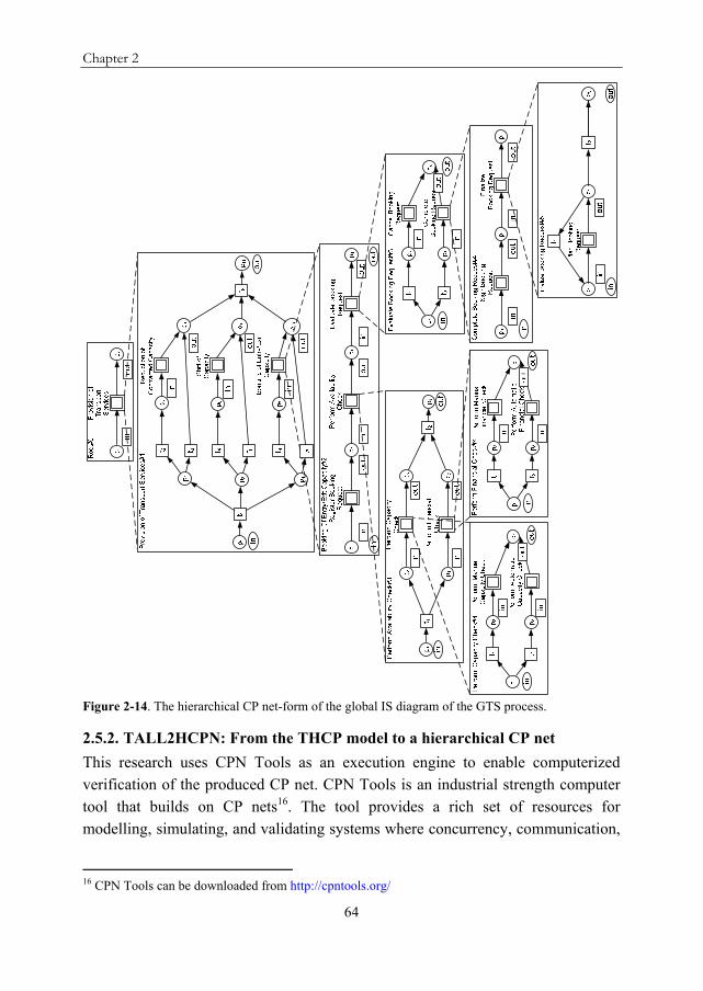
Chapter 2
64
Figure 2-14. The hierarchical CP net-form of the global IS diagram of the GTS process.
2.5.2. TALL2HCPN: From the THCP model to a hierarchical CP net
This research uses CPN Tools as an execution engine to enable computerized verification of the produced CP net. CPN Tools is an industrial strength computer tool that builds on CP nets16. The tool provides a rich set of resources for modelling, simulating, and validating systems where concurrency, communication,
16 CPN Tools can be downloaded from http://cpntools.org/

Agent-oriented modelling and verification of human collaboration processes
65
and synchronization play a major role (Jensen, Kristensen, & Wells, 2007). A tool named TALL2HCPN (here HCPN stands for Hierarchical Coloured Petri Net) implements the translation technique. TALL2HCPN is available as a plugin in the TALL Visual Editor. The bottom right part of Figure 2-15 shows the user interface of TALL2HCPN.
Figure 2-15. Screenshot of the TALL Visual Editor showing the drawing window, and the main window of the TALL2HCPN translation software tool.
TALL2HCPN takes its input from the currently active model database. The user can select a specific IS diagram and start the translation. During execution, TALL2HCPN queries the database to extract the elements of the selected diagram and automatically creates an XML-file that can be directly loaded in CPN Tools. The XML file created by TALL2HCPN contains the hierarchical CP net (its pages and page structure), the port assignment that links the pages, and the net elements for each page. CPN Tools requires all places to be typed and requires all arcs to carry an arc expression that evaluates to the type of the adjacent place. Therefore, TALL2HCPN assigns the empty colour set E to all places and the variable e to all arcs in the produced CP net. Tokens of type E are considered uncoloured or black tokens that carry no data (Jensen, 1994). Figure 2-16 shows the (partial) output of TALL2HCPN in CPN Tools for the THCP model shown in Figure 2-8 and Figure 2-15.

Chapter 2
66
Figure 2-16. Screenshot of CPN Tools in which the hierarchical CP net produced by TALL2HCPN for GTS is loaded.
2.6. The Verification Activity
2.6.1. Verification analysis
In the second step of the proposed verification method, verification analysis is performed to identify process design errors in the agent behaviours. CPN Tools is equipped with verification techniques. The state space analysis feature of CPN Tools is used to verify the soundness of the behavioural pages (i.e. the combined agent behaviours for each elementary interaction) in the hierarchical CP net produced by TALL2HCPN. When the state space tool in CPN Tools is applied, a state space graph is automatically calculated for all the pages in a (hierarchical) CP net17. From a state space graph, it is possible to answer a large set of verification questions concerning a CP net (Jensen, Kristensen, & Wells, 2007). CPN Tools
17 State spaces compute all reachable states and state changes in a CP net, and represent these as a directed graph where nodes represent states and arcs represent occurring events (Jensen, Kristensen, & Wells, 2007).
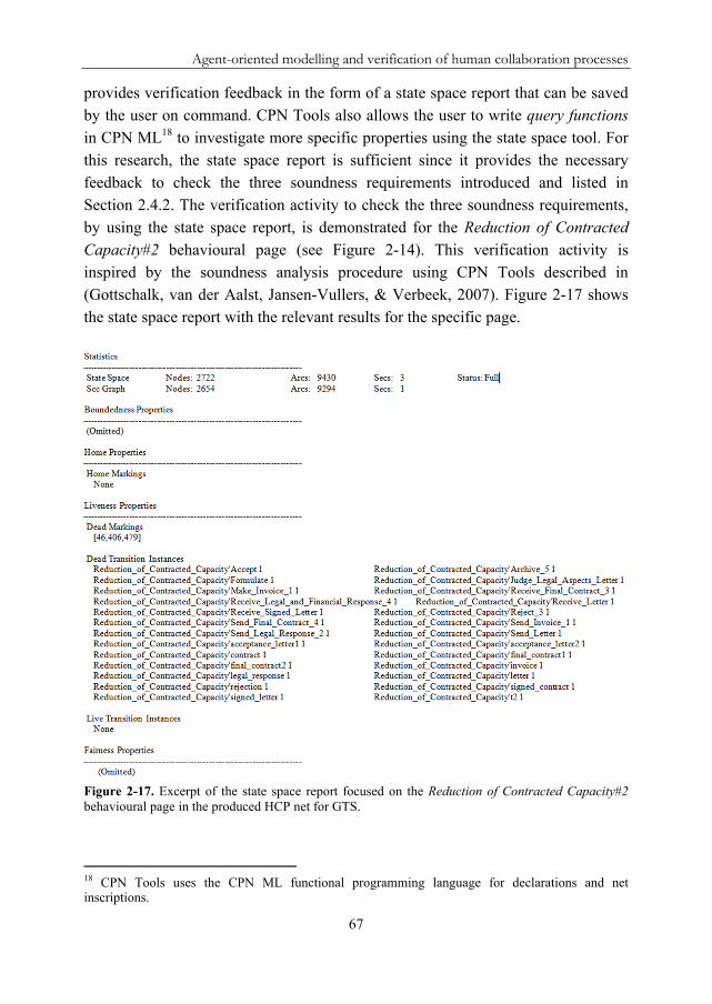
Agent-oriented modelling and verification of human collaboration processes
67
provides verification feedback in the form of a state space report that can be saved by the user on command. CPN Tools also allows the user to write query functions in CPN ML18 to investigate more specific properties using the state space tool. For this research, the state space report is sufficient since it provides the necessary feedback to check the three soundness requirements introduced and listed in Section 2.4.2. The verification activity to check the three soundness requirements, by using the state space report, is demonstrated for the Reduction of Contracted Capacity#2 behavioural page (see Figure 2-14). This verification activity is inspired by the soundness analysis procedure using CPN Tools described in (Gottschalk, van der Aalst, Jansen-Vullers, & Verbeek, 2007). Figure 2-17 shows the state space report with the relevant results for the specific page.
Figure 2-17. Excerpt of the state space report focused on the Reduction of Contracted Capacity#2 behavioural page in the produced HCP net for GTS.
18 CPN Tools uses the CPN ML functional programming language for declarations and net inscriptions.

Chapter 2
68
To test the first soundness requirement Option to complete, the list of dead markings is checked. Figure 2-17 shows that there exist three dead markings with node numbers 46, 406, and 479. These node numbers correspond to nodes in the state space graph generated by CPN Tools. CPN Tools can show the corresponding marking (i.e. the distribution of tokens over the places in the net) when the node descriptor for a node is expanded.
A HCP instance completes when a token appears on the output socket place on the root page in the produced CP net (this is the end state). In this case, all the underlying (interaction and behavioural) pages have successfully completed. Inspection of the node descriptor for node 46 revealed a token to be present on the end place p2 on the root page and on place p11 on the page Provision of Transport Services#1 (see Figure 2-14). These two places have identical markings because of the port assignment. This dead marking is expected since it corresponds to the end state of the HCP instance. However, the node descriptors for nodes 406 and 479 revealed non-empty (read: dead) markings on the behavioural page Reduction of Contracted Capacity#2. Clearly, these tokens are not in the end state of the HCP instance.
The State Space to Sim tool in CPN Tools is used to transfer the nodes that contain dead markings to the net simulator. Here, the design errors can be identified and the problem area(s) pinpointed in a certain agent behaviour. Transfer of nodes 406 and 479 to the net simulator, and subsequent analysis of the net structure revealed several flaws on the page Reduction of Contracted Capacity#2:
a) The first error is related to the scenario in which the capacity planner disapproves the request for reduction. In this case, the capacity planner simply ends the interaction without sending any message to the other agents. Thus, these agents wait endlessly for messages that are never received;
b) The second error is related to the scenario in which the capacity planner approves the request for reduction. When the customer receives the final contract and approval letter, it can either accept and sign both documents, or decide to reject them. The latter decision cancels the request for reduction. In this case, the behaviour of the customer needs to end by placing a token in its end place. In the current net structure, there is no separate path that properly ends the customer’s behaviour;
c) The third error occurs because the secretary agent does not have a separate path to handle the rejection, which means its behaviour is not ended properly. Therefore, the secretary’s behaviour deadlocks in the case of a

Agent-oriented modelling and verification of human collaboration processes
69
rejection since it also waits for the signed acceptance letter and contract that never arrives.
Correction of these three errors is required to complete the Reduction of Contracted Capacity interaction. After correction (Section 2.6.2 describes how to do this), the state space graph can be generated again to (re)check for soundness. If the state space report contains only the dead marking that corresponds to the end state of the HCP instance, the first soundness requirement is satisfied for the produced CP net. In general, when a token is encountered in a dead marking other than the end state of the produced CP net, the model is unsound and the non-empty (dead) markings should be inspected.
The second soundness requirement Proper completion is tested with the help of the root page in the produced CP net. The output socket place on the root page acts like a termination place that enforces Proper completion. This place only contains a token if all the underlying pages successfully completed. If this place contains no token when the HCP instance indicates completion, this means tokens reside in a state other than the end state, which is detected by the test for the first soundness requirement. The third soundness requirement No dead transitions is satisfied when there are no dead transition instances in the state space report (see Figure 2-17). Overall, the state space report that results from the application of the state space tool to the produced CP net for the GTS process revealed several process design errors in the agent behaviours on the Reduction of Contracted Capacity#2 behavioural page. This means that this page is unsound; the agent behaviours on this page are structurally incompatible.
The net elements of the interaction pages of a produced CP net always contain the same fixed (and sound) elements produced by the translation functions. The point is that it is sufficient to perform soundness checking on the behavioural pages. If all the behavioural pages are sound (and safe) then all their super pages (i.e. interaction pages) are also sound (and safe). This statement is based on the following theorem in (van der Aalst & van Hee, 2002): “If we have two sound and safe workflow nets V and W and we have a task t in V which has precisely one input and one output place, then we may replace task t in V by W and then the resulting workflow net is sound and safe again”. In the produced CP net, all the substitution transitions contain precisely one input and output place. Therefore, each substitution transition can be replaced by the net on its subpage without invalidating soundness.
Chapter 2
70
2.6.2. Verification reporting and correction
The third step of the proposed verification method is concerned with the rollback of the identified errors to the THCP model. For the moment, the correction of errors (i.e. agent behaviour redesign) is manual. The (lead) modeller identifies the soundness related errors in CPN Tools and, due to the ownership relation that is kept during translation19, he/she can identify those behaviours that contain the errors. The modeller then has two choices in terms of how the correction of the agent behaviours (i.e. the AB diagrams) is done.
The first option is to correct the error(s) in CPN Tools, generate the state space graph again, check if the errors have been resolved, adjust the initial AB diagram(s) in the TALL Visual Editor that led to the error(s), and send it back to the source agent. The second option is to pinpoint the problem area in CPN Tools, identify the agent(s) that is(are) responsible for the error(s), and communicate the error(s) to the respective agent(s) using the analysis report produced by CPN Tools as a feedback mechanism. These agents then have to send back a new version of their AB diagrams, and the modeller can check if the new models lead to a sound hierarchical CP net after applying the translation technique again. This is a typical distributed problem-solving situation. A middle solution is to send back to the agents a potential solution for correction (in the form of a structurally correct behaviour) to help them find better behaviours. The first reporting scheme takes away from the autonomy of the agents, but it is fast and effective. The second can be slow due to repetition of trial-and-error cycles of local redesign and central verification, but the agents have the autonomy to change their behaviours as they see fit.
The errors on the page Reduction of Contracted Capacity#2 were corrected using the first option. The corrected behaviours in CPN Tools have been used to correct the AB diagrams of the involved agents. In this specific case, the verification activity led to changes (i.e. improvements) in the behaviours of the customer, secretary, and capacity planner agents. After correction, the agent behaviours that perform the Reduction of Contracted Capacity interaction are structurally compatible. The errors in these agent behaviours demonstrate the importance of design-time verification. For example, in the case when the agent playing the role of capacity planner does not inform the other agents, the other agents have no way of knowing that the request for reduction was disapproved. In
19 The individual agent behaviours are marked in the behavioural pages of the produced HCP net by an agent-role label that appears above the behaviours.
Agent-oriented modelling and verification of human collaboration processes
71
real-life distributed business settings, where HCPs typically run, such deadlock situations occur easily since each agent uses its own local behaviour to perform its part in the process autonomously.
2.7. Discussion
The practical value of the TALL modelling language is that it provides for definition of a HCP’s multi-agent interaction structure (i.e. interactions, their composition and routing relations, their roles, and their participants or role-playing agents) and the local individual behaviours exhibited by the agents that perform the interactions. This makes the HCP explicit and amenable to valuable process analysis. Moreover, the language allows for organizational modelling of the business domain with the AS and RS diagrams. Based on this, the language meets the requirements mentioned in Section 2.3.1.
The ability to perform verification analysis to check the soundness of the THCP model is considered a desirable feature, as argued in Section 2.4.1. To enable soundness checking, the proposed verification method builds on the strong formalism and analysis capabilities of (hierarchical) CP nets. The method can be used as a tool by a business modeller, whose role is either to design new HCPs, either to identify and correct flaws in existing processes.
Like the proposed verification method, related research presents transformations from existing modelling languages (e.g. (A)UML, EPCs, BPMN) to Petri nets in order to exploit their strong analytical methods and computer tools (Ryu & Yücesan, 2007; Cabac & Moldt, 2005; Dijkman, Dumas, & Ouyang, 2008). The reader is referred to (De Backer, Snoeck, Monsieur, Lemahieu, & Dedene, 2009; Ryu & Yücesan, 2007) for a detailed discussion of several such transformations. In (De Backer, Snoeck, Monsieur, Lemahieu, & Dedene, 2009), the authors mention that in most approaches to verify a (collaborative) business process, a translation to a modelling language that supports formal analysis is used. In an agent-based system or model, the main difficulty is to decide what to verify and to what extent. The presented translation technique is different from other transformations in that it includes the multiple local behaviours of the agents involved in a HCP. In this way, the proposed verification method enables the verification of the structural correctness and compatibility of the combined agent behaviours that perform the (elementary) interactions. Most importantly, the method allows design errors to be traced back to individual agent behaviours. De Backer, Snoeck, Monsieur, Lemahieu, and Dedene (2009) argue that just computing global behaviour without

Chapter 2
72
mechanisms for tracing back potential difficulties to individual (local) business processes is not sufficient in practice.
The proposed verification method uses state space analysis to verify soundness. One of the disadvantages of using state space analysis is that it is not possible to obtain a full state space for very large and complex nets (Jensen, Kristensen, & Wells, 2007). In the proposed verification method, the number of tokens on the places in the produced CP net is bounded to one because each HCP instance is independently controlled. Model checking is decidable for bounded models (Eshuis, 2002). Moreover, the separation between interaction and behavioural pages allows the formal verification to be restricted to the most important aspects of the produced CP net, that is, the agent behaviours that perform the elementary interactions.
After rollback of the identified errors to the TALL diagrams, the verified TALL diagrams (i.e. IS and AB diagrams) can be used as sound executable specifications that can be subject to further analysis, design, simulation, and/or implementation. In a multi-agent system development context, the objective is to develop software agents for intelligent IT support of humans in their workplace interactions. Ongoing research is concerned with the use of business process gaming to develop these software agents. For this purpose, a series of tools form an integrated process gaming environment called the Agent Growing Environment (AGE) (Roest & Szirbik, 2009). The TALL diagrams drive the simulation, development, and deployment of software agents in AGE where gaming sessions (i.e. interactive simulations of the business process) are played with human experts or stakeholders from the business domain under consideration. The function of the IS diagram in these gaming sessions is to coordinate the enactment of the HCP by keeping track of the execution of interactions. At first, the interactions in the gaming sessions are completely performed by the humans. The AGE simulation environment logs the behaviours exhibited by the humans in AB diagrams. Next, software agents are developed based on the logged behaviours of the humans. This process is called “growing” the agents. Thus, the humans act as “instructors” to the software agents. The software agents are then brought into the game in new rounds of gaming sessions. Each round of gaming sessions will bring more automation to the game. This finally results in the situation where the software agents can take over some of the work of the humans in the (simulated) interactions.
Implementation of the proposed verification method as a “verification service” is the subject of further research in AGE. In this way, the behaviours of the human

Agent-oriented modelling and verification of human collaboration processes
73
and software agents in the gaming sessions can be checked for structural correctness and compatibility before the HCP is enacted in real-life. Successful scenarios can be discovered for one or more interactions, that is, the verification service cannot only be invoked for full HCP instances but also partial IS diagrams or individual interactions can be verified. In AGE, the verification method becomes more of an execution service instead of a design-time service. Currently, the verification reporting and correction is a manual step (see Section 2.6.2). One of the main requirements to make the gaming sessions effective in enacting a successful scenario using the valuable input of the human instructors is to automate the identification of the agents that invalidate soundness, and to automate the manual procedures of rollback to the TALL diagrams.
In a next phase of the HCP lifecycle, the business domain under consideration can adopt a multi-agent system to deploy the developed software agents in reality. The discovered successful scenarios, in terms behaviour models, can be used as sound specifications for the development of the software agents that make up the multi-agent system. Moreover, the multi-agent system can make use of the IS diagram to monitor and trace the interactions being executed in real-life. During execution, the IS diagram is a (partly) emergent artefact. Interactions may take place that were not modelled in the IS diagram, or modelled interactions may not occur. An algorithm has been developed that allows dynamic (structural) change of the IS diagram (Stuit & Meyer, 2009). This algorithm can be implemented in the multi-agent system to update the IS diagram in real time. After execution, the updated IS diagram serves as an execution log of the interactions in the HCP.
The internal processing component of the software agents in terms of process structure and execution code can be based on the verified AB diagrams. However, the use of explicit process models for the agents should not invalidate completely the autonomy of the agents. Especially in real-life, the majority of HCP instances require on-the-fly modification of behaviours because of the dynamic nature of the business context and the agents. Associated research explains how agents are implemented with alignment policies that enable them to dynamically modify their behaviours without invalidating (local) soundness (Meyer & Szirbik, 2007a). These alignment policies can be used during both design and execution time. Behavioural updates or even new behaviours can be introduced by modification of existing sound behaviour specifications. Changes to agent behaviours do not have ripple effects on the IS diagram because of the clear separation between interactions and behaviours in TALL.

Chapter 2
74
The use of the Behaviour net formalism for the internal processing component of the software agents does not restrict the applicability of the TALL diagrams to AGE. Several agent platforms require the communication architecture of a multi-agent system to be based on accepted standards (i.e. FIPA ACL) to ensure interoperability, but allow freedom in the formalism used for the individual processing component (i.e. the application-dependent behaviour) of the agents. For instance, the agent platform JADE imposes standards only for the external behaviour of the system components but leaves open the implementation details and the internal architectures (Bellifemine, Caire, Poggi, & Rimassa, 2003).
It is important to mention that a single superior general-purpose language is not advocated with TALL. Existing agent-based languages and development frameworks should be used to describe different aspects of a multi-agent system for HCP support, and to eventually build the software agents. Examples are the use of rule-based engines, agent development platforms and associated programming languages, agent communication architectures etc. The TALL-based set of descriptions should be considered as complementary to these, not as alternatives.
2.8. Related Work: Agent-Based Modelling
The TALL modelling language is inspired by the agent paradigm. The process diagrams in the language are concerned with the representation of agent interaction and behaviour. This section compares TALL to existing (agent-based) modelling languages concerned with agent interaction and behaviour specification. A comparison with several pervasive process modelling languages in the business process management community can be found in (Stuit & Szirbik, 2007).
2.8.1. Agent-based modelling languages for system design
A multitude of agent-oriented software engineering methodologies has appeared of which the most well-known are: MaSE (DeLoach, Wood, & Sparkman, 2001), Prometheus (Cheong & Winikoff, 2006; Padgham & Winikoff, 2003; Padgham & Winikoff, 2004), Tropos (Bresciani, Perini, Giorgini, Giunchiglia, & Mylopoulos, 2004), Gaia (Wooldridge, Jennings, & Kinny, 2000), and MESSAGE (Caire, et al., 2001; Caire, et al., 2002). Agent-based modelling languages are core components of these methodologies and many of them incorporate the same basic constructs as TALL (i.e. agents, roles, interactions, and behaviours). The most closely related modelling languages in terms of purpose or modelling constructs are the TROPOS language and MESSAGE. In addition, other agent-based modelling languages

Agent-oriented modelling and verification of human collaboration processes
75
include AUML (Bauer, Müller, & Odell, 2001; Odell, Van Dyke Parunak, & Bauer, 2000), AORML (Wagner, 2003), and AML (Cervenka, Trenanský, Calisti, & Greenwood, 2005; Cervenka, Trenanský, & Calisti, 2006; Trenanský & Cervenka, 2005). These agent-based modelling languages are UML-driven languages that include agent interaction and activity models. The interaction models are usually interaction protocols that specify the structured message exchange between agents and some constraints on the content of messages whereas the activity models specify the private plans, actions, or tasks of a single agent.
The agent interaction protocol (AIP) (Odell, Van Dyke Parunak, & Bauer, 2001)
allows hierarchical ordering using the UML package notation. This implies that an AIP can contain other AIPs, which allows for nesting. This nesting has similarities with TALL since a structure of nested interaction protocols can be seen as a tree. Within an AIP, a UML sequence diagram describes the inter-agent transactions that are needed to implement the protocol, in terms of sequencing and eventual message branching. The lifeline of a receiving agent of a multiple branched message has to follow the same logical expression. This is done (probably) to avoid deadlocks, but it is very rigid. When nested, the lower level of detail can use UML activity diagrams, state diagrams, sequence diagrams, or collaboration diagrams. This makes the tree very diverse in terms of representations. This notation is clearly semi-formal and cannot be used for design-time verification. The AIP is a software-engineering concept, and its high degree of variety can confuse a business modeller and its stakeholders. Another similarity to TALL is that at the lowest level of detail, an activity diagram can represent the behaviour of an agent. The AIPs, which include the message exchange between agents, are fixed at design time, and the agent behaviours are selected at runtime. In TALL, the specification of the message exchange structure is done, from a local perspective, in the AB diagrams. Thus, a fixed pattern of message exchange is not imposed on the interaction level. Moreover, the IS diagram relates interactions through both routing and composition. The UML sequence diagram does not reveal how an interaction is related to other interactions as part of a business process. Consequently, the IS diagram provides a better basis for process design, analysis, and improvement.
The TROPOS modelling language uses AIPs to represent (synchronous) communication between agents. Moreover, plans, as ways to achieve an individual agent’s goals can be detailed by representing them with UML activity diagrams. A step forward in MESSAGE is the decoupling between generic interactions and the
Chapter 2
76
way they are performed and structured, and the explicit guidelines provided to support the modelling exercise. However, the interaction view in MESSAGE does not present a process-oriented view of interactions with composition and routing relations. In addition, MESSAGE provides no explicit support for process verification.
Sturm, Dori, and Shehory (2003) describe an enhanced version of the OPM modelling framework called OPM/MAS that is specifically suited for agent systems. Although a good alternative for the UML-driven languages, OPM/MAS is a system modelling framework that addresses a number of essential software engineering issues (like accessibility and expressiveness aspects), and is useful primarily for system architects and developers. In (Hahn, Madrigal-Mora, & Fischer, 2008), the authors present the PIM4Agents metamodel for agent systems that abstracts from the specific requirements of existing agent-oriented software engineering methodologies, programming languages, and platforms. PIM4Agents is focused on the specification of software services and interfaces required by certain agent platforms. Thus, it deals with system and implementation details instead of business process concepts. In sum, all of the languages and frameworks discussed in this section focus on software development activities for agent systems. They provide a set of behavioural, functional, and structural views on the architectural design of the system and its components (i.e. agents). From the start, the goal is to derive system functionalities instead of describing business processes.
2.8.2. Agent-driven workflow and the use of Petri nets
JBees (Ehrler, Fleurke, Purvis, & Savarimuthu, 2006; Savarithmu, Purvis, & Purvis, 2005) is an agent-based workflow management system that uses CP nets as its process definition formalism. The JBees system implements a distributed network of autonomous agents each responsible for certain work associated with the running workflow process. A top-level CP net is separated in subnets, which are managed and executed by different agents. ADEPT (Jennings, Faratin, Norman, O'Brien, & Odgers, 2000; Jennings, Faratin, Norman, O'Brien, Odgers, & Olty, 2000) provides an infrastructure for the (conceptual) design and implementation of agent-based business process management systems. The different components of a business process are each represented by an autonomous agent. Automated negotiation is used for coordination and management of agent dependencies. Both in JBees and ADEPT, agents must adhere to a pre-defined negotiation protocol, which suffers from the same limitations as the AIPs discussed in Section 2.8.1. Moreover, there is no explicit support for design-time process verification.

Agent-oriented modelling and verification of human collaboration processes
77
Brahms (Sierhuis, Clancey, & van Hoof, 2007) is a modelling and simulation environment for analysing and supporting human work practice in organizations with intelligent software agents. The core of the Brahms model is the activity model that is dependent on internal reasoning, interaction with other agents, and interaction with the environment. WADE (Caire, 2008) is a software platform (built on top of JADE) that facilitates the development of distributed agent applications. WADE agents are embedded with lightweight workflow engines to execute tasks defined as workflows. Both Brahms and WADE are implementation frameworks that lack graphical representations to which business modellers can relate. These frameworks are not useful for business analysts or architects that want to capture, model, analyse, and/or improve HCPs.
Calisti and Greenwood (2008) present a goal-oriented approach towards business processes that consists of a process modelling language, named GO-BPMN, and a business process management system, named LS/ABPM. A strength of GO-BPMN is the clear orientation towards business people. The GO-BPMN language makes a clean separation between goals and the plans that achieve them. At first, processes are described as goal hierarchies. Every leaf goal is then linked to one or more plans that achieve the goal by execution of functional tasks. Likewise, the elementary (or leaf) interactions in the TALL IS diagram are performed by two or more agent behaviours. The IS diagram allows the interactions between participants to be made explicit using a hierarchical tree layout. GO-BPMN allows to specify goal hierarchies instead of interaction hierarchies. A goal describes motivation (i.e. internal behaviour) whereas an interaction describes a collaborative activity (i.e. external behaviour) (Jennings, Faratin, Norman, O'Brien, & Odgers, 2000). The GO-BPMN models are directly executable in the run-time environment of the LS/ABPM suite. This allows the user to test the model but an option to verify either the goal hierarchy or the plans is not offered. Testing shows the presence of errors but not their absence (Eshuis & Grefen, 2008). Finally, the agent-orientation of the entire approach resides mainly in the architecture of the system (and not in the modelling language) in which each process instance is interpreted and run by a software agent.
Several researchers (Adams, ter Hofstede, Edmond, & van der Aalst, 2006; Buhler & Vidal, 2005; Chang & Scott, 1996; Chen & Chung, 2006; Hawryszkiewycz & Debenham, 1998; Huang, Trappey, & Yao, 2006; Joeris, 2000; Palacz & Marinescu, 2000; Singh & Huhns, 1999; Tarumi, Kida, Ishiguro, Yoshifu, & Asakura, 1997; van der Aalst, Barthelmess, Ellis, & Wainer, 2001;

Chapter 2
78
Verginadis & Mentzas, 2008; Wang & Wang, 2005; Yan, Maamar, & Shen, 2001) present or argue in favour of agent-oriented workflow approaches or systems. A (compact) overview is provided by (Thimm & Will, 2004). In essence, most of these approaches focus on the use of agents as part of the architecture and/or infrastructure associated with the workflow management system, or focus on internal agent (implementation) details. Some of these works (Buhler & Vidal, 2005; Joeris, 2000; Palacz & Marinescu, 2000) allow for a (graphical) representation of agent behaviours using Petri nets, which enables validation and verification. However, their graphical representations are limited to the specification of agent behaviours using traditional task-centric process models. In such models, interaction representation is weak, as argued in Section 2.3.1. In these languages, it is not possible to model multi-agent interactions separately from the single agent behaviours.
Other related research is concerned with the application of different types of Petri nets to the agent domain. This research includes:
the use of CP nets and CPN Tools to model and/or analyse agent interaction protocols, and agent negotiation processes (Bacarin, van der Aalst, Madeira, & Medeiros, 2007; Billington & Gupta, 2007; Hanachi & Sibertin-Blanc, 2004);
the use of (hierarchical) CP nets (and other Petri net variants) to study and analyse multi-agent system plans (Oliveira de Almeida, da Silva, Perkusich, & de Barris Costa, 2005; Xu, Volz, Loerger, & Yen, 2002);
the use of CP nets to study agent social systems or social aspects (Costa Miranda & Perkusich, 1999; Weyns & Holvoet, 2002);
the use of CP nets (and other Petri net variants) to specify and analyse agent interaction and behaviour, or to specify the structure of distributed software systems (Camargo-Santacruz, Frausto-Solís, & Ramos-Quintana, 2005; Decker & Weske, 2007; Köhler, Moldt, & Rölke, 2001; Lian & Schatz, 2008; Lin & Norrie, 2001; Miyamoto, Sakamoto, & Kumagai, 2007; Moldt & Wienberg, 1997).
In these Petri net-based approaches, the focus is not on business processes modelling and/or analysis. Their emphasis is on system interaction and behaviour, and (agent) implementation details.

Agent-oriented modelling and verification of human collaboration processes
79
2.9. Conclusions
This chapter argues that the development of multi-agent systems for the support of HCPs via software agents should start with a proper (agent-oriented) understanding of the work practice of the agents in the business domain under consideration. On the one hand, existing agent-based development methodologies and modelling languages are software engineering approaches that focus on system specification instead of business process specification. On the other hand, existing business process modelling languages do not provide effective notations that suit the characteristics of HCPs. Most notably, their representation of the process structure of interactions in a HCP is weak, and they do not allow to model explicitly the individual local behaviours of the interaction participants.
The first part of this chapter presents an interaction-centric business process modelling language for HCPs, named TALL, inspired by the agent paradigm. The main modelling concepts in the language are agents, roles, interactions, and behaviours. To model a HCP, TALL separates between the high-level multi-agent interaction structure and the single agent behaviours that perform the interactions. The former is depicted in the Interaction Structure diagram that allows for hierarchical description of interactions, their composition and routing relations, and their roles in a tree layout. This diagram scopes the interaction context in which the agents behave. The local agent behaviours are represented in Agent Behaviour diagrams. The novelty of the language is that it is in line with a process-oriented approach (in which business processes are explicitly described) but with a focus on interactions and behaviours, which results from the agent-orientation. A visual editor is available to create and manipulate TALL diagrams. A case study of a real-life HCP at a Dutch gas transport company is used to illustrate the language.
Explicit process models can be verified using formal methods. This is the subject of the second part of this chapter. The autonomous behaviours of the agents and their situated nature may give rise to structural incompatibilities that can prevent proper completion of a HCP instance. Therefore, design-time verification is considered necessary to ensure the existence of a successful scenario that can complete a given HCP. A design-time verification method is presented that allows to verify the structural correctness and compatibility of the combined agent behaviours that perform the interactions in the HCP. The proposed verification method translates the Interaction Structure diagram and associated Agent Behaviour diagrams to a hierarchical coloured Petri net. This enables the application of proven computerized analytical methods and tools for Petri nets. An

Chapter 2
80
implemented software tool converts the TALL diagrams, created in the visual editor, into a Petri net format specific to the widely used CPN Tools software package. After translation, the state space analysis feature of CPN tools is used to identify process design errors in the agent behaviours, which are then rolled back to the TALL diagrams. The result is a set of verified Agent Behaviour diagrams that can be used for further analysis, design, simulation, and/or implementation purposes. The proposed verification method is applied to some of the agent behaviours from the case study and the results are discussed. Overall, the method allows business modellers to enhance the reliability and quality of the TALL HCP design, and the (future) multi-agent system that uses the design to provide HCP support.
There are limitations to the TALL modelling language as it currently stands. Further work remains to be done to apply and test the language both in theory and in practice. Feasibility of the language is to be demonstrated by an evaluation of TALL against a generic set of (interaction) patterns (Barros, Dumas, & ter Hofstede, 2005; van der Aalst, ter Hofstede, Kiepuszewski, & Barros, 2003). This allows to prove that the IS diagram is expressive enough to model common process modelling patterns.
TALL is not a general-purpose modelling language but is to be used in conjunction with other languages and (agent-oriented) development frameworks. In this regard, TALL can be the starting point for many possible research directions and applications. With regard to IT support, ongoing work is directed towards the link between the TALL modelling language and the software agent development process in AGE. In this context, future work is concerned with the enactment of the IS diagram to coordinate gaming sessions (i.e. interactive simulations of the business process with human participants/experts) to develop software agents for intelligent IT support of humans in their workplace interactions. In AGE, attention is to be given to the rollback of design errors in an automated way and the implementation of the verification method as a service that can be invoked both at design and implementation time.
In the near future, several other research directions are to be explored. First, the IS diagram currently supports composition and routing relations between interactions. Several other relations are to be investigated, in particular resource, goal, and data dependencies. Related to resource dependencies, the nature of roles and agent groups is to be investigated in more detail as a way to make sure that the role-playing agents in the IS diagram are authorized and skilled to do so. This

Agent-oriented modelling and verification of human collaboration processes
81
requires a more elaborated mechanism for authorizations, and an explicit representation of role permissions and agent groups. Agent groups are generic sets of agents with similar skills. Related to goal dependencies, an explicit representation of goals is currently missing in the language. There is a strong conceptual link between business processes, interactions, agents, and goals. Future work intends to explore the nature and applicability of this link. Related to data dependencies, data compatibility between interactions is to be explored to make sure that data can traverse from interaction to interaction when the IS diagram is enacted (see below).

Chapter 2
82
Chapter 3
An algorithm to integrate local interaction diagrams in human collaboration processes
This chapter is an edited version of the manuscript: Marco Stuit and Gerben G. Meyer. Agent interaction modelling based on product-centric data: A formal method to improve enterprise interoperability. In: K. Fischer, J.P. Muller, J.J. Odell, A.J. Berre (Eds.), Agent-Based Technologies and Applications for Enterprise Interoperability, Lecture Notes in Business Information Processing, 25, pp. 197-219. Heidelberg, Berlin, Germany: Springer, 2009.

Chapter 3
84
Abstract
his chapter shows how organizations can use product-centric data to produce local interaction representations of the interactions with and between their partners. An interaction-centric business process modelling
language named TALL, which is both graphical and formal, provides notations and diagrams to create these representations. A novel algorithm is introduced that enables partners to automatically integrate multiple local interaction diagrams into a global interaction diagram. This global interaction diagram improves enterprise interoperability since it increases overall process visibility. A process example of a simplified collaborative supply chain is used to exemplify the algorithm.
T

An algorithm to integrate local interaction diagrams in human collaboration processes
85
3.1. Introduction
Nowadays, there is an ongoing trend towards the provision of business processes that are collaborative of nature. Such business processes are provided by autonomous partners, which together deliver complex products and/or services in a collaborative network (Camarinha-Matos & Afsarmanesh, 2005; Moitra & Ganesh, 2005; Zacarias, Pinto, Magelhães, & Tribolet, 2009). This is explicitly shown by the emergence of new organizational forms like the networked or virtual enterprise (Jagdev & Thoben, 2001). The distributed nature of collaborative business settings is a good match for agent technology (Presley & Liles, 2001; Taveter & Wagner, 2002). The autonomous partners in such business settings can be seen as agents that execute certain tasks locally, while the interactions between the partners can be seen as interactions in a multi-agent system. To capture these interactions, the TALL modelling language has been developed (Stuit & Szirbik, 2007; Stuit & Szirbik, 2009; Stuit & Wortmann, 2010). TALL is an interaction-centric business process modelling language, based on agent-oriented concepts and notations, to model the process structure of interactions that makes up a human collaboration process (HCP). The algorithm presented in this chapter adopts the language to create graphical interaction diagrams.
The manufacturing industry is increasingly moving from a supplier-driven to a customer-driven market. This transition is a great challenge to the manufacturing process itself since it must be more flexible and robust as well as demonstrate enhanced scalability (Bussmann & Schild, 2000). Supply chains are evolving to keep in line with these developments. This is particularly shown by the move from conventional location-centric supply chains to product-centric supply chains (Holmström & Främling, 2006), as shown in Figure 3-1. A conventional supply chain is based on a systems design that is focused on location-specific material accounts and transactions between locations. In contrast, a product-centric supply chain is based on a systems design that tracks and controls individual products independently of the location and the ownership of the product individual. Callon, Méadel, and Rabeharisoa (2002) explain that product-centric control makes explicit the role of the product as the coordinating entity in the delivery of customized products and services.

Chapter 3
86
Figure 3-1. Location-centric (left) and product-centric supply chains (right). Source: (Holmström, Kajosaari, Främling, & Langius, 2009).
Product-centric control is the focus of the TraSer project20, in which control efforts are directed at individual products of the value-adding (supply) network. The idea behind product-centric control is that individual products and their components are the basic entities in the information system rather than orders, production orders, or shipment batches. In the TraSer approach, each product is labelled with an RFID or barcode, which contains an ID@URI code (Huvio, Grönvall, & Främling, 2002). With this ID@URI code, each product carries a unique identification number (ID), as well as a reference (Uniform Resource Identifier) to the location of a database where product-centric data is stored. In this way, each partner in the supply chain can access this data, which results in product visibility throughout the supply chain.
Product-centric data is information that is linked to individual products to meet information management needs of partners and/or customers at the level of the individual product (and its components). Such needs usually arise in supply networks for tracking and logistics control (Kärkkäinen, Ala-Risku, & Främling, 2003). To collect and share product-centric data, peers can directly interact with an information-based representation of a product. This information-based representation acts like an interface to a company-specific database that stores and maintains the product-centric data. The connection between the physical product and the information-based representation is usually made using a tag (e.g. RFID tag) and a reader (e.g. a handheld RFID reader) (Meyer, Främling, & Holmström, 2009).
20 http://www.traser-project.eu

An algorithm to integrate local interaction diagrams in human collaboration processes
87
The product visibility that results from the use of product-centric control in the network does not imply process visibility. This chapter proposes to use product-centric data to identify the multiple interactions between the different partners in a supply chain. Together these interactions form a HCP. Currently, none of the partners has a global view of the entire HCP in the supply chain, as each partner only has data about their interactions with direct partners. To increase interoperability between the partners, it is considered beneficial to build a global interaction diagram, which gives and end-to-end overview of the HCP. By using the product-centric data available in the supply chain, each partner is enabled to identify and model the local interactions of partners in local interaction diagrams. This chapter presents a novel algorithm, named the Global Construction Algorithm (GCA), which enables partners to automatically integrate the local interaction diagrams into a global interaction diagram. This global interaction diagram realizes improved understanding and insight in the supply chain’s HCP for a given partner. The goal of GCA is to build a minimal global interaction diagram where interactions from different local interaction diagrams are merged when there is no conflict. A conflict indicates the existence of alternative local views on the same interaction. GCA assumes a common shared ontology in the business domain under consideration. Ontology matching is outside the scope of this chapter.
This chapter is structured as follows. Section 3.2 introduces the notations of the TALL interaction diagrams. Next, Section 3.3 shows an example HCP, concerned with a simplified supply chain, in which product-centric data is used to build local interaction diagrams. After, Section 3.4 presents GCA. Section 3.5 applies GCA to the case example. After, Section 3.6 presents a discussion together with future work. Finally, Section 3.7 gives conclusions.
3.2. The TALL modelling language
TALL is an interaction-centric business process modelling language inspired by the agent paradigm (Stuit & Szirbik, 2007; Stuit & Szirbik, 2009; Stuit & Wortmann, 2010). The language is both formal and graphical. The organizational context in which a HCP occurs is seen as a multi-agent environment in which different agents behave in interactions to coordinate their work. The language explicitly recognizes interaction as the core activity in collaborative organizational work.
The TALL Interaction Structure (IS) diagram represents the interactions in a given HCP. In the IS diagram, interactions are represented by flattened hexagons, and are related to other interactions through composition (one interaction being
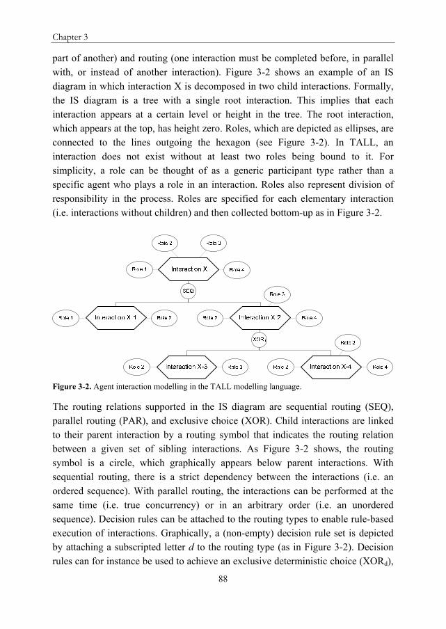
Chapter 3
88
part of another) and routing (one interaction must be completed before, in parallel with, or instead of another interaction). Figure 3-2 shows an example of an IS diagram in which interaction X is decomposed in two child interactions. Formally, the IS diagram is a tree with a single root interaction. This implies that each interaction appears at a certain level or height in the tree. The root interaction, which appears at the top, has height zero. Roles, which are depicted as ellipses, are connected to the lines outgoing the hexagon (see Figure 3-2). In TALL, an interaction does not exist without at least two roles being bound to it. For simplicity, a role can be thought of as a generic participant type rather than a specific agent who plays a role in an interaction. Roles also represent division of responsibility in the process. Roles are specified for each elementary interaction (i.e. interactions without children) and then collected bottom-up as in Figure 3-2.
Figure 3-2. Agent interaction modelling in the TALL modelling language.
The routing relations supported in the IS diagram are sequential routing (SEQ), parallel routing (PAR), and exclusive choice (XOR). Child interactions are linked to their parent interaction by a routing symbol that indicates the routing relation between a given set of sibling interactions. As Figure 3-2 shows, the routing symbol is a circle, which graphically appears below parent interactions. With sequential routing, there is a strict dependency between the interactions (i.e. an ordered sequence). With parallel routing, the interactions can be performed at the same time (i.e. true concurrency) or in an arbitrary order (i.e. an unordered sequence). Decision rules can be attached to the routing types to enable rule-based execution of interactions. Graphically, a (non-empty) decision rule set is depicted by attaching a subscripted letter d to the routing type (as in Figure 3-2). Decision rules can for instance be used to achieve an exclusive deterministic choice (XORd),

An algorithm to integrate local interaction diagrams in human collaboration processes
89
or to make an inclusive choice for N-out-of-M direct children. In the latter case, when N 2, the children are executed in sequence (SEQd) or in parallel (PARd). Graphically, for the SEQ and PAR routing types (with or without decision rules), sibling interactions are laid out linearly in the order of execution with the first interaction on the left. In Figure 3-2, interactions X-1 and X-2 are performed in sequence to complete interaction X. Interaction X-2 is completed by either interactions X-3 or X-2. In general, a parent interaction completes when its child interactions complete according to the specified routing relation. Thus, by convention, completion or composition is read bottom-up while routing between sibling interactions is read from left to right. In this chapter, the IS diagram is used to represent the interactions between agents in a supply chain.
A visual editor is available for the TALL modelling language to build and manipulate TALL diagrams. Moreover, a software tool, named Local IS Integrator (LISI), which works on the database created by the visual editor implements GCA. All software tools are freely available from the software section on http://www.agentlab.nl/.
3.3. Product-Centric Case Example
This section presents an example HCP from the perspective of one agent in a supply chain. The example HCP is used to illustrate how this one agent can build a global IS diagram of the supply chain using local process information (i.e. interactions this agent has with its direct partner agents) and product-centric data, which is linked to individual products. The example HCP is a simplified supply chain, based on (Collins, Aruachalam, Sadeh, Eriksson, Finne, & Janson, 2006), in which agents have the shared goal of delivering Personal Computers (PCs) to end customers. Figure 3-3 shows a high-level picture of the example HCP.
Figure 3-3. The simplified collaborative supply chain.
Supplier of HDDs
Supplier of CPUs
…
Manufacturer Retailer Customer

Chapter 3
90
In this supply chain, several supplier agents deliver computer parts to a manufacturer agent, who assembles the computer(s), and ships them to a retailer agent. The retailer agent sells the assembled computer(s) to a customer. Here, the focus is on the view of the retailer agent in the example HCP. The retailer can build a (local) IS diagram of its interactions with its direct partner agents. This diagram is shown in Figure 3-4. The roles are omitted in this diagram for clarity reasons. However, the agents are playing their given roles as supplier, manufacturer, retailer, or customer. As can be seen in the diagram, the root interaction of the retailer agent is Deliver PCs, which is also the common shared goal of the entire supply chain. To achieve this goal (i.e. to complete the Deliver PCs interaction), the retailer interacts with the manufacturer (interaction Manufacturer-Retailer) and with the customer (interaction Retailer-Customer). With regard to the Manufacturer-Retailer interaction, the retailer agent interacts with the manufacturer to order PCs and later on to receive the shipments of PCs. The interaction with the customer is a bit more complex, it consists of a partially ordered set of interactions, in which a quote is requested by the customer, a quote is sent to the customer, and if the customer accepts the quote, an order and shipment of the PCs follows.
Figure 3-4. The IS diagram of the retailer.

An algorithm to integrate local interaction diagrams in human collaboration processes
91
To improve the insight of the retailer agent in the example HCP, the retailer agent can build local IS diagrams from the perspective of the other agents in the supply chain by generalizing over available product-centric data. Table 3-1 shows an example of product-centric data of an individual product in the supply chain. The product-centric data provides partial information about the interactions in which the other agents are involved, as the product-centric data per product individual only contains information about product location and shape changes including the time when these changes happened. Based on this, the local IS diagrams that are input to GCA are assumed to be incomplete.
Table 3-1. Example of product-centric data. Product‐ID Time Type Location
123456 10.01.2008 12:34 Shipment Manufacturer X
123456 15.01.2008 13:35 Assemble Manufacturer X
123456 20.01.2008 14:36 Shipment Retailer Y
123456 25.01.2008 15:37 Shipment Customer Z
From the product-centric data only the interactions with and between partners can be identified. The activities executed by the partners to perform the interactions remain private knowledge. Furthermore, confidentiality is provided to partners as they can decide to share or withhold certain product-centric data. The number of interactions identified from the product-centric data is higher in business settings where trust between partners is high. In such settings, partners feel less inhibition to share product-centric data (or any other information) throughout the supply chain. Trust between partners is usually built up in long-term supplier-customer relationships. In case of complex products, product-centric data of the components of the product can also be retrieved, at least if the data of the components is stored with or linked to the product data.
As mentioned before, a partial IS diagram from the perspective of the manufacturer agent can be built by the retailer agent, based on the available product-centric data. Figure 3-5 illustrates this diagram for the example HCP. Such a diagram can be built by using a set of simple rules, based on the location changes of the product, as well as the physical changes made to the product. A physical change is modelled as an interaction, as it can be considered an interaction between the manufacturer and the product. An example is the interaction Assemble PCs in Figure 3-5.

Chapter 3
92
Figure 3-5. The IS diagram of the manufacturer from the retailer’s viewpoint.
This diagram only reveals when products are shipped between agents, when products are changed, and in which order this occurs. Therefore, an interaction is allowed to have a single child, since the interactions that are identified based on the product-centric data can be incomplete like for instance the Manufacturer-Retailer interaction in Figure 3-5. The Customer-Manufacturer interaction does only occur when one or more of the delivered PCs need to be repaired by the manufacturer agent. Thus, a decision rule that can check this condition is attached to the SEQ routing type that graphically appears below the Deliver PCs interaction (see Figure 3-5). If one or more of the PCs need to be repaired, all four interactions on level one in the tree occur in sequence. If not, N-out-of-M children occur in sequence. In this specific example, the latter case means that three out of four children occur in sequence.
In a similar way, an IS diagram from the perspective of the customer agent can be created by the retailer agent. This diagram is shown in Figure 3-6. Again, based on the product-centric data, only the shipments of and physical changes to the product are revealed.
Deliver PCs
SEQd
Manufacturer-Retailer
Supplier-Manufacturer
SEQ
...
Ship PCs to Retailer
SEQ
Ship PCs to Manuf.
Repair PCs
PAR
Ship HDDs to Manuf.
Ship CPUs to Manuf.
Assemble PCs
Customer-Manufacturer
Ship PCs to Customer

An algorithm to integrate local interaction diagrams in human collaboration processes
93
Figure 3-6. The IS diagram of the customer from the retailer’s viewpoint.
3.4. Global Construction Algorithm
This section introduces the formal aspects of GCA, which can integrate a set of local IS diagrams into a global IS diagram. As explained in the previous section, each partner agent involved in a product-centric supply chain can use product-centric data to identify agent-to-agent interactions. Each agent builds a set of local IS diagrams (in which each set can be different), representing its own interactions as well as interactions other agents are performing. This is considered necessary as agents (e.g. in a supply chain) are not always willing to exchange their process definitions.
Figure 3-7 shows the input and output of GCA graphically. The algorithm expects a global IS diagram GI (Global Input), which only contains the root interaction i0. The root interaction represents the common shared goal of the HCP under study. Furthermore, GCA expects a set of local IS diagrams LI (Local Input) that are to be merged. Each local IS diagram is based on the same root interaction i0. GCA outputs a global diagram GO (Global Output). As explained before, the goal of the algorithm is to build a minimal interaction diagram GO where the interactions, from the diagrams that are being compared, are merged when there is no conflict. Conflicts are detected by the function CONFLICT (see below).

Chapter 3
94
Figure 3-7. Illustration of the input and output of the global construction algorithm.
GCA uses some notations from the formal definition of the TALL IS diagram (Stuit & Szirbik, 2009). Here, these notations are explained informally:
I is the set of interactions that forms an IS diagram;
LI(i) is a function that assigns a label to each interaction from the set I. Although interactions can share labels in the same diagram, each interaction is unique. Thus, interactions with identical labels are completely unrelated when executed;
RT is the routing type function that assigns a routing type to each interaction from the set I. The function RT indicates how a set of sibling interactions is routed to complete their parent interaction. As Section 3.2 explains, the supported routing types are SEQ, PAR, and XOR with or without decision rules;
The partial ordering relation <i I I connects parent interactions to their
child interactions. Graphically, a line is drawn between a parent and each direct child. These lines converge in the routing type symbol that graphically appears below each parent interaction (as in Figure 3-2);
DR(i) is a function that assigns a decision rule set to each interaction. As Section 3.2 explains, graphically the routing type is augmented with a subscripted letter d if the decision rule set is non-empty;
The set R contains all roles that are relevant to the set of interactions I;
RI is a function that connects roles to interactions. Graphically, this is depicted by a connector line between a role and an interaction (as in Figure 3-2);
LR(r) is a function that assigns a label to each role from the set R;
i0 denotes the root interaction;
children(i) is a function that returns the set of direct child interactions of the parent interaction i;
parent(i) is a function that returns the parent of the interaction i;
ht(i) is a function that returns the height of interaction i.

An algorithm to integrate local interaction diagrams in human collaboration processes
95
In addition, some new operators and notations are used in GCA, as an extension of the formal definition in (Stuit & Szirbik, 2009):
1. an operator for the union of two IS diagrams is needed. If IS1 and IS2 are two IS diagrams, then the union of IS1 and IS2 is an IS diagram ISIS1 IS2 = IS1 IS2 such that: II1 I2 = I1 I2, <I <I1 <I2 = <I1<I2, RR1 R2 = R1R2, RIRI1 RI2 = RI1RI2. The union of the set of interactions and the set of roles includes the union of the interaction attributes (label, routing type and decision rule set) and role attributes (label). Hence, if I1 and I2 are two sets of interactions then the union of I1 and I2 is an interaction set II1 I2 = I1 I2 such that: LI1 I2 = LI1LI2, RTRT1 RT2 = RT1RT2, DRDR1 DR2 = DR1DR2. Similarly, if R1 and R2 are two sets of roles then the union of R1 and R2 is a role set RR1 R2 = R1R2 such that: LR1 R2 = LR1LR2;
2. subtree(i) is a function that returns a segment or subtree of the IS diagram
with root i. Thus, subtree(i) IS (see Figure 3-8);
3. comp(i) is a function that returns a single component of the IS diagram. In other words, it returns a subtree with the single interaction i. A component comprises an interaction, and all its attributes and roles;
4. clone(i) is a function that returns a new interaction with all attributes and roles of i. In other words, it creates a copy of the component i;
5. dum: I{TRUE, FALSE} is a function that is used by GCA to
differentiate between ‘normal’ interactions and dummy interactions. Dummy interactions are introduced during execution of GCA to act as the parent of identically labelled interactions, which the algorithm cannot merge because of a conflict. Such interactions are alternative views on the same interaction. This implies that all children of a dummy interaction have identical labels. Initially, the default setting for all interactions is FALSE: iI: dum(i);
6. IH is an ordered set in which all interactions iI are ordered according to the binary relation R = {(i1, i2) | i1I i2I ht(i1) ht(i2)}. Effectively, this means that the interactions in the set IH are ordered according to their height in an ascending order;
7. elements are augmented with an index GI, GO, or li indicating that the element appears in the global input diagram, the global output diagram or in the local diagram under consideration. For instance, interaction i0
GO is the root interaction that appears in the global output diagram.

Chapter 3
96
Figure 3-8. Illustration of the input (left) and output (right) of the subtree function when applied to interaction C.
GCA is listed in Table 3-2. The algorithm is expressed in pseudo-code, which uses set-theoretic notation mixed with the control structures of conventional high-level programming languages.

An algorithm to integrate local interaction diagrams in human collaboration processes
97
Table 3-2. The Global Construction Algorithm. 1: function CONSTRUCT (GI,LI)
2: begin
3: GO := GI
4: for each liLI do
5: for each iIHli do
6: if isubtree(parent(i)li)GO then
7: inew := clone(i)li
8: GO := GO {comp(inew)}
9: <IGO := <I
GO {(parent(i)li, inew)}
10: else if conflict(subtree(i)GO, subtree(i)
li) then
11: idum := j: jIGO i = j dum(j)
12: if idum then
13: idum := clone(i)GO
14: DR(idum) :=
15: dum(idum) := TRUE
16: GO := GO {comp(idum)}
17: <IGO := <I
GO {(parent(i)GO, idum)}
18: <IGO := <I
GO \ {(parent(i)
GO, i
GO)}
19: <IGO := <I
GO {(idum, iGO)}
20: iconflict := clone(i)li
21: comp(idum)GO := comp(idum)
GO comp(iconflict)GO
22: RT(idum) := XOR
23: GO := GO {comp(iconflict)}
24: <IGO := <I
GO {(idum, iconflict)}
25: else
26: comp(i)GO := comp(i)
GO comp(i)li
27: return GO
28: end
GCA is contained into a main for each-loop (Lines 4-27) that in each iteration compares GO (= GI, see Line 3 in Table 3-2) to a local IS diagram liLI. During the comparison, the algorithm searches for commonalities (i.e. overlapping views) and/or differences (i.e. alternative or complementary views) between GO and li by comparing (labels of) the interactions in both diagrams. If possible, GCA merges interactions in both diagrams. In any case, GCA produces a new (integrated) global IS diagram GO that serves as input for the next iteration. This global IS diagram is compared with the next local diagram from LI, until all the local IS diagrams have been processed. In the end, GCA produces a global IS diagram GO in which all local IS diagrams are integrated.
GCA first assigns GI to GO (Line 3). Inside the main for each-loop (Lines 4-27), an inner for-each loop (Lines 5-26) processes one by one all the interactions

Chapter 3
98
from the local IS diagram li under consideration according to the ordering in the set IH. This means that GCA starts with the root interaction in the local IS diagram li that has height zero. Next, the algorithm continues with the interactions that have height one (i.e. the direct child interactions of the root interaction), and so on until all the interactions in the local IS diagram li have been processed. Three cases can apply to the interaction ili that is being processed.
Case 1: Interaction ili does not exist in the same segment or subtree of GO (Line 6) The if statement in Line 6 of GCA tests whether interaction ili should be added to GO. Interaction ili is added to GO when ili does not exist in the subtree of its parent in GO. When the condition in Line 6 is true (i.e. case one applies), a clone of ili is created (Line 7), the clone is added to GO (Line 8), and the clone is connected to the correct parent in GO (Line 9).
Figure 3-9 shows a generic example (without roles) in which the condition in the if statement in Line 6 is true for interaction Dli. In this specific example, interaction Dli does not exist in the subtree of its parent in GO, that is, the subtree of AGO. Therefore, the component Dli is added to GO. In Figure 3-9, GOold and li are the two IS diagrams being compared. Both diagrams show the incomplete local interaction view of an agent, which is build based on product-centric data. In this regard, each IS diagram represents a specific incomplete part of the overall HCP in the product-centric supply chain. The local IS diagram of the first agent shows that interactions B and C occur in parallel to complete interaction A. The local IS diagram of the second agent shows that interactions C and D occur in parallel to complete interaction A. Based on the assumption that local IS diagrams are incomplete, it is sufficient to perform interaction A once in GOnew. In this regard, the two agents provide complementary views with an overlap (i.e. interaction C) that are integrated to create a more complete interaction view. In the output diagram, GCA has merged the overlap. It is important to note that, merging only occurs when the views of agents are not conflicting. Case 2 discusses how GCA deals with a conflict situation.

An algorithm to integrate local interaction diagrams in human collaboration processes
99
Figure 3-9. A generic example of a Global Input diagram (GOold), a local input diagram (li), and a Global Output diagram (GOnew). The example illustrates the case in which interaction Dli is added to GOnew since it does not exist in GOold.
Case 2: Interaction ili exists in the same segment or subtree of GO, and generates a conflict situation (Line 10) If the condition in Line 6 is false, which means interaction ili has a counterpart iGO in the same segment of GO, GCA continues with the else if statement in Line 10. This else if statement tests whether there is a conflict between the interactions iGO and ili. A conflict is detected by the function CONFLICT that is listed in Table 3-3.
GO
old
GO
new
li
PA
RA
BC
PA
RA
BC
PA
RA
CD
D
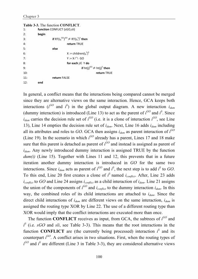
Chapter 3
100
Table 3-3. The function CONFLICT. 1: function CONFLICT (sGO,sli)
2: begin
3: if RT(i0GO)GO RT(i0
li)li then
4: return TRUE
5: else
6: X := children(i0li)li
7: Y := X GO
8: for each jY do
9: if ht(j)GO ht(j)
li then
10: return TRUE
11: return FALSE
12: end
In general, a conflict means that the interactions being compared cannot be merged since they are alternative views on the same interaction. Hence, GCA keeps both interactions (iGO and ili) in the global output diagram. A new interaction idum (dummy interaction) is introduced (Line 13) to act as the parent of iGO and ili. Since idum carries the decision rule set of iGO (i.e. it is a clone of interaction iGO, see Line 13), Line 14 empties the decision rule set of idum. Next, Line 16 adds idum including all its attributes and roles to GO. GCA then assigns idum as parent interaction of iGO (Line 19). In the scenario in which iGO already has a parent, Lines 17 and 18 make sure that this parent is detached as parent of iGO and instead is assigned as parent of idum. Any newly introduced dummy interaction is assigned TRUE by the function dum(i) (Line 15). Together with Lines 11 and 12, this prevents that in a future iteration another dummy interaction is introduced in GO for the same two interactions. Since idum acts as parent of iGO and ili, the next step is to add ili to GO. To this end, Line 20 first creates a clone of ili named iconflict. After, Line 23 adds iconflict to GO and Line 24 assigns iconflict as a child interaction of idum. Line 21 assigns the union of the components of iGO and iconflict to the dummy interaction idum. In this way, the combined roles of its child interactions are attached to idum. Since the direct child interactions of idum are different views on the same interaction, idum is assigned the routing type XOR by Line 22. The use of a different routing type than XOR would imply that the conflict interactions are executed more than once.
The function CONFLICT receives as input, from GCA, the subtrees of iGO and ili (i.e. sGO and sli, see Table 3-3). This means that the root interactions in the function CONFLICT are (the currently being processed) interaction ili and its counterpart iGO. A conflict arises in two situations. First, when the routing types of iGO and ili are different (Line 3 in Table 3-3), they are considered alternative views

An algorithm to integrate local interaction diagrams in human collaboration processes
101
on the same interaction. In this case, the CONFLICT function returns TRUE (Line 4 in Table 3-3). This is the first conflict situation. Second, when the routing types of iGO and ili are not different, the CONFLICT function builds a set X that contains all child interactions of i0
li (Line 6 in Table 3-3), and builds a set Y that contains all interactions that are members of both X and the set of interactions in sGO (Line 7 in Table 3-3). For all the interactions in the set Y, the CONFLICT function then tests whether these interactions occur on the same level (i.e. height) in sGO and sli. In other words, the function checks whether the children of i0
li have counterparts in sGO that occur on another level. If there are no such counterparts, there is no conflict and the function returns FALSE (Line 11 in Table 3-3). However, if there are such counterparts (Line 9 in Table 3-3) then i0
GO and i0li are considered
alternative views on the same interaction and the function returns TRUE (Line 10 in Table 3-3). The latter forms the second conflict situation.
Figure 3-10 shows a generic example in which the interactions AGO and Ali are in conflict because they have different routing types (i.e. the first conflict situation). A new (dummy) interaction with the same label and the routing type XOR is introduced in GOnew to act as the parent of AGO and Ali.

Chapter 3
102
Figure 3-10. A generic example of a Global Input diagram (GOold), a local input diagram (li), and a Global Output diagram (GOnew). The example illustrates the case in which Ali generates a conflict because a counterpart AGO exists with a different routing type.
Figure 3-11 depicts a generic example of the second conflict situation. In this specific example, interactions AGO and Ali are in conflict because the parent interaction Ali has a child Dli with a counterpart DGO that exists in the subtree of AGO on a different level. Therefore, a dummy interaction A with routing type XOR is added to GOnew.
A SE
Q
C
GO
old
GO
new
A
SE
Q
C
li
XO
Rd
A
XO
Rd
A
DC
D
A
XO
R
B
BC

An algorithm to integrate local interaction diagrams in human collaboration processes
103
Figure 3-11. A generic example of a Global Input diagram (GOold), a local input diagram (li), and a Global Output diagram (GOnew). The example illustrates the case in which Ali generates a conflict because it has a child interaction that occurs on a different level in the subtree of its counterpart AGO .

Chapter 3
104
Case 3: Interaction ili exists in the same segment or subtree of GO, and there is no conflict situation (Line 25) From here, any line numbers refer to Table 3-2 again. If ili exists in the same segment of GO but there is no conflict, the statement in Line 26 is executed. In this case, the components of iGO and ili are merged so that their roles and attributes are properly integrated. Figure 3-9 includes an example of this case. In Figure 3-9, parent interaction Ali has a child interaction Cli with a counterpart CGO in the subtree AGO. However, in this case there is no conflict between AGO and Ali because CGO and Cli occur on the same level in GOold and li. Thus, in this case, it is unnecessary to introduce a dummy interaction and keep both AGO and Ali in the output diagram.
3.5. Application of the Global Construction Algorithm
This section applies GCA to the example HCP described in Section 3.3 and shows the output global IS diagram. The retailer agent in the supply chain can run GCA with the different local IS diagrams it has created based on the available product-centric data (as shown in Figure 3-4, Figure 3-5, and Figure 3-6) as input. Figure 3-12 shows the output diagram. This global IS diagram shows the example HCP starting from the supplier, until the product reaches the customer, and afterwards, when optionally a product (i.e. PC) is returned by the customer for repair by the manufacturer. Despite its simplicity, the example demonstrates several important features of GCA.
First, the example shows how complementary views on an interaction are integrated when a given interaction appears in the local diagram li under consideration but does not appear in the global diagram GO. This reflects the first case in GCA. An example of such an interaction is the Assemble PCs interaction from the manufacturer diagram (see Figure 3-5), which does not appear in the retailer diagram (see Figure 3-4). A clone of this interaction is created, the clone is added to GO, and connected to the same parent in GO (see Figure 3-12).

An algorithm to integrate local interaction diagrams in human collaboration processes
105
Figure 3-12. The output of the global construction algorithm for the retailer agent in the example HCP.

Chapter 3
106
Second, the example shows how GCA deals with a conflict situation, that is, the second case in the algorithm. In the example, the retailer diagram (Figure 3-4) and the customer diagram (Figure 3-6) both include the Retailer-Customer interaction. The Ship PCs to Customer interaction, which is a child of the Retailer-Customer interaction in the customer diagram, also exists on a different level in the subtree of the Retailer-Customer interaction in the retailer diagram. Because of this, the function CONFLICT returns TRUE since the two Retailer-Customer interactions are considered alternative views on the same interaction. GCA keeps both views in the output diagram, and adds a new (dummy) parent interaction for both views. In this way, the ordering constraints of both views are preserved. Since both views are alternative descriptions of the same interaction, the new parent interaction is assigned the XOR routing type (see Figure 3-12).
Third, the example shows how GCA deals with the third case. For instance, when the root interactions in the retailer and manufacturer diagrams are being compared, a conflict does not arise. These interactions have similar routing types and the children of the Deliver PCs interaction in the manufacturer diagram do not occur on a different level in the retailer diagram. Thus, the CONFLICT function returns FALSE and GCA executes the statement in Line 26 (see Table 3-2). This statement integrates the attributes and roles of both interactions. This includes the decision rule sets of both interactions, which explains the SEQd routing type of the Deliver PCs-interaction in the global output diagram.
3.6. Discussion
In a HCP, typically, no agent has a complete view of all the interactions that occur in the process. Each agent has its own local situated view of the process. This view can be made explicit in a local IS diagram. To obtain a global view of the HCP, the local IS diagrams can be integrated using GCA. The local IS diagrams can be build based on product-centric data like in the example HCP. Here, the output global IS diagram provides the retailer agent with an end-to-end overview of the interactions in the product-centric supply chain.
For other HCPs, which are performed in business settings where no product-centric data is available, the value of GCA is its ability to integrate a set of local IS diagrams, owned by different agents. More specifically, a modeller can capture and model the local (i.e. restricted and incomplete) interaction views of the process participants (read: agents) in local IS diagrams. These local IS diagrams are created separately (and concurrently when multiple modellers are involved) for each agent.

An algorithm to integrate local interaction diagrams in human collaboration processes
107
Next, GCA can be used to integrate the local IS diagrams into a global IS diagram. In this way, the tacit domain knowledge of agents can be formalized in local diagrams and be used to build a global diagram. Taking into account the local interaction views of the agents has the potential to minimize the gap between the actual HCP and the modelled HCP. The global IS diagram makes the interactions in the HCP under study explicit, and amenable to proper analysis and improvement.
In a process execution environment, the role of the global IS diagram could be to enact and/or monitor the execution of the interactions in a given HCP. The diagram could serve as a coordination structure for the activities executed by the distributed agents to perform the interactions, and hereby improve process interoperability and alignment. For this, the agents need to adopt a multi-agent system in which the global IS diagram can reside. The realization of such a multi-agent system is part of future research. An interesting research direction is the use of GCA at process execution time. During HCP execution, it should be possible for agents to initiate interactions that are not part of the IS diagram to ensure process flexibility in highly dynamic contexts. The algorithm can be used at runtime to make sure that local changes are reflected in the (global) IS diagram. In this way, on-the-fly structural modification of the IS diagram can be realized.
GCA can be improved by enhancing the CONFLICT function. First, an enhanced version of the CONFLICT function could, in some cases, return FALSE even if two interactions with identical labels have different routing types. For instance, the PAR routing type is quite weak in the sense that it allows interactions to be executed at the same time or in an arbitrary order. Therefore, it could be possible to merge two interactions with identical labels with routing types PAR and SEQ. Second, the function should, in some cases, be able to merge alternative views with identically labelled interactions occurring on different levels (i.e. the second conflict situation in GCA). Currently, the Retailer-Customer interactions in the retailer diagram (Figure 3-4) and the customer diagram (Figure 3-6) are considered alternative views because a descendant of these interactions (i.e. the Ship PCs to Customer interaction) appears on a different level in both diagrams. Although it is likely that both diagrams are concerned with the same Retailer-Customer interaction, it is also possible that for instance the shipment in the customer diagram refers to a secondary shipment. In this case, the Retailer-Customer interactions are different interactions. The direction chosen with GCA is to represent the views of all the agents so that no information is lost, even though

Chapter 3
108
this can lead to redundant interactions in the global output diagram. Therefore, the output diagram in Figure 3-12 shows both Retailer-Customer interactions. In line with the general goal of GCA to create a minimal interaction representation, future research intends to investigate ways to minimize redundancy in the output diagram. Related to this, a possible future enhancement to GCA would be a pruning feature, which compresses the global output diagram by removing redundant interactions. Besides redundancy that can result from alternative views, redundancy can also occur when an interaction has the same routing type as its parent interaction. Often, such an interaction can be deleted and its child interactions can be directly connected to its parent interaction.
3.7. Conclusions
In product-centric supply chains, coordination and control efforts are aimed at individual products. In these supply chains, product owners store product-centric data in a database that is associated to each product individual. When this database is made accessible to partners (e.g. via a product interface), product visibility is achieved in the supply chain.
This chapter presents an example HCP of the interactions between partners in a simplified product-centric supply chain. The purpose of the example is threefold. First, it shows how a partner can use product-centric data to identify its own interactions and the interactions of other partners in the supply chain. Second, it shows how to formalize the identified interactions in local interaction diagrams for each partner. Finally, it shows how a novel algorithm is used to automatically integrate the local interaction diagrams in a global interaction diagram. The focus is on the exemplification of the formal components and workings of the algorithm. The goal of the algorithm is to build a minimal global interaction diagram where the interactions from the local interaction diagrams are merged when there is no conflict. A conflict indicates the existence of alternative local views on the same interaction. The interaction diagrams are visualized with an interaction-centric business process modelling language named TALL. The global interaction diagram increases process visibility, and benefits process alignment and operability in the HCP under study.