upgrade and operate the accelerator test facility
TRANSCRIPT

Book 1
Brookhaven national laBoratory
Upgrade and operate the
accelerator test FacilityProposal to the U.S. Department of energy office of high energy Physics

Brookhaven National Laboratory | Accelerator Test Facility Upgrade and Operate the ATF
Page | i
Table of Contents Table of Contents ............................................................................................................................. i Executive Summary ........................................................................................................................ 1
1.0 Introduction ......................................................................................................................... 3
2.0 The Accelerator Test Facility Upgrade Proposal ................................................................ 8
2.1 Science Motivation ........................................................................................................... 9
2.1.1 Science Opportunities Enabled by the CO2 Laser Upgrade to 100 TW ................. 10
2.1.2 Outlook for high luminosity LWFA ....................................................................... 14
2.1.3 Science Enabled by the Electron Beam Energy Upgrade to 500 MeV ................... 20
2.1.4 The Overall Vision of New Science at the Upgraded ATF .................................... 23
2.1.5 Efficiency, Productivity and Turn-over Time ......................................................... 27
2.2 The ATF Upgrade Building ........................................................................................... 27
2.3 Electron Beam Lines Design – Stage I........................................................................... 30
2.4 CO2 Laser Power Upgrade ............................................................................................. 34
2.5 Electron Beam Lines Design - Stage II .......................................................................... 41
2.6 The ATF as an Office of Science User Facility ............................................................. 45
2.7 Details of the ATF Relocation to Building 912 ............................................................. 52
2.7.1 Proposed ATF Transition and Systems Acquisition Strategy................................. 53
2.7.2 General ATF Design and Safety Considerations .................................................... 54
2.7.3 Structural Elements and Environmental Considerations for the ATF Beam Lines 54
2.7.4 Beam line Component Alignment and Control ...................................................... 55
3.0 Future Option for the ATF Upgrade: A Superconducting RF Energy Recovery Linac ... 58
3.1 Science Motivation for a Terahertz (THz) Source ......................................................... 58
3.2 Detailed Description of the ERL .................................................................................... 60
Appendix A: User Facility and Educational Aspects ................................................................. A-1
Appendix B: The ATF Present and Near Future ........................................................................ B-1
Appendix C: The ATF Users’ Program Scientific Achievements .............................................. C-1
References ........................................................................................................................................ I

Brookhaven National Laboratory | Accelerator Test Facility Upgrade and Operate the ATF
Page | 1
Executive Summary The Accelerator Test Facility (ATF) at Brookhaven National Laboratory (BNL) has been serving the Department of Energy (DOE) Accelerator Stewardship mission for over two decades. In its operations as a user facility it serves a large community from Academia, National Laboratories, Small Business and International Users. It provides unique facilities, such as high-brightness electron beams and high-power lasers synchronized to the electron beams in three beam lines. The science and technology engendered at the ATF are documented by numerous publications that are frequently cited. The ATF serves as a training ground for post-docs and graduate students in accelerator science. In this document, we propose to upgrade the ATF in several ways to open up new science opportunities and increase its productivity and service to its large user community. We also propose to DOE to grant the ATF the status of a formal Office of Science User Facility.
The Accelerator Test Facility (ATF) was established over a quarter of a century ago by two visionaries of accelerator science, Bob Palmer and Claudio Pellegrini. For more than two decades it has served national and international accelerator scientists, through a proposal-driven, program committee reviewed process that makes beams available to a broad community of users from Academia, U.S. National Laboratories, Accelerator Facilities and Small Businesses (see Appendices A and C of this proposal). The ATF offers the state-of-the-art tools that are required by its user community, including sources of high-brightness electron beams and synchronized high-power laser beams (see Appendix B of this proposal). While making these available for accelerator science Research and Development (R&D), the ATF continuously upgrades, reinvents and revamps these tools.
The accelerator science carried out at the ATF continues to yield a distinguished record of frequently cited publications in refereed, high impact journals (see Appendix A of this proposal). This attests to the ATF’s role as a recognized world leader in accelerator science and technology. The ground-breaking tools and techniques developed by its users are transforming other accelerator-based User Facilities.
In addition, the ATF has a distinguished record as a training ground for educating graduate and postgraduate scientists. Despite its modest size, the ATF meets the educational and training needs of about 14% of the total number of U.S. accelerator-science students. The educational impact of the ATF is amplified by its seamless integration into the activities of the Center for Accelerator Science and Education (CASE) at the nearby Stony Brook University (SBU). CASE is co-sponsored by SBU and BNL.
The ATF Facility has Broad Impact for American Science “The BNL ATF is an invaluable resource for the community of sciences dependent on accelerators for their work and for beam science itself. The ATF provides a platform for experiments in the science and technology of beams and accelerators, different from other test facilities. This distinction is achieved through the extreme flexibility of the accelerator itself and its program and of the end stations where the well characterized beams are used. In addition and of great importance is the flexibility and technical expertise of the personnel who make the ATF operate efficiently and are more than willing and able to serve non expert users in getting difficult parts of their experiments done successfully. This facility–including both physical and personnel infrastructure–supports beam science and accelerator technology that will be reflected in new potential for the science community dependent on accelerators as well as providing new knowledge of beam science and technology. Support of these functions is essential for American science.” Maury Tigner, Cornell University

Brookhaven National Laboratory | Accelerator Test Facility Upgrade and Operate the ATF
Page | 2
The ATF continues to foster fundamental accelerator science and technology development of relevance to numerous fields; from High Energy Physics (HEP), to Basic Energy Science (BES), and Nuclear Physics (NP), as well as broad accelerator concepts that defy such divisions. It has been a vigilant steward of accelerator science from its inception, always seizing diverse opportunities to push back the frontiers of accelerator science and technology.
The objective of this proposal is to enable a vision of cutting-edge science for the next decade and beyond to improve productivity and service, all aimed at the support of the large community of ATF users.
Proposal Components The ATF comprises three principal components: 1) electron accelerator; 2) synchronized suit of lasers; and 3) experiment halls and beam lines. The upgrade is aimed at making vast improvements in the capabilities of all three components. A common enabler is the relocation of the facility to the former Alternating Gradient Synchrotron (AGS) experimental area in BNL Building 912, where three times its present space will be available. The upgrade, described in detail in Section 2, then will achieve:
1. Upgrade of the ATF’s synchronized CO2 laser from the current 1 TW to 100 TW, funded by a BNL Program Development grant but enabled by this upgrade.
2. Improvement of the ATF’s electron beam quality and stability, through a new state-of-the-art photocathode RF gun, 10 micrometers precision alignment and new, highly stable support system of the beam line components.
3. Increasing the maximum achievable electron energy at the ATF, from 80 to 500 MeV by adding linac sections and another dedicated experiment hall. The increased energy would secure a smaller beam, a feature that is very important for ultra-high-gradient structure-based accelerator R&D, beam plasma R&D, higher energy beam produced radiation such as Compton-generated gamma rays, or Free Electron Lasers. This electron beam upgrade is a part of a second stage within the ATF upgrade program.
4. Nearly doubling the annual scientific throughput while halving the turn-around time between experiments, mostly achieved by providing independent experiment halls. This reduction in turn-around time is particularly critical for industrial users and graduate students.
5. Improved space and access for large, complex experimental setups.
6. It is also proposed that the DOE grant the ATF the formal status of an Office of Science User Facility.
7. Potential addition of a 300 mA average current superconducting RF Energy recovery Linac (no funding requested in this proposal). The addition of this ERL, built under a separately funded program, will then achieve R&D on high beam intensity and serve for various user applications, such as high-repetition rate Terahertz (THz) and Compton radiation.

Brookhaven National Laboratory | Accelerator Test Facility Upgrade and Operate the ATF
Page | 3
1.0 Introduction The mission statement of the Department of Energy (DOE) Office of High Energy Physics (HEP) supports theoretical and experimental research in both elementary particle physics and fundamental accelerator science and technology. Brookhaven National Laboratory’s (BNL’s) Accelerator Test Facility has been supporting this important mission for 20+ years by providing state-of-the-art resources and expertise to accelerator science and technology scientists from Academia, Industry and the National Laboratories.
The science of accelerators and particle beams is rich and challenging, and its impact on society and other sciences is extremely broad. As we continue to design and build new accelerators that push the known technology to its limits, we must also explore revolutionary new methods of acceleration; for example using plasmas, structures, beam or laser wakefields, developing novel methods of generating useful electromagnetic radiation from beams, and much more. The Accelerator Test Facility (ATF) mission is to address this challenge by providing unique opportunities for studies of the complex properties of modern accelerators, developing new techniques of particle acceleration using lasers, beam plasma interactions and supplying beams for a variety of researchers developing applications using fundamental accelerator and laser science.
The ATF has served the objective of Accelerator Science Stewardship from its inception, even before the term was introduced. It continues to serve the High Energy Physics (HEP), Nuclear Physics (NP), and Basic Energy Sciences (BES) communities, and is indeed a multi-disciplinary Research and Development (R&D) center. It combines high-brightness electron beams, synchronized powerful laser beams, and beam lines equipped with state-of-the-art instruments with a dedicated, stable staff that has been running the facility for decades. Additional information concerning the performance of the ATF as a User Facility and its achievements in graduate education in accelerator science is provided in Appendix A of this proposal. The ATF’s current capabilities and improvement program, including the BNL Program Development funded 100 TW CO2 laser, are described in Appendix B.
The ATF has been a wellspring for numerous capabilities. For example, research carried out at the ATF was critical to the advent of X-ray Free Electron Lasers. The S-band laser photocathode RF gun that enabled the Linac Coherent Light Source (LCLS) was developed for the ATF, where its ability to generate very high-brightness electron beams was demonstrated. The first ever demonstration of Self Amplified Spontaneous Emission (SASE) in visible wavelength occurred at the ATF, as well as the first ever seeded, high gain harmonic generation laser.
The ATF is Unique Among Accelerator Facilities • High-brightness electron beams synchronized with high-
power lasers, for laser electron beam interaction experiments. • A long, distinguished history of service to users,
demonstrating a steady pool of users. • Funding from Office of High Energy Physics (OHEP) and
the office of Basic Energy Science (BES) for over 2 decades. • A strong record of high impact publications and citations. • A strong, steady record of education of students at all levels. • A terawatt CO2 laser with plasma ion acceleration
performance, with a funded upgrade to 100 TW. • A small, highly experienced team of 12 people, viz.,
scientists, engineers, and technicians dedicated to serving its users.
With optional additions, the ATF will also encompass two more unique capacities: • CW operation of SRF linac, with variable repetition rate up
to 700 MHz. • Highest average power – 1 MW of power from the SRF gun,
20 MW in the ERL.

Brookhaven National Laboratory | Accelerator Test Facility Upgrade and Operate the ATF
Page | 4
The ATF hosted VISA, the proof-of-principle strong focusing Free Electron Laser (FEL) that lased to saturation at the visible light regime. The first ever staged laser accelerator achieved a narrow energy spread at the ATF, in what was then a novelty for laser accelerators. More information on the accelerator science achievement by ATF Users and staff over the past two decades is provided in Appendix C.
The ATF program is situated at Brookhaven National Laboratory (BNL), which hosts a suite of forefront accelerators, from the nation’s only hadron collider to the latest synchrotron light source. BNL maintains active programs in High Energy Physics (HEP), Nuclear Physics (NP), and Basic Energy Sources (BES), and has a global reputation for advancing the frontiers of accelerator technology and accelerator-based science. BNL makes the ATF facilities and expertise available for the support of users from academia, industry, medicine, national security and education.
User Facilities and Support Much of the U.S. work in accelerator science and engineering occurs in National Laboratories, but Universities and small businesses also play a unique and important role. How can all these diverse groups undertake cohesive experimental research to explore bold new ideas, test new techniques, and prove theoretical models? The answer is clear: In User Facilities (the mainstay of many sciences), and by hosting a free service to the users, they deter waste and duplication of efforts. Invaluably, they enable investigators with a small budget to carry out their experimental work using the most advanced accelerators and beams, supported by expert staff. The ATF pioneered the concept of a user facility for accelerator science over a quarter of a century ago. Experiments are conducted through a proposal-driven, Program Committee reviewed process.
ATF user’s participate in an organization called the RHIC and AGS Users Group. The ATF employs the services of the central BNL Guest, User, and Visitor Center (GUV), which offers services for all User Facilities at BNL, including the Relativistic Heavy Ion Collider (RHIC), the Center for Functional Nanomaterials (CFN), the National Synchrotron Light Source (NSLS), the ATF, the NASA Space Research Laboratory, the Tandem Van de Graaff, and the New York Blue supercomputer.
The Center for Accelerator Science and Education An important element in the ATF program is graduate education. Throughout the lifetime of the facility, 35 students from 17 universities have received graduate degrees based on their work
The ATF Facility Supports the DOE HEP Mission “Currently we are working on several projects as users at the ATF. These have applications for X-ray free electron lasers, light sources and future linear colliders. Most of these challenging R&D efforts will benefit greatly from an upgraded facility; in particular the energy upgrade will allow us to work with smaller dielectric wakefield structures yielding higher gradients. We are very enthusiastic about the proposed ATF-2…The proposed upgrade is timely and well thought through, building on the strengths that the ATF is known for: operational flexibility and synergy of high-brightness beam with a state of the art high-power laser program. I particularly appreciate the switchyard of beam lines that will allow multiple users to operate in parallel, running in one experimental hall while setting up another experiment in the other. Not only will this increase the productivity of the facility, it will enhance cross-collaborations of different groups at the ATF, already a creative environment for the advanced accelerator concepts community.” Sergey Antipov, PhD, Director, Radiation Sources Department, Euclid Techlabs LLC

Brookhaven National Laboratory | Accelerator Test Facility Upgrade and Operate the ATF
Page | 5
accomplished at the ATF. Currently, 22 students from 7 universities are progressing towards achieving their Ph.D. degrees.
The ATF participates in the activities of the Center for Accelerator Science and Education (CASE) that is a joint venture of BNL and Stony Brook University (SBU). CASE pursues cutting-edge accelerator science and R&D, expanding and regularizing some of the past ATF initiatives, and encompassing broader aspects of accelerator science and education beyond just those topics traditionally treated by adjunct arrangements. CASE trains the next-generation of accelerator scientists, graduate students and post-doctoral fellows, through courses, laboratory assignments, and experiments on accelerators. Opportunities for undergraduate students play a significant goal in attracting them into the graduate program, by introducing them to courses on accelerators, laboratory work, and summer research opportunities at BNL. Both the accelerator research arm of CASE, and the ATF are organizationally located within the Accelerator R&D Division of the Collider-Accelerator Department.
The Collider-Accelerator Department As the ATF is organizationally located in the Accelerator R&D Division of the Collider-Accelerator Department (C-AD) at BNL, the ATF benefits from the expertise of many accelerator scientists, engineers and technicians in a department over 400 persons strong. Further, a broad study of potential C-AD upgrades to improve operational efficiency lead directly to some of the ideas documented in this proposal. Beginning with key mission critical buildings, additional studies are being performed to refine the needs and develop time-phased implementation plans. The ATF profits from this type of planning and stewardship while leveraging the substantial infrastructure, utility systems, and human resources available within C-AD. Indeed, there is no substitute for the proximity of skilled, trained technical support. BNL also supports the ATF in other ways, for example through Information Technology and machine shop facilities.
The ATF Upgrade Proposal In this proposal we set a vision for the ATF’s next ten to twenty years. Starting with the ATF’s unique strength, a high precision electron beam, synchronized with high-power CO2 laser, we plan to dramatically increase the science reach of the facility by the following: 1). Increase the laser power 100 fold, from 1 TW to 100 TW; 2). improve the electron beam emittance and beam stability; 3). increase the maximum energy of the electron beam from 80 MeV to 500 MeV; 4). cut the time required to run a typical experiment by nearly a factor of two; and 5). increase the space available to user experiments and key facility elements by about a factor of 3. A key ingredient common to these improvements is the relocation of the ATF to another building at BNL, the former AGS experimental hall. The relocation will involve minimal interruption in services to users.
We also propose to the DOE that the ATF becomes a formal Office of Science User Facility.
A future option, enabled by the relocation, described briefly in this proposal but not part of this proposal is the addition of a superconducting Energy Recovery Linac (ERL) to the set of ATF tools. This ERL is being constructed in the same future building of the ATF under another program; thus, no construction funds will be required to exercise this option.

Brookhaven National Laboratory | Accelerator Test Facility Upgrade and Operate the ATF
Page | 6
Book 1 Book 1 proposes ATF upgrades and operations, and provides much information about the ATF users program and its capabilities.
Section 2 of Book 1 describes in detail the ATF upgrade proposal, which has two distinct stages: The first stage is the upgrade of the electron beam performance, implementation of the 100 TW laser and doubling of productivity associated with the move of the ATF to its new location. The second stage is the electron beam energy upgrade to 500 MeV.
The organization of this section includes the following key sections:
2.1 Science Motivation 2.2 The ATF Upgrade Building 2.3 Electron Beam Lines Design – Stage I 2.4 CO2 Laser Power Upgrade 2.5 Electron Beam Lines Design - Stage II 2.6 The ATF as an Office of Science User Facility 2.7 Details of the ATF Relocation to Building 912
Section 3 describes an option for a future ATF upgrade that would be enabled by adoption of the present proposal. This upgrade will add a superconducting Energy Recovery Linac (ERL) to the facility. Adding an ERL, would enable R&D on high-intensity electron beams and for various user applications, such as high-repetition rate Terahertz (THz) radiation, Compton generated X-rays and high-power Free Electron Lasers.
Appendix A describes the effectiveness of the ATF as a unique national user facility for beam physics experiments, which also provides training for the next-generation of accelerator scientists in cutting-edge tests of advanced accelerator concepts. An important element in the ATF's program is its post-doctoral and graduate education in accelerator, beam, and laser physics. During the lifetime of the ATF, 35 students from 17 universities received a graduate degree based on their work done at the ATF, and 22 students from 7 universities currently are progressing towards achieving their Ph.D. degrees.
Appendix B describes the ATF at present, operating for two decades as a state-of-the-art user facility following the Office of Science mission to “support theoretical and experimental research in both elementary particle physics and fundamental accelerator science and technology”. The ATF continues to provide unique opportunities to study the complex properties of modern accelerators, new techniques of particle acceleration using lasers, beam plasma interactions, and much more. It is an indispensable tool supplying beams for a variety of researchers developing applications using fundamental accelerator and laser science. Researchers from Universities at home and abroad, from the Department of Energy’s (DOE’s) National Laboratories, and from Small Businesses carry out a large variety research programs. These
The ATF is a Unique National User Facility “ATF provides a critical support by offering access to the beam time, equipment, and, importantly, the cutting-edge expertise in laser and accelerator physics available at the facility. The planned facility upgrade would much further enhance such capabilities, and offer users a multitude of new and exciting opportunities…As the proposed upgrade will reduce the turnover time for the projects, it would be of great benefit to all of the ATF present and future users, but especially it is great for the small business community, the success of which, as well as very survival often depends on the ability to dynamically respond to the ever-changing market conditions with new offerings of products and services. ”Alex Murokh, Chief Technology Officer, RadiaBeam Technologies, LLC

Brookhaven National Laboratory | Accelerator Test Facility Upgrade and Operate the ATF
Page | 7
users choose the ATF due to the ready availability of the accelerator, lasers, control and diagnostic equipment, and our trained support personnel: the accelerator and laser operators.
Appendix C gives a history of completed experiments and prominent scientific achievements by ATF users. Capitalizing on the successes of the first-generation experiments, users developed and executed more complex second-generation experiments. Consequently, each new experiment has benefitted greatly from the accumulated knowledge and capabilities gained over more than 20 years of the ATF operations. In the last three years, operational statistics showed that 14% of beam time was used by research groups from small private companies, and more than 43% by experimenters coming from Universities.
Book 2 Under a separate cover, Book 2 provides supporting material in the Project Execution Plan, detailed Work Breakdown Structure and Schedule, and a bottom-up cost estimate, including contingencies and overheads. Also included are letters of support from the ATF community, attesting to the statements made in this proposal about the value and performance of the ATF over its long history.
New user proposals are provided in Book 2, over and above the current 17 approved and active experiments and feasibility studies. The new proposals are:
The Monoenergetic Ion Acceleration Using CO2 Laser-Driven Collisionless Shocks in a Gaseous Plasma project would continue the exploration of the key physics issues associated with the acceleration of monoenergetic ions using collisionless shock waves through experiments, theory, and simulation. These shocks waves will be excited in a gas jet plasma using the 100 TW CO2 laser at the ATF.
The Hadron Therapy using Compact Laser Driven Ion Accelerators project would use the laser facility driven by the CO2 laser to do preliminary R&D on a compact and inexpensive hadron therapy accelerator.
Experimental Study of Electron Beam Micro Bunching Dynamics and Shot Noise Suppression Effect in High Energy e-beams project takes advantage of the reconfigured ATF facility to conduct new research on collective interaction noise control and noise suppression wavelengths.
Particle Acceleration by Amplified Wake project builds upon the particle acceleration by stimulated emission (PASER) process that was first demonstrated at the ATF. The proposed upgrade of the ATF electron beam along with its existing CO2 laser, which is needed to drive an inverse free electron laser (IFEL) to create the microbunches, will be an ideal environment to pursue the Particle Acceleration by Amplified Wake (PAAW) experiment.
A letter of intent was also submitted. The Inverse Free Electron Laser at >1 GeV/m experiment would use the 100 TW laser to accelerate a 50 MeV electron beam to about 1.2 GeV in a length of one meter.

Brookhaven National Laboratory | Accelerator Test Facility Upgrade and Operate the ATF
Page | 8
2.0 The Accelerator Test Facility Upgrade Proposal In this proposal we set a vision for the Accelerator Test Facility’s (ATF’s) next decade and beyond. We aim to extend and continue our tradition of excellence, provide greater service to the ATF users, and provide new capabilities for the demanding requirements of future accelerator science. The ATF has two decades of history serving the accelerator and radiation science communities, and has forged a strong synergistic partnership between the facility and its users such that the ATF has emerged as the standard bearer for User Facilities in the accelerator science community. This experience is unrivaled as it translates to institutional and collaborative Research and Development (R&D) results for the Department of Energy’s (DOE’s) mission. Specifically, we propose to improve the electron beam quality, stability and energy at the ATF through a new electron gun and laser system, through state-of-the-art engineered beam lines featuring laser tracker alignment and reduced temperature induced motion, and by adding linac sections and RF systems. We propose to upgrade the CO2 laser beam power to 100 TW and provide a shielded hall for laser acceleration experiments that will reach hundreds of MeV protons and GeV electrons. We further propose to reduce the time to carry out a typical user experiment by nearly a factor of two, to improve utilization of assets and increase science productivity. The common denominator of these upgrade elements is the move of the ATF to a new and spacious location, featuring multiple experiment halls, and space for the 100 TW CO2 laser and its beam lines. Finally, we propose to the DOE that the ATF becomes a formal Office of Science User Facility.
After 20 years of Department of Energy investment, it is important to upgrade and expand the Accelerator Test Facility (ATF) facilities to meet the increasing demand for complex and frontier experiments and the growing demand for facility access. With new tools, new science is enabled.
In the vision guiding this proposal, we will provide new and unique laser and electron beam capabilities, to carry out the ATF’s traditional and unique role of providing precision electron beams in synchronism with high-power laser beams. This vision also proposes to the Department of Energy (DOE) that the ATF becomes a formal Office of Science User Facility, with dramatically increased space for experiments and near doubling of the scientific throughput of the facility.
The one feature unifying the upgrade in electron and laser beams, as well as the improvement in the accessibility and turn-around time for the users is the relocation of the ATF to a new building. Hence, new exciting and unique capabilities will be added. New space will allow accelerator Research and Development (R&D) oriented experimental programs to be undertaken in safe, reliable, and time-cost efficient manner.
The proposed upgrade consists of implementing a power increase of the ATF’s CO2 laser from 1 TW to 100 TW peak power (with the laser power upgrade being part of a current BNL Program
The ATF Program Advisory Committee Review of the Upgrade Proposal
“The proposed upgrade of the ATF will enable a vision for the future where state-of-the-art high precision electron beam experiments will be provided to users together with an ultra-high peak power short pulse CO2 laser, which is unique in the world. We believe that this upgrade will be crucial for the future of accelerator science and US preeminence in this important area of science. Given that the current available laboratory space is utilized at full capacity and does not allow further expansion and has constrained the efficiency with which experiments can be conducted, moving ATF to a new location is deemed essential.”

Brookhaven National Laboratory | Accelerator Test Facility Upgrade and Operate the ATF
Page | 9
Development project), within the expansive space made available through the relocation of the facility. The electron beam quality will be enriched through a new RF gun with improved emittance, and a new photocathode laser system. It will also be improved through the use of a high precision and high stability supports and alignment systems for the accelerator components. The energy upgrade to 500 MeV will provide several additional enhancements. The new gun and laser will simplify the transition of the ATF to its new location and reduce the associated down-time.
The dramatic improvement in both CO2 laser beam and electron beam will open up new science capabilities for each beam by itself and by the unique hallmark of the ATF, the synchronized use of both beams in the same experiment.
The greatly enhanced service to the users is enabled by the new location, with independent experiment halls that nearly double the throughput of accelerator science deliverables, shorter time from idea to paper and plentiful space, and easy access for complex experimental apparatus.
Finally, the status of the ATF as a user facility for accelerator science will be formalized according to the new Department of Energy (DOE) Office of Science guidelines.
Our vision is: after the proposed upgrade, that the ATF will have an unparalleled accelerator science reach and will be further established as the world’s leading facility for advanced accelerator research.
2.1 Science Motivation The science motivation for the proposed upgrade of the ATF is based on superior laser and electron beam performance, as well as user experiment turn-around time. The new, vastly extended science reach of the upgraded ATF is created by moving the ATF to bldg. 912 with its unique infrastructure and abundance of space including rooms for the new expanded 100 TW CO2 laser system, the electron beam energy upgrade, and space for the multiple independent experiment halls. Equally critical is the availability of radiation shielded space for conducting experiments with ultra-high-power laser beams: Up to 200 MeV proton beam energies can be expected after focusing the 100 TW CO2 laser beam onto a hydrogen jet. This unique high-power laser aligns with the goals of two topical mid-term high impact and focused efforts of the Department of Energy’s (DOE’s) Office of High Energy Physics (OHEP), namely to improve delivery of particle beams, and to ensure their control and stability for potential cancer therapy facilities. High-power laser development addresses the needs of a broad accelerator community.
The ATF Upgrade and the Stewardship Program “Strategies: Improve access to national laboratory accelerator facilities…Immediately augment existing programs to provide opportunities for industrial users at DOE facilities by increasing support staff and funding for beam test facilities…In the mid-term (2–5 years), identify a few topical areas with high impact for focused work. Selected areas are: (1) improved particle beam delivery and control for cancer therapy facilities; and (2) laser development addressing the needs of the accelerator community…” J. Siegrist, on the Accelerator R&D Stewardship Program, Fermilab, November 13, 2012. The ATF provides opportunities for industrial users, as 14% of its users come from small business. Our proposal is aimed at augmenting the access for users by having a faster turn-around time for experiments and providing additional staff to support the users. Our proposal also addresses very directly the mid-term goals of DOE by the unique 100 TW laser development and by the research planned for ion beams applicable to cancer therapy.

Brookhaven National Laboratory | Accelerator Test Facility Upgrade and Operate the ATF
Page | 10
Bringing ultra high-power laser beams to the electron beam lines will enable the next-generation of laser/e-beam interaction experiments, such as Inverse Compton Scattering or Laser Wakefield Electron Acceleration. This requires using big aperture (up to 10”) laser optics enclosed into large diameter high vacuum transport lines and optical setup chambers. Extra space to accommodate high-power laser transports and setups will be provided in new expanded ATF experimental halls in bldg. 912.
2.1.1 Science Opportunities Enabled by the CO2 Laser Upgrade to 100 TW Integration of the ultra-high-power IR laser, made possible through the ATF upgrade, will provide ATF users with unique opportunities to explore wavelength scaling of strong-field physics phenomena at a laser strength parameter a0=10 and higher.
Two ATF user proposals and a letter of intent, provided in Book 2 of the ATF Upgrade Proposal, address the use of the 100 TW upgrade. These are Monoenergetic Ion Acceleration Using CO2 Laser Driven Collisionless Shocks in a Gaseous Plasma (C. Joshi), and Hadron Therapy using Compact Laser Driven Ion Accelerators (A. Drees and A. Dilmanian). These proposals underscore some of the scientific potential of this upgrade. The letter of intent is for the demonstration of an IFEL accelerator, with greater than 1 GV/m (P. Musumeci).
From its very inception, the ATF has steadfastly continued its quest to offer new opportunities for user experiments by elevating the CO2 laser’s peak power.
The diagram in Figure 2-1 represents a historical perspective of the evolution of the ATF’s laser over the last 20 years: it shows the dramatic increase in power of nearly three orders-of-magnitude that we have realized from over the lifetime of the ATF.
Figure 2-1. History of ATF user experiments enabled by our continuing upgrades of CO2 laser power.

Brookhaven National Laboratory | Accelerator Test Facility Upgrade and Operate the ATF
Page | 11
Every step up in the laser’s power enabled a new series of user experiments, as illustrated in Figure 2-1. The experiments undertaken at the ATF using the CO2 laser (past and present) are listed in the diagram, and are reviewed in Appendix B and Appendix C of this proposal. These accomplishments, in part, exploit the advantages of the long wavelength laser to carry out pioneering ATF users’ experiments.
We discuss the long wavelength benefits below, together with examples of ATF experiments that exploited them:
• Favorable scaling of accelerating structures, better electron phasing into the field o Inverse Cherenkov acceleration o STELLA (Staged Laser Accelerator) o IFEL (Inverse Free Electron Laser)
• Stronger ponderomotive effects at the same laser intensity o Ion acceleration o Nonlinear ICS (Inverse Compton Scattering)
• Tenfold more photons per Joule of laser energy o ICS
• A hundredfold lower critical plasma density o Shock wave ion acceleration
The justification for developing a new ultra-fast CO2 laser technology rests on the aforementioned arguments that have favored a Mid-IR laser for several classes of experiments throughout the ATF’s history. Similar advantages will be gained at the even higher laser powers we plan to deliver, enabled by further upgrades. Furthermore, this ultra high-power IR laser will provide ATF’s users with unique opportunities to explore wavelength scaling of strong field physics phenomena at a laser strength parameter a0=10, and wavelength λ=10 µm. Opportunities for scientific breakthroughs at the ATF include:
• Ion Acceleration to the 200 MeV level, as needed for medical applications; • Laser Wakefield Electron Acceleration where the longer wavelengths expectedly will
create a proportional improvement in the beam’s charge and emittance; • IFELs with more than 1 GeV/m acceleration gradients; • Vacuum Electron Acceleration that will acquire a new diagnostic; combining this with
Compton probing may reveal the much sought, but still elusive electron acceleration within the laser’s focus; and
• New opportunities in developing radiation sources: o Generating a continuum in high Compton harmonics in the X-ray and gamma-ray
regions. o Extending HHG super continuum in gases to 8 keV (up to the 80,000th harmonic). o Realizing intense Terahertz (THz) radiation produced by hot electrons by
focusing the laser on metal foils.

Brookhaven National Laboratory | Accelerator Test Facility Upgrade and Operate the ATF
Page | 12
A graphical illustration of the scientific opportunities anticipated from the ATF laser upgrade, at its various stages, is shown below in Figure 2-2.
Figure 2-2. Opportunities for new science outreach at different stages of the CO2 laser upgrade.
The six scientific cases discussed below, exemplify new opportunities for user experiments that will benefit from the future 100 TW CO2 laser. Three of them (Shock Wave Ion Acceleration, LWFA, and IFEL) belong to the field of advanced particle accelerators, and the other three (Inverse Compton harmonic continuum, Terahertz (THz) source, and HHG super continuum) to advanced radiation sources. We detail these applications in the following paragraphs. Proton accelerator (from 2 MeV to 200 MeV) An important argument for developing multi-terawatt CO2 laser technology is to empower research in ion acceleration, motivated by applications such as radiation therapy. The method of Laser Shock Wave Acceleration (LSWA), recently demonstrated with the CO2 laser is discussed in detail in Appendix B. It shows promise for becoming one of the leading candidates to achieve the ultimate goal of attaining 200 MeV proton beams with parameters very suitable for medical treatment. The major distinctive features of this methodology include the production of monoenergetic ion beams, and the close to linear scaling of the ion energy with the laser’s
Hadron Therapy Highlights Ion beams are attractive for hadron therapy, the treatment of cancer by ion beams, which can deposit their energy in a very localized tumor region and thus limit the damage to healthy tissue. Being able to do this with a very compact machine is the signature of laser accelerators. This opportunity is detailed further in proposals included in Book 2.

Brookhaven National Laboratory | Accelerator Test Facility Upgrade and Operate the ATF
Page | 13
intensity. The recent results and the simulations allow us to project that about 200 MeV can be met at ~1018 W/cm2 of the CO2 laser intensity, easily attainable at the 100 TW peak power. Recent simulations shown in Figure 2-3, (see this proposal, Book 2, Attachment C-1) support these arguments.
a b c Figure 2-3. Shock-wave simulations showing proton momentum distribution as a function of position in units of
plasma inverse wavenumber (a), ion spectra at different laser a0 with red corresponding to a0=10 (b), and dependence of maximum proton energy on a0 using approximate equation and simulation (c).
Even if one can produce plasma targets compatible with the 1 µm laser sources (required density ≥1021 cm-3), intensity one hundred times higher would be required to reach the same shock wave velocity. Recent findings support the notion that a collisionless shock wave, which is the ultimate source of proton beams, exists only in the course of the laser pulse. Therefore, in addition to the peak power that defines the immediate velocity of the shock wave, attaining a pulse of picosecond duration is critically important to allow the shock wave to fully penetrate a typical gas jet target of about 0.5 mm thick.
Typically, at several tens of femtoseconds, it is unlikely that ultra-fast solid state lasers could be suitable in practice for the LSWA task. This makes the forthcoming ultra-fast 100 TW CO2 laser the prime candidate for achieving this promising method of producing low energy spread, high-brightness ion beams. Please note that meaningful biological and material studies can be initiated at earlier stages with much smaller proton and ion energies as has been already demonstrated at the ATF (see E. Stolyarova, D. Stolyarov, K. Bolotin, S. Ryu, L. Liu, K. T. Rim, M. Klima, M. Hybertsen, I. Pogorelsky, I. Pavlishin, K. Kusche, J. Hone, P. Kim, H. L. Stormer, V. Yakimenko and G. Flynn, Observation of Graphene Bubbles and Effective Mass Transport under Graphene Films, Nano Lett. 9, 332–337 (2009)).
Another important application of the LSWA method could be generation of deuteron beams which are effective for generating neutrons. High-intensity, compact neutron sources are in high demand for a spectrum of applications ranging from material science to nuclear material interrogation for Homeland Security. The high efficiency of the CO2 laser energy conversion to directed ion beams implies that such source could become a candidate for a practical compact neutron generator.

Brookhaven National Laboratory | Accelerator Test Facility Upgrade and Operate the ATF
Page | 14
2.1.2 Outlook for high luminosity LWFA
Laser Wakefield Accelerators (LWFAs), wherein a high-intensity laser pulse creates a plasma wake that can accelerate electrons, have demonstrated very high acceleration gradients up to 100 GV/m. Most experiments used near infrared laser sources (λ=0.8-1 µm) that offer multi-terawatt peak powers and femtosecond pulses. Therefore, it has been noted that longer laser wavelengths have certain advantages due to the wavelength scaling in the electrons’ ponderomotive potential that is crucial in launching the collective plasma electron motion and wakes. These advantages have not been fully explored experimentally because of the lack of long wavelength multi-TW mid-IR laser sources with a pulse length sufficiently short to drive a plasma wake at a competitively high-field gradient. The parameters achievable with the ATF CO2 laser open up the possibility to perform LWFA experiments at 10 µm. In addition, the ATF users have been doing capillary-discharge experiments which demonstrated channeling of the CO2 laser light. Thus, the ATF not only possesses a viable laser driver for LWFA, but also a verified means by which to confine it over many Rayleigh lengths. The so called resonant LWFA normally requires the length of the laser pulse, τp , to be comparable to or less than half of the plasma wake’s period, 𝜋 𝜔𝑝⁄ , where 𝜔𝑝 ∝ 𝑛𝑒
1 2⁄ . At the plasma density of ne=1016 cm-3, considered close to the low limit for a meaningful high-gradient LWFA, this corresponds to τp≈0.4 ps. An amplified 2-ps CO2 laser pulse, soon to be attained with the implementation of a new Optical Parametric Amplifier (OPA) as a front-end for an upgraded ATF CO2 laser, would be still too long for optimally generating a plasma wake in the resonant LWFA. However, simulations show that even though the 2-ps duration of the laser pulse is several times longer than that for ‘‘resonant’’ LWFA, a very strong wake can still be generated. This achievement reflects the nonlinear evolution of the laser pulse upon coupling with the plasma. The laser pulse’s envelope (Figure 2-4a) becomes modulated, with the peak intensity more than 50% higher than its initial value.
a b
Figure 2-4. The normalized laser field (a), and electron plasma density (b), after 6.7 cm propagation in a plasma. (Side by side comparison would be clearer if longitudinal and radial axes would be parallel, not rotated as above).
However, a more important effect, in terms of wake generation, is the nonlinear steepening of the pulse, caused by two effects: 1). Self focusing at the peak of the laser pulse; and 2). a modulation growing near the pulse’s trailing edge. Such a modulated pulse falls into resonance with the plasma and produces a strong wake.

Brookhaven National Laboratory | Accelerator Test Facility Upgrade and Operate the ATF
Page | 15
Simulations predict a wake amplitude >1 GV/m for a 2-ps, 2.5-TW laser pulse. In addition, the wake is very regular, as illustrated in Figure 2-4b. The formation of regular wakes is one vital prerequisite for staging LWFA devices in series, a feature that will be important eventually for developing practical accelerators based upon LWFA. We plan to probe the accelerating gradient with a femtosecond electron bunch from the ATF linac. Although not record-breaking in comparison with Ti:sapphire driven LWFA, the ATF experiment should demonstrate good acceleration gradients exceeding those of conventional RF accelerators by an order-of- magnitude, even at relatively low 2.5 TW CO2 laser power. This experiment will become a test-bed for exploring seed bunch phasing into the wake, and beam loading effects.
The LWFA experiment at the ATF will progress together with the laser power upgrade, finally reaching the condition for the bubble LWFA regime at the following CO2 laser parameters:
Laser peak power P = 100 TW Laser pulse duration τ = 500 fs Laser pulse energy EL = 50 J
We have taken the following considerations into account for attaining the bubble regime:
The laser power should exceed the threshold value for the blow-out regime [1]: 2 2
0( ) ( [fs] / [μm]) 30GWbubble relP P P ω τ τ λ> ≅ ≅ × , (1)
where, 2 5 20/ 8.5GW, 2 / 1.9 [fs] / [μm]relP m c e cω τ π τ λ τ λ= ≈ = ≅ .
For these laser parameters above, 75TWbubbleP ≅ , is just slightly below the laser’s power at the laser pulse duration τ = 500 fs. There are additional key conditions for the bubble regime:
The radius of the laser pulse, R, should scale as 1/ 2
0 0cr
e
nk R an
≅
, (2)
and its duration should be short compared with its radial size
/R cτ ≤ , 𝜏 ≤ 𝜆2𝜋𝑐
�𝑛𝑐𝑟𝑛𝑒𝑎0�
1 2⁄. (3)
These conditions determine the range of plasma density and intensity, that for 𝑎0 = 8 gives
𝑛𝑒 ≅ 5 × 10¹⁵𝑐𝑚−3
𝑅 ≅ 75𝜇𝑚, and the length of acceleration
𝐿𝑎𝑐𝑐 ≅ 0.7 𝑐𝜏𝜆𝑍𝑅 ≈ 3 𝑐𝑚. (4)
Brookhaven National Laboratory | Accelerator Test Facility Upgrade and Operate the ATF
Page | 16
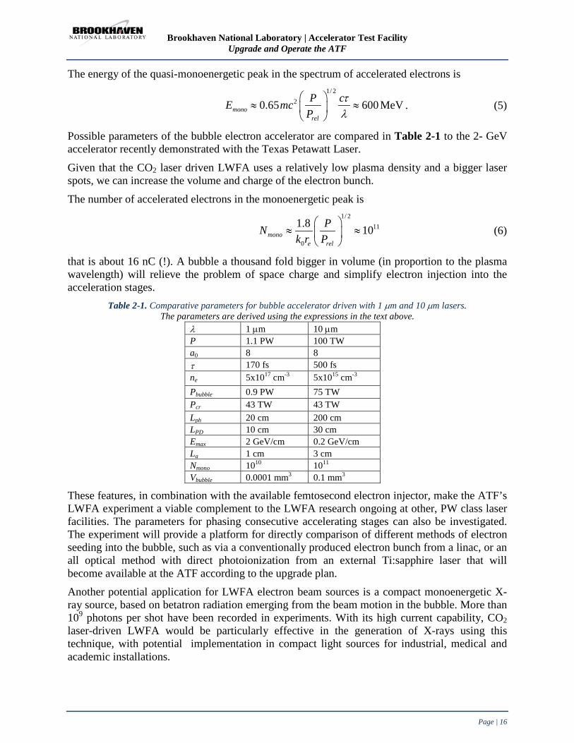
The energy of the quasi-monoenergetic peak in the spectrum of accelerated electrons is 1/ 2
20.65 600 MeVmonorel
P cE mcP
τλ
≈ ≈
. (5)
Possible parameters of the bubble electron accelerator are compared in Table 2-1 to the 2- GeV accelerator recently demonstrated with the Texas Petawatt Laser.
Given that the CO2 laser driven LWFA uses a relatively low plasma density and a bigger laser spots, we can increase the volume and charge of the electron bunch.
The number of accelerated electrons in the monoenergetic peak is 1/ 2
11
0
1.8 10monoe rel
PNk r P
≈ ≈
(6)
that is about 16 nC (!). A bubble a thousand fold bigger in volume (in proportion to the plasma wavelength) will relieve the problem of space charge and simplify electron injection into the acceleration stages.
Table 2-1. Comparative parameters for bubble accelerator driven with 1 µm and 10 µm lasers. The parameters are derived using the expressions in the text above.
λ 1 µm 10 µm P 1.1 PW 100 TW a0 8 8 τ 170 fs 500 fs ne 5x1017 cm-3 5x1015 cm-3 Pbubble 0.9 PW 75 TW Pcr 43 TW 43 TW Lph 20 cm 200 cm LPD 10 cm 30 cm Emax 2 GeV/cm 0.2 GeV/cm La 1 cm 3 cm Nmono 1010 1011 Vbubble 0.0001 mm3 0.1 mm3
These features, in combination with the available femtosecond electron injector, make the ATF’s LWFA experiment a viable complement to the LWFA research ongoing at other, PW class laser facilities. The parameters for phasing consecutive accelerating stages can also be investigated. The experiment will provide a platform for directly comparison of different methods of electron seeding into the bubble, such as via a conventionally produced electron bunch from a linac, or an all optical method with direct photoionization from an external Ti:sapphire laser that will become available at the ATF according to the upgrade plan. Another potential application for LWFA electron beam sources is a compact monoenergetic X-ray source, based on betatron radiation emerging from the beam motion in the bubble. More than 109 photons per shot have been recorded in experiments. With its high current capability, CO2 laser-driven LWFA would be particularly effective in the generation of X-rays using this technique, with potential implementation in compact light sources for industrial, medical and academic installations.

Brookhaven National Laboratory | Accelerator Test Facility Upgrade and Operate the ATF
Page | 17
Extending the compact all optical light source into the gamma range is possible by inverse Compton scattering of the produced electron beams and counter propagating laser beams. An additional advantage of the CO2 laser for this application is the high number of laser photons per Joule of laser pulse energy. Finally, the high current and large volume of the bubble make the CO2 LWFA advantageous for external injection PWFA based on the Trojan Horse concept, for the generation of high-brightness electron beams. Overall, the ATF upgrade will provide unprecedented opportunities for a cost-effective, comprehensive study of a broad spectrum of scientific and technological approaches essential for developing plasma-based, high-gradient, multi-stage accelerators in our advances towards eventual TeV-class electron positron colliders. 1-GeV IFEL Recently, a UCLA group headed by Prof. Pietro Musumeci carried out a milestone IFEL experiment at the ATF (see Appendix B). The experiment completed its first run with the successful demonstration of 100 MV/m energy gradient in a 54-cm helical undulator, dramatically doubling the beam’s energy from 50 MeV to 105-MeV. These numbers set a record in IFEL acceleration, and naturally suggest follow-up experiments to extend the energy reach of the scheme, and to improve the quality of the output beam. The 100 TW CO2 laser upgrade will assure that the ATF is the ideal place to continue IFEL research. According to the UCLA’s letter of intent (Book 2), a new, strongly tapered, helical undulator will support accelerating a 50 MeV beam to more than 1.2 GeV in 1 m with an rms energy spread < 1%, so attaining a new world-record energy gain (>1 GeV) and gradient (>1 GV/m) for a vacuum laser accelerator. Table 2-2 lists the parameters of the proposed 1-GeV IFEL experiment.
Table 2-2. Parameters for BNL’s high-gradient, high energy gain IFEL experiment.
Input beam energy 50 MeV Laser wavelength 10.3 m Laser seed power 100 TW Laser Rayleigh range 25 cm Undulator wavelength (initial-final) 4 cm – 20 cm Final beam energy 1200 MeV Average accelerating gradient >1 GV/m Laser size (at focus) 950 m Undulator length 100 cm Undulator peak field (initial-final) 0.6 – 1.2 T
As was demonstrated in RUBICON, tapering will be achieved by choosing magnets of different thicknesses for each period of the undulator. The amplitude of the magnetic field can be adjusted and tuned by inserting or extracting the magnets. The undulator gap should be larger than 10 mm to allow the full unhampered transmission of the laser.
Due to the extreme tapering, the number of periods is relatively small (8 full periods), with the last two accounting for a large portion of energy gain. This geometry is important as it allows us to use short laser pulses (<0.5 ps), so avoiding the degradation of the interaction due to slippage. Motorized mechanical tuning of the last magnets could enable online fine tuning of the accelerator characteristics, such as output energy, energy spread, and the angle of the output trajectory. The letter of intent from Prof. Musumeci concludes with his statement that “Relatively long CO2 wavelength has significant advantages due to relaxed tolerances in alignment and synchronization.”

Brookhaven National Laboratory | Accelerator Test Facility Upgrade and Operate the ATF
Page | 18
Terahertz (THz) Radiation Source Different physical mechanisms are being explored with the goal of accessing high-power Terahertz (THz) radiation sources desirable for different emerging applications, ranging from material studies to work for Homeland Security. Arguably, the most powerful sources of such radiation are based on collective motion of electrical charges induced by an intense laser.
Efficient energy conversion from a laser beam to THz radiation recently was reported as a by-product of Target Normal Sheath Acceleration (TNSA), ion acceleration experiments whereby a laser was focused on to a thin foil. Hot electrons escape the laser focus at several MeV energies; then they are stopped by the positive charge of the foil. This violent change of the electron’s energy at the picosecond time-scale produces a single-cycle THz radiation that can be collected and collimated by a coin sized parabolic mirror focused at the rear surface of the foil.
CO2 lasers are well known for their high efficiency in producing hot electrons. Indeed, as the ponderomotive energy of the electrons escaping the laser focus scales as 𝛷 = 𝐼 4𝜔2,⁄ a 1 µm laser requires a hundred times higher intensity to induce the same electron energy as does the long wavelength CO2 laser. This wavelength scaling was demonstrated at the ATF where only 1016 W/cm2 of the CO2 laser intensity was required to produce the same ion acceleration via the TNSA mechanism as was 1018 W/cm2 by the solid state laser used elsewhere (Appendix C).
Furthermore, λ=1 µm permits up to a tenfold tighter focus at the diffraction limit. This way, the same ponderomotive electron energy can be realized with a 1 µm laser of the same peak power as a CO2 laser, but notably, in a hundredfold smaller surface area; this results in the corresponding drop in the integral hot electron yield. Therefore, we can safely predict that a 100 TW CO2 laser could be 100 times more efficient in producing hot electrons compared with a 100 TW solid state laser. In other words, a 10 PW solid state laser will be required to match the 100 TW CO2 laser in the production rates of hot electrons and THz radiation. Considering that up to 50% of the CO2 laser’s energy can be routed into generating hot electrons, and that a considerable portion of these electrons end up with forming a rear surface sheath layer while radiating THz photons in the process, we can predict that the proposed method may become the most energy efficient source of single cycle THz radiation. The ATF is in a unique position to facilitate this type of research, which is a natural continuation of our successful TNSA ion- acceleration studies and may culminate in a record-breaking demonstration of a high-intensity THz source upon our further upgrade of laser power.
Importantly, the radiation process has a low laser intensity threshold and can be studied with the already available 1 TW ATF CO2 laser. After the laser upgrade, the ATF will acquire the capability to configure a high-repetition (10 100 Hz) CO2 laser system with up to 10 TW peak power, which is highly meaningful as a practical source of high-power THz radiation for many applications.

Brookhaven National Laboratory | Accelerator Test Facility Upgrade and Operate the ATF
Page | 19
HHG Super Continuum High harmonic Generation (HHG) is another advanced broadband source of radiation that covers the Extreme Ultraviolet (EUV) and X-ray regions. HHG radiation consists of femtosecond-to-attosecond duration pulses with full spatial coherence; accordingly, this makes it very attractive for a range of applications, including tracking the dynamics of electrons in atoms, molecules, and materials. Ultra short X-ray pulses can capture the coupled motions of charges, spins, atoms, and phonons by monitoring changes in absorption or reflection that occur as the state or shape of a material or a molecule changes .
HHG begins with tunnel ionization of an atom in a strong laser field. The electron that escapes the atom is accelerated by the laser’s electric field and, when driven back to its parent ion by the laser, can coherently convert its kinetic energy into a high harmonic photon. The highest energy HHG photon emitted is given by ℎ𝜈𝑐𝑢𝑡𝑜𝑓𝑓 = 𝐼𝑝 + 3.17𝛷, where Ip is the ionization potential of the gas, and 𝛷 = 𝐼 4𝜔2,⁄ is the quiver energy of the liberated electron in a laser field, as was defined in the previous section.
Generating bright, fully coherent HHG beams requires macroscopic phase matching, wherein the laser and high-order nonlinear polarization propagate in phase (at the speed of light) throughout a medium to ensure that the HHG light emitted from many atoms is combined coherently. Phase matching is achieved by balancing the neutral gas and free electron plasma dispersion experienced by the laser; it is possible only up to some critical ionization level that depends on the gas species and laser’s wavelength. Because ionization rises with laser intensity, the critical ionization limits the highest photon energy for which phase matching can be implemented. Recent work explored the wavelength dependence of the HHG yield, which scales as ℎ𝜈𝑐𝑢𝑡𝑜𝑓𝑓 ≈ 𝜆1.7. This scaling was verified in a series of experiments starting with Ti:sapphire lasers operating at a 0.8 µm wavelength with <150 eV EUV photons produced, then extending the continuum to >0.5 keV using 2 µm lasers, and finally to 1.6 keV with a 3.9 µm laser [2]. Using a picosecond CO2 laser should extend the X-ray plateau to 8.5 keV, corresponding to the 80,000th order of CO2 harmonics! Reference to the best recent result with a 3.9 µm laser [2].
Compton Super Continuum Laser Synchrotron Sources (LSS) based on Inverse Compton Scattering (ICS) complement conventional synchrotron light sources through attaining the hard X-ray region with a relatively compact electron accelerator while producing orders-of-magnitude higher peak brightness per single shot. These advantages were experimentally exploited in the linear regime of laser intensities a0<1, where 𝑎02 = 3.7 × 10⁻¹⁹𝐼𝜆2, for I in Watts/cm2 and λ in µm.
As we discuss elsewhere in this proposal (Appendix C), CO2 lasers facilitate high X-ray ICS yields by delivering 10 times more photons per Joule of laser energy compared with 1 µm lasers. Another contributing factor for LSS application of CO2 lasers is their relatively mild diffraction limited focus that is well matched to the electron beam’s size under a practical compact focusing configuration.
Here, we address the second avenue, still experimentally unexploited, to shorter ICS wavelengths attained without the energy increase of compact linear accelerators. This approach is based on a harmonic frequency up-shift. For 𝑎0>>1, numerous harmonics are generated, yielding a continuum of scattered X-ray radiation with harmonics increasing in intensity as (𝜔 𝜔1⁄ )2 3⁄ out to some critical harmonic number nc; beyond this frequency, the intensity of the
Brookhaven National Laboratory | Accelerator Test Facility Upgrade and Operate the ATF
Page | 20
scattered radiation exponentially decreases. This critical harmonic is given by 𝑛𝑐 ≅ 3𝑎03 4 ⁄ for linear polarization, and 𝑛𝑐 ≅ 3𝑎03 2√2⁄ for circular polarization [3]. This number is close to or exceeds 1000 for the laser strength parameter 𝑎0=10 expected by the ATF CO2 laser upgrade. However, this does not mean that the 6-keV X-rays, observed at the ATF when a CO2 laser collided with a 60 MeV e-beam in the linear regime, will be immediately converted into the MeV gamma-region. The maximum ICS energy for nth harmonic ℎ𝜔𝑛 = 4𝑛ℎ𝜔𝐸2
𝑚�2𝑐4+4𝑛ℎ𝜔𝐸
simultaneously drops nearly a hundredfold due to the mass shift effect 𝑚� = 𝑚�1 + 𝑎02. Still, the MeV gamma-region will also be attained upon the ATF’s linac upgrade to 500 MeV.
The average angular spread for the frequency integrated spectrum is ~1 𝛾⁄ . An LSS, based on the nonlinear Thomson scattering of intense CO2 laser from the electron beam has several potentially unique and attractive features that may serve a variety of X-ray spectroscopic and imaging applications. These features include compactness, relatively low cost, tunability, narrow bandwidth, short pulse structure, high photon energy operation, well collimated photon beams, polarization control, and high levels of photon flux and brightness. In addition, for sufficiently cold electron distributions, we can generate short wavelength radiation by the stimulated (coherent) backscattering of intense lasers from beams and plasmas. Stimulated backscattered harmonic generation may provide us a method for producing coherent X-rays via a laser pumped free electron laser. The Compton super continuum and the IFEL depend on a spatial and temporal overlap of the laser beam and the electron beam. These are examples where the laser spot size is constrained by the experiment.
Another example is the Terahertz (THz) source, where the large laser spot size at the same strength parameter leads to a larger number of hot electrons. These are situations in which the CO2 laser excels, and a 100 times more powerful 1 µm laser will be required to explore the effect with the same a0 and beam spot as a 10 µm laser. This last example, highly nonlinear Compton scattering (as others before), highlight the unique opportunities for research made possible by the unique combination of a high-brightness e-beam and the a0=10 10-µm laser available only at the ATF.
2.1.3 Science Enabled by the Electron Beam Energy Upgrade to 500 MeV The 500 MeV upgrade carries with it all the advantages of multiple experiment halls, access to the 100 TW laser beams, generous space for experiments and infrastructure provided by this upgrade proposal. In addition, the availability of a higher energy enables new science.
The combination of the ~500 MeV beam with the synchronized multi-TW lasers makes the ATF quite competitive compared to anything either proposed or in existence.
The cost associated with constructing, operating, and performing experiments goes up with the beam energy. Hence, the science that is enabled by a facility’s electron beam energy must be considered carefully. The new ATF hall will be able to accommodate much higher energy for the electron beam than 500 MeV. We chose 500 MeV as an energy that enables us to do all the exciting new science which is considered in the community, yet is cost effective in construction, operation, and the effort of providing the special needs of experiments.
This energy allows advanced concepts to be tested. For instance, at 500 MeV one may use emittance exchange to generate a beam with linearly ramped current to demonstrate high

Brookhaven National Laboratory | Accelerator Test Facility Upgrade and Operate the ATF
Page | 21
transformer ratio in PWFA with a reasonable deflecting cavity voltage of the order of one megavolt.
500 MeV is also a sweet spot for studies of FEL related concepts, such as E-SASE, EEHG, etc., because the beam can easily interact with 800 nm, or UV lasers. For higher energy beams, the very long period undulator would be required to match the lasers. 500 MeV is well situated between low energy test facilities like NLCTA at SLAC or SPARC in Italy and the multi-GeV energy User Facilities, and therefore could provide critical evaluation of the tested techniques for application in the User Facilities.
Let us consider the beam size aspect. For a given normalized emittance the beam size (given by the geometric emittance), can be made smaller by increasing the energy, albeit rather slowly, as the square root of energy. Smaller beams can be matched to experimental devices that have smaller sizes, as is the case with structure-based, plasma channels, laser acceleration schemes or dielectric acceleration schemes. The ATF beam is already very small. As described in Appendix B, electron beam spot sizes of about 6 microns (standard deviation) with a charge of 300 pC can be generated at certain user chambers. Following the energy upgrade and the new electron gun planned for the ATF, the spot size will be reduced to about 2 microns. This feature can be then combined with the few micron longitudinal beam size pioneered at the ATF using laser modulation or the mask technique. This size is smaller than the CO2 laser wavelength of 10 microns, sufficiently small for a variety of advanced accelerator techniques, including structure-based laser acceleration. In structure-based laser acceleration, the transverse decay distance of the evanescent electric field is of the order of the laser wavelength, thus beam size is important. To increase beam density, bunch length can be shortened below 30 fs with an additional bunch compressor installed in the linac line at an intermediate energy. Several currently running ATF user experiments in dielectric Wakefield and plasma Wakefield may benefit from the upgrade. The simultaneous increase in the Wakefield intensity and beam confinement over a longer distance through the test structure will result in a significant (of the order of 100) increase of effects such as the electron acceleration by Wakefield or Terahertz (THz) radiation yield.
As an interesting example, let us consider the nonlinear regime of Plasma Wakefield Acceleration (PWFA). The smaller beam size at a higher energy will increase the current density and make it possible to conduct experiments in the nonlinear regime of plasma Wakefield acceleration. To increase the beam density effect the electron bunch length may be shortened by an additional bunch compressor installed in the linac, just before the final accelerator sections. This regime allows injection of electrons into the bubble, leading to brightness enhancement by obtaining an emittance smaller by a few orders of magnitude than that of the photoinjector (through what is sometimes called “Trojan Horse” process) as well as energy increase by a large factor thanks for the ATF developed mask technique which enables a large transformer ratio.
As a concrete example, let us consider the nonlinear regime of Plasma Wakefield Acceleration (PWFA). Presently available energy, charge and emittance of the ATF’s electron beam are already sufficient to satisfy basic requirements for efficient driving of PWFA in the nonlinear blowout (“bubble”) regime, which are
𝑛𝑏 𝑛0⁄ > 1, 𝜎𝑟 ≪ 𝜆𝑝 , 𝑁𝑏 𝑛0⁄ 𝜆𝑝3 ≫ 1,
where 𝑁𝑏 and 𝑛𝑏 are the beam charge and density correspondingly, 𝜎𝑟 is the beam rms size, 𝑛0 the plasma density, and 𝜆𝑝 is the plasma wavelength. This allowed to initiate experimental

Brookhaven National Laboratory | Accelerator Test Facility Upgrade and Operate the ATF
Page | 22
studies of “Plasma wakefields in quasi-nonlinear regime” proposed by a UCLA group (PI – J. Rosenzweig).
Tight e-beam focusing below 𝜎𝑟=5 µm is required to satisfy blowout conditions at plasma density 𝑛0 = 1016𝑐𝑚−3 . This focus has been achieved with mini-quadrupole magnet setup described elsewhere in the Proposal. An available 2 cm long capillary discharge provides not just the plasma source; its parabolic radial density profile ensures confinement of the tight focused e-beam over the entire length of the capillary. With the calculated transformer ratio 1.5, 150 MeV/m accelerating gradient is expected from the current ATF experiment.
The planned 500 MeV ATF energy upgrade with an additional bunch compressor, combined with the better emittance of the new ATF photocathode electron gun, will further facilitate meeting the blowout PWFA conditions and ensure that the efficient beam confinement and plasma wake excitation are established over an extended capillary length.
Further upgrade of this experiment to the resonance Wakefield excitation using properly tailored train of electron bunches produced by a “mask technique” perfected at the ATF and described elsewhere in this proposal, can lead to transformer ratio of 4.5 with a corresponding larger energy gain per stage. Thus, the ATF will become a most effective test-bed of different aspects of PWFA physics, including electron injection mechanisms, such as optimizing laser injection for the Trojan Horse scheme.
More examples of the facility and user benefits from the ATF energy upgrade can also be found in other fields of advanced accelerators, as demonstrated by a proposal received from a collaboration of a small business and an international university included in Book 2 of this proposal, “Particle Acceleration by Amplified Wake (PAAW), STI Optronics, Inc. PI - Dr. Wayne D. Kimura, Technical Consultant: Prof. Levi Schächter.
This experiment builds upon the particle acceleration by stimulated emission (PASER) process that was first demonstrated at the ATF. Similar to the PWFA Afterburner concept, this amplified wake can accelerate a trailing electron bunch. This proposed program aims to demonstrate that energy stored in an active medium will amplify an electromagnetic wake produced by a series of electron bunches. The proposed upgrade of the ATF electron beam to 300-500 MeV along with its existing CO2 laser, which is needed to drive an inverse free electron laser (IFEL) to create the microbunches, will be an ideal environment to pursue the PAAW experiment.
CO2 laser discharge will be used for the active medium. The amount of energy that can be extracted from the active medium is proportional to the number of excited molecules. Hence, high energy gain favors high molecular density in the CO2 discharge. A CO2 gas pressure of several atmospheres, which is an order-of-magnitude higher than the first ATF’s PASER proof-of-principle experiment, is desired. This necessitates using thicker electron beam windows to contain the gas mixture in the CO2 discharge cell. Both the thicker windows and higher gas pressure will cause greater scattering of the electrons. To minimize this scattering, it is imperative to operate with as high electron beam energy as possible. The energy of 300 MeV is approximately the minimum energy; 500 MeV would be even better. Up to 1-1.5 GeV/m acceleration energy gradient is expected.
The higher energy electron beam enables one to access shorter wavelength radiation through Inverse Compton Scattering (ICS). The ICS photons are mono energetic, with spectral bandwidth dictated by the energy spread and emittance of the electron beam and the interaction length

Brookhaven National Laboratory | Accelerator Test Facility Upgrade and Operate the ATF
Page | 23
between the laser and the electron bunch. The photon beam is also contained in a small cone with the opening angle determined by the electron energy and the selected bandwidth of the emitted radiation. All of these parameters can be controlled to a large extent by electron beam optics.
The CO2 and Ti:sapphire laser beams will be transported to EH#3 enabling research towards gamma sources applicable to polarized positron production for e+-e- colliders, as well electron-gamma and gamma-gamma colliders. Using the ATF’s Ti:sapphire laser, one could generate gamma rays up to 8 MeV. A similar energy range but with a photon yield higher by orders-of-magnitude can be achieved with harmonics of the high-power CO2 laser, as has been described in the previous section.
Beam conditioning is another category of experiments that benefit from the ATF energy upgrade. A good example from this category is the shot noise suppression experiment that has been conducted by the Tel Aviv University at the ATF and published in various venues, including Nature Physics. This experiment proved the ability to suppress the current noise below the shot-noise limit at optical frequencies, and as a result to increase the coherence of the emitted radiation from devices such as FEL’s. The challenge and interest will be to observe it at shorter wavelengths and higher beam energies. Indeed we have received a proposal for the extension of this experiment to higher energies. A 300 MeV beam would satisfy the validity conditions for noise suppression schemes at wavelength λ =100nm. The detailed user proposal “Experimental Study of Electron Beam Micro Bunching Dynamics and Shot Noise Suppression Effect in High Energy e-beams Proposal, A. Gover, A. Nause - Tel Aviv University” is included in Book 2. This new research project is aimed towards extension of the understanding and control of the effect at higher beam energies and shorter wavelengths where it has significant implications to the development of advanced FELs.
These are just few examples out of more than twenty possible experiments based on the upgraded ATF beam parameters and summarized in Table 2-3. Further discussion on the science enabled by the electron beam energy upgrade is provided in the next section.
2.1.4 The Overall Vision of New Science at the Upgraded ATF The CO2 laser upgrade and the electron beam energy upgrade provide two independent parameters. Listing experiments (or more generally classes of experiments), enabled by these parameters allow us to view the scientific scope of the proposed upgrades. This material is presented in Table 2-3. The experiments listed fall under multiple categories: Completed, active, proposed and future. A particular type of experiment can fall into more than one of these categories, for example it could be completed for a lower electron beam energy and / or laser power, but may have renewed merit with the extended parameters. Active and proposed represent proposals that have been submitted to the ATF Program Advisory Committee. Of these, “active” means that the proposal has been approved and the experiment is already active in the ATF, while the “proposed” experiments have yet to be evaluated by the ATF Program Advisory Committee (PAC). Future experiments are ideas we considered, based on our past experience, to of interest to the ATF users. As was the case in the past, potential future experiments will be communicated to the accelerator science community through the usual means of conferences, workshops, and ATF User Meetings. Section 2.1.1 and Section 2.1.2 provides details regarding some of these future possibilities.
One should note that the scientific case made in this section does not include the possibilities offered by the ultra-high current (over 300 mA CW) Superconducting RF Energy Recovery

Brookhaven National Laboratory | Accelerator Test Facility Upgrade and Operate the ATF
Page | 24
Linac described in Section 3. The SRF ERL is considered a future option that will be enabled by the move of the ATF to Building 912 (where the ERL is located). The ERL will be completed with funding by other sources, and may then be operated in part by the ATF and other C-AD staff for user experiments.
The number of experiments in the “future” category will clearly grow once users begin to work in the upgraded ATF facility. Yet already the number and variety of the experiments in Table 2-3 is quite large. Therefore, we provide a graphic display of the table below. Figure 2-5 shows the landscape of the ATF’s past, present, and future science reach in terms of electron beam energy and CO2 laser power. The vertical scale provides the number of experiments distributed over this parameter space. Solid bars shows experiments, which have already been completed or are in progress, and translucent bars indicate experiments that are future planned or possibility enabled by the proposed ATF upgrade. Electron beam experiments are marked in blue, laser beam experiments are marked in red, and synchronized, interacting laser and electron beam experiments are in violet.
The number of experiments indicated by the vertical dimension of the bars is very high for past experiments because of the long time period over which ideas for new science were stimulated by the existence of the ATF and its capabilities. Surely, we did not anticipate this large variety at the time the ATF was proposed, or even in its early days of operations. We definitely expect that over the next 10 years, the numbers and types of experiments in the new space will grow and new science will emerge. Clearly the parameter space of science possibilities is vastly increased by the proposed upgrade. Finally, one should note that the synchronized, interacting laser and electron beam experiments, which occupy most of the parameter space and opportunities, are the hallmark, area of expertise and so far a unique feature of the ATF among accelerator science User Facilities.
Table 2-3. ATF experiments, past, present and future with laser and electron beam parameters, excluding SRF ERL.
Experiments 80M
eV
300
MeV
500
MeV
< 1
TW
1T
W
10T
W
100
TW
:sap
pe S
tatu
s
Photocathode R&D Completed New generation photocathode RF gun test program Completed Measuring Coherent Synchrotron Radiation (CRS) effects in high-brightness electron beams x Completed
Coherent diffraction radiation measurements of bunch Length x Completed Non-intercepting OTR/ODR diagnostics x Completed Plasma Wakefield Acceleration, measurement of focusing and acceleration x Completed fs bunch trains x Completed Inverse Cherenkov acceleration x x Completed Inverse FEL Accelerator x x Completed High Gain Harmonic Generation (HGHG) FEL x x Completed Inverse Compton X-ray source x x Completed Staged Electron Laser Acceleration (STELLA) x x Completed Extreme UV source based on CO2 laser interaction with Xe micro-droplets x Completed Particle Acceleration by Stimulated Emission of Radiation (PASER) x x Completed Laser Cyclotron Auto‐Resonance Accelerator (LACARA) x x Completed Smith-Purcell effect experiment x Completed A SASE-FEL Experiment, VISA x Completed Study of Compton scattering of picosecond electron and CO2 beams x x Completed Micro-undulator FEL Experiment x Completed Stimulated Dielectric Wakefield Accelerator x Completed

Brookhaven National Laboratory | Accelerator Test Facility Upgrade and Operate the ATF
Page | 25
Experiments 80M
eV
300
MeV
500
MeV
< 1
TW
1T
W
10T
W
100
TW
:sap
pe S
tatu
s
Electron beam pulse compression and study of CSR effects x Completed X-ray transition radiation generated by MeV electrons in a multilayer solid target x Completed
Quad-cavity high precision beam position monitor x Completed Delta undulator x Completed Ion and proton source through laser driven plasma acceleration x Completed RUBICON – 220 MeV/m -130 MeV energy gain helical IFEL experiment x x Active Non-linear inverse Compton scattering x x Active Measurement of coherent THz radiation using a real-time interferometer x Active AXIS, 5 μm damage test x Active Single electron detection experiment x Active High-power intra-cavity ICS x x Active Plasma Wakefield Acceleration in quasi-nonlinear regime x x x Active/Future Multi-bunch Plasma Wakefield Acceleration x x x Active/Future High-gradient, high-field dielectric wakefield acceleration x x x Active/Future Advanced Imaging and ultra-fast material probing with ICS x x x x x x Active/Future Wakefield Measurements Holography x x x x Active/Future Beam Manipulation by THz Self-Wakefield x x x Active/Future A high resolution transverse diagnostic based on fiber optics x x x Active/Future Study of wall roughness effects at BNL ATF x x x Active/Future X-band travelling wave deflection mode cavity for ultra-fast beam manipulation x x x Active/Future High-brightness picosecond ion beam source based on BNL TW CO2 Laser x x Active/Future Next-generation Photoinjector: two RF harmonics gun Proposed Ultrafast High-brightness electron source Proposed Attosecond beam characterization x x x Proposed Micro bunching dynamics and shot noise suppression effect x x Proposed 1 GeV/m IFEL x x Proposed Particle acceleration by amplified wake (PASER) x x x Proposed Proton source using plasma shock-wave acceleration aimed at 200 MeV x Proposed Bio-medical experiments towards using compact laser driven ion accelerators x x Proposed Advanced phase space manipulations x x Future
High-brightness X-ray channeling radiation source x x Future ICS Gamma-ray source x x Future Two color ICS x x x x x x Future Compton super continuum x x x x Future Application of ICS photons x x x x x x Future High-power THz source x x x Future High Harmonic Generation (HHG) super continuum x x x Future PWFA with density transition electron injection x x Future PWFA with beam triggered ionization injection x x Future Trojan Horse original: Ultra-low emittance by injection into a plasma bubble x x Future All optical Trojan Horse: Ti:sapp. injected electron beams into a CO2 LWFA x x Future FEL gain from PWFA accelerated low-emittance beams x x x x x Future PWFA with high-repetition rate of up to 40 MHz x x x Future Self-modulated LWFA x x Future 20 GeV/m high luminosity bubble LWFA x Future High-intensity betatron radiation research x Future LWFA bubble probing with external electron beam diagnostic x x x x Future Laser driven neutron generator x Future Test bed for staged wakefield acceleration with external electron injection x x x x Future

Brookhaven National Laboratory | Accelerator Test Facility Upgrade and Operate the ATF
Page | 26
Figure 2-5. shows the landscape of the ATF’s past, present, and future science reach in terms of electron beam energy and CO2 laser power. The 5-fold increase in electron beam energy and the 100-fold increase in the synchronized CO2 laser power open up a large, unexplored, area for new science. The size of the bars corresponding to the current laser power and electron beam energy indicates the sum of new science and past experiments at the ATF. With over two decades of exploration, these possibilities added many experiments, much more than were foreseen at the time that the ATF began operations. The details of the experiments that make up Figure 2-5 are provided in Table 2-3 above. The new experiments that are derived from the high-power CO2 laser synchronized with the upgraded electron beam, make up the largest area in the parameter space. These experiments provide a glimpse of new exciting science, unique to the ATF and cannot be found at any other user facility, current or proposed. It is just a glimpse, since our past experience shows that with time, many new experiments will be invented and proposed to take advantage of this vast increase in parameter space.
Figure 2-5. ATF science reach parameterized by the electron beam energy and CO2 laser power. The vertical scale
shows the number of experiments. Solid bars show experiments, which have been already completed or are in progress. Translucent bars indicate future experiments. Electron beam experiments are marked in blue, laser beam
experiments are marked in red, and synchronized, interacting laser and electron beam experiments in violet.
The ATF Upgrade “The proposed laboratory upgrade, including the branching of experimental beam lines for accessing higher energies, the expanding of the high-power infrared laser capabilities and delivery to users, and continued emphasis on high-end diagnostics will position the ATF as the premier user facility for innovative scientific experiments in advanced acceleration and radiation generation, from X-rays to terahertz. The various capabilities will keep the ATF at the forefront of accelerator/laser based research and competitive on the international scale. I look forward to participate in, and utilize, the upgrades, including development of X-band infrastructure for longitudinal profile characterization and beam energy spread mitigation, and continued studies on high-gradient wakefield acceleration, with plasma interactions and dielectric based structures, exploiting the enhanced beam parameters. I enthusiastically support this endeavor.” Gerard Andonian, Ph.D., University of California Los Angeles, Department of Physics and Astronomy

Brookhaven National Laboratory | Accelerator Test Facility Upgrade and Operate the ATF
Page | 27
2.1.5 Efficiency, Productivity and Turn-over Time The upgrade will provide the ability to set up experiments in one or more beam lines (while operating with beam in another beam line), each will have complete radiation shielding and interlock systems for safe operations. As we will show below, the proposed upgrade will allow much more beam operation time for users and will reduce down-time, thereby reducing the time to carry out an experiment by nearly a factor of two. The benefits of reducing the time to complete a user’s experiment are that it provides a better return on the investment in the operations of the facility and that it increases the rate of scientific output.
The reduction in time to carry out an experiment is particularly important to two segments of our stakeholders: 1). Graduate students who need to finish their thesis research in a finite time, and 2). Small businesses who have to get a return on their investment and who are often funded by SBIR / STTR grants, which have limited time to complete their work. The pie chart in Figure 2-6 shows operation statistics of the present ATF. Specifically, it highlights the effectiveness of beam usage calculated hourly when all electron beam projects are run in one experimental hall. This situation will be resolved in the new building 912, where the electron beam can be directed into two shielded and radiologically independent halls. Accelerator operation takes approximately 53% of the time, while experiment setup and installation takes more than one third of it. To handle the higher impact work associated with this improvement, we propose to increase the Full Time Equivalents (FTEs) at the ATF by two people. This will also eliminate the 7% beam time loss due to conferences and vacation. Based on Figure 2-6, we conclude that the availability of two independent experiment halls and extra staff approximately doubles the beam time for each experiment. Figure 2-6. ATF operation statistics collected over fiscal years 2011, 2012 and part of 2013. The pie chart shows hourly time when the facility ran the electron beam (blue); when the ATF was open for experiment setup\installation (red); when the ATF was down for scheduled and unscheduled maintenance (green); and when the ATF had no scheduled beam time due to holidays, or staff shortage due to conferences and workshops (purple).
2.2 The ATF Upgrade Building The relocation of the ATF to Building 912 will improve the performance and enable new features of the facility in several ways. The beam quality and machine stability will improve due to the application of state-of-the-art survey and beam component mounting systems. Our survey accuracy and stability experience is based on survey development at BNL for the newest high-brightness light source e.g., the National Synchrotron Light Source (NSLS-II). The experimental hall and the users’ devices will be fully surveyed and characterized by laser tracker. Using this system, we can locate components to within 10 microns. Or in other words, know where that component is within 10 microns from a reference location or any other pre-surveyed component in the experimental hall.

Brookhaven National Laboratory | Accelerator Test Facility Upgrade and Operate the ATF
Page | 28
The concrete pedestal system and near net zero Coefficient of Thermal Expansion (CTE) support system will be designed to maintain position of the beam line components to less than 5 microns. The HVAC cycling will be adjusted to minimize this effect. The appropriate support and damping materials will assure that all critical component assemblies will have a high enough natural frequency that micron acoustic stability can be achieved.
We work closely with the users concerning their need for stability and design their experiment appropriately to achieve it.
A key advantage of the planned facility upgrade is much increased space for the accelerator, the experiments and the various upgrades, as shown graphically in Figure 2-7, which is a 3D Model of Building 912.
Figure 2-7. A 3D Model of the proposed facility, laid out in Building 912, with major components labeled. The
facility is placed on top of large concrete slabs separated by trenches. Shielding blocks and the roof are made of concrete and are positioned by an overhead 40 ton crane. The roof shielding can be removed and replaced to insert
and remove very large equipment.
The other feature, which will be enabled in the new location, is the availability of independently shielded experiment halls. A switching dipole magnet will redistribute the electron beam to one hall or another. Each hall will have an identical beam line structure mirrored along the axis where accelerator sections are located. It will allow the same advantages. Presently, the ATF has additional flexibility to setup the experiment in one hall, while the electron beam is delivered to another hall. Each beam line exiting the switching dipole will have a shutter system to prevent beam from entering any non-interlocked experimental hall. Furthermore, the shutters and the switching magnet area will be shielded to eliminate risks to any user. Beam schedule will be adopted to run two experiments simultaneously. At the time when both experiments will be ready for beam delivery, the working shift can be extended and beam time can be shared.

Brookhaven National Laboratory | Accelerator Test Facility Upgrade and Operate the ATF
Page | 29
Figure 2-8 shows the Building 912 Proposed Layout, in terms of total floor space, viz., an increase from 5,000sf to 15,000sf, which also allows for future expansion of the ATF.
Figure 2-8. Proposed layout of the new ATF electron accelerator as designed for building 912.
The provision of ample space to mount complex experiments is another important feature of the building, and it goes together with ease of access of large items anywhere in the facility thanks to the 40 ton overhead crane and removable roof shielding blocks. The increased space also reduces

Brookhaven National Laboratory | Accelerator Test Facility Upgrade and Operate the ATF
Page | 30
installation time of experiments by simplifying and improving the access to components and the maintenance of equipment.
The extent of the planned facility upgrade can be understood better in the numerical increases summarized below:
• Total floor space, from 5,000sf to 15,000sf • Number of independent e-beam experimental halls, from 1 to 3 • Number of beam lines, from 3 to 6 with a potential for further expansion • Laser rooms, from 1500sf to 4000sf to allow for planned upgrades to the lasers • Main Control Room space, from 120sf to 1000sf • New Laser Control Room, 400sf • Users experiment preparation space, from 700sf (presently shared with laser experiments)
to a dedicated separate room with 1400sf • Dedicated linac and RF test space (newly introduced), 1300sf to allow high-gradient
R&D and testing
These numbers clearly illustrate the possibility of increasing the number, size and complexity of user’s experiments that can be simultaneously prepared and served by the ATF after the facility’s planned upgrade. Furthermore, it allows and involves considerable modernization of its major physical equipment, such as the linac and lasers.
2.3 Electron Beam Lines Design – Stage I The upgrade will provide the building and commissioning of the linear accelerator and four experimental beam lines, two in each of two experimental halls (see Figure 2-9).
Figure 2-9. The sections to be constructed and commissioned with major components highlighted in red.
Based on the current ATF design, the accelerator tunnel section consists of the photocathode gun, where the beam is to be generated with energy 4.5 MeV; the linac where the beam will then be accelerated to an energy of 30 – 80 MeV (30-100 MeV capable with the X-band linac section), as per experimental requirements; the chicane, for bunch length compression; magnetic optics, for tuning beam parameters and a switching magnet to direct the beam into one of two experimental halls.

Brookhaven National Laboratory | Accelerator Test Facility Upgrade and Operate the ATF
Page | 31
Each of the experimental halls EH#1 and EH#2 contain two beam lines, one short auxiliary beam line and one long main beam line. EH#1 is designed with wakefield type experiments in mind having a mask for beam shaping and multi-bunch production (see Mask Technique in Beam Conditioning in Appendix B and Appendix C), an experimental chamber and a deflector cavity with X-band linac for longitudinal bunch measurements (see Appendix B). EH#2 is designed for electron beam laser interaction experiments, such as Compton scattering. The main beam line begins after the switching magnet with a long “dogleg”, double-bend dispersion section. When the switching magnet deflects the beam, in order to direct it to one experimental hall or the other, horizontal dispersion (i.e., for some particles ∆p/p ≠ 0, where p is the nominal momentum for a particle at the design energy) is introduced. Introducing a second bend, together with quadrupole magnets, then compensates this dispersion. High dispersive regions are ideal for energy related tasks, measurements, collimation etc. After the dogleg section the beam passes through two quadrupole triplets, which give the operator the means to focus the beam to as small as 6 μm rms transverse size. The beam is focused to this size at the interaction point, which is inside an experimental chamber designed for a given experiment’s requirements. Figure 2-10 shows the results of optics calculations by MAD (Methodical Accelerator Design), for a wakefield type experiment (requiring beam passage through a small cylindrical capillary placed inside the experimental chamber) on the main beam line in EH#1. It can be seen that the high energy slit (energy collimator) and mask (see on mask technique in Appendixes B and C) are both in the regions where dispersion Dx (green line) is large. At the interaction point, the beam size is small and round suitable for transmission through small capillary channels; we obtain there βx/y=0.1 m and αx/y=0. This also ensures high energy resolution on the spectrometer screen.
It also provides improved energy resolution on the spectrometer screen. (See the following section, Beam Line Component and Sub System Descriptions: Spectrometers and Beam Dumps).
Figure 2-10. Results of optics calculations performed using MAD for the main beam line.

Brookhaven National Laboratory | Accelerator Test Facility Upgrade and Operate the ATF
Page | 32
The auxiliary (short) beam line, in both EH#1 and EH#2, will, in the first instance, be used for experiments not requiring an experimental chamber, for example beam studies and instrumentation R & D. This beam line has been left without experimental chamber and spectrometer to allow future installation of any user designed chamber or device. Figure 2-11 shows the results of optics calculations designed to achieve a small round beam (βx/y=0.1 m and αx/y=0) at the potential interaction point towards the end of the beam line.
Figure 2-11. Results of optics calculations performed using MAD for the auxiliary beam line.
The Stage I beam line configuration is based on the current ATF beam line design perfected over two decades of machine operation. Table 2-4 compiles design parameters for four new experimental beam lines.
Table 2-4. Beam line design parameters for Stage I ATF upgrade.
Parameter Value Beam energy at gun exit (MeV) 4.5 Beam energy at linac exit (MeV) 30 - 80 Beam emittance (mm mrad) 1-3 Bunch charge at IP (nC) 0.001 -3 Repetition Rate (Hz) 1.5 Bunch length out of gun (ps) 5-8 Compressed bunch length (fs) ~100
Maximum dispersion (m) ~2=Main ~0.5=Auxiliary
High energy slit available yes Mask available Yes in Main Laser interaction available Yes in EH#2 Main
The experimental program at the ATF is well established. It is the intent to continue operations at the current ATF until the upgraded facility is ready for experimental operations. At this time there are a number of experiments that would be ready for immediate integration into the new facility.

Brookhaven National Laboratory | Accelerator Test Facility Upgrade and Operate the ATF
Page | 33
Figure 2-12 shows the locations of the existing experimental chambers which will be used for these experiments.
Figure 2-12. Proposed plan for insertion of current and near future experiments into the upgraded ATF. Detailed
information about these pre-existing experimental chambers may be seen in Appendix B.
Each of the experimental chambers, listed in Figure 2-12, is currently used for multiple experiments with the contents of the chambers exchanged on a monthly or even weekly basis. Table 2-5 shows a sampling of the possibilities for the early days of operations at the new ATF location. Here, current and near future experiments are matched to the chambers that satisfy their requirements. As shown in this table, the upgraded facility will be extremely flexible in terms of experiment location, allowing maximum advantage to be taken of the availability of multiple experiment halls.
Table 2-5. List of experiment locations matched to chambers and relevant experiments. The experiment codes are according to the current ATF classification of approved user experiments
Location Chamber Type Experiment Name Code
01 None (insertion devices) Electron beam micro bunching dynamics AE48
1A1 Electron laser (Appendix B: Fig. 1-27)
Advanced imaging/ultra-fast material probing with inverse Compton scattering AE45
Non-linear inverse Compton scattering (feasibility study) AE53
1A2 Electron-Plasma (Appendix B: Fig. 1-28)
Multi-bunch Plasma Wakefield Acceleration AE31 High-gradient, high-field dielectric wakefield acceleration AE39 Measurement of coherent terahertz radiation using a real-time interferometer AE49 Plasma Wakefields in the Quasi-Nonlinear Regime AE50 Study of wall roughness effects at BNL ATF AE51 Beam Manipulation by THz Self-Wakefield at the ATF AE52 A high resolution transverse diagnostic based on fiber optics AE56
1B TBD - as needed Single electron experiment (no chamber required) AE55
1C Laser injection (Appendix B: Fig. 1-31) Future proposals AE52
2A1 Dielectric Wakefield Multi-bunch Plasma Wakefield Acceleration AE31

Brookhaven National Laboratory | Accelerator Test Facility Upgrade and Operate the ATF
Page | 34
Location Chamber Type Experiment Name Code (Appendix B: Fig. 1-30) High-gradient, high-field dielectric wakefield acceleration AE39
PWFA Holography AE43 Measurement of coherent terahertz radiation using a real-time interferometer AE49 Study of wall roughness effects at BNL ATF AE51 Beam Manipulation by THz Self-Wakefield at the ATF AE52 A high resolution transverse diagnostic based on fiber optics AE56
2A2 Electron-laser (Appendix B: Fig. 1-27)
Advanced imaging/ultra-fast material probing with inverse Compton scattering AE45
Non-linear inverse Compton scattering (feasibility study) AE53
2B TBD - as needed RUBICON - 220mEv/M -130 MeV energy gain helical IFEL experiment AE41 Single electron experiment (no chamber required) AE55
3A Future, User designed Future proposals EH#4
CO2 room Ion Generation
(Appendix B: Fig.-32) AXIS, 5 μm damage test (feasibility study) AE54 High-brightness picosecond ion beam source based on BNL TW CO2 laser AE35
2.4 CO2 Laser Power Upgrade The evolution of the ATF’s picosecond CO2 laser up to this time centered on significantly shortening the pulse’s duration (from 200 ps to 5 ps) and increasing its energy (from 200 mJ to 5 J). We achieved this by building up the system, and by adding components and features that qualify as “evolutionary” upgrades. Further progress towards much higher peak powers will require devising next-generation ultra-fast CO2 laser technology by implementing “revolutionary” methods never employed previously with gas IR lasers. Our plan includes four major innovations: 1). All solid state, femtosecond, optical parametric amplifier front-end; 2). chirped pulse amplification; 3). self-chirping and femtosecond compression; and 4). using CO2 isotopes in amplifiers. These developments parallel similar revolutionary improvements made years ago in solid state laser technology where ultra-fast terminology now is applied conventionally to lasers of 100 fs and shorter pulse length.
The upgrade of the ATF’s CO2 laser will open new research programs at BNL. By our offering a unique, compact and powerful laser, new scientific missions will be enabled including the following ones:
• Ion acceleration to radiotherapy relevant energy creation of ultra bright sources of monochromatic X-rays through Compton scattering on electron beams;
• High luminosity laser wakefield acceleration of electrons;
• Other strong field applications that complement cutting-edge projects conducted or planned with the most powerful solid state lasers worldwide.
CO2 Laser Power Upgrade Highlights A unique strength of the ATF is the interaction of high-power ultra-short pulsed lasers with high-brightness electron beams. Our development of such lasers at long wavelengths (~10 µm) led to recent breakthroughs in generating mono-energetic ion beams from the laser bombardment of gas jets, a research field with game-changing potential for radiotherapy. To facilitate our quest to achieve this goal and to meet other challenging applications in strong-field physics, BNL will provide Program Development funding totaling $2M over the 3 years for upgrading the CO2 laser to the level of 100 TW.

Brookhaven National Laboratory | Accelerator Test Facility Upgrade and Operate the ATF
Page | 35
Detailed Plan Our upgrade of the ATF’s CO2 laser system to 100 TW level will be achieved through three main thrusts:
1) Adding stages to the laser’s amplification chain. 2) Applying known ultra-fast solid state laser techniques towards the next-generation ultra-
fast CO2 laser technology by: a) implementing the Chirped Pulse Amplification (CPA) technique in the CO2 laser; and, b) installing a high-power Optical Parametric Amplifier (OPA).
3) Implementing femtosecond pulse compression.
The program also entails building up the many auxiliary systems, including transport, controls, supply lines, and controlled clean room environment.)
Optical Parametric Amplifier (OPA) After thorough consideration, we selected and currently are commissioning a new front-end of the ATF CO2 laser system, i.e., an optical parametric amplifier (OPA) based on nonlinear mixing crystals pumped with a Ti sapphire laser.
This all solid state seed pulse generator manufactured by Quantronix Co. produces 35-μJ, 350-fs (FWHM), 10-micron pulses, shown in Figure 2-13. The natural bandwidth of the 350-fs injection pulse is about threefold broader than that of a CO2 amplification band. Hence, the pulse spectrum will shrink upon amplification, with a simultaneous rise in its duration to 1.5-2 ps. This affords us a two-to-three-fold improvement over the current configuration, wherein the minimum duration of the pulse is limited at ~5 ps by the speed of optical switches used for generating the injection pulse. Another improvement follows from the fact that the broadband injection pulse will extract excitation energy simultaneously from the manifold of about 15 rotational sub-levels on the upper vibrational laser level, compared to only ~3 rotational sub-levels interacting with a 5-ps pulse. We estimate attaining an order-of-magnitude higher total increase in the peak power due to pulse shortening (a factor of 3) and better extraction of energy (again a factor of 3). Also, very important for us and our many users are a smaller form factor, the simpler operation, and, potentially, the shorter maintenance times of the solid state system compared to the pulse slicing setup of our current configuration.
Figure 2-13. Compact solid state femtosecond OPA manufactured by Quantronix Co. (left) opened for alignment by the ATF laser operators (right).

Brookhaven National Laboratory | Accelerator Test Facility Upgrade and Operate the ATF
Page | 36
Figure 2-14 shows the layout of the 5 TW 10 micron laser system after installing and implementing our new, seed pulse generator.
Figure 2-14. Layout of the ATF's 10-micron laser system after implementing the all-solid state seed-pulse generator.
Amplifier Chain We will build a new amplifier chain starting from the existing ATF CO2 laser system. The expansion of the amplifier chain, aimed primarily at boosting the laser energy, will encompass the following three steps:
Step 1. We will extract more energy from the initial regenerative amplification stage. Presently, this amplification stage (SDI Co., UV-pre-ionized discharge, 10-atm, 12-mm aperture, isotopic regenerative amplifier) is limited to ~5 mJ output energy. By augmenting this stage with a larger aperture CO2 amplifier (~30 mm), we will greatly increase the output, to 30-50 mJ.
To accomplish this step, we will purchase another SDI laser amplifier custom developed to our specified requirements (see Figure 2-15).
Figure 2-15. The commercial 10-atm CO2 laser manufactured by SDI Ltd. (RSA).
Note that UV-preionized SDI amplifiers are configured to operate at 10 Hz repetition rate. Combining two such amplifiers of gradually increased aperture with an OPA allows the assembly of a complete terawatt class laser system operating at 10 Hz repetition rate. The detailed performance of such a system will depend upon design choices such as possible OPA output upgrade, implementing pulse stretching before amplification and compression after, optimum balance between regenerative and multi-pass amplification schemes. Estimates indicate the possibility of reaching up to 5 TW output at 10 Hz repetition rate with the efficiently

Brookhaven National Laboratory | Accelerator Test Facility Upgrade and Operate the ATF
Page | 37
configured system. Such regime will benefit aforementioned driving high average power Terahertz (THz) and X-ray radiation sources, etc.
Step 2. We will modify an existing multi-pass, 10-cm aperture, X-ray pre-ionized, CO2 laser amplifier manufactured by Optoel Ltd. to have fewer passes but with simultaneous expansion of the laser beam’s aperture at the early passes. Because of the larger energy input from the initial amplification stage, the multi-pass amplifier will attain the same energy per beam area, per unit bandwidth. However, because the expanded beams cover a larger active area, the broader spectrum (ensured by the OPA), and the longer pulses (due to CPA stretching as detailed below), the extraction energy from the Optoel amplifier will be much higher than that in the current system, reaching 30-45 J. This is to be compared with the current level of less than 10 J, a remarkable improvement.
Step 3. We will build an additional final amplifier, according to the existing blueprints (see elements of this laser illustrated by Figure 2-16.), with only one or two amplification passes and efficient energy extraction from the entire active area. The expected output energy will be above 100 J.
Figure 2-16. New laser amplifier to be built from blueprints available from previous Optoel contract.
The right image shows essential part of the laser’s active head depicted at the left.
Chirped Pulse Amplification (CPA) The invention of CPA was a dramatic breakthrough in the field of solid state laser technology, and we expect that its effect on gas lasers will be equally invaluable. Although the nonlinear indices of the gaseous active media are smaller than those of the solid state ones by orders-of-magnitude, the presence of transmitting optics and long beam paths make the nonlinear effects (Kerr lensing, self-phase modulation) also a problem for high peak power CO2 lasers. Resolving it is vital for making further progress in increasing the peak power. For example, a recent reconfiguration of the ATF’s regenerative amplifier, where we replaced an intra-cavity Pockels-cell switch based on a 5-cm CdTe crystal with a 500 μm Ge semiconductor switch, satisfactorily raised the energy of the amplifier output from 1 mJ to ~10 mJ. In the next-generation CO2 lasers, we aim to reach higher peak intensities, also considering that the CPA is the way to proceed.
The high energy extraction from the active medium, described above, and its transmission through the amplifier windows is possible provided that the CO2 seed pulse stretches to 100-200ps with diffraction gratings. We plan to introduce a stretcher after the OPA or, alternatively, another early amplification stage.

Brookhaven National Laboratory | Accelerator Test Facility Upgrade and Operate the ATF
Page | 38
Figure 2-17 shows the principle optical design of a stretcher and a compressor for CPA.
Figure 2-17. Principle optical diagram of CPA components with
picosecond pulse stretching and compression using diffraction gratings.
The diffraction grating compressor will be housed in a vacuum chamber, and will be placed before the final focusing parabola at the applicable experiment location (ion acceleration or laser/e-beam interaction point). The technical characteristics of the CPA apparatus are compiled in Table 2-6.
Table 2-6. Technical parameters of the CPA apparatus.
Grating line density 75 mm-1
Grating blaze angle 22° Grating angular dispersion @ 10 µm 0.081 rad/µm Stretcher grating: 58×58 mm2, Al on Zerodur substrate, replica Stretcher configuration Folded, single grating Design stretching factor 680 ps/µm Example stretching 1 ps -> 100 ps
(FWHM, bandwidth-limited Gaussian pulse) Compressor gratings: Stage 1 (5-10 TW): 165×220 mm2, Al on Cu substrate, replica
Stage 2 (100 TW): 320×320 mm2, bare Al, master Compressor configuration Unfolded, 4-grating Compressor vacuum rating 10-8 Torr
After compressing the pulse back to ~1.7ps, the combination of CPA with the improved energy output from the amplifier chain will produce 50 TW peak laser power. Our projection is supported by simulations of the CO2 CPA implementation which demonstrate that despite noticeable narrowing and modulation of the laser pulse’s spectrum during amplification, significant recompression is still attainable.
Femtosecond Pulse Compression Frequency chirping, induced by the Kerr effect when transmitting the laser pulse through a Xenon gas, enables additional compression of the pulse after the diffraction gratings. The effect has been previously demonstrated on a small scale with a CO2 laser and is well characterized through simulations that verify the likelihood of compressing 2 ps CO2 laser pulses down to 0.5 ps with high conversion efficiency (see Figure 2-18). We expect to realize a rise in the final peak power from 50 TW to 100 TW upon our implementing this process.

Brookhaven National Laboratory | Accelerator Test Facility Upgrade and Operate the ATF
Page | 39
Figure 2-18. Principle diagram for femtosecond pulse compression method [4]
The principle optical layout for the 100 TW CO2 laser system is shown in Figure 2-19.
Figure 2-19. Principle diagram of the ATF CO2 laser system after the proposed 100 TW power upgrade.
100 TW Implementation Plan
The ATF CO2 laser upgrade to 100 TW peak power is being planned independently from this proposal, under funding from BNL’s Program Development funds.
Although we already have initiated work on certain elements of the power upgrade - and will continue them within the present ATF envelope in Bldg. 820, the full advantages of this upgrade will be difficult to realize due to cumbersome space restrictions. Still more critical for our success is the availability of radiation shielded space for undertaking experiments with ultra-high-power laser beams: Up to 200 MeV proton beam energies can be expected after focusing

Brookhaven National Laboratory | Accelerator Test Facility Upgrade and Operate the ATF
Page | 40
the 100 TW CO2 laser beam onto a hydrogen jet. Setting Ion Acceleration experiments and applied Radiation Biology tests requires a dedicated radiation shielded hall.
We plan to complete the laser upgrade to coincide with the proposed ATF upgrade and relocation project that will assure adequate space and sufficient infrastructure for accommodating the laser as well as its efficient utilization for user experiments. Advantageously, this expansion includes our being able to offer a safe working environment by separating and isolating the operator control station, with its sensitive computers and electronics, and a low-power front-end from high energy final amplifiers, with its potential ionizing radiation and Electro Magnetic Pulse (EMP). Simultaneously, users will benefit from a bigger Control room that will accommodate a control station for remotely operating the Ion Acceleration and biological experiments. The layout of the CO2 laser rooms is illustrated in Figure 2-20.
Adjacent to the CO2 rooms will be Exp. Hall #2 with electron beam lines and experimental chambers for laser/e-beam interaction experiments, such as Inverse Compton Scattering or Laser Wakefield Electron Acceleration. Additionally, bringing ultra-high-power laser beams to the electron beam lines will secure our role in the next-generation of laser/e-beam interaction experiments.
Exp. Hall #4, with its excellent radiation shielding capability, will be dedicated to Ion Acceleration experiments encompassing biological test stands, Terahertz (THz) and HHG radiation sources; and the space for other potential “laser-only” user experiments.
Figure 2-20. Layout of CO2 laser rooms with experimental hall dedicated to laser/e-beam experiments (to the top)
and “laser only” experiments (to the right) in bldg. 912.
The 100 TW laser beam generated at the final CPA compression station will be distributed with kinematic mirrors as scheduled to EH#2 and EH#4. This requires employing big-aperture (up to 10”) laser optics enclosed within large diameter high vacuum transport lines and optical setup chambers. There will be the needed extra space in new and expanded ATF experimental halls in Bldg. 912, to accommodate high-power laser transports and setups. Further, maintaining high vacuum in the transport lines is essential, not only to avoid degradation of the optics and self-focusing and other detrimental effects upon the propagating the high-power beam through the air,

Brookhaven National Laboratory | Accelerator Test Facility Upgrade and Operate the ATF
Page | 41
but also to avoid any refractive optics (windows) in the way of the beam that could distort it due to Kerr effect and optical breakdown. Moreover, to reduce the cost of beam transport, we will make prudent choices including the number of vacuum pumps, and the number of in-vacuum controlled laser tuning mirrors, in order to choose the location of experimental chambers such that they will be in the closest proximity to the CPA compressor. Additionally, we will minimize the number of the beam’s turn points in the transport line. Carefully considering these features, and others, will allow us to construct the best experimental facility at the lowest possible cost.
Laser safety interlocks and personnel warning equipment will be installed at the requisite areas. Other auxiliary components include clean enclosures to accommodate the expansion of the laser system, new diagnostics for high-power beams, in-vacuum optical transport lines, gas and vacuum services, and computer controls.
The laser upgrade strategy anticipates its flexible adaptation to the facility’s needs for ensuring minimally interrupted service to user projects, mirroring the approach suggested for relocating the electron beam lines. Such a strategy is applicable since the schedule we have set for the laser upgrade anticipates our procuring new laser components that, taken separately, can perform at the level of the present ATF CO2 laser system. This way, all experiments conducted at the old ATF location may be restarted almost immediately at the new location after its commissioning is finished. Upon relocating the laser components from ATF and reinstalling them, the laser upgrade project will be completed to the 100 TW level.
In the course of the CO2 laser upgrade project, we will also explore the possibility of increasing the 100 TW laser repetition rate from the present 1/20 Hz to ~1/5 Hz by merely using DC power supplies with a higher power rating for charging capacitor banks, which supply ~6 kJ of stored energy to the gas discharge in the CO2 amplifiers. With the aforementioned optional 10 Hz, 5 TW regime, the upgraded 100 TW laser system will expand the ATF’s capabilities to support state-of-art user experiments in several new directions inaccessible previously or elsewhere.
2.5 Electron Beam Lines Design - Stage II In this section, we describe Stage II of the ATF upgrade, increasing the beam energy up to 500 MeV. This upgrade will add a 300 MeV option in EH#1, and a new experiment hall with 500 MeV service (EH#3). Figure 2-21 shows the proposed layout, with the energy upgrade sections highlighted in red.
Figure 2-21. Proposed layout for the possible upgrade to the ATF electron accelerator as designed for building 912. The sections to be constructed and commissioned in the energy upgrade are colored in red with major components highlighted in blue.

Brookhaven National Laboratory | Accelerator Test Facility Upgrade and Operate the ATF
Page | 42
For the 0 angle of the switching magnet the beam will travel into EH#1 where it is accelerated to 300 MeV. It will then go on either to the 300 MeV experimental beam line, also situated in EH#1, or to the next accelerator section where it will be accelerated to a maximum of 500 MeV and transported into the 500 MeV experimental beam line in EH#3. Both the 300 MeV and 500 MeV beam lines have similar layouts to the 30-80 MeV main beam lines, with a dispersion (“dogleg”) section, an experimental chamber and a spectrometer being the major features. Figure 2-22 shows the 300MeV beam optic (MAD model).
Figure 2-22. 300MeV beam optic (MAD model).
Figure 2-23 shows the 500MeV beam optic (MAD model).
Figure 2-23. 500MeV beam optic (MAD model).

Brookhaven National Laboratory | Accelerator Test Facility Upgrade and Operate the ATF
Page | 43
It is also planned that EH#3 (500 MeV) will house an undulator, which is currently installed at the ATF. There follows a brief description of some significant components of the energy upgrade.
Accelerator Sections Fed by three 60 MW klystrons, a total of nine accelerator sections will take the beam energy from 80 MeV to 500 MeV. Eight sections will partially fit into EH #1 and one section will stay in the 500MeV hall (EH#3). These accelerator sections will be powered by a total of 3 klystrons, located outside the experimental hall, on the east side of the facility.
The 500 MeV upgrade adds nine 3m long S-band linac sections for a total of 11 sections with a total of 3 additional klystrons.
Linac Sections 3, 4 and 5 boosts boost the energy of the ATF beam to 300 MeV and are powered by a single klystron, the remaining 6 linac sections are split into 2 sections where each three linac cavities, 3 m long each, are powered by a single klystron.
The energy upgrade klystrons, phase shifters, and coupler devices will be located along on the west shielding wall of the ATF. This decision was made to provide sufficient experimental floor space for beam lines in hall #1, and to allow convenient access with minimum impact to experimental operations. To optimize this configuration the trenches running east to west in the concrete floor are employed to route wave guides to the west shielding wall. The waveguides are arranged to provide for efficient use of space in the trenches, which are also used for power and signal cables as well as with in-vacuum laser transport lines.
The waveguides are also arranged to make efficient use of space on the linac pedestal table. In a few areas, 3 out of 4 quadrants (approximately beam line zero) are utilized for waveguide routing. In some areas the waveguide surrounds the quadrupole triplets located between section pairs. For this reason the quadrupole triplets will be installed before the linac sections. The triplet girder plate assemblies will be supported from the surface of the linac pedestal with spacer blocks affixed to the top of the linac pedestal blocks. Figure 2-24 describes the waveguide routing of one klystron for linac sections 3, 4 and 5.
Figure 2-24. Waveguide routing for linac sections 3, 4 and 5.

Brookhaven National Laboratory | Accelerator Test Facility Upgrade and Operate the ATF
Page | 44
Dipole and Quadrupole Magnets All the dipole and quadrupole magnets necessary to form all the experimental beam lines of the proposed ATF upgrade are on hand and can be installed into their new location within the schedule and cost constraints of this proposal.
Beam Dump Each beam line will have a dump appropriately designed to save space, while eliminating the extra hazard presented by an increased energy beam. Initial operation will enlist conventional reentrant lead and concrete brick designs.
VISA Undulator
Alongside the 500 MeV experimental beam line, EH#3 will have an undulator installed. This pre-existing undulator, currently installed at the ATF and originally used for the VISA experiment, will give the upgraded ATF an FEL facility to provide even more options for different types of user experiments.

Brookhaven National Laboratory | Accelerator Test Facility Upgrade and Operate the ATF
Page | 45
2.6 The ATF as an Office of Science User Facility Brookhaven National Laboratory (BNL) is proposing to request DOE to grant the BNL Accelerator Test Facility (ATF) as an Office of Science (SC) User’s Facility. The ATF is a state-of-the-art facility for accelerator, laser, and beam physics research. It has a history of about 25 years, during which it has been operated in most practical respects as a user’s facility. Experiments are conducted through a proposal-driven process, reviewed by the Program Committee. The ATF offers unique opportunities for exploration of the complex properties of modern accelerators, new techniques of particle acceleration in the laser field, beam/plasma interactions, and much more. It also is an indispensable tool supplying beams for researchers developing a variety of applications utilizing fundamental accelerator and laser science. Researchers from National and International Universities, the Department of Energy’s (DOE’s) National Laboratories, and Small Businesses complete large and diverse research programs at the ATF. They choose BNL’s ATF due to the availability of the accelerator, lasers, control and diagnostic equipment, and trained support personnel (such as accelerator and laser operators) that we offer. Research at the ATF has led to several major milestones in the fields of particle acceleration and radiation sources, and has proven to be an invaluable resource for the accelerator physics community. The demand for ATF machine time grows steadily. Given our 25 years of success we aim, via this proposal, to achieve the designation of the ATF as an Office of Science User Facility following the DOE’s guidelines. Our reasons for proposing the designation of the ATF as an SC user facility. BNL’s ATF has been operated for over twenty years as a user’s facility. Experiments are conducted via a proposal-driven, Program Committee reviewed process. The ATF has been a member of NUFO (National User Facility Organization) for many years. The ATF has unique capabilities, setting it apart from any other accelerator science user facility:
• The brightness of the electron beam bunch. • The multi-terawatt laser beam is synchronized with the electron beam; an upgrade to 100
TW is planned. • An optional superconducting Energy Recovery Linac (ERL) designed presently is under
commissioning: It currently exceeds that of any existing or proposed facility. • It has a large assortment of sophisticated interaction chambers, diagnostics, and control
systems. • The ATF has a team of scientists, engineers and technicians with two decades of
experience in running the facility for researchers in accelerator science.
Success Story at the Accelerator Test Facility “The ATF had a most suitable environment to organize the HGHG experiment to reach a complete success. The result of the HGHG experiment was published in the journal Science, and had a profound influence on the development of short wavelength FELs. The experiment pioneered a new direction for a fully coherent FEL, which continued to the recent success at TRIESTE of cascaded HGHG in soft x-ray region. ”Photon Sciences user
Success Story at the Accelerator Test Facility “During many years at the ATF, I had the wonderful opportunity to collaborate with other ATF users…Equally important, the ATF ICA experiments proved our ability to synchronize the arrival time of the CO2 laser pulse with the electron pulse, and optimize their spatial overlap. This would be critical for proceeding on to the next laser acceleration experiments at the ATF.” STI Optronics user

Brookhaven National Laboratory | Accelerator Test Facility Upgrade and Operate the ATF
Page | 46
These capabilities have enabled fundamental research in accelerator and beam science essential to the Department of Energy’s mission of stewardship of accelerator science. The ATF has already aided the mission significantly by offering broad access to these capabilities to users from academia, industry, and the Department of Energy’s (DOE’s) National Laboratories.
The user base is identified clearly by the many proposals submitted each year to the ATF Scientific Program Director to be evaluated by the ATF Program Advisory Committee.
The impact of the ATF on the accelerator science and technology community has been profound and broad-based, as appropriate to the mission of stewardship. For example, the ATF fostered several landmark achievements, including the metal photocathode, the S-Band electron gun (now the basis of the LCLS), the High Gain Harmonic Generation FEL, and the first staged laser accelerator with monochromatic beam. References [5] and [6] are two examples of papers with a large impact on the science that were based on ATF experiments.
The ATF conforms to the definition of SC user facility The ATF is open to all interested potential users without regard to nationality or institutional affiliation. This practice is evidenced by our 20 years of operations at the ATF. ATF users are handled through BNL’s Guests and Users Center (GUV Center).
The ATF has clear posted access policies and the related legal instruments that govern user access. Guests and users conducting hands-on research at BNL require an agreement before conducting research. The type of agreement depends on the work to be conducted, where the research is being done, and who is sponsoring it. These access policies and legal instruments are uniform throughout all BNL’s User Facilities, such as the National Synchrotron Light Source (NSLS), the Relativistic Heavy Ion Collider (RHIC) etc. Instructions are provided to users at the GUV Center web site and include samples of legal documents:
http://www.bnl.gov/guv/Agreements/.
The allocation of ATF resources is determined by merit review of the proposed work. Proposals are solicited by a call for proposals that is communicated by emails, the internet, and personal communication, ahead of the annual users meeting.
The experimental programs conducted within the ATF are governed by the Scientific Program Director in conjunction with the ATF Director and the Program Advisory Committee. The BNL Associate Laboratory Director (ALD) for Nuclear and Particle Physics (NPP) appoints the Scientific Program Director. The ATF’s Director is appointed by the Accelerator R&D Division head. The Program Advisory Committee is appointed by the Scientific Program Director.
The meetings of the Program Advisory Committee are held every 12 months. The communication and review of “out of cycle” proposals commonly is conducted via emails and phone conferences. The ATF Director regularly reports to the Associate Chair for Accelerator R&D and Collider-Accelerator Department (C-AD) Chair.
The Scientific Program Director, in consultation with the ATF Director, approves the proposed experiments and forwards their recommendations, along with the Program Advisory Committee’s report, to the Chair of the Collider-Accelerator Department and the NPP ALD. The current membership of the Program Advisory Committee is listed below.

Brookhaven National Laboratory | Accelerator Test Facility Upgrade and Operate the ATF
Page | 47
Scientific Program Director
• Ilan Ben-Zvi, Brookhaven National Laboratory
Program Advisory Committee
• Katherine Harkay, Argonne National Laboratory • Karl Krushelnick, University of Michigan • Wim Leemans (Chair), Lawrence Berkeley National Laboratory • Sergei Nagaitsev, Fermi National Accelerator Laboratory • James Rosenzweig (Former Chair), University of California, Los Angeles • Vitaly Yakimenko, SLAC National Accelerator Laboratory
The list of past members of the ATF Program Advisory Committee is long, as expected for a committee that has been active for a quarter of a century. It includes the following people (ordered by time of service):
V. Shiltsev; W. Gai; I. Ben-Zvi; T. Smith; P. O’Shea; T. Katsouleas,; S. Milton; S. Chattopadhyay; M. Harrison; R. Ruth; C. Joshi; R. Gluckstern; J. Wurtele; T. Marshall; R. Sheffield; C. Pellegrini; R. Miller; S. Krinsky; R. Siemann; M. Tigner; A. Chao; H. Foelsche; E. Courant; A. Sessler; P. Thieberger; and V. Radeka.
The ATF has never charged user fees in its 20 years of operation and does not plan to charge fees for non-proprietary work, provided that the user intends to publish the research findings in open literature. The distinction between users doing proprietary and non-proprietary work is determined by the User Agreement signed by the user. The ATF staff informally have tracked the publications of the users; a formal method will be implemented starting at the next Users Meeting.
Full cost recovery is required for proprietary work. If the ATF facility is used for such research, this proposal specifically affirms that the facility will implement full cost recovery; BNL’s Budget and Work For Other’s (WFO’s) professional staff will calculate the user’s fees in an auditable fashion in accordance with Department of Energy Order 522.1 and OMB Circular A-25.
The ATF provides resources sufficient for users to conduct work safely and efficiently. Each user receives full facility training, including radiation- and laser-safety. Training for accelerator or laser operations is available for those who need it.
ESSHQ Implementation for ATF Users Requirements As part of the Collider-Accelerator Department (C-AD), the ATF ESSHQ is managed by C-AD. To meet the Laboratory’s mission to excel in science, environmental responsibility, and safety, the C-AD maintains a formal Conduct of Operations agreement with the Department of Energy (DOE). This agreement requires C-AD to execute its missions using procedures, a chain-of-command structure, and qualified personnel. Personnel are qualified in safe and environmentally responsible operations and experimentation via a training program that includes formal examinations where appropriate. C-AD also provides services in procedure management, environmental management, occupational safety and health management, health physics services, work planning, experiment and accelerator safety reviews, and training services to users of C-AD facilities. C-AD also prepares technical work products for ESH, assists with maintaining third-party registrations in ISO 14001 and OHSAS 18001, and provides waste management and

Brookhaven National Laboratory | Accelerator Test Facility Upgrade and Operate the ATF
Page | 48
internal assessment services to help resolve problems and to meet day-to-day regulatory rulings to improve health and safety and reduce environmental impacts.
Since C-AD operates several accelerators and accelerator facilities, C-AD must implement the Contractor Requirements Document (CRD) set out in Department of Energy Order 420.2C, Safety of Accelerator Facilities. To comply, C-AD prepares and maintains accelerator authorization documents, and assists in implementing the configuration management requirements therein. For new or modified accelerator facilities, C-AD prepares commissioning plans and undertakes readiness reviews. For on-going accelerator operations and experimental facilities, C-AD maintains the safety analyses, implements the Accelerator Safety Envelope requirements, ensures that the contractor assurance requirements are met, and determines non-reviewed safety issues in accord with the Order.
The overall approach by C-AD is to integrate the Core Functions and Guiding Principles of the Department of Energy’s (DOE’s) Integrated Safety Management System (ISMS) into all users’ work; C-AD also undertakes reviews of experiment safety, reviews abnormal events and resolves issues in management, manages audits, risk assessments and operational awareness for all ATF activities. All new projects or experiment modifications will be reviewed for conventional safety, and radiation, pressure, and cryogenic safety. Action items resulting from reviews will be trended and tracked to closure.
C-AD managers, workers, and safety professionals carry out audits and risk assessments. ATF users will abide with existing C-AD programs, including the programs in procedure development and maintenance, training development and maintenance, hazardous materials inventory, ESH feedback, human performance, configuration management, and work planning and control. These C-AD assurance programs ensure the management of Department of Energy and BNL that the operation of the ATF and experiments undertaken happens in an environmentally responsible and safe manner under a rigorous conduct of operations approach.
To protect both workers and the general public, the ATF’s accelerator and experimental systems are housed in a fully shielded, secured area with appropriate audible- and visual- warning signs. The high-power lasers utilized also are enclosed in interlocked areas requiring key access, and are inaccessible to the general public. Entry into these interlocked laser areas requires that personnel make use of protective eyewear as defined in the laser Standard Operating Procedures. The electron beam is not a source of contamination nor are radiological disposables generated routinely. Offices for the staff and users are located away from the Controlled Areas; no dose has been recorded on personal TLDs for the last several years and none is expected. Personnel are trained in these policies and in Lock/Out Tag/Out procedures.
The entire facility may be operated at its permitted operation levels without risk to the safety and health of staff, users, or the general public. Due to the complexity of managing the large number of users and experiments over two decades of service, the ATF already operates as a facility with an organizational structure that is similar to that needed for a SC National User Facility.
At present, the ATF has a full complement of scientific and technical staff whose expertise supports the user program and has an open position for the ATF Director. ATF staff provides expert support to user experiments by operating the linac, lasers, and other facility components, assisting with designing and installing the experiments, maintaining a computer control system with flexible user interface, and providing safety training and experiment reviews. The efficiency

Brookhaven National Laboratory | Accelerator Test Facility Upgrade and Operate the ATF
Page | 49
of this support is ensured by selection of relevant professional trades and decades of experience in running the user facility.
Figure 2-25 shows the ATF's staff and management structure.
Figure 2-25. The ATF Organizational Chart.
Approval of this proposal will entail a noticeable increase in reporting requirements. We estimate that the associated level of effort will be 0.5 FTE; and anticipate receiving a corresponding increase in funding to support the increased managerial load.
Overall 11 ATF individuals include: Three laser scientists and engineer: Two accelerator scientists and linac operators: Dr. Igor Pogorelsky (23 years at ATF) Dr. Mikhail Fedurin (7 years) Marcus Babzien (20 years) Dr. Christina Swinson (2.5 years) Dr. Mikhail Polyanskiy (5 years) Computer architect: Mechanical engineer and safety representative: Robert Malone (22 years) Karl Kusche (22 years) Electronic engineer: Technical staff: Marc Montemagno (8 years) Paul Jacob Kathleen Tuohy (26 years) George Stenby
The ATF functionality is supported by BNL infrastructures and C-AD in particular. The C-AD staff displays the unique expertise in managing any technical and safety issues related to running particle accelerators that is essential for supporting the efficient and safe operation of the ATF’s linac, RF systems, radiation and laser interlocks, etc.
Within C-AD, the ATF is a part the Accelerator R&D division. The head of the Accelerator R&D Division also holds the responsibility of the ATF Scientific Program director. An external

Brookhaven National Laboratory | Accelerator Test Facility Upgrade and Operate the ATF
Page | 50
Program Advisory Committee presently chaired by Dr. Wim Leemans (LBL) assists in selecting user experiments.
Overall, the ATF permanent staff, management and supports are perfectly positioned to run the first-class user facility and handle its progressive growth as is confirmed by the proven record for over two decades.
Operation and Reporting The ATF ensures coherence of the operations group by holding two weekly meetings. The planning and engineering meeting establishes the week’s goals and activities, and assigns resources and technical staff. The operations and reports meeting discusses any issues or events that occurred during the past week. It offers staff and users an opportunity to report on their activities and achievements, so giving each member of the group a comprehensive picture of the facility’s status via a good understanding of all projects, including those outside an individual’s remit.
Operational Costs The main asset of the ATF is its stable, uniquely experienced staff. The salaries for the 11.5 Full Time Equivalents (FTEs) constitute the major fraction of the operational costs. The ATF has an evolutionary upgrade policy, allowing operations to fill a large fraction of the calendar time, while keeping hardware updated and relevant. On average, one beam line is rebuilt completely every two years to satisfy the needs of new and upcoming experiments, requiring annual funds of $750K for equipment and maintenance. These funds are divided, approximately equally, between expendable parts, maintenance, systems updates (for better reliability), and upgrades for instituting new capabilities. In Fiscal Year (FY) 2012, the ATF budget was shared between High Energy Physics (HEP) at a level of $2,890,000, and Basic Energy Sciences (BES) at a level of $450,000. The support from these offices has been uninterrupted for over two decades.
User Support The ATF is a user-centric facility; aiding users in designing and running their experiments is the highest priority. The ATF's staff is dedicated to ensuring that user experiments proceed in the safest, most efficient manner, ensuring the maximum use of our resources.
User Meetings ATF User meetings are held every year, in conjunction with the meetings of the Program Advisory Committee. These gatherings routinely attract participants from up to 20 different institutions and BNL departments. They serve as a platform for industries, laboratories and universities to offer proposals for projects at the ATF, and to report on their ongoing research. “Call for proposals” is sent to Advanced Accelerator R&D community; the ATF website contains information on the submission procedures. This information is updated regularly to follow recommendations from users and PAC members.
Experimental and Administrative Support The ATF employs a full complement of scientific and technical staff and offers services to which users may not have access at their home institutions, including machining, electrical support, computing and data acquisition support, and experimental equipment installation and testing. The ATF’s accelerator and laser operators ensure the full-time running of users’ experiments.

Brookhaven National Laboratory | Accelerator Test Facility Upgrade and Operate the ATF
Page | 51
Help is received from C-AD, IT, and the central shops at BNL when needed. Having the ATF at BNL helps to leverage some of BNL’s assets.
The ATF supports the users’ organization called the RHIC & AGS Users Group. The charter of the organization states the following:
Charter (Adopted 6/23/2005) The name of this organization will be the RHIC & AGS Users’ Group. Its purpose is to provide an organized channel for the interchange of information between the Laboratory administration and those who use BNL's nuclear, high energy, and heavy-ion facilities. Representing a wide spectrum of research workers, the group will make known to the BNL administration the needs and desires of those actively engaged in leading research projects, while providing a means for BNL to inform them of current and future plans for the Laboratory. It is expected that this will enable the Laboratory administration better to evaluate the needs of its users so they can more efficiently plan their use of Laboratory facilities.
A. ORGANIZATION 1. Membership: a. Membership will be open to scientists who are interested in doing research at the RHIC & AGS Accelerator Complex, the Accelerator Test Facility (ATF), and the NASA Space Radiation Laboratory (NSRL). This formal user organization represents the users and facilitates the sharing of information, forming collaborations, and organizing research among users.
The ATF is in a unique position in being a small facility in a laboratory that supports large ones like the NSLS, the CFN, and RHIC, and thus enjoys membership in a strong formal user organization. One of the ATF users, Prof. James Rosenzweig of UCLA, serves as a member of the Executive Committee of the RHIC & AGS Users Group that also is the ATF’s formal User Organization.
The ATF’s capability does not compete with any such capability in the private sector; to the best of our knowledge, none exists.
The ATF has the systems to comply with SC’s requirements for reporting and collecting user statistics but will require the addition of 0.5 FTE to its staff. The ATF exclusively employs the services of the central BNL Guest, User, Visitor Center (GUV Center). This Center offers services for all User Facilities at BNL, including the Relativistic Heavy Ion Collider (RHIC), the Center for Functional Nanomaterials (CFN), the National Synchrotron Light Source (NSLS), at the ATF, the NASA Space Research Laboratory, the Tandem Van de Graaff, and the New York Blue supercomputer.
The BNL GUV Center welcomes researchers from universities, government laboratories, and industry from within the United States and abroad who are interested in visiting BNL or undertaking experiments at one of their scientific User Facilities.

Brookhaven National Laboratory | Accelerator Test Facility Upgrade and Operate the ATF
Page | 52
The GUV Center fulfills requests for information collected through the Guest Information System that is stored in BNL’s PeopleSoft database. Various BNL groups call upon the GUV Center for statistical information about the user community.
Researchers wishing to use one of the BNL facilities apply to become a “badged” user on the Guest Information System (GIS) through which they obtain a BNL Guest photo ID badge. The applications on the GIS must specify the experiment on which the user intends to work and a contact person, and require approval by the contact person, the department, and others.
The definition of "badged" user is one who comes to the facility one or more times during a fiscal year to conduct research. Each individual is counted only once, no matter how often he/she comes. This method of counting users is in place for all of BNL Users’ facilities and is consistent with the SC policy for defining and counting users.
2.7 Details of the ATF Relocation to Building 912 This discussion describes the proposed ATF facility transformed by the move to the Collider-Accelerator Department’s (C-AD) Building 912. The new location will offer users the ideal tools and environment for their research. In the preceding subsections, we proposed to relocate the Accelerator Test Facility (ATF) from its current location in Building 820, to space within Building 912. Our schedule is designed to minimize the downtime to users, and the move will assure the continuing status of BNL’s ATF as one of the leading facilities of its type by accomplishing the following: • Easily accommodate the growing demand for experimental time and floor space by
facilitating simultaneous experimental as well as setup activities, and offering more space for the experiments,
• Improve the capabilities of ATF’s equipment via increasing the energy of the electron beam, • Offer dedicated space for the 100 TW laser and a radiation shielded area for multi-MeV ion
beam experiments, and, • Assure a comprehensive approach to design and construction that will improve the
parameters’ stability and alignment. To relocate the ATF from its current home in Building 820 to Building 912’s East Experimental Building Addition (EEBA), the legacy equipment now occupying Building 912 is being dismantled (using a separate funding line) and removed for storage or disposal. Recycling a significant percentage of the concrete shielding blocks housing this equipment in constructing the upgraded ATF ensures considerable savings in the costs of construction. We chose the universally accepted ergonomic working height of 59 inches (1.5 M) for the beam lines. As the blocks are nominally 54 inches high, this choice assures a 5-inch elevation above the interface between blocks, providing an inclined projection with respect to the plane of the ATF beam, thereby enhancing radiation safety. This option has the distinct advantage of supporting the construction of an entirely new facility optimized for the user community within an existing structure that is fully equipped with power, utilities, and services. Moreover, this entire building was designed and successfully used in installing and operating experimental equipment. Currently, the facility has sufficient distributed electrical power, a 40T overhead crane service, floor trenches for utility routing, and adequate overhead clearance. It is large enough to house the entire proposed ATF design as well as accommodate possible additional future expansion.

Brookhaven National Laboratory | Accelerator Test Facility Upgrade and Operate the ATF
Page | 53
An additional benefit is the presence of a two-story office trailer structure (Building 966 that once housed experiment E949), adjacent to the proposed location. To preserve continuity of our services, the new facility will be extensively prepared to accept existing ATF assets, thus minimizing the time needed to regain user operations. Given its robust structure and sheer size, Building 912 offers a unique new tailor- made home for the ATF. Built in 1962, the floor is nominally 12in (0.3m) thick steel reinforced concrete. For over 40 years, the floor space of 912 has been used as the primary experimental area for the Alternating Gradient Synchrotron (AGS). Throughout much of its history, the floor space beneath the upgraded ATF was loaded with thousands of tons of concrete block that served as shielding for the AGS’s proton extraction beam lines. This reinforced slab will afford the ATF an extremely stable floor on which we will mount all the components of the ATF’s beam lines. Relocation to 912 will also allow the ATF to improve and consolidate the designs of various support systems. Newer, more reliable cooling systems will be installed, targeted to the particular requirements of the experiments described earlier in this proposal. Closer tolerances for environmental controls, along with more reliable operation, will improve experimental availability and stability. Leveraging the substantial infrastructure and utility systems (power, water) of Building 912, along with the expertise of technical trade personnel (riggers, experimental technicians, mechanics, and electricians) will advance the ATF’s mission in a way unique to BNL’s C-AD. There is no substitute for the proximity of skilled, trained technical support to provide service to our users. Building 912 is the site of many successful past experiments; it now is poised to continue as the host of the new Accelerator Test Facility.
2.7.1 Proposed ATF Transition and Systems Acquisition Strategy After the project is approved and funded, work will start on the installation of the many accelerator components in our possession, infrastructure (cable trays, utilities, etc.), and everything else that can be done before we shut down the ATF for the move. We project that the preparation of all system components to receive the ATF parts will take two years to complete.
A similar strategy will be implemented to ensure minimum interruption in operations due to transitioning the ATF’s CO2 laser from Building 820 to 912. The present scenario anticipates our procuring a completely new laser system equivalent in power to the presently operational ATF terawatt-class laser. Therefore, users’ experiments may commence at the new location even during the dismantling and relocation of systems from the current ATF required for completing the 100 TW upgrade.
Based on our resource loaded schedule, we project that the preparation of all system components to receive the ATF parts will take two years and the interruption to planned ATF experiments will not exceed six months.
Collider-Accelerator Facilities & Experimental Support The Facilities and Experimental Support Group consists of a large team of Technicians, Riggers, Mechanics, Electricians, Engineers, and other trades. This highly skilled group has decades of experience dedicated to installing and maintaining scientific equipment to assure that it performs as envisioned. Their skills and abilities will be brought to bear in transitioning the ATF into Building 912. Furthermore, this support team will remain beyond the transition to ascertain that needs and requests are fulfilled professionally and safely by a group that understands the research environment.

Brookhaven National Laboratory | Accelerator Test Facility Upgrade and Operate the ATF
Page | 54
2.7.2 General ATF Design and Safety Considerations The ATF will be a state-of-the-art accelerator physics user facility encompassing three independent experimental halls. Users will have access to electron beam lines at various energies from nominally <100 MeV up to 500 MeV. Class 4 in-vacuum laser beam transport lines will be provided between the experimental halls. New experiments can be prepared in one experimental hall while running other experiments in neighboring halls. The removable roofs of the ATF’s experimental halls will allow the installation of large equipment into the beam line and experimental areas.
The transport of multi-terawatt laser beams will require mirrors with good quality surface diameters of at least 250 mm. Accommodation of this necessitates having a laser vacuum chamber of 16-inches in diameter where up to 14-inch diameter flanges may be used. Laser transport lines of this size require special consideration because wall penetrations of sufficient size potentially could allow radiation leakage between experimental halls. The floor of building 912 has trenches that are 3 feet wide by 3 feet deep which can be used for this purpose.
The layout of the ATF upgrade experimental halls and laser laboratory was designed to take full advantage of these trenches. They will serve three purposes:
1. First, as the primary means to transport the class-4 laser light between the laser laboratory and the three experimental halls.
2. Second, for distributing utilities throughout the facility. 3. Third, to accommodate the RF waveguides for the energy upgrade up to 500 MeV.
2.7.3 Structural Elements and Environmental Considerations for the ATF Beam Lines The beam line’s supports will be manufactured from steel rebar reinforced concrete monoliths. This type of structure has been successfully used both at the ATF and at BNL’s Source Development Laboratory. Such monolithic blocks offer a cost-effective and highly reliable means of providing a mounting surface, as rigid and stable as the floor on which the blocks are mounted. The linac and all first-bend dipole and quad triplet magnets will be secured to the top face of the monolithic blocks that will be permanently grouted to the floor of Building 912. The grout, non-shrinkable and adhesive, will fill all voids, firmly affixing the block and making its surface an extension of the floor. The blocks will have direct thermal contact with the floor and should maintain excellent thermal stability; anticipated variations should not exceed+/- 1 degree C annually.
The method of manufacturing these blocks is to use specially fabricated steel forms to assure geometric stability during casting. The location of the internal steel reinforcement will not affect any aspect of the e-beams’ transport. The steel forms will be designed to locate and position inserts that will be cast directly into the block. These inserts will serve for attaching leveling pads and hardware to secure these blocks to the floor, offer attachment points for the beam line components and laser tracker targets, and to provide lifting attachment for rigging into place.
The blocks will all be based on the same mold but inserts will be used in this mold to allow variants to be cost effectively manufactured. An insert can be incorporated to produce a block about 0.9 meters (36 inches) high. An additional insert will allow a 12.25” wide pocket along the narrow surface of the block that will offer a path for the laser beam path in line with the axis of the electron beam running through the length of the block itself. Using this approach, the

Brookhaven National Laboratory | Accelerator Test Facility Upgrade and Operate the ATF
Page | 55
monoliths will be manufactured in increments, sized to suit their specific application and location along each beam line.
Using the leveling pads and alignment fixtures, BNL’s survey group will align the blocks to form a flat level surface on to which we will mount the linac’s sections, the chicane, and the switching magnet. The linac and first-bend girder blocks will be grouted permanently to the floor. We will fill the gaps between the individual blocks with a damping polymer to diminish any sideways vibrations modes. Maximum programmatic flexibility will be guaranteed by having two experimental areas, each nominally 1.2 meters long, for each beam line. Quadrupole triplets with beam diagnostics will be located between each experimental area. These triplets will be mounted to a 1.2-meter-long block variant. Movable blocks will be attached by studs into threaded inserts grouted into the concrete floor. If necessary, the block can be removed easily and, if it must be repositioned, new holes can be bored into the floor and threaded inserts installed at the new locations. BNL’s rigging group is expert at moving and assembling block structures and has a variety of fixtures and techniques for doing so. The blocks will be located into position via a series of adjustable stops located in the head of the threaded inserts fixed into the floor, BNL’s survey group will set these adjustable stops to accurately locate the movable blocks.
The removable roof of the ATF shielding enclosure will greatly enhance equipment installation by affording the overhead crane in building 912 full access to the ATF floor. To eliminate trip hazards a heavy duty raised floor will be installed in portions of the experimental halls.
The nominal ceiling height will be 9 ft. above the concrete floor, but with the raised floor this space will be less than 7 ft., 10 inches high. To guarantee cost-effectively removing the roof over the beam lines experimental areas, a third tier of wall block will be installed spanning the distance over each beam line between the first and last bend dipole magnets. This will give a nominal height above the 912-building floor of 13ft. 6 inches, 12 ft. 4 inches above the raised floor. A raised floor has the added advantage of addressing issues of controlling temperature, cleanliness, and humidity by allowing for the installation of a data center style HVAC unit.
Where a certified cleanliness classification is required, each beam line will have a portable soft wall clean room enclosure with a pre-filter air handler, HEPA filter, and clean vacuum system for exclusive use of that beam line or current beam line user. The clean space will be moveable so that it can be repositioned at either end of the beam line, or if necessary, along its full length where UHV, precision instrumentation and high-power optics must be field assembled or serviced. In areas where the Terawatt laser transport system interfaces with an experimental chamber, semi-permanent breadboards or optical tables will be available. The tables will have class-4 laser interlocked safety systems, and clean space enclosure with HEPA filters or laminar flow units. The ATF will obtain and maintain certified portable particle counters to quantitatively determine the degree of cleanliness of any specific environment or operation where a cleanliness measurement is mandatory.
2.7.4 Beam line Component Alignment and Control A philosophy, implemented in other recent projects at BNL, will be adopted to design the beam line components for the linac, electron beam line, and terawatt laser transport system to tolerate temperature fluctuations so that the alignment of the beam line components can maintained to within ± 5 microns over the facility’s nominal operating conditions. We will incorporate experience gained in these projects into the thermal and vibrational design of the ATF upgrade.

Brookhaven National Laboratory | Accelerator Test Facility Upgrade and Operate the ATF
Page | 56
This control will be implemented in one of several ways, depending on the particular component. The linac and quadrupole beam’s optics will be designed to tolerate swings in temperature without changes in their mechanical alignment. This will be assured via a support system utilizing materials with a low coefficient of thermal expansion or dissimilar materials, such as aluminum and titanium or ceramic alumina to create a structure with a very low or a net zero thermal expansion coefficient. The structure will support the beam line element to maintain an acceptable degree of stability for both temperature and vibration over all anticipated operating conditions. For the 100 Mev linac, the accelerating structure will have two 3-meter-long SLAC style S-band linac sections. It is anticipated that for the optional energy upgrade up to 500 MeV, linac sections will be obtained from the MIT-Bates accelerator laboratory. These S-band structures are nominally 7.5 meters long. Their use will effectively minimize the cost and simplify the routing of waveguide.
These devices have a very long history of performing reliably over seasonal environmental temperature fluctuations of up to ±1 degree C without insulation and with negligible effects on tune shift. The accelerating copper cavities are temperature stabilized locally using water and will be controlled to 45 ± 0.1 C. This technology is well known and this water circuit can be added to present utilities in building 912. If additional control is needed, simply adding an insulating blanket can suffice to maintain the temperature at the surface of the linac section to ± 0.5 C. The waveguide system will have high vacuum Scarpas flanged components that are unlikely to need water stabilization.
Among the beam line magnets, the ambient cooled quadrupole magnets of-up-to the 100 Mev beam lines are the most sensitive component to center shift. To automatically maintain the geometry of the quadrupoles and position the quad triplets to the stability requirements, individual magnets will be mounted to support brackets via pins located on the plane of the beam. Sets of vertical pins maintain control of left/ right position. Saddle brackets will be made from a material with an appropriately low coefficient of thermal expansion so temperature changes will not cause unacceptable misalignments. As the magnet changes temperature, the magnet yoke will expand about the magnet’s center with no net motion orthogonal to the beam’s axis. We plan to support the quadrupole triplets with a simple stainless steel plate, machined with two planes ground flat and perpendicular to each other. The quadrupole support brackets will be mounted on the stainless steel plate. The mechanical bore of the magnet will be aligned with mechanical fixtures. Alignment checks will be made using by an existing vibrating wire alignment system here at BNL. Nest mounts for laser tracker survey targeting will be machined into the stainless steel support plate. After adequately aligning the quadrupoles, the location of the common magnetic centerline will be transferred to the locations of the laser target nests. BNL surveyors are highly experienced with this method of magnetic alignment and will use this information to properly locate each triplet onto the beam line.
Each triplet plate will have a means of being kinematically aligned. Elevation and level will be controlled via a system of lockable jack screws installed into the top of the pedestal block.
Three adjustment struts will control side-to-side and axial position. Once the triplet is located, the lockable jacking screws will be tightened. The horizontal struts may be removed and reused on the next triplet plate.

Brookhaven National Laboratory | Accelerator Test Facility Upgrade and Operate the ATF
Page | 57
The magnets for the energy upgrade up to 500 MeV are water cooled dipole and quadrupole magnets provided by BNL. These magnets come with a kinematic 6-strut support system and will be easily integrated into the alignment method noted earlier.
The terawatt-beam transport system has an aperture sufficiently large that changes in temperature on its supports will not affect the beam’s location inside the vacuum chamber. The terawatt-transport line will be more sensitive to changes in angular control of the mirror boxes; therefore special care will be taken in their design to assure that temperature changes will not alter their angular alignment. The in-vacuum mirrors that control the beam’s trajectory will be kinematically located with precision leveling screws made of material with the identical coefficient of thermal expansion and insulated appropriately, in order to minimize the effects of thermal gradients or transitions on the laser beam’s trajectory.
Brookhaven National Laboratory | Accelerator Test Facility Upgrade and Operate the ATF
Page | 58
3.0 Future Option for the ATF Upgrade: A Superconducting RF Energy Recovery Linac
We describe the option to add an intensity frontier superconducting RF Energy Recovery Linac (20 MeV, 300 mA) to the ATF user service at no construction cost. The SRF ERL features a unique 2 MV SRF electron gun and a 704 MHz highly damped linac structure.
Introduction High average current accelerators, electron and proton alike, open a new dimension to accelerator science and technology. These machines are at the intensity frontier of particle physics, such as Project-X for protons and LHeC for electrons and high luminosity colliders in nuclear physics, such as eRHIC. Energy Recovery Linacs (ERL) provide the highest possible current for applications that do not destroy the electron beam, and thus, are well suited for electron hadron colliders, high-power Free Electron lasers for industrial applications, and directed energy defense systems, intense Terahertz (THz), and the generation of Compton X-rays.
The upgraded ATF will be located in Building 912. Under the same roof, we have a 704 MHz Superconducting RF (SRF) Energy Recovery Linac (ERL) undergoing commissioning. We propose to operate the completed ERL as part of the ATF’s portfolio of user experiments. The beam energy and current of the accelerator at an ERL mode is 20 MeV at 300 mA, and in non-ERL mode, it can deliver 40 MeV at 1 mA. The ERL. The ERL is funded under the Office of Nuclear Physics and Office of Nuclear Research programs as an R&D machine, to probe various aspects of high-intensity SRF linacs at a current by far higher than any other linac worldwide. Capitalizing the system’s high current, low emittance properties, the research will be concentrated on studying coherent emissions, beam halo evolution and mitigation, and the preservation of emittance. This R&D program is highly relevant to the High Energy Physics’ Stewardship and Intensity Frontier missions. In addition, the ERL could support various R&D programs under the umbrella of the ATF User Facility. The range of possibilities here is extremely broad; thus, this document will give one example, that of THz radiation applications.
This addition to the ATF carries no construction costs, and only a small increase in the number of the operating staff by one person FTE.
3.1 Science Motivation for a Terahertz (THz) Source In the following sections, we provide possible science applications opened by the ERL.
Terahertz (THz) Sources Current laser-based THz sources provide field strengths of up to 1-10 MV/cm = 0.1 -1 V/nm, typically at low repetition rate, with poorly controlled spectral properties, and only in selected regions of the THz electromagnetic spectrum. In one direction, there is a need to increase the field strength by a factor of 100 to reach fields of up to 1 V/Angstrom, so assuring a strong
The ERL Enhancement The enhancement of the ATF with the superconducting RF Energy Recovery Linac will give the accelerator science users unique opportunities, not available anywhere in the world. These include the highest repetition rate of 704 MHz, the highest average current of 300 mA, the high-brightness associated with a superconducting RF gun, SRF technology and its associated extreme beam stability. All of that will be available in a user facility with a track record of service to users that extend for more than two decades.

Brookhaven National Laboratory | Accelerator Test Facility Upgrade and Operate the ATF
Page | 59
perturbation in a wide range of different material systems. For other applications, narrow bandwidth sources are required to selectively excite particular degrees of freedom in the studied system.
The proposed ERL source will provide both these things, at a high-repetition frequency, offering full control of the form of the THz radiation from tunable quasi-monochromatic to single to half-cycle. We list below a few examples of the high impact science enabled by such a facility.
Strongly Correlated Electron Systems. The ERL THz pump source offers the first possibility of selectively exciting particular modes, including phonons, magnons, and superconducting gap ones.
Ferroelectrics. Half cycle THz pulses are of particular interest in affording a unique means of examining the impulsive response of a material to one of the most basic perturbations, i.e., that of an applied electric field, including the exploration of phase changes induced by strong electric fields.
Carrier Dynamics in semiconductors. A strong transverse electric field also can induce a sudden redistribution of charge within a doped film, and support the investigation of the subsequent dynamics.
Spin Dynamics in ferromagnets. A tunable, narrow band, high-power THz source offers the possibility of delivering high-field (kOe range), low energy (few MeV), tunable pulses that primarily interact only with the spin system.
Electron Spin Echo. The terahertz source proposed here, in comparison to extant sources, would increase the magnetic field of the excitation and reduce the time scale by another factor of 30, so enabling us to look at spin systems with relaxation times as short as 100ps.
X-Ray and Gamma Ray Generation Compton scattering has been shown to be a cost-effective method to generate short wavelength radiation using visible laser and moderately low energy relativistic electron beams. In addition, the photons are mono-energetic, with spectral bandwidth dictated by the energy spread and emittance of the electron beam and the interaction length between the laser and the electron bunch. All of these can be controlled to a large extent by the electron beam optics. Hence, unlike in a synchrotron source, with this technique, spectrometers and associated cumbersome beam lines with extensive thermal handling are not necessary. The photon beam is also contained within a small cone, with the cone angle determined by the electron energy and the bandwidth of the emitted radiation. Thus, the specimen can be placed close to the source, leading to high spatial resolution.
The photon energies and high peak and average photon flux available from this facility can be used for a number of rapid investigations such as evolutions in biological specimens, in-situ time resolved measurements of chemical interactions and pump probe measurements of ultrafast phenomena.

Brookhaven National Laboratory | Accelerator Test Facility Upgrade and Operate the ATF
Page | 60
3.2 Detailed Description of the ERL The BNL R&D ERL, shown schematically in Figure 3-1, is aimed at 300 mA at 20 MeV (but designed to be capable of 500 mA). One of its main features is a superconducting laser photocathode RF gun powered by a 1 MW CW klystron and equipped with a load lock system for inserting high quantum efficiency photocathodes. This SRF gun offers high-brightness electron beams at an unprecedented pulse repetition rate and average power. The objective of constructing and operating this ERL is to serve as a platform for R&D into very high current linacs, in particular issues of halo generation and control, Higher Order Mode (HOM) issues, coherent emissions for the beam and high-brightness, high-power beam generation and preservation.
Figure 3-1. Schematic 3-D view of the BNL’s R&D Energy Recovery Linac.
For all these issues the current is important, but the machine energy can be rather low. Following its completion, we plan to use it for various applications, such as generating THz radiation and high-power X-rays through the Compton scattering of laser light off its electron beam.
The Photocathode It is natural to start the description of the ERL from the photocathode, where the electron beam is born, and where its initial emittance is constrained.
The design of photocathodes for ERLs is the key challenge for these machines. High Quantum Efficiency (QE) at visible wavelengths is required to produce high average current with an attainable laser power. To meet these requirements, we are exploring green light sensitive, low emittance, highly efficient photocathodes based on K2CsSb in collaboration with Stony Brook University and Lawrence Berkeley Laboratory.
Some of the results were reported [7, 8] on their fabrication, QE, transverse emittance, and robustness under laser illumination and exposure to such contamination as might be expected in a photo gun. To briefly summarize our results, the maximum QE reached was typically 6% at 532 nm. We found a 50% decay time for QE at 532 nm around 17 hours for a water partial pressure of 2x10⁻⁹mbar. As the partial pressure of water in the superconducting RF gun is vanishingly small, the cathode lifetime given by residual vacuum is acceptable.
In addition, when illuminated with a laser focused to a spot diameter of 100 µm, a current density of 100 mA/cm2 was maintained without deterioration over measurements lasting several days. Finally, we measured a thermal emittance of 0.37 microns / mm-rms at 532 nm laser wavelength.

Brookhaven National Laboratory | Accelerator Test Facility Upgrade and Operate the ATF
Page | 61
Inserting photocathodes in the ERL superconducting RF electron gun presents special challenges. The cathode system includes a preparation chamber, Figure 3-2, and two cathode transporters, one of which is depicted in Figure 3-3, making up a “load lock” system.
Figure 3-2. The photocathode deposition chamber.
The “arms” seen projecting from the central vacuum chamber contain the alkaline sources.
Figure 3-3. The UHV transport cart element of the load lock system.

Brookhaven National Laboratory | Accelerator Test Facility Upgrade and Operate the ATF
Page | 62
Our third generation system is a load lock system, comprising a preparation chamber and transport carts, designed and produced by Advanced Energy Systems Inc. of Medford NY (AES), modified and adapted by BNL. The system allows us to deposit Cs, K, and Sb on a cathode tip surface at pressures in the 10-10torr range. The cathode can be heated to as high as 850 degrees C for cleaning and maintained at 130 degrees C to 150 degrees C during deposition. The transport cart is mobile and can negotiate the ERL facility labyrinth, be coupled to the SRF gun and the cathode inserted into the gun with high mechanical precision.
The laser systems of the ERL comprise two lasers, one for a high bunch charge, low repetition rate of 9.38 MHz, and the other for low bunch charge of 0.7 nC but a high rate of 703.5 MHz, designed to reach 500 mA in the ERL.
SRF Electron Gun The SRF gun is a half-cell cavity that delivers 0.5A at 2MeV with 1MW of CW RF power provided by a Klystron tube at 703.75 MHz. The gun incorporates a double quarter wave (QW) choke joint cathode insert with a pair of opposing fundamental power couplers (FPC), a high temperature superconducting (HTSC) emittance compensation solenoid, and damper of Higher Order Modes (HOMs) [9]. A cut away in Figure 3-4 shows the gun cryomodule, with the cathode injection system to one side, and the beam line to the other side.
Figure 3-4. Cut-away view of the SRF gun. The photocathode insertion port is on the left, the beam line on the right.
The design of the gun reflects a balance between good beam dynamics for high charge bunches, damping of HOMs, and a good geometry for the peak surface fields. The gun cavity, before the welding of the helium tank, is shown in Figure 3-5.
The twin FPC provides an external Q of 40,000, and incidentally offers independent damping of HOMs. An emittance compensation solenoid is placed inside the cryomodule, close to the gun, but keeps the field on the superconductor sufficiently low.
Figure 3-5. SRF photocathode electron gun, 2 MeV 300 mA at 704 MHz. The beam port faces front, the twin fundamental power couplers to the right and left, the pick-up probe facing upwards.

Brookhaven National Laboratory | Accelerator Test Facility Upgrade and Operate the ATF
Page | 63
The FPCs were conditioned before installation in the gun on a special stand, during which we exposed them to 125 kW CW and 250 kW pulsed power in standing wave with a variable reflection phase. Various multipacting regions were encountered and processed completely [10].
The gun cryomodule is shown in Figure 3-6. The large waveguides are to each side of the cryomodule, and the cathode transport cart kinematic mounting plate is in the foreground. A high temperature superconducting solenoid focuses the electron beam using a field squared integral of 0.001 meter Tesla (squared), while keeping the stray fields that reach the cavity to below 10 milligauss [11].
At a beam pipe diameter of 10 cm, the same as the iris of the cavity, most HOMs propagate adequately to the load. Analysis shows that the three remaining modes do not affect the gun’s performance [9] even without account for the damping provided by the FPC [12].
Figure 3-6. The cryomodule of the SRF gun seen from the cathode insertion port side.
SRF Accelerating Cavity The BNL 5-cell ampere-class cavity was constructed in collaboration with AES and the BCP processed at JLab. BNL’s design aims to address the most extreme HOM conditions by virtue of its low frequency (703.75 MHz), small number of cells (5), and excellent damping of HOMs.
The cavity, shown in Figure 3-7 before the helium tank was welded on, has very large cavity irises (17 cm diameter) and extremely large beam pipe, 24 cm in diameter. It is large enough to propagate all the HOMs to the ferrite HOM loads, which are at room temperature on either side of the cavity. The HOM dampers are available commercially derived from the design of the Cornell 500 MHz storage ring cavity. Consequently, the cavity is a “single mode” cavity, all HOMs are strongly coupled to the HOM damper, and the loss factor is very low [13]. The cell shape also enhances mechanical stability.
Figure 3-7. The ERL 5-cell accelerating cavity.

Brookhaven National Laboratory | Accelerator Test Facility Upgrade and Operate the ATF
Page | 64
The power source for the accelerating cavity is a high efficiency (over 60%) IOT Amplifier. The gun cryomodule with part of the ERL beam line is shown in Figure 3-8. The cylinder on top of the cryomodule is a helium ballast tank. The ERL cryogenic system provides 2K superfluid helium cooling to the super conducting RF gun and the 5-cell RF cavity. The cryogenic system includes a 300W 4.5K coldbox, a wet expander, and a 2K to 4K recovery heat exchanger for each cryomodule to recover refrigeration below 4K. The 2K superfluid bath is produced by pumping with a sub-atmospheric warm compression system. The system includes 45 g/s screw compressor, a 3800 liter liquid helium storage dewar, a 170 m3 warm gas storage tank, and a 40,000 liter liquid nitrogen storage dewar.
Figure 3-8. The linac cryomodule of the ERL, and part of the 20 MeV beam line.
Figure 3-9 shows the schematic layout of BNL’s R&D Energy Recovery Linac.
Figure 3-9. Schematic layout of the R&D Energy Recovery Linac at BNL.
Beam optics One of the critical parts of the ERL is the merger of the low energy and high energy beams. The injection energy is not recovered. Low injection energy requires less RF power and lowers the amount of dumped beam energy. A novel emittance preserved merger system is implemented in

Brookhaven National Laboratory | Accelerator Test Facility Upgrade and Operate the ATF
Page | 65
this ERL. Simulation of beam dynamics for the R&D ERL injector denotes that for an electron bunch of 0.7 nC, the ERL will have equal normalized emittances of 1.4 mm-mrad in the vertical and horizontal planes [14].
Table 3-1 shows the ERL’s beam parameters calculated using the PARMELA program for two designs of beam current and charge.
Table 3-1. The ERL parameters for two values of the beam current and bunch charge.
High Current High Charge Charge per bunch, nC 0.5 5 Number of passes 1 1 Energy maximum/injection, MeV 20/2.5 20/3.0 Bunch rep-rate, MHz 700 9.383 Average current, mA 350 50 Injected/ejected beam power, MW 1.0 0.15 R.m.s Normalized emittances ex/ey, mm*mrad 1.4/1.4 4.8/5.3 R.m.s Energy spread, δE/E 3.5x10⁻³ 1x10⁻² R.m.s Bunch length, ps 18 31
The lattice of the ERL loop is very flexible for the various planned studies and applications. The adjustable part of the lattice has two arcs and a straight section. Each arc is achromatic, with adjustable longitudinal dispersion value from +1 m to -1 m.
One of the two 180 degrees arcs is movable by ±1/8 RF wavelength. Thus, the ERL also can be configured as a two-pass recirculating linac with no energy recovery. In this mode, the machine should deliver 1 mA average current at 40 MeV. However, some minor modifications would be required in this case, particularly, the addition of another beam dump. More details about R&D ERL optics are given elsewhere [15].
The return loop magnets are of traditional design with the following exceptions:
a) The bending radius of the 60o dipole magnets is 20 cm, which is small. We use 15o edges on both sides of the dipoles to split the very strong focusing evenly between the horizontal and vertical planes (the so called chevron magnet).
b) The requirements on field quality of the loop’s quadrupoles was determined by the requirement to preserve the electron beam’s very low normalized transverse slice emittance, (εn~ 1mm-mrad). We directly tracked a sample electron beam to verify a high degree preservation of the emittance [16].
c) Each quadrupole is equipped with a dipole trim coil, which also can be used to excite a sextupole component for reserving the emittance of an e-beam with a large energy spread.
All the ERL magnets are accurately CNC machined and installed on similarly machined bases. Within each base there is no provision for alignment; the CNC machining achieves tolerances better than a survey procedure.
We use a commercial beam dump modified to the ERL special needs. Its design is based on a standard 1 MW klystron beam dump. Ours is designed to remove 1 MW of unrecovered electron beam power with beam energy of 5 MeV.

Brookhaven National Laboratory | Accelerator Test Facility Upgrade and Operate the ATF
Page | 66
Beam Instrumentation A variety of beam instrumentation systems will be provided for commissioning, tuning, and protecting of the ERL facility. Measurements that include beam position, profiles, current, emittance, and losses will be available for the planned modes of operation [17]. There are 16 dual-plane 10mm diameter button style Beam Position Monitors (BPMs), 4 in the injection transport, 11 in the recirculation loop, and 1 in the dump line. The buttons, bakeable to 150C, are mounted on stainless cubes welded to the adjacent 6cm diameter beam pipes. Signals are processed with commercial digital processing units. The profiles of the transverse beam are measured in the low current operating mode. For bunch charges of 1-100 pC, we will use screens of 0.1 X 50 mm YAG:Ce (yttrium aluminum garnet doped with Cerium)with a 40 mm clear aperture. For higher charges, we will use OTR (optical transition radiation) screens comprising a 250micron thick silicon wafer coated with ~1000 angstroms of aluminum. Halo scrapers were incorporated to measure the amount of beam in the halo. Horizontal- and vertical pairs of stepper motor controlled 2mm thick copper jaws are set at several locations in the injection transport.
Two techniques designed to measure the expected normalized emittance ranging from 2 to 10um will be implemented. A pepper pot station to measure the 2 MeV beam emittance in the injection transport, and traditional quad scan for the 20 MeV beam, with image data from downstream YAG& OTR profile monitors.
High precision CW current measurements will be acquired via a matched set of DC current transformers (DCCT) and standard NPCT electronics, one installed in the injection and the other in the extraction transport beam lines. These DCCTs are configured in a nulling mode where their calibration windings are joined in a single loop, and are driven opposite the beam by a low noise current source. The output level of the dump DCCT is fed back as a reference to the current source to drive to zero the dump DCCT output. The output of the gun DCCT is then a differential current measurement [18]. The anticipated sub-microampere resolution may permit the use of this diagnostic as a second layer for the machine protection system.
Bunch by bunch & bunch train charge will be measured by an in-flange Integrating Current Transformer (ICT) located in the upstream injection line.
The nominal integrating window is 4µs, but can be shortened or lengthened based on the electronics’ temporal limits.
Photomultiplier tubes (PMT) based loss detectors are installed at locations where beam loss is most likely.
Eight Ion Chamber (IC) loss detectors are employed at selected locations in the ERL. These are 113cc glass bottles with BNC &SHV connectors for signal and bias. We also employ ion- chamber type loss monitors based on gas filled heliax cable at the ERL.
In addition to detecting amplitude proportional beam loss as provided from the PMT, IC, and heliax detectors, event count based detectors are used. PIN Diode loss detector modules, Bergoz model BLM, are installed at eight selected locations in the ERL. They are built around two PIN photodiodes mounted face-to-face, employing coincidence counting to assure their insensitivity to synchrotron radiation photons. With an extremely low spurious count rate of below < 1 in 10

Brookhaven National Laboratory | Accelerator Test Facility Upgrade and Operate the ATF
Page | 67
sec, up to 10 MHz counting, and a dynamic range of 108, and 100ns recovery time, these detectors offer the highest dynamic ranges available at the lowest cost. The TTL data output of each detector is counted by a scalar VME module.
Thermal imagers will be used at several locations to measure gradients in the temperature of the beam pipe to ensure the monitoring of beam losses not seen by other loss detectors. The camera offers image transfer and control via Ethernet, and configurable location specific temperature thresholds on the image can be programmed and used to provide a machine protection alarm or interlock signal from a digital output port on the camera assembly.
Summary We briefly described the design of the various subsystems of a 300 mA, 20 MeV R&D ERL. A detailed description of the ERL was published [19]. The ERL is currently in commissioning. The R&D program will address the system’s high current, low emittance properties, like coherent emissions, beam halo evolution and mitigation, and the preservation of emittance. We plan to increase the current gradually from sub-mA to ampeere-class in stages, to be followed by applications, such as the generation of very high-repetition rate terahertz radiation.

Brookhaven National Laboratory | Accelerator Test Facility Upgrade and Operate the ATF
Page | A-1
Appendix A: User Facility and Educational Aspects
This page is intentionally left blank

Brookhaven National Laboratory | Accelerator Test Facility Upgrade and Operate the ATF
Page | A-2
Appendix A: Table of Contents
1.1 The ATF Achievements in Accelerator Science Education ......................................... A-3
1.2 Service to Small Businesses ......................................................................................... A-4
1.3 Publications and Citations ............................................................................................ A-5
1.4 Users by Categories ...................................................................................................... A-5
1.5 The ATF Operations Statistics ..................................................................................... A-6

Brookhaven National Laboratory | Accelerator Test Facility Upgrade and Operate the ATF
Page | A-3
Appendix A: User Facility and Educational Aspects Brookhaven National Laboratory (BNL) operates a proven and established Accelerator Test Facility (ATF). The ATF is a unique national user facility for beam physics experiments, which also provides training for the next-generation of accelerator scientists in cutting-edge tests of advanced accelerator concepts.
1.1 The ATF Achievements in Accelerator Science Education An important element in the ATF's program is its post-doctoral and graduate education in accelerator, beam, and laser physics. During the lifetime of the ATF, 35 students from 17 universities received a graduate degree based on their work done at the ATF facility, and 22 students from 7 universities currently are progressing towards achieving their Ph.D. degrees.
Post-doctoral Experience at the ATF: “I chose to work at Brookhaven Lab because of my previous experience (during my student research projects) of Department of Energy affiliated labs as centers of scientific excellence. When I arrived I found that Brookhaven National Lab fits perfectly into this category. Here, I am excited to participate in cutting-edge accelerator research at the Accelerator Test Facility, a facility with unique capabilities and the home to many firsts in accelerator physics.” “Women @ Energy – Christina Swinson.”
The distribution of students over the years of ATF service is shown below in Figure 1-1. The ATF has contributed to graduate education in accelerator science at a rate of about 1.75 graduate students per year. Roman Czujko, Director of the American Institute of Physics' Statistical Research Center, quoted in 2010 Symmetry, said that there were about 11 Ph.D. students per year in US accelerator physics from 2005 to 2010. Thus, the ATF on average over that period supported the graduate education in accelerator science of nearly 14% of all students.
Figure 1-1. ATF Graduating Students Per Year and Cumulative.

Brookhaven National Laboratory | Accelerator Test Facility Upgrade and Operate the ATF
Page | A-4
These outstanding achievements of the ATF in graduate education of future accelerator scientists can be understood by considering several factors. First, a large number of the ATF’s users come from Universities, and the faculty members bring their students to take part in the experiments. Second, the ATF is dedicated to advanced accelerator research, and the staff provides expert support for users who often may start with little knowledge in accelerator techniques and sparse operational experience. The ATF is a small machine and thus quite accessible to small teams and individuals. Last but perhaps not least is the tradition that has been built over the years of accelerator education at the ATF.
To further the education of accelerator science students, a joint Brookhaven–Stony Brook University Center for Accelerator Science and Education (CASE) was established. Its mission is to educate and train the next-generation of accelerator scientists and technologists, who will support the growing needs, not only of BNL, but also of the community at large. About ten Stony Brook Ph.D. students are currently engaged in accelerator research at BNL under the auspices of CASE.
The organizational connection of CASE to BNL is through the Accelerator Research and Development (R&D) Division of the Collider-Accelerator Department (C-AD), providing a very direct link to the ATF. Currently the Department of Physics and Astronomy at Stony Brook University recently hired a senior faculty member as a joint appointment with BNL and is searching for a junior faculty member in accelerator science. The senior faculty person, who is a member of the Accelerator R&D Division, is also the Director of CASE.
1.2 Service to Small Businesses Since its inception, the ATF has continued to be an enabling resource for the small business community. In the last three years, ATF operational statistics showed that 14% of beam time was utilized by research groups from small private companies such as “Radiabeam” and “Euclid Tech”. Accelerator facilities around the world require not only investments for high tech equipment but also a highly educated professional staff and a sound budget to maintain and run accelerator test facilities.
Education of Graduate Students “In summary, ATF gave us a unique opportunity to carry out successfully a timely and important experiment, giving new and important results on FEL physics, results that were important for the later success of LCLS, the first X-ray FEL. In addition it gave nine graduate students a theoretical and experimental education in electron beams and FELs physics and technology, including magnetic systems, RF power systems, electron and photon beam diagnostics, lasers and optics, data storage and data analysis.” Claudio Pellegrini, University of California at Los Angeles
RUBICON Graduate Student Experiment “The RUBICON experiment was the main topic of UCLA graduate student Joe Duris Ph.D. work. I talked with him before writing the letter and he fully concurs in extremely high rating of his work experience at the ATF. The ATF staff was always helpful and responsive to his requests. In particular few occasions should be mentioned (such for example the very busy installation weeks, or during the alignment run) where people at ATF came to rescue with immediate attention and extra time work shifts. Over the course of the last 18 months since he started coming to BNL, Joe has built up a solid working relationship with everybody at the ATF. This kind of experience is possibly one of the best outputs and motivations to do experiments at the ATF. I have seen it with other UCLA students before Joe. It prepares graduate students, in a way that is not replicated elsewhere, to be ready to a real world work and research environment, being in academia, national laboratory or industry.” Pietro Musumeci, University of California at Los Angeles

Brookhaven National Laboratory | Accelerator Test Facility Upgrade and Operate the ATF
Page | A-5
At the ATF, experiments from private research groups undergo the same proposal process as those from groups from research institutions and universities. All groups obtain beam time after the Proposal is reviewed by the Program Committee, and then are recommended and approved by the Program Chair. Scientific impacts demonstrated by private companies are presented in a variety of publications and in important journals every year.
1.3 Publications and Citations Publications in the scientific literature represent an excellent measure of the impact of ATF research on the scientific community, as evident from the charts in Figure 1-2. The ATF’s output continuously appears every year in leading scientific journals, as well as in proceedings from conferences. All researchers view such output, as indicative of the continued strong growth of the ATF. Such important results encourage further research, hence publications throughout the entire scientific community. Figure 1-2 below outlines the publications and citations per the ATF from 1990 to 2012.
Figure 1-2. ATF Publications and Citations.
1.4 Users by Categories After 20 years of frontier research, the ATF has become known worldwide. During the last three years, more than 33% of experimenters participating in research programs come from abroad (Figure 1-3). 7 percent (%) of students working on their doctoral degrees; 14% of members of universities staff; and 12% of researchers from foreign scientific centers. Most work was done on Terawatt laser research and its applications in Compton inverse scattering, ion acceleration and other similar fields.
Figure 1-3. The ATF User Community.
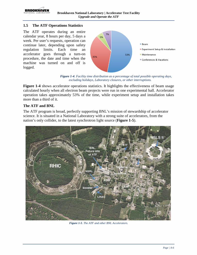
Brookhaven National Laboratory | Accelerator Test Facility Upgrade and Operate the ATF
Page | A-6
1.5 The ATF Operations Statistics The ATF operates during an entire calendar year, 8 hours per day, 5 days a week. Per user’s requests, operation can continue later, depending upon safety regulation limits. Each time an accelerator goes through a turn-on procedure, the date and time when the machine was turned on and off is logged.
Figure 1-4. Facility time distribution as a percentage of total possible operating days, excluding holidays, Laboratory closures, or other interruptions.
Figure 1-4 shows accelerator operations statistics. It highlights the effectiveness of beam usage calculated hourly when all electron beam projects were run in one experimental hall. Accelerator operation takes approximately 53% of the time, while experiment setup and installation takes more than a third of it.
The ATF and BNL The ATF program is broad, perfectly supporting BNL’s mission of stewardship of accelerator science. It is situated in a National Laboratory with a strong suite of accelerators, from the nation’s only collider, to the latest synchrotron light source (Figure 1-5).
Figure 1-5. The ATF and other BNL Accelerators.

Brookhaven National Laboratory | Accelerator Test Facility Upgrade and Operate the ATF
Page | A-7
BNL, operator of several accelerator facilities, has a global reputation for advancing the frontiers of accelerator technology and accelerator based science. Our facilities and experts are available for supporting the leading scientific endeavors of academia, industry, medicine, national security and education. Resources from the Collider-Accelerator Department Within BNL, the ATF is organizationally placed in the Accelerator R&D Division of the Collider-Accelerator Department (C-AD). Thus the ATF has the assistance of hundreds of accelerator scientists, engineers and technicians. A study of Collider-Accelerator complex upgrades to improve operational efficiency and optimize space have identified a series of projects to be implemented at BNL. Beginning with key mission critical buildings, additional studies are being performed to refine the Laboratory needs and develop time-phased implementation plans. The ATF benefits from this type of Laboratory infrastructure planning and stewardship. Leveraging the substantial infrastructure and utility systems (power, water) made available to the ATF, along with the expertise of technical trade personnel (riggers, experimental technicians, mechanics, and electricians) will advance the ATF’s mission in a way unique to BNL’s Collider-Accelerator Department.
There is no substitute for the proximity of skilled, trained technical support providing service to our users. BNL support for the ATF comes from a variety of sources such as C-AD, Information Technology, and the central shops at BNL when needed. The ATF users participate in the users’ organization called the RHIC & AGS Users Group. The ATF exclusively employs the services of the central BNL Guest, User, Visitor Center (GUV Center). The Center offers services for all User Facilities at BNL, including the Relativistic Heavy Ion Collider, the Center for Functional Nanomaterial, the National Synchrotron Light Source, the ATF, the NASA Space Research Laboratory, the Tandem Van de Graaff, and the New York Blue supercomputer. The BNL GUV Center welcomes researchers from universities, government laboratories, and industry from within the United States and abroad who are interested in visiting BNL or undertaking experiments at one of their scientific User Facilities.
Summary: The productivity of the ATF, measured in terms of new proposals, active experiments, major refereed journal publications, citation rates, and student involvement almost doubled in the last three years. The ATF is a dynamic facility, executing a continuous program of improvement in its capabilities and services, to match the requirements of an equally fast-paced community of users. An upgrade that is funded and actively progressing at the ATF will add an X-band accelerator section and deflector to assure capabilities in additional energy, waveform linearization, and the observation of ultra-fast phenomena. Another funded upgrade aims at increasing the CO2 laser power by about two orders-of-magnitude to the level of 100 TW. With the proposed upgrade, the ATF capabilities will expand in several meaningful ways. The ATF is a highly cost-effective facility, operated, maintained, and upgraded by a very small but effective staff and has been so for decades (see Figure 1-6 on the following page).

Brookhaven National Laboratory | Accelerator Test Facility Upgrade and Operate the ATF
Page | A-8
Figure 1-6. ATF current permanent staff – at a beam stop in the ATF experimental hall.

Brookhaven National Laboratory | Accelerator Test Facility Upgrade and Operate the ATF
Page | B-1
Appendix B: The ATF Present and Near Future
This page is intentionally left blank

Brookhaven National Laboratory | Accelerator Test Facility Upgrade and Operate the ATF
Page | B-2
Appendix B: Table of Contents
1.1 ATF Performance and Capabilities .............................................................................. B-3
1.1.1 Electron Beams ..................................................................................................... B-3
1.1.2 CO2 Laser Beams ................................................................................................ B-10
1.1.3 Solid State Laser Beams ..................................................................................... B-13
1.1.4 ATF Control System ........................................................................................... B-15
1.1.5 Specialized Instrumentation ................................................................................ B-24
1.2 ATF Current and Near Future Users Program ........................................................... B-32
1.2.1 Compton Scattering ............................................................................................ B-32
1.2.2 RUBICON IFEL ................................................................................................. B-36
1.2.3 Mask Technique, Capillary Discharge, and their Applications .......................... B-37
1.2.4 Ion Acceleration from Gas Jets ........................................................................... B-42
1.2.5 Attosecond Beam Characterization .................................................................... B-46
1.3 ATF Current Program of Upgrades ............................................................................ B-47
1.3.1 Electron Beam ..................................................................................................... B-47
1.3.2 X-band Deflector Cavity ..................................................................................... B-48
1.3.3 X-band Accelerator ............................................................................................. B-49
1.3.4 Photocathode Laser Driver ................................................................................. B-49

Brookhaven National Laboratory | Accelerator Test Facility Upgrade and Operate the ATF
Page | B-3
Appendix B: The ATF Present and Near Future The present status of the ATF, sophisticated and rich in capabilities, defines a lofty initial condition. The near future of the ATF can be glimpsed by observing the current set of approved and on-going experiments. Thus the ATF and its users are in the enviable position of having a lot of certainty about the future in the next few years.
1.1 ATF Performance and Capabilities As was presented earlier, the Accelerator Test Facility (ATF) is a facility that offers a high-brightness 80 MeV photocathode linac, and a high peak power picosecond CO2 laser, as well as specialized equipment and experimental floor space for research by the ATF’s users.
Figure 1-1 depicts the floor plan of the facility with its major components outlined.
Figure 1-1. ATF floor plan with key area outlines: 1- CO2 laser; 2-YAG laser; 3- electron gun, linac and
beam manipulation line (H-Line); 4 – experimental hall.
The ATF’s architecture, characteristics, and the performance of its main components are discussed in this Section.
1.1.1 Electron Beams The electron beam complex takes up the main proportion of the ATF’s floor space. It includes a photocathode gun, an S-band linac with a beam manipulation line including a chicane magnetic compressor, and experimental beam lines. These components are discussed herein.
The Laser Photocathode RF Gun A photograph of the gun is shown in Figure 1-2. It is an S-band (2.586 GHz), made of 1.6, water cooled, elliptical, copper cells, with a cavity maintained at a base pressure of ~10-10 Torr. Two ports symmetrically placed in the first 0.6 cell are used for laser irradiation and imaging of the
ATF Performance Capabilities “My personal experience at the ATF provided me the hands-on understanding of the various aspects of an accelerator laboratory, including beam dynamics studies, laser interactions, beam diagnostics, operations control, and radiation detection methods. I also have received invaluable professional guidance from senior ATF members and forged individual bonds with other students and collaborators at the ATF that have proved fruitful in my career. The ATF provides an ideal atmosphere where scientists can share their research ideas and benefit from overlapping fields of expertise.” Gerard Andonian, Ph.D., University of California Los Angeles, Department of Physics and Astronomy

Brookhaven National Laboratory | Accelerator Test Facility Upgrade and Operate the ATF
Page | B-4
cathode. One port in the full cell couples the fundamental power while the second port preserves the symmetry. RF coupling into the half-cell is through the iris.
The gun is powered by a type 4670 klystron delivering a maximum power of 10 MW, and is typically run at 2.5 MW in a 2.5 µs pulse. The design accelerating field is 100 MV/m and the corresponding peak accelerating fields and surface fields, respectively, are 130 MV/m and 160 MV/m. The combination of two solenoids, one at the exit of the gun and another at its back afford emittance compensation to the electron beam while maintaining a zero longitudinal magnetic field at the cathode.
Figure 1-2. Photoinjector Gun.
The center of the removable back flange serves as the cathode. Although typically copper is the cathode material, Mg also was used in earlier arrangements. The quantum efficiency of the laser cleaned copper cathode typically lies in the range of 0.3-0.4%, a record value. The typical operating parameters of the gun with copper cathode and best values are listed in Table 1-1.
Table 1-1. Parameters of the Gun with Cathode and Maximum Performance Values.
Parameter Typical value/range Maximum performance values Charge 0.1-1 nC 3 nC Repetition rate 1.5 Hz 10 Hz Electron spot size on cathode 2.86 mm 0.2-4 mm Bunch length 1-7 ps 100 fs w/compression Average current during pulse 70-100 A 1.5 kA w/100 fs bunch Peak current density 3 kA/mm2 Emittance 1-2 mm mrad 0.8 mm mrad @ 0.5 nC
The injector can also deliver a train of 20 pulses separated by 24.5 ns with a charge of ~ 300 pC/pulse. The ATF photoinjector was operational for nearly two decades, and was a test bed for many systematic studies to deliver high-brightness electron beams. A sampling of its unique contributions to the injector community is listed below. The early iteration of the gun was used to study nonlinear RF and space charge effects on the emittance of a high current beam [20]. Comparisons of theory and simulations to the experimental results facilitated by these studies improved the understanding of the gun’s performance. The sophisticated diagnostic system developed at the ATF to measure the low emittance [21] of these electron beams is being copied to this day. The ability to easily change the cathode in the gun supported testing of various photocathode materials, identifying copper [22] and magnesium [23] as the most suitable ones. These cathodes now are used worldwide in all the normal conducting RF injectors with metal cathodes. This feature also facilitated the testing of various techniques for inserting the cathode, and mechanisms of establishing electrical contacts that would support the high electric field gradients. The cathode’s detachable back plate with spring fingers for electrical contacts developed at the ATF is now the design commonly adopted by all S-band injectors. Laser cleaning of the photocathode and establishing conditions associated with electron emission [24] while cleaning undoubtedly has been very beneficial. Using this gun, we established a novel technique to shorten the bunch length of the electron beam [25] without magnetic compression, by changing the RF launch phase and the field in the gun.

Brookhaven National Laboratory | Accelerator Test Facility Upgrade and Operate the ATF
Page | B-5
In the final iteration, the length of the half-cell was increased to 0.6 λ, emittance compensation and bucking solenoids were installed, and the penetrations were symmetrized to reduce emittance [26]. At each stage of its development, these guns have been used as a model for several newer injectors, such as the ones in LCLS, UCLA, and Spring-8. The plans for the near future include the purchase of a new gun, which will be a LCLS equivalent gun design. Given the long lead time for the procurement, we feel it is needed for a number of reasons: Having a spare for a critical device and improved beam brightness. The procurement will be timed to enable the installation of the new gun at the new site of the ATF, thus also reducing the down-time for the transition. Linac ATF linear S-band accelerator uses two traveling wave linac sections, each 3 meters long, and are known as “SLAC sections”; both are fed by one 30 MW Triton klystron 8840 tube. Power after the klystron splits in two sections and goes through a phase shifter on one side for fine phase adjustments. Each section provides an acceleration given by 𝐸 = 10.8√𝑃 − 39.5 × 𝐼 , where E is the energy gain (in MeV), P is the RF power (in MW), and I is the beam current (in Amps). The ATF modulator can provide the klystron tube with high voltage for about 3 microseconds. This 3 μs pulse is called the macropulse. The repetition rate for them is from 1 to 6 per second. Within each of these macrobunches, we accelerate from 1 to about 200 electron bunches, or micropulses, depending on the photoinjector's laser setting. Their repetition rate is up to 81 MHz. The location of the accelerator within the electron beam complex, as well as views of the power supply components are shown in Figure 1-3.
a b c
Figure 1-3. Linear accelerator shown on the ATF floor plan, together with pictures of modulators (a), accelerator sections (b) and the klystron (c).

Brookhaven National Laboratory | Accelerator Test Facility Upgrade and Operate the ATF
Page | B-6
Beam Manipulation and Transport Line The ATF’s beam transport and manipulation line (H-line) is located directly downstream of the linac. It transports the beam from the linac to any one of the three experimental beam lines. Simultaneously, the H-line components serve for beam conditioning, configuring, and compression before entering the experimental beam lines. The H-line also is utilized for certain user experiments on beam conditioning and diagnostics. Similar to any other ATF beam lines, the H-line is well characterized and modeled as depicted in Figure 1-4.
a b
Figure 1-4. Block-diagram of the H-line (a) and its beam modeling (b).
Critical for H-line’s performance, is the magnetic chicane compressor. It consists of four dipole magnets arranged in a chicane configuration (dual dog-leg) in the vertical plane with a radiation extraction port to allow for exploitation of chicane radiation as a tool for measuring bunch length. Shown in Figure 1-4c, the ATF chicane bunch compressor is capable of reducing the electron bunch length from 1 ps to 100 fs. The chicane has been used in many experiments at the ATF including VISA, LWFA using CO2 and, more recently, the Current Filamentation Instability experiment. The chicane bunch compressor will continue to be of great value to ATF user experiments, in particular the proposed experimental study of electron beam micro bunching dynamics and shot noise suppression effect in high energy physics (see Book 2 of this proposal). Set to become an even more important asset to the ATF, the chicane will soon be complemented by a new X-band system.
Figure 1-4c. The chicane compressor installed in the H-line.
Experimental Beam Lines The H-line brings the electron beam to the experimental hall where dipole magnets distribute it in three beam lines.

Brookhaven National Laboratory | Accelerator Test Facility Upgrade and Operate the ATF
Page | B-7
The typical beam parameters are listed in Table 1-2. Table 1-2. Parameters of the electron beam.
Parameter Value/range Operational energies 30-80 MeV Beam charge typical 100pC - 1nC maximum 3nC at 90 deg gun phase at 20 μJ YAG laser routine operation 500 pC at 20 deg gun phase Bunch duration typical 1-7 psec compressed 100 fsec
Average beam current 70-100A Operational normalized emittance 1-2 mm mrad
Figure 1-5 shows the plan of the ATF experimental hall and views. The beam lines are numbered according to their position on the floor plan from top to bottom. Multiple beam lines allow spacing for several users’ experiments, facilitating rotation and reducing downtime between experiments. Each beam line is equipped with focusing and steering magnets, BPMs, and strip lines for aligning and characterizing the beam. Magnetic spectrometers at the end of beam lines 1 and 2 allow analysis the distribution of the beam’s energy. This is usually the main diagnostic for user experiments.
a
b c Figure 1-5. ATF experimental hall floor plan (a), overview (b), and a fragment of beam line 1 (c). The following components are seen, from right to left: IFEL pulsed wiggler, followed by a diagnostic box (two pneumatic actuators are seen entering the box from the left, for inserting either a phosphor screen or a He-Ne alignment laser injection mirror), followed by a beam line valve, and a quadrupole triplet thereafter. All the elements of the beam line are mounted on, and lock to dual rails for precision, ease of removal and reinstallation.

Brookhaven National Laboratory | Accelerator Test Facility Upgrade and Operate the ATF
Page | B-8
ATF Beam Line 1 This beam line previously served for the Inverse Cherenkov experiment, STELLA, PASER and plasma wakefield experiments. Presently, it is the location for experimentally probing inverse Compton scattering. For the convenience of beam line operation and for designing experiments, the beam lines are fully modeled and characterized. The beta function simulated plot and component configuration of beam line 1 are shown in Figure 1-6.
A 90-degree dipole placed at the end of beam line 1 and assembled with phosphor screen, high resolution camera and Faraday cup serves as an e-beam spectrometer to measure charge and energy distribution in the bunch. Simultaneously, it allows it to separate the electron beam from Compton X-rays that exit the beam line through a Beryllium window to the X-ray diagnostic located on an optical table after the beam line.
a b
Figure 1-6. Block-diagram of beam line 1 (a); its beam modeling (b).
ATF Beam Line 2 Previously, this beam line served for the High Gain Harmonic Generation experiment, LACARA, and the IFEL experiment. It now hosts the RUBICON, PWFA, and DWFA experiments. Beam line 2 has masked high energy slit to produce bunch trains. We plan to install an X-band RF deflector for temporal bunch sweeping in this beam line. The beta function simulated plot and component configuration of beam line 2 are shown in Figure 1-7.
a b
Figure 1-7. Block-diagram of beam line 2 (a); its beam modeling (b).

Brookhaven National Laboratory | Accelerator Test Facility Upgrade and Operate the ATF
Page | B-9
An electron beam spectrometer located at the end of beam line 2 consists of a dipole magnet, two quadrupoles, beam dump with a phosphor screen and a high resolution camera, and a Faraday cup. Quadruples are used to achieve small horizontal beta function and high dispersion at the phosphor screen for an energy resolution better than 30 keV.
ATF Beam Line 3 The ATF beam line 3 has limited use because the VISA FEL is parked there. Small scale experiments that require precise beam focusing still can be undertaken. A recent example is the Single Electron experiment conducted by a Princeton-BNL collaboration.
The ATF’s experimental beam lines are frequently upgraded to meet the demands of user experiments. Recent interest in studying dielectric wakefields in optical scale microstructures prompted the development of a new ultra-sharp focusing technique.
A 5-kG permanent quadrupole triplet assembly manufactured by Radiabeam Co. was installed within a vacuum chamber on two orthogonal stepper motor translation stages. The mini-quad triplet is shown in Figure 1-8, together with simulated electron beta functions.
a b
Figure 1-8. Permanent magnet quadrupole triplet assembly (a) and its beam modeling (b).
Figure 1-9 shows the result of an actual focal spot measurement on the OTR foil screen obtained with a 300-pC 70-MeV electron beam. The resolution of the measurement is 1.25 µm.
a b
Figure 1-9. OTR measurements of the electron beam waist. a) shows beam size in microns VS longitudinal position of the optical assembly, in arbitrary units. b) is the image of the beam spot at its waist, taken with a high resolution camera.

Brookhaven National Laboratory | Accelerator Test Facility Upgrade and Operate the ATF
Page | B-10
1.1.2 CO2 Laser Beams The ATF’s high-power picosecond CO2 laser system is positioned in dedicated interlocked laser rooms next to the experimental hall as shown in the extraction from the ATF facility’s layout in Figure 1-10.
Figure 1-10. Position of the terawatt CO2 laser system within the ATF layout.
The ATF is the only facility in the world to have a terawatt CO2 laser dedicated to user experiments. Unlike most ultrahigh-power laser systems based on solid state active media and operating at a ~1 μm wavelength. The ATF’s laser provides a powerful beam with a wavelength of 10 µm. This increase in wavelength is desirable for multiple applications, including advanced particle accelerators [27] and radiation sources based on Compton scattering [28-30].
Figure 1-11. Laser operators at the ATF CO2 laser system.
The design of the ATF’s terawatt CO2 laser is based on a modified scheme for a master oscillator – power amplifier (MOPA).
CO2 Laser Beam Highlights “The choice of the ATF for this experiment was a self-evident one. There are no other facilities in the U.S. and very few in the world which can boast a high-power laser system and a high-brightness electron beam and are accessible to outside users. The CO2 high-power laser capability is especially important for laser acceleration experiments since longer wavelength lasers are more forgiving in terms of alignment and synchronization tolerances than sub-1um laser systems.” PietroMusumeci, University of California at Los Angeles

Brookhaven National Laboratory | Accelerator Test Facility Upgrade and Operate the ATF
Page | B-11
Figure 1-12 shows the system’s simplified schematics.
Figure 1-12. Block-diagram of the ATF’s terawatt CO2 laser systems.
The rotational vibrational structure of the spectrum of the laser transition in a conventional, atmospheric pressure CO2 laser does not support using a mode locking technique for generating pulses shorter than ~1 ns. Thus, in the ATF’s system, an initial few picosecond pulse is produced by cutting a “thin slice” out of the hundred nanosecond output of a conventional CO2 oscillator via a series of fast optical switchers controlled by a short pulse solid state laser. We use semiconductor plasma switches [31]and a Kerr cell [32] to slice the pulse .
Then, a series of high pressure amplifiers boost the pulse energy. A small aperture (15 mm) regenerative amplifier, providing ~10,000 amplification, is followed by one with a large aperture (100 mm) that further amplifies the pulse ~1,000 times to multi-Joule energies. CO2 amplifiers are excited by a transverse discharge with UV pre-ionization (regenerative amplifier) and X-ray pre-ionization (final amplifier). The detailed layout of the ATF’s CO2 laser system is depicted in Figure 1-13. The ability to generate a single picosecond pulse is unique to the ATF’s CO2 laser. A common problem in amplifying picosecond 10 µm pulses is the discrete rotational line structure of the gain spectrum of the molecular gas laser amplifier.
Figure 1-13. Layout and pulse dynamics in the ATF’s CO2 laser system.
Upon amplification, the pulse’s spectrum acquires the corresponding periodic structure. In the time domain (inverse Fourier transform of the spectrum), this results in the pulse splitting into a train with a pulse-to-pulse distance equal to the inverse separation of the spectral lines (18 ps in the P, and 25 ps in the R branches).
OPTICAL SWITCHES AMPLIFIERSOSCILLATOR
Nanoseconds,kilowatts Picoseconds,
kilowatts
Picoseconds,gigawatts
Picoseconds,terawatts

Brookhaven National Laboratory | Accelerator Test Facility Upgrade and Operate the ATF
Page | B-12
The ATF applied a novel approach comprising several elements [33] for eliminating pulse splitting: (1) Operating at an R branch (λ=10.3 µm) of a laser transition having a denser line structure than a conventional P branch (λ=10.6 µm); (2) using high gas pressure (8-10 atm) in both power amplifiers to reduce spectral modulation due to collisional broadening of the rotational lines; (3) employing isotopic CO2 gas mixture, wherein the 16O atoms are partially substituted by another stable isotope, 18O in the regenerative amplifier; and, (4) utilizing the effect of spectral line broadening in strong laser field for suppressing pulse splitting in the final amplifier.
Employing an isotopic active media in the regenerative amplifier is the most innovative approach implemented recently in the ATF’s laser system.
Figure 1-14 demonstrates complete suppression of pulse splitting upon amplification.
Figure 1-14. 5-ps (FWHM) pulse amplification in a natural- (top) and isotopically enriched- (bottom) active media.
Using the ATF’s in-house developed computer code is crucial for planning a novel ultra high-power CO2 laser system. At the core of the code is the numerical solution of the equations describing interaction of a short resonant pulse with the gaseous medium of a CO2 amplifier [34]. The code also includes the pumping/relaxation dynamics of the laser levels, and Kirchhoff diffraction calculations of the pulses’ propagation through an arbitrary optical configuration, including multiple passes through the active medium.
Figure 1-15. The ATF CO2 laser system controls (to the right) and the front-end of the picoseconds pulse generator (to the left, on optical table).
The ATF offers several diagnostic tools for characterizing the picosecond 10 µm pulse.
1) The streak camera (6 ps temporal resolution) is a primary tool for monitoring the pulse-train structure. The 10 µm pulse is mixed with a 0.9 µm output of a CW diode laser in an AGS crystal to shift the wavelength into the sensitivity range of the streak camera’s photocathode.
Simulations Experiment

Brookhaven National Laboratory | Accelerator Test Facility Upgrade and Operate the ATF
Page | B-13
2) The bandwidth of a spectrum measured with a home built grating spectrometer is used to characterize the duration of individual pulses (assuming transform limited pulses). Combining the measurements from the streak camera for pulse splitting and those from the spectrometer for evaluating the duration of individual pulses offers us the way of assessing the temporal structure of the pulse in a single laser shot.
3) The single shot streak camera/spectrometer diagnostic is complemented by a multi-shot autocorrelator that utilizes the contrast of the interference pattern in a Michelson interferometer as a measure of temporal overlap of split and recombined laser pulses. With this technique, we can study the duration of individual sub-pulses, the number of sub-pulses, and the time period between them.
CO2 laser beam delivery to the user’s experiment locations comprises the following features:
• 4” diameter bare copper mirrors are used in turning points providing a 75 mm clear aperture for the laser beam.
• Switchable kinematic mirrors allow users to use either the full power beam, or an identically shaped low power beam for optical alignment purposes: The CO2 laser oscillator operating at a high-repetition rate is conveniently suited for preliminary alignment, and the regenerative amplifier for temporal synchronization or moderate energy experiments.
• An active semiconductor (Si wafer) switch controlled by a dedicated Q-switched nanosecond Nd:YAG laser assures optical isolation of the laser system from plasma back reflection produced at the laser focus (relevant primarily for ion acceleration experiment).
• Placing most of the transport line inside beam enclosures, and laser beam shutters integrated into the facility interlock system, together with PPE, mitigate the risk of the personnel injury.
1.1.3 Solid State Laser Beams Strong field experiment laser As the requirements of the facility have evolved, the need to provide diverse laser sources has become more important. In order to extend the range of experiments and allow near-IR interactions in the range of a0~1-3 at near-IR wavelengths complementary to the capabilities of the CO2 laser, a Ti:sapphire laser system capable of peak power from 1-10 TW will be added to the list of the ATF’s research tools. The system will be seeded by the phase locked output of an existing Ti:sapphire laser now being commissioned for the photoinjector. A fraction of the recompressed pulse normally used for UV conversion will undergo cross polarization wave (XPW) filtering before normal CPA. This dual XPW CPA scheme will provide the high peak power and contrast required for strong field interaction experiments with foil as well as plasma and free electron targets.
A particularly elegant example of the unique capability such a laser would afford is a proposed two-color Compton scattering experiment [35]. By relying on lasers at two different frequencies, the resulting X-Ray spectrum can be tailored to achieve optimal spectral brightness for novel applications.
Nearly all components required to achieve 1TW are currently available for integration, except the XPW filter, which has been well studied [36]. A 1 TW amplifier system has been tested with a standalone seed oscillator at BNL’s Instrumentation Division. Relocation to a common laser

Brookhaven National Laboratory | Accelerator Test Facility Upgrade and Operate the ATF
Page | B-14
room and integration with the new Ti:sapphire photocathode laser will be required once space becomes available. To increase peak power to 10 TW, additional amplifier stages and a compressor vacuum chamber will be required. This is currently planned to coincide with the upgrade of the linac to 500 MeV.
Photoinjector driver secondary beams In addition to driving the photocathode and CO2 slicing systems, the Nd:YAG photocathode laser provides synchronized short optical pulses for other purposes.
Low power pulses mimic the time structure of optical transition radiation or other emission sources based on the electron beam, and may therefore serve as reliable calibration, test, or alignment aids to experiments installing complex detection systems.
Similarly, high speed detectors such as photodiodes, streak cameras, and optical correlators may benefit from an optical source intrinsically phase locked to the electron or CO2 laser beams. By providing a timing fiducial, systematic errors may be analyzed and removed.
Higher energy pulses may be used directly as a diagnostic probe beam with picosecond time resolution. An example of this is the Ion Generation Experiment plasma interferometry measurement with a frequency doubled pulse. This probe pulse from the Nd:YAG laser allows very high temporal and spatial resolution to be achieved.
Further amplification stages may increase the peak power to levels useful for interaction experiments. The IGS experiment utilized such a pulse at a peak power of 10GW, a capability still available for other experiments.
Beam transport paths to experimental areas Laser transport paths have been established to all experimental areas of the facility. Delivery of YAG laser IR pulses is currently possible in all rooms except the gun hutch, where only UV is necessary. Additionally, frequency doubled and –quadrupled pulses are available in a few areas. Output of the Ti:sapphire lasers is now also available in the experimental rooms, and is currently in use.
The laser personnel protection system has been engineered to control Class-4 laser hazards in all areas, and is able to accommodate beam delivery between rooms while allowing personnel to move freely between rooms without interrupting operations.

Brookhaven National Laboratory | Accelerator Test Facility Upgrade and Operate the ATF
Page | B-15
1.1.4 ATF Control System Introduction The ATF control system will be used to monitor, control, automate and notify both operators and users of most aspects of the facility's research subsystems. It must be designed and implemented in such a way that all capabilities of the current ATF control system, which users have come to expect, will also be available during and following the upgrade. Plans must account for potential expansion of the facility and be able to accommodate the inevitable improvements expected in technology.
The following sections present a brief review of ATF control system history, describe the current system, summarize plans for near future upgrades and conclude with some final remarks.
Some Background History and Perspectives By reviewing some historical actions related to the present ATF control system, important perspectives useful for evaluating the proposed new control system can be identified. These perspectives underscore several key success themes: (i) Recognition and application of a unified system development framework, (ii) Careful practice of software engineering design principles to avoid “lock-in” situations and (iii) Obtaining prebuilt, pretested hardware and software whenever possible, focusing in-house efforts on only those items unavailable elsewhere.
From its earliest days (c. 1988), well before formal commissioning, ATF staff understood the need for a modern, modular, reliable and extensible control system framework. Due to limitations in both funds and staffing, it was acknowledged that in-house development of such a system would be impossible. After some searching and evaluations, ATF eventually obtained a copy of the control system software tools used at the Ground Test Accelerator, located at Los Alamos National Laboratory. A short time later, the software became available as a commercial product (Vsystem) [37] marketed by Vista Control Systems, Inc. under a DOE supported technology transfer agreement. ATF recognized the power in the unified tools which included a database generator, a drawing package to construct graphic user interfaces (GUIs), alarm handlers, data archiving and recall tools, among others. The central (and vital) idea which unified all the tools was the concept of a client server, network-based architecture with the so called “channel access” communications protocol. ATF adopted Vsystem [38] and abstracted the channel access protocol and has used it for the life of the facility. EPICS [39], the open source control system framework proposed for the evolution of the ATF system, uses an analogous tool
The Accelerator Test Facility and its Control System Highlights • The ATF control system has a demonstrated record of providing
reliable service to its users for more than 20 years. Continuous evolution and refinement have made it highly attuned to the needs of a dedicated accelerator physics user facility. Its creativity has been recognized by the scientific community.
• Key design philosophies and adherence to established software
engineering practices enabled past migration efforts to introduce major new hardware and software systems successfully with no negative impacts to the experimental program. Continued development for the ATF will capitalize on these successful methods and experiences.
• Valuable ATF control system institutional knowledge will be preserved and leveraged in planned upgrades with little need required for retraining of operating personnel. Present ATF capabilities, which users have come to expect, will be carried forward.
• Adoption of the de facto standard Experimental Physics and Industrial Control System (EPICS) framework will assure a very high probability of success.

Brookhaven National Laboratory | Accelerator Test Facility Upgrade and Operate the ATF
Page | B-16
set also unified by channel access. Thus, ATF staff members are already familiar with the core constructs of EPICS having many years of experience working with a conceptually similar framework.
The Vsystem and EPICS packages referenced above are excellent development frameworks but are not turnkey systems, therefore development of facility specific databases, tools, or applications is usually required. As with any third party hardware or software, it is easy to become “locked in” to a particular package, vendor or other provider. It is incumbent on developers to avoid these situations by isolating and abstracting the provider specific details. ATF has followed this defensive practice and built all its application programs using in-house libraries that isolate and concentrate these dependencies. High level applications never call provider functions directly, instead calling these intermediate level libraries which hide the details of the lower level activities. As such, many current ATF applications will port from Vsystem to EPICS with the only requirement being to re-write the intermediate libraries and to recompile and re-link the applications.
The abstraction principle mentioned above has been applied in an even larger scope. During its first decade, the ATF control system operated on VAX computer hardware running the VMS operating system. Applications programs were written in Fortran. Data acquisition was through CAMAC hardware communicating over a byte serial highway. By again abstracting all these dependencies into special libraries, the ATF was able to avoid lock-in and in 2004 completed a complete migration [40] to Intel hardware running Linux, rewriting all the applications in C++ and moving to completely network-based communications. The power of the ATF abstractions transcended wholesale changes in processor hardware, operating system, programming language and communications medium. Similar defensive practices will be followed when implementing the planned evolution of the ATF control system.
Current ATF Control System The current ATF computer control system is the product of more than 20 years of experience in the development of control and data acquisition systems to support the needs of a user facility dedicated to accelerator physics research.
It was designed by accelerator specialists, for accelerator specialists. The system is depicted schematically in Figure 1-16.
Figure 1-16. Schematic Diagram of Present ATF Control System.
CAMAC-Interfaced Equipment
Operator Workstat ion, PC or Other Clients
Contro l System Main Host
LAN
Network-Interfaced Equipment

Brookhaven National Laboratory | Accelerator Test Facility Upgrade and Operate the ATF
Page | B-17
Controlled devices shown in Table 1-3, include the usual portfolio of equipment in an accelerator facility, including:
Table 1-3. Controlled Devices. • RF system • Video signal switching • Injection laser • Timing system • Stepper motors and motorized stages • Trigger switching and routing • TTL/contact inputs and outputs • Magnet power supplies • Joulemeters • Faraday cups • Laser flippers • Stripline monitors • 8 independent video frame grabbers with independent
triggering • Pop-in and beam position monitors
• RS-170 analog, Basler GigE and Princeton Instruments cameras
• Vacuum system
• Oscilloscopes • Serial and GPIB interfaced devices • Other network-capable devices Data acquisition devices can be triggered by facility events that are typically the linac repetition rate clock (1.5, 3 or 6 Hz), firing of the CO2 laser, a 10Hz fast trigger or a user-supplied trigger. Due to the switching and fan-out capabilities, arbitrary triggers offset from standard facility events can also be used.
Channels in the database contain state information as to pending or current events such as “linac rep rate clock has just incremented”, “data collection in progress”, “data collection is finished and database is ready for reading”, “a new pulse is imminent”, “the rep rate clock has stopped unexpectedly”, etc. Figure 1-17. shows the ATF video frame grabber system.
Most all of the equipment needed for operations or experiments is accessible through the control system. Users can access the facility devices in one of two ways: (i) by using a point and click graphical user interface consisting of more than 900 display windows or (ii) direct access to the underlying real-time databases. The GUI replicates the physical layout of ATF beam lines so most users find it easy to navigate with little training. Users and ATF staff all share the same GUI and tools so assistance is always available. A typical operator window is shown in Figure 1-18.

Brookhaven National Laboratory | Accelerator Test Facility Upgrade and Operate the ATF
Page | B-18
Figure 1-18. Sample operator display illustrating graphic control tool elements.
Beyond the ATF GUI, any control element visible in an operator display has a corresponding channel entry in a database and can, once authorized, be accessed from network clients other than the ATF GUI itself. Such clients have been written to use C/C++, LabViewTM, MatlabTM, MathematicaTM, MathcadTM, Expect, and Bash, among others. These specialized clients are typically used to automate tasks by scripting complex procedures for jobs such as beam setup and optimization, machine status reports and data collection for complex experiments.
The control system can exploit the power of these external packages, especially their strengths in data management, graphics, statistics, numerical analysis and report generation. Some typical screen captures are show in Figure 1-19 and Figure 1-20. ATF's novel use of Mathcad in this fashion was profiled in the April 2001 cover story of Scientific Computing and Instrumentation (Figure 1-21) [41]. Workstations that can access the GUI and/or specialized clients are located in the main control room, the mezzanine area, the experiment hall and the laser areas. Approved and trained users also have the option of connecting their own computing equipment to the private ATF local area network.

Brookhaven National Laboratory | Accelerator Test Facility Upgrade and Operate the ATF
Page | B-19
Figure 1-19. Sample script showing facility operating conditions.

Brookhaven National Laboratory | Accelerator Test Facility Upgrade and Operate the ATF
Page | B-20
Figure 1-20. Sample script showing data acquisition, calculations and graphical presentation.

Brookhaven National Laboratory | Accelerator Test Facility Upgrade and Operate the ATF
Page | B-21
Figure 1-21. April 2001 cover of Scientific Computing and Instrumentation;
© Cahners Business Information. Used by permission.
The control system provides other tools to assist operators and users: alarm handling and display; snapshot and restore utilities to capture and re-establish operating conditions; x/y and strip charts for plotting; plus archival/replay tools for synoptic data. Most of all of the information collected at the ATF is available for users to download and retain on their personal media, usually as ASCII data files.
Planned Near Term Control System The plans for the near term ATF control system upgrade consist of a number of upgrades, all of which are driven by these main goals: (i) increase user productivity and (ii) establish stable and reliable systems with long term viability and upgrade paths. It should be noted that while many of these upgrades entail major changes, none will require elimination of any present ATF capabilities which users have come to expect.

Brookhaven National Laboratory | Accelerator Test Facility Upgrade and Operate the ATF
Page | B-22
The planned system topology is shown schematically in Figure 1-22. It is a straightforward, two-layer architecture where top-level clients communicate with lower equipment through input-output controllers (IOCs) in VME crates or through devices with channel access built in, i.e., essentially a virtual IOC.
Figure 1-22. Schematic Representation of Proposed Evolution of the ATF Control System.
The number of GUI displays will be not change appreciably in the foreseeable future, while the number of I/O channels is projected to grow by about 20%.
Major items in the upgrade are:
• Main control room: One area where users will see a marked difference following the proposed relocation will be in the main control room. The new control room will be an open area able to comfortably accommodate at least 6-8 users, up from the present 2-3 (Figure 1-23). Supporting equipment which, at present, must share space in the ATF control room will be moved to an adjacent equipment room making the new control room a comparatively much quieter area.
Figure 1-23. Present ATF Control Room (Marcus Babzien is standing next to Robert Malone, Karl Kusche, and Mikhail Fedurin-back to front).
Main Cluster withExternal Storage
SAN
VME-Interfaced Equipment
Workstations or Other Clients
LAN
Network-Interfaced Equipment

Brookhaven National Laboratory | Accelerator Test Facility Upgrade and Operate the ATF
Page | B-23
• EPICS: The de facto control system tools framework in use at many accelerator facilities. It has a large user base that has developed and shared many software tools and device drivers, including BNL’s NSLS-II project - a major source of local expertise. A similar GUI to that used at the current ATF system will be developed. Database clients in use at ATF will need to be ported, but the common channel access conceptualization will be helpful. Using EPICS to construct operator displays and client applications similar to those at ATF should help operating personnel manage the changeover to the new system.
• VME hardware: CAMAC hardware will be gradually replaced by VME hardware and crates controlled by single board computers (SBCs) acting as EPICS input/output controllers (IOCs). This is a common design among many other accelerator facilities.
• Main computer cluster: This will be the primary development system as well as the boot server for the SBCs located in the VME crates. The cluster configuration allows for a fail-over host to be online and available to continue operations should the main host fail. The cluster also acts as the main storage location for data collected from user experiments. For example, all frame grabbers will store their recorded images on this central system. The cluster will also act as an EPICS client for those experimenters who don't have a client installed on their own computers.
• Storage Area Network (SAN): While each of the cluster computers will have its own operating system disks, a storage area network will avoid “trapped data syndrome”, a condition in which a host fails and all its files remain unavailable because they are stored internally. By externalizing critical files to the SAN, the standby cluster host can continue operations using the external files.
• Magnet power supplies: A new modular power supply system (Figure 1-24) with completely digital control via network interface will be used to drive magnetic optics components. Beam stability should increase due to the lack of noise pick-up which can occur when using analog control and readback lines. EPICS channel access compatibility is built in.
Figure 1-24. Modular power supply system.
• Timing system: A new timing generation and distribution system manufactured by Micro Research will be implemented, replacing the DG535 digital delay generators presently in use.
Many of these proposed improvements are already being tested on a small scale at the ATF, increasing confidence that implementation will succeed.
Conclusion With more than 20 years of experience in developing and operating a control system for an accelerator physics user facility, we have a solid understanding of the needs of our users, gives strong confidence that challenges will be met and that a new facility will emerge, fully prepared to serve the community for many years.
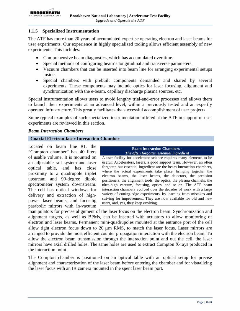
Brookhaven National Laboratory | Accelerator Test Facility Upgrade and Operate the ATF
Page | B-24
1.1.5 Specialized Instrumentation The ATF has more than 20 years of accumulated expertise operating electron and laser beams for user experiments. Our experience in highly specialized tooling allows efficient assembly of new experiments. This includes:
• Comprehensive beam diagnostics, which has accumulated over time. • Special methods of configuring beam’s longitudinal and transverse parameters. • Vacuum chambers that can be inserted into beam line for arranging experimental setups
inside. • Special chambers with prebuilt components demanded and shared by several
experiments. These components may include optics for laser focusing, alignment and synchronization with the e-beam, capillary discharge plasma sources, etc.
Special instrumentation allows users to avoid lengthy trial-and-error processes and allows them to launch their experiments at an advanced level, within a previously tested and an expertly operated infrastructure. This greatly facilitates the successful accomplishment of user projects.
Some typical examples of such specialized instrumentation offered at the ATF in support of user experiments are reviewed in this section.
Beam Interaction Chambers Coaxial Electron-laser Interaction Chamber
Located on beam line #1, the “Compton chamber” has 40 liters of usable volume. It is mounted on an adjustable rail system and laser optical table, and has close proximity to a quadrupole triplet upstream and 90-degree dipole spectrometer system downstream. The cell has optical windows for delivery and extraction of high-power laser beams, and focusing parabolic mirrors with in-vacuum manipulators for precise alignment of the laser focus on the electron beam. Synchronization and alignment targets, as well as BPMs, can be inserted with actuators to allow monitoring of electron and laser beams. Permanent mini-quadrupoles mounted at the entrance port of the cell allow tight electron focus down to 20 µm RMS, to match the laser focus. Laser mirrors are arranged to provide the most efficient counter propagation interaction with the electron beam. To allow the electron beam transmission through the interaction point and out the cell, the laser mirrors have axial drilled holes. The same holes are used to extract Compton X-rays produced in the interaction point.
The Compton chamber is positioned on an optical table with an optical setup for precise alignment and characterization of the laser beam before entering the chamber and for visualizing the laser focus with an IR camera mounted in the spent laser beam port.
Beam Interaction Chambers - The often forgotten essential ingredient
A user facility for accelerator science requires many elements to be useful: Accelerators, lasers, a good support team. However, an often forgotten but essential ingredient are the beam interaction chambers, where the actual experiments take place, bringing together the electron beams, the laser beams, the detectors, the precision positioners, the alignment tools, the optics, the plasma channels, the ultra-high vacuum, focusing, optics, and so on. The ATF beam interaction chambers evolved over the decades of work with a large variety of cutting-edge experiments, by learning from mistakes and striving for improvement. They are now available for old and new users, and, yes, they keep evolving.

Brookhaven National Laboratory | Accelerator Test Facility Upgrade and Operate the ATF
Page | B-25
The standardized chamber and optical setup, which has been perfected over a series of experiments, allows fast and efficient transition to any new experiment that requires the interaction of tight focused laser and electron beams.
Although traditionally called “Compton chamber” (Figure 1-25), the cell allows reversal of the laser direction for co-propagation with the e-beam to explore mechanisms of laser acceleration. Hosted experiments include: AE22 Inverse Compton Scattering, AE27 Vacuum Laser Acceleration (VLA), and AE31 Current Filamentation Instability (CFI).
Figure 1-25. Coaxial Electron-laser Interaction Chamber.
Primary operational features include:
• Large central volume and top flange with multi-axis translation stage accommodate interaction targets and beam diagnostics, side ports for laser windows (accommodates up to 3” diameter CO2 laser beam), top and side ports for 3-axis mirror mounts with translation actuators.
• Beam profile monitors at interaction region as well as chamber entrance and exit. • Available port for 200 l/s turbo pump. Operates in the 10-8 Torr range.
Electron-plasma Interaction Chamber Located on beam line #2, the “Plasma chamber” (Figure 1-26) has 80 liters of usable volume. It is mounted on an adjustable platform and optical table, and has close proximity to a quadrupole triplet upstream and 20-degree dipole spectrometer system downstream. Hosted experiments include AE31 Plasma Wakefield Acceleration (PWFA), AE50 Quasi-Nonlinear PWFA, AE39 Dielectric Wakefield Acceleration (DWFA), AE43 PWFA Holography, and AE49 Coherent Terahertz (THz) Radiation.
Figure 1-26. Electron Plasma Interaction Chamber.

Brookhaven National Laboratory | Accelerator Test Facility Upgrade and Operate the ATF
Page | B-26
Primary operational features include:
• Easily removable lid with multiple flanges for windows & electrical feed through(s), large internal area with breadboard for mounting a variety of interaction targets and beam diagnostics, accommodates 5-axis plasma capillary discharge assembly (large flange).
• Beam profile monitors at interaction region as well as chamber entrance and exit. • Dedicated 500 l/s turbo pump and one auxiliary 200 l/s turbo pump port. Normally
operates in the 10-8 Torr range, but allows for rapid one hour turn-around time (achieves 10-6 Torr range) when used with thin film pellicle inserted upstream.
• Discharge assembly mounted on 10” Conflat flange with multiple feed through(s) for high voltage, gas input and fiber optics.
• Electron beam input flange can accommodate multi-axis motorized drivers connected to miniaturized electron beam focusing magnets within the chamber.
The capillary discharge development is addressed in Appendix C. Picture of the capillary discharge setup is shown in Figure 1-27. The setup has the following main features:
• Insulated Macor capillaries, 1 mm diameter, implanted fiber optics for plasma diagnostic.
• Remotely triggerable 15 kVDC discharge and gas burst, synchronized to the electron beam.
• A variety of gases, including hydrogen and helium. • Remotely controllable 5-axis mounts, with fiber optic
diagnostic feed through(s). Figure 1-27. Capillary discharge assembly.
Plasma Density Diagnostic Two techniques have been developed by ATF experimenters to characterize the time evolution of plasma density in the capillary channels that have routinely been used for studies of electron/laser/plasma interaction. The capillary typically used is a 5-10 mm long, 1 mm ID ceramic channel with end electrodes. Hydrogen gas injected into the capillary is ionized by a longitudinal electrical discharge. Plasma densities up to 1019 cm-3 have been produced.
The first diagnostic allows for precise control of the plasma density at the time of interaction by measuring the rate of decay of density following termination of the electrical discharge. Plasma density evolution is very repeatable and is then adjusted simply by controlling the amount of time between electrical discharge and interaction process. The diagnostic relies on spectral measurement of the Hα emission that experiences Stark broadening in the plasma [42]. The Hα emission is collected from the central portion of the capillary by an optical fiber inserted through the sidewall and transported to photomultiplier tubes through narrowband spectral filters. The ratio of intensity at different wavelengths is then calculated to determine the amount of line broadening. In this way the exponential decay of plasma density is verified for each capillary configuration in order to produce the desired mapping from delay to density.
The second diagnostic enables measurement of plasma wakefields on the picosecond timescale using ultrafast optical probe pulses. Although in this frequency domain interferometry has yet to

Brookhaven National Laboratory | Accelerator Test Facility Upgrade and Operate the ATF
Page | B-27
be completed at ATF, it has been demonstrated experimentally elsewhere [43]. Two optical pulses originate from a Ti:sapphire laser, and are separated in time by several picoseconds. The pulses are synchronized such that the first traverses the plasma channel before the wakefields are generated, and the second immediately after. The pulses are combined downstream in an optical spectrometer, where the different spectral components interfere. The resulting interference fringes can be analyzed and the density profile of the wakefields determined by scanning the time between pulses. This method also allows some spatial information to be recovered transverse to the capillary axis. A single shot extension of this technique known as frequency domain holography requires chirped pulses, and is also possible under ATF conditions.
Dielectric Wakefield Acceleration (DWFA) Chamber Located on beam line #1, the “DWFA chamber” (Figure 1-28) has 160 liters of usable volume. Due to its size, it is mounted on a fixed platform. Hosted experiments include AE40 Inverse Gamma Source (IGS), AE39 Dielectric Wakefield Acceleration (DWFA), and Surface Wave Accelerator and Radiation Source Based on Silicon Carbide (SWABSiC).
Figure 1-28. DWFA Chamber.
Primary operational features include:
• Easily removable lid, multiple flanges for windows & electrical feed through(s) for in-vacuum motorized stages & translators, large internal area with breadboard for mounting a variety of interaction targets, beam diagnostics and miniaturized electron beam focusing and steering magnets.
• Beam profile monitors at interaction region as well as chamber entrance and exit.
• Dedicated ion pumps (250 l/s total) with a port for one 200 l/s turbo pump. Operates in the 10-
8 Torr range. Figure 1-29. Permanent Magnet quadrupole assembly and
OTR BPM with enhanced resolution optical system and mirrors mounted on translation stages in the DWFA chamber.

Brookhaven National Laboratory | Accelerator Test Facility Upgrade and Operate the ATF
Page | B-28
The chamber has a removable top cover to allow easy access to assemble flexible and complex in-vacuum experiment setups on a breadboard. The setups usually include magnets, mirrors, and waveguide structures mounted on multi-axis translation and rotation stages with stepper motor controls. Multiple ports serve connections to the beam line, electrical feed through(s), and viewports and radiation extraction.
In recent experiments shown in Figure 1-30, assemblies of the permanent quadrupole and dipole magnets were mounted on translation stages in order to retract them from the beam axis to allow default beam optic configuration and alignment. Dielectric structures were also mounted on stages together with phosphor screens to make possible the fine beam alignment and full beam transmission through the tiny micron scale structures. The chamber is equipped with a two position beam profile monitor, where YAG crystal is used as a default and the OTR foil for micron size beam profile measurements. Figure 1-30. Dielectric capillaries mounted on two-axis rotation- and translation- stages. Transverse position stage
defines which capillary is inserted into the e-beam. Phosphor screens at front and back of the capillaries help to align them on the beam. The capillary setup is separated by magnetic screen from the chicane assembly downstream.
Laser Injection Vacuum Chamber Located on beam line #1, the “Smith-Purcell box” (Figure 1-31) has 140 liters of usable volume. Due to its size, it is mounted on a fixed platform. Hosted experiments include AE13 Smith-Purcell effect, AE03 Laser Grating Accelerator, AE20 Staged Electron Laser Acceleration (STELLA), and AE02 Inverse Free Electron Laser accelerator (IFEL).
Figure 1-31. Laser Injection Vacuum Chamber.

Brookhaven National Laboratory | Accelerator Test Facility Upgrade and Operate the ATF
Page | B-29
Primary operational features include:
• Removable lid with single large laser input window (able to accommodate up to 6” diameter CO2 laser beam), multiple flanges for windows & electrical feed through(s).
• Large internal volume and mounting surface for laser optics. • Dedicated 500 l/s ion pump and one 200 l/s turbo pump auxiliary port. • Operates in the 10-8 Torr range.
Ion Generation Vacuum Vessel The “Ion Generation vessel”, located in the CO2 laser area (Figure 1-32), has 100 liters of usable volume. Hosted experiment - AE35 High-brightness picosecond ion beam source.
Figure 1-32. Ion Generation Vacuum Vessel.
The chamber, designed specifically for this experiment, has dedicated optical windows for delivering and extracting a high-power CO2 laser beam and an optical probe beam, as well as additional optical ports for a He-Ne alignment beam. It also has a view-port for an enhanced CCD camera pointed to a luminescent screen of a Thomson parabola spectrometer for measuring the ion energy. In addition to the spectrometer, and a supersonic gas nozzle CO2 laser reflective optics are mounted on an optical breadboard floor inside the chamber. The gas jet and laser focusing mirror are equipped with in-vacuum manipulators for exact positioning of the laser focus onto the gas jet.
Primary operational features include:
• Removable lid, multiple flanges for laser windows & electrical feed through(s) for in-vacuum motorized stages & translators, large internal area with breadboard for mounting a variety of interaction targets and beam diagnostics.
• Accommodates gas feed through(s) and in-vacuum gas jet system. • Dedicated 300 l/s turbopump system with an auxiliary port for one 200 l/s turbo pump.
Operates in the 10-6 Torr range with rapid one hour turn-around time. Vacuum recovery time between the gas jet shots – 30 seconds.

Brookhaven National Laboratory | Accelerator Test Facility Upgrade and Operate the ATF
Page | B-30
Diagnostic Tools Semiconductor switch laser/electron synchronization Using the transient electron hole plasma generated in a semiconductor during the transit of the electron bunch, the arrival time of an optical probe pulse may be synchronized to the electron bunch. This has been demonstrated and used for CO2 laser pulses and is now being tested at near-IR wavelengths. The plasma density in the semiconductor decays with a characteristic time constant of a few hundred picoseconds. By measuring the transmitted optical pulse that is absorbed within this time, an efficient binary search in relative delay is possible, allowing for rapid synchronization after coarse adjustments with only a photo-detector and oscilloscope.
Sub-10 µm resolution BPM Several classes of experiments require delivery of miniature electron beams, and the ATF is well suited to produce such beams because of the low emittance from the photoinjector. However, measuring such beams is not trivial, therefore this capability has been developed as more user experiments have demanded micron-size beams. The ATF approach to measuring the shape and size of such beams relies on transition radiation, which has a much better intrinsic resolution than phosphor or scintillator-based sources, and produces sufficient number of photons to be detected by high resolution CCD cameras. In order to achieve optical resolution of a few microns, a microscope objective is placed downstream of a metal foil in-vacuum. The foil radiates optical transition radiation forward into the acceptance angle of the all reflective objective, which collimates the emission with negligible chromatic or spherical aberration. The emission is reflected out of the vacuum chamber through a window and focused into a CCD camera at the desired magnification. This system has been used to achieve better than 4 micron resolution, and is compatible with vacuum levels of 10-7Torr.
Cryogenic IR Bolometer
• Dual silicon bolometer system (model HDL-5, Infrared Laboratories) with wedged polyethylene IR windows
• Covers far-IR wavelengths from 10 microns to beyond 200 microns • Liquid helium cooled for low noise and pre-amplification for high sensitivity • Used in conjunction with Bunch Length Interferometer System (BLIS, Radiabeam
Technologies) for sub-picosecond electron bunch analysis
Cooled IR detectors
• HgCdTe detector elements, liquid nitrogen cooled • Covers IR wavelengths 1-10 micron, complementing IR bolometer range
X-ray detectors
• Silicon chip circuit, covers X-ray energy range 2-20 keV • Shad-o-Snap (model 1024, Radi-con Imaging Corp.), large area X-ray camera with USB
interface, covers X-ray energy range 10-50 keV
Brookhaven National Laboratory | Accelerator Test Facility Upgrade and Operate the ATF
Page | B-31
Streak camera A standard electrostatic Hamamatsu streak camera is available with a temporal resolution of 10ps, visible wavelength sensitive photocathode, and an imaged entrance slit for spatially resolved measurements. The 10 µm radiation is converted to the spectral region of the streak camera by mixing picoseconds CO2 laser pulses with a quasi-CW laser diode on a non-linear crystal. This process preserves the time structure of the picosecond pulse allowing meaningful temporal characterization of laser pulses. A new camera with a 1.5ps temporal resolution is to be acquired shortly.
Spectrometers A 270cm Czerny-Turner imaging spectrometer with gratings covering visible, near and mid-IR wavelengths is moved between different areas as needed. A variety of CCD, PMT, thermal and pyroelectric detectors are available for coupling to the dual output ports.
A multi-channel fiber-coupled visible/NIR spectrometer with integrated CCD array and readout provides digitized spectra. Current channels available cover 340-1020nm and 910-1150nm. Both channels have better than 0.5nm resolution, and additional channels may be added.
800 & 1000 nm FROG Two frequency resolved optical gating (FROG) instruments are available covering the 800 and 1000nm spectral ranges. Pulse width range is 50-500fs at 800nm, and 200-2000fs at 1000nm.
Fast photodetectors Several photo-detectors with bandwidths >1GHz covering the wavelength range from UV to 1.5 micron as well as mid-IR are available. Coupled to multi-GHz oscilloscopes, they are routinely used to record high speed optical phenomena.
Infrared/Terahertz interferometer Two liquid helium cooled bolometers are available, one of which may be coupled to a Michelson interferometer to measure optical autocorrelations. Spectral range is from mid-IR to mm-wave, and is ideally matched to measure the temporal structure of sub-picosecond electron bunches via transition radiation.

Brookhaven National Laboratory | Accelerator Test Facility Upgrade and Operate the ATF
Page | B-32
1.2 ATF Current and Near Future Users Program With over fourteen active experiments and three Feasibility Studies in its portfolio at present, the ATF’s user program has a depth and diversity as never before. The quality of the research has much improved and the volume of results has escalated following our continuing upgrades of equipment and accumulation of new research capabilities.
The ATF’s aggressive program of upgrading the CO2 laser now allows us to explore the effects in strong field physics. Bright examples of the ongoing progress in the laser-driven research are our very recent observations, obtained in the beginning of 2013, on higher harmonics in nonlinear inverse Compton scattering, and record-high IFEL acceleration gradient, as well as the absolute gain in energy achieved in the RUBICON experiment. The ion acceleration experiment is another direct beneficiary from the laser upgrade program, due to the linear proportion of the maximum ion beam energy to the laser intensity.
Another resource for the continuing progress in user research programs is the synergy between the generations of experiments, where the most successful methods and technologies become permanent assets to enable new scientific endeavors. Examples of such research tools that have been perfected at the ATF and add now to its program diversity are the techniques of capillary-discharge plasma source and micro-bunch generation.
All these categories of user experiments reviewed here are very actively pursued at present and build the foundation for dynamic progress in the near future.
1.2.1 Compton Scattering Supporting a user research program on inverse Compton scattering (ICS) has remained one of the ATF’s primary occupations for the last 15 years. The continuing interest in undertaking ICS research at the ATF is founded upon the proven advantages of radiation from the long wavelength CO2 laser towards achieving the best yield and quality of the X-ray beam (see Appendix C), as well as by the on-going laser upgrades that bring the ICS research to new levels of performance. From among several such researches, two are highlighted below. They include a yet unpublished pioneering demonstration of high order relativistic effects, and an upcoming new experiment on high average power ICS where the laser/e-beam interaction is set inside the laser’s recirculation cavity.
Nonlinear effects in ICS The Principal Investigator (PI) for Nonlinear ICS is J. Rosenzweig, UCLA The recent improvements in the ATF’s CO2 laser, in particular, using CO2 isotopes for the picosecond pulse amplifier, allowed us to attain a single pulse regime in excess of 1 TW peak power. This upgrade led to a revival of the interest in fundamental studies of the higher order nonlinear effects in ICS that are related to the electrons’ quiver motion at relativistically high laser intensities. The experiment carried out by researchers and students from UCLA’s Physics
Current Experiment on Dielectric Wakefield Acceleration “The studies on dielectric wakefield acceleration are particularly relevant in the advanced accelerator community. These groundbreaking results from the UCLA/ATF collaboration demonstrate the proof-of principle for accelerating electron bunches, resonant excitation of higher-order modes, and field characterization in both cylindrical and planar geometries. The ATF is the only facility that can readily deliver the beam requirements, such as low emittance, variable bunch train generation and optimization, with a complete suite of diagnostics, which was necessary for these measurements. Indeed our program continues at the ATF with further studies on structures with 1-D and 3-D photonic-style boundaries for enhanced modal confinement, with exciting preliminary results.” Letter from Gerard Andonian, UCLA

Brookhaven National Laboratory | Accelerator Test Facility Upgrade and Operate the ATF
Page | B-33
Dept. provided the first demonstration of the laser induced mass shift effect in the ICS spectrum. As illustrated by Figure 1-33, the shift in the fundamental high energy edge of the spectrum, ℎ𝜔𝑚𝑎𝑥′ = 4𝑛ℎ𝜔𝐸2
𝑚�2𝑐4+4𝑛ℎ𝜔𝐸, is due to the change in effective electron mass 𝑚� = 𝑚�1 + 𝑎02
caused by a relativistically strong laser beam characterized by the normalized laser strength parameter 𝑎02 = 3.7 × 10⁻¹⁹𝐼𝜆2, for I in Watts/cm2 and λ in µm.
This shift was revealed by filtering out the high energy portion of the spectrum using a carefully selected combination of the K-edge absorption filter and the e-beam’s energy. A central dip in the angular ICS distribution visible at the relatively low laser intensity a0 << 1 (see right color pattern on Figure 1-33) disappears at the increased intensity, a0 ~ 1 (left pattern). The method allows estimations of the laser strength parameter a0 that proved to be ~0.75. Figure 1-33. Demonstration of mass-shift effect in the ICS spectrum; left plot – simulated spectra; color profiles to the right are x-ray angle distributions experimentally observed with MCP.
By filtering out the high energy portions of the ICS spectrum, the experiment demonstrated higher X-ray harmonics with a never previously afforded extent and clarity. Figure 1-34 shows the observed angular distributions for different harmonics compared with simulations for idealized conditions (such as zero emittance, and zero energy spread). Characteristic multiple lobes are clearly visible on experimental images. The experiment will progress with incorporating the X-ray spectrometer and towards investigating “multi-color” action of the laser (combined 10 µm and 1 µm beams).
Figure 1-34. Observed fundamental, 2nd, and 3rd harmonics (from left to right at the bottom) compared to simulated distributions (on top).

Brookhaven National Laboratory | Accelerator Test Facility Upgrade and Operate the ATF
Page | B-34
High-power Intra-Cavity ICS The Principal Investigator (PI) for the high-power intra-cavity ICS is A. Murokh, RadiaBeam Co. ICS sources long have been considered a promising accelerator based technology to generate quasi-monochromatic directional X-ray beams; however, for the ICS technology to mature, a demandingly high added value application is required. One such opportunity is presented with the emergence of Extreme Ultraviolet Lithography (EUVL), a critical technology enabling the fabrication of the next-generation integrated circuits with sub-20 nm features. The biggest challenge for practically implementing EUVL is the lack of compact high quality sources in the 7-15 nm EUV wavelength range. BNL-industrial partnership with RadiaBeam Co. on the SBIR Phase II project, aims to offer the first proof-of-principle demonstration of a high-duty-cycle ICS source based on the re-circulated/re-amplified 10 µm laser scattering off the multi-bunch train electron beam from a linac (Figure 1-35). A schematic diagram of the proposed ICS burst mode operation is shown in Figure 1-35a, and the intra-cavity ICS X-ray experiment at the ATF in Figure 1-35b. A train of intense picosecond CO2 laser pulses, ~10 ns apart, enters the active optical cavity and circulates there multiple times to interact with an electron beam pulse train, thereby generating Compton EUV photons output at about 100 MHz (10-ns pulse intervals) repetition rate for the duration of the macropulse. Up to 100 laser/e-beam interactions over a single laser shot should be achievable due to replenishing the losses in the optical beam’s round-trip by the CO2 laser’s amplifier imbedded into the loop. Matched to the linac’s naturally affordable burst mode operation, the upcoming high-repetition (~1 kHz) laser will be able to produce 105 ICS pulses per second, so achieving the average power requirements for the EUV metrology.
a
b
Figure 1-35. The idea (left) and principle diagram (right) of the intra-cavity ICS x-ray experiment at the ATF.

Brookhaven National Laboratory | Accelerator Test Facility Upgrade and Operate the ATF
Page | B-35
The two year project will launch soon with its key components being manufactured or partially available (Figure 1-36). If successful, the project outcome will substantially increase the prospects for the long overdue market acceptance of ICS X-ray sources for several diverse applications in science, such as polarized positron sources for future colliders, in medicine, e. g., precision tomography and radiation therapy, and in industry, viz., EUV lithography.
Figure 1-36. Rendering of the ICS interaction chamber (left) and
actual laser amplifier to be used in the ATF High-power Intra-Cavity ICS experiment.

Brookhaven National Laboratory | Accelerator Test Facility Upgrade and Operate the ATF
Page | B-36
1.2.2 RUBICON IFEL The Principal Investigator (PI) for the Rubicon IFEL is P. Musumeci, UCLA. An ongoing CO2 laser upgrade contributed to the traditionally successful ATF IFEL research program by affording a record breaking experiment wherein a 100 MeV/m accelerating gradient and a 50 MeV per stage electron acceleration (previous best result is 20 MeV) have been recently achieved.
This is the first time a strongly tapered helical undulator (Figure 1-37) has been built. Tapering varies the resonant energy, allowing high-gradient acceleration. The helical geometry coupled with a circularly polarized laser offers near continuous acceleration as the electrons follow a helical trajectory along the undulator axis resulting in more than twice the gradient of a planar undulator. Figure 1-37 shows a picture of the RUBICON helical undulator installed into the ATF’s beam line. Figure 1-38 illustrates comparison between the experimental spectra from RUBICON IFEL experiment with simulations. We note that using electron micro-bunching before the main acceleration stage might considerably improve the process with the production of practically meaningful mono-energetic beams. This was demonstrated earlier in the ATF STELLA experiment. The goal of the Rubicon IFEL experiment (Figure 1-38), viz., is to achieve an energy gain and an accelerating gradient larger than what is possible with conventional RF accelerator technology. This will pave the way for applications, such as a portable driver for inverse Compton sources and FELs. Researchers are contemplating plans for 1-GeV class IFELs based on an helical undulator and a 100 TW laser.
Figure 1-37. Picture of the RUBICON helical undulator installed into the ATF’s beam line.
Figure 1-38. Comparison between the experimental spectra from RUBICON IFEL experiment with simulations.

Brookhaven National Laboratory | Accelerator Test Facility Upgrade and Operate the ATF
Page | B-37
1.2.3 Mask Technique, Capillary Discharge, and their Applications On the pathway to providing the most comprehensive service to users, the ATF team is keen on upgrading the facility with new insertion devices and experimental tools that meet the contemporary researcher’s demands. Some of these upgrades are discussed elsewhere in the proposal. We address here a few examples of new research tools that were developed during previous user experiments but became permanent ATF assets offered to benefit upcoming experiments. The synergy and mutually beneficial sharing between user experiments is an important demonstration of the viability of the underlying concept of a User Facility as an efficient instrument and route for undertaking scientific research. Examples of such research tools discussed below in this Section are the capillary discharge plasma source, IFEL micro-bunch generation techniques, and bunch shaping mask technique.
The capillary discharge setup was developed at the ATF to extend the CO2 laser focal region over several Rayleigh lengths to benefit laser/e-beam interaction experiments. Full capabilities offered by plasma laser channeling for the LWFA and other strong-field applications still to be realized at the ATF are waiting for new initiatives and further laser upgrades. However, it was recognized early on that a capillary setup compatible with high vacuum linac beam line, equipped with in-vacuum manipulators, and variable plasma density is an invaluable plasma source for exploring e-beam induced plasma processes relevant to PWFA research. This opened a new direction of user experiments at the ATF that still continues to be highly innovative and productive.
The electron micro-bunch technique that was developed at the ATF as part of the STELLA IFEL program resulted in the demonstration of the first staged, monoenergetic laser accelerator. The unique capabilities offered by femtosecond electron trains synchronized to the laser wavelength has been immediately recognized and used in the PASER experiment exploring different kinds of physical phenomena than those in the STELLA experiment but using the same micro-bunched beam as a research instrument. This same micro-bunch technology is available to benefit other experiments, such as RUBICON, or the next-generation PASER (see proposal in Book 2). Seemingly, micro-bunching may add to the monochromaticity of ICS sources, as discussed below.
Periodical micro-bunch trains also are very attractive for resonance excitation of plasma waves, as was demonstrated theoretically and by simulations; the corresponding resonance PWFA ATF experiment was in the planning stage. However, the resonance plasma density of 1019 cm-3 that matches the periodicity of the CO2 laser-produced micro-bunches appeared inaccessible by the capillary discharge source. To curb this limitation, the ATF adopted the “mask technique” discussed in Appendix B and Appendix C. It allows not just the production of a short train of sub-picosecond bunches fitting to realistically achievable plasma wavelengths, but also a probe bunch that should be off-phase to the driver train. Differently configured masks serve now as handy tools for a plethora of user experiments on PWFA and on DWFA.
We continue this Section with a discussion on the aforementioned applications of the plasma channel, IFEL micro-bunching, and mask technique in current and near future ATF programs.

Brookhaven National Laboratory | Accelerator Test Facility Upgrade and Operate the ATF
Page | B-38
PWFA The idea of the experiment on excitation of resonant plasma wakefields came as a spin-off from the ATF’s demonstration of micro-bunches in the STELLA IFEL experiment. It also rested upon the success of the ATF’s work in developing a beam line compatible plasma source, followed by proof-of-principle demonstration of e-beam propagation and wakefield generation in the discharge plasma (See Appendix C). Another predecessor to this project is the E162 experiment at SLAC demonstrating the acceleration of positrons and of electrons in meter-scale plasmas driven by a 30-GeV linac. The SLAC experiment is related to the afterburner concept that employs two separated bunches as the driving and accelerated beams. Seemingly, realizing the full promise of plasma wakefield accelerators will require employing multiple bunches.
When a periodic bunch train enters a plasma that has a resonance plasma wavelength equal to the separation distance of the bunches, a strong wakefield will be driven
to an amplitude at least one order of magnitude higher than that of a non-bunched beam.
Upon realizing that the ATF’s capillary discharge source cannot reach high resonance plasma density 1019 cm-3, matching the periodicity of the CO2 laser produced micro-bunches, the mask technique described in Appendix B came to the rescue. The resonance multi-bunch PWFA user experiment (PI- P. Muggli, Max Planck Inst.) had started and produced its first promising results – well coordinated with simulations (Figure 1-39a). The latter depicts strong modulation in the electron bunches’ energy when the plasma density is tuned through the resonance condition. As electrons lose their energy, a plasma wake is excited. The amount of the deceleration increases as the wake’s amplitude grows. The experimental set of multiple spectra used to build the experimental plot on Figure 1-39b matches simulations quite well. This appeared to be the first demonstration of multi-bunch PWFA. Further research will concentrate on optimizing the process and accurate measurement of the energy transformer ratio in preparation to bigger scale experiments planned in SLAC and other facilities.
a b
Figure 1-39. a. Comparison between the experimental results (left),and b. simulations (right) for multi-bunch wake- field resonant excitation.
pp c ωπλ 2=
Plasma
Density
Electron Energy

Brookhaven National Laboratory | Accelerator Test Facility Upgrade and Operate the ATF
Page | B-39
Coherence in Compton Scattering Combining the IFEL micro-bunch technique with another successful ATF experiment on inverse Compton Scattering (ICS) opens interesting opportunities for innovative research. In addition to the evident possibility of producing a train of femtosecond X-ray pulses, as the time structure of backscattered ICS X-rays replicates the e-beam’s format, the X-rays may become partially coherent.
Indeed, each micro-bunch phased identically to the counter-propagating drive laser wave should oscillate and radiate in-phase similar to the FEL. Quantitative estimates of the temporal or longitudinal and spatial or transverse coherence is given correspondingly by and .
Generally, ICS is not monochromatic: Within a cone with an opening angle , the backscattered radiation spans a half spectrum up to the high energy edge . However, at any particular observation angle the local frequency is well defined:
.
Assuming a practically achievable micro-bunch size, λ/20, i.e., just two-fold shorter than was demonstrated in the STELLA experiment, and substituting this into the expression for coherence length, we obtain the limit on the X-ray bandwidth wherein coherence through the entire micro-bunch is expected. Simultaneously, this identifies a narrow expectation angle
for longitudinal coherence. Substituting this angle into the expression for transverse coherence, the condition for transverse coherence is satisfied for interaction spot sizes of the order of λ, which are achievable.
However, this is an ideal case. The realistic laser/e-beam interaction geometry introduces several factors that degrade the monochromaticity, spectral brightness, and coherence.
The first factor would be the finite angular divergence of a focused e-beam , where εn is the normalized emittance, and σb is the e-beam transverse
size. An extra spectral broadening due to this effect is . To reduce this effect, a low emittance e-beam (available at the ATF εn≈1 mm.mrad) with moderate focusing should be used.
The next problem stems from the fact that only an infinitely long wave can be ideally monochromatic. In reality, the fractional bandwidth depends upon the total number of laser wavelengths, N, measured over the electron laser interaction distance: . If the laser pulse is sufficiently long, the interaction distance will be defined by the laser’s Rayleigh
length, , and broadening due to the finite N is .
Finally, the bandwidth of the scattered X-rays is directly related to the momentum spread of the e-beam . In addition to the natural energy spread or "temperature", there is
xxcohl λλ ∆= 22
xλθσ ≤×
γθ 1=24γλλ ≈x
( ) 22max 1 θγωθω −≈xx
21 γλλ <∆ xx
21 γθ ≤∆
bnn γσεγβεα ==
( )2/' bnxx σελλ =∆
Nxx 1/" =∆ λλ
λπσ 20 4 Lz = 22 16" Lxx c πσλλλ =∆
γγλλ ∆=′′′∆ 2xx

Brookhaven National Laboratory | Accelerator Test Facility Upgrade and Operate the ATF
Page | B-40
inherent energy spread due to the IFEL modulation in the bunching wiggler. For the conditions of the ATF’s STELLA experiment, these factors were, correspondingly, at the level of ~0.1% for temperature, and ~1% for the IFEL modulation. Despite the potential possibility of nearly ten-fold downsizing, they appear to be the main limitations to achieving monochromaticity and coherence of the Thomson X-rays generated from micro-bunches.
Optimizing the process parameters (γ, λ, σLσe, τL, τe, etc.) may allow us to generate partially coherent “slices” of soft X-rays within each micro-bunch. Achieving coherence between identical slices in consecutive micro-bunches looks straightforward. In this sense, a partial longitudinal coherence is maintained over the entire macro-bunch. Such partially coherent soft X-rays could be useful for various applications, such as X-ray holography, tomography, and as a seed for an X-ray laser amplifier.
Dielectric Wakefields and Terahertz (THz) Source Studies In 2011, Euclid Techlabs and the ATF used the mask techniques to demonstrate energy modulation by the self-wakefield in Terahertz (THz) wakefield structures (Figure 1-40). In 2012, a chicane was added to the setup and energy modulation was converted into density modulation (Figure 1-41). We also demonstrated a wide tuning range (0.5 – 1 THz) of the bunch train production scheme based on initial beam energy chirp.
Figure 1-40. Spectrometer images of the full-size 1.6mm long “arrow” beam (triangle followed by rectangle). a) Original, undisturbed beam; b) beam passing through 0.95 THz structure; c) beam passing through 0.76 THz structure; and, d) beam passing through 0.615 THz structure.
These researchers proposed adding another THz wakefield structure after the chicane. The frequency of the bunch train formed in the first two stages will be tuned to resonantly drive wakes in the wakefield structure (dielectric loaded or corrugated waveguide). These wakes can either accelerate a witness beam or serve as a source of THz radiation.
In other series of dielectric wakefield experiments, Euclid Techlabs explored methods of compensating for the energy chirps in the electron bunch. Their underlying motivation primarily arises from FEL applications that require sub-picosecond compressed bunches. The nature of the bunch compression technique dictates that at the output of the last compressor, the electron beam will be left with a small chirp. A simple wakefield device can compensate for this energy spread. In 2011, the same researchers demonstrated energy compensation at the ATF [44]. Now, they propose to test and demonstrate the first tunable energy chirp compensating system. They plan to adjust the compensating structure accordingly to changing beam parameters (change in total charge or energy chirp). Figure 1-41 and Figure 1-42 illustrates their idea.

Brookhaven National Laboratory | Accelerator Test Facility Upgrade and Operate the ATF
Page | B-41
Figure.1-41. Energy modulation converted into THz bunch train and subsequently THz signal. Measured autocorrelation function: red – without chicane, blue: with chicane inserted into the beam line. Time structure shows periodicity of 850 GHz with 25% bandwidth (1-5 bunches in a bunch train).
Figure 1-42. Energy chirp compensation: Left – experimental data, right – simulation; red – original, blue – compensated energy distribution.
The chirp corrector for ATF experiment is based on 1/2" x 1/4" x 4" long alumina bars and has tunable aperture that offers the ability to tune the strength of the chirp corrector. Going below a 400-micron aperture gives rise to nonlinear self-deceleration wakes, which are also of interest (see Figure 1-43). Further modification of the mask technique is proposed for achieving a high transformer ratio in the DWFA. The transformer ratio is defined as the ratio of the maximum energy gain of the witness bunch to the maximum energy loss experienced by the drive bunch. It plays an important role in the collinear wakefield acceleration scheme (plasma based or structure based). A high transformer ratio is desirable since it entails higher overall efficiency under similar conditions. The success of the proposed experiment will be the first demonstration of enhanced transformer ratio from a triangular beam. This experiment is similar to the mapping of the diamond structure’s wakefield, done by Euclid Techlabs and the ATF in 2011 [45]. Currently, the researchers propose to use a motorized mask to produce a drive beam followed by a witness beam at variable distance (illustrated by Figure 1-44). Figure 1-43. Self decelerating wakefield produced in a multimode rectangular dielectric loaded waveguide with variable aperture.
Figure 1-44. Wake produced by the triangular drive beam can be sampled by a small witness beam at variable distance from the drive. This measurement will show enhanced transformer ratio (acceleration of the witness vs. deceleration of the drive) explicitly.
3.5 4 4.5 5 5.53
3.5
4
4.5
interferometer mirror position, mm
bolo
met
er s
igna
l, a.
u.
no chicanewith chicane, R56=1

Brookhaven National Laboratory | Accelerator Test Facility Upgrade and Operate the ATF
Page | B-42
1.2.4 Ion Acceleration from Gas Jets In the vast majority of work on laser driven ion acceleration, the mechanism responsible for the generation of the ion beam is the so called Target Normal Sheath Acceleration (TNSA). Therein, the generation of the ion population and its acceleration results from the presence of a strong quasi-electrostatic field (~TVm-1) at the rear of the target. This accelerating field is produced by the population of fast electrons, driven by the interaction of the laser pulse with the target’s front surface, breaking out into the vacuum [46]. Energies up to 70MeV were recorded [47] with high-brightness (> 1012 ions per pulse) and a very low emittance (<4x10⁻³mm.mrad) using metal foils of micron thickness. Still, TNSA accelerated ion beams fall short of meeting the requirements for the most exciting envisaged applications. For medical applications maximum energies in excess of 200 MeV are required with an energy spread of less than 10% [48, 49], whereas the TNSA mechanism creates a Maxwellian energy distribution. Furthermore, due to the unfavorable scaling of the maximum ion energy with the laser intensity IL
1/2, an order of magnitude improvement in laser intensity over the state-of-the-art is required to approach the 200 MeV ion range. Theoretical Understanding Recent theoretical work [50, 51] showed that a more efficient acceleration regime could be accessed for ultra-high laser intensity ~1021 W/cm2. The acceleration of the ions in this regime is dominated by the radiation pressure of the laser and is commonly referred to as Radiation Pressure Acceleration (RPA). RPA can be divided in two separate modes, the “light sail” mode and the “hole boring” mode. In the “light sail” mode, the bulk of the electron population in the laser focal spot is accelerated by the laser radiation pressure while the ions remain quasi-stationary. This results in the creation of a strong charge separation field capable of accelerating the whole target uniformly to high energies [51, 52]. The “light sail” mode is expected to dominate for thin targets, in the tens of nanometers, while for thicker targets the “hole-boring” mode is the dominant process. In this case, the electrons on the front surface of the target are accelerated by the laser radiation pressure creating an electrostatic shock propagating inside the target and reflecting ions to high energy. The maximum ion energy Ei has been found to scale with laser intensity IL and target density n as Ei~4IL/n [53]. This dependency suggests that lowering the density of the targets closer to the critical density ncr would increase the maximum achievable energies. Foam targets were investigated since, once ionized and allowed to homogenize, they can become near critical density targets. However, homogenization does not complete during the acceleration process, as exemplified by the structure imprinted on the resulting ion beams [54]. In addition, foams consist of a mixture of elements, and so yield numerous accelerated ion species. Another possibility is to employ a gas jet to create low density targets. However, to observe RPA processes, the density of the target must be greater than the laser’s critical density, and, for gas jets, the operating density usually is limited to below 1020 cm-3 (at least for hydrogen). These densities fall below the requirements for use with conventional solid state lasers that usually are operated in the near-IR region. Lacking higher density jets, an alternative approach is to use light of a longer wavelength. Indeed, for CO2 lasers, where λ=10.6 µm, the critical density is reduced to ncr=1019 W/cm2, which is easily achievable in a gas jet. Nevertheless, due to the aforementioned Ei~4IL/n dependence, reducing the target’s density allows the generation of energetic ion beams at lower laser intensities.

Brookhaven National Laboratory | Accelerator Test Facility Upgrade and Operate the ATF
Page | B-43
Technical Approach Only two facilities worldwide operate picosecond CO2 lasers for advanced accelerator research, the Neptune Laboratory at UCLA and the ATF at BNL. Both recently reported successful demonstration of ion acceleration using gas jets [27, 55]. Figure 1-45 shows the set-up for the proof-of-principle ATF user experiment, undertaken collaboratively by researchers from Imperial College, London, and SUNY at Stony Brook. The CO2 laser pulses were circularly polarized, with energy between 2 J and 4 J. The temporal structure of the drive beam consisted in short trains of 5 ps pulses each separated by 20 ps, where most (~80%) of the laser’s energy was confined within the first two pulses.
Figure 1-45. Schematic of the ATF ion acceleration experiment.
The CO2 laser beam is focused on a cylindrical hydrogen gas jet of 1mm diameter with an f/3 off-axis parabolic mirror to a focal spot of w0=60 µm diameter. The measured contrast ratio of the laser was 10-7. Modulating the backing pressure of the gas jet allowed varying plasma densities in the range of n=1.3-8ncr. The generated ion beam was characterized using a magnetic spectrometer. The resulting ion track was then recorded using a scintillator and an EMCCD camera. While the gas-jet target is over-dense to the CO2 drive beam, it is under-dense to optical radiation, and thus sufficiently transparent for optical probing, as was demonstrated with a frequency doubled YAG beam (λ = 527 nm). The probe beam was directed transversely to the CO2 propagation axis and split into two separate channels, one for shadowgraphy imaging of the interaction region, the other to measure the density profile by interferometric techniques. The timing of the probes with the CO2 drive pulse was changed to probe different instants of the interaction.
Figure 1-46. ATF Staff: Marcus Babzien, Mikhail Polyanskiy, and Olivier Tresca (left to right), shown preparing the ion-acceleration setup.

Brookhaven National Laboratory | Accelerator Test Facility Upgrade and Operate the ATF
Page | B-44
We note that the ion beam’s spectrum, illustrated in Figure 1-45, is compact, resembling the pinhole used at the spectrometer’s entrance. By de-convoluting the pinhole instrument function transversely and longitudinally, a 8nm-rad normalized emittance and energy spread as small as 4% rms were measured. The number of protons that passed through the pinhole was estimated as 5×10⁶, corresponding to a peak spectral brightness of 7×10¹¹ protons per MeV per steradian. This value is 100–300 times greater than previous laser generated quasi-monoenergetic ion beams. Significant Confirmations The simulations confirm that for a sufficiently high laser intensity, the ponderomotive charge separation in the collision-less shock associated with the hole boring process can pick up and accelerate stationary protons in front of the shock to velocities close to 2vhb , so resulting in a very narrow energy spread [56]. In addition, simulations were performed with two laser pulses to study the influence of the pulse train in the experiment. They demonstrated that the main effect of the pulse train is to regenerate the separation of ponderomotive charge that accelerates the proton beam, thus effectively increasing the number of accelerated protons. Optical probing of the interaction confirmed that the ion beams were due to the shock-wave acceleration mechanism. Figure 1-47 shows a shadowgram (a), interferogram (b), and the inferred density profile (c) for one example shot. The density map is obtained by converting the fringe displacement observed in the interferogram to a phase shift induced by the density variation of the plasma. Due to the gas jet’s relatively good cylindrical symmetry, we could use the Abel inversion technique to obtain the plasma’s density profile. The resulting density map (Figure 1-47c) clearly shows that the structure apparent in the interferogram presents a rapid rise in density associated with a shock due to the radiation pressure from the intense laser beam. The density therein is estimated to peak at ~2.5 ncr. By contrast, behind the shock front, the density falls to ~0.2ncr, denoting that the laser has expelled most of the plasma from this area, leaving an almost empty cavitated pocket. The limited research conducted so far in laser driven ion acceleration with gas targets leaves ample room for further studies. Optimizing the gas parameters is one possible way to improve the ions’ acceleration. Recent PIC simulations revealed that the plasma density’s profile is critical to the acceleration of high energy mono-energetic proton beams [57]. Thus, to efficiently accelerate the proton beam, the density of the plasma must drop off gradually so to suppress the electrostatic fields responsible for TNSA acceleration. This was confirmed by 2D PIC simulations conducted at the ATF for a laser intensity of 7.5×10¹⁶ Wcm-2 for both a foil target and a semi-Gaussian target. a b c
Figure 1-47. Optical probing of interaction of the CO2 laser drive with a hydrogen target of peak density n=4ncr (a)
shadowgram, (b) interferogram, (c) density map. In all images the laser propagates from left to right.

Brookhaven National Laboratory | Accelerator Test Facility Upgrade and Operate the ATF
Page | B-45
The resulting proton spectra are shown in Figure 1-48, where, clearly, the maximum proton energy achievable is improved by the presence of electrostatic field for the foil target (solid blue), and energy distribution is improved when a density gradient is introduced at the target’s rear (red).
Figure 1-48. Proton spectra from 2D PIC simulations for laser intensity of 7.5×10¹⁶ Wcm-2conducted for two different density profiles, “foil” (blue) and semi-Gaussian (red). In both cases the target consists of pure hydrogen at a peak density of 3 ncr.
Hydrogen gas jet is an ideal candidate for producing pure proton beams. Similarly, helium will be a good source for alpha particles. However, hadron therapy will benefit from adding a variety of other ions, e.g., carbon. Producing such ion beams from gas jet has yet to be demonstrated and may require using a mixture of gases (e.g., diluting hydrocarbons with hydrogen).
These and various other technical issues, which are essential for implementing gas-jet targets for hadron therapy, are being investigated within the ATF’s ongoing collaborative ion acceleration research program. Working towards applications, attention will be given to developing non-destructive on-line shot-to-shot monitoring of the beam parameters such as induction coils, thin-film counters, and the like. Evacuating spent gas from the interaction chamber between the shots may not be trivial for the high-repetition rate operation and may require special techniques, such as differential pumping similar to the supersonic “windows” implemented in high-power CW CO2 lasers.
The upcoming ATF CO2 laser upgrades to 100 TW level (see Appendix B) will bring the research close to fulfilling the requirements for medical applications (Figure 1-49).
Figure 1-49. Replacing gantry-type ion beam manipulator with a compact laser driven ion accelerator may enable compact and inexpensive facilities.

Brookhaven National Laboratory | Accelerator Test Facility Upgrade and Operate the ATF
Page | B-46
1.2.5 Attosecond Beam Characterization Present day electron bunch length diagnostics include a wide range of schemes, such as electro optical techniques [58], RF deflecting cavities [59], RF zero-crossing methods [60], and the de-convolution of the frequency spectrum of emitted radiation sources [61]. These methods are well tested and robust, with resolutions reported as low as <10 fs. A novel scheme for a longitudinal-bunch profile diagnostic that readily can achieve sub-femtosecond resolution was described in the paper: Longitudinal profile diagnostic scheme with sub-femtosecond resolution for high-brightness electron beams [62]. The scheme exploits the interaction of an ultra-short beam with a high-power laser operating in a high order transverse Gaussian mode (e.g., TEM 10) and a planar undulator resonant at the laser’s frequency. The combined laser/undulator interaction generates an angular modulation in the electron beam at the wavelength of the laser. For beams shorter than half the laser wavelength, λ/2, the full temporal structure of the bunch is encoded into deflection angles and thus observable on a distant screen. For bunches longer than λ/2, the entire bunch is resolvable with another angular modulation, which is imparted on the beam in the orthogonal direction via an RF deflecting cavity. The end result is a ‘‘snakelike’’ pattern on a luminescent screen placed after the deflector. Figure 1-50 shows an experimental layout). The vertical length of the curve corresponds to the beam’s bunch length, while temporal features on the order of hundreds of attoseconds are resolvable along the sinusoidal curve with the appropriate choice of readily available optics and monitors. The entire scheme is compact and can be easily incorporated into a diagnostic line at any high-brightness facility that employs compressed beams, with an accompanying laser system.
Figure 1-50. Conceptual scheme for longitudinal profile diagnostic with sub-fs resolution. The undulator provides coupling between the laser mode and ultra-short electron bunch to impart an angular modulation. The deflecting cavity provides a vertical sweep in the orthogonal direction. The pattern is swept on a distant screen.
This method was proposed for user experiment at the ATF User Meeting in April 2012 [63], and is well described in the IPAC12 conference proceedings [64]. Table 1-4 shows design parameters for the ATF experiment.
The laser parameters used in simulations are conservative, and the ATF demonstrated the generation of TEM10 mode in a prior inverse Cerenkov acceleration experiment [6]. The undulator parameters are chosen to match the resonant condition for the e-beam energy and laser frequency. In this case, the undulator is similar to the Linac Coherent Light Source (LCLS) at SLAC (3cm period, 1.06T peak field). However, the number of periods
Table 1-4: Parameters used for Elegant Simulations. Parameter Value
Beam Energy 44 MeV Charge 50 pC Normalize Emittance 1 mm-mrad Undulator Peak Field 1.06 T Undulator Period 3.0 cm Undulator Parameter 3.0 Undulator Length 30 cm Laser Power 300 MW Laser Wavelength 10.6 μm Deflector Voltage 8 MV Deflector Wavelength 2.6 cm

Brookhaven National Laboratory | Accelerator Test Facility Upgrade and Operate the ATF
Page | B-47
required for the interaction is only 10 corresponding to a total length of 30cm. For this parameter set, simulations show that the angular modulation has peak amplitude of ∼0.2mrad. The tabulated transverse deflecting cavity parameters are identical to those of the cavity that soon will be installed at the ATF. The cavity is 46cm long and operates at X-band frequency (λRF = 2.6cm). The RF field is synchronized to the electron bunch arriving at the moment of zero-crossing so to streak the beam’s linear dimension with time. After modulation with a laser in the undulator and deflection in the cavity, the beam is imprinted onto a distant screen. The laser wavelength must be long enough to allow adequate resolution of the pattern on successive sweeps. This is why the CO2 laser (period ≃30fs) is considered for practical application of this scheme. For BNL’s ATF parameters, the expected time resolution is approximately 600 attoseconds.
The resolution is not linear throughout the screen. In fact, at the turning points of the sinusoidal curve, the resolution is not better than a deflector alone. This is due to a smearing effect caused by the beam’s size. Resolution enhancement is provided only at the near linear part of the pattern (Figure 1-51). To mitigate the “low resolution”, the phase must be shifted by π/2 to move the beam from the turning points, to the “high resolution”, near linear part of the trace. For a CO2 laser, this corresponds to a shift of ∼15 fs.
Figure 1-51. 3D model view of high resolution temporal profile measurements.
1.3 ATF Current Program of Upgrades To stay at the leading-edge of advanced accelerator research, the ATF is undergoing continuous upgrades of its key research tools, including the electron beam and high-power CO2 laser. The current upgrade program is discussed in this Section.
1.3.1 Electron Beam Over the ATF’s history, several components of the ATF’s electron beam complex were periodically upgraded to bring their parameters and the overall facility’s capabilities to the state-of-the-art and beyond. This work included installing new versions of the photocathode gun, upgrading the linac’s energy, building a chicane magnet for femtosecond bunch compression, and installing new beam line instrumentation. All these upgrades were afforded without long time disruption in the ATF’s support of user experiments.

Brookhaven National Laboratory | Accelerator Test Facility Upgrade and Operate the ATF
Page | B-48
Two major upgrades of electron beam instrumentation presently are scheduled:
The ATF is testing and installing an X-band deflector cavity in one of the experimental hall beam lines. Technical details of this upgrade, improved facility capabilities and benefits to user experiments are detailed in the following subsection.
Another planned ATF e-beam upgrade is the installation of an X-band accelerator section in the H-line. This upgrade project is in its early planning stage and will be briefly addressed at the end of this Section.
1.3.2 X-band Deflector Cavity Some of the most compelling and demanding applications in high energy electron beam-based physics, such as linear colliders, X-ray free electron lasers, inverse Compton scattering (ICS) sources, and excitation of wakefields in plasma for future high energy physics accelerators now require sub-picosecond pulses. Creating ultra-short pulses presently relies on using the RF photocathode electron guns. To achieve sub-picosecond pulses, advanced photoinjector facilities employ compression techniques, such as magnetic chicane bunch compressors or velocity bunching schemes. These methods require intricate transverse and longitudinal diagnostics to successfully compress the beams without degrading their quality. Hence, better experimental utilization of fast beams relies on improving the resolution and capabilities of fast longitudinal diagnostics.
An RF deflecting cavity is recognized by researchers using ultra-fast beams as being a robust solution for diagnosing the characteristics of femtosecond-class electron beams. A deflecting cavity operates in a dipole mode. An ultra-short beam (ps duration or less) traverses a device near the zero-crossing phase of the RF wave. An RF field sweeps the electron beam in time onto a luminescent screen to allow observation of the beam’s time structure. Combined with a magnetic spectrometer, the deflection cavity supports the full characterization of the electron beam in time and energy, directly mapping its longitudinal phase-space, a feature that is indispensable for many applications, such as multi-bunch PWFA.
An X-band Traveling wave Deflector mode cavity (XTD), the device developed at Radiabeam Technologies is shown in Figure 1-52.
Figure 1-52. X-band Traveling-wave Deflector mode
cavity (XTD) built by Radiabeam Technologies.
Figure 1-53. Deflector beam model. Numerical model
(ELEGANT) shows deflector cavity temporal resolution.
The ATF plans to commission it in the near future followed thereafter by its initial experimental usage. It is optimized for the parameters of our 100 MeV electron beam, and is scalable to higher

Brookhaven National Laboratory | Accelerator Test Facility Upgrade and Operate the ATF
Page | B-49
energies. The XTD is built to operate at 11.424 GHz, and features a short filling time, femtosecond resolution, and a small footprint.
Table 1-5 lists the XTD’s design parameters. Numerical simulations of the XTD’s performance with ELEGANT indicate that the device’s longitudinal resolution is less than 10 fs for the ATF’s beam parameters. Figure 1-53 shows simulated XTD performance that should allow excellent time resolution.
Table 1-5: XTD design performance.
Parameter Value Field amplitude, √E/P1/2 8.48 kV/mW1/2
Group velocity, vg 0.0267c Attenuation factor, α 0.66 m-1
Cavity length, LT 0.46 m Number of cells, N 53 Power ratio, Pout/Pin 0.55
1.3.3 X-band Accelerator The ATF is planning to install an X-band accelerator section after the compressor magnet and a second triplet in the H-line. The X-band section was manufactured at SLAC and is presently available for test installation. It will serve several purposes, including increasing the electron beam’s energy and compensating for the energy spread after the chicane magnet. The expected benefits from the installing the X-band accelerator in the ATF H-line are compiled in Table 1-6 below. Notable is the reduction in the minimum achievable bunch length after the chicane compressor, from 0.25 ps to 0.15 ps, with a simultaneous improvement in the energy spread of the compressed bunch, from 1% to 0.25%. These improvements will benefit the PWFA and FEL user experiments that rely on ultra-short, high-quality electron bunches.
Table 1-6. X-band accelerator advantages.
S band only With X band Maximum beam Energy 75 MeV 100 MeV Beam length (RMS) 0.25 – 2.5 ps 0.15 – 2.5 ps Energy spread (RMS) 1 – 0.05 % 0.25 – 0.1 %
1.3.4 Photocathode Laser Driver The photocathode drive laser is a key component in determining the quality of the electron bunches delivered to experiments. Limited tolerances on timing, energy, position, and distribution of the photon pulse incident upon the photocathode make the operation of this subsystem very challenging. During the past two decades of ATF’s operation, valuable experience was gained in managing every phase in developing a high-performance drive laser.
Existing Nd:YAG System A picosecond Nd:YAG laser drives both the photoinjector and optical switching of the 10 µm seed pulses for the CO2 laser amplifiers. This dual role places much higher demands on a single laser system, but has the benefit of providing extremely reliable synchronization between the TW optical pulse and the electron bunch for any experiment involving their interaction. A long-term drift of a few picoseconds, and a shot-to-shot jitter under a picosecond are routinely achieved with this optical synchronization.

Brookhaven National Laboratory | Accelerator Test Facility Upgrade and Operate the ATF
Page | B-50
The system employs a common master oscillator/power amplifier architecture. The seed oscillator is a diode pumped Nd:YVO4 oscillator phase locked to the facility’s master RF clock. Two flashlamp pumped amplifiers are utilized in a polarization switched multipass arrangement to achieve a peak power of 1GW in a 14ps pulse. Because its duration is limited by gain narrowing, and system losses, the total gain must be well controlled. This ensures that its duration and shape are extremely stable over extended periods. Pulse-train operation also is a design feature, with up to 100 pulses at a 40.8MHz micropulse frequency extensively used for FEL oscillator experiments. A transverse-field Pockels cell provides for analog modulation of the transmission through the first stage amplifier. This modulator is the means by which the otherwise detrimental effect of gain depletion is compensated. The resulting pulse trains therefore may be adjusted to have a uniform energy from pulse to pulse for a duration of up to 2.5 µs. An example of this capability is shown in the Figure 1-54 below:
Figure 1-54. Example of pulse train operation of the Nd:YAG drive laser with gain depletion compensation turned
off (left), and optimized for the first 2.5µs of the pulse train (right).
Furthermore, the ability to arbitrarily chop the pulse trains to produce just a few isolated pulses with separations of approximately one microsecond facilitates the flexible simultaneous operation of the CO2 laser’s optical switches and the electron gun under varying configurations. Presently, two pulses are delivered to the CO2 laser, followed approximately 200ns later by the photocathode pulse. This valuable pulse train capability will be retained in the ATF upgrade by moving the entire Nd:YAG system to building 912, where it will operate in parallel with the new Ti:sapphire drive laser to be available as an alternate source. To operate the photocathode gun, frequency quadrupling is followed by spatial and temporal shaping. The photocathode is illuminated obliquely and typical operating parameters are shown in Table 1-7 below.
Table 1-7. Photocathode Laser Driver. Energy: (triple pulse mode)
Transverse Distribution:
UV on cathode 0-30 µJ x 1 pulse Range of beam size on cathode (Ø) 0.2 - 3 mm IR to CO2 laser 10 mJx 2 pulses Top-Hat Beam Profile Modulation (P-P) <50% Laser output: total IR 30 mJ
IR to gun 7.5 mJ Repetition rate 1.5, 3 Hz Green 2.5 mJ
UV 500 µJ Shot-to-shot stability (rms):
Timing <0.2 ps
Energy: (pulse train mode) (UV on cathode) 1 mJ / 100 pulses Energy <0.8 %
Pointing (fraction of beam Ø) <0.3%
Pulse duration (FWHM): Oscillator IR 7 ps Drift (8 hour P-P)
Amplified IR 14 ps Timing <15ps Green 10 ps Energy <5% UV 8 ps Pointing (fraction of beam Ø) <1%

Brookhaven National Laboratory | Accelerator Test Facility Upgrade and Operate the ATF
Page | C-1
Appendix C: The ATF Users’ Program Scientific Achievements
This page is intentionally left blank

Brookhaven National Laboratory | Accelerator Test Facility Upgrade and Operate the ATF
Page | C-2
Appendix C: Table of Contents
1.1 Significant Experiments on Laser/Beam Interaction ................................................... C-5
1.2 Significant Laser-Only Experiments .......................................................................... C-12
1.3 Significant e-beam Only Experiments ....................................................................... C-15

Brookhaven National Laboratory | Accelerator Test Facility Upgrade and Operate the ATF
Page | C-3
Appendix C: The ATF Users’ Program Scientific Achievements Capitalizing on the successes of the first-generation experiments, the ATF users often went further, executing more complex experimental arrangements. Consequently, each new experiment has benefitted greatly from the knowledge and accumulated capabilities gained over 20+ years of the ATF’s operations.
Completed Experiments and Significant Achievements Over the last two decades, the Accelerator Test Facility (ATF) has become the destination for researchers in advanced accelerators and radiation sources. Overall, hundreds of researchers from a wide spectrum of different institutions worldwide, both academic and private, have conducted ground-breaking experiments at the ATF with the help and participation of members of our staff. These varied user experiments, carried out over the entirety of the ATF’s history, fall into four subject areas that are highly relevant to the Department of Energy’s Office of Science:
• Accelerator beam physics • Particle sources and beam instrumentation • Novel acceleration techniques • Novel radiation sources
In this Section, we detail representative, significant achievements over the duration of the ATF user program that marked milestones in the progress of the science of advanced accelerators and radiation sources. We start by noting the special and unique capabilities afforded by the combination of the ATF’s high-power laser and high-brightness electron beam, described on the following page in subsection, 1. Special and Unique Capabilities due to the Combination of a High-brightness e-Beam and Terawatt CO2 Laser. We then sort the large number of experiments into the following categories: Experiments based on the special and unique capabilities due to the combination of a high-brightness e-beam and Terawatt CO2 laser are described in subsection, 1.1: Significant Experiments on Laser/Beam Interaction. Experiments based on the laser with no electron beam are described in subsection, 1.2: Significant Laser-Only Experiments. We conclude with experiments based on just the electron beam, in subsection, 1.3: Significant e-beam Only Experiments.
CO2 Laser Highlights The ATF boasts a terawatt CO2 laser that can be synchronized to interact with the electron beam. This combination, amended with unique insertion devices, such as wigglers and plasma chambers, has led to a diverse experimental program in which the ATF achieved many “firsts”: The inverse Cherenkov laser acceleration; high gain harmonic generation (HGHG) FEL; plasma channeling of a 10-micrometer laser; laser-driven ion acceleration; acceleration/focusing phasing in Plasma Wakefield Acceleration (PWFA); high-gradient Inverse Free Electron Laser (IFEL) accelerator; micro-bunching from IFEL; Particle Acceleration by Stimulated Emission of Radiation (PASER); nonlinear Thompson scattering; and, the first staging of laser accelerators (two IFEL accelerators in series).

Brookhaven National Laboratory | Accelerator Test Facility Upgrade and Operate the ATF
Page | C-4
1. Special and Unique Capabilities - Combination of a High-brightness e-Beam and Terawatt CO2 Laser What makes the ATF attractive to users? The ATF offers a unique platform for conducting state-of-the-art experiments that are empowered by the combination of its key components: High-brightness electron and laser beams. Figure 1-1 is a block diagram of the ATF with its 80 MeV RF linac and a terawatt CO2 laser, linked and synchronized at the picosecond level with a common Nd:YAG laser that simultaneously drives the photocathode RF gun and slices a picosecond 10 µm laser pulse for seeding the CO2 laser’s amplifier chain.
Figure 1-1. ATF block-diagram, including main laser and linac operating parameters.
A CO2 gas laser, with its 10-12-fold longer wavelength than that of ultra-intense solid state lasers (e.g., Titanium sapphire lasers), are tools for strong field physics research offering several distinctive qualities that facilitate certain classes of experiments. With it, researchers can exploit the following added benefits:
A. Favorable scaling of accelerating structures, and better electron phasing into the field; B. Stronger ponderomotive effects at the same laser intensity; C. Tenfold more photons per Joule of laser energy; and D. A hundred-fold, lower critical plasma density.
MASTER OSCILLATOR
GW Nd:YAG Laser synchronized toLinac RF
• λ = 1.06 µm, 14 psCO2 slicing
• λ = 0.532 µm, 5 psCO2 fine slicing
• λ = 0.266 µmLinac photocathode
• Stability 1 ps LinacTwo traveling waveSLAC sections
• Beam energy30-80 MeV
• Bunch chargeup to 1nC
• Normalized emittance1.4 mm mrad
• Bunch length200 fs-10 ps
1.6 cell S-band photocathode RF Gun
CO2 Laseropticallysynchronized toNd:YAG laser
• λ = 10 µm
• Single 5-ps pulse
• 1 TW peak power
up to 1
• 1 pulse in 20 sec
×35
OPTICAL SWITCHESAMPLIFIERSOSCILLATOR
hν
e-
OSCILLATOR
AMPLIFIER
2nd HARMONICS
4th HARMONICS
0.266 µm
0.532 µm
1.06 µm
10 µm30-80 MeV
2.86 GHz81.6 MHz
Synchronized CO2 and Electron Beam “Crucial for the success of these experiments were the unique and advanced capabilities of the ATF. First and foremost was the high-power C02 laser beam, which not only enabled performing the laser acceleration experiments, but its 10-µm wavelength provided other benefits, such as facilitating achieving and maintaining the phase synchronization between the optical field and the microbunches. The ATF linac with its photocathode e-gun provided an exquisite e-beam with low energy spread and emittance that was perfectly timed with the laser pulse. This was important for achieving temporal and spatial overlap of the laser and electron beams within the two IFELs.” Wayne Kimura, STI Optronics Inc.

Brookhaven National Laboratory | Accelerator Test Facility Upgrade and Operate the ATF
Page | C-5
These features justify the logic that initially drove selecting a CO2 laser for the facility, as well as the motivation for user experiments. This choice was prudent as is proved by the resounding success of our users’ experiments over the last two decades. In this section, we review a representative selection of the milestone ATF user findings. We group the research according to the usage of the ATF’s key components - an electron linac and a CO2 laser as stand-alone units or in combination.
1.1 Significant Experiments on Laser/Beam Interaction We start our retrospective discussion of selected ATF user experiments with projects that fully utilized the set of key components - the high-power CO2 laser in combination with the high-brightness electron linac. Both the electron beam and CO2 laser are uniquely matched by the achievable focus size, as well as by the duration of the pulse, so facilitating the design of experiments that explore energy exchange between the electron and laser pulses. The route of the energy exchange depends upon the relative direction of both beams. Properly designed co-propagation of beams assures energy transfer from photons to electrons (electron acceleration), while their counter-propagation generates X-rays via momentum transfer from electrons to photons.
The transverse oscillations of relativistic electrons propagating through wigglers adds more sophistication and variety to the laser/electron energy exchange phenomena classified within the Free Electron Laser (FEL) concept that can result in both electron acceleration (inverse FEL), or radiation production (seeded FEL). The exploration of both effects was considerably advanced over the string of experiments conducted at the ATF from its early days to the present.
The prime interest of the community of researchers on advanced accelerators lies in methods of electron acceleration with laser beams. Accordingly, we discuss selected user experiments on laser/e-beam interaction beginning with laser acceleration projects.
Laser Acceleration The well-known Lawson-Woodward-Palmer theorem precludes the possibility of electrons gaining in energy through the first-order interaction with the laser electromagnetic (EM) field. However, the unlikely direct energy transfer from the transverse EM field of the laser beam to the longitudinal electron motion still is feasible in the presence of medium or specially configured external fields. We present inverse Cherenkov and inverse FEL (IFEL) accelerators as examples of both conceptual approaches. The concept of the third experiment, PASER, reviewed in this sub-Section, is still more intricate. Here, relativistic electrons acquire their surplus energy from a CO2 laser active medium, not from the laser beam. The role of a laser beam in this scenario is to introduce the necessary periodical pre-bunching of the electron beam via the IFEL process to match exactly the CO2 laser’s wavelength.
Users’ experiments conducted at the ATF pioneered or critically advanced all three acceleration mechanisms.

Brookhaven National Laboratory | Accelerator Test Facility Upgrade and Operate the ATF
Page | C-6
Inverse Cherenkov Acceleration (ICA) The Principal Investigator (PI) for the ICA research is W. Kimura, STI Optronics. The idea of the experiment first proposed by Professors Pantel and Fontana from Stanford University in 1982 [65] was to reverse the Cherenkov effect by accelerating electrons with a laser light intersecting the electron path at the Cherenkov angle 𝜃𝑐 = 𝑐𝑜𝑠−1(1 𝑛𝛽⁄ ), where n is the index of refraction of the gas, and β is the electron’s velocity divided by that of the light. To satisfy phase matching, hydrogen gas was employed to decrease the phase velocity of the laser light to match the electron’s velocity so assuring that the electrons stayed in phase with the light wave and gained energy from the laser. The long wavelength CO2 laser allows a long phase-slippage distance of the accelerating electron and big gains in accumulated energy. The principle diagram of the ATF experiment is shown in Figure 1-2.
In addition to the special method of focusing the laser with an axicon, the experiment embodied an intricate radial polarizer setup based on spiral phase-delay plates. This configuration assured the achievement of 3.7 MeV acceleration over 12 cm interaction length with just 580 MW of acting laser power. Published in 1995 [6], the experiment became the first convincing demonstration of the direct energy transfer from laser to the electron bunch; it resides now in the classic library of the Advanced Accelerator research with an impressive number of citations. Figure 1-2. Configuration of an inverse Cherenkov acceleration experiment. A radially polarized laser beam is focused by an axicon at the Cherenkov angle inside a gas-filled cell, leading to an energy exchange over the interaction length, L.
Inverse Free Electron Laser (IFEL) Accelerator–STELLA
The Principal Investigator (PI) for IFEL Accelerator-STELLA is W. Kimura, STI. Until the STELLA (Staged Electron Laser Accelerator) experiment, in all laser acceleration demonstrations attempted worldwide, the electrons were spread over a range of energies with only a few particles observed near the maximum of the accelerating field. The next goal in laser accelerator development was to demonstrate practically meaningful mono-energetic acceleration that resembles the qualities of conventional accelerators. The following explains how the STELLA team achieved this goal.
For any advanced accelerator scheme driven by a laser or particle beam, the accelerating field normally exists as a relativistic wave that may be a direct electromagnetic laser wave or an electrostatic wave generated in plasma or a dielectric. In either case, to be accelerated mono-energetically, the co-propagating relativistic electrons will occupy a few degrees of the wave period and are focused to a small spot compared to the transverse scale of the wave field. Undoubtedly, for direct acceleration in the laser field, the electron beam will be grouped into micro-bunches spaced exactly by the laser’s wavelength.

Brookhaven National Laboratory | Accelerator Test Facility Upgrade and Operate the ATF
Page | C-7
The following mechanism for producing micro-bunches was explored in the STELLA experiment. Sinusoidal energy modulation was introduced into the electron ensemble by the laser wave inside an IFEL wiggler. After drifting in space or through a dispersive compressor, the electrons group together into micro-bunches exactly periodical to the laser’s wavelength. Thus, the idea of mono-energetic laser accelerator evolved into a two-stage concept. In STELLA, the IFEL method has been used for both stages. Figure 1-3 shows a STELLA poster and a principle diagram of the experiment.
Figure 1-3. Poster and principle diagram of the STELLA experiment.
A 30 GW CO2 laser beam was sent through two wigglers, where the first wiggler served as a buncher, while the second one produced mono-energetic acceleration. A variable field chicane was used to control the phase between the two IFEL units. A 35 MeV/m acceleration at 0.86% energy spread was achieved (Figure 1-4) [66, 67].
The STELLA experiment of the IFEL research was completed in 2004,and was conducted at the ATF over the years. This work encompassed several “firsts”, such as the following ones: the first mono-energetic acceleration; the first staging of laser accelerators; the first controlled manipulation of the electron energy tuned by adjusting relative phase of the laser and a micro-bunched e-beam in the 2nd wiggler. The experiment proved the viability of the IFEL concept that is being exploited as an electron micro-buncher and energy booster in contemporary experiments (see Appendix B).
Figure 1-4. Electron energy spectrum without the laser beam (left) and with it (right).
CO2 LASER BEAMCONVEX MIRROR
VACUUMPIPE
PARABOLICMIRROR WITH
CENTRAL HOLE
E-BEAM
E-BEAMFOCUSING
LENSES
E-BEAMFOCUSING
LENSES
DIPOLEMAGNET
SPECTROMETERVIDEO CAMERA
BUNCHER(IFEL1)
ACCELERATOR(IFEL2)
CHICANETAPERED
UNDULATORARRAY
VACUUMCHAMBER
LENSWINDOW

Brookhaven National Laboratory | Accelerator Test Facility Upgrade and Operate the ATF
Page | C-8
PASER The Principal Investigator (PI) for PASER is L. Schachter (Technion, Tel-Aviv). Particle Acceleration by Stimulated Emission of Radiation (PASER) is synergetic to the preceding STELLA experiment provided that it uses the same wiggler for micro-bunching the electron beam. The 70 MeV electron micro-bunches periodical to the CO2 laser wavelength were injected into a discharge cell (Figure 1-5a) containing mixture of gases typically used in a CO2 laser excited by an electrical discharge. A 2 µm diamond window separated a gas filled vessel from a high vacuum electron beam line. Figure 1-5b shows a picture of the cell before it’s installation into a beam line.
a
b
Figure 1-5. A principle diagram (a), and an interaction cell (b) of the ATF’s PASER experiment.
The physics underlying PASER’s acceleration scheme are considered as the inverse laser effect. A particle moving within a normally lossy medium or near a metallic structure induces eddy currents. The heat dissipated by these currents comes at the expense of the particle’s kinetic energy. Replacing the lossy medium by an active medium with an inverted population (negative resistance), the secondary field produced by the medium reverses its phase and accelerates the particle. In other words, energy stored in the medium is transferred to the moving particle via such an interaction. The 200 keV energy gain recorded in the ATF experiment was an initial proof-of-principle demonstration of the PASER effect [68] that is under further development now.
Radiation Sources This sub-section describes two distinctive classes of radiation sources empowered by the interaction between the laser and relativistic electron beams, viz., the first demonstration of the High Gain Harmonic Generation (HGHG) effect and a string of fundamental and applied-Thomson (inverse Compton) scattering experiments.
HGHG The Principal Investigator (PI) for the HGHG is L.-H. Yu, BNL. A high gain harmonic generation (HGHG) FEL can provide high-power radiation with a full transverse and longitudinal coherence and a shorter undulator than a conventional SASE FEL wherein the radiation starts from noise. This method is recognized as an advanced source of coherent radiation as in the FERMI FEL at Trieste. More instances would be the flagship FLASH II facility under construction at DESY or the proposed NGLS at Berkley.

Brookhaven National Laboratory | Accelerator Test Facility Upgrade and Operate the ATF
Page | C-9
But the HGHG effect was demonstrated for the first time at the ATF in the experiment that is schematically shown in Figure 1-6. Figure 1-6. Configuration for the HGHG FEL experiment.
In this experiment, the FEL was seeded with a CO2 laser at a wavelength of 10.6 µm and produced, a longitudinally coherent, Fourier transform limited output at a second harmonic of the seed laser (5.3 µm). The experiment verified the theoretical foundation of this concept and prepared the way for applying this technique in other spectral regions [69].
Inverse Compton Scattering The electromagnetic field of a laser beam interacting with the electron beam forces electrons to wiggle and, can be viewed as a virtual undulator of an extremely small period equal to the laser’s wavelength. Therefore, an X-ray beam can be generated with much less energetic electrons than in a conventional synchrotron light source, thereby considerably downsizing the required electron accelerator a hundredfold.
In series of experiments conducted at the ATF since 1997, we employed a picosecond CO2 laser, combined with a 60 MeV electron beam, for generating X-rays via Thomson scattering and investigated the value of such a source for a range of applications as well as for fundamental studies.
1997-2004, studies towards ILC polarized positron source (PI - T. Hirose, Tokyo Metropolitan Univ.) Laser photon conversion to X-rays under this process, otherwise called Thomson or inverse Compton scattering, is also readily understood as the Doppler shift of the photon bouncing from a relativistic electron. The higher the number of laser photons interacting with the electron beam, the higher (directly) is the peak flux of the X-ray Thomson source. A long wavelength CO2 laser that delivers ~10 times more photons per Joule of energy compared to a solid state laser is the choice for driving such an X-ray source when the total photon yield is paramount. Among the prime objectives of this experiment was the advancement of particle accelerators via developing efficient gamma and positron sources for the future e+-e- and gamma colliders.
Interacting a focused 5 J picosecond laser pulse with the 60 MeV electron beam of a 0.5 nC charge, we obtained 5×10¹⁹ photons/second in the energy-integrated Thomson signal, corresponding to a record peak spectral brightness of 2.5x10¹⁸ photons/mm2mrad2sec (0.1% bandwidth). Such a single shot yield meets the design parameters of the polarized positron source for the ILC. We are continuing experiments towards achieving a high-repetition rate via setting the Compton interaction point inside the laser cavity [70].

Brookhaven National Laboratory | Accelerator Test Facility Upgrade and Operate the ATF
Page | C-10
2004-2006, second-order nonlinear effect (PI -T. Kumita, Tokyo Metropolitan Univ.) A new development in the Compton experiment, within the framework of the Japan-U.S. collaboration in High Energy Physics, was the first observation of the nonlinear component in relativistic X-ray Thomson scattering. The ATF Terawatt CO2 laser allowed generating relativistic oscillations of an electron in the laser field, wherein the electron’s transverse velocity is comparable to the speed of light, c. This condition is described by the laser’s strength parameter 𝑎𝑜 = 𝑒𝐸 𝑚𝜔𝑐 ≈ 1⁄ , where E is the laser’s electric field, e and m are, correspondingly, the electron charge and mass, and is the laser’s frequency.
A relativistic electron oscillating within the laser’s electric field produces dipole radiation that, in the laboratory frame, is transformed into a single narrow lobe of X-rays (Figure 1-7a). The electron’s transverse movement, coupled to the laser’s magnetic field, causes the electron to oscillate along the initial direction of propagation with a radiated intensity pattern oriented perpendicular to this direction. The combined trajectory of electrons in the relativistic frame forms a figure-of-eight pattern. In the laboratory frame, this distribution appears tipped forward, developing two maxima with an angular separation, θ=1/γ (see Figure 1-7b).
a b
Figure 1-7. Understanding azimuthal patterns for the fundamental- and nonlinear- components in relativistic Thomson Scattering. B, E, and k are the magnetic, electric and propagation vectors.
To detect the nonlinear component in the experiment, the fundamental radiation was filtered out with a 10 µm silver foil. Figure 1-8 shows the Thomson X-ray pattern observed on a Kodak film with and without a filter. The 900 rotation of the laser’s polarization results in the corresponding rotation of a two-lobe X-ray pattern.
To conclude, due to the favorable wavelength scaling of the a0 parameter, and the Thomson X-ray intensity, a CO2 laser facilitated the first direct observation of a nonlinear component in relativistic Thomson X-ray scattering [71].
λπω c2=

Brookhaven National Laboratory | Accelerator Test Facility Upgrade and Operate the ATF
Page | C-11
Figure 1-8. Observation of a nonlinear component in Thomson scattering (the left image).
2009 – present, biological applications (PI – M. Carpinelli, INFN) To capture a high resolution single shot X-ray image of a live object, four parameters are especially important – short- duration pulses, small transverse size of the source, high proton-flux detectable by realistic imaging techniques, and mono-chromaticity. All these are offered by the laser driven Thomson source. Another important feature is partial coherency that helps enhance the resolution of low contrast details of a semi-transparent object placed into the beam by detecting the phase shift, together with the absorption of X-rays. Phase-contrast imaging is especially important when the samples to be visualized are weakly absorbing (low Z). Hence, biological and clinical studies, such as angiography and mammography, benefit from phase-sensitive imaging techniques. The PI and co-workers demonstrated earlier that a laser synchrotron source(s) can support phase-contrast imaging. The ATF experiment was the first to achieve this with a Thomson X-ray source. To illustrate potential biological application of this technique so enabled, we present in Figure 1-9 a single shot image of a wasp taken with a 1-ps exposure time at a distance 1 m from it. In particular, the details of the borders of low absorption are visible due to the phase-contrast effect. This method will be useful for quantitative computed tomography applications of Thomson sources [72].
Figure 1-9. High-resolution radiographic image of a wasp acquired with a single one picosecond shot of the ATF’s Thomson source. The insert illustrates edge enhancement due to interference fringes emerging around the border of areas with different refraction index (phase-contrast effect).

Brookhaven National Laboratory | Accelerator Test Facility Upgrade and Operate the ATF
Page | C-12
1.2 Significant Laser-Only Experiments The ATF’s picosecond CO2 laser offers unique opportunities to study the processes responsible for particle acceleration and secondary radiation sources at a wavelength ten times longer than that typical of conventional high-peak power solid state lasers. In addition to the effects, reviewed above, of energy exchange with an e-beam, the laser can be extremely productive in interactions with other types of media. As well as expanding the spectrum of phenomena that can be explored at the ATF, the laser only experiments also spare the e-beam’s time for conducting simultaneous user projects that require only it.
In this section, we review a representative selection of historically and scientifically important user experiments conducted with the ATF’s CO2 laser; while the e-beam only experiments are addressed in Appendix C.
EUV The Principal Investigator (PI) for the EUV is T Ariga, Extreme Ultraviolet Lithography System Development Association EUVA, Japan. Extreme ultraviolet (EUV) plasma emission serves a variety of applications. In particular, the semiconductor industry requires a debris-free, efficient EUV source for developing next-generation lithography. A CO2 laser-produced plasma EUV source is widely accepted as being one of the most promising technologies to fulfill these needs. The ATF experiment was one of the first demonstrations of its value [73].
A CO2 laser pulse was focused on a xenon liquid micro-jet target, which first was exploded with a low power Nd:YAG pulse. The YAG beam is directed off-plane to CO2 and is not shown in the experimental diagram (refer to Figure 1-10). The ATF CO2 laser allowed us to adjust the duration of the laser pulse over four orders-of-magnitude (between 100 ns to 5 ps) to find optimum conditions for the 13.5 nm EUV Xe emission. The efficiency of EUV production was tripled in the ATF experiment compared with the previous results of others.
Figure 1-10. Schematic diagram of the ATF EUV experiment.

Brookhaven National Laboratory | Accelerator Test Facility Upgrade and Operate the ATF
Page | C-13
Ion Acceleration from Laser Irradiated Foils (TNSA) The Principal Investigators (PIs) for the TNSA experiment are P. Shkolnikov (SUNY SB) and P. McKenna (Strathclyde University, Glasgow). Mainstream experimental research in strong field physics capitalized until recently on the chirped pulse amplification (CPA) solid state lasers that reached petawatt peak power and 1021 W/cm2 intensities. While CO2 lasers hardly compete in peak power with them, their longer wavelengths (~10 µm) may offer certain advantages due to favorable wavelength-scaling of the
electron ponderomotive potential in a laser field: .
This means that relativistic quiver motion, , is reached at 10 µm at a hundred times
lower laser intensity than with 1 µm lasers. This feature directly benefits Target Normal Sheath Acceleration (TNSA), the most explored mechanism of generating ions by focusing lasers on thin foils. This process starts with the laser’s ponderomotive heating of plasma electrons that escape through the target, forming an electrostatic sheath that pulls and accelerates positive ions.
The first experiment to verify the laser wavelength scaling of the TNSA process was conducted in a collaboration between the ATF, SUNY at Stony Brook, the Rutherford Appleton Laboratory, University of Strathclyde, and Imperial College, London. Figure 1-11b depicts the experimental spectrum of proton energy obtained with a CO2 laser focused on a 10 µm Al foil to the 1016 W/cm2 peak intensity. Comparing this spectrum with the typical results from solid state lasers of ~1018 W/cm2intensity[74] reveals similar features that confirm the expected scaling in maximum proton energy and the beam’s luminosity with the laser’s wavelength.
a
b
Figure 1-11. Picture and schematic of the experiment setup (a), and proton energy spectrum (b).
Later, the experiment acquired a new spin with discovery of the novel Shock Wave mechanism of ion acceleration that is uniquely suited to a CO2 laser (see Appendix B).
2024
1 Em
e
Lpond
ω=Φ
2mcpond =Φ

Brookhaven National Laboratory | Accelerator Test Facility Upgrade and Operate the ATF
Page | C-14
Plasma Channeling Feasibility study conducted in collaboration with Hebrew Univ., Jerusalem, Optoel Corp., St. Petersburg, ITEP, Moscow, and Tokyo Metropolitan Univ. Channeling high-power laser beams in plasma capillaries is well known method of extending laser/plasma interaction over distances much exceeding the diffraction-limited Rayleigh length of the beam’s focus. Extensively studied and perfected for guiding 1 µm solid state lasers, the suitability of this method was not explored for picosecond high-power CO2 lasers until the ATF experiment [75]. Adopting this method for such lasers required creating a plasma channel with a parabolic radial profile of ~100 time’s lower density than one used for solid state ones. This approach first was simulated, then designed, built, and executed in the course of the ATF project.
Figure 1-12 shows a diagram, and picture of the propagation of a high-power picosecond CO2 laser pulse through the vacuum plasma capillary discharge, 17 mm long and 1.0 mm ID, and gives the experimental findings.
Figure 1-12. Principle diagram, picture, and experimental results from the ATF demonstration of high-power picosecond CO2 laser beam guiding through the capillary discharge. Beam profiles on the insert from left to right: At the capillary output without discharge; the same with discharge; the attenuated image of the guided beam allows measurement of its size (160 µm FWHM).
The purpose of this demonstration was not just obtaining proof that CO2 beams can be guided in a similar fashion as 1 µm laser beams, but to create a practical device that can be inserted into the electron beam line for those user experiments that require laser and e-beam propagation through plasma. The capillary was equipped with multi-axis tilt, and translation manipulators conveniently supporting the in-vacuum alignment to the e-beam’s propagation. Modified later for hydrogen discharge, this device is used at the ATF to support an extensive user research program on Plasma Wakefield Acceleration (PWA).

Brookhaven National Laboratory | Accelerator Test Facility Upgrade and Operate the ATF
Page | C-15
1.3 Significant e-beam Only Experiments The ATF’s linac offers state-of-the-art e-beam quality making it a very capable tool for various applications. These attractive qualities include a low emittance of 1.4 mm.mrad, a low energy spread of 0.1%, at a high charge up to 1 nC, and variable pulse duration between 4 ps to 200 fs. We note that the ATF paved the path to developing such high-brightness beams via pioneering contributions in photocathode electron gun technology during the very early stages of the ATF’s history [22, 76]. The importance of this development is widely recognized, and the “BNL gun” is now the prime choice for the linac’s front-end of several facilities worldwide.
Development of the BNL gun can be considered also as an example of beam instrumentation- projects that is one of the popular subjects for user experiments with e-beam only, as reviewed in this Section. In addition to beam instrumentation, other research subjects include studies of the effects of e-beam interaction with plasma, FELs, dielectric wakefields, beam conditioning and diagnostics. Plasma Experiments The technology of plasma capillary discharge detailed in Appendix B became one of the examples of synergy between different BNL projects that benefit each other through sharing resources and acquired expertise. Capillary discharge now has become a standard insertion device at the ATF’s beam lines, initiating a new class of user experiments on e-beam interaction with plasma. This includes studies of plasma wakefields, their use for electron acceleration, and the exploration of the e-beam’s longitudinal and transverse instabilities. These studies contribute to fundamental knowledge of beam-induced plasma phenomena as well as being relevant for important applications in advanced accelerator physics. Demonstration of phasing between field components in plasma wave
ATF feasibility study After the initial experiment on CO2 laser channeling described in Appendix C, the same plasma source was used for transmitting the e-beam for the purpose of observing and studying the effects of plasma wakefields. Figure 1-13 illustrates the electron distributions recorded with a spectrometer placed after the capillary.
a b c Figure 1-13. Electron density distributions on a spectrometer reveal the 900 phase shift between the longitudinal- and transverse components in the plasma wake: a) e-beam distribution obtained without plasma; b) e-beam after passing the plasma; c) theoretical and experimental temporal plots: Dotted line e-beam pulse (experimental), dashed line - longitudinal Wakefield (theoretical), solid line - transverse Wakefield (theoretical), crosses - experimental points.

Brookhaven National Laboratory | Accelerator Test Facility Upgrade and Operate the ATF
Page | C-16
The horizontal axis shows the electrons’ energy span, and the vertical axis represents the size of the transverse e-beam that is proportional to its angular divergence. Figure 1-13a shows the e-beam’s initial energy spread, and transverse dimensions. Figure 1-13b was obtained with the capillary discharge, and demonstrates that part of the beam loses energy while other parts gain it. At the same time, the e-beam is focused or de-focused in a particular pattern that is correlated with the energy gain. This pattern is explained in reference [77] as follows.
The leading edge of the electron bunch excites a plasma wake. It was predicted, but never experimentally proved, that the transverse force in the plasma wake has a 900 offset from the longitudinal force (Figure 1-13c). Then, depending upon the wakefield’s phase, electrons with the same longitudinal momentum form two groups: 1). focused and 2). de-focused. This explains why the best fit to the corresponding vertical slices from the spectral distribution in Figure 1-13b is a superposition of two Gaussian distributions. From the width of the individual Gaussian distribution for each group of electrons, we reconstructed the transverse force, and obtained a perfect fit to the theoretical dependence (the crosses on the Meantime, 1-13c). This finding confirms the prediction of a phase offset between the accelerating and focusing components of a plasma wake.
This first plasma wakefield experiment demonstrated the added ATF capability in conducting a new class of beam experiments that immediately was recognized by the ATF users. Proposals on series of plasma-based studies followed, and highly successful new classes of user experiments were launched. The ATF plasma source, combined with a high-brightness linac beam became the test bed for comprehensive studies of a whole variety of the electron bunch’s modulation longitudinally, transversely, and by its momentum as summarized in Figure 1-14 and detailed below.
Figure 1-14. Different regimes of e-beam/plasma interaction investigated in a string of ATF user experiments.
PWFA The Principal Investigators (PIs) for PWFA are T. Katsouleas and P. Muggli, USC. In the plasma wakefield acceleration (PWFA) experiment two 60 MeV sub-picosecond electron bunches were transported through plasma produced by a capillary discharge. Both bunches are shorter than the plasma’s wavelength, and phasing of the second bunch into the plasma wave is adjusted by tuning the plasma’s density. It is shown that the second bunch experiences a 150 MeV/m loaded accelerating gradient in the wakefield driven by the first bunch [78] (refer to Figure 1-15).

Brookhaven National Laboratory | Accelerator Test Facility Upgrade and Operate the ATF
Page | C-17
a
b
Figure 1-15. (a) Layout of the double-bunch PWFA experimental setup, and, (b) experimental data points for the energy shift of the witness electron-bunch centroid for a range of plasma densities; the solid curve represents our 2D numerical calculations.
This was the first experiment to directly demonstrate the high-gradient, controlled acceleration of a short electron bunch trailing the driver electron bunch in high density plasma. The method constitutes a promising step towards producing monoenergetic bunches in next-generation ultra high-gradient plasma accelerators. The PWFA research program continues at ATF with an experiment on resonance multi-bunch wakefield excitation (see Appendix B).
Experimental Study of Beam Filamentation Instability The Principal Investigator (PI) for the Experimental Study of Beam Filamentation Instability is P. Muggli, USC. Relativistic particle beams propagating in plasmas are subject to current filamentation instability (CFI) that breaks the beam into narrow, high current density filaments. The occurrence of CFI was postulated in the context of laser driven, plasma-based accelerators. However, the basic features of this instability, including the transition from single to multiple filaments and the scaling of the filament’s size with plasma density had not been studied nor the transverse imaging of the filaments shown. The ATF experiment (Figure 1-16) provided, for the first time, observation of multiple beam filaments resulting from CFI of a well-controlled accelerator electron beam propagating in plasmas at various densities [79].
a
b
Figure 1-16. (a) Experimental setup: Electron bunch from a 60 MeV linac is focused at the entrance to the capillary discharge. The OTR pattern is collected and magnified by a microscope’s objective on the ECCD camera. (b) OTR
images of the bunch at the capillary exit with arrows indicating filaments.

Brookhaven National Laboratory | Accelerator Test Facility Upgrade and Operate the ATF
Page | C-18
Experimenters have demonstrated that, as is inherent to instability, the number and size of the filaments vary from event to event. However, as theoretically expected, multiple filaments are observed only when the radius of the transverse bunch is large compared to the depth of the cold plasma collisionless skin; and at reduced bunch densities CFI does not occur. These results are critically important for understanding processes in PWFA, fast ignition, and cosmology.
Experimental Study of Self Modulation Instability The Principal Investigator (PI) for the Experimental Study of Self-Modulation Instability is P. Muggli, USC. In another e-beam/plasma interaction regime, known as the self-modulation instability (SMI), the bunch is many plasma wavelengths long and does not efficiently drive wakefields. However, low amplitude periodic wakefields are excited. Therefore, bunch particles periodically gain and lose energy and are also focused and de-focused. The self-modulated bunch can resonantly drive the wakefields to large amplitudes. The SMI can start from low amplitude noise or can be seeded. In this latter case, seeding is accomplished by a bunch with a sharp rising edge. Seeding reduces the length needed by the SMI to reach saturation, and, very importantly, defines the phase of the wakefields, a necessary condition to deterministically inject a witness bunch to be accelerated in the resonantly driven wakefields. When the SMI grows from noise, the phase of the wakefields within the bunch is random from event to event.
At the ATF, researchers used a masking technique [80] to produce a square bunch with a sharp rising edge. One-to-five plasma periods were observed when varying the plasma density in the 1016cm−3 range, and with a 50 pC bunch charge (Figure 1-17). This represents the first demonstration of the seeding of the SMI that will be used in electron acceleration experiments in the planning phase at SLAC-FACET and CERN.
a b c
Figure 1-17. (a) Electron bunch longitudinal profile with plasma off; (b) bunch modulation after passing plasma with plasma wavelength equal to the bunch length; (c) the same with plasma density increased to overlap five plasma wave periods over the duration of the bunch.
Beam Conditioning The continuing quest towards improving the beam quality is at the core of the accelerator R&D. Accordingly, a significant portion of the ATF’s user projects is dedicated to such research. In hosting it, the ATF accumulates advanced capabilities for better servicing the user community. Experiments reviewed in this section serve as bright examples of such positive feedback.

Brookhaven National Laboratory | Accelerator Test Facility Upgrade and Operate the ATF
Page | C-19
Shot Noise Suppression The Principal Investigator (PI) for Shot-Noise Suppression is A. Gover, Univ. of Jerusalem The electron beam shot noise is a direct consequence of the Poisson statistics of random particle-distribution, and therefore, is widely considered to be an absolute limit for the uniformity of the particle ensemble. For the practical example of RF Linac’s, it usually is assumed that collective inter-particle interaction is negligible during the beams’ acceleration and transport, and local charge fluctuations are measured by shot noise as defined by Poisson statistics. However, for high quality cold and intense accelerated electron beams originating from photocathode guns, neglecting the effects of collective micro dynamic interactions in the electron transport no longer are justified. The trend towards expansion of a dense bunch would tend to homogenize the charge distribution of the initially cold electron beam plasma. The observation of current shot noise suppression at optical frequencies is of interest from both the point-of-view of fundamental physics and applications.
The experiment conducted at the ATF provided convincing demonstration that at optical frequencies, at least, this limit may be surpassed owing to Coulomb collective interaction [81]. This was found by measuring the OTR intensity normalized to the bunch charge (Figure 1-18). A reduction in this intensity upon propagating the electron beam indicates the beam’s homogenization. The demonstrated noise suppression at optical frequencies is four orders-of-magnitude higher than was achieved previously at microwave wavelengths.
The ATF result paves the path towards improving beam parameters important for X-ray FEL, and is directly applicable to LCLS’s performance.
a
b
Figure 1-18. (a) Integrated OTR intensity measurement signals divided by the electron pulse charge; (b) Random distribution in an electron beam, as viewed in the beam’s reference frame.
Femtosecond bunch compressor An advanced magnetic chicane bunch compressor was installed at the ATF as a part of the VISA FEL experiment. Since then, it has become an important permanent upgrade enabling the ATF to supply femtosecond electron bunches into the Experimental Hall beam lines for user experiments. The physics of the bunch compression is as follows: In the chicane, particles with higher energy than others move along the shorter trajectory. When the bunch is properly chirped in the linac

Brookhaven National Laboratory | Accelerator Test Facility Upgrade and Operate the ATF
Page | C-20
before the chicane entrance (so that the more energetic particles are at the tail of the bunch), we can assure an overall bunch compression. The compressor consists of four dipole magnets oriented in a chicane layout (Figure 1-19).
a b
Figure 1-19. (a) Principle of a chirped bunch compression in a chicane; (b) rendering of the four-dipole compressor. The cutaway view shows the approximate location of the radiation source between the third and fourth dipoles (A) and the radiation extraction port (B).
Radiation emitted by relativistic electrons traversing the magnetic field gradients of a chicane has been studied to characterize coherent edge radiation (CER). A reconstruction of the longitudinal charge profile from the measured spectrum shows that the bunch has been compressed to approximately 30 μm FWHM, with a peak current exceeding 1.5 kA.
Mask technique for generating bunch trains Generation of micro-bunch trains with variable period opens an important area of applications, such as the resonant excitation of wakefields. An ATF user experiment demonstrated a stable train of micro bunches with a controllable sub-picosecond delay [80, 82]. The train was produced by imprinting the shadow of a periodic mask onto a several picosecond bunch with a correlated energy spread (see Figure 1-20).
a
b
Figure 1-20. (a) Principle schematic of the mask technique; only the dogleg section of the beam line and two quadrupoles are pictured. (b) Train of bunches measured in the energy plane configured for application in the PWFA experiment: five equidistant drive bunches followed by a witness bunch, with separation one-and-a-half times that of the drive bunches.
The mask is placed in a region of a beam line where the beam’s transverse size is dominated by the correlated energy spread. The mask disrupts the emittance of particles that strike the material; these particles are subsequently lost along the beam transport line. When entering the dispersion-free region of the beam line, the energy modulation of the transmitted electrons is converted into

Brookhaven National Laboratory | Accelerator Test Facility Upgrade and Operate the ATF
Page | C-21
a corresponding bunch structure on the time domain. Interferometric measurements of coherent transition radiation (CTR) confirm the occurrence of the micro-bunch train with less than 1 ps spacing between bunches. This method can be implemented in any particle accelerator that includes a magnetic chicane or dog-leg magnets. It also can be used in conjunction with magnetic compression to produce trains of even shorter electron micro-bunches. At the ATF, this method is extensively used in PWFA user experiments. Beam Diagnostics For developing and testing new accelerator beam diagnostic tools, researchers need access to well-characterized, stable electron beams. They find those at ATF, a popular test-bed for this kind of research. The ATF contribution to accelerator beam diagnostic R&D is illustrated below by two user experiments: A microwave cavity beam position monitor, and an OTR/ODR beam divergence diagnostic.
Microwave Cavity Beam Position Monitor The Principal Investigator (PI) for the Microwave Cavity Beam Position Monitor is V. Balakin, BINP, Russia. Future linear colliders have stringent requirements to the stability of the beam’s transverse position. A Beam Position Monitor (BPM) with the resolution better than 100 nm in the single bunch regime is needed to control the stability of the beam along the linac. The ultra-high resolution measurement set-up designed by BINP and installed at ATF is shown in Figure 1-21. It is based on measuring the asymmetrical mode excited by a single bunch in the cavity. Four stages of signal processing, i.e., space, time, frequency and phase-filtering provide the required signal-to-noise ratio so to obtain extremely high resolution.
a
b
c
Figure 1-21. (a) Set-up for measuring the intrinsic BPM resolution, (b)picture of the apparatus installed into the ATF beam line, and (c) experimental results showing the sub-micron accuracy.
The setup includes three two coordinates BPMs at the frequency of 13.566 GHz, and a reference intensity/phase cavity. Two coordinate movers allow aligning the BPMs along a straight line, using feedback signals from the beam. The position of each monitor is controlled by the sensors with an accuracy of 30 nm. The information from three monitors allows us to isolate the angle- and position jitter of the beam and measure the BPM resolution. The 0.25 nC e-beam position was measured in the ATF experiment with the 150 nm spatial resolution [83].
OTR/ODR interferometer The Principal Investigator (PI) for OTR/ODR is R. Fiorito, University of Maryland. Optical transition radiation (OTR) and optical diffraction radiation (ODR) are often used as indicators for characterizing the accelerator beam’s properties. In the reported ATF experiment, researchers successfully combined these two diagnostics to gain an additional insight and

Brookhaven National Laboratory | Accelerator Test Facility Upgrade and Operate the ATF
Page | C-22
increase the accuracy of the e-beam characterization. For this purpose, they brought into mutual interference the ODR and OTR signals, produced by the interaction of a relativistic electron beam correspondingly with a micro-mesh foil and a mirror. By carefully choosing the micro-mesh properties, mesh-mirror spacing, observation wavelength, and filter band pass, the interference of the ODR produced from the unperturbed electrons passing through the open spaces of the mesh and OTR from the mirror are observable above a broad incoherent background produced by electron scattering on mesh wires (Figure 1-22).
a
b c Figure 1-22. Schematic of the ODTR Interferometer showing various radiation components (a),
ODTR interference pattern (b), and sector average vertical line scans (c).
These interferences are sensitive to the beam’s divergence and can be used to directly measure this parameter. Researchers obtained good agreement between experimental divergence values and computations [84].

Brookhaven National Laboratory | Accelerator Test Facility Upgrade and Operate the ATF
Page | C-23
Other Selected Beam-Only Experiments FEL (VISA)
The Principal Investigator (PI) for VISA includes J. Rosenzweig, C. Pellegrini, UCLA, and I. Ben-Zvi, BNL. Wigglers are very common insertion devices for ATF beam lines. Previously, we reviewed the rich history of the user research on IFELs and HGHG enabled at the ATF due to the combination of electron and laser beams. The ATF’s high-brightness e-beam alone is already a powerful tool for state-of-the-art FEL research, as was demonstrated by VISA experiment (VISA ~Visible to Infrared SASE Amplifier). This experiment, started in 2000, became a test bed for exploring the physical properties of the SASE-FEL relevant to the future LCLS operation. Multi-institutional teams of researchers collaborating on this experiment achieved saturation at 840 nm within a single-pass 4 m undulator (refer to Figure 1-23c). A gain length shorter than 18 cm was obtained, yielding a total gain of 2×10⁴ at saturation. The FEL performance, including spectral, angular, and statistical properties of SASE radiation, was characterized for different conditions of the electron beam. Importantly, an agreement between simulations and experimental results was obtained at an unprecedented level of detail, as is illustrated by Figure 1-23a,b.
a b
c
Figure 1-23. Far field angular distribution of the SASE radiation; (a)measured on the CCD camera and (b) simulated with GENESIS. (c) shows the VISA undulator in situ in the ATF experimental hall.
In addition to obtaining the SASE FEL saturation with a threefold shorter undulator, the experiment provided rich new insights into micro-bunching, the generation of nonlinear harmonics and other new FEL physics of a high scientific and educational value, as is reflected in a number of refereed publications [85, 86]. Additionally, it gave nine graduate students a theoretical and experimental education in electron beams and FELs physics and technology, including magnetic systems, RF power systems, electron and photon beam diagnostics, lasers and optics, data storage and data analysis.
High-brightness Electron Beam “The VISA experiment needed an electron beam with the energy, pulse duration, peak current and high-brightness provided by ATF. There was no other facility available in the USA to provide an electron beam with the required characteristics. The FEL four meter long undulator was built at LLNL and SLAC, transported to BNL, where it was measured again, aligned and shimmed to the required tolerances. The participation and support of the BNL members of the team and of the ATF staff was critically important for the success of the experiment. The experiment was in fact very successful, reached its goals and gave us new and unexpected results on the FEL physics. These results were obtained in the early 2000s, when LCLS was still in the design stage, and were important to give support to establish the feasibility of LCLS, obtain funding for the project and optimize its design.” Claudio Pellegrini, UCLA

Brookhaven National Laboratory | Accelerator Test Facility Upgrade and Operate the ATF
Page | C-24
Dielectric Wakefields The Principal Investigators (PIs) for Dielectric Wakefield experiments are G. Andonian, UCLA and S. Antipov, Euclid Technologies The low emittance of the ATF photocathode-generated linac beam implies the capability for tightly focusing highly charged electron bunches. This positions the ATF well for conducting dielectric wakefield experiments that usually require the precision transport of compact e-beams through miniature material structures. Examples of such user experiments are reviewed in this Section. The experiment conducted by UCLA users reported the first evidence of wakefield acceleration of a relativistic electron beam in a dielectric-lined slab-symmetric structure using an elliptical e-beam. 60 MeV, 1 nC, 4-ps electron bunches with normalized emittance 2 mm-mrad were sent through a 2 cm-long, 120 mm thick, slab-symmetric SiO2 waveguide. The tail of electron beam was accelerated by 150 keV due to the produced wakefield [87]. The interest in slab waveguides for DWA is because they allow high charge operation while avoiding issues of transverse instability and material breakdown. This geometry is deemed particularly suitable for linear colliders that naturally require flat beams (Figure 1-24).
a
b Figure 1-24. (a) The geometry of the DWA structure. (b) Measured electron energy spectra without the DWA structure (solid red) and with the DWA structure (solid black). An energy gain (loss) of about 150 keV is observed for the high energy tail (low energy core) of the beam. The input energy distribution prior to DWA from PARMELA (dashed red) and the final energy distribution from OOPIC (dashed black) show deceleration of the beam core and acceleration of the trailing beam peak, in good agreement with the measured momentum distribution (solid lines).
In addition to providing particle acceleration, DWA structures are considered as sources of intense THz radiation. This subject also is under investigation by the ATF’s users. THz wakefields induced by a sub-picosecond, intense relativistic electron bunch in a diamond loaded accelerating structure were measured at ATF by researchers from Euclid Tech directly via the wakefield acceleration method. Diamond was chosen for its high breakdown threshold and unique thermo-conductive properties. Fields produced by a leading (drive) beam were used to accelerate a trailing (witness) electron bunch, following the drive bunch at a variable distance. The energy gain of a witness bunch was to map the wakefield produced by the drive beam. Accordingly, a 0.25 THz frequency wakefield was directly sampled at the scale of about one wavelength (Figure 1-25) [45]. Figure 1-25. Experimental geometry. (a) Structure mounted in the motorized holder. (b) Waveguide schematic with dimensions. (c) Photo of the diamond strips taken out of the structure after the experiment. Note that the diamond was not damaged.

Brookhaven National Laboratory | Accelerator Test Facility Upgrade and Operate the ATF
Page | I
References 1. Pukhov, A. and S. Gordienko, Bubble regime of Wakefield acceleration: similarity
theory and optimal scalings. Philosophical Transactions of the Royal Society A, 2006. 364: p. 623-633.
2. Popmintchev, T., et al., Bright Coherent Ultrahigh Harmonics in the keV X-ray Regime from Mid-Infrared Femtosecond Lasers. Science, 2012. 336: p. 1287.
3. Esarey, E., S.K. Ride, and P. Sprangle, Nonlinear Thomson scattering of intense laser pulses from beams and plasmas. Physical Review E, 1993. 48(4): p. 3003-3021.
4. Gordienko, V.M., V.T. Platonenko, and A.F. Sterzhantov, Self-action of a high-power 10-um laser radiation in gases: control of the pulse duration and generation of hot electrons. Quantum Electronics, 2009. 39(7): p. 663-668.
5. Yu, L.-H., High-Gain Harmonic-Generation Free-Electron Laser. Science, 2000. 289: p. 932.
6. Kimura, W.D., et al., Laser Acceleration of Relativistic Electrons using the Inverse Cherenkov Effect. Phys.Rev. Lett., 1995. 74: p. 546-549.
7. Vecchione, T., et al., A low emittance and high efficiency visible light photocathode for high-brightness accelerator-based X-ray light sources. Applied Physics Letters, 2011. 99(3): p. 034103.
8. Vecchione, T., et al., Effect of roughness on emittance of potassium cesium antimonide photocathodes, in Proceedings of IPAC 2012: New Orleans, LA. p. MOPPP041.
9. Calaga, R., et al., High current superconducting gun at 703.75 MHz. Physica C: Superconductivity, 2006. 441: p. 159.
10. Xu, W., et al., Simulation and Conditioning of 500 kW Fundamental Power Couplers for a SRF Gun. Accepted for publication in Physical Review Special Topics: Accelerator Beams.
11. Gupta, R., et al., Design, Construction and Test Results of a HTS Solenoid for Energy Recovery Linac, in Proceedings of 2011 Particle Accelerator Conference: New York, NY. p. TUP163.
12. Hammons, L. and H. Hahn, HOM Damping Properties of Fundamental Power Couplers in the Superconducting Electron Gun of the ERL at BNL, in Proceedings of 2011 Particle Accelerator Conference: New York, NY. p. 901.
13. Hahn, H., et al., Higher-order-mode absorbers for energy recovery linac cryomodules at Brookhaven National Laboratory. Physical Review Special Topics - Accelerators and Beams, 2010. 13(12): p. 121002.
14. Kayran, D. and V.N. Litvinenko, Merger system optimization in BNL's high current R&D ERL, in Proceedings of PAC'07. p. 3711-3713.
15. Kayran, D., et al., Optics for high-brightness and high current ERL project at BNL, in Proceedings of PAC 2005. p. 1775-1777.
16. Meng, W., et al., Unique features in magnet designs for R&D energy recovery linac at BNL, in Proceedings of PAC'07: Albuquerque, NM. p. 655-657.
17. Gassner, D., et al., BNL Energy Recovery Linac Instrumentation, in Proceedings of the 2011 ERL Workshop. p. WG4-003.
18. Cameron, P., Differential current measurements in the BNL ERL prototype, in ERL2005 Workshop: Newport News, VA.

Brookhaven National Laboratory | Accelerator Test Facility Upgrade and Operate the ATF
Page | II
19. Chou, W., Editor in Chief, ICFA Beam Dynamics Newsletter No. 58, Issue Editor E. Metral.
20. McDonald, K.T., Design of the Laser-Driven RF Electron Gun for the BNL Accelerator Test Facility. IEEE Transactions on Electron Devices, 1988. 35(11): p. 2052.
21. McDonald, K.T. and D.P. Russell, Methods of Emittance Measurement. Frontiers of Particle Beams; Observation, Diagnosis and Correction Lecture Notes in Physics, 1989. 343: p. 122-132.
22. Wang, X.J., et al., Experimental Characterization of the High-brightness Electron Photoinjector. Nucl. Instrum. and Methods in Phys. Res., Section A, 1996. 375(1-3): p. 82-86.
23. Wang, X.J., et al., Measurements on Photoelectrons from a Magnesium Cathode in a Microwave Electron Gun. Nuclear Instruments & Methods in Physics Research Section A: Accelerators Spectrometers Detectors and Associated Equipment, 1995. 356(2-3): p. 159-166.
24. Wang, X.J., et al., Intense Electron Emission due to Picosecond Laser Produced Plasmas in High-gradient Electric Fields. Journal of Applied Physics, 1992. 72(3): p. 888-894.
25. Wang, X.J., X. Qiu, and I. Ben-Zvi, Experimental observation of high-brightness microbunching in a photocathode rf electron gun. Physical Review E, 1996. 54(4): p. R3121-R3124.
26. Palmer, D.T., et al., Emittance studies of the BNL/SLAC/UCLA 1.6 cell photocathode RF gun. Proceedings of the 1997 Particle Accelerator Conference, Vols 1-3: Plenary and Special Sessions Accelerators and Storage Rings - Beam Dynamics, Instrumentation, and Controls, ed. M. Comyn, et al.1998. p. 2687-2689.
27. Palmer, C.A.J., et al., Monoenergetic Proton Beams Accelerated by a Radiation Pressure Driven Shock. Phys Rev Lett, 2011. 106(1): p. 014801.
28. Pogorelsky, I.V., Ultra-bright X-ray and gamma sources by Compton backscattering of CO2 laser beams. Nuclear Instruments & Methods in Physics Research Section A: Accelerators, Spectrometers, Detectors and Associated Equipment, 1998. 411(1): p. 172-187.
29. Pogorelsky, I.V., et al., Femtosecond laser synchrotron sources based on Compton scattering in plasma channels. Nuclear Instruments & Methods in Physics Research Section A: Accelerators, Spectrometers, Detectors and Associated Equipment, 2000. 455(1): p. 176-180.
30. Yakimenko, V. and I.V. Pogorelsky, Polarized γ source based on Compton backscattering in a laser cavity. Physical Review Special Topics - Accelerators and Beams, 2006. 9(9): p. 091001.
31. Alcock, A.J. and P.B. Corkum, Ultra-fast switching of infrared radiation by laser-produced carriers in semiconductors qq. Canadian Journal of Physics, 1979. 57(9): p. 1280-1290.
32. Filip, C.V., et al., Optical Kerr switching technique for the production of a picosecond, multiwavelength CO2 laser pulse. Applied Optics, 2002. 41(18): p. 3743-3747.
33. Polyanskiy, M.N., I.V. Pogorelsky, and V. Yakimenko, Picosecond pulse amplification in isotopic CO2 active medium. Optics Express, 2011. 19(8): p. 7717-25.
34. Platonenko, V.T. and V.D. Taranukhin, Coherent amplification of light pulses in media with a discrete spectrum. Soviet Journal of Quantum Electronics, 1983. 13(11): p. 1459.

Brookhaven National Laboratory | Accelerator Test Facility Upgrade and Operate the ATF
Page | III
35. Sakai, Y., et al., Harmonic radiation of a relativistic nonlinear inverse Compton scattering using two laser wavelengths. Physical Review Special Topics-Accelerators and Beams, 2011. 14(12): p. 120702.
36. Jullien, A., et al., 10(-10) temporal contrast for femtosecond ultraintense lasers by cross-polarized wave generation. Optics Letters, 2005. 30(8): p. 920-922.
37. http://www.vista-control.com, Retrieved May 16, 2013. 38. Malone, R., et al. The BNL Accelerator Test Facility Control System. in Eighth
Conference on Real-Time Computer Applications in Nuclear, Particle and Plasma Physics. June 8-11,1993. Vancouver, BC.
39. http://www.aps.anl.gov/EPICS, Retrieved May 16, 2013. 40. Malone, R., et al., BNL Accelerator Test Facility Control System Upgrade. Proceedings
of the 2001 Particle Accelerator Conference, Chicago, IL: p. 776-8 vol.2. 41. Malone, R., X. Wang, and V. Yakimenko, Data Exchange Using Mathcad. Scientific
Computing and Instrumentation, Chaners, April, 2001. 42. Chen, H., et al., A high-density hydrogen-based capillary plasma source for particle-
beam-driven wakefield accelerator applications. Plasma Science, IEEE Transactions, March 2009. 37(3): p. 456-462.
43. Siders, C.W., et al., Laser wakefield excitation and measurement by femtosecond longitudinal interferometry. Phys Rev Lett, 1996. 76(19): p. 3570-3573.
44. Antipov, S., et al., Experimental Observation of Energy Modulation in Electron Beams Passing through Terahertz Dielectric Wakefield Structures. Phys Rev Lett, 2012. 108(14): p. 144801.
45. Antipov, S., et al., Experimental Demonstration of Wakefield Effects in a THz Planar Diamond Accelerating Structure. Appl. Phys. Lett, 2012. 100: p. 132910.
46. Passoni, M., L. Bertagna, and A. Zani, Target normal sheath acceleration: theory, comparison with experiments and future perspectives. New Journal of Physics, 2010. 12: p. 045012.
47. Gaillard, S., et al., Proton acceleration from ultra-high-intensity short pulse laser matter interactions with Cu micro-cone targets at an intrisic 10-8 contrast. Journal of Physics: Conference Series, 2010. 244: p. 022034.
48. Bulanov, S.V., et al., Oncological hadrontherapy with laser ion accelerators. Physics Letters A, 2002. 299(2-3): p. 240-247.
49. Malka, V., et al., Practicability of protontherapy using compact laser systems. Medical Physics, 2004. 31(6): p. 1587-1592.
50. Esirkepov, T., et al., Highly efficient relativistic-ion generation in the laser-piston regime. Phys Rev Lett, 2004. 92(17): p. 175003.
51. Robinson, A.P.L., et al., Radiation pressure acceleration of thin foils with circularly polarized laser pulses. New Journal of Physics, 2008. 10(1): p. 013021.
52. Qiao, B., et al., Stable GeV Ion-Beam Acceleration from Thin Foils by Circularly Polarized Laser Pulses. Phys Rev Lett, 2009. 102(14): p. 145002.
53. Robinson, A.P.L., et al., Scaling of the proton density reduction scheme for the laser acceleration of proton beams with a narrow energy spread. Plasma Phys. Cont. Fusion, 2009. 51: p. 024004.
54. Willingale, L., et al., Characterization of High-intensity Laser Propagation in the Relativistic Transparent Regime through Measurements of Energetic Proton Beams. Phys Rev Lett, 2009. 102(12): p. 125002.

Brookhaven National Laboratory | Accelerator Test Facility Upgrade and Operate the ATF
Page | IV
55. Haberberger, D., et al., Production of Multi-Terawatt Time-Structured CO2 Laser Pulses for Ion Acceleration. AIP Conf. Proc. 1299, Annapolis, MD, June 13-19, 2010: p. 737.
56. Chen, M., et al., Collisionless electrostatic shock generation and ion acceleration by ultraintense laser pulses in overdense plasmas. Physics of Plasmas, 2007. 14(5): p. 053102.
57. Haberberger, D., et al., Production of Multi-Terawatt Time-Structured CO2 Laser Pulses for Ion Acceleration. AIP Conf. Proc. 1299, Annapolis, MD, June 13-19, 2010: p. 737.
58. Wilke, I., et al., Single-Shot Electron beam Bunch Length Measurements. Phys Rev Lett, 2002. 88(12): p. 124801.
59. Akre, R., et al., A transverse rf deflecting structure for bunch length and phase space diagnostics. Proceedings of the 19th Particle Accelerator Conference, Chicago, IL, 2001: p. 2353.
60. Krafft, G. and J. Denard, Diagnostics for Recirculating and Energy Recovered Linacs. Proceedings of the Tenth Beam Instrumentation workshop, 2002. 648: p. 118.
61. Happek, U., A.J. Sievers, and E.B. Blum, Observation of coherent transition radiation. Phys Rev Lett, 1991. 67(21): p. 2962-2965.
62. Andonian, G., et al., Longitudinal profile diagnostic scheme with subfemtosecond resolution for high-brightness electron beams. Physical Review Special Topics - Accelerators and Beams, 2011. 14(7): p. 072802.
63. Andonian, G., et al., Sub-femtosecond bunch length diagnostic. ATF Users Meeting, April 26, 2012.
64. Andonian, G., et al., Diagnostic concept for high-resolution temporal profile measurements, in WEOBB02, Proceedings of IPAC 2011: San Sebastian, Spain.
65. Kimura, W.D., Electron momentum modulation by the stimulated Cerenkov interaction. Journal of Applied Physics, 1982. 53: p. 5435.
66. Liu, Y., et al., Experimental Observation of Femtosecond Electron Beam Microbunching by Inverse Free-Electron-Laser Acceleration. Phys Rev Lett, 1998. 80(20): p. 4418-4421.
67. Kimura, W.D., et al., First Staging of Two Laser Accelerators. Phys Rev Lett, 2001. 86(18): p. 4041-4043.
68. Banna, S., V. Berezovsky, and L. Schächter, Experimental Observation of Direct Particle Acceleration by Stimulated Emission of Radiation. Phys Rev Lett, 2006. 97(13): p. 134801.
69. Doyuran, A., et al., Characterization of a High-Gain Harmonic-Generation Free-Electron Laser at Saturation. Phys Rev Lett, 2001. 86(26): p. 5902-5905.
70. Pogorelsky, I.V., et al., Demonstration of 8×10¹⁸ photons/second peaked at 1.8 Α in a relativistic Thomson scattering experiment. Physical Review Special Topics - Accelerators and Beams, 2000. 3(9): p. 090702.
71. Babzien, M., et al., Observation of the Second Harmonic in Thomson Scattering from Relativistic Electrons. Phys Rev Lett, 2006. 96(5): p. 054802.
72. Oliva, P., et al., Quantitative evaulation of single shot inline phase contrast imaging using an inverse compton x-ray source. Applied Physics Letters, 2010. 97(13): p. 134104.
73. Ueno, Y., et al., Efficient extreme ultraviolet plasma source generated by a CO2 laser and a liquid xenon microjet target. Applied Physics Letters, 2007. 90(19): p. 191503.
74. Pogorelsky, I.V., et al., Ultrafast CO2 laser technology: Application in ion acceleration. Nuclear Instruments and Methods A, 2010. 620(1): p. 67.

Brookhaven National Laboratory | Accelerator Test Facility Upgrade and Operate the ATF
Page | V
75. Pogorelsky, I.V., et al., Transmission of High-power CO2 Laser through a Plasma Channel. Applied Physics Letters, 2003. 83(17): p. 3459-3461.
76. Batchelor, K., I. Ben-Zvi, and I.V. Pogorelsky, Performance of the Brookhaven Photocathode RF Gun. Nucl. Instrum. and Methods in Phys. Res., 1992. A318(1-3): p. 372-376.
77. Yakimenko, V., et al., Cohesive Acceleration and Focusing of Relativistic Electrons in Overdense Plasma. Phys Rev Lett, 2003. 91(1): p. 014802.
78. Kallos, E., et al., High-Gradient Plasma-Wakefield Acceleration with Two Subpicosecond Electron Bunches. Phys. Rev. Lett., 2008. 100(7): p. 074802.
79. Allen, B., et al., Experimental Study of Current Filamentation Instability. Phys. Rev. Lett., 2012. 109(18): p. 185007.
80. Muggli, P., et al., Simple method for generating adjustable trains of picosecond electron bunches. Physical Review Special Topics-Accelerators and Beams, 2010. 13(5): p. 052803.
81. Gover, A., et al., Beating the shot-noise limit. Nature Physics, 2012. 8(12): p. 877-880. 82. Muggli, P., et al., Generation of trains of electron microbunches with adjustable
subpicosecond spacing. Phys Rev Lett, 2008. 101(5): p. 054801. 83. Balakin, V., et al., Experimental results from a microwave cavity beam position monitor.
Proceedings of the 1999 Particle Accelerator Conference: New York, NY. p. 461-4 vol.1. 84. Fiorito, R.B., et al., Interference of diffraction and transition radiation and its application
as a beam divergence diagnostic. Physical Review Special Topics-Accelerators and Beams, 2006. 9(5): p. 052802.
85. Murokh, A., et al., Properties of the Ultrashort Gain Length, Self-amplified Spontaneous Emission Free-electron Laser in the Linear Regime and Saturation. Phys. Rev. E, 2003. 67(6): p. 066501.
86. Tremaine, A., et al., Experimental Characterization of Nonlinear Harmonic Radiation from a Visible Self-Amplified Spontaneous Emission Free-Electron Laser at Saturation. Phys. Rev. Lett., 2002. 88(20): p. 204801.
87. Andonian, G., et al., Dielectric Wakefield Acceleration of a Relativistic Electron Beam in a Slab-Symmetric Dielectric Lined Waveguide. Phys. Rev. Lett., 2012. 108(24): p. 244801.