u.s. doe office of fossil energy’s
TRANSCRIPT

U.S. DOE Office of Fossil Energy’sSolid Oxide Fuel Cell Program
44th International Conference and Exposition on
Advanced Ceramics and Composites (ICACC 2020)
Dr. Patcharin Burke
Technical Project Coordinator, Materials Science
U.S. DOE, National Energy Technology Laboratory
January 27, 2020

2
• Lead office for coal, natural gas and oil exploration and development
• Mission: Clean, secure, affordable energy, enhancing environmental protection
• Made up of about 750 federal employees- scientists, engineers, technicians,
administrative staff
• Oversees R&D projects- development of energy facilities that efficiently transform
coal, biomass, other fuels into commercial products
• Responsible for federal RD&D on advanced power generation, power plant efficiency,
CCUS technologies, R&D on oil and gas
• HQ offices in downtown Washington, D.C. and Germantown, MD
• National Energy Technology Laboratory (NETL) is included in FE
• 5 offices (MGN-WV, PGH-PA, Albany-OR, Sugar Land-TX, Anchorage-AK)
DOE Office of Fossil Energy (FE)

3
• Supports the DOE mission
• Expertise in coal, NG and oil technologies, contract and project
management, analysis of energy systems and international energy issues.
• The only one of the DOE’s 17 NLs that is both government owned and
operated.
• In a unique position to accelerate the development of technology through
strategic partnerships (Science and Technology Strategic Plans and
Programs: TDIC and RIC)
• The only NL dedicated to fossil energy R&D
National Energy Technology Laboratory
(NETL)

4
DOE Office of Fossil Energy (FE)Solid Oxide Fuel Cell (SOFC) Program
CCS and Power Systems CCS Demonstrations
FE Clean Coal R&D Program (implemented by NETL)
Advanced Energy Systems Carbon Storage Carbon Capture Crosscutting Research
Solid Oxide Fuel CellsAdvanced Combustion
SystemsGasification Systems Coal & CBTL Advanced Turbines
AES: developing a new generation of clean fossil fuel based power systems (affordable power, reduce CO2 emission)
5
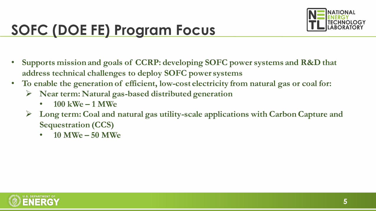
SOFC (DOE FE) Program Focus
• Supports mission and goals of CCRP: developing SOFC power systems and R&D that
address technical challenges to deploy SOFC power systems
• To enable the generation of efficient, low-cost electricity from natural gas or coal for:
➢ Near term: Natural gas-based distributed generation
• 100 kWe – 1 MWe➢ Long term: Coal and natural gas utility-scale applications with Carbon Capture and
Sequestration (CCS)
• 10 MWe – 50 MWe

6
KEY TECHNOLOGIESTECHNOLOGY AREA
SOFC (DOE FE) Program Structure Key Technologies
SOLID OXIDE FUEL CELLS
Core Technology
Systems
Development
Cell Development
Figure courtesy FuelCell Energy
Figure courtesy LG Fuel Cell Systems
Figure courtesy NETL

7
SOFC Program Project PortfolioFY19 Participants
8
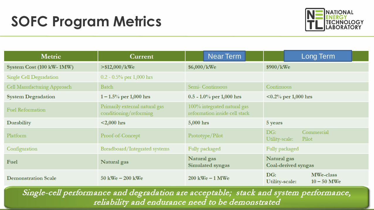
SOFC Program Metrics
*NOC: Normal Operating Conditions
Near Term Long Term

9
SOFC Program: Technology-specific Challenges
Technology Topic Challenges
CellsManufacturing/QC
• Manufacturing reliability/quality control issues.
• Non-destructive tests
• Cell–to-cell variability
Chemical Instability • Microstructural/chemical changes in cell due to high temperature
Stacks
Manufacturing/QC • Dimensional tolerances
Contacts • Electrode-Interconnect contact variability and degradation
Seals• Seal failure
• Corrosion of brazes/welds
• Thermal gradients/management
Systems
Electrode Contamination • Cathode poisoning (e.g. Cr)
Anode Redox • Anode redox expansion/contraction
Commissioning• Integration and reliability of first-of-a-kind system
• Purpose-specific BOP components
• Unplanned shutdowns

10
SOFC Program: Partners and their roles

11
➢The Program continues to support cell and stack R&D … however …
➢Program emphasis is shifting to the resolution of design, operation, and performance considerations at the system level
➢ Identified critical reliability issues and put into place R&D projects to resolve these issues
➢Demonstrated Proof-of-Concept systems at ratings up to 200 kWe
➢Acquiring fabricating and operational experience on integrated, prototype field tests
➢ Initiated RD&D into the next generation of cell and stack architectures
SOFC ProgramKey Takeaways

12
• Most improvements have been on the cathode side• Cathode infiltration
• Cathode capping layers – blocks strontium segregations and precipitation
• Additional development of mixed ionic electronic conductors
• Optimizations in processing (firing temp, particle size distributions, etc…)
• Why focus on the cathode?• Appreciation for YSZ’s amazing properties
• Anodes are fairly stable and have worked “well-enough”
• At the time, cathodes were the performance bottle neck
• Most degradation occurred on the cathode side
Improving the Cell Performance

13
•There are still opportunities for improving the cathode• Additional development on MIECs
• Nickelate cathodes
• Potential for higher performance and innate resistance to chrome poisoning
• Engineered cathodes with tri-layer structures• Further separates electrochemical functions for additional optimization
• Potential for more optimized cathode structures
• Thin layers offer possibilities for new materials• Insulators aren’t bad conductors if they are thin enough
New Cathode Materials

14
• Work at NETL to improve the anode through infiltration• More difficult than infiltrating the cathode due to density and thickness, but possible.
• Improve electrochemical performance, coking resistance, and possibly redox tolerance
• Work at Montana State University to add anchoring phases to anode• Increase strength by up to 50% (allows for 33% thinner anode)
• Thinner anodes allow for higher fuel utilizations
• Reduces steam concentration in the active area
• Significant reduction in material cost
• Increases in redox tolerance
• Work at UES and University of Connecticut
• HEA as an internal reforming anode materials
Anode Materials
15
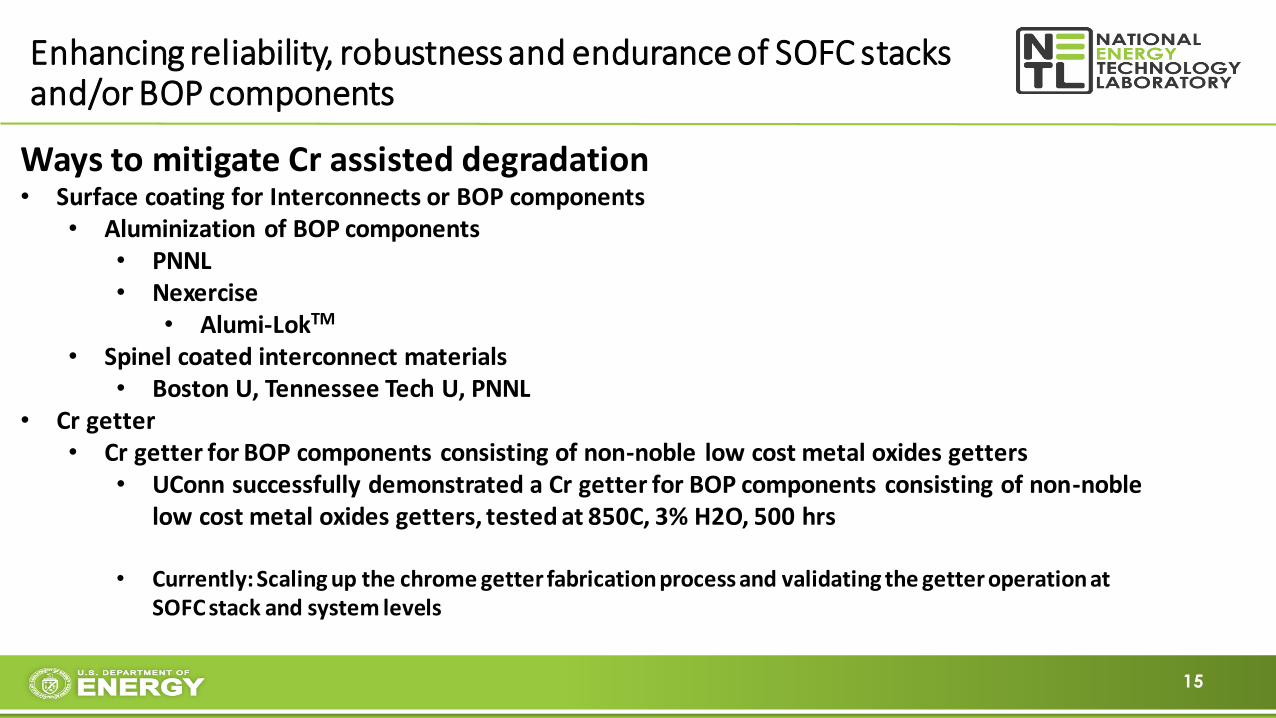
Enhancing reliability, robustness and endurance of SOFC stacks and/or BOP components
Ways to mitigate Cr assisted degradation• Surface coating for Interconnects or BOP components
• Aluminization of BOP components• PNNL• Nexercise
• Alumi-LokTM
• Spinel coated interconnect materials• Boston U, Tennessee Tech U, PNNL
• Cr getter• Cr getter for BOP components consisting of non-noble low cost metal oxides getters
• UConn successfully demonstrated a Cr getter for BOP components consisting of non-noble low cost metal oxides getters, tested at 850C, 3% H2O, 500 hrs
• Currently: Scaling up the chrome getter fabrication process and validating the getter operation at SOFC stack and system levels

16
• Modified cathode materials
• Cr tolerant cathodes
• Georgia Tech (Infiltrated cathodes, catalyst-coated cathodes)
• University of South Carolina
• Cathodes and contact paste consisting of chromium getter to minimize cathode degradation
• Uconn
• Tennessee Technological University
• Understand mechanisms of Cr effects on cathodes and propose ways to mitigate
• Boston U, UConn
• Acceleration tests on cathodes in the presence of chromium contamination
• Various approaches to minimizing the presence of Cr in the system environment
Ways to mitigate Cr assisted degradation

17
• Alloy chemistry of BOP components
• Fe and Ni based chromia and alumina forming alloys
• Block and reduce Cr evaporation rates from BOP components
• West Virginia University
• Cr sensor
• Monitoring the chromium vapor produced during SOFC operation
• GE, Auburn Universities
Ways to mitigate Cr assisted degradation

18
ALD unique characteristics
• Thickness control• Uniformity and conformality• Tailor compositions in precise manner• Low temperature• Almost anything from the periodic table can be deposited by ALD
• pure components, mixed oxides• Best suited for depositing multicomponent materials because of its stepwise approach.• Adding catalytic materials to the electrode surface without changing the electrode morphology
• performance can be more clearly linked to surface coverage.• Typical ALD materials
• Oxides, nitrides, carbides• Pure element (metal)

19
• Currently there are 10 projects under SOFC portfolio
• West Virginia University, University of Pennsylvania, University of South Carolina, Georgia Tech, Michigan State University, Sonata
• Most of them focus on using ALD to enhance cathode performance
• Catalysts: single materials, multi-components
• Multifunctional
• Resistance to impurities/contaminations
• Prevent grain coarsening
• Long term stability of cathode
• Surface modification layer on cathode powders (drop-in process).
• One project using ALD to enhance anode capability • Direct hydrocarbon (methane) SOFC applications
• One project using ALD for barrier layer of the interconnect
ALD related SOFC Projects

20
• Testing
• Most test done in half-cells/symmetrical cells/button cells.
• Need to be tested in full size cells and short stack to bridge the gap between the academic research and industrial scale up.
• Need more longer-term test
• Technology transfer
• FCE and Atrex
• Test at Industry team facility
• Stack level
• Real SOFC environments.
• Perform ALD coating on the Industry team’s cells
ALD related SOFC Projects

21
Challenges in ALD
• The properties of ALD-modified materials depend highly on the procedures and conditions used to carry out the ALD growth
• ALD equipment/reactor (in house or commercial)• Inconsistencies of growth rates• Dense or porous ALD layers• One project to understand ALD mechanisms and what causes a challenge
• Scale-up• Cost Analysis

22
SOFC R&D at NETL
Systems Engineering and Analysis
Cell and Stack Degradation Modeling
Electrode Engineering
• Development of
comprehensive predictive
modeling tool
• Atoms to system scale bridging
• Validated through experiment
• Mitigation of prominent
degradation modes
• Successful transfer of
technology to industry
• Public dissemination of
SOFC market potential,
performance, and cost
advantages
• Hybrid configuration
assessment
• Tie to R&D goals and
objectives
High Temp Optical Sensors
• Multi-application technology
under development for high
temperature sensing
• Demonstrated in SOFC
• In-situ sensing of
temperature distribution and
gas composition
23
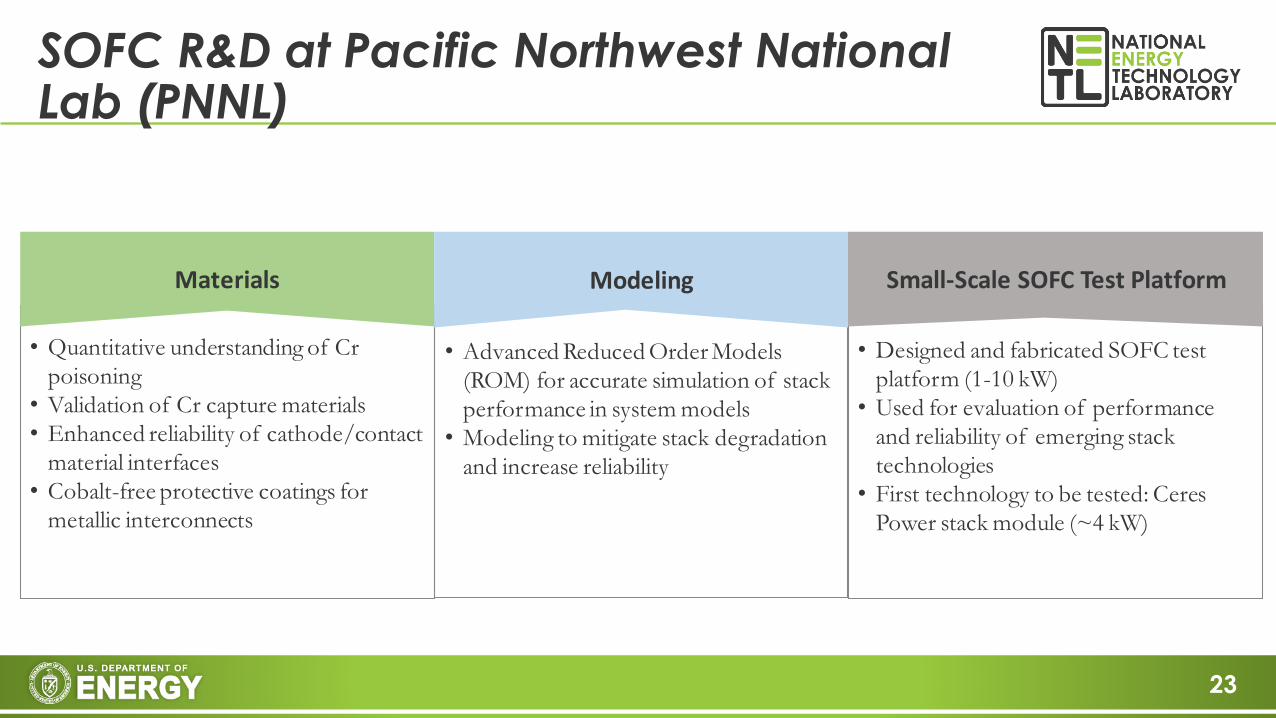
SOFC R&D at Pacific Northwest National Lab (PNNL)
Small-Scale SOFC Test PlatformMaterials Modeling
• Quantitative understanding of Cr
poisoning
• Validation of Cr capture materials
• Enhanced reliability of cathode/contact
material interfaces
• Cobalt-free protective coatings for
metallic interconnects
• Advanced Reduced Order Models
(ROM) for accurate simulation of stack
performance in system models
• Modeling to mitigate stack degradation
and increase reliability
• Designed and fabricated SOFC test
platform (1-10 kW)
• Used for evaluation of performance
and reliability of emerging stack
technologies
• First technology to be tested: Ceres
Power stack module (~4 kW)
24
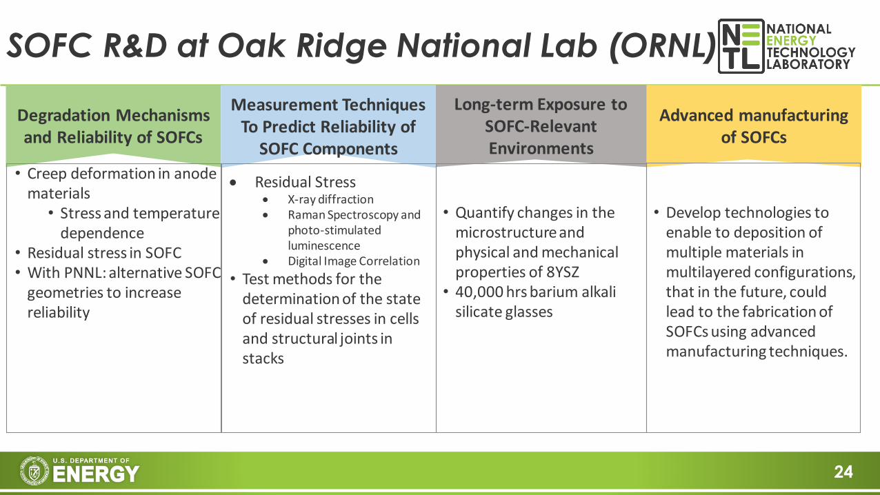
SOFC R&D at Oak Ridge National Lab (ORNL)
• Creep deformation in anode materials
• Stress and temperature dependence
• Residual stress in SOFC• With PNNL: alternative SOFC
geometries to increase reliability
Long-term Exposure to SOFC-Relevant Environments
Degradation Mechanisms and Reliability of SOFCs
Measurement TechniquesTo Predict Reliability of
SOFC Components
Advanced manufacturing of SOFCs
• Residual Stress• X-ray diffraction• Raman Spectroscopy and
photo-stimulated luminescence
• Digital Image Correlation
• Test methods for the determination of the state of residual stresses in cells and structural joints in stacks
• Quantify changes in the microstructure and physical and mechanical properties of 8YSZ
• 40,000 hrs barium alkali silicate glasses
• Develop technologies to enable to deposition of multiple materials in multilayered configurations, that in the future, could lead to the fabrication of SOFCs using advanced manufacturing techniques.
25
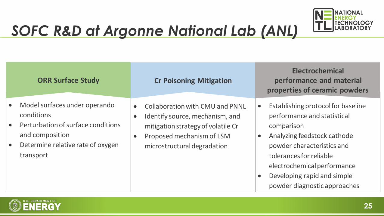
SOFC R&D at Argonne National Lab (ANL)
Electrochemicalperformance and material
properties of ceramic powdersORR Surface Study Cr Poisoning Mitigation
• Model surfaces under operando
conditions
• Perturbation of surface conditions
and composition
• Determine relative rate of oxygen
transport
• Collaboration with CMU and PNNL
• Identify source, mechanism, and
mitigation strategy of volatile Cr
• Proposed mechanism of LSM
microstructural degradation
• Establishing protocol for baseline
performance and statistical
comparison
• Analyzing feedstock cathode
powder characteristics and
tolerances for reliable
electrochemical performance
• Developing rapid and simple
powder diagnostic approaches

26
• March 2019 to end of October 2019
• High electrical efficiency (greater than 50%)
• Low environmental impact (ultra-low SOx, NOx, and PM emissions due to no combustion)
• No water consumption during power generation mode
• Available heat for Combined Heat and Power (CHP) applications
• Fully automatic with turnkey operation (unattended operation)
• Quiet operation
• Truck transportable
and easily installed
SOFC Program: Systems Development
Fuel Cell Energy 200 kW SOFC prototype

27

28
21st Annual Solid Fuel Cell (SOFC) Project Review Meeting
To be held on July 21-23, 2020
Pittsburgh Airport Marriott Hotel, Pittsburgh, Pennsylvania.

29
For Additional Information
Office of Fossil Energy: www.energy.gov/fe/office-fossil-energyNETL Website: www.netl.doe.gov/SOFC Program website: www.netl.doe.gov/coal/research/energy-systems/fuel-cellsReference Shelf:
- SOFC Program FY19 Project Portfolio- SOFC Technology Program Plan- Technology Readiness Assessment- Past Workshop Proceedings- Systems Analysis- Fuel Cell Handbook
Dr. Shailesh D. VoraTechnology Manager, Fuel Cells National Energy Technology LaboratoryU. S. Department of [email protected]