usbx™ device class cdc-acm module guide - application project
TRANSCRIPT
Application Note
R11AN0171EU0101 Rev.1.01 Page 1 of 17 Feb.07.19
Renesas Synergy™ Platform
USBX™ Device Class CDC-ACM Module Guide Introduction This module guide will enable you to effectively use a module in your own design. Upon completion of this guide, you will be able to add this module to your own design, configure it correctly for the target application and write code, using the included application project code as a reference and efficient starting point. References to more detailed API descriptions and suggestions of other application projects that illustrate more advanced uses of the module are available in the Renesas Synergy™ Knowledge Base (as described in the Reference section at the end of this document), and are valuable resources for creating more complex designs. The USBX™ Device Class CDC-ACM module is a high-level API for USBX Device Class CDC-ACM module applications and is implemented on the USBX Port CDC for USB Full Speed (USBFS) or USB High Speed (USBHS). The USBX Device CDC-ACM module uses the USB and data-transfer peripherals on the Synergy MCU. A user defined callback can be created to determine when the stack activates or deactivates the USB CDC-ACM class. This document provides an overview of the key elements related to the USBX Device Class CDC-ACM module implementation on the Renesas Synergy™ Platform. This document’s primary focus is on the addition and configuration of the USBX Device Class CDC-ACM module to a Renesas Synergy Platform project. For more details on the operation of this module, consult the USBX User’s Guide for the Renesas Synergy Platform document. This document is available as part of an X-Ware™ and USBX Component Documents for Renesas Synergy™ zip file from the Renesas Synergy SSP page (www.renesas.com/synergy/ssp).
Renesas Synergy™ Platform USBX™ Device Class CDC-ACM Module Guide
R11AN0171EU0101 Rev.1.01 Page 2 of 17 Feb.07.19
Contents
1. USBX Device Class CDC-ACM Module Features...................................................................3
2. USBX Device Class CDC-ACM Module Overview ..................................................................3
3. USBX Device Class CDC-ACM Module Operational Overview ...............................................4 3.1 USBX Device Class CDC-ACM Module Important Operational Notes and Limitations ....................... 4 3.2 USBX Device Class CDC-ACM Module Operational Notes........................................................... 4
4. Including the USBX Device Class CDC-ACM Module in an Application ..................................4
5. Configuring the USBX Device Class CDC-ACM Module .........................................................5 5.1 Configuration Settings for the USBX Device Class CDC-ACM Module Low-Level Modules................ 6 5.2 USBX Device Class CDC-ACM Module Clock Configuration......................................................... 9 5.3 USBX Device Class CDC-ACM Module Pin Configuration ............................................................ 9
6. Using the USBX Device Class CDC-ACM Module in an Application .....................................10
7. The USBX Device Class CDC-ACM Module Application Project ...........................................11
8. Customizing the USBX Device Class CDC-ACM Module for a Target Application .................12
9. Running the USBX Device Class CDC-ACM Module Application Project ..............................13 9.1 An Important Note on USB Drive Set-up .................................................................................. 13 9.2 Implementing the Application Project in a New Project ............................................................... 13
10. USBX Device Class CDC-ACM Module Conclusion .............................................................14
11. USBX Device Class CDC-ACM Module Next Steps .............................................................14
12. USBX Device Class CDC-ACM Module Reference Information ............................................15
Revision History .........................................................................................................................17
Renesas Synergy™ Platform USBX™ Device Class CDC-ACM Module Guide
R11AN0171EU0101 Rev.1.01 Page 3 of 17 Feb.07.19
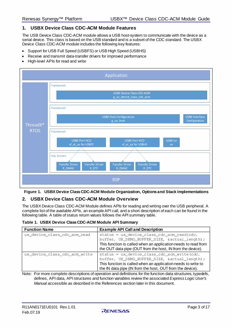
1. USBX Device Class CDC-ACM Module Features The USB Device Class CDC-ACM module allows a USB host-system to communicate with the device as a serial device. This class is based on the USB standard and is a subset of the CDC standard. The USBX Device Class CDC-ACM module includes the following key features: • Support for USB Full Speed (USBFS) or USB High Speed (USBHS) • Receive and transmit data-transfer drivers for improved performance • High-level APIs for read and write
Figure 1. USBX Device Class CDC-ACM Module Organization, Options and Stack Implementations
2. USBX Device Class CDC-ACM Module Overview The USBX Device Class CDC-ACM Module defines APIs for reading and writing over the USB peripheral. A complete list of the available APIs, an example API call, and a short description of each can be found in the following table. A table of status return values follows the API summary table.
Table 1. USBX Device Class CDC-ACM Module API Summary Function Name Example API Call and Description ux_device_class_cdc_acm_read status = ux_device_class_cdc_acm_read(cdc,
buffer, UX_DEMO_BUFFER_SIZE, &actual_length); This function is called when an application needs to read from the OUT data pipe (OUT from the host, IN from the device).
ux_device_class_cdc_acm_write status = ux_device_class_cdc_acm_write(cdc, buffer, UX_DEMO_BUFFER_SIZE, &actual_length); This function is called when an application needs to write to the IN data pipe (IN from the host, OUT from the device).
Note: For more complete descriptions of operation and definitions for the function data structures, typedefs, defines, API data, API structures and function variables review the associated Express Logic User’s Manual accessible as described in the References section later in this document.
Renesas Synergy™ Platform USBX™ Device Class CDC-ACM Module Guide
R11AN0171EU0101 Rev.1.01 Page 4 of 17 Feb.07.19
Table 2. Status Return Values Name Description UX_SUCCESS This operation was successful. UX_CONFIGURATION_HANDLE_UNKNOWN Device is no longer in the configured state. UX_TRANSFER_NO_ANSWER No answer from device. The device was probably
disconnected while the transfer was pending. Note: Lower-level drivers may return common error codes. Refer to the SSP User’s Manual API References
for the associated module for a definition of all relevant status return values.
3. USBX Device Class CDC-ACM Module Operational Overview The initialization of the CDC-ACM class expects some specific parameters as illustrated in the application project associated with this module guide. The CDC-ACM is based on a USB-IF standard and is automatically recognized by Mac OS® and Linux OS®. On Windows® platforms, this class requires a .inf file. Express Logic® supplies a template for the CDC-ACM class, and it can be found in the usbx_windows_host_files directory. For more recent versions of Windows, the file CDC_ACM_Template_Win7_64bit.inf should be used. This file needs to be modified to reflect the PID/VID used by the device. The PID/VID will be specific to the final customer when the company and the product are registered with the USB-IF. In the .inf file, the fields to modify are described in the application project associated with this module guide. In the device framework of the USBX CDC-ACM device, the PID/VID are stored in the device descriptor (see the device descriptor declared in the application project referenced in the preceding paragraph). When a USB host-system discovers the USBX CDC-ACM device, it will mount a serial class and the device can be used with any serial terminal program. (See the host operating system for reference.)
3.1 USBX Device Class CDC-ACM Module Important Operational Notes and Limitations
The application needs to save the instance with the callback function registered in USBX CDC-ACM instance_activate function callback. Read and write are executed using the saved instance.
3.2 USBX Device Class CDC-ACM Module Operational Notes Refer to the most recent SSP Release Notes for any additional operational limitations for this module.
4. Including the USBX Device Class CDC-ACM Module in an Application This section describes how to include the USBX Device Class CDC-ACM module in an application using the SSP configurator. Note: This section assumes you are familiar with creating a project, adding threads, adding a stack to a
thread and configuring a block within the stack. If you are unfamiliar with any of these items, refer to the first few chapters of the SSP User’s Manual to learn how to manage each of these important steps in creating SSP-based applications.
To add the USBX Device Class CDC-ACM module to an application, simply add it to a thread using the stacks selection sequence given in the following table. (The default name for the USBX Device CDC-ACM module is g_ux_device_class_cdc_acm0. This name can be changed in the associated Properties window.)
Table 3. USBX Device Class HID Selection Sequence Resource ISDE Tab Stacks Selection Sequence g_ux_device_class_cdc_acm0 USBX Device Class CDC-ACM
Threads New Stack> X-Ware> USBX> Device> Classes > CDC-ACM > USBX Device Class CDC-ACM
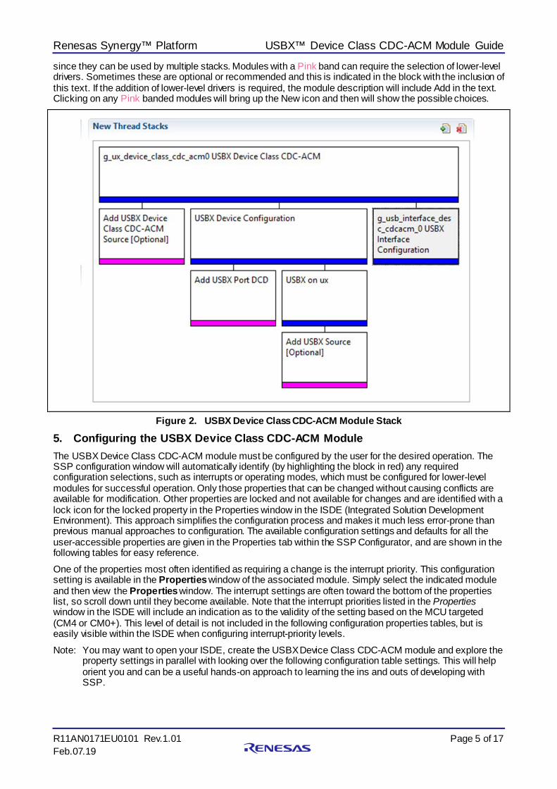
When the USBX Device Class CDC-ACM module added to the thread stack as shown in the following figure, the configurator automatically adds the needed lower-level drivers. Any drivers that need additional configuration information will be box text highlighted in Red. Modules with a Gray band are individual modules that stand alone. Modules with a Blue band are shared or common and need only be added once,
Renesas Synergy™ Platform USBX™ Device Class CDC-ACM Module Guide
R11AN0171EU0101 Rev.1.01 Page 5 of 17 Feb.07.19
since they can be used by multiple stacks. Modules with a Pink band can require the selection of lower-level drivers. Sometimes these are optional or recommended and this is indicated in the block with the inclusion of this text. If the addition of lower-level drivers is required, the module description will include Add in the text. Clicking on any Pink banded modules will bring up the New icon and then will show the possible choices.
Figure 2. USBX Device Class CDC-ACM Module Stack
5. Configuring the USBX Device Class CDC-ACM Module The USBX Device Class CDC-ACM module must be configured by the user for the desired operation. The SSP configuration window will automatically identify (by highlighting the block in red) any required configuration selections, such as interrupts or operating modes, which must be configured for lower-level modules for successful operation. Only those properties that can be changed without causing conflicts are available for modification. Other properties are locked and not available for changes and are identified with a lock icon for the locked property in the Properties window in the ISDE (Integrated Solution Development Environment). This approach simplifies the configuration process and makes it much less error-prone than previous manual approaches to configuration. The available configuration settings and defaults for all the user-accessible properties are given in the Properties tab within the SSP Configurator, and are shown in the following tables for easy reference. One of the properties most often identified as requiring a change is the interrupt priority. This configuration setting is available in the Properties window of the associated module. Simply select the indicated module and then view the Properties window. The interrupt settings are often toward the bottom of the properties list, so scroll down until they become available. Note that the interrupt priorities listed in the Properties window in the ISDE will include an indication as to the validity of the setting based on the MCU targeted (CM4 or CM0+). This level of detail is not included in the following configuration properties tables, but is easily visible within the ISDE when configuring interrupt-priority levels. Note: You may want to open your ISDE, create the USBX Device Class CDC-ACM module and explore the
property settings in parallel with looking over the following configuration table settings. This will help orient you and can be a useful hands-on approach to learning the ins and outs of developing with SSP.
Renesas Synergy™ Platform USBX™ Device Class CDC-ACM Module Guide
R11AN0171EU0101 Rev.1.01 Page 6 of 17 Feb.07.19
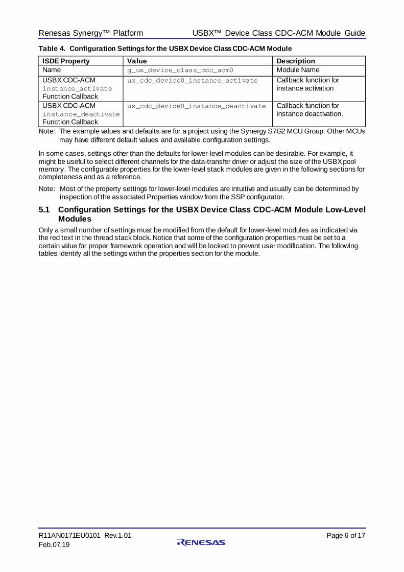
Table 4. Configuration Settings for the USBX Device Class CDC-ACM Module ISDE Property Value Description Name g_ux_device_class_cdc_acm0 Module Name USBX CDC-ACM instance_activate Function Callback
ux_cdc_device0_instance_activate Callback function for instance activation
USBX CDC-ACM instance_deactivate Function Callback
ux_cdc_device0_instance_deactivate Callback function for instance deactivation.
Note: The example values and defaults are for a project using the Synergy S7G2 MCU Group. Other MCUs may have different default values and available configuration settings.
In some cases, settings other than the defaults for lower-level modules can be desirable. For example, it might be useful to select different channels for the data-transfer driver or adjust the size of the USBX pool memory. The configurable properties for the lower-level stack modules are given in the following sections for completeness and as a reference. Note: Most of the property settings for lower-level modules are intuitive and usually can be determined by
inspection of the associated Properties window from the SSP configurator.
5.1 Configuration Settings for the USBX Device Class CDC-ACM Module Low-Level Modules
Only a small number of settings must be modified from the default for lower-level modules as indicated via the red text in the thread stack block. Notice that some of the configuration properties must be set to a certain value for proper framework operation and will be locked to prevent user modification. The following tables identify all the settings within the properties section for the module.
Renesas Synergy™ Platform USBX™ Device Class CDC-ACM Module Guide
R11AN0171EU0101 Rev.1.01 Page 7 of 17 Feb.07.19
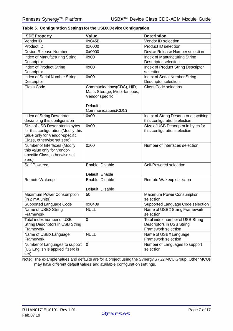
Table 5. Configuration Settings for the USBX Device Configuration
Note: The example values and defaults are for a project using the Synergy S7G2 MCU Group. Other MCUs may have different default values and available configuration settings.
ISDE Property Value Description Vendor ID 0x045B Vendor ID selection Product ID 0x0000 Product ID selection Device Release Number 0x0000 Device Release Number selection Index of Manufacturing String Descriptor
0x00 Index of Manufacturing String Descriptor selection
Index of Product String Descriptor
0x00 Index of Product String Descriptor selection
Index of Serial Number String Descriptor
0x00 Index of Serial Number String Descriptor selection
Class Code Communications(CDC), HID, Mass Storage, Miscellaneous, Vendor specific Default: Communications(CDC)
Class Code selection
Index of String Descriptor describing this configuration
0x00 Index of String Descriptor describing this configuration selection
Size of USB Descriptor in bytes for this configuration (Modify this value only for Vendor-specific Class, otherwise set zero)
0x00 Size of USB Descriptor in bytes for this configuration selection
Number of Interfaces (Modify this value only for Vendor-specific Class, otherwise set zero)
0x00 Number of Interfaces selection
Self-Powered Enable, Disable Default: Enable
Self-Powered selection
Remote Wakeup Enable, Disable Default: Disable
Remote Wakeup selection
Maximum Power Consumption (in 2 mA units)
50 Maximum Power Consumption selection
Supported Language Code 0x0409 Supported Language Code selection Name of USBX String Framework
NULL Name of USBX String Framework selection
Total index number of USB String Descriptors in USB String Framework
0 Total index number of USB String Descriptors in USB String Framework selection
Name of USBX Language Framework
NULL Name of USBX Language Framework selection
Number of Languages to support (US English is applied if zero is set)
0 Number of Languages to support selection
Renesas Synergy™ Platform USBX™ Device Class CDC-ACM Module Guide
R11AN0171EU0101 Rev.1.01 Page 8 of 17 Feb.07.19
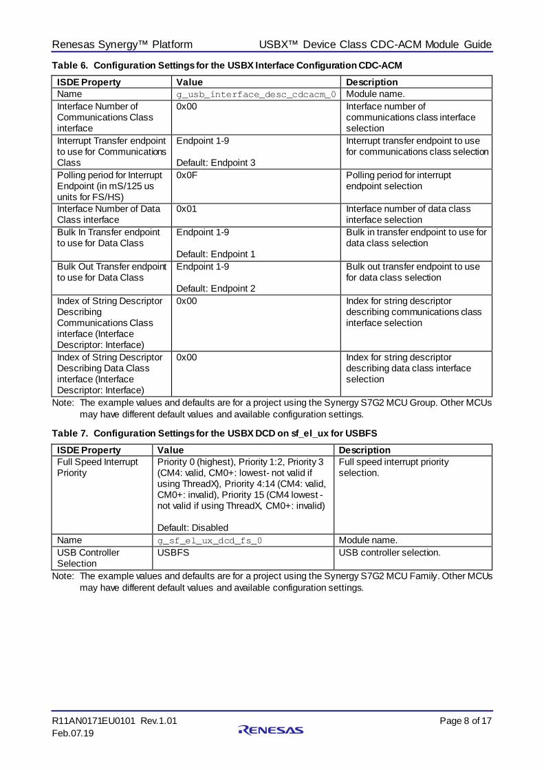
Table 6. Configuration Settings for the USBX Interface Configuration CDC-ACM ISDE Property Value Description Name g_usb_interface_desc_cdcacm_0 Module name. Interface Number of Communications Class interface
0x00 Interface number of communications class interface selection
Interrupt Transfer endpoint to use for Communications Class
Endpoint 1-9 Default: Endpoint 3
Interrupt transfer endpoint to use for communications class selection
Polling period for Interrupt Endpoint (in mS/125 us units for FS/HS)
0x0F Polling period for interrupt endpoint selection
Interface Number of Data Class interface
0x01 Interface number of data class interface selection
Bulk In Transfer endpoint to use for Data Class
Endpoint 1-9 Default: Endpoint 1
Bulk in transfer endpoint to use for data class selection
Bulk Out Transfer endpoint to use for Data Class
Endpoint 1-9 Default: Endpoint 2
Bulk out transfer endpoint to use for data class selection
Index of String Descriptor Describing Communications Class interface (Interface Descriptor: Interface)
0x00 Index for string descriptor describing communications class interface selection
Index of String Descriptor Describing Data Class interface (Interface Descriptor: Interface)
0x00 Index for string descriptor describing data class interface selection
Note: The example values and defaults are for a project using the Synergy S7G2 MCU Group. Other MCUs may have different default values and available configuration settings.
Table 7. Configuration Settings for the USBX DCD on sf_el_ux for USBFS ISDE Property Value Description Full Speed Interrupt Priority
Priority 0 (highest), Priority 1:2, Priority 3 (CM4: valid, CM0+: lowest- not valid if using ThreadX), Priority 4:14 (CM4: valid, CM0+: invalid), Priority 15 (CM4 lowest - not valid if using ThreadX, CM0+: invalid) Default: Disabled
Full speed interrupt priority selection.
Name g_sf_el_ux_dcd_fs_0 Module name. USB Controller Selection
USBFS USB controller selection.
Note: The example values and defaults are for a project using the Synergy S7G2 MCU Family. Other MCUs may have different default values and available configuration settings.
Renesas Synergy™ Platform USBX™ Device Class CDC-ACM Module Guide
R11AN0171EU0101 Rev.1.01 Page 9 of 17 Feb.07.19
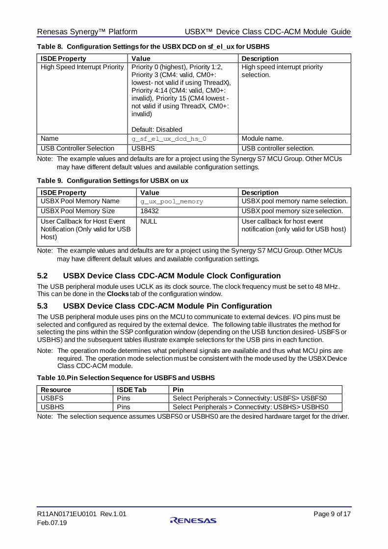
Table 8. Configuration Settings for the USBX DCD on sf_el_ux for USBHS ISDE Property Value Description High Speed Interrupt Priority Priority 0 (highest), Priority 1:2,
Priority 3 (CM4: valid, CM0+: lowest- not valid if using ThreadX), Priority 4:14 (CM4: valid, CM0+: invalid), Priority 15 (CM4 lowest - not valid if using ThreadX, CM0+: invalid) Default: Disabled
High speed interrupt priority selection.
Name g_sf_el_ux_dcd_hs_0 Module name. USB Controller Selection USBHS USB controller selection.
Note: The example values and defaults are for a project using the Synergy S7 MCU Group. Other MCUs may have different default values and available configuration settings.
Table 9. Configuration Settings for USBX on ux ISDE Property Value Description USBX Pool Memory Name g_ux_pool_memory USBX pool memory name selection. USBX Pool Memory Size 18432 USBX pool memory size selection. User Callback for Host Event Notification (Only valid for USB Host)
NULL User callback for host event notification (only valid for USB host)
Note: The example values and defaults are for a project using the Synergy S7 MCU Group. Other MCUs may have different default values and available configuration settings.
5.2 USBX Device Class CDC-ACM Module Clock Configuration The USB peripheral module uses UCLK as its clock source. The clock frequency must be set to 48 MHz. This can be done in the Clocks tab of the configuration window.
5.3 USBX Device Class CDC-ACM Module Pin Configuration The USB peripheral module uses pins on the MCU to communicate to external devices. I/O pins must be selected and configured as required by the external device. The following table illustrates the method for selecting the pins within the SSP configuration window (depending on the USB function desired- USBFS or USBHS) and the subsequent tables illustrate example selections for the USB pins in each function. Note: The operation mode determines what peripheral signals are available and thus what MCU pins are
required. The operation mode selection must be consistent with the mode used by the USBX Device Class CDC-ACM module.
Table 10. Pin Selection Sequence for USBFS and USBHS Resource ISDE Tab Pin USBFS Pins Select Peripherals > Connectivity: USBFS> USBFS0 USBHS Pins Select Peripherals > Connectivity: USBHS> USBHS0
Note: The selection sequence assumes USBFS0 or USBHS0 are the desired hardware target for the driver.
Renesas Synergy™ Platform USBX™ Device Class CDC-ACM Module Guide
R11AN0171EU0101 Rev.1.01 Page 10 of 17 Feb.07.19
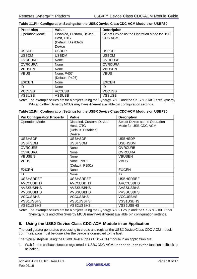
Table 11. Pin Configuration Settings for the USBX Device Class CDC-ACM Module on USBFS0 Properties Value Description Operation Mode Disabled, Custom, Device,
Host, OTG (Default: Disabled) Device
Select Device as the Operation Mode for USB CDC-ACM
USBDP USBDP USPDP USBDM USBDM USBDM OVRCURB None OVRCURB OVRCURA None OVRCURA VBUSEN None VBUSEN VBUS None, P407
(Default: P407) VBUS
EXICEN None EXICEN ID None ID VCCUSB VCCUSB VCCUSB VSSUSB VSSUSB VSSUSB
Note: The example values are for a project using the Synergy S7G2 and the SK-S7G2 Kit. Other Synergy Kits and other Synergy MCUs may have different available pin configuration settings.
Table 12. Pin Configuration Settings for the USBX Device Class CDC-ACM Module on USBFS0 Pin Configuration Property Value Description Operation Mode Disabled, Custom, Device,
Host, OTG (Default: Disabled) Device
Select Device as the Operation Mode for USB CDC-ACM
USBHSDP USBHSDP USBHSDP USBHSDM USBHSDM USBHSDM OVRCURB None OVRCURB OVRCURA None OVRCURA VBUSEN None VBUSEN VBUS None, PB01
(Default: PB01) VBUS
EXICEN None EXICEN ID None ID USBHSRREF USBHSRREF USBHSRREF AVCCUSBHS AVCCUSBHS AVCCUSBHS AVSSUSBHS AVSSUSBHS AVSSUSBHS PVSSUSBHS PVSSUSBHS PVSSUSBHS VCCUSBHS VCCUSBHS VCCUSBHS VSS1USBHS VSS1USBHS VSS1USBHS VSS2USBHS VSS2USBHS VSS2USBHS
Note: The example values are for a project using the Synergy S7G2 Group and the SK-S7G2 Kit. Other Synergy Kits and other Synergy MCUs may have different available pin configuration settings.
6. Using the USBX Device Class CDC-ACM Module in an Application The configurator generates processing to create and register the USBX Device Class CDC-ACM module; communication must be done after the device is connected to the host. The typical steps in using the USBX Device Class CDC-ACM module in an application are: 1. Wait for the callback function registered in USBX CDC-ACM instance_activate function callback to
be called.
Renesas Synergy™ Platform USBX™ Device Class CDC-ACM Module Guide
R11AN0171EU0101 Rev.1.01 Page 11 of 17 Feb.07.19
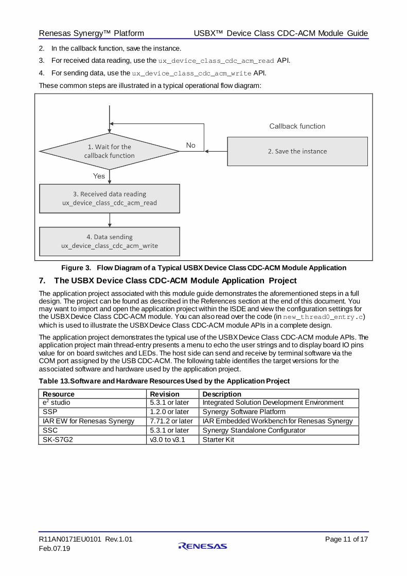
2. In the callback function, save the instance. 3. For received data reading, use the ux_device_class_cdc_acm_read API.
4. For sending data, use the ux_device_class_cdc_acm_write API.
These common steps are illustrated in a typical operational flow diagram:
Figure 3. Flow Diagram of a Typical USBX Device Class CDC-ACM Module Application
7. The USBX Device Class CDC-ACM Module Application Project The application project associated with this module guide demonstrates the aforementioned steps in a full design. The project can be found as described in the References section at the end of this document. You may want to import and open the application project within the ISDE and view the configuration settings for the USBX Device Class CDC-ACM module. You can also read over the code (in new_thread0_entry.c) which is used to illustrate the USBX Device Class CDC-ACM module APIs in a complete design. The application project demonstrates the typical use of the USBX Device Class CDC-ACM module APIs. The application project main thread-entry presents a menu to echo the user strings and to display board IO pins value for on board switches and LEDs. The host side can send and receive by terminal software via the COM port assigned by the USB CDC-ACM. The following table identifies the target versions for the associated software and hardware used by the application project. Table 13. Software and Hardware Resources Used by the Application Project
Resource Revision Description e2 studio 5.3.1 or later Integrated Solution Development Environment SSP 1.2.0 or later Synergy Software Platform IAR EW for Renesas Synergy 7.71.2 or later IAR Embedded Workbench for Renesas Synergy SSC 5.3.1 or later Synergy Standalone Configurator SK-S7G2 v3.0 to v3.1 Starter Kit
Renesas Synergy™ Platform USBX™ Device Class CDC-ACM Module Guide
R11AN0171EU0101 Rev.1.01 Page 12 of 17 Feb.07.19
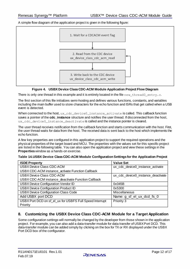
A simple flow diagram of the application project is given in the following figure:
Figure 4. USBX Device Class CDC-ACM Module Application Project Flow Diagram There is only one thread in this example and it is entirely located in the file new_thread0_entry.c.
The first section of this file initializes semi-hosting and defines various functions, constants, and variables including the main buffer used to store characters for the echo function and ISRs that get called when a USB event is detected. When connected to the host, ux_cdc_device0_instance_activate is called. This callback function saves a pointer of the cdc_instance structure and notifies the user thread. If disconnected from the host, ux_cdc_device0_instance_deactivate is called and the instance pointer is cleared.
The user thread receives notification from the callback function and starts communication with the host. First, the user thread waits for data from the host. The received data is sent back to the host which implements the echo function. A few key properties are configured in this application project to support the required operations and the physical properties of the target board and MCU. The properties with the values set for this specific project are listed in the following table. You can also open the application project and view these settings in the Properties window as a hands-on exercise. Table 14. USBX Device Class CDC-ACM Module Configuration Settings for the Application Project
ISDE Property Value Set USBX Device Class CDC-ACM USBX CDC-ACM instance_activate Function Callback
ux_cdc_device0_instance_activate
USBX Device Class CDC-ACM USBX CDC-ACM instance_deactivate Function Callback
ux_cdc_device0_instance_deactivate
USBX Device Configuration Vendor ID 0x045B USBX Device Configuration Product ID 0x5300 USBX Device Configuration Class Code Miscellaneous Add USBX port DCD Name: g_sf_el_ux_dcd_fs_0 USBX Port DCD on sf_el_ux for USBFS Full Speed Interrupt Priority
Priority 3
8. Customizing the USBX Device Class CDC-ACM Module for a Target Application Some configuration settings will normally be changed by the developer from those shown in the application project. For example, you can also add a data-transfer module for data transfer of USBX Port DCD. This data-transfer module can be added simply by clicking on the box for TX or RX displayed under the USBX Port DCD box of the configurator.
Renesas Synergy™ Platform USBX™ Device Class CDC-ACM Module Guide
R11AN0171EU0101 Rev.1.01 Page 13 of 17 Feb.07.19
9. Running the USBX Device Class CDC-ACM Module Application Project To run the USBX Device Class CDC-ACM module application project and to see it executed on a target kit, you can simply import it into your ISDE, compile and run debug. Refer to the Synergy Project Import Guide (r11an0023eu0121-synergy-ssp-import-guide.pdf, included in this package) for instructions on importing the project into e2 studio ISDE or IAR EW for Synergy and building/running the application.
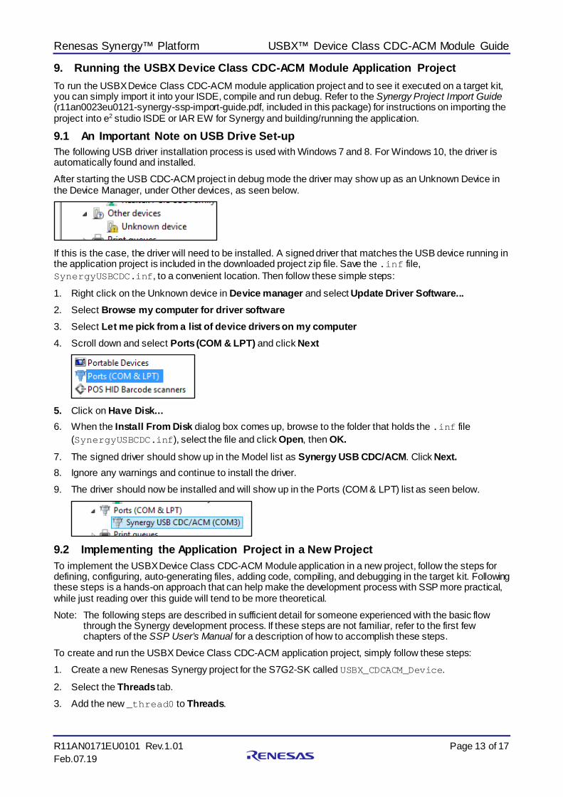
9.1 An Important Note on USB Drive Set-up The following USB driver installation process is used with Windows 7 and 8. For Windows 10, the driver is automatically found and installed. After starting the USB CDC-ACM project in debug mode the driver may show up as an Unknown Device in the Device Manager, under Other devices, as seen below.
If this is the case, the driver will need to be installed. A signed driver that matches the USB device running in the application project is included in the downloaded project zip file. Save the .inf file, SynergyUSBCDC.inf, to a convenient location. Then follow these simple steps:
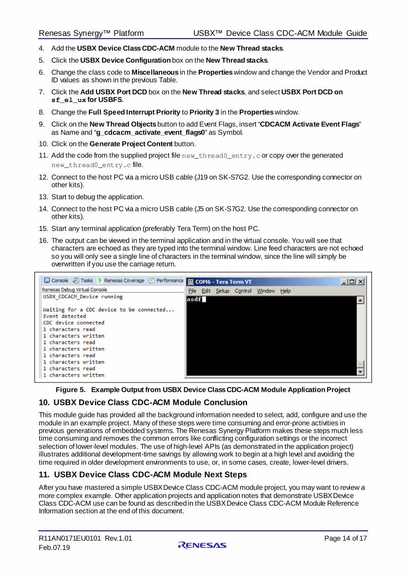
1. Right click on the Unknown device in Device manager and select Update Driver Software... 2. Select Browse my computer for driver software 3. Select Let me pick from a list of device drivers on my computer 4. Scroll down and select Ports (COM & LPT) and click Next
5. Click on Have Disk... 6. When the Install From Disk dialog box comes up, browse to the folder that holds the .inf file
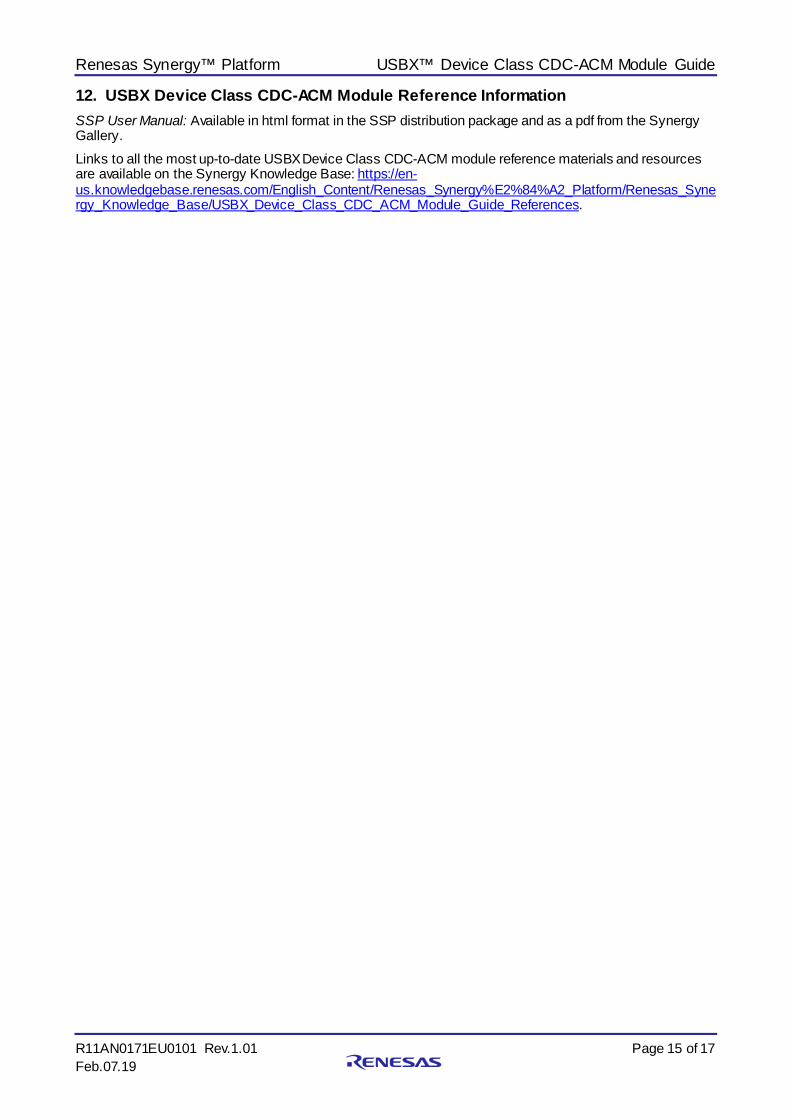
(SynergyUSBCDC.inf), select the file and click Open, then OK. 7. The signed driver should show up in the Model list as Synergy USB CDC/ACM. Click Next. 8. Ignore any warnings and continue to install the driver. 9. The driver should now be installed and will show up in the Ports (COM & LPT) list as seen below.
9.2 Implementing the Application Project in a New Project To implement the USBX Device Class CDC-ACM Module application in a new project, follow the steps for defining, configuring, auto-generating files, adding code, compiling, and debugging in the target kit. Following these steps is a hands-on approach that can help make the development process with SSP more practical, while just reading over this guide will tend to be more theoretical. Note: The following steps are described in sufficient detail for someone experienced with the basic flow
through the Synergy development process. If these steps are not familiar, refer to the first few chapters of the SSP User’s Manual for a description of how to accomplish these steps.
To create and run the USBX Device Class CDC-ACM application project, simply follow these steps: 1. Create a new Renesas Synergy project for the S7G2-SK called USBX_CDCACM_Device.
2. Select the Threads tab. 3. Add the new _thread0 to Threads.
Renesas Synergy™ Platform USBX™ Device Class CDC-ACM Module Guide
R11AN0171EU0101 Rev.1.01 Page 14 of 17 Feb.07.19
4. Add the USBX Device Class CDC-ACM module to the New Thread stacks. 5. Click the USBX Device Configuration box on the New Thread stacks. 6. Change the class code to Miscellaneous in the Properties window and change the Vendor and Product
ID values as shown in the previous Table. 7. Click the Add USBX Port DCD box on the New Thread stacks, and select USBX Port DCD on
sf_el_ux for USBFS.
8. Change the Full Speed Interrupt Priority to Priority 3 in the Properties window. 9. Click on the New Thread Objects button to add Event Flags, insert “CDCACM Activate Event Flags”
as Name and “g_cdcacm_activate_event_flags0” as Symbol. 10. Click on the Generate Project Content button. 11. Add the code from the supplied project file new_thread0_entry.c or copy over the generated
new_thread0_entry.c file.
12. Connect to the host PC via a micro USB cable (J19 on SK-S7G2. Use the corresponding connector on other kits).
13. Start to debug the application. 14. Connect to the host PC via a micro USB cable (J5 on SK-S7G2. Use the corresponding connector on
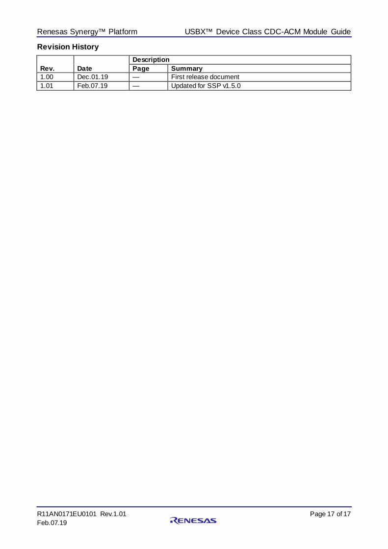
other kits). 15. Start any terminal application (preferably Tera Term) on the host PC. 16. The output can be viewed in the terminal application and in the virtual console. You will see that
characters are echoed as they are typed into the terminal window. Line feed characters are not echoed so you will only see a single line of characters in the terminal window, since the line will simply be overwritten if you use the carriage return.
Figure 5. Example Output from USBX Device Class CDC-ACM Module Application Project
10. USBX Device Class CDC-ACM Module Conclusion This module guide has provided all the background information needed to select, add, configure and use the module in an example project. Many of these steps were time consuming and error-prone activities in previous generations of embedded systems. The Renesas Synergy Platform makes these steps much less time consuming and removes the common errors like conflicting configuration settings or the incorrect selection of lower-level modules. The use of high-level APIs (as demonstrated in the application project) illustrates additional development-time savings by allowing work to begin at a high level and avoiding the time required in older development environments to use, or, in some cases, create, lower-level drivers.
11. USBX Device Class CDC-ACM Module Next Steps After you have mastered a simple USBX Device Class CDC-ACM module project, you may want to review a more complex example. Other application projects and application notes that demonstrate USBX Device Class CDC-ACM use can be found as described in the USBX Device Class CDC-ACM Module Reference Information section at the end of this document.
Renesas Synergy™ Platform USBX™ Device Class CDC-ACM Module Guide
R11AN0171EU0101 Rev.1.01 Page 15 of 17 Feb.07.19
12. USBX Device Class CDC-ACM Module Reference Information SSP User Manual: Available in html format in the SSP distribution package and as a pdf from the Synergy Gallery. Links to all the most up-to-date USBX Device Class CDC-ACM module reference materials and resources are available on the Synergy Knowledge Base: https://en-us.knowledgebase.renesas.com/English_Content/Renesas_Synergy%E2%84%A2_Platform/Renesas_Synergy_Knowledge_Base/USBX_Device_Class_CDC_ACM_Module_Guide_References.

Renesas Synergy™ Platform USBX™ Device Class CDC-ACM Module Guide
R11AN0171EU0101 Rev.1.01 Page 16 of 17 Feb.07.19
Website and Support Visit the following URLs to learn about key elements of the Synergy Platform, download components and related documentation, and get support.
Synergy Software www.renesas.com/synergy/software Synergy Software Package www.renesas.com/synergy/ssp Software add-ons www.renesas.com/synergy/addons Software glossary www.renesas.com/synergy/softwareglossary
Development tools www.renesas.com/synergy/tools
Synergy Hardware www.renesas.com/synergy/hardware Microcontrollers www.renesas.com/synergy/mcus MCU glossary www.renesas.com/synergy/mcuglossary Parametric search www.renesas.com/synergy/parametric
Kits www.renesas.com/synergy/kits
Synergy Solutions Gallery www.renesas.com/synergy/solutionsgallery Partner projects www.renesas.com/synergy/partnerprojects
Application projects www.renesas.com/synergy/applicationprojects Self-service support resources:
Documentation www.renesas.com/synergy/docs Knowledgebase www.renesas.com/synergy/knowledgebase Forums www.renesas.com/synergy/forum Training www.renesas.com/synergy/training Videos www.renesas.com/synergy/videos Chat and web ticket www.renesas.com/synergy/resourcelibrary
Renesas Synergy™ Platform USBX™ Device Class CDC-ACM Module Guide
R11AN0171EU0101 Rev.1.01 Page 17 of 17 Feb.07.19
Revision History
Rev. Date Description Page Summary
1.00 Dec.01.19 — First release document 1.01 Feb.07.19 — Updated for SSP v1.5.0
© 2019 Renesas Electronics Corporation. All rights reserved.
Notice 1. Descriptions of circuits, software and other related information in this document are provided only to illustrate the operation of semiconductor products
and application examples. You are fully responsible for the incorporation or any other use of the circuits, software, and information in the design of your product or sy stem. Renesas Electronics disclaims any and all liability for any losses and damages incurred by you or third parties arising from the use of these circuits, software, or information.
2. Renesas Electronics hereby expressly disclaims any warranties against and liability for infringement or any other claims involving patents, copyrights, or other intellectual property rights of third parties, by or arising from the use of Renesas Electronics products or technical information described in this document, including but not limited to, the product data, drawings, charts, programs, algorithms, and application examples.
3. No license, express, implied or otherwise, is granted hereby under any patents, copyrights or other intellectual property rights of Renesas Electronics or others.
4. You shall not alter, modify, copy, or reverse engineer any Renesas Electronics product, whether in whole or in part. Renesas Electronics disclaims any and all liability for any losses or damages incurred by you or third parties arising from such alteration, modification, copying or reverse engineering.
5. Renesas Electronics products are classified according to the following two quality grades: “Standard” and “High Quality”. The intended applications for each Renesas Electronics product depends on the product’s quality grade, as indicated below. "Standard": Computers; office equipment; communications equipment; test and measurement equipment; audio and visual equipment; home
electronic appliances; machine tools; personal electronic equipment; industrial robots; etc. "High Quality ": Transportation equipment (automobiles, trains, ships, etc.); traffic control (traffic lights); large-scale communication equipment; key
f inancial terminal systems; safety control equipment; etc. Unless expressly designated as a high reliability product or a product for harsh environments in a Renesas Electronics data sheet or other Renesas Electronics document, Renesas Electronics products are not intended or authorized for use in products or systems that may pose a direct threat to human lif e or bodily injury (artificial life support devices or systems; surgical implantations; etc.), or may cause serious property damage (space sy stem; undersea repeaters; nuclear power control systems; aircraft control systems; key plant systems; military equipment; etc.). Renesas Electronics disclaims any and all liability for any damages or losses incurred by you or any third parties arising from the use of any Renesas Electronics product that is inconsistent with any Renesas Electronics data sheet, user’s manual or other Renesas Electronics document.
6. When using Renesas Electronics products, refer to the latest product information (data sheets, user’s manuals, application notes, “General Notes for Handling and Using Semiconductor Devices” in the reliability handbook, etc.), and ensure that usage conditions are within the ranges specified by Renesas Electronics with respect to maximum ratings, operating power supply voltage range, heat dissipation characteristics, installation, etc. Renesas Electronics disclaims any and all liability for any malfunctions, failure or accident arising out of the use of Renesas Electronics products outside of such specif ied ranges.
7. Although Renesas Electronics endeavors to improve the quality and reliability of Renesas Electronics products, semiconductor products have specific characteristics, such as the occurrence of failure at a certain rate and malfunctions under certain use conditions. Unless designated as a high reliability product or a product for harsh environments in a Renesas Electronics data sheet or other Renesas Electronics document, Renesas Electronics products are not subject to radiation resistance design. You are responsible for implementing safety measures to guard against the possibility of bodily injury , injury or damage caused by fire, and/or danger to the public in the event of a failure or malfunction of Renesas Electronics products, such as saf ety design for hardware and software, including but not limited to redundancy, fire control and malfunction prevention, appropriate treatment for aging degradation or any other appropriate measures. Because the evaluation of microcomputer software alone is very difficult and impractical, you are responsible f or evaluating the safety of the final products or systems manufactured by you.
8. Please contact a Renesas Electronics sales office for details as to environmental matters such as the environmental compatibility of each Renesas Electronics product. You are responsible for carefully and sufficiently investigating applicable laws and regulations that regulate the inclusion or use of controlled substances, including without limitation, the EU RoHS Directive, and using Renesas Electronics products in compliance with all these applicable laws and regulations. Renesas Electronics disclaims any and all liability for damages or losses occurring as a result of your noncompliance with applicable laws and regulations.
9. Renesas Electronics products and technologies shall not be used for or incorporated into any products or systems whose manufacture, use, or sale is prohibited under any applicable domestic or foreign laws or regulations. You shall comply with any applicable export control laws and regulations promulgated and administered by the governments of any countries asserting jurisdiction over the parties or transactions.
10. It is the responsibility of the buyer or distributor of Renesas Electronics products, or any other party who distributes, disposes of, or otherwise sells or transf ers the product to a third party, to notify such third party in advance of the contents and conditions set forth in this document.
11. This document shall not be reprinted, reproduced or duplicated in any form, in whole or in part, without prior written consent of Renesas Electronics. 12. Please contact a Renesas Electronics sales office if you have any questions regarding the information contained in this document or Renesas
Electronics products. (Note1) “Renesas Electronics” as used in this document means Renesas Electronics Corporation and also includes its directly or indirectly controlled
subsidiaries. (Note2) “Renesas Electronics product(s)” means any product developed or manufactured by or for Renesas Electronics.
(Rev .4.0-1 November 2017)
Corporate Headquarters Contact information TOYOSU FORESIA, 3-2-24 Toyosu, Koto-ku, Tokyo 135-0061, Japan www.renesas.com
For f urther information on a product, technology, the most up-to-date v ersion of a document, or your nearest sales office, please visit: www.renesas.com/contact/.
Trademarks Renesas and the Renesas logo are trademarks of Renesas Electronics Corporation. All trademarks and registered trademarks are the property of their respective owners.