use and maintenance manual cartoni non int - u… · rod fastening nut. cylinder fastening nut....
TRANSCRIPT

USE AND MAINTENANCE MANUAL
UM-Z-2010-R0 1
CLAMP FOR APPLIANCES INTRODUCTION This manual contains instructions for assembly, periodic and extraordinary maintenance and troubleshooting. The instructions in this manual supplement, and do not replace, the obligation to obey occupational safety and accident-prevention laws, which is the user company's responsibility. The
user company is, likewise, required to follow all the instructions in this manual, including training its 1personnel to use and maintain the attachment. SPECIFICATIONS AND USE OF THE ATTACHMENT Attachment, to be hooked to a forklift truck, for handling cardboard packaging boxes. It consists of a jaw guide frame complete with hooks with ISO 2328 profile for fastening to the truck,
with or without side shifting; a hydraulic power plant adequate for the needs of the specific handling, shifting of the load obtained with valves, jaw synchronisation, load tightening pressure adjusting system, tightening pressure gauge indicator, jaws equipped with oscillating panel support, panel equipped with vulcanized rubber handling runner, having shape and size suitable for the load to be handled, jaws motion driven by opposing linear actuators, load supporting grid.
USED SYMBOLS INDEX PART 1: FIXING TO THE TRUCK AND ADJUSTMENTS
1. RECOMMENDATIONS FOR USING THE EQUIPMENT Page 2 7. CHECKS AND ADJUSTMENTS Page 7
1.1. PROHIBITED MOVEMENTS Page 2 7.1. CLAMPING PRESSURE Page 7
1.2. CORRECT MOVEMENTS Page 2 7.2. SPEED AND SYNCHRONISM Page 7
2. FORKLIFT CHECKS Page 3 7.3. JAWS ADJUSTMENT Page 8
3. ATTACHMENT CONFIGURATION Page 3 7.3. 1. ADJUSTING THE PANEL SUPPORTS Page 8
3.1. FOR SHIPPING Page 3 7.3. 2. PANEL SUPPORTS TILTING ADJUSTMENT Page 8
4. ATTACHMENT DESCRIPTION Page 4 8. DAILY CHECKS Page 8
4.1. WITH/WITHOUT INCORPORATED SHIFTING Page 4
5. FIXING TO THE TRUCK Page 4
5.1. PREPARATION Page 4
5.2. FASTENING LOWER HOOKS Page 4
5.3. JAWS HOOKING Page 5
5.4. HOOK ADJUSTMENT Page 5
5.5. CONNECTING HOSES Page 5
6. HYDRAULIC POWER PLANT CONNECTION AND DIAGRAM Page 6
6.1. MOVEMENT CHECK Page 6
6.2.1. WITHOUT SHIFTING Page 6
6.2.2. WITH INCORPORATED SHIFTING Page 6
ORIGINAL
Situation with possible risks for the operator's safety.
Procedure that must be performed.
Notes to read carefully.

USE AND MAINTENANCE MANUAL
UM-Z-2010-R0 2
PART 2: MAINTENANCE
1. RECOMMENDATIONS FOR USING THE EQUIPMENT
1.1. PROHIBITED MOVEMENTS 1.2. CORRECT MOVEMENTS
9. REGULAR MAINTENANCE Page 9 10. EXTRAORDINARY MAINTENANCE Page 10 10.1. PANEL DISASSEMBLING Page 10 10.2. PANEL SUPPORT DISASSEMBLING Page 10 10.3. JAW DISASSEMBLING Page 11 10.4. SLIDE BLOCK DISASSEMBLY Page 11 10.5. SLIDE BLOCK REPLACEMENT Page 12 10.6. CYLINDER ROD FASTENING Page 12 10.7. CYLINDER BOX FASTENING Page 12 10.8. CYLINDER DISASSEMBLY Page 12 10.8.1 GASKET REPLACEMENT Page 12 10.8.2 GASKET ASSEMBLY Page 12 10.9. VALVE DISASSEMBLY Page 13 10.10. LOAD SUPPORTING GRID Page 13 11. TROUBLESHOOTING Page 14 12. NOISE Page 15 13. RECYCLING Page 15 14. WARRANTY Page 15
15. CERTIFICATE OF CONFORMITY (FACSIMILE) Page 15
Transporting an unstable or unbalanced load; too bulky, reducing visibility; of weight greater than the indicated capacity; moving an already deposited load using the load to be deposited; using the attachment when it presents structural deformations or operating anomalies.
Proceeding at high speed on a rough surface or climbing ramps.
Transporting persons or performing manoeuvres with persons in the radius of action
Parking the truck with motor running and/or load lifted on a rough surface or on climbing ramps.
Executing movements or manoeuvres with load raised to a high level.
When moving with the truck, keep the mast tilted (the point of the forks high), the load lifted slightly from the ground and centred, adjusting the speed based on the road surface and any obstacles or presence of persons on the rout.
The load must be stable, or tied with crossed layers or tied with straps.
Be careful when gripping the load to avoid damage or dangerous movements of the adjacent cardboard boxes.
Avoid gripping boxes with just the point of the jaws. If this manoeuvre is necessary, do not tighten at full power. Handling loads whose height can interfere with visibility during the manoeuvre.

USE AND MAINTENANCE MANUAL
UM-Z-2010-R0 3
2. FORKLIFT CHECKS
3. ATTACHMENT CONFIGURATION
3.1. FOR SHIPPING
Document
The recommended diameter for any additional power plant is 9.5 mm.
Distributor with no. 4 levers for controlling motions .
The fork placement notches must be in good condition and not clogged.
Identification plate.
Belt fixing the attachment to the pallet.
The attachment is protected by a heat-shrink covering.
ISO 2228 Dimension “A” (mm): Classe I = min. 304 – max. 305 Classe II = min. 380 - max. 381 Classe III = min. 474.5 – max. 476 Classe IV = min. 595,5 – max. 597
DO NOT USE THE ATTACHMENT FOR ANY PURPOSE OR MOVEMENT OTHER THAN INDICATED.
THE EFFECTIVE CAPACITY OF THE COMBINATION OF THE TR UCK AND THE ATTACHMENT IS THE RESPONSIBILITY OF THE MANUFACTURER OF THE TRUCK AND MAY NOT CORRESPON D TO WHAT IS SPECIFIED ON THE IDENTIFICATION PLATE. CONTACT THE MANUFACTURER OF THE TRUCK FOR I TS DEFINITIVE CAPACITY.
Pallet for transport.
The fork-holder plate must be flat and without front projections.
When checked at the distributor, the truck's hydraulic pump must have a maximum pressure of 25 MPa and a flow-capacity of 20 - 25 l/m’.
Accident-prevention

USE AND MAINTENANCE MANUAL
UM-Z-2010-R0 4
ATTACHMENT DESCRIPTION
4.1. WITH/WITHOUT INCORPORATED SHIFTING
5. FIXING TO THE TRUCK
5.1. PREPARATION 5.2. FASTENING LOWER HOOKS
Wrench size and screw tightening.
FEM class.
Wrench mm
Tightening N/m
2 22 120
Lower ISO 2328 locking hooks
Upper ISO 2328 hooks.
Central reference and stop for lateral sliding. Fixed frame.
Power input for opening and closing jaws.
1) Remove the Nylon protection and the pallet fastening belts.
3) Disconnect the lower jaws. ISO 3318
Use an ISO 3318 wrench to fasten the lower jaws.
Only with incorporated shifting: power input for incorporated side shifting. Valve block.
Hook control linear actuator.
Hydraulic power
2) Fasten no. 2 eyebolts to the ends of the frame.
4) Use cables with UNI ISO 4479 hooks and straps to lift the attachment.
Manometer connection to check pressure.
5) Hook the attachment to the truck so that the central stop engages the central notch of the fork-holder plate.
USE AND MAINTENANCE MANUAL
UM-Z-2010-R0 5
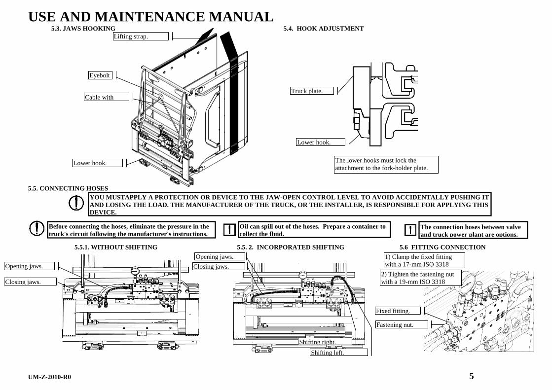
5.3. JAWS HOOKING 5.4. HOOK ADJUSTMENT
5.5. CONNECTING HOSES
5.5.1. WITHOUT SHIFTING 5.5. 2. INCORPORATED SHIFTING 5.6 FITTING CONNECTION
Oil can spill out of the hoses. Prepare a container to collect the fluid.
Before connecting the hoses, eliminate the pressure in the truck's circuit following the manufacturer's instru ctions.
The connection hoses between valve and truck power plant are options.
The lower hooks must lock the attachment to the fork-holder plate.
Shifting right.
Shifting left.
Closing jaws.
Opening jaws. Closing jaws.
Opening jaws.
Fixed fitting.
Fastening nut.
1) Clamp the fixed fitting with a 17-mm ISO 3318
2) Tighten the fastening nut with a 19-mm ISO 3318
Truck plate.
Lower hook.
Eyebolt
Lower hook.
Cable with
Lifting strap.
YOU MUSTAPPLY A PROTECTION OR DEVICE TO THE JAW- OPEN CONTROL LEVEL TO AVOID ACCIDENTALLY PUSHING IT AND LOSING THE LOAD. THE MANUFACTURER OF THE TRUCK, OR THE INSTALLER, IS RESPONSIBLE FOR APPLYING THIS DEVICE.

USE AND MAINTENANCE MANUAL
UM-Z-2010-R0 6
6. HYDRAULIC POWER PLANT CONNECTION AND DIAGRAM 6.1. MOVEMENT CHECK
6.2. 1. WITHOUT SHIFTING
6.2.2. WITH SHIFTING
INCORPORATED
7. CHECKS AND ADJUSTMENTS
1st lever (lifting).
2nd lever (tilting). Before connecting the hoses, eliminate the pressure in the truck's circuit following the manufacturer's instru ctions.
Oil can spill out of the hoses. Prepare a container to collect the fluid.
4th
Existing power plant on the truck.
4th
Existing power plant on the truck.
To check the connections, perform 5 complete movements without and with a
3rd 4th
YOU MUSTAPPLY A PROTECTION OR DEVICE TO THE JAW-OPE N CONTROL LEVEL TO AVOID ACCIDENTALLY PUSHING IT AND LOSING THE LOAD. THE MANUFACTURER OF THE TRUCK, OR THE INSTALLER, IS RESPONSIBLE FOR APP LYING THIS DEVICE.
3rd

USE AND MAINTENANCE MANUAL
UM-Z-2010-R0 7
7.1. CLAMPING PRESSURE 7.2. SPEED AND SYNCHRONISM
Before connecting the hoses, eliminate the pressure in the truck's circuit following the manufacturer's instru ctions.
The valves are preset and checked during final acceptance testing with in-house controllers. Perform the indicated checks/adjustments if there are anomalies, loss of load or lack of synchronism of the jaws.
With the application of the manometer, you only check/record the pressure in the hydraulic circuit for the gripping of the load
Take the manometer reading with the attachment at its minimum opening.
The maximum pressure, which must not be exceeded, is indicated on
Remove the protection with a 24-mm ISO 3318 wrench; loosen the lock nut with a 17-mm ISO 3318 wrench; make the adjustment with a 5-mm ISO 3926 wrench, tightening to increase the pressure; tighten the lock nut.
To restore the synchronism, adjust the cylinder of the slow jaw to avoid a reduction of the total closing speed. A speed difference of 10% of the travel is allowed between the jaws.
Loosen the lock nut with a 13-mm ISO 3318 wrench, open the screw by 90° with a 4-mm ISO 3926 wrench and check the results; repeat the adjustment until the desired result is obtained. At the end of adjustment, tighten the lock nut.
Contact the post-sales support office before adjusting the tightening pressure.
The protection of the regulator valve is an anti-tampering safety feature. The manufacturer will not be liable for damage or breakage if not contacted before any adjustments.
USE AND MAINTENANCE MANUAL
UM-Z-2010-R0 8
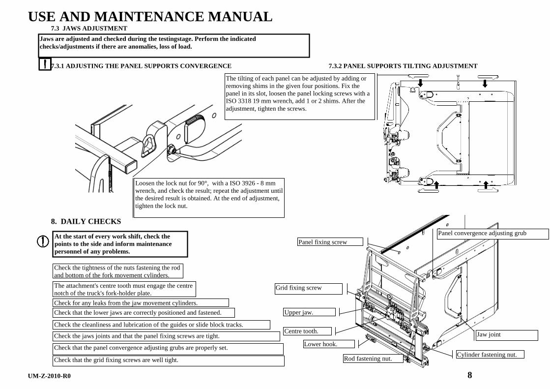
7.3 JAWS ADJUSTMENT
7.3.1 ADJUSTING THE PANEL SUPPORTS CONVERGENCE 7.3.2 PANEL SUPPORTS TILTING ADJUSTMENT
8. DAILY CHECKS
At the start of every work shift, check the points to the side and inform maintenance personnel of any problems.
Check the tightness of the nuts fastening the rod and bottom of the fork movement cylinders.
The attachment's centre tooth must engage the centre notch of the truck's fork-holder plate.
Check for any leaks from the jaw movement cylinders.
Check that the lower jaws are correctly positioned and fastened.
Rod fastening nut. Cylinder fastening nut.
Upper jaw.
Centre tooth.
Lower hook.
Check the cleanliness and lubrication of the guides or slide block tracks.
Jaw joint
Panel fixing screw
Check the jaws joints and that the panel fixing screws are tight.
Check that the panel convergence adjusting grubs are properly set.
Check that the grid fixing screws are well tight.
Grid fixing screw
Panel convergence adjusting grub
Jaws are adjusted and checked during the testingstage. Perform the indicated checks/adjustments if there are anomalies, loss of load.
Loosen the lock nut for 90°, with a ISO 3926 - 8 mm wrench, and check the result; repeat the adjustment until the desired result is obtained. At the end of adjustment, tighten the lock nut.
The tilting of each panel can be adjusted by adding or removing shims in the given four positions. Fix the panel in its slot, loosen the panel locking screws with a ISO 3318 19 mm wrench, add 1 or 2 shims. After the adjustment, tighten the screws.

USE AND MAINTENANCE MANUAL
UM-Z-2010-R0 9
9. REGULAR MAINTENANCE
PERIODIC MAINTENANCE DIAGRAM
OPERATIONS Hours of work
Clamp for appliances Clean and grease jaw-sliding “a” guides.
200 Check screw tightness and oil leaks from the hydraulic connections. Check that the nameplates and safety stickers in “c” are easy to read.
In addition to the operations for every 200 working hours, do the following: Check slide blocks “b” and replace if necessary.
1000 Check the tightening pressure and synchronism of the jaws. Check the condition of the flexible hoses and fittings. Check hydraulic actuators “d”; check for oil leaks from the plug and the condition of the chromium plated rod surface. Check the wear on the clamping surface of the panels. Check the panel “g” support joint.
In addition to the operations for every 200 and 1000 working hours, do the following: In the area “f”, check for wear on the parts sliding on the ground.
2000 Check the integrity of jaw-fastening base “e”. Look for deformations or breakage in the structure or welds.
Recommended Lubricants: For insides: ISO X M2 (SHELL ALVANIA GREASE R2). Outsides: ISO CB 32 (ESSO
IF THE EQUIPMENT IS USED IN DUSTY, HUMID OR CORROSI VE ENVIRONMENTS, WE RECOMMEND HALVING THE HOURS OF WOR K.
Before connecting-disconnecting the hoses, eliminate the pressure in the truck circuit following the manufacturer's instructions.

USE AND MAINTENANCE MANUAL
UM-Z-2010-R0 10
10. EXTRAORDINARY MAINTENANCE
10.1. PANEL DISASSEMBLING 10.2 PANEL SUPPORT DISASSEMBLING
Use the slot in the upper part of the panel for the hook.
Attachment fixed to the truck or positioned so that the panel can be removed.
2) Remove the panel from its support by means of a torque wrench ISO 1174 - 19 mm, loosen the 8 screws after having attached the panel in its slot. pannello nell’apposita asola.
1) Bring the jaws to their maximum opening.
Equipment fixed to the fork lift or positioned in such way to remove the panel support. To remove the support, the panel must be removed in advance.
2) Remove the cover of the panel joining pins, by removing the screws with a ISO 3926 3 mm wrench.
3) Remove the pin fixing blocks, removing theirs screws with an ISO 3926 - 5 mm wrench. Remove the panel joining pins.
4) Now the panel support can be removed.
1) Attach the support fixing a hook/eyebolt in its bores.
Use the hole in the upper part of the support to apply the lifting strap.
Cover of the panel joining pins
Pin fixing block
Joining pin
Panel fixing screws.

USE AND MAINTENANCE MANUAL
UM-Z-2010-R0 11
10.3. JAW DISASSEMBLING
10.4. SLIDE BLOCK DISASSEMBLY
2) Disconnect the jaw from the cylinder using a 22-mm ISO 3318 wrench to clamp the rod and a 30-mm ISO 1174 socket wrench to unscrew the
4) Take the jaw out by the side, and lay it on the ground.
2) Using an 8-mm DIN 6450 punch, unlock the slide blocks and slide them off of the guide.
For the front slide blocks of the jaw use an ISO 2380 screwdriver because there are no release holes.
Slide block stop.
The balance of the jaw or fork becomes unstable when not guided by the frame.
TO PUT BACK THE DISASSEMBLED PARTS, PERFORM THE PRO CEDURE DESCRIBED ABOVE IN REVERSE.
Attachment fixed to the truck or positioned so that you can move the jaws hydraulically.
1) Bring the jaws to their maximum opening.
3) Bring the cylinders to their minimum closure, supporting the upper cylinder.
1) Remove the screws, with a ISO 3926 4 mm wrench and remove the slide block.
Slide block stop fastening
Front slide block
TO PUT BACK THE DISASSEMBLED PARTS, PERFORM THE PRO CEDURE DESCRIBED ABOVE IN REVERSE.
Position the stop correctly when mounting the new slide blocks.
Use the slot in upper part of the jaw to attach the hook.

USE AND MAINTENANCE MANUAL
UM-Z-2010-R0 12
10.5. SLIDE BLOCK REPLACEMENT 10.6. CYLINDER ROD FASTENING 10.7. CYLINDER BOX FASTENING
10.8. CYLINDER DISASSEMBLY
10.8.1. GASKET REPLACEMENT
10.8.2. GASKET ASSEMBLY
Tighten the nut until the Bellevue spring is locked and tighten 90°.
1) With the clamp at its minimum opening, position the jaw at an opening of 500 mm.
3) Disconnect the cylinders from the jaws using a 22-mm ISO 3318 wrench to clamp the rod and a 30-mm ISO 1174 socket wrench to unscrew the nut.
4) Bring the cylinders to their minimum
6) Use a 30-mm socket wrench to unscrew the bottom-side nut and remove the cylinder.
5) Disconnect the flexible hoses from the cylinders with a 19-mm ISO 3318
Replace the slides if broken, bent or if their thickness is lower than S1 4 mm; S2 5 mm.
Oil can spill out of the hoses. Prepare a container to collect the fluid.
Check that the shock absorber is perfectly inserted in its seat and tighten until the cylinder is locked.
Vibration damper.
2) Use a 19-mm ISO 3318 wrench to replace the copper seal washer.
1) To replace the “OR” gasket seal inside the regulator, use a 13-mm ISO 3318 wrench and 4-mm ISO3926 wrench.
3) Use a 12-60-mm spanner wrench and 4-mm-diameter pin to remove the cylinder plug.
When replacing the gaskets, taken care to match the mounting direction and work in an area protected from dust.
Cylinder bottom.
Before connecting-disconnecting the hoses, eliminate the pressure in the truck circuit following the manufacturer's
Scudo protezione cilindro. Cylinder rod.
Copper washer.
Flow-capacity
Cylinder plug.
2) Remove the fixing screws of the cylinders protection shield by means of a bush wrench ISO 1174 19 mm, and remove shield.
Attachment fixed to the truck or positioned so that you can move the jaws hydraulically.

USE AND MAINTENANCE MANUAL
UM-Z-2010-R0 13
10.9. VALVE DISASSEMBLY
10.10. LOAD SUPPORTING GRID
Oil can spill out of the hoses. Prepare a container to collect the fluid.
You must disconnect the attachment from the truck to remove the valve.
3) Fasten no. 2 eyebolts to the ends of the
5) Disconnect the flexible hoses from the valve with a 19-mm ISO
6) Disconnect the valve block using a 6-mm ISO 3926
TO PUT BACK THE DISASSEMBLED PARTS, PERFORM THE PRO CEDURE DESCRIBED ABOVE IN
Eyebolt.
1) Dismount the lower hooks with an ISO 3318 wrench.
4) Using UNI ISO 4479 hooks with cables, lift the attachment and rest it on the ground.
Valve block.
Cable with lifting hooks.
Lower hook.
2) Disconnect the flexible power hoses from the valve with a 19-mm ISO 3318 wrench.
TO PUT BACK THE DISASSEMBLED PARTS, PERFORM THE PRO CEDURE DESCRIBED ABOVE IN
1) Hook the grid by means of lifting cables.
2) Remove the load supporting grid fixing screws, by means of an ISO 3318 22 mm wrench
3) Now the grid can be removed and laid on the ground. Load supporting grid fixing screw
Lifting strap.

USE AND MAINTENANCE MANUAL
UM-Z-2010-R0 14
11. TROUBLESHOOTING Clamping force insufficient with slipping or loss of load.
Insufficient oil pressure and/or flow. Check and/or adjust the hydraulic pump and oil level in the tank of the truck. Check and adjust the attachment's valve.
Residual air in the hydraulic circuit. Check the oil level in the forklift's tank. Remove the residual air in the circuit. Hydraulic pump worn. Replace the truck's hydraulic pump. Obstruction or leaks in the hydraulic circuit. Check the hoses and connections of the hydraulic power plant of the truck-attachment;
remove the obstructions or leaks, replacing damaged hoses. Oil oozing in cylinders or valve. Replace the cylinder gaskets or replace the valve. Surface of the panel, in contact with the load, worn. Restore the initial state of the surface or replace the panel. Incorrect jaws alignment/tilting. Modify the jaws alignment/tilting, as given in “JAWS ADJUSTMENT”.
Load damaged after clamping. Pressure limiting valve with adjusted to excessive force. Check and adjust valve. Pressure limiting valve malfunction. Replace valve. Surface of the jaw, in contact with the load, worn. Restore the initial state of the surface or replace the jaw. Incorrect jaws alignment/tilting. Modify the jaws alignment/tilting, as given in “JAWS ADJUSTMENT”.
The jaws close or open slowly or irregularly.
Insufficient oil pressure and/or flow. Check and/or adjust the hydraulic pump and oil level in the tank of the truck. Check and adjust the attachment's valve.
Residual air in the hydraulic circuit. Check the oil level in the forklift's tank. Remove the residual air in the circuit. Hydraulic pump worn. Replace the truck's hydraulic pump. Obstructions or breakage in the hydraulic circuit. Remove the obstruction or replace the damaged hose. Oil oozing in cylinders or valve. Replace the cylinder gaskets or replace the valve. Excessive friction between the sliding guides. Clean and grease. Check the integrity of the guides and remove any deformations. Check
and/or replace the slide blocks. Flow-capacity limiter of the cylinder closed too much. Adjust as shown in the point “SPEED AND SYNCHRONISM” Regeneration circuit not adjusted. Adjust as shown in the point “SPEED AND SYNCHRONISM”
Side shifting slow, irregular or blocked.
Insufficient oil pressure and/or flow. Check and/or adjust the hydraulic pump and oil level in the tank of the truck. Check and adjust the attachment's valve.
Residual air in the hydraulic circuit. Check the oil level in the forklift's tank. Remove the residual air in the circuit. Hydraulic pump worn. Replace the truck's hydraulic pump. Obstructions or breakage in the hydraulic circuit. Remove the obstruction or replace the damaged hose. Oil oozing in cylinders or valve. Replace the cylinder gaskets or replace the valve. Excessive friction between the sliding guides. Check the slide blocks, the integrity of the guides, remove any deformations, clean and
grease. Flow-capacity limiter of the cylinder closed too much. Adjust as shown in the point “SPEED AND SYNCHRONISM”
IN CASE OF PROBLEMS NOT DESCRIBED ABOVE, CONTACT OU R SERVICE DEPARTMENT

USE AND MAINTENANCE MANUAL
UM-Z-2010-R0 15
12. NOISE 13. RECYCLING
Disposal of replaced parts must carried out in the same way of a full scrapping, separating them according to the nature of their materials and complying with laws governing the disposal
of solid industrial waste. NOTE: Pieces not listed in the table to the side are steel.
14. WARRANTY 15. FACSIMILE OF CERTIFICATE O F CONFORMITY
The manufacturer warrants all its products for 12 months or 2000 working hours (whichever comes first) from the date of shipment. If used for more than 8 hours per day, the warranty period will be reduced proportionally. The guarantee is limited to the replacement, carriage forwards manufacturer plant of those parts the same manufacturer recognises to be defective owing to material or processing faults and does not include the labour cost or transfer cost for the replacement of such parts. In addition, it is understood that the warranty is void if the problem is due to inappropriate use of the product, if it was not put into service following the manufacturer's instructions or if other than original replacement parts were used for modifications and/or repairs. The attachment is not warranted for uses that exceed the capacities shown on the plate and in the documentation. All attachments are covered by insurance against any damage to third parties caused by defective pieces or their incorrect functioning; any damage caused by incorrect or improper use is excluded.
Pallet for transport Wood
Belts for fixing and protective covering for shipping
Polyester and heat-shrink
Cylinder plugs Cast iron Guide slide blocks Nylon
Pipes/fittings Polyester/steel
Gaskets Polyurethane and NBR Paint Polyester epoxy Gearmotor and grease Dispose of in conformity with local law
THE SPECIFICATIONS THAT FOLLOW APPLY TO THE TRUCK-ATTACHMENT UNIT.
- Acoustic pressure level of the weighted emission A in the work place, if it exceeds 70 dB(A); if this level does not exceed 70 dB(A), it must be indicated. -The maximum value of the instantaneous weighted acoustic pressure C in the work place, if it exceeds 63 Pa (130 dB with respect to 20 µPa). -Weighted acoustic power level A emitted by the machine, if the weighted acoustic pressure level A in the work place exceeds 80 dB(A).