use instuctions - flowserve · use instuctions experience in motion valtek s general service...
TRANSCRIPT

USER INSTRUCTIONS
Experience in Motion
Valtek GS General Service Control ValveFCD VLENIM0300-00-AQ 08/14
InstallationOperation
Maintenance
TUV Certified IOM

Valtek GS General Service Valve FCD VLENIM0300-00-AQ 08/14
2
General Service Control Valve - Valtek GSThe Valtek GS product line is low cost, compact and light-weight. Yet, it is rug-ged and can be used safely and confidently in a wide range of general service applications plant-wide. Its modular design provides trim and material options to suit most service situations. Simplicity of design reduces maintenance and parts inventory costs. It is ideally suited for flow and pressure control of liquid and gas media in oil and gas, power, chemical and petrochemical processing and related in-dustries. The Valtek GS control valve package provides flow rates, control accuracy and reliability at levels comparable to special engineered service control valves, but at a significantly lower cost. The Valtek GS is manufactured to ISO 9001 standards.
The following instructions are designed to assist in unpacking, installing and per-forming maintenance as required on Flowserve Valtek GS control valves. This in-struction manual does not include specific product design data. Such data can be found on the valve’s serial plate or specification documents; additionally, dimen-sional information can be found in the Valtek GS technical bulletin. Procure needed documents as necessary before you begin any work on the valve.
User Instructions cannot deal with all possible situations and installation options. It is required that only trained and qualified technicians are authorized to adjust, repair or work on control valves, actuators, positioners and other accessories. Review this bulletin prior to installing, operating or performing any maintenance on the valve. Additional Installation, Operation, and Maintenance Instructions (IOMs) cover other features (such as special trim, actuators, handwheels, packing and positioners).
To avoid possible injury to personnel or damage to valve parts, WARNING and NOTICE indicators must be strictly followed. Modifying this product, substituting non-factory parts or using maintenance procedures other than outlined could drastically affect performance and be hazardous to personnel and equipment and may void existing warranties. This manual should be used in conjunction with applicable local and national laws. Failure to comply with User Instructions will render the manufacturer’s guarantee and liability null and void. Unless otherwise agreed, the manufacturer’s general terms and conditions of sale shall apply.
Read the user instructions carefully before use. Keep for future reference.
Contents1 Scope of Manual 3 10 Valve Quick-Check 7 - 8
2 Intended Use 3 11 Valve Maintenance 8 - 10
3 Product Identification 3 12 Troubleshooting 10 - 11
4 Valtek GS Modification 3 - 4 13 Disassembly and Reassembly 12 - 19
5 Safety 4 14 Torque Requirements 20
6 Packaging and Transport 4 15 Lubricants 20
7 Storage 4 16 Special Tools 21
8 Unpacking 4 - 5 17 Parts List 22
9 Installation 5 - 7 18 Disposal 23
Figure 1: Valtek GS with Standard /Extended Bonnet
Figure 2: Valtek GS with Bellows Seal Bonnet

Valtek GS General Service Valve FCD VLENIM0300-00-AQ 08/14
3
flowserve.com
1 Scope of ManualThe following user information covers the Valtek GS general service control valve:
• Metric DIN Units - PN 16 / 40, DN 15 - 150
• English ASME Units - Class 150 / 300, NPS ½ - 6
• Assembled with a pneumatic or electric linear actuator
• Comes with or without ancillary equipment
2 Intended Use
WARNING Control valves are pressure ves-sels designed and rated for spe-
cific application conditions. Before installation, check the serial number and / or the tag number to ensure that the valve and actuator being installed are correct for the in-tended application. Do not use the valve outside of its rated design limits. Exceeding the design limits may cause haz-ardous conditions including leakage of the process media or rupture of the pressure boundary resulting in possible process loss, equipment or environmental damage, or seri-ous personal injury or death.
The specific product design data can be found on the valve’s serial plate, data sheet and the calculation sheet (in acc. to the IEC 60534-7:2010).
The Valtek GS handles a wide variety of general service ap-plications, while offering high flow capacity. All sizes come standard with unbalanced trim; for high pressure drop appli-cations optional pressure balanced trim is available for NPS sizes 3 to 6 (DIN size 80 to 150).
The Valtek GS consists of the body, bonnet, trim, and actuator. The valve is designed with a high level of interchangeability al-lowing the user to assemble the greatest possible number of variations from a minimum number of components to match each application. There are two bonnet designs, standard / extended bonnets and bellows seal bonnets. See Figure 1 and Figure 2.
The Valtek GS is designed in compliance with EN 1349:2009 - Industrial Process Control Valves (DIN EN 1349 and VDE 0409-1349).
The Valtek GS is designed for use in MODERATE and WORLD-WIDE environmental conditions, ambient temperature range
-40°F to 158°F (-40°C to +70°C), air humidity up to 93% non-condensing, air pollution up to 300 µg/m3, unless restricted by the accessories.
The product offering may include optional ancillary equip-ment, such as positioners, air-filter regulators, solenoid valves, limit switches or boosters. Digital, I/P, or pneumatic positioners can be mounted directly, with a mounting bracket or according to NAMUR standards. Refer to the relevant man-ufacturer‘s user instructions for information regarding other ancillary equipment.
3 Product Identification
Each Valtek GS control valve comes with an attached serial plate which includes key information specifically for each con-trol valve:
Figure 3: Serial Plate (WW-design, WorldWide)
Made in Villach - AustriaR
Tag.No.Kennzeichnung
Fabrikations Nr.Serial No.
TypeTyp
DN PN/ClassGehaeuse / Atteste
Body / Certi�cateKegelPlug Seat
SitzKvs / Cv
InnenteileTrim
AntriebActuator S
BetriebstemperaturWorking Temperature
max.
BetriebsdruckWorking Pressure
Characteristic / Stroke
for Actuator
Arrangement
Supply
Sicherheitsstellung< 30°
Druecke sind UeberdrueckePressures are gauge pressures
UmgebungstemperaturAmbient Temperature
max.
min.
Kennlinie / Hub
dp fuer Antrieb
max. Einbaulage
BesonderheitenSpecialities
Zuluft
FederlaufbereichSpring Range
Failure Position
min. / max.
Figure 4: Serial Plate (EU-design, European Union)
The same serial number shown on the plate will appear on all Valtek GS data sheets, dimensional drawings, bills of material, and spare parts lists. Other information located on the serial plate is self-explanatory for the Valtek GS control valve.
You can download .pdf versions of the Valtek GS documenta-tion including a sales brochure, technical bulletin and user instructions at www.flowserve.com. It is the user’s respon-sibility to keep this and related documentation on file and ac-cessible for the Valtek GS product.
4 Valtek GS ModificationValtek GS control valves are generally delivered as tested and assembled units, with factory-mounted actuators.

Valtek GS General Service Valve FCD VLENIM0300-00-AQ 08/14
4
Unauthorized modification of the Valtek GS con-trol valve voids the product test certification and product warranties, could drastically affect prod-uct performance, and could be hazardous to per-sonnel and equipment.
NOTICE Before Valtek GS re-use, all necessary tests must be repeated and recorded
in compliance with all test routines, guidelines and engineering standards.
5 SafetySafety terms - WARNING and NOTICE - are used to highlight specific dangers and / or provide additional information that may not be readily apparent in the User Instructions. WARNING directions must be strictly followed.
WARNING WARNING indicates that severe personal injury,
death and substantial property damage can occur if proper precautions are not taken.
or
NOTICE NOTICE indicates practices or provides additional technical information.
Grey fields indicate safety-related informations.
6 Packaging and Transport
Pay close attention to shipping marks and transport pictograms.
Careful packing, loading and transport arrangements are required to prevent products from being damaged during transport. Standard packaging includes a cardboard box, with or without a wooden pallet base as needed. Special packaging may include a wooden box. Packaging may use cardboard, plastic wrap, foam, or paper as packing material. Filling material may be a carton type or paper.
Shipping marks display product and package dimensions and weight (for further information see Packaging and Sending Instructions, Form L 002). Packing guidelines for export
follow HPE standards. (Nonreturnable packaging may contain up to 90% recyclable materials.)
7 Storage
Maximum storage time for control valves is6 months.
NOTICE The packing box begins to break down after6 months. Leakage may develop.
Upon arrival on site, store the Valtek GS on a solid base in a cool, dry closed room. Until its installation, the valve must be protected from the weather, dirt and other potentially harmful influences.
Do not remove the protective covers from the body flanges of the control valve or from the instrument ports of the actuator and accessories until the valve is ready for installation at the site.
8 Unpacking
Hoisting and lifting are inherently dangerous activities and require safe rigging and proper training to mitigate hazards. Use standard in-dustry safety practices, personal protection, and warranted lifting devises.
WARNING Crushing hazard ! Arrange rig-ging to prevent tipping of the con-
trol valve. Do not allow the valve assembly to rotate during removal. Do not stand under suspended loads. Failure to do so can cause serious personal injury and damage the valve or nearby equipment.
NOTICE Be aware that the center of gravity may be above the lifting point. Do not allow the sling
to touch the stem, travel indicator or peripheral equipment. Observe the maximum permitted carrying capacity.
1. Check the packing list against materials received to ensure all components and accessories are present.
2. Place a sling around the valve bonnet just beneath the yoke.

Valtek GS General Service Valve FCD VLENIM0300-00-AQ 08/14
5
flowserve.com
3. You can alternatively hook a tri-ple-leg sling into the lifting rings mounted on the actuator (Actua-tor sizes 500 and 700 cm2).
Figure 5: Triple-leg sling
4. Upon removing the control valve from the packaging, we recommend that you:
• Promptly touch up any damage to the corrosion pro-tection.
• Contact your shipper immediately to report any damage.
• Call your Flowserve representative if you experience any problems.
• Do not remove the protective covers from the body flanges of the control valve or from the instrument ports of the actuator and accessories until the valve is ready for installation at the site.
Prior to installation of the valve, we require, that you check the following conditions to reduce the risk of malfunction and safety related incidents.
No. Check Possible malfunction or safety related incident
1 Confirm that the nominal / operational data on the serial plate matches the operational data of the facility.
An operational mismatch can cause considerable damage to the valve or may lead to a failure at the facility.
2 Confirm that the line is clear of dirt, welding slag, chips, scale or other foreign material.
The risk of control valve damage due to foreign particles will be reduced if a suitable strainer is installed upstream of the valve. (Suggested mesh size of 0.004 inch (0,1 mm)
3 Confirm the piping flanges are coaxial, parallel, and correspond with the face-to-face dimension of the valve.
Incompatible sizing may result in excessive tension, valve malfunction or flange connection leakage.
4 Confirm the piping is routed correctly and the valve is free of additional piping forces.
Incorrect routing may result in leakage and / or potential valve failure.
5 Confirm that the control valve can be installed in an upright position whenever possible.
Non-upright positioning may increase wear in the packing, resulting in leakage and premature wear.
9 Installation
The control valve must be installed and commis-sioned by qualified staff - personnel who are fa-miliar with the installation, commissioning and operation of this product and possess the rele-vant qualifications in their field of activity.
Table 1: Basic safety massages for installing the valve (continued on next page 6)
Valtek GS General Service Valve FCD VLENIM0300-00-AQ 08/14
6
No. Check Possible malfunction or safety related incident
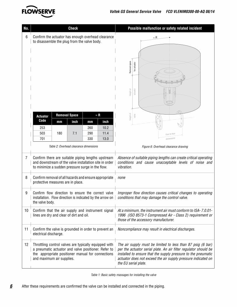
6 Confirm the actuator has enough overhead clearance to disassemble the plug from the valve body.
ActuatorCode
Removal Space ≈ R
mm inch mm inch
253
180 7.1
260 10.2
503 290 11.4
701 330 13.0
Table 2: Overhead clearance dimensions
Heig
ht o
f
val
veFace to face
dimensions
≈ R
Rem
oval
spa
ce
for a
ctua
tor
Heig
ht o
f
actu
ator
Figure 6: Overhead clearance drawing
7 Confirm there are suitable piping lengths upstream and downstream of the valve installation site in order to minimize a sudden pressure surge in the flow.
Absence of suitable piping lengths can create critical operating conditions and cause unacceptable levels of noise and vibration.
8 Confirm removal of all hazards and ensure appropriate protective measures are in place.
none
9 Confirm flow direction to ensure the correct valve installation. Flow direction is indicated by the arrow on the valve body.
Improper flow direction causes critical changes to operating conditions that may damage the control valve.
10 Confirm that the air supply and instrument signal lines are dry and clear of dirt and oil.
At a minimum, the instrument air must conform to ISA- 7.0.01-1996 (ISO 8573-1 Compressed Air - Class 2) requirement or those of the accessory manufacturer.
11 Confirm the valve is grounded in order to prevent an electrical discharge.
Noncompliance may result in electrical discharges.
12 Throttling control valves are typically equipped with a pneumatic actuator and valve positioner. Refer to the appropriate positioner manual for connections and maximum air supplies.
The air supply must be limited to less than 87 psig (6 bar) per the actuator serial plate. An air filter regulator should be installed to ensure that the supply pressure to the pneumatic actuator does not exceed the air supply pressure indicated on the EU serial plate.
Table 1: Basic safety massages for installing the valve
After these requirements are confirmed the valve can be installed and connected in the piping.

Valtek GS General Service Valve FCD VLENIM0300-00-AQ 08/14
7
flowserve.com
1. Remove the protective flange covers and coating from the control valve; clean the flange gasket surface.
NOTICE Unsuitable cleaning agents can dam-age and cause leakage in PTFE and
graphite gaskets. Consult a current chemical resis-tance list before applying.
2. Install the control valve in an upright position whenever possible. Vertical installation permits easier valve maintenance.
3. Install and connect the control valve to the pipeline. Locate gaskets in the center of the body flanges and secure nuts and bolts.
4. Connect the power supply and instrument signal lines.
• For pneumatic actuators, connect the air supply and instrument signal lines.
• For electric actuators, connect the power supply using the wiring diagram located on removable actuator cover or in the manufacturer‘s actuator documentation.
10 Valve Quick-Check
Apply appropriate personal protective equip-ment when working on the control valve to prevent hazards arising from the operation. Protect yourself against freezing, burns and cuts by wearing appropriate protective cloth-ing, gloves and eye protection.
Do not over-tighten packing.
Sudden exposure of the control valve to full working pressure and temperature may cause stress cracks.
Prior to valve operation, we require, that you check the following conditions to reduce the risk of malfunction and safety related incidents.
No. Important information Possible malfunction or safety related incident
1 Avoid critical operating conditions where excessive noise or vibration levels might occur.
Impermissible continuous operation of a control valves under critical conditions can damage the valve.
2 Avoid frequent system start-ups and shutdowns. Critical operating conditions, which can damage the control valve, may be encountered during system start-up or shut down.
3 Keep the operating medium free of foreign particles. Installing a suitable strainer upstream of the control valve can prevent foreign particles from damaging the valve.
4 Instrument air must conform to ISA 7.0.01-1996 (with a dew point at least 18°F (10°C) below ambient temperature, par-ticle size below 1 µm and oil content not to exceed 1 ppm)
Contaminated instrument air can damage the accessories and control valve or cause them to fail.
5 Do not touch the body and bonnet ! The tempera-ture of the operating medium is transferred to the
surface of the control valve.
Excessive hot surface temperatures can put you at risk for burns.
Frigid surface temperatures can put you at risk for freezing.
6 Critical operating conditions can cause exces-sive or hazardous levels of vibration or noise.
Impermissible levels of vibration can cause hearing loss, vascular and nerve damage and damage to joints and bones. Use hearing protection when noise levels exceed 80 dB(A).
7 Incorrect maintenance can result in the emission of hot, cryogenic, and / or toxic operating media.
Incorrect maintenance can put you at risk for heat related burns, freezing, acid burns or poisoning.
Table 3: Basic safety massages for operating the valve

Valtek GS General Service Valve FCD VLENIM0300-00-AQ 08/14
8
4. Continuously increase load until operation parameters are reached.
5. Minor relaxation of the flange bolting is possible after initial assembly. Retorque the bonnet flange bolting if necessary before installation or following an initial temperature excursion to ensure the bonnet gaskets do not leak (See Table 4).
Pressure PN 40 Class 150 Class 300
Size Nm ft lb Nm ft lb Nm ft lb
15 1/2“12,5 9.2 7,3 5.4 9,2 6.820 3/4“
25 1“32 -
26 19.2- - - -
40 1 1/2“ 17 12.5 21 15.550 2“ 19 14.0 22 16.2 27 19.965 -
51 37.6- - - -
80 3“ 26 19.2 43 31.7100 4“ 78 57.5 46 33.9 76 56.0125 - 110 81.1 - - - -150 6“ 140 103.3 76 56.0 146 107.7
Table 4: Recommended Body Bolt Torque Values
Recommended Maintenance Actions
No. Service Inter-val
Valve Condition
Good Adequate Inadequate
1 Visual inspection of the valve
Bi-weekly
No action Clean valve stem with a soft cloth
Overhaul or replace valve after product lifecycle
2 Visual inspection of the packing
Bi-weekly
No action Retighten leaky packing box Replace leaky packing box immedi-ately
Preventive change of the PTFE-packing
Dependent upon results of previous maintenance (see numbers 1 and 2 above) or a minimum of once every 24 months
Preventive change of the Graphite-packing
Dependent upon results of previous maintenance (see numbers 1 and 2 above) or a minimum of once every 18 months
3 Visual inspection ofbody bolting
Yearly No action Retighten body bolting if bonnet gasket leaks.
Remove from service and replace body bolting immediately if gasket leakage persists or if bolting is damaged
4 Visual inspection of the actuator
Bi-weekly
No action Clean actuator stem with a soft cloth
Overhaul or replace actuator after prod-uct lifecycle
Electric gear actuator No action; gear is lubricated for lifetime; overhaul or replace gear / actuator after product lifecycle
11 Valve MaintenanceMaintenance intervals and service life of a valve can only be determined empirically on site. The intervals specified in the User Instructions are recommendations and serve only as a guide. Under problematic operating conditions, maintenance intervals may be significantly reduced. We strongly recom-
mend a site survey followed by establishing a documented procedure for performing the maintenance work. Maintenance personnel should perform and log the work accordingly. The data collected can be used as a basis for dynamically deter-mining the maintenance intervals and activities.
WARNING Due to risk of crushing hazard, do not work between the yoke legs
while the valve is in operation.
Prior to start-up, we strongly recommend that you:
1. Stroke the valve and compare the plug position indicator on the stem clamp to the stroke indicator plate. The plug should change position in a smooth, linear fashion.
NOTICE Graphite packing commonly creates more friction than other materials,
such as PTFE. If over tightened, excessive friction may impair smooth control.
2. Adjust instrument signals to ensure a full stroke.
3. Check the packing box bolting to ensure the correct adjustment (See Section 11: Valve Maintenance).
NOTICE Over tightening can cause excessive packing wear and high stem friction
that may impede plug movement.

Valtek GS General Service Valve FCD VLENIM0300-00-AQ 08/14
9
flowserve.com
No. Service Inter-val
Valve Condition
Good Adequate Inadequate
5 Preventive overhaul of the valve
Dependent upon results of previous maintenance (see numbers 1 to 4 above) or a minimum once every 60 months
6 Operation test No action Perform 3 full strokes if packing and / or bonnet tightening is modified; check for leakage
Recommended maintenance actions using the Logix digital positioner with ValveSight diagnostic solution software7 Visual inspection of
diagnostic interfaceWeekly No action -
valve is healthyTake action per warning Overhaul or replace required part per
alarm8 Check health parameter
of valveWarn-
ingNo action -valve is healthy
Replace packing box compo-nents per warning
Overhaul or replace valve after alarm
9 Check health parameter of actuator
Warn-ing
No action -actuator is healthy
Check and retighten air supply
Overhaul or replace actuator after alarm
10 Check health parameter of control
Warn-ing
No action -control is healthy
Overhaul or replace valve; trim and bonnet components must be checked and / or repaired after alarm
11 Check health parameter of positioner
Warn-ing
No action - positioner is healthy
Start step test Overhaul or replace positioner after alarm
Table 5: Service activities check list
Prior to valve maintenance, we require, that you check the following conditions to reduce the risk of malfunction and safety related incidents.
No. Check Possible malfunction or safety related incident
1 Check the packing follower for proper tightness. The packing follower is spring loaded and factory adjusted. If leakage is detected around the packing follower tighten it clockwise using a wrench in quarter turn intervals until the leakage stops.
Wrench Size Adjustment Interval Maximum AdjustmentSW 24 ~ 15/16 AF
quarter turnone,
three-quarter turnSW 32 ~ 11/4 AFSW 46 ~ 113/16 AF one complete turn
Table 7: Packing Adjustment
Do not overtighten packing.
Overtightened packing can cause excessive packing wear and high stem friction that may impede plug movement.
If leakage cannot be stopped, the packing must be replaced.2 Check for signs of gasket leakage through the bonnet
and end flanges.Tighten the bonnet bolting nuts. See Section 13: Disassembly and Reassembly for instructions. Also see Table 4 in Section 10.
3 Check if all nuts and bolts are securely fastened. Avoid critical operating conditions if excess noise or vibration levels occur during operation.
4 Check valve for smooth, full-stroke operation. Un-steady stem movement could indicate an internal valve problem.
Internal valve failure requires an immediate overhaul or control valve replacement by qualified stuff.
Table 6: Basic safety massages for maintenance the valve

Valtek GS General Service Valve FCD VLENIM0300-00-AQ 08/14
10
After these requirements are confirmed proceed with valve maintenance.
WARNING Crushing hazard ! Failure to keep hands, hair, and clothing away
from all moving parts when operating the control valve can cause serious injury.
1. Clear all dirt and / or foreign material from the plug stem and control valve.
2. If leakage is detected, retighten the packing follower by one full turn clockwise (See Table 7: Packing Adjust-ment).
3. If retightening packing does not stop the leakage, overhaul the control valve and replace the packing (See Section 13: Disassembly and Reassembly).
4. If leakage is detected, retighten bonnet and flange bolting.
5. Make sure all nuts and bolts are securely fastened.
6. If possible, stroke the valve and check for smooth, full-stroke operation. Unsteady stem movement could indicate an internal valve problem.
7. Make sure all accessory brackets and bolting are securely fastened.
8. Check control valve health parameters:
• Characteristic curves of the valve with flow
• Upstream pressure
• Downstream pressure
into the control room.
NOTICE Monitor trim and bonnet compo-nents. If nominal and actual values
differ by more than 5%, an overhaul may be required.
12 Troubleshooting
Contact customer service department or contract partner for any fault or defect found, otherwise the manufacturer‘s guarantee shall be rendered null and void and the manufacturer released from any responsibility. If the user performs the repairs, these User Instructions must be adhered to and carried out in a competent manner. Original Equipment Manufacturer spare parts must be used to make the repair.
Defect No. Possible Causes Remedy
Stem does not move 1.1 • No auxiliary energy supply (pneumatic air or electrical power) to actuator and accessories(positioner, air filter regulator, solenoid valve, limit switch, and/ or special accessories)
• Pneumatic actuators: Check supply for leaks Check air pressure (usually 87 psig; 6 bar)
• Electrical actuators: Check power supply (connections, circuit
breakers, voltage)
1.2 • Mounted accessories do not work • See User Instructions for accessory manufacturer
1.3 • Pneumatic actuator is defective • Contact customer service department or contract partner
1.4 • Electric actuator is defective • See user instructions of the actuator manufacturer
1.5 • Excessive tightening of the pack-ing box
• Loosen packing follower until valve operates properly
NOTICE ! Make sure there are no leaks.
1.6 • Valve trim worn or stuck • Contact customer service department or contract partner
Jerky stem movement 2.1 • Damaged stem • Contact customer service department or contract partner

Valtek GS General Service Valve FCD VLENIM0300-00-AQ 08/14
11
flowserve.com
Defect No. Possible Causes Remedy
Jerky stem movement 2.2 • Electric actuator is defective • Clean stem with suitable cleaning agent
2.3 • Actuator not powerful enough • Compare actuator specifications on the serial plate with operation specifications of the facility. If incompatible, contact customer service department or contract partner
Stem travel less than full stroke(0 to 100 %)
3.1 • Air supply pressure too low • Provide air at the pressure stated on the serial plate (European production only).
3.2 • Pneumatic actuators:Improper handwheel position
• Move handwheel to limit position , otherwise contact factory for information.
3.3 • Electric actuators:Limit switches are out of adjustment
• Readjust limit switch to actuator manufacturer‘s specification
3.4 • Improperly adjusted or defective positioner
• Readjust positioner to positioner manufacturer‘s specification
3.5 • Foreign particles in valve seat or damaged trim
• Contact customer service department or contract partner
Excessive valve seat leakage 4.1 • Damaged sealing surfaces on valve seat or plug
• Contact customer service department or contract partner
4.2 • Foreign particles in seat area • Contact customer service department or contract partner
4.3 • Plug does not close fully • Refer to No. 3.1 to 3.5
Leaking packing box system 5.1 • Compression force on packing box too low
• Slightly retighten packing box
NOTICE ! Make sure stem can still move.
5.2 • Worn packing • Slightly retighten packing box
NOTICE ! Make sure stem can still move.
If the packing does not stop leaking, contact customer service department or contract partner
5.3 • Dirty stem • Clean stem with suitable cleaning agent
5.4 • Damaged stem • Contact customer service department or contract partner
Leaking bonnet gasket 6.1 • Gasket compression is too low • Properly retighten bonnet bolting nuts crosswise
6.2 • Gasket defective • Contact customer service department or contract partner
6.3 • Corrosion • Contact customer service department or contract partner
Leaking body 7.1 • Corrosion or high velocity related damage
• Contact customer service department or contract partner
No limit switch signal 8.1 • Power supply to limit switch interrupted
• Check power supply(connections, circuit breakers, voltage)
8.2 • Limit switch out of adjustment • Readjust limit switch operating distance; see limit switch data sheet
Unstable positioner 9.1 • Defective positioner • See user instruction of the positioner manufacturer
Table 8: Trouble-shooting

Valtek GS General Service Valve FCD VLENIM0300-00-AQ 08/14
12
13 Disassembly and Reassembly
The Valtek GS control valve is allowed to be disassembled and reassembled only by qual-ified staff - personnel who are familiar with disassembling, reassembling, installation and commissioning of this product, and pos-sess the relevant qualifications in their field of activity.
When performing repairs, personnel are to follow these instructions using only original equipment manufacturer (OEM) spare parts and recommended special tools to ensure the reliability of the Valtek GS control valve.
Only Flowserve trained and authorized personnel are allowed to repair (disassemble and reassemble) the Valtek GS in hazard areas.
Valves are provided for oil and grease-less service or oxygen service may only disassembled and reassembled in clean rooms (ISO 14644- ISO 8, US FED STD 209 E - M 6.5, or equivalent).
WARNING Control valves are pressure vessels.Improper opening of the valve or actuator can result in bodily injury.
Prior to disassemble and reassemble, we require, that you check the following conditions to reduce the risk of malfunction and safety related incidents.
No. Important information Possible malfunction or safety related incident
1 Disregarding these instructions may bring serious or harmful consequences.
Failure to comply with these user instructions will render the manufacturer‘s guarantee and liability null and void. Unless otherwise agreed, the manufacturer‘s general terms and conditions of sale shall apply.
2 Always observe system safety instructions when preparing for and performing the repair
procedure.
Potential hazards and their sources are under the operator‘s influence. The operator must observe national and interna-tional environmental regulations for control valve removal from the pipe and cleaning. Permissible exposure limits must be maintained, appropriate personal protective equip-ment must be used and service personnel must be properly instructed in performing the repair procedure.
3 Make sure the pipeline is depressurized an in ambient state, also a suitable rigging (e.g.
Endless Sling) and securing devices (e.g. Vee Trough with Stands / Vise) are readily available.
Remove the Valtek GS from the pipeline in a depressur-ized and ambient state. Failure to do so can cause serious personal injury.The control valve is not equipped with integral stands, therefore guard against the valve from tipping over. Bodily injuries can be the result. Use appropriate clamps, block-ing or other stabilizing support. Attachment to overhead crane can ensure stability.
4 Confirm that you have the required spare parts at the site. Not having the full complement of parts, accessories and tools can slow or stop repair work.
5 Confirm that you have the required tools avail-able to manage the disassembly and reassembly
(See Section 16: Special Tools).
Improper tools and / or improper use of tools can result in personal injury or damage to the parts.
6 Review the serial plate information to identify the valve. The serial number and the part numbers needed are re-quired when ordering spare parts.
A serial plate used for product identification is attached on every control valve (See Section 3: Product Identifica-tion).
7 Do not damage any valve surfaces during repair. Damaging the stem surface and / or packing area may lead to premature leakages in the packing area.
8 Check all parts for damage such as scoring, deformities, corrosion or overexpansion.
If in doubt, replace faulty parts.Never reuse gaskets.
Table 9: Basic safety massages for repairing the control valve

Valtek GS General Service Valve FCD VLENIM0300-00-AQ 08/14
13
flowserve.com
After these requirements are confirmed the control valve can be maintained and repaired.
Description of the Procedure1. Disconnect the air supply from the actuator and / or
assembled accessories.
2. Disassemble the positioner from the valve as neces-sary (See Figure 7: Remove the positioner).
3. Move the actuator to the open (retracted) position.
4. Turn the lock nut (113) clockwise to loosen. Keep up-per coupling (249) from turning by securing with a wrench (See Figure 8: Remove the actuator).
5. Turn the cap screws (240) counter clockwise to loosen.
6. Turn the yoke lock nut (76) counter clockwise to loosen.
7. Lift off and store the actuator safely. 8. Place the valve body assembly on a table for disas-
sembly.
Disassembly instructions of the valve body assembly (standard or extended bonnet design).
1. Turn the bonnet nuts (114) counter clockwise to loosen
(See Figure 9: Disassemble / Reassemble the valve). 2. Turn the packing follower (80) counter clockwise to
loosen. 3. Remove the Belleville springs (109). 4. Remove the upper stem guide (87). 5. Place the Ring Nut Tool (See Section 16: Special Tools)
on the stem (50) and turn slowly.
WARNING Crushing hazard ! Lifting the bonnet and plug from
the control valve involves personal physical risk by falling parts.
Please exercise caution.
NOTICE Exercise care with a pressure bal-anced plug design. While removing
the pressure balanced plug the cage may stick to the plug head then become detached while lifting the plug and stem out of the valve. Secure the cage as you re-move the plug and stem.
O-ring
Positioner
Socket screw
Figure 7: Remove the positioner
240
345
76
113
249
Figure 8: Remove the actuator
ItemPart
ItemPart
WW 1) EU 2) WW EU
76 5.10 Yoke lock nut 249 5.3 Upper coupling113 5.2 Lock nut 345 5.1 Lower coupling240 5.5 Cap screw Table 10: Coupling parts identification
1) WorldWide 2) European Union

Valtek GS General Service Valve FCD VLENIM0300-00-AQ 08/14
14
6. Remove the bonnet gasket (58). 7. Insert the Seat Change Tool (See Section 16: Special
Tools) into the body of the valve until the pin clicks into place. Use a suitable torque wrench to remove the seat ring.
8. Remove the seat ring (20) and profile ring (55). 9. Remove the plug (50) from the bonnet (40).
10. Use the Packing Driver Tool (See Section 16: Special Tools) to remove the packing (88) and the packing box ring (93).
11. Use a standard brass scraper or other suitable tool to remove all old gasket material; then clean the gasket surfaces.
NOTICE Examine the valve trim and bon-net components. If the nominal and
actual values differ by more than 5% a control valve overhaul may be required (See Point 8, Page 9).
12. Check stressed surface areas for damage such as scoring and deformities.
13. Use a standard brass scraper or other suitable tool to
clean bolting. Check for corrosion or any other damage.
Reassembly instructions of the valve body assembly (standard or extended bonnet design).
14. Lubricate all bolt and screw threads and bearing sur-faces (stem, underside of the nuts) with a suitable, ap-proved lubricant (See Section 15: Lubricants).
NOTICE Never allow lubricants to come in contact with the bonnet or sealing surfaces.
15. Install and finger tighten a new profile ring (55) and seat ring (20).
16. Insert the Seat Change Tool (See Section 16: Special Tools) into the body of the valve and turn clockwise using a suitable torque wrench (See Section 14: Required Torque, for screwed seat rings).
17. Lower the plug (50) into the body and place it into the seat ring (See page 18 for pressure balanced and MultiStream trim).
18. Install the new bonnet gasket (58).
19. Carefully lower the bonnet (40) onto the plug in the
1
108
55
20
58
50
40
114
93
88
87
109
80
Figure 9: Disassemble / Reassemble the valve
Item Part Item Part
1 Body 87 Upper stem guide20 Seat ring 88 Packing40 Bonnet 93 Packing box ring50 Plug 108 Stud bolt55 Bonnet gasket 109 Belleville spring58 Bonnet gasket 114 Hex nut80 Packing follower Table 11: Valve parts

Valtek GS General Service Valve FCD VLENIM0300-00-AQ 08/14
15
flowserve.com
body of the valve.
20. Install and finger tighten the bonnet nuts (114) to the bonnet bolts (108).
21. Install the packing box ring (93) and the new packing (88).
NOTICE Install and push two packing rings consecutively using the Tamping
Tool and pre-tighten it using the Compression Tool. Repeat the procedure with remaining rings. Rotate each ring 180° from the overlapping point. Make sure each ring is clean. Dirty rings result in stem leakage.
(See Table 18, Page 23)
22. Install the upper stem guide (87), Belleville springs (109), and the packing follower (80). Tighten the pack-ing follower with your fingers clockwise until resis-tance can be felt.
NOTICE The belleville springs (109) must be stacked in series.
23. Tighten the bonnet nuts (114) in four steps - 30%, 60%, 100%, and all around 100% - using a crosswise pattern (See Section 14: Torque Requirements).
NOTICE Check the plug’s freedom of movement by lifting it approximately ~10 mm (0.4
inch) between tightenings. Loosen the bolted connection and start again if it proves difficult to move the plug.
24. Finish packing follower tightening with a wrench (See Table 7, Page 9).
NOTICE Do not over tighten the packing. Over tightened packing may produce
higher friction and reduce product service life.
25. Replace the pneumatic diaphragm or multi-turn actua-tor and accessories (See page 19).
26. After reinstalling the control valve in the pipeline, perform 3 full strokes and check the tightening of the packing follower and bonnet bolting.
27. Log the maintenance interval and the work performed.
Disassembly of the valve with a Bellows Seal Bonnet Assembly.
1. Turn the bonnet nuts (114) counter clockwise to loosen(See Figure 10: Disassemble / Reassemble the valve with bellows seal bonnet type A).
2. Turn the packing follower (80) counter clockwise to loosen.
3. Remove the Belleville springs (109).
4. Remove the upper stem guide (87).
5. Place the Ring Nut Tool (See Section 16: Special Tools) on the stem (50) and turn slowly.
WARNING Crushing hazard ! Lifting the bonnet and plug from
the control valve involves personal physical risk by falling parts.
Please exercise caution.
NOTICE Exercise care with a pressure bal-anced plug design. While removing
the pressure balanced plug the cage may stick to the plug head then become detached while lifting the plug and stem out of the valve. Secure the cage as you re-move the plug and stem.
6. Remove the bonnet gasket (58).
7. Insert the Seat Change Tool (See Section 16: Special Tools) into the body of the valve until the pin clicks into place. Use a suitable torque wrench to remove the seat ring.
8. Remove the seat ring (20) and profile ring (55).
9. Turn the bonnet nuts (110) counter clockwise to loosen.
10. Remove the head (7) and upper bonnet gasket (59).
NOTICE There are two different bellows seal designs.
Type Size Twist lock betweenplug and stem
Connection between bellows and bonnet
A 15 - 50 1/2“ - 2“ Lock bushing ClampedB 65 - 150 3“ - 6“ Lock pushing Screwed
Table 12: Bellows seal bonnet types
11. Disassembling each type of Bellows Seal Assembly:
Type A Bellows Seal Assembly:
Lower the plug (50) into a three jaw-chuck with soft brackets and turn the plug from the stem and bonnet (6 / 40) counter clockwise to loosen then move the bellows seal assembly up and out.
Type B Bellows Seal Assembly:

Valtek GS General Service Valve FCD VLENIM0300-00-AQ 08/14
16
Turn the hex nut (113) from the bellows seal assembly (6) counter clockwise to loosen, remove the seal car-rier (91) and profile ring (60) then move the bellows seal assembly down and out.
NOTICE The bolting between plug and stem are secured against twisting. Type A
and B bellows seal assemblies are secured with a lock bushing (8).
12. Use the Packing Driver Tool (See Section 16: Special Tools) to remove the packing (88) and the packing box ring (93).
13. Use a standard brass scraper or other suitable tool to remove all old gasket material; then clean the gasket surfaces.
NOTICE Examine the valve trim and bon-net components. If the nominal and
actual values differ by more than 5% a control valve overhaul may be required.
14. Check stressed surface areas for damage such as scoring or deformities.
15. Use a standard brass scraper or other suitable tool to clean all bolting. Check for corrosion or any other damage.
Reassembly of the valve with a Bellows Seal Bonnet Assembly:
16. Lubricate all bolt and screw threads and bearing sur-faces (stem, plug, underside of the nuts) with a suit-able, approved lubricant (See Section 15: Lubricants).
NOTICE Never allow lubricants to come in contact with the bonnet or sealing
surfaces.
17. Install and finger tighten a new profile ring (55) and seat ring (20).
18. Insert the Seat Change Tool (See Section 16: Special Tools) into the body of the valve and turn clockwise using a suitable torque wrench (See Section 14: Re-quired Torque, for screwed seats).
19. Lower the plug (50) into a three jaw-chuck with soft brackets and install a new lock bushing (8) into the plug (Type A and B).
NOTICE The cone of the lock bushing must open to the top.
1
108
55
58
20
50
8
40
114
106
59
6
59
42
48
110
7
93
88
87
109
80
Figure 10: Disassemble / Reassemble the valve with bellows seal assembly for type A designs (Valve parts see Table 13, Page 17)

Valtek GS General Service Valve FCD VLENIM0300-00-AQ 08/14
17
flowserve.com
Reassembling Type A bellows:
Carefully lower the bonnet (40) onto the plug. Install a new head gasket (59) and insert the bellows seal assembly (6) from the top of the bonnet (40). Finger tighten the stem (6) clockwise onto the plug (50). Tighten the stem (6) using a suitable torque wrench.
Reassembling Type B bellows:
Install the bellows seal assembly (6) clockwise onto the plug (50). Tighten the stem (6) using a suitable torque wrench.
Insert the bellows seal assembly (6) type B through the underside of the bonnet (40), install a new profile ring (60) and seal carrier (91) on top. Turn hex nut (60) clockwise and finger tighten.(See Section 14: Required Torques, for plug and stem)
20. Install the new bonnet gasket (58).
21. Carefully lower the pre-assembled bonnet in the body of the valve (See page 18 for pressure balanced and MultiStream trim).
22. Install and finger tighten the bonnet nuts (114) to the bonnet bolts (108).
23. Install the new flat gasket (59).
24. Carefully lower the head (7) onto the stem and bonnet.
25. Install and finger tighten the nuts (110) to the studs (106).
26. Install the packing box ring (93) and the new packing (88).
NOTICE Install and push two packing rings consecutively using the Tamping
Tool and pre-tighten it using the Compression Tool. Repeat the procedure with remaining rings. Rotate each ring 180° from the overlapping point. Make sure each ring is clean. Dirty rings result in stem leakage.
(See Table 18, Page 23)
27. Install the upper stem guide (87), Belleville springs (109), and the packing follower (80). Tighten the packing follower with your fingers clockwise until resistance can be felt.
NOTICE The Belleville springs (109) must be stacked in series.
28. Tighten the bonnet nuts (114) in four steps - 30%, 60%, 100%, and all around 100% - using a crosswise pattern (See Section 14: Torque Requirements).
8
50
6
40
60
91
113
106
Figure 11: Disassemble / Reassemble the valve with bellows seal assembly for type B design
Item Part Item Part Item Part1 Body 50 Plug 91 Seal carrier6 Stem 55 Profile ring 93 Packing box ring7 Head 58 Bonnet gasket 106 Stud bolt8 Lock bushing 59 Head gasket 108 Stud bolt20 Seat ring 60 Profile ring 109 Belleville spring40 Bonnet 80 Packing follower 110 Hex nut42 Plug screw 87 Upper stem guide 113 Hex nut48 Plug gasket 88 Packing 114 Hex nut
Table 13: Valve parts with bellows seal

Valtek GS General Service Valve FCD VLENIM0300-00-AQ 08/14
18
29. Tighten the nuts (110) in four steps - 30%, 60%, 100%, and all around 100% - using a crosswise pattern (See Section 14: Torque Requirements).
NOTICE Check the plug’s freedom of movement by pushing / lifting it approximately
~10 mm (0.4 inch) between tightenings. Loosen the bolted connection and start again if it proves difficult to move the plug.
30. Finish packing follower tightening with a wrench (See Table 7, Page 9).
NOTICE Do not over tighten the packing. Over tightened packing may produce
higher friction and reduce product service life.
31. Replace the pneumatic diaphragm or multi-turn actua-tor and accessories (See page 19).
32. After reinstalling the control valve in the pipeline, perform 3 full strokes and check the tightening of the packing follower and bonnet bolting.
33. Log the maintenance interval and the work performed.
Extended plug version with MultiStream noise reduction trim:
1. Lower the multiple orifice cylinder (30) and spring (133) into the body and place it onto the seat.
2. Lower the plug (50) into the body and place it into the seat.
3. Continue with the standard prozedure in the corre-sponding chapter.
133
30
Figure 12: Extended bonnet trim for MultiStream
Item Part Item Part
30 Multiple orifice cylinder 133 Spring
Table 14: Valve parts extended bonnet trim with MultiStream
Extended bonnet version with a pressure balanced or MultiStream trim:
1. Reassembling for the pressure balanced V-ring, a new driving band (66) and a new sealing ring (65).
Reassembling for the pressure balanced Piston-ring, two new sealing rings (65).
NOTICE Install rings consecutively.
2. Lower the multiple orifice cylinder (30) and cage (31) into the body and place it onto the seat.
3. Install the new cage gasket (56).
4. Lower the plug (50) into the body and place it into the seat.
5. Continue with the standard prozedure in the corre-sponding chapter.
30
50
65
65 66*
56
31
Figure 13: Extended bonnet trim for pressure balanced designs
Item Part Item Part
30 Multiple orifice cylinder 56 Cage gasket31 Cage 65 Sealing ring50 Plug 66 Driving band
Table 14: Valve parts extended bonnet trim equipment - balancing and MultiStream
* Type V-ring pressure balanced design with one driving band (65) and one sealing ring (66).
Type Piston-ring pressure balanced design with two sealing rings (65).

Valtek GS General Service Valve FCD VLENIM0300-00-AQ 08/14
19
flowserve.com
O-ring
Positioner
Socket screw
Figure 14: Remove the positioner
240
345
76
113
249
Figure 15: Remove the actuator
ItemPart
ItemPart
WW 1) EU 2) WW EU
76 5.10 Yoke lock nut 249 5.3 Upper coupling113 5.2 Lock nut 345 5.1 Lower coupling240 5.5 Cap screw Table 16: Coupling parts identification
1) WorldWide 2) European Union
Reassemble the actuator and positioner onto the valve:
1. Mount the pneumatic diaphragm or multi-turn actuator onto the bonnet and tighten the yoke lock nut (76) clockwise (See Section 14: Required Torques).
NOTICE The legs of the yoke should be parallel to the flow direction.
2. Move the actuator to the open position.
3. Screw in the lower coupling (345) three turns and move the actuator into the closed position.
NOTICE The plug must be aligned onto the seat. The cushioning effect of the bel-
lows can be prevented by tightening the packing follower.
4. Move the actuator back into the open position and adjust the distance between the lower coupling (345) and upper coupling (249) by adjusting the stroke length.
Size Stroke
15 - 50 1/2“ - 2“ 20 + 0,5 mm 0.787 + 0.02 in.
65 - 100 3“ - 4“ 40 + 0,5 mm 1.574 + 0.02 in.
125 - 150 6“ 60 + 0,8 mm 2.362 + 0.03 in.
Table 15: Stroke adjustment length
5. Move the actuator to the close position and install the cap screws (240).
6. Lock the lock nut (113). Keep upper coupling (249) from turning by securing with a wrench.
7. Reassemble the positioner on the valve as necessary (See relevant accessory User Instruction).
8. Connect the valve into the pipeline (See Section 9: Installation).
9. After reinstalling the control valve into the pipeline, perform three full strokes and check the tightness of the packing follower and bonnet bolting (See Section 10: Valve Quick-Check).
10. Log the maintenance interval and the work performed.

Valtek GS General Service Valve FCD VLENIM0300-00-AQ 08/14
20
14 Torque RequirementsValtek GSPresssure
Class
Torque Requirements for BONNET NUTs (58) per nominal diameter
15 20 25 32 40 50 65 80 100 125 1501/2“ 3/4“ 1“ - 1 1/2“ 2“ - 3“ 4“ - 6“
PN 16 / 40Nm
12,5 26 19 51 78 110 140Class 150 7,3
-17 22
-26 46
-76
Class 300 9,2 21 27 43 76 146PN 16 / 40
ft lb9.2 19.2 14.0 38 58 81 103
Class 150 5.4-
12.5 16.2-
19.2 34-
56Class 300 6.8 15.5 19.9 32 56 108
Valtek GSPresssure
Class
Torque Requirements for SEAT RINGs (20) per nominal diameter
15 20 25 32 40 50 65 80 100 125 1501/2“ 3/4“ 1“ - 1 1/2“ 2“ - 3“ 4“ - 6“
PN 16 / 40Nm 40 100 162 457 841 1046 1653
Class 150 / 300PN 16 / 40
ft lb 30 74 120 337 620 772 1219Class 150 / 300
Valtek GSPresssure
Class
Torque Requirements for HEAD NUTs (110) per nominal diameter
15 20 25 32 40 50 65 80 100 125 1501/2“ 3/4“ 1“ - 1 1/2“ 2“ - 3“ 4“ - 6“
PN 16 / 40Nm
1322 44
Class 150-
14-
30-
24Class 300 10 12 25 46PN 16 / 40
ft lb9.6
16.2Class 150
-10.3
-22
-17.7
Class 300 7.4 8.9 18.4 34
Valtek GSPresssure
Class
Torque Requirements for PLUG and STEM (50, 6) per nominal diameter
15 20 25 32 40 50 65 80 100 125 1501/2“ 3/4“ 1“ - 1 1/2“ 2“ - 3“ 4“ - 6“
PN 16 / 40Nm 40 80 170
Class 150 / 300PN 16 / 40
ft lb 30 59 125Class 150 / 300
15 Lubricants
UseLubricant / Antiseize
WW (World Wide) EU (European Union)
Standard,from -40°F to +752°F -40°C to +400°C
Threads of the Seat-Ring (20, 1), Stem (6, 50) and Bonnet-BoltingFastorq A/G
Klüber HEL 46-450Guide of the Plug (50), V-Ring / Piston-Ring Balancing (65) and Twist-Lock of the Stem (6)Threads of the Packing-Follower (80), Coupling (113, 345, 249, 240) and Yoke Locknut (76) Klüberpaste 46 MR 401Actuator O-Ring‘s (272, 271, 275, 278) DOW Molykote 55 O-Ring Klüber Unisilikon L 250 LThreads of the Actuator Casing-Bolting (211, 335, 336) and Guide (254) Fastorq A/G Klüberpaste 46 MR 401
Low temperature,from -76°F to -40°F -60°C to -41°C
Threads of the Seat-Ring (20, 1), Stem (6, 50) and Bonnet-BoltingAlcohol 96%Guide of the Plug (50), V-Ring Balancing (65) and Twist-Lock of the Stem (6)
Threads of the Packing-Follower (80), Coupling (113, 345, 249, 240) and Yoke Locknut (76)Actuator O-Ring‘s (272, 271, 275, 278) DOW Molykote 55 O-Ring Klüber Unisilikon L 250 LThreads of the Actuator Casing-Bolting (211, 335, 336) and Guide (254) Fastorq A/G Klüberpaste 46 MR 401
Oxygen,from -40°F to +320°F -40°C to +160°C
Threads of the Seat-Ring (20, 1), Stem (6, 50) and Bonnet-BoltingDuPont Krytox GPL 206 Klüberalfa YV 93-1202Guide of the Plug (50), V-Ring Balancing (65) and Twist-Lock of the Stem (6)
Threads of the Packing-Follower (80), Coupling (113, 345, 249, 240) and Yoke Locknut (76)Actuator O-Ring‘s (272, 271, 275, 278) DOW Molykote 55 O-Ring Klüber Unisilikon L 250 LThreads of the Actuator Casing-Bolting (211, 335, 336) and Guide (254) Fastorq A/G Klüberpaste 46 MR 401

Valtek GS General Service Valve FCD VLENIM0300-00-AQ 08/14
21
flowserve.com
16 Special ToolsSpecial Tool Use
Seat Change Tool
Recommended tool for disassembling and reassembling.
Part N° See spare parts catalog
Torque wrench cannot afford such needed high torques. Use therefore an mechanical force multiplier - for example JUWEL Type 01 RS or Type 03L or equivalent.
PackingCentering
Tool
PackingTampingTool
Packing Tamping Tool
Recommended tool for assembling.
Part N° See spare parts catalog
PCTSleeveLong
PCTSleeveShort
PackingCompression Tool
Packing Compression Tool
Recommended tool for assembling.
Part N° See spare parts catalog
Ring Nut Tool
Recommended tool for disassembling and reassembling.
Part N° See spare parts catalog
Packing Driver Tool
Recommended tool for disassembling.
Part N° See spare parts catalog
Stem Tightening Tool
Recommended tool for disassembling and reassembling.
Part N° See spare parts catalog
Alternatively, one can use also an automatic stud driver.

Valtek GS General Service Valve FCD VLENIM0300-00-AQ 08/14
22
1
108
55
20
58
8
50
80
109
87
88
93
7
110
48
42
59
106
59
6
114
40
Figure 16: Complete valve parts
17 Parts List 1) see page 17, 2) and 3) see page 18
ItemPart Available Materials
Spar
e Pa
rts
WW1) EU2)
1 1.1 Body 1.0619 A216 WCC 1.4408 A351 CF8M
6 2.4 Bellows seal Unit 316 SS
7 3.15 Head 1.0460or
1.0619
A105or
A216 WCC
1.4404or
1.4408
316 Lor
A351 CF8M
8 2.3 Lock Bushing 316 SS
20 2.1 Seat Ring 316 SS S
30 2.26 Multi. Cylinder 3) 1.4571 K
31 2.9 Cage 2) A351 CF8M
40 3.1 Standard BonnetExtension BonnetBellows Seal Bonnet
1.0460or
1.0619
A105or
A216 WCC
1.4404or
1.4408
316 Lor
A351 CF8M
42 3.14 Plug Screw A2
48 3.13 Gasket Pure Graphite D
50 2.2 Contoured Plug316 SS (Alloy 6) K
Quick Open
55 2.5 Profile Ring Pure Graphite S
56 2.10 Cage Gasket 2) Pure Graphite
58 1.2 Bonnet Gasket Pure Graphite on Support Plate from 1.4401
D59 2.15 Head Gasket Pure Graphite
60 2.8 Profile Ring 1) Pure Graphite
65 2.12 Sealing Ring 2) PTFE-Rings
66 2.21 Driving Band 2) PTFE
80 3.4 Packing Follower 316 SS
83 3.1.1 Lower Stem Guide 316 SS (nitrided)
87 3.6 Upper Stem Guide 316 SS
88 3.3 Packing PTFE-RingsD
Graphite-Rings
91 2.7 Seal Carrier 1) 316 SS
93 3.2 Packing box ring 316 SS
106 3.17 Stud Bolt KG A193 A2-70 A193
108 1.3 Stud Bolt KG A193 A2-70 A193
109 3.7 Belleville Spring 1.4310
110 3.16 Hex Nut KG A194 A2-70 A194
113 2.6 Hex Nut 1) 316 SS
114 1.4 Hex Nut KG A194 A2-70 A194
133 2.28 Spring 3) 1.4568
1) WorldWide 2) European Union K = Plug Kit, S = Seat Kit, D = Gasket Kit

Valtek GS General Service Valve FCD VLENIM0300-00-AQ 08/14
23
flowserve.com
18 DisposalUp to 95 % of the Valtek GS control valve is metal. The re-maining materials are synthetic, rubber, polytetrafluoroethyl-ene (PTFE), graphite, paint, and lubricants.
NOTICE Potential hazards and their sources are un-der the operator‘s influence. The operator
must observe national and international environmental condi-tions for control valve removal from the pipeline and cleaning. Permissible limit values must be maintained to ensure suit-able protective measures; service personnel must be prop-erly instructed in performing the disassembly and reassembly procedure.
The valve should be professionally disassembled and reas-sembled. Metal parts should be scrapped, with the remaining materials disposed of according the national conditions.
Peripheral units (accessories) should be recycled according the relevant manufacturer‘s User Instructions.
Parts List - Packing DetailsPart Detail
PTFE Packing (88)
This consists of:
1 Pc. Anti Extrusion Ring
4 Pcs. Packing Rings
1 Pc. Anti Extrusion Ring
Rotate each ring 180° from the overlapping point.
Graphite Packing (88)
This consists of:
5 Pcs. Packing Rings
Rotate each ring 180° from the overlapping point.
Belleville Springs (109)
The two Belleville springs must stacked in series !
Table 17: Packing Details

USAFlowserve Flow Control Division 1350 N. Mt. Springs ParkwaySpringville, UT 84663USAPhone: +1 801 489 8611Fax: +1 801 489 3719
AustriaFlowserve Control Valves GmbH Kasernengasse 69500 VillachAUSTRIAPhone: +43 (0) 4242 41181 - 0Fax: +43 (0) 4242 41181 - 50
FranceFlowserve France S.A.SPB 60 63307 Thiers CedexFRANCEPhone: +33 4738 04266Fax: +33 4738 01424
IndiaFlowserve India Controls Pvt Ltd. Plot # 4, 1A, Road #8 EPIP White-field Bangalore, Karnataka, 560066INDIAPhone: 91 80 40146200Fax: 91 80 28410286
ChinaFlowserve Fluid Motion andControl (Suzhou) Co., Ltd.No. 35, Baiyu Road,Suzhou Industrial Park,Suzhou Jiangsu Province,P.R. 215021 CHINAPhone: 86 512 6288 8790Fax: 86 512 6288 8736
SingaporeFlowserve Pte. Ltd.12 Tuas Avenue 20Republic of Singapore 638824SINGAPOREPhone: +65 6879 8900Fax: +65 6862 4940
Saudi ArabiaFlowserve Abahsain Flow Control Co., Ltd.Makkah Road, Phase 4Plot 10 & 12, 2nd Industrial CityDamman, Kingdom of Saudi ArabiaPhone: +966 3 857 3150 X 243Fax: +966 3 857 4243
To find your local Flowserve representativeor for more information about Flowserve Corporation, visitwww.flowserve.com.
FCD VLENIM0300-00-AQ Printed in USA. August 2014
Flowserve Corporation has established industry leadership in the design and manufacture of its products. When properly selected, this Flowserve product is designed to perform its intended function safely during its useful life. However, the purchaser or user of Flowserve products should be aware that Flowserve products might be used in numerous applications under a wide variety of industrial service conditions. Although Flowserve can (and often does) provide general guidelines, it cannot provide specific data and warnings for all possible applications. The purchaser/user must therefore assume the ultimate responsibility for the proper sizing and selection, installation, operation, and maintenance of Flowserve products. The purchaser/user should read and understand the Installation Operation Maintenance (IOM) instructions included with the product, and train its employees and contractors in the safe use of Flowserve products in connection with the specific application.
While the information and specifications contained in this literature are believed to be accurate, they are supplied for informative purposes only and should not be considered certified or as a guarantee of satisfactory results by reliance thereon. Nothing contained herein is to be construed as a warranty or guarantee, express or implied, regarding any matter with respect to this product. Because Flowserve is continually improving and upgrading its product design, the specifications, dimensions and information contained herein are subject to change without notice. Should any question arise concerning these provisions, the purchaser/user should contact Flowserve Corporation at any one of its worldwide operations or offices.
© 2014 Flowserve Corporation, Irving, Texas, USA. Flowserve is a registered trademark of Flowserve Corporation.