use of geocomposite drainage systems as a temporary
TRANSCRIPT

!•!
Technical Report REMR-GT-24 October 1996
US Army Corps of Engineers Waterways Experiment Station
Repair, Evaluation, Maintenance, and Rehabilitation Research Program
Use of Geocomposite Drainage Systems as a Temporary Measure to Improve the Surficial Stability of Levees
by Dov Leshchinsky, Leshchinsky, Inc.
Approved For Public Release; Distribution Is Unlimited
-;^r^T^^^!RV,;l,,,,
rlfljcQ0Al35^^öt'^1^ "
19961231 003 Prepared for Headquarters, U.S. Army Corps of Engineers

The following two letters used as part of the number designating technical reports of research published under the Repair, Evaluation, Maintenance, and Rehabilitation (REMR) Research Program identify the problem area under which the report was prepared:
Problem Area Problem Area
CS Concrete and Steel Structures EM Electrical and Mechanical GT Geotechnical El Environmental Impacts HY Hydraulics OM Operations Management CO Coastal
The contents of this report are not to be used for advertising, publication, or promotional purposes. Citation of trade names does not constitute an official endorsement or approval of the use of such commercial products.
£if HUNTED ON RECYCLED PAPER

Repair, Evaluation, Maintenance, and Technical Report REMR-GT-24 Rehabilitation Research Program October 1996
Use of Geocomposite Drainage Systems as a Temporary Measure to Improve the Surficial Stability of Levees by Dov Leshchinsky
Leshchinsky, Inc. Newark, DE 19711
Final report Approved for public release; distribution is unlimited
Prepared tor U.S. Army Corps of Engineers Washington, DC 20314-1000
Under Contract No. DACW39-94-C-0073, Work Unit 32646
Monitored by U.S. Army Engineer Waterways Experiment Station 3909 Halls Ferry Road, Vicksburg, MS 39180-6199

US Army Corps of Engineers Waterways Experiment Station
HEADCUMiraS BULDHG
POft NPOMATON OCKMCT:
PUBLIC AFFAIRS OFFICE
U.S. ARMY ENGINEER WATERWAYS EXPEHUBd STATION SOS HALLS FERRY ROAD
VCKSSURO, WSSBSPPI »1»M1W PHONE: (B01)B34-2S0J
OP MBBWATON - V m»■■
Waterways Experiment Station Cataloging-in-Publication Data
Leshchinsky, Dov. Use of geocomposite drainage systems as a temporary measure to
improve the surficial stability of levees / by Dov Leshchinsky ; prepared for U.S. Army Corps of Engineers ; monitored by U.S. Army Engineer Waterways Experiment Station..
42 p.: ill.; 28 cm. — (Technical report; REMR-GT-24) Includes bibliographic references. 1. Levees — Stability. 2. Slopes (Soil mechanics) — Stability.
3. Drainage. 4. Embankments — Stability. I. United States. Army. Corps of Engineers. II. U.S. Army Engineer Waterways Experiment Station. III. Repair, Evaluation, Maintenance, and Rehabilitation Research Program. IV. Title. V. Series: Technical report (U.S. Army Engineer Waterways Experiment Station); REMR-GT-24. TA7 W34 no.REMR-GT-24

Contents
Preface v
Conversion Factors, Non-SI to SI Units of Measurement vi
1—Introduction 1
2—Geocomposite Drainage Systems 3
Background 3 Applications 8
3—Geocomposite Drainage Systems in Levees 19
Purpose 19 Application 19 Design 20 Construction 28
4—Conclusion 32
References 34
Tables 1-3
SF298
List of Figures
Figure 1. Typical geocomposite drainage systems (after Murray and McGown 1992) 4
Figure 2. Illustrations of thick and thin drainage cores (after Murray (and McGown 1992) 6
Figure 3. Idealized deformation of geocomposite drain (after Kraemer and Smith 1986) 6
Figure 4. Flow capabilities of geocomposite drains (after Murray and McGown 1992) 7
Figure 5. Applications of geocomposite drains (after Murray and McGown 1992) 9
in

Figure 6. Plans for installation of curtain drains near Durango, CO (after Hunt 1993) 10
Figure 7. Water table after installation of curtain drains near Durango, CO (after Hunt 1993) U
Figure 8. Standard plans for subsurface drains, Colorado Department of Transportation (after Hunt 1993) 13
Figure 9. Compressibility behavior of selected geocomposite sheet drain systems (courtesy of Prentice-Hall, Koerner 1994) . . 15
Figure 10. Flow rate behavior of selected geocomposite sheet drain systems (courtesy of Prentice-Hall, Koerner 1994) 17
Figure 11. Design guide for geocomposite drains (courtesy of Prentice-Hall, Koerner 1994) 18
Figure 12. Schematic view of geocomposite drain installed as an interceptor in a levee 20
Figure 13. Plan view of levee: presumptive layout of composite drains 21
Figure 14. Section A-A (from Figure 13) along installed geocomposite drain 23
Figure 15. Section B-B (from Figure 13) perpendicular to drainage trench 24
Figure 16. Various configurations of corrugated tubing drainage system (courtesy of Multi-Flow Drainage Systems) 25
Figure 17. Prefabricated couplings and outlets (courtesy of Multi- Flow Drainage Systems) 26
Figure 18. Flow rates for the corrugated tubing drainage system (courtesy of Multi-Flow Drainage Systems) 27
Figure 19. Detail showing transition from installed geocomposite drainage systems to a drainage ditch at toe 29
Figure 20. Construction scheme 30
IV

Preface
The work described in this report was authorized by Headquarters, U.S. Army Corps of Engineers (HQUSACE), as part of the Geotechnical Problem Area of the Repair, Evaluation, Maintenance, and Rehabilitation (REMR) Research Program. The work was performed under Civil Works Unit 32646, "Levee Rehabilitation." The REMR Technical Monitor was Mr. Arthur H. Walz (CECW-EG).
Mr. David Mathis (CERD-C) was the REMR Coordinator at the Director- ate of Research and Development, HQUSACE. Mr. James E. Crews (CECW-O) and Dr. Tony C. Liu (CECW-EG) served as the REMR Overview Committee. The REMR Program Manager was Mr. William F. McCleese, U.S. Army Engineer Waterways Experiment Station (WES). Mr. W. Milton Myers, Geotechnical Laboratory (GL), WES, was the Problem Area Leader.
The study was performed by Dr. Dov Leshchinsky, Leshchinsky, Inc., under Contract No. DACW-94-C-0073 to WES. Dr. Edward B. Perry, Soil and Rock Mechanics Division (S&RMD), Geotechnical Laboratory (GL), was Principal Investigator. The work was conducted under the general supervision of Dr. Don C. Banks, Chief, S&RMD, and Dr. William F. Marcuson III, Director, GL.
Director of WES during the conduct of this study and preparation of the report was Dr. Robert W. Whalin. The Commander was COL Bruce K. Howard, EN.
The contents of this report are not to be used far advertising, publication, or promotional purposes. Gtation of trade names does not constitute an official endorsement or approval of the use of such commercial products.

Conversion Factors, Non-SI to SI Units of Measurement
Non-SI units of measurement used in this report can be converted to SI units as follows:
Multiply By To Obtain
feet 0.3048 meters
inches 2.54 centimeters
pounds (force) 4.448222 newtons
pounds (force) per foot 14.593904 newtons per meter
pounds (force) per square inch 6.8947579 kilopascals
pounds (force) per square foot 0.04788 kilopascals
pounds (mass) per cubic foot 0.1570873 kilonewtons per cubic meter
gallons 3.785412 liters
VI

1 Introduction
Some levees are constructed of clayey soils. Their side slopes are gentle enough to produce a structure having a prescribed margin of safety against rotational failure. However, during dry periods, the clay near the surface shrinks, and subsequently, cracks are formed. The tendency of these desic- cation cracks to develop increases with increase in the plasticity index of the clay. The cracks may be open to a depth of 5 to 7 ft (Fleming, Sills, and Stewart 1994). These cracks expose the interior of the mass allowing deeper desiccation to occur and fissures to form due to irregular shrinking.
Surficial instability (or slough slide) appears to be triggered by heavy rain- fall after an extended period of drying (Fleming, Sills, and Stewart 1994). The extensive network of cracks and fissures developed by years of weather- ing allows for rapid percolation of rain water. As the fissures fill with water, the exposed clay surface along the cracks and fissures swells, and the clay softens. That is, in addition to gain in weight due to water absorbance and to hydrostatic force due to the water filling up a portion of the cracks (i.e, increase in slide driving force), the clay shear strength along the cracks and fissures decreases (i.e., decrease in shear resisting force). This decrease in strength is due to the seasonal shrinking-swelling (i.e., due to relative move- ment of clay particles) that, over the long run, may cause the clay to progres- sively reach its residual strength value. The increase in driving force accompanied by the progressive decrease in the strength of the exposed clay may result in a slough failure.
Fleming, Sills, and Stewart (1994) note that the maximum depth of sliding typically coincides with the depth of desiccation cracks; that is, 5 to 7 ft deep. In extreme cases it may reach 9 ft. It happens most frequently when the plas- ticity index is greater man 40. Slides do not tend to develop when the plastic- ity index is less than 27. No slides occur when the clay surface is protected from the weathering process (e.g., protection using riprap and gravel bedding or cover with a geomembrane).
An effective solution to the slough slide is the reconstruction of the failed layer. However, rather than replacing the highly plastic clay after removal of the failed zone, this clay is first mixed with lime to lower its plasticity (e.g., Fleming, Sills, and Stewart 1994, Alvey 1994, Massoth and Ehlman 1994). The lime-clay mixture is then placed and compacted in 8-in.-thick lifts.
Chapter 1 Introduction

Another solution is achieved by using stone-fill trenches (e.g., Sills and Flem- ing 1994). It is applicable to cases where the slide is shallow and the soil mass will remain stable when trenches are excavated below the slip surface with near-vertical side slopes. The stone-fill trench increases, in an average sense, the strength of the soil in the sliding zone. However, it is likely that its high permeability allows for the fast removal of water, thus minimizing water percolation into the clay, reducing hydrostatic pressures, and slowing the weakening of the cracked clay layer. Hence, effective drainage may increase stability. It should be pointed out, though, that Alvey (1994) indi- cates that constructing a drainage layer in the levee to provide internal drain- age failed when used in repair. However, no details of this failed attempt are given. The objective of this report is to propose a drainage system type of solution that is based on the use of geocomposite drains. Such drains are pre- fabricated and, if properly installed, may be extremely effective.
Chapter 1 Introduction

2 Geocomposite Drainage Systems
Background
Traditional drainage systems utilize granular materials each having a pre- scribed gradation. The graded material serves as a filter and as a drain or flow channel; i.e., it retains the fine soil particles while allowing water to flow and drain away. Scarcity of suitable granular material and labor cost may render traditional drains prohibitively expensive. Geocomposite drains may serve then as a viable alternative.
Geocomposite drains are prefabricated drainage systems made wholly or partially of polymeric materials. Figure 1, reproduced from Murray and McGown (1992) with minor modifications, shows typical types of drainage systems in use:
a. Geotextile-wrapped drainage systems.
b. Geotextile sleeve system.
c. Edge (or fin) drainage system.
The geotextile-wrapped drain has been used since the early 1960's. As pointed out by Murray and McGown (1992), the geotextile encloses granular material and serves only as a separator between the surrounding fine-particle soil and the encapsulated granular material. The granular material, in turn, serves as a conduit for surplus water. The geotextile filter allows for a much wider range of granular materials to be used and, thus, may reduce the mate- rial costs compared to the traditional graded granular systems. Also, geotextile-wrapped drains are often easier to construct, further reducing the costs.
An effective drainage system is based on a geotextile sleeve over a per- forated drainage pipe (Figure lb). The geotextile serves as a filter at the joints and perforated slots, and thus prevents soil washout through the pipe.
Chapter 2 Geocomposite Drainage Systems

Top soil seal
Geotextilp
(a) Geotextile-wrapped drains
Carrier pipe
Geotextile filter sleeve
Drainage slots
Corrugated plastic core
(b) Geotextile sleeve
-Filter fabric (geotextile)
-Core (stiff polymeric material)
Collector pipe
(c) Edge (fin) drain
Figure 1. Typical geocomposite drainage systems (after Murray and McGown 1992)
Chapter 2 Geocomposite Drainage Systems

Edge (or fin or sheet) drains (Figure lc) were introduced in the 1970's. Typically, these geocomposite drains are wholly made of polymers. They are constructed by combining a geotextile with a core made of plastic sheet or mesh. The core allows free in-plane flow of water. Some cores form an impermeable barrier to flow across the plane of the drain and, thus, force an in-plane flow. Once again, the geotextile serves as a filter on one, or both, faces of the core. Edge drains can be installed inexpensively by mechanical means and are rapidly gaining popularity, especially in highway applications.
Murray and McGown (1992) divide cores of edge drain systems into two categories: thin cores and thick cores. Typically the thin core is designed to carry the filtered water downward to the collector pipe (Figure 2). Their thickness is typically less than 0.5 in. and are produced from extruded pre- formed sheets or meshes to allow for interconnected voids. Such thin cores will compress very little when subjected to lateral soil pressure. Thick cores are capable of carrying water along some significant length without a collector pipe (Figure 2). The core is typically thicker than 0.5 in., and it is formed from cuspated sheets, thin pillars supported on a backing plate, etc. The void space, after compression, between the geotextile-filter and the core is larger than that of fine soil providing much larger water flow rates than is possible in thin cores. In either case, the core also supports the geotextile during con- struction and may also serve as a waterproofing or thermal insulation, depend- ing on the particular product and application (Kraemer and Smith 1986).
The desired properties of the drainage core are (Kraemer and Smith 1986):
a. Adequate cross-sectional flow area for the transport of water.
b. Compressive strength adequate to maintain flow area under the imposed seepage forces and horizontal soil pressure (resistance to short-term compression and long-term creep).
c. Resistance to physical and chemical degradation.
Since the major function of the drainage core is to transmit water which passes through the geotextile with as little head loss as possible, the flow resi- stance of the core under confining soil stress is important and may be critical (Figure 3). The deformation of the geotextile-filter and the core can result in a reduction of the cross-sectional area available to transport water and may increase with time under constant soil pressure (i.e., creep), depending on the geometry of the composite drainage system and the creep behavior of its com- ponents. That is, with either the thin or thick drain, the positioning of the contact points with the geotextile may be critical. If the spacing of these points is too great, the geotextile may intrude into the void under soil confin- ing pressure and cause a loss of volume. Conversely, if spaced too close together, the contact points may restrict the movement of the soil particles entering the system (i.e., "trap" these particles clogging the system) as a natu- ral filter is developing at the geotextile-soil interface (Murray and McGown 1992). Figures 4a and b (after Murray and McGown 1992) show typical sections of thick and thin drains and the range of their flow capacity.
Chapter 2 Geocomposite Drainage Systems

Continuous filter fabric
Flexible water transmitting, core
W»*t»"y HS
Collector pipe
>fl0V"d
Figure 2. Illustrations of thick and thin drainage cores (after Murray and McGown 1992)
CO
o +-• O
i— +-» CO
Geotextile
^Unconfined cross-sectional flow area
CD
«-» Ü 3
Original shape_ of core
Drainage core
Deformed shape of core
Horizontal
confining
stress
Deflection of core
Figure 3. Idealized deformation of a geocomposite drain (after Kraemer and Smith 1986)
As pointed out by Murray and McGown (1992), any drainage system, including those involved with granular materials, may deteriorate because of chemical or bacterial deposits. However, for proper installation, there is no
Chapter 2 Geocomposite Drainage Systems

Geotaxtile - Thin pillar support ' Water flows between pillars
Pillar core type
Geotaxtile
\/\/\/WW\/WW\/\/—wXT Cuspated type
passes over and around dlspatlons
Compressible random wire type
v v v v v y v V A A A A A A A_
■ Geotextile -Random polymer wire ■ Easily compressible core restricts water (low
Mesh core type
(a) Different structures
^Geotextile -Water flows over and under mesh strands
-Plastic mesh core
O
0) to
To c
JO 15
CD *—» CO
o 03
to
= 0 0.2 0.4 0.6 0.8
Hydraulic gradient
(b) Comparison of typical in-plane flow capability at 2,090 psf
1.0
Figure 4. Flow capabilities of geocomposite drains (after Murray and McGown 1992)
evidence to indicate that there are exceptional problems with geotextiles in natural soils. Problems may arise, however, when spillage of oil or some waste materials contaminate the soil.
Chapter 2 Geocomposite Drainage Systems

Applications
Geocomposite drains collect and transport subsurface water. These two functions are desirable and frequently critical for adequate performance of most types of earth structures. Since these drains are prefabricated and make installation relatively easy, they are gaining new applications beyond simply replacing conventional drainage systems. The acceptance of geocomposite drains in critical applications (e.g., adjacent to retaining walls) is increasing rapidly.
Table 1 lists some applications for highway projects (Kraemer and Smith 1986). This table also shows significant considerations needed for each appli- cation. Figure 5 depicts the same or similar applications as those stated in Table 1. Figure 5a shows an installation scheme for a 'land drain.' The pur- pose of such drains is to lower the water table in the soil adjacent to slopes. They are usually designed to carry subsurface water only.
Table 1 Summary of Geocomposite Drain Applications (after Kraemer and Smith 1986)
Type of Application
Orientation of Drainage Plane
Drainage Surface Significant Considerations
Adjacent to retaining walls
Vertical One side ♦ Resistance to clogging ♦ Compressibility and creep
effects on hydraulic
properties
Bench cut slope stabilization
Vertical Two sides ♦ Resistance to clogging ♦ Temperature effects
Pavement edge drain Vertical Two sides ♦ Resistance to clogging ♦ Effect of cyclic loading ♦ Temperature effects
Underslab drain Horizontal One side ♦ Resistance to clogging ♦ Compressibility and creep
effects on hydraulic properties
Backfill drain Sloped One or two
sides
♦ Resistance to clogging ♦ Compressibility and creep
effects on hydraulic properties
Hence, the top is sealed to minimize the entry of surface water. Such drains are typically subjected to relatively high stresses during installation. Fig- ure 5b shows an edge drain. It drains away water from the pavement and sometimes lowers the water table under the pavement system. Structural drains (Figure 5c) alleviate pore water pressure behind structures such as retaining walls by removing surplus water. Because of difficult access, these
Chapter 2 Geocomposite Drainage Systems

Seal AV/A\
Geotextile
-Core
VAWAWAWA\N
Backfill
-Pipe
■^ •- »;. » -.«
Sub base
Capping
(a) Land drain
Geocomposite drain
(b) Edge of pavement drain
Collector^ pipe
Cohesive fill
Drain
v/x\V/^\VA.W/X\VAWAWA\V/\\\
s i s * r a
J J i >
z=z=z=a
J -* J J '
(c) Structural drain (d) Horizontal drains in embankments
Figure 5. Applications of geocomposite drains (after Murray and McGown 1992)
drains should be designed to perform satisfactorily for the life of the structure. Figure 5d shows horizontal layers of geocomposite drains in a cohesive embankment. These layers shorten the consolidation time and, therefore, are required to perform a temporary function during and immediately after construction.
Figure 6 signifies a case history showing the installation plans for a geo- composite drain near Durango, CO. Unlike the drain in Figure 5a, this drain is not protected by a select backfill. It was termed curtain drain since it was installed transverse to the slope to intercept groundwater flow. Consequently, it was supposed to lower the water table and thus, increase the stability of the existing marginally stable slope. Figure 7 illustrates the water table; it was lowered locally by about 2 ft, however, groundwater still came to the surface farther down the hill. Hunt (1993) describes the installation of the 12-ft deep
Chapter 2 Geocomposite Drainage Systems

700' CURTAIN DRAIN
<£ol ntw roadway^ ■
18" CULVERT PIPE
_ — IL-TT33.»
PROFILE ano EL.-7722.B0 =
CURTAIN DRAIN
J L 412 4M
ill'
non-compacted abc class 6
cover (typ.)
CURTAIN DRAIN DETAIL
sta. 431+73 to sta. 438 + 75
TYP. SECTION - CURTAIN DRAIN
Alternate type installation procedures may be allowed, but shall be approved in writing by the engineer.
8" perf. corf, plastic pip«
Figure 6. Plans for installation of curtain drains near Durango, CO (after Hunt 1993)
drains as very difficult due to moisture in the trench and collapsing trench walls. To ensure workers safety, a crib box was used in the trench. This, however, hindered proper installation. Most of the drain panels were installed in a partially collapsed position (Figure 7) with the top buried about 4 ft deeper than planned. As a result, only a small to moderate flow came through the curtain drain system. Hunt (1993) reports that after 5-1/2 years in service, the flow capacity of the system has not decreased. Excavation
10 Chapter 2 Geooomposite Drainage Systems

CO
c I) X
O U d D) c
Q i- TO Q) c (A C
'm w
C (O
U
c g
JS 15 *-* W c
CO
0) i_ D O)
LI
Chapter 2 Geocomposite Drainage Systems 11

revealed the geotextile was not clogged. Hunt (1993) concludes that a parallel (curtain) drainage system should be installed at a shallower depth, with at least one system near the toe, rather than one deep system. This will assure both safety and ease of installation. It will also improve the drainage performance.
Figure 8 shows some standard plans for subsurface drains specified by Colorado Department of Transportation (Hunt 1993). It provides specific details for some of the conceptual drains shown in Figure 4 or stated in Table 1.
There are numerous variables that may effect the geocomposite drain per- formance. Kraemer and Smith (1986) show the risk of hindering the perfor- mance of the drainage system as a function of a design variable (Table 2). This table is useful for preliminary design purposes. Having the view that the main objective of geocomposite drains is to intercept subsurface water and dis- charge it into a collection point, Kraemer and Smith (1986) suggested the crit- ical properties, as function of application, shown in Table 3. This table indicates the following four consistent critical properties:
a. Compressive strength.
b. Creep behavior.
c. In-plane flow capacity.
d. Hydraulic properties of the wrapping geotextile.
Table 2 Effects of Major Design Variables on Risk {after Kraemer and Smith 1986)
Design Variable
Effect of Variable on Risk
"Low' -High-
Depth of embedment Shallow (<10ft) Deep (>20ft)
Design life Short (<5 years) Long (50 to 75 years)
Construction environment Controlled Good weather Experienced labor Careful handling
No control Poor weather Inexperienced labor Rough handling
Confining material Granular select backfill (<5 percent fines)
Silt, clay, or gap graded fine granular soil
Structure design Include limited hydrostatic pressures
No consideration of hydrostatic pressures
Chemical environment Nonaggressive Aggressive
12 Chapter 2 Geocomposite Drainage Systems

CO
05
c 3 I
C _o to C o Q. CO C TO
C
re a Q O
■O re o o u CO
'co
U CO 4- L_ 3 w
3 (0
(0 c
_co Q. ■D i- CO
■o C CO
C/5
00 0)
3
il
Chapter 2 Geocomposite Drainage Systems 13

Table 3 Critical Properties of Subsurface Geocomposite Drains (after Kraemer and Smith 1986)
Application Critical Properties
Pavement edge drain ♦ High in-plane flow capacity at a low gradient ♦ Resistance to relatively high, cyclic stresses ♦ Resistance to freezing effects and chemicals (road
salt, petroleum, etc.) ♦ Hydraulic properties of the geotextile
Retaining wall drain ♦ Moderate in-plane flow capacity at high gradients ♦ High compressive strength and resistance to creep ♦ Hydraulic properties of the geotextile
Slope drain ♦ Low in-plane flow capacity at moderate gradients ♦ Moderate compressive strength and resistance to
creep ♦ Hydraulic properties of the geotextile
Collectively, consideration of these properties should produce a satisfactory drain for a particular application at a particular site.
Compressive strength is required to resist lateral earth pressures. It is an important property that affects the performance of both the geotextile-filter and the core. As the core compresses, the wrapping geotextile stretches, potentially losing its soil retention capacity. Concurrently, the compressed core has a smaller flow area. The short-term compressive strength can be determined using American Society for Testing and Materials (ASTM) D1621 (ASTM 1996a) test. Figure 9 shows typical behavior of some sheet drains subjected to normal stress. Although all the drains presented in this figure may have high flow capacities in their noncompressed state, they vary greatly in their normal compression behavior (Koerner 1994).
The lateral pressure due to construction equipment should not be over- looked when determining the required strength. Furthermore, long-term compressive creep due to in situ stresses may be important, especially when cores that do not exhibit a distinct yield point are used. In addition to the potential creep of the core, the wrapping geotextile may creep into the flow area and thus, reduce the in-plane flow capacity of the drain. Murray and McGown (1992) provide a guide as to how to assess the long-term crushing strength of cores.
Hydraulic properties of the wrapping geotextile are related to the Apparent Opening Size (AOS); see ASTM D4751 (ASTM 1996f)). The AOS will indi- cate the long-term filtration performance of the geotextile. Proper selection of AOS will assure retention of soil particles without clogging of the geotextile filter.
14 Chapter 2 Geocomposite Drainage Systems

ja
CO CO a> CO
15 E O
5000
4000
3000
2000
1000
C0 CO CU k_ *-* CO
E O
5000
4000
3000
2000
1000
0.1 0.2 0.3 0.4
Deflection [in.]
0.5 0.6
10 20 30
Strain [%]
40 50 60
Figure 9. Compressibility behavior of selected geocomposite sheet drain systems (courtesy of Prentice-Hall, Koerner 1994)
Chapter 2 Geocomposite Drainage Systems 15

The in-plane flow capacity is very important; it provides a direct indication regarding the drainage capacity of the geocomposite drain. The behavior in the compressed state will dictate the flow rate capacity. ASTM D4716 (ASTM 1996e) gives the details on how to determine the in-plane flow capacity of a drainage system under normal load. Figure 10 (Koerner 1994) demonstrates the effects of normal stress on flow. Figure 10a is for a stiff core material and Figures 10b and 10c are for a flexible core material. Figure lOd shows the flow rate behavior of various geocomposite systems. Combined with proper filter design (based on AOS), the in-plane flow test can be used to select a proper drainage system. Finally, in lieu of a specific design procedure to obtain the required flow rate for a specific application, Koerner (1994) suggests the guide in Figure 11.
1 fi ' ° Chapter 2 Geocomposite Drainage Systems

+■» :
I. i c
Normal pressure lb./tn.2/lb./ft.2 _ 15 -•° .„„ 35
I 0/0-^ ^-. - =.600 —' 5/720-A^ g : - O.
30 T CO
2 10 ? J5^ ■: 21
O.500 o M 25 I
IX -i^^^^0"440 Z «10
- *400 - \ / « a> (Ö
^^^V^15/2160 x $ ^^ ^—20/2860 Q. \ / 20 2
5 TD T3 300 c
- \ / 15 ,
o 1.0
0)
2 C o 0 S c = E - > 200 IS • 10 I
Ü en • \ u
<o w 5 too -• \^ 5 Q sz c M o w
■K n 1 0 • K 0 I I I I l>-4_ 0
Thickness of mat. d lin.l 0.01 0.10 1.00 10.0 MV ' •—— '
0 25 50 75
Hydraulic gradient Residual thickness, n [%] 00
(a) Miradrain 6000 at hydraulic (b) Enkadrain at a hydraulic gradi entsof 0.01 to 1.0 gradient of 1.0
500 — 1 O
15 100 I Hydraway I I
1 y ' Amardrain II
450 c -10 —
2 400
l < /
5, -c
^"^^i^, ^
a .- 350
2 I, _ \ 12" sand (*»0.1 cm/sec} - •s. X
Flow rate comparison i - 1.0
« . 9 t » 300 hr.
£ 300 0.
5 « Ä 0.1
«
—
250 ~ ^^^C^^j^^ 5 I
^^TM I .8
n: 001
0 0.1 0.2 0.3 0.4 0.5 0.6 0.7 0
. Thickness of product, [in.] J 00
0.001 I I ^\l 0 *25 50 *■; 1 c ) 1000 2000 3000
Residual thickness, n [%] Normal pressure [Ib./ft.2]
(c) Enkadrain at a hydraulic (d) Flow rate behavior of various gradient of 0.005 to 0.10 commercial sheet drain
geocomposites
Figure 10. Flow rate behavior of selected geocomposite sheet drain systems (courtesy of Prentice-Hall, Koerner 1994)
Chapter 2 Geocomposite Drainage Systems 17

100
10
I1
CO Ö)
CD
CO
o
0.1
^^^^^^
Pavement edge drains
^>^^s^i
0.01
0.001
4
llliM
'/. Leak detection// V////////////
-^
V ° a o * o 5 to
c =
Q iS
Design guide for drainage geocomposite
^T
Drainage of fine grained soils 1 en
C c o o </> it;
^ c o 0) u Q- a) Q (A
1000 2000 3000
Normal pressure [lb./ft.2]
Figure 11. Design guide for geocomposite drains (courtesy of Prentice-Hall, Koerner 1994)
18 Chapter 2 Geocomposite Drainage Systems

3 Geocomposite Drainage Systems in Levees
Purpose
The objective is to use geocomposite drains effectively to increase the sur- ficial stability of clayey levees. As described in detail in Chapter 1, numerous deep cracks tend to develop in levees as a result of long dry periods followed by heavy rainfalls. These cracks may be 5 to 7 ft deep and are likely to develop when the plasticity index exceeds 40. Surficial instabilities are trig- gered by heavy rainfalls after extended periods of drying. The cracks and fis- sures allow rapid percolation of water. Consequently, the fissured clay swells result in clay softening. Cycles of shrinking-swelling drive the clay progres- sively toward its residual strength. Furthermore, the clay gains weight due to water absorbance. Hydrostatic force due to water filling the cracks further reduces stability. Fast removal of water from the cracks will decrease its adverse effects on surficial stability. Geocomposite drains will nearly elimi- nate hydrostatic water pressure, minimize water absorbance by the clay within the cracked zone, slow the rate of the progressive loss of strength, and pre- vent further deepening of the depth of cracks and fissures. Geocomposite drains can be used to facilitate the drainage of runoff water percolating into cracks and fissures.
Application
Geocomposite drainage systems can be used to remove large quantities of runoff water entering the levee, through a network of interconnected cracks and fissures.
Figure 12 illustrates the concept of a geocomposite drainage system instal- led as an interceptor to catch and remove water from cracks in the levee. Placing the drain against the upper side of the excavated trench will assure a direct interface with the cracks and, therefore, facilitate subsurface drainage (note that placement against the lower side of the trench would result in an impervious barrier between the drain and the cracks formed by the native soil
Chapter 3 Geocomposite Drainage Systems in Levees 1 9

Figure 12. Schematic view of a geocomposite drain installed as an interceptor in a levee
backfilling the trench). It should be pointed out that the geocomposite drain is presented schematically in Figure 12; its actual details will be discussed in the design.
Design
The design of a levee drainage system is an iterative process. The steps required to accomplish this process are detailed below:
a. Using a plan view of the levee, select the desired layout of the compos- ite drainage system (Figure 13). Estimate the drainage (tributary) area, Ad, of each drain. Bear in mind that as Ad decreases, the required drainage capacity of each drainage system decreases, while the overall length of the excavated trenches, required for the drain installation, increases. Also, as the slope of the drain increases (i.e., as 5 in Fig- ure 13 approaches 90 deg), the drainage capacity of the geocomposite system increases (to be shown later), while the interception area of each drain decreases. An optimization process, in which the effects of vari- ous layout configurations are examined using the design outlined in
20 Chapter 3 Geocomposite Drainage Systems in Levees

l_Ll J_U i I i
-~~Toe D r a i nage ditch
Figure 13. Plan view of levee: presumptive layout of composite drains
Steps a through g, should yield the most cost-effective layout scheme. A first presumptive trial is suggested at S = 30°.
b. Estimate the runoff peak discharge due to a given rainfall over the drainage area Ad. Procedures for such an estimate are detailed in hydrology handbooks, as well as generic civil engineering handbooks (e.g., Seelye 1960). The simplest procedure is to use the so-called 'Rational Formula,' that is:
Q-C1AA (1)
where
Q = runoff peak discharge of watershed in cubic feet per sec- ond (cfs) due to maximum storm assumed
C = coefficient of runoff (a measure of losses due to infiltra- tion: dry, saturated, or frozen soil, extent of vegetation, steepness and length of slope, size and shape of water- shed, etc.)
Chapter 3 Geocomposite Drainage Systems in Levees 21

22
/ = intensity of rainfall in inches per hour based on concen- tration time.
For cracked and vegetated clayey levees, it is recommended to use a conservative value of C = 0.50. The design rainfall intensity, /, has to be determined based on the 'inlet' concentration time; i.e., time required for rain falling at most remote point to reach discharge point- point D in Figure 13. Design charts provide an estimate for / consider- ing the length of flow between the two most remote points, the charac- ter of the soil (e.g., paved, grassy, etc.), the slope of the drainage path, and the rainfall frequency (i.e., 1-hr rainfall, in inches, to be expected, say, once in 100 years at a particular site). For the suggested drainage layout, the maximum distance of rainfall flow can be conservatively estimated as DE in Figure 13.
Considering this short distance, the character of the ground over which flow occurs, and the levee side slope, one can find from the hydrologi- cal design charts (Hershfield 1961) that the inlet concentration time is only a few minutes (typically, less than 5 min). Further examination of the charts reveals that for such short concentration time, / is practically equal to the rainfall intensity over 5 min at the selected design rainfall frequency. It should be noted that for the same frequency, the intensity of a 5-min rainfall will be significantly larger (two to five times) than the 1-hr rainfall. For example, for a 1.0-in. per hour, 1-hr rainfall, the 5-min duration rainfall will have an equivalent intensity of about / = 4 in. per hour; for a 4.0-in. per hour, 1-hr rainfall, the 5-min equival- ent intensity is about / = 10 in. per hour. Based on the above discus- sion, Equation 1 can be simplified for the purpose of estimating the required flow capacity of a geocomposite drainage system in a levee application to:
Q= 0.5 I5Ad (2)
In Equation 2, the symbol I5 signifies the rainfall intensity, in inch per hour, occurring over a 5-min period at the design rainfall frequency. Beware that the units of Ad and ß in Equation 2 should be acres and cubic feet per second, respectively.
c. Select the depth of the drainage system. The depth of the geocomposite drain (Figure 14) should extend to the bottom of the cracks. Such depth in levees can extend 5 to 7 ft. In extreme cases it may reach 9 ft. Extending the drain to such depth will increase its effectiveness as an interceptor of flowing rainfall water moving through interconnected cracks and fissures.
d. Calculate the required flow rate capacity of the geocomposite drain, qr. This is done by dividing the runoff peak discharge Q, calculated in Equation 2 (Step b), by the depth of the geocomposite drain (minimum
Chapter 3 Geocomposite Drainage Systems in Levees

Crest SECTION A-A (Figure 13) Extend to depth of cracking; i.e., 4' to 9'
(Schematic, not to scale)
Gradient i = — L
h
See Figure 19 for details
Figure 14. Section A-A (from Figure 13) along installed geocomposite drain
of 3 ft; Step c). Convert the units of the result to gallons per minute per foot depth of drain (gpm/ft).
e. Calculate the gradient, /, of the geocomposite drain. Refer to Figure 14 for the needed geometry to determine h, L, and subsequently, / (=h/L).
f. Before selecting a particular drainage system that can deliver qr over the long run, the maximum sustained lateral pressure is needed. Consider- ing the application in levees (i.e., maximum installation depth less than 10 ft), a prescribed value of 10 psi should be sufficient. This value already contains a factor of safety (Fs) of at least 2 (assuming the hori- zontal stress is less than half the vertical stress).
g. Select a geocomposite drain. Figure 15 shows two types of such drains: sheet (thin) drain and corrugated tubing (thick) drain. Since the sheet drain is quite narrow, its flow capacity may not be sufficient to supply the qr as calculated in Step f. The alternative corrugated tubing system has larger flow capacity.
The sheet drain was described in detail in Chapter 2 of this report. It is comprised of a stiff polymeric core wrapped by a nonwoven geotextile filter. There are numerous manufacturers; their addresses and product
Chapter 3 Geocomposite Drainage Systems in Levees 23

SECTION B-B (Figure 13) (Schematic, not to scale)
Backfilled
with native
soil
Wrapping Geotextile fitter •?
8"- 12" varies
with trencher
used
-Sheet drain
4" collector pipe
(e.g., see Figs. 1,2, 6, 8)
8"- 12" varies
with trencher
used
„Corrugated
tubing wrapped
by geotextile filter
(a) Sheet drainage system (b) Corrugated tubing drainage system
Figure 15. Section B-B (from Figure 13) perpendicular to drainage trench
details are available from Industrial Fabrics Association International, 345 Cedar Street, St. Paul, Minnesota 55101, Tel. (612) 222-2508. Note in Figure 15a the 4-in. collector pipe. Selection of a drain that can deliver, in-plane, the required flow capacity implies this bottom collector pipe is not needed; however, since the sheet drains are thin, the possibility of a local clog (due, for example, to excessive compres- sion) is real. Availability of a bottom collector will allow water to seep in-plane downward to the pipe and, thus, permit the bypassing of the local clog. The addition of the collector pipe is relatively inexpensive. It provides redundancy needed to assume long-term performance. How- ever, the water carrying capacity of the collector pipe is ignored when designing a sheet drain.
The corrugated tubing drainage system (Figure 15b) is comprised of perforated HDPE pipes, each having a 1-in. diameter, stacked to form 6-, 12-, or 18-in.-high panels. The panel of connected pipes has a stable structure and is wrapped by a nonwoven geotextile filter. The corrugated tubing system has a larger flow capacity than sheet drains. It is manufactured by Multi-Flow Drainage Systems, Box 128, Prins- burg, MN 56281, Tel. (800) 978-8007. Figure 16 shows photos of this system. Figure 17 illustrates the various prefabricated couplings avail- able for this tubing drainage system. Figure 18 indicates the flow
24 Chapter 3 Geocomposite Drainage Systems in Levees

£mg:
Figure 16. Various configurations of corrugated tubing drainage system (courtesy of Multi- Flow Drainage Systems)
rate of the system as a function of the confining (lateral) earth pressure and the gradient /.
Select a drainage system capable of delivering q = Fsqr
where
q = in-plane flow capacity
Chapter 3 Geocomposite Drainage Systems in Levees 25

INDCÄP »I OUTLET HHME COUP t« 1» OUTUT
3nSm »Ul'JgfP'fl''1.1^"—'i»"^
»CÄP »DE OUTUT COUPLING END OUTIET
INDCÄP SIDE OUTUT ffl-UHE COUPUNG END OUTUT
Öirffcfs m «faptoWe for aiimltmmi f§ ffiff« »WA § n 4" ift #§■§«! er §r sififc
Figure 17. Prefabricated couplings and outlets (courtesy of Multi-Flow Drainage Systems)
Fs = factor of safety (for uncertainties) to assure the required flow rate capacity will be available during the life of the structure
qr = required flow rate capacity as determined in Step d
It is recommended to select Fs value between 2 and 3. The geocompos- ite drainage system (including its encapsulating nonwoven geotextile) should be specified to have a minimum in-flow capacity of q as deter- mined from test described in ASTM D4716 (ASTM 1996e) (Constant Head Hydraulic Transmissivity [In-Plane Flow] of Geotextiles and
26 Chapter 3 Geocomposite Drainage Systems in Levees

100
80
E Q. S 60
CD +-* CO ^^^ \v Gradient /
5 40 o ^^"^^^ ^^^^ 1 °
LL ^^— ^^^^^-^r^ °5 20 ——^--^r^^^^ ^^^ °2
~^^r^ o.i 0.05
u - 0 10 20 30 40 50 60
Confining pressure, [psi]
Figure 18. Flow rates for the corrugated tubing drainage system (courtesy of Multi-Flow Drainage Systems)
Geotextile Related Products). This test should be conducted under nor- mal (confining) stress of 10 psi (Step f), subjected to gradient i (Step e). The manufacturer of the geocomposite drainage system should report independent in-plane flow test results on representative product samples. The reported q values should correspond to time increments of 1 day, for a minimum of 14 days. Based on these data, the designer should render a judgement whether creep of the system is a potential problem. For levee applications, if a steady-state q is attained within 14 days, creep should not pose a future problem. The reduced q (i.e., the steady-state value), and not the value obtained as the test starts, should be considered when selecting the drainage system. Generally, consider- ing the relatively shallow depths of installation in levees and the avail- able geocomposite drains, reduced flow capacity due to creep is not likely.
The short-term compressive strength of a geocomposite system should be determined based on ASTM D1621 (ASTM 1996a). It is recom- mended that for levee applications, this compressive (crush) strength should exceed 3,000 psf. This value already contains an Fs against
Chapter 3 Geocomposite Drainage Systems in Levees 27
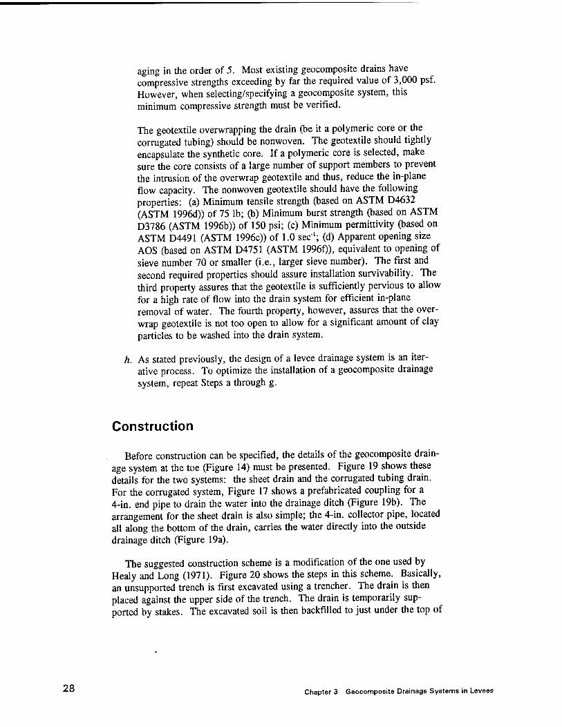
aging in the order of 5. Most existing geocomposite drains have compressive strengths exceeding by far the required value of 3,000 psf. However, when selecting/specifying a geocomposite system, this minimum compressive strength must be verified.
The geotextile overwrapping the drain (be it a polymeric core or the corrugated tubing) should be nonwoven. The geotextile should tightly encapsulate the synthetic core. If a polymeric core is selected, make sure the core consists of a large number of support members to prevent the intrusion of the overwrap geotextile and thus, reduce the in-plane flow capacity. The nonwoven geotextile should have the following properties: (a) Minimum tensile strength (based on ASTM D4632 (ASTM 1996d)) of 75 lb; (b) Minimum burst strength (based on ASTM D3786 (ASTM 1996b)) of 150 psi; (c) Minimum permittivity (based on ASTM D4491 (ASTM 1996c)) of 1.0 sec"1; (d) Apparent opening size AOS (based on ASTM D4751 (ASTM 1996f)), equivalent to opening of sieve number 70 or smaller (i.e., larger sieve number). The first and second required properties should assure installation survivability. The third property assures that the geotextile is sufficiently pervious to allow for a high rate of flow into the drain system for efficient in-plane removal of water. The fourth property, however, assures that the over- wrap geotextile is not too open to allow for a significant amount of clay particles to be washed into the drain system.
h. As stated previously, the design of a levee drainage system is an iter- ative process. To optimize the installation of a geocomposite drainage system, repeat Steps a through g.
Construction
Before construction can be specified, the details of the geocomposite drain- age system at the toe (Figure 14) must be presented. Figure 19 shows these details for the two systems: the sheet drain and the corrugated tubing drain. For the corrugated system, Figure 17 shows a prefabricated coupling for a 4-in. end pipe to drain the water into the drainage ditch (Figure 19b). The arrangement for the sheet drain is also simple; the 4-in. collector pipe, located all along the bottom of the drain, carries the water directly into the outside drainage ditch (Figure 19a).
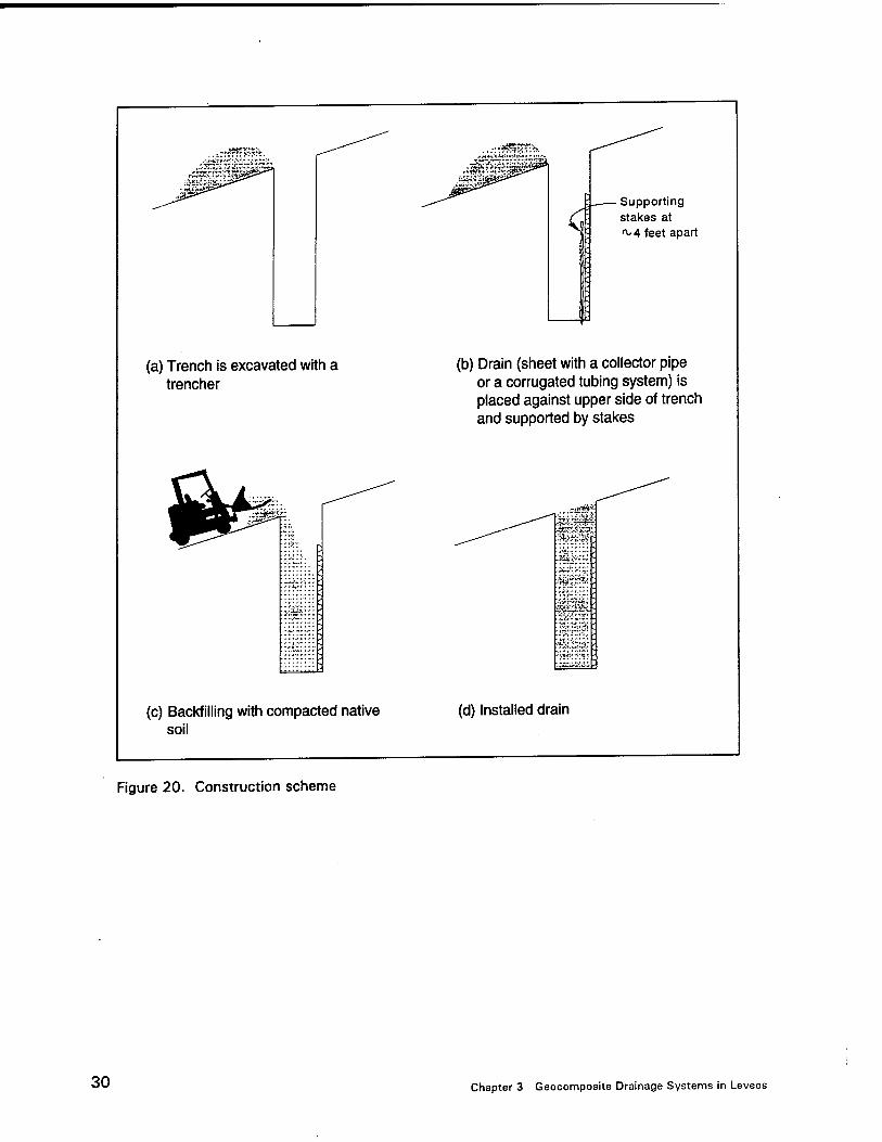
The suggested construction scheme is a modification of the one used by Healy and Long (1971). Figure 20 shows the steps in this scheme. Basically, an unsupported trench is first excavated using a trencher. The drain is then placed against the upper side of the trench. The drain is temporarily sup- ported by stakes. The excavated soil is then backfilled to just under the top of
28 Chapter 3 Geocomposite Drainage Systems in Levees

Sheet drain
Collector - pipe
(a) Sheet drainage system
Corrugated tubing drainage system
Backfilled with native soil
Drainage ditch
7AWAWAWAWAWA\H
Backfilled with native soil
End outlet (see Figure 17)
K Drainage ditch
v/xv kv>\VA^A^/A\VA\\1 - AN
■4" pipe
(b) Corrugated tubing drainage system
Figure 19. Detail showing transition from installed geocomposite drainage systems to a drainage ditch at toe
Chapter 3 Geocomposite Drainage Systems in Levees 29
.. **J&$F#J£#.'V:
(a) Trench is excavated with a trencher
■:?jp£
(c) Backfilling with compacted native soil
Figure 20. Construction scheme
-' V*'*5ä »3"T T^fc
• Supporting stakes at ^ 4 feet apart
(b) Drain (sheet with a collector pipe or a corrugated tubing system) is placed against upper side of trench and supported by stakes
Sj^Sl
(d) Installed drain
30 Chapter 3 Geocomposite Drainage Systems in Levees

the drain. It is desirable to compact the backfill as it is being replaced. However, with an extremely narrow and possibly deep trench, this may not always be possible.
Chapter 3 Geocomposite Drainage Systems in Levees 31

4 Conclusion
As the plasticity of the clay increases, numerous cracks tend to develop in levees. These cracks deepen during cycles of long dry spells and heavy rain- falls. These cycles also involve shrinkage and swell of the cracked clay zone resulting in a progressive reduction of the shear strength of the clay. Further- more, water filling cracks and fissures generates hydrostatic forces. The water is also being slowly absorbed by the cracked clay, progressively increasing its weight. These mechanisms result in an increase in slide driving forces simultaneously with a decrease in shear strength. It also results in deepening of the cracked clay zone which may eventually reach a depth of 9 ft. Following a heavy rainfall, the end result may be an occasional slough- ing failure. Fast removal of runoff water from the interconnected network of cracks should alleviate the surficial instability problem.
A general overview of geocomposite drainage systems has been presented in this report. The variety of such drains, some of their typical civil engineer- ing applications, their limitations, and typical required properties, has been illustrated. This illustrative presentation serves as a general and instructive introduction to geocomposite drainage systems.
An application to levees, to remedy the sloughing instability via rapid drainage, is introduced. The geocomposite drainage system is used to drain surface water that percolates into the cracked zone. Two drainage systems are addressed, a thin system and a thick system. Detailed design steps, ranging from estimation of required flow capacity of the drainage system, to selecting the system's layout, to choosing the actual system utilizing ASTM test meth- ods, to specifying safety factors, are described. Also suggested is an instal- lation procedure. The design and construction details are custom made to address and solve the problem of surficial stability of levees through fast removal of rainfall water.
The proposed utilization of geocomposite drainage system is based on experience with such systems and on sound engineering principles. The appli- cation of geocomposite drainage systems in levees, as detailed in this report, is new; i.e., it is an extrapolation of existing practices. Therefore, it is con- sidered a temporary measure to improve the surficial stability of levee slopes. A full-scale field test is strongly recommended to assess the effectiveness of
32 Chapter 4 Conclusion

using geocomposite drainage systems in levees. Such an experiment will likely lead to improvements in the design and construction techniques.
Chapter 4 Conclusion 33

References
Alvey, M. S. (1994). "Levee slide repair using a double application of hydrated lime." Proceedings ofREMR Workshop on Levee Rehabilitation. Compiled by E. B. Perry, U.S. Army Engineer Waterways Experiment Station, Vicksburg, MS, 75-76.
American Society for Testing and Materials. (1996). 1996 Annual Book of ASTM Standards. Philadelphia, PA.
a. D 1621, Standard test method for compressive properties of rigid cellular plastics.
b. D 3786, Standard test method for hydraulic bursting strength of knitted goods and nonwoven fabrics - diaphragm bursting strength tester method.
c. D 4491, Test methods for water permeability of geotextiles by permittivity.
d. D 4632, Test method for breaking load and elongation of geotextiles (grab methods).
e. D 4716, Test method for constant head hydraulic transmission (in-plane flow) of geotextiles and geotextile related products.
f. D 4751, Test method for determining apparent opening size of geotextile.
Fleming, R. L., Sills, G. L., and Stewart, E. S. (1994). "Lime stabilization of levee slopes." Proceedings ofREMR Workshop on Levee Rehabilitation. Compiled by E. B. Perry, U.S. Army Engineer Waterways Experiment Station, Vicksburg, MS, 79-87.
Healy, K. A., and Long, R. P. (1971). "Prefabricated subsurface drains," Highway Research Record (360), 57-64.
34 References

Hershfield, D. M. (1961). "Rainfall frequency atlas of the United States," Technical Paper No. 40, U.S. Government Printing Office, Washington, DC.
Hunt, T. R. (1993). "Curtain drains," Report No. CDOT-DTD-R-93-12, Colorado Department of Transportation, Division of Transportation Development, Denver, CO.
Kraemer, S. R., and Smith, A. D. (1986). "Geocomposite drains, Vol. I: Engineering assessment and preliminary guidelines," Report No. FHWA/RD-86/171, Contract No. DTFH61-83-C-00101, Haley and Aldrich, Inc., Cambridge, MA., submitted to Office of Research and Development, Federal Highway Administration, McLean, VA.
Koerner, R. M. (1994). Designing with geosynthetics, 3rd ed., Prentice Hall, Englewood Cliffs, NJ.
Massoth, D., and Ehlman, B. (1994). "Lime stabilization slide repair at Bardwell Lake embankment." Proceedings ofREMR Workshop on Levee Rehabilitation. Compiled by E. B. Perry, U.S. Army Engineer Waterways Experiment Station, Vicksburg, MS, 63-73.
Murray, R. T., and McGown, A. (1992). "Ground engineering applications of fin drains for highways," Transport and Road Research Laboratory (TRRL), Application Guide 20, ISSN 0266-5255, Crowthorne, Berkshire, RG11 6AU, UK.
Seelye, E. E. (1960). Data book for civil engineers. Volume 1 - Design, 3rd ed., Wiley, New York.
Sills, G. L., and Fleming, R. L. (1994). "Slope stabilization with stone-fill trenches." Proceedings ofREMR Workshop on Levee Rehabilitation. Compiled by E. B. Perry, U.S. Army Engineer Waterways Experiment Station, Vicksburg, MS, 88-99.
References 35


REPORT DOCUMENTATION PAGE Form Approved OMB No. 0704-0188
Public reporting burden for this collection of information is estimated to average 1 hour per response, including the time for reviewing instructions, searching existing data sources, gathenng and maintaining the data needed and completing and reviewing the collection of information. Send comments regarding this burden estimate or any other aspect of this collection of information, including suggestions for reducing tWs'burden, to Washington Headquarters Services, Directorate for Information Operations and Reports, 1215 Jefferson Davis Highway, Suite 1204, Arlington, VA22202-4302, and to the Office of Management and Budget Paperwork Reduction Project (0704-0188), Washington, DC20503. ___
1.AGENCY USE ONLY (Leave blank) 2.REPORT DATE
October 1996
3.REPORT TYPE AND DATES COVERED
Final report
4.TITLE AND SUBTITLE
Use of Geocomposite Drainage Systems as a Temporary Measure to Improve the Surficial Stability of Levees
5.FUNDING NUMBERS
Contract No. DACW39-94-C-0073 Work Unit 32646
6.AUTHOR(S)
Dov Leshchinsky
7.PERFORMING ORGANIZATION NAME(S) AND ADDRESS(ES)
Leshchinsky, Inc.
33 The Horseshoe
Newark, DE 19711
9.SPONSORING/MONITORING AGENCY NAME(S) AND ADDRESS(ES) U.S. Army Corps of Engineers Washington, DC 20314-1000; U.S. Army Engineer Waterways Experiment Station 3909 Halls Ferry Road, Vicksburg, MS 39180-6199
8.PERFORMING ORGANIZATION REPORT NUMBER
10.SPONSORING/MONITORING AGENCY REPORT NUMBER
Technical Report REMR-GT-24
11.SUPPLEMENTARY NOTES Available from the National Technical Information Service, 5285 Port Royal Road, Springfield, VA 22161.
12a.DISTRIBUTION/AVAILABIUTY STATEMENT
Approved for public release; distribution is unlimited.
12b.DISTRIBUTION CODE
13.ABSTRACT (Maximum 200 words)
This report presents a method for the use of geocomposite drainage systems as a temporary measure to improve the surficial stability of levee slopes. The mechanisms leading to sloughing failure in cohesive soils are discussed. A general overview of the use of geocomposite drainage systems in geotechnical engineering is given. Detailed design steps, ranging from estimation of required flow capacity of the drainage system to selecting the system's layout, and specifying safety factors, are described. An installation procedure and construction details are discussed. The application of geocomposite drainage systems in levees, as detailed in this report, is new; i.e., it is an extrapolation of existing practices. Therefore, it is considered a temporary measure to improve the surficial stability of levee slopes. A full-scale field test is recommended to assess the effectiveness of using geocomposite drainage systems in levees. Such an experiment will likely lead to improvements in design and construction techniques.
14.SUBJECT TERMS
Curtain drain Drainage systems Edge drain Geocomposite drains
Levees Seepage Slope stability Tension cracks
INSECURITY CLASSIFICATION OF REPORT
UNCLASSIFIED
INSECURITY CLASSIFICATION OF THIS PAGE
UNCLASSIFIED
INSECURITY CLASSIFICATION OF ABSTRACT
15.NUMBER OF PAGES 42
16.PRICECODE
20.LIMITATION OF ABSTRACT
NSN 7540-01-280-5500 Standard Form 298 (Rev. 2-89) Prescribed by ANSI Std. Z39-18 298-102