user manual - fuji spray |spray paint|high performance
TRANSCRIPT
CONTENTS
Contents . . . . . . . . . . . . . . . . . . . . . . . . . 1Safety Precautions . . . . . . . . . . . . . . 2 - 4Getting Started. . . . . . . . . . . . . . . . . . . . . 5Spray pattern . . . . . . . . . . . . . . . . . . . . . . 6Distance & Pressure Tube. . . . . . . . . . . . . 7Spraying techniques . . . . . . . . . . . . . . . . 8Aircap selection . . . . . . . . . . . . . . . . . . . 9Latex & Viscosity . . . . . . . . . . . . . . . 10 - 11Viscosity guide . . . . . . . . . . . . . . . . . . . .11Cleaning . . . . . . . . . . . . . . . . . . . . . . .11 - 12Finish Problems . . . . . . . . . . . . . . . . . . 13Spray Gun Problems . . . . . . . . . . . . . 14 -15Needle Packing & Seals. . . . . . . . . . . . 16Pressure Pot use . . . . . . . . . . . . . . . . . .17Turbine Care and Maintenance . . . . . . . .18Parts diagrams. . . . . . . . . . . . . . . . . . 19 - 21Spray Gun Holder . . . . . . . . . . . . . . . . . . 22Service information. . . . . . . . . . . . . . . . 23Warranty information . . . . . . . . . . . . . . 24CE Declaration . . . . . . . . . . . Back Cover
24
Fuji Industrial Spray Equipment Ltd. (“Fuji”) provides a 24 month limitedwarranty on the product to the original purchaser effective from the dateof purchase against defects in materials and workmanship.
The warranty does not cover damage or defects arising as a result ofabuse, misuse, accident, negligence, malfunction, corrosion, normalwear and tear, inadequate or lack of spray gun or other aspects ofmaintenance of the product, damage arising from improper assembly,installation or operation, or damage arising from the product beingused for a purpose other than that for which it was designed orintended. The warranty is void if repairs to the product are made orattempted by anyone other than Fuji or its authorized agent, or if anymodifications to the product are made or attempted.
Purchasers located in North America must obtain a Return MaterialAuthorization number by calling Fuji at 1-800-650-0930 beforereturning the product to Fuji or its designated representative.Purchasers located outside North America must contact the vendorfrom which they purchased the product. In all instances purchasersmust return the product together with proof of purchase and withshipping prepaid. For valid warranty claims the product will bereturned to the purchaser with shipping prepaid.
This is the only warranty provided by Fuji with respect to theproduct and is in lieu of any other warranties, express orimplied, including but not limited to any warranty ofmerchantability or fitness for a particular purpose. Fuji’s soleobligation under this warranty shall, at its option, be to eitherrepair or replace a product determined by Fuji to be defective.In no event shall Fuji be liable for loss or profits, incidental orconsequential damages, injury to any person or property, orany other damages of whatsoever nature.
Fuji Limited 2 Year Warranty

Please read these instructions carefully before using the equipment
GROUNDINGThis appliance must be grounded. If it should malfunction or break down,grounding provides a path of least resistance for electric current to reducethe risk of electric shock. This appliance is equipped with a cord havingan equipment-grounding conductor and grounding plug. The plug mustbe inserted into an appropriate outlet that is properly installed and groundedin accordance with all local codes and ordinances.
This appliance is for use on a nominal 120-volt circuit and has a groundingattachment plug that looks like the plug illustrated. Make sure that theappliance is connected to an outlet having the same configuration as theplug.
Please Note* For UK, Australia, Asia etc. your voltage will be220-240v. Check the label on the base of the turbine to ensureyour unit is at the correct voltage for your location.
ELECTRIC SHOCK HAZARDImproper connection of the equipment grounding conductor canresult in the risk of electric shock.· Check with a qualified electrician or service person if you are in doubt as to whether the outlet is properly grounded.· Use only a 3-wire extension cord that has a 3-blade grounding plug and a 3-slot receptacle that accepts the plug on the product.· An undersized cord results in a drop in line voltage and loss of power and overheating.· Do not modify the plug provided with the appliance. If it will not fit the outlet, have a proper outlet installed by a qualified electrician.· To reduce the risk of electric shock or injury, do not expose to rain.· Never allow unit to freeze.
2 23
For SERVICE & PARTS
USA
Cogent Bathtub Refinishing CoatingsPhone: 862-238-7224 Online: www.cogentcoatings.com
hvlp.netPhone: 800-650-0930 Online: www.hvlp.net
Phelps RefinishingPhone: 800-377-5662 Online: www.phelpsrefinishing.net
Paint Sprayers PlusPhone: 877-293-5826 Online: www.paintsprayersplus.com
CANADA
Fuji SprayPhone: 800-650-0930 Local: 416-650-1430
hvlp.caPhone: 800-650-0930 Online: www.hvlp.ca
UNITED KINGDOM
Axminster Power Tool Centre. Axminster, Devon, EnglandPhone: 01297 33656 Online: www.axminster.co.uk
AUSTRALIA & NZ
Spraychief Industries Campbellfield, Victoria 3061Phone: 03-9357-8788 Online: www.spraychief.com.au
PUERTO RICO
Eagle Tools Mfg. Corp San Lorenzo, Puerto Rico, 00754Phone: 787-736-0444
Fra-Marson Warehouse Distributors. San Juan PR, 00926Phone: 787-761-4810
RUSSIA
varnishop.ru St. Petersburg, RussiaPhone: 812-242-8040 Online: www.varnishop.ru
Copyright © 2014 Fuji Spray® Toronto. Canada
· Always store the unit inside in a dry location. Store on the fl oor if in a basement a basement setting.
· The operator must wear shoes and the fl oor must not be wet.
FIRE AND EXPLOSION HAZARDTurbine must not be used in an area contaminated by volatile or fl ammable materials since sparking can be expected in the nor-mal operation of the motor. This could ignite the contaminants causing a dangerous explosion. · Do not spray fl ammable or combustible materials near an open
fl ame or sources of ignition such as cigarettes, motors, and electrical equipment.
· Keep spray area well-ventilated. Keep a good supply of fresh air moving through the area. Keep turbine in a well ventilated area. · Do not spray turbine.· Turn off and disconnect power cord before servicing equipment.· Do not smoke in the spray area.· Do not operate light switches, engines, or similar spark producing products in the spray area.· Keep area clean and free of paint or solvent containers, rags, and other fl ammable materials.· Fire extinguisher equipment shall be present and working.· Sprayer generates sparks. When fl ammable liquid is used in or
near the sprayer or for fl ushing or cleaning, keep sprayer at least 20 feet (6 m) away from explosive vapors or spraying area.
· Ensure ground prongs are intact on sprayer and extension cords.· Always disconnect unit from main supply when fi lling the paint container. · Never use 1,1,1-trichloroethane, methylene chloride, other
halogenated hydrocarbon solvents or fl uids containing such solvents in equipment with aluminum wetted parts. Such use could result in a serious chemical reaction, with the possibility of explosion. Consult your fl uid suppliers to ensure that the fl uids being used are compatible with aluminum parts.
TOXIC FLUID OR FUMES HAZARDToxic fl uids or fumes can cause serious injury or death if splashed in the eyes or on skin, inhaled, or swallowed.· Read MSDS (Material Safety Data Sheet) to know the specifi c hazards of the fl uids you are using.
322
· Always wear appropriate gloves and eye protection· Always wear a respirator or mask. Read all instructions of the respirator or mask to ensure that it will provide the necessary protection against the inhalation of harmful vapors. Please also check with the local jurisdiction.
· Paint, solvents, insecticides and other materials may be harmful if inhaled.
· Store hazardous fl uid in approved containers, and dispose of it according to applicable guideline.
· Do not stop or defl ect fl uid leaks with your hand or body.
EQUIPMENT MISUSE HAZARDMisuse of equipment can cause serious injury or death. · Never aim the spray gun at another person or animal. In the event of injury, seek expert medical advice immediately. · Do not operate or spray near children. Keep children away from equipment at all times.· Do not overreach or stand on an unstable support. Keep eff ective footing and balance at all times.· Stay alert and watch what you are doing.· Do not operate the unit when fatigued or under the infl uence of drugs or alcohol.· Do not kink or over-bend the hose.· Do not use the hose as a strength member to pull or lift the equipment.· Do not cover turbine case as this will restrict air to the intake and result to overheating and premature failure of the motor. · Do not carry turbine while spraying.· Check the hose, hose connectors and power cord daily. Any worn or damaged parts should be replaced immediately. · Use only genuine Fuji Spray replacement parts. · It is normal for the turbine air outlet (manifold) to become hot during use, please allow your Fuji Spray turbine to cool for a few minutes before removing the hose from the turbine manifold.
4 21
Prop 65 Warning for California Residents WARNING: This product may contain chemicals known to the State of California to cause cancer, birth defects, or other reproductive harm.
520
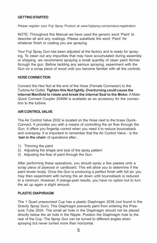
GETTING STARTED
Please register your Fuji Spray Product at www.fujispray.com/product-registration
NOTE: Throughout this Manual we have used the generic word ‘Paint’ todescribe all and any coatings. Please substitute the word ‘Paint’ forwhatever finish or coating you are spraying.
Your Fuji Spray Gun has been adjusted at the factory and is ready for spray-ing. To clean out any impurities that may have accumulated during assemblyor shipping, we recommend spraying a small quantity of clean paint thinnerthrough the gun. Before tackling any serious spraying, experiment with theGun on a scrap piece of wood until you become familiar with all the controls.
HOSE CONNECTION
Connect the Hex Nut at the end of the Hose (Female Connector) to theTurbine Air Outlet. Tighten this Nut lightly. Overturning could cause theinternal Manifold to rotate and break the internal Seal to the Motor. A MaleQuick Connect Coupler 2046M is available as an accessory for the connec-tion to the turbine.
AIR CONTROL VALVE
The Air Control Valve 2032 is located on the Hose next to the brass Quick-Connect. It provides you with a means of controlling the air flow through theGun. It offers you fingertip control when you need it to reduce bouncebackand overspray. It is important to remember that the Air Control Valve - is the‘last in the chain’ of operations after...
1) Thinning the paint2) Adjusting the shape and size of the spray pattern3) Adjusting the flow of paint through the Gun.
After performing these operations, you should spray a few passes onto ascrap piece of plywood or cardboard. This will allow you to determine if thepaint levels nicely. Once the Gun is producing a perfect finish with full air, youmay then experiment with turning the air down until bounceback is reducedto a mininum. However, if orange-peel results, you have no option but to turnthe air up again a slight amount.
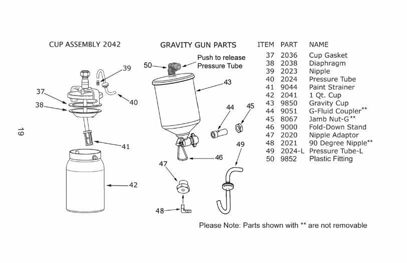
PLASTIC DIAPHRAGM
The 1 Quart pressurized Cup has a plastic Diaphragm 2038 (not found in theGravity Spray Gun). This Diaphragm prevents paint from entering the Pres-sure Tube 2024. The small air hole in the Diaphragm should not be placeddirectly below the air hole in the Nipple. Position the Diaphragm hole to therear of the Cup. The Spray Gun can be turned to different angles whenspraying but never turned more than horizontal.
FUJI XPC SPRAY GUN
6 19
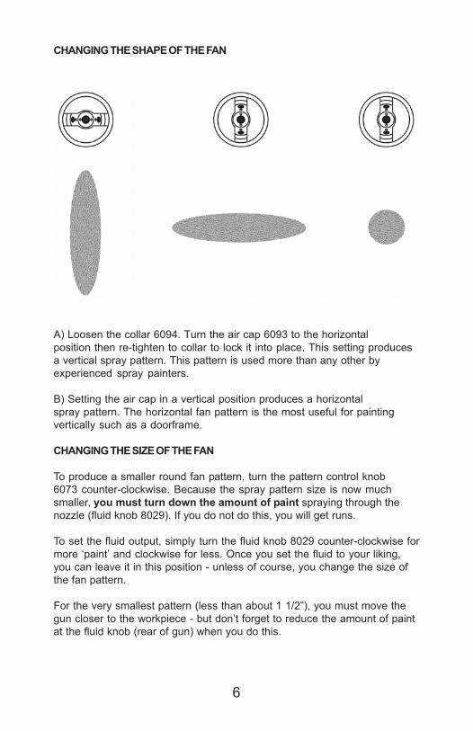
CHANGING THE SHAPE OF THE FAN
A) Loosen the collar 6094. Turn the air cap 6093 to the horizontalposition then re-tighten to collar to lock it into place. This setting producesa vertical spray pattern. This pattern is used more than any other byexperienced spray painters.
B) Setting the air cap in a vertical position produces a horizontalspray pattern. The horizontal fan pattern is the most useful for paintingvertically such as a doorframe.
CHANGING THE SIZE OF THE FAN
To produce a smaller round fan pattern, turn the pattern control knob6073 counter-clockwise. Because the spray pattern size is now muchsmaller, you must turn down the amount of paint spraying through thenozzle (fluid knob 8029). If you do not do this, you will get runs.
To set the fluid output, simply turn the fluid knob 8029 counter-clockwise formore ‘paint’ and clockwise for less. Once you set the fluid to your liking,you can leave it in this position - unless of course, you change the size ofthe fan pattern.
For the very smallest pattern (less than about 1 1/2”), you must move thegun closer to the workpiece - but don’t forget to reduce the amount of paintat the fluid knob (rear of gun) when you do this.
718
SPRAY GUN DISTANCE
The spray pattern is fan-shaped, so for a larger sized fan you do not have much choice - you will be at or close to the maximum 8” distance. It’s impos-sible to produce a large spray pattern if you hold the spraygun too close to the object - there is no room for the fan pattern to expand.
As you move closer with the gun, the fan will become a smaller size. So for instance, what was 10” wide at a distance of 8” becomes about 2” fan at 2” distance.
When you want to paint something that is, let’s say, 2” across and 6ft long - you will fi nd it much easier to follow the object if you move the gun closer. This will give you the ability to control your pass from side to side properly without wandering all over the place. Plus it will reduce overspray. Imagine spraying 1/2 chair spindles from 8” away with a spraygun when you don’t have bristles (as you do with a brush) to help guide you - it’s very diffi cult. So simply adjust the pattern to be smaller and cleaner (pattern control knob 6073) and move in close until the fan is the exact same size as the spindles. Once you are close, you will be able to guide the spraygun easily and it will not be as important to have a completely steady hand.
As an aside - it is usually not possible to bring the sprayhead close to the object with other methods of spraying (high-pressure for instance). Doing so would produce bounceback. The pressure is much less with turbine HVLP so this is not a problem.
THE PRESSURE TUBE
When spraying, never turn the gun upside down. The cup should never be higher than horizontal. The 1 Quart cup must always be lower than the gun. (On the gravity gun, it’s the opposite, the cup must be higher than the gun - at least no lower than horizontal). Upon stopping spraying for any reason, fi rst turn off the turbine. Disconnect the hose and then carefully open the cup to release pressure. It’s best to hang up the gun - use any type of hook or rod for this.
Do not stand the gun on a bench or even the fl oor because it will always be prone to falling over which could damage the spraygun and cause paint to fl ow up the pressure tube and into the spraygun.
Any paint in the pressure tube 2024 or nipples 2023 the tube is attached to, causes reduced amounts of paint through the gun. This is because the cup pressure is too low. Air is being restricted through the nipples by the paint blockage. The symptom will be little or no paint and the reason will always be the nipples or pressure tube being clogged with dried paint. We suggest always having extra pressure tubes on hand.
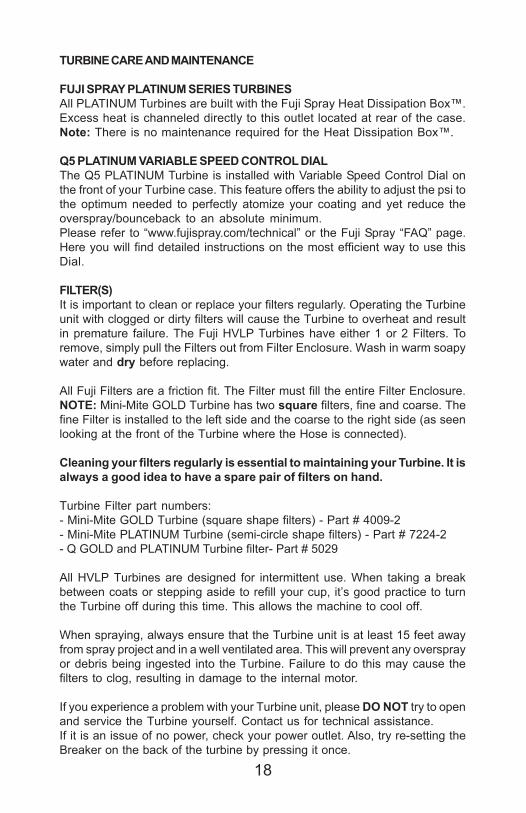
TURBINE CARE AND MAINTENANCE
FUJI SPRAY PLATINUM SERIES TURBINESAll PLATINUM Turbines are built with the Fuji Spray Heat Dissipation Box™. Excess heat is channeled directly to this outlet located at rear of the case. Note: There is no maintenance required for the Heat Dissipation Box™.
Q5 PLATINUM VARIABLE SPEED CONTROL DIALThe Q5 PLATINUM Turbine is installed with Variable Speed Control Dial on the front of your Turbine case. This feature off ers the ability to adjust the psi to the optimum needed to perfectly atomize your coating and yet reduce the overspray/bounceback to an absolute minimum.Please refer to “www.fujispray.com/technical” or the Fuji Spray “FAQ” page. Here you will fi nd detailed instructions on the most effi cient way to use this Dial.
FILTER(S) It is important to clean or replace your fi lters regularly. Operating the Turbine unit with clogged or dirty fi lters will cause the Turbine to overheat and result in premature failure. The Fuji HVLP Turbines have either 1 or 2 Filters. To remove, simply pull the Filters out from Filter Enclosure. Wash in warm soapy water and dry before replacing.
All Fuji Filters are a friction fi t. The Filter must fi ll the entire Filter Enclosure. NOTE: Mini-Mite GOLD Turbine has two square fi lters, fi ne and coarse. The fi ne Filter is installed to the left side and the coarse to the right side (as seen looking at the front of the Turbine where the Hose is connected).
Cleaning your fi lters regularly is essential to maintaining your Turbine. It is always a good idea to have a spare pair of fi lters on hand.
Turbine Filter part numbers:- Mini-Mite GOLD Turbine (square shape fi lters) - Part # 4009-2 - Mini-Mite PLATINUM Turbine (semi-circle shape fi lters) - Part # 7224-2- Q GOLD and PLATINUM Turbine fi lter- Part # 5029
All HVLP Turbines are designed for intermittent use. When taking a break between coats or stepping aside to refi ll your cup, it’s good practice to turn the Turbine off during this time. This allows the machine to cool off .
When spraying, always ensure that the Turbine unit is at least 15 feet away from spray project and in a well ventilated area. This will prevent any overspray or debris being ingested into the Turbine. Failure to do this may cause the fi lters to clog, resulting in damage to the internal motor.
If you experience a problem with your Turbine unit, please DO NOT try to open and service the Turbine yourself. Contact us for technical assistance.If it is an issue of no power, check your power outlet. Also, try re-setting the Breaker on the back of the turbine by pressing it once.
8 17
ACTUAL SPRAYING TECHNIQUES.
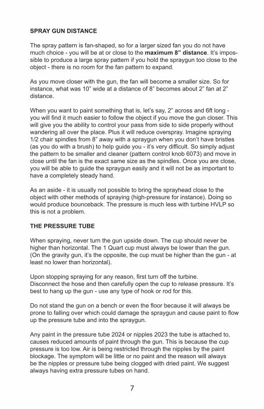
The spraygun should be held perpendicular to the surface at all times.HOLD THE GUN NO MORE THAN 8” (20cm) AWAY FROM THE SURFACETO BE PAINTED. But closer is ok.
CORRECT METHOD
Start moving the spraygun in the direction you want to spray and press thetrigger. Between each successive pass, overlap by about a quarter.
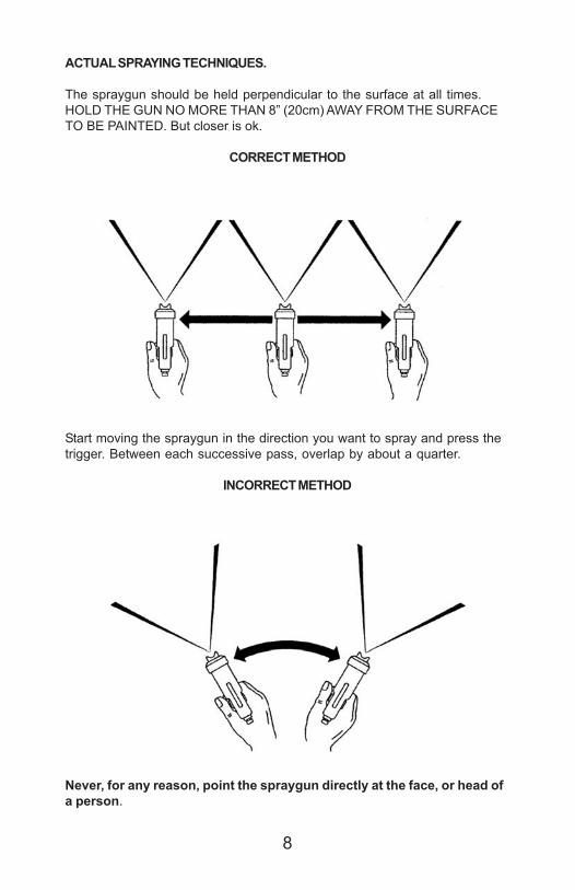
INCORRECT METHOD
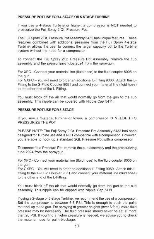
PRESSURE POT USE FOR 4-STAGE OR 5-STAGE TURBINE
If you use a 4-stage Turbine or higher, a compressor is NOT needed topressurize the Fuji Spray 2 Qt. Pressure Pot.
The Fuji Spray 2 Qt. Pressure Pot Assembly 5432 has unique features. Thesefeatures combined with additional pressure from the Fuji Spray 4-stageTurbine, allows the user to connect the larger capacity pot to the Turbinesystem without the need for a compressor.
To connect the Fuji Spray 2Qt. Pressure Pot Assembly, remove the cupassembly and the pressurizing tube 2024 from the spraygun.
For XPC - Connect your material line (fluid hose) to the fluid coupler 8005 onthe gun.For GXPC – You will need to order an additional L-Fitting 9060. Attach this L-Fitting to the G-Fluid Coupler 9051 and connect your material line (fluid hose)to the other end of the L-Fitting.
You must block off the air that would normally go from the gun to the cupassembly. This nipple can be covered with Nipple Cap 5411.
PRESSURE POT USE FOR 3-STAGE
If you use a 3-stage Turbine or lower, a compressor IS NEEDED TOPRESSURIZE THE POT.
PLEASE NOTE: The Fuji Spray 2 Qt. Pressure Pot Assembly 5432 has beendesigned for Turbine use and is NOT compatible with a compressor. However,you are able to hook up a standard 2Qt. Pressure Pot with a compressor.
To connect to a Pressure Pot, remove the cup assembly and the pressurizingtube 2024 from the spraygun.
For XPC - Connect your material line (fluid hose) to the fluid coupler 8005 onthe gun.For GXPC – You will need to order an additional L-Fitting 9060. Attach this L-fitting to the G-Fluid Coupler 9051 and connect your material line (fluid hose)to the other end of the L-Fitting.
You must block off the air that would normally go from the gun to the cupassembly. This nipple can be capped with Nipple Cap 5411.
If using a 2-stage or 3-stage Turbine, we recommend the use of a compressor.Set the compressor to between 6-8 PSI. This is enough to push the paintmaterial up to the gun. For spraying at greater heights (over 8 feet), more fluidpressure may be necessary. The fluid pressure should never be set at morethan 20 PSI. If you find a higher pressure is needed, we advise you to checkthe material hose for paint blockage.
Never, for any reason, point the spraygun directly at the face, or head ofa person.
916
AIRCAP SET SELECTION
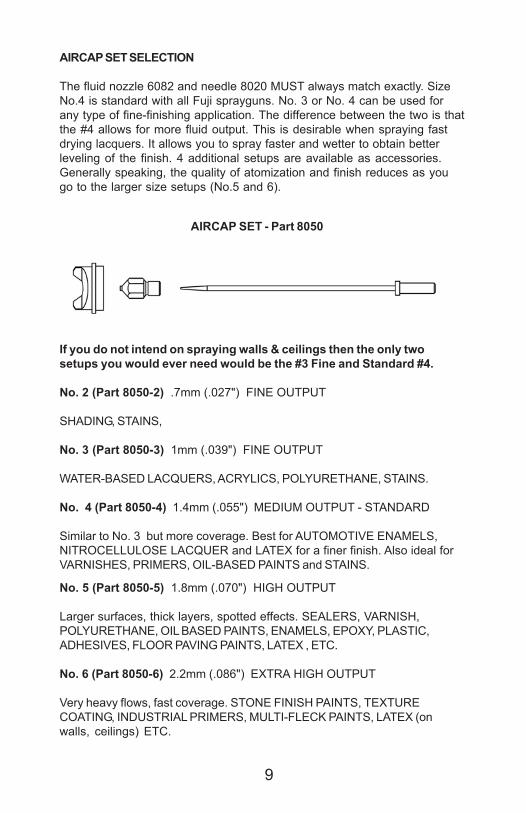
The fluid nozzle 6082 and needle 8020 MUST always match exactly. SizeNo.4 is standard with all Fuji sprayguns. No. 3 or No. 4 can be used forany type of fine-finishing application. The difference between the two is thatthe #4 allows for more fluid output. This is desirable when spraying fastdrying lacquers. It allows you to spray faster and wetter to obtain betterleveling of the finish. 4 additional setups are available as accessories.Generally speaking, the quality of atomization and finish reduces as yougo to the larger size setups (No.5 and 6).
If you do not intend on spraying walls & ceilings then the only twosetups you would ever need would be the #3 Fine and Standard #4.
No. 2 (Part 8050-2) .7mm (.027") FINE OUTPUT
SHADING, STAINS,
No. 3 (Part 8050-3) 1mm (.039") FINE OUTPUT
WATER-BASED LACQUERS, ACRYLICS, POLYURETHANE, STAINS.
No. 4 (Part 8050-4) 1.4mm (.055") MEDIUM OUTPUT - STANDARD
Similar to No. 3 but more coverage. Best for AUTOMOTIVE ENAMELS,NITROCELLULOSE LACQUER and LATEX for a finer finish. Also ideal forVARNISHES, PRIMERS, OIL-BASED PAINTS and STAINS.
No. 5 (Part 8050-5) 1.8mm (.070") HIGH OUTPUT
Larger surfaces, thick layers, spotted effects. SEALERS, VARNISH,POLYURETHANE, OIL BASED PAINTS, ENAMELS, EPOXY, PLASTIC,ADHESIVES, FLOOR PAVING PAINTS, LATEX , ETC.
No. 6 (Part 8050-6) 2.2mm (.086") EXTRA HIGH OUTPUT
Very heavy flows, fast coverage. STONE FINISH PAINTS, TEXTURECOATING, INDUSTRIAL PRIMERS, MULTI-FLECK PAINTS, LATEX (onwalls, ceilings) ETC.
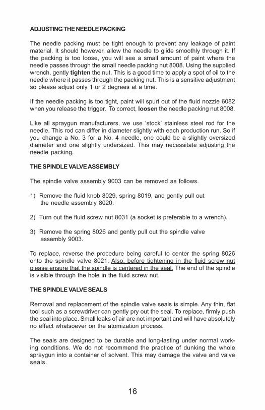
ADJUSTING THE NEEDLE PACKING
The needle packing must be tight enough to prevent any leakage of paintmaterial. It should however, allow the needle to glide smoothly through it. Ifthe packing is too loose, you will see a small amount of paint where theneedle passes through the small needle packing nut 8008. Using the suppliedwrench, gently tighten the nut. This is a good time to apply a spot of oil to theneedle where it passes through the packing nut. This is a sensitive adjustmentso please adjust only 1 or 2 degrees at a time.
If the needle packing is too tight, paint will spurt out of the fluid nozzle 6082when you release the trigger. To correct, loosen the needle packing nut 8008.
Like all spraygun manufacturers, we use ‘stock’ stainless steel rod for theneedle. This rod can differ in diameter slightly with each production run. So ifyou change a No. 3 for a No. 4 needle, one could be a slightly oversizeddiameter and one slightly undersized. This may necessitate adjusting theneedle packing.
THE SPINDLE VALVE ASSEMBLY
The spindle valve assembly 9003 can be removed as follows.
1) Remove the fluid knob 8029, spring 8019, and gently pull out the needle assembly 8020.
2) Turn out the fluid screw nut 8031 (a socket is preferable to a wrench).
3) Remove the spring 8026 and gently pull out the spindle valve assembly 9003.
To replace, reverse the procedure being careful to center the spring 8026onto the spindle valve 8021. Also, before tightening in the fluid screw nutplease ensure that the spindle is centered in the seal. The end of the spindleis visible through the hole in the fluid screw nut.
THE SPINDLE VALVE SEALS
Removal and replacement of the spindle valve seals is simple. Any thin, flattool such as a screwdriver can gently pry out the seal. To replace, firmly pushthe seal into place. Small leaks of air are not important and will have absolutelyno effect whatsoever on the atomization process.
The seals are designed to be durable and long-lasting under normal work-ing conditions. We do not recommend the practice of dunking the wholespraygun into a container of solvent. This may damage the valve and valveseals.
AIRCAP SET - Part 8050
1510
A WORD ABOUT LATEX
Although latex paint was never originally intended to be sprayed, aprofessional finish can be achieved by following a few simple rules.(Please do not confuse latex with the newer water-based coatings). Forwork such as cabinetry or trim, our equipment can be used successfullywith latex paint. The latex will have to be thinned with WATER - approxi-mately 20-30% depending on the brand of paint. And to improve thefinish even more, you can use an additive that will slow down the dryingprocess so that the paint levels out nicely. One product available isFLOETROL from the FLOOD Company in Ohio. In the USA Call 1-800-321-3444 for your nearest supplier. (In the U.K. 0845-0618899).
The ideal Aircap size setup is the #4 for household trim, louver doors etc.The Latex paint should be ‘finish-quality’ and not a cheaper grade.
When spraying Latex, please adjust the fluid knob to limit the paint to afiner spray. This will increase the ratio of air to paint and result in betteratomization and a beautiful finish. (Factually speaking, it doesn’tincrease the ratio of air to paint but does the opposite - it allows the airatomizing power to work on less paint thereby improving the quality ofatomization). Also, it is usually helpful to remove the air control valve sothat more air passes through the spraygun. Finally, adjust the pattern toa maximum size of 8” - 9” (20cm) - smaller is ok.
Although it is possible to use our equipment for house painting (walls),and many end users do, we feel that an airless gun or power roller isbetter suited for that kind of job. However, if you decide to do this kind ofwork, you will need the #6 Aircap set.
VISCOSITY
Follow the viscosity guide chart. You will eventually learn to thin thematerial by experience. Traditionally, lacquers were thinned 50/50 evenfor high pressure spraying but this much thinning is not necessary.However, coatings manufacturers are reformulating constantly so it isalways advisable to check with them. Thinning a product excessivelycauses more overspray as well as runs. Stringent air quality controls insome geographic locations may prohibit reducing by more than a certainpercentage. Please check with the local jurisdiction in this matter.
Remember, when you buy a can of paint, lacquer, polyurethane, varnishetc. over the counter, it will most likely be formulated for brushing. Thatmeans, it will be too viscous (thick) and will require thinning to spraysuccessfully. This is true even when spraying is mentioned on the labelof the can. Check with the manufacturer of the coating to obtain advice onthinning their product.
THE TRIGGER IS SLUGGISH
• The needle packing is too tight - see ADJUSTING THE NEEDLEPACKING. Page 14
• Bent needle• The valve seal 8025 is damaged - replace
POOR SPRAY PATTERN
• Damaged needle or nozzle• Nozzle is clogged• Air holes in air cap clogged• Aircap screwed in too tight• Gun too far from surface (max. 8” - 20cm)
PAINT AT THE AIR NOZZLE HOLES
• The fluid nozzle is loose and material is leaking around it -tighten with a adjustable wrench or 7/16” socket.
• Paint is entering the gun via the pressure tube (very rare) andbeing blown through the barrel to the aircap - see HOW TOPREVENT PAINT ENTERING THE PRESSURE TUBE. Page 4
GUN SPRAYS IN A PULSATING MANNER
• The needle packing has worn a little or is loose. Tighten• The cup is almost empty• The cup lid is not tight - air is escaping• The clear plastic pressure tube is leaking air. Replace• The pressure tube and/or nipple is clogged. Clear or replace• Gravity gun - turn the collar IN to alleviate back-pressure
EXCESSIVE OVERSPRAY
• The spray pattern size is too large for the item you are spraying• The gun is being held too far away - should be 8” max. (20cm)• Trigger on and off as you pass over the edges of the item• The product is too thin - try thinning less• Reduce the air by turning the air control valve to the point where
overspray is minimized but the finish still looks good• For ideal and comfortable spraying conditions, you should install
an extraction fan.* If you are spraying a flammable, combustibleproduct such as nitrocellulose lacquer, you must install anexplosion-proof fan (and explosion-proof lighting and switches)
* Please check with the local jurisdiction on this matter.

14 11
VISCOSITY GUIDE
To test the viscosity of the paint material, fill the viscosity cup to the brimand time how long it takes for the liquid to empty out through the hole. Werecommend you experiment to find the ideal viscosity for your applicationand record the information for the next time. The Fuji 3050 Viscosity Cup ismade to the exact same specs as the Ford #4 Cup (but not certified).
Always check with the manufacturer of the coating for assistance inthinning for spraying. If their product is only designed to be brushed, theymay not be too helpful. But remember that any type of coating can besprayed if it is thinned correctly and you have installed the ideal aircap set.
The chart below illustrates how many SECONDS it should take for thematerial to flow out of the viscosity cup. This is only an approximate guide.
Auto Cellulose 18 - 20 Primers 30 - 40Lacquers 18 - 20 Sanding Sealers 20 - 22Enamels 20 - 25 Stains UndilutedLatex 20 - 30 Creosote UndilutedOil-based 20 - 25 Polyurethanes 20 - 25
We suggest thinning around 25% to begin with but this may contravene theair quality control laws for your location. The solvent used for thinning isusually the solvent mentioned on the can (instructions for ‘cleaning thebrushes’). However, please check with the coatings manufacturer.
HVLP spraying is more friendly to the environment than most methods ofspraying. It reduces appreciably the amount of unnecessary misting andfogging (overspray) associated with high-pressure spraying. Spraying withNitrocellulose lacquer can be hazardous. The lacquer, fumes andoverspray are toxic, flammable and explosive. If spraying must be doneinside an enclosed area, ventilate well. Spray close to an open window ordoor and situate a fan to draw out the fumes (an explosion-proof motor andexplosion proof lighting will be necessary). PLEASE CHECK WITH THELOCAL AUTHORITY HAVING JURISDICTION ON THIS MATTER.
CLEANING
To clean the gun after each use, empty all paint from the cup. Use a solventsoaked rag to clean the residue in the cup. Then, spray some cleansolvent through the gun into a clean rag (to avoid filling the room withunnecessary spray) or a bucket. Repeat until the inside of the fluid pas-sages in the gun, metal fluid tube etc. are clean. Use the wet rag to wipe offthe aircap and tip of the fluid nozzle. The Aircap can be soaked in thinner.
Do not restrict the fluid nozzle when cleaning - this will drive thinned paintup the pressure tube and into the spraygun which is undersirable.
SPRAYGUN PROBLEMS
NO PAINT (OR VERY LITTLE PAINT)
THIS IS THE MOST COMMON PROBLEM ENCOUNTERED -
The air passing through the plastic tube 2024 to pressurize the cup isblocked. This means that either the tube itself, the check valve, or one ofthe two nipples 2023 is blocked. A pipe cleaner can be used for cleaningthe hole in the nipple. Please see more info on the pressure tube’ - Page 5
• Pressurizing tube and/or nipples are blocked - COMMON• The cup is not tightened down sufficiently by the quick-release
lever or the cup gasket 2036 is worn and leaking air• The cup is empty• The metal fluid tube is blocked with paint - rare• The fluid coupler is blocked with paint - rare
UNEVEN SPRAY PATTERN
One of the holes in the aircap may be blocked. Or, the paint could be dirtyand is partially blocking the fluid nozzle. Remove the aircap and clean bysoaking in solvent and using the soft bristle brush or a rag. NEVER usemetal objects to clean holes in the aircap.
LEAKAGE
If paint material comes out of the fluid nozzle without pulling the trigger...
• The needle is not seating in the fluid nozzle properly• The needle packing may be too tight preventing the needle from
moving• Foreign matter could be trapped between the needle and fluid
nozzle• The needle or fluid nozzle could be damaged or worn• Loose fluid nozzle• Wrong nozzle size installed
CUP LEAKS
• Oil above and below the lever to smooth the lever action• Change gasket/diaphragm - oil lever first to check• Leak around nipple - use Loctite to seal• Leak around side pins - use Loctite to seal• Leak through lid - remove nut under lid - use Loctite
12 13
If this type of cleaning is done while the paint is still wet in the gun, itshould be all that is necessary to keep the gun clean enough for next time.Do not leave liquids in the cup overnight or for long periods. The GravityGun can be cleaned without hooking up to the hose. Simply wind out thefluid knob all the way and pull the trigger - the thinner (solvent) willstream out of the fluid nozzle. Repeat until clean.
PLEASE DO NOT USE A WIRE BRUSH OR ANYTHING METAL TO CLEANTHE GUN OR CUP AS THIS WILL CAUSE DAMAGE.
DO NOT dissassemble the cup assembly - threads in your cup have beensealed at the factory to prevent leakage under pressure.
The standard 1 quart (1000cc) cup can be used with most coatings(including water-based). Also available as an accessory is our 2041Tteflon-coated cup.
CAUTION: Never soak the complete spraygun in solvent as this removesthe grease from the parts and distributes thinned paints throughout the airpassages. It could also damage internal parts such as the spindle valve8021 or valve seals 8025. It may however, be necessary sometimes tosoak the aircap 6093 and nozzle 6082. You may soak only the metal partsin solvent and clean with the soft bristle cleaning brush 9045. To reas-semble, first oil or grease all moving and threaded parts.
CAUTION: Do not store the gun with the cup clamped down hard as this willcause the gasket to flatten out. Do not lay the gun down on its side withliquid material in it.
CLEANING FLUID COMPONENTS
All Fuji fluid components in the spray gun are manufactured from stainlesssteel. To clean, flush solvent through the spraygun while the paint is stillwet inside the gun.
For a more thorough cleaning, remove all parts at the front of the barrel.(collar, aircap, fluid nozzle etc.) Also remove the needle (from the rear ofthe gun). Please note* the parts behind the nozzle are not removable. Thefluid coupler (where the cup assembly attaches) is not removable. Ifnecessary, use the supplied cleaning brush 9045 wetted with solvent toremove paint particles from inside the fluid coupler and from the areawhere the nozzle was installed. Please do not soak the whole gun insolvent, this should never be necessary and it could damage the valveassembly and valve seals.
The cup assembly can also be removed by loosening the swivel nut at thetop of the fluid tube. Upon re-installation, please do not overtighten theswivel nut - it is basically a hollow nut. If you apply extreme torque, you cancause damage to the nut.
FINISH PROBLEMS
ORANGE PEEL - If the finish is rough and resembles orange peel then thematerial is too thick. (Or perhaps you have the air control valve turned down- please check that it is fully open). The ‘paint’ will not atomize properly andthe surface will be spotty. To remedy this, add more thinner (or appropriatesolvent). For fast drying products such as lacquers, you may also want toadd a lacquer retarder. This will slow the drying time allowing the materialto flow out and level nicely.
Retarders are available for other coatings too, such as Penetrol for oil-based paints or Floetrol for latex house paints. These products go underdifferent names such as Flow-Out Additives etc. Please check with thecoatings manufacturer.
NOTE: With the newer water-based materials ‘orange peel’ is usually aresult of spraying on too thick a film. Try spraying an extremely THIN FILM,but still WET coat. With most other coatings, orange peel is caused bymaterial being too thick or not enough atomizing power. This is why wesuggest leaving the air control valve fully open when experimenting with anew coating material, otherwise it will cause confusion. If the the air controlvalve is fully open (or perhaps removed for Latex spraying) then orangepeel can only be one cause - the material is too thick and must be thinned.
GRITTY FINISH - If the material is too thin, it is likely to run or be over-atomized, producing a rough gritty finish. Try thinning the product less andspraying a wetter coat.
BLUSHING - Blushing is the common term used when the finish lookscloudy and white (sometimes also called blooming). It is caused bymoisture and is especially a problem when operating high pressure sprayequipment. The moisture comes from the compressor. This problem doesnot usually occur when using the Fuji turbine because the air from theturbine is warm, dry and uncontaminated. However, it is possible on veryhumid days to encounter slight blushing. Using a retarder will often allowmoisture to escape, preventing the milky look.
FISH EYES - If you are refinishing furniture or pianos, fish eyes couldbecome a problem. The cause is usually silicone or oil from polish whichhas been liquified by the paint stripper that has now soaked into the barewood. This silicone prevents the lacquer from adhering to the wood. Oneway to sometimes correct this is to seal in the silicone by misting on two orthree light coats of lacquer. Then spray on a regular wet coat. We do notrecommend the use of a product known as ‘Fish-Eye Drops’ which isessentially liquid silicone. Silicone will only contaminate the gun evenfurther. Anything that comes into contact with the silicone becomescontaminated - such as; rags, aprons, bench tops, gloves.
14 11
VISCOSITY GUIDE
To test the viscosity of the paint material, fill the viscosity cup to the brimand time how long it takes for the liquid to empty out through the hole. Werecommend you experiment to find the ideal viscosity for your applicationand record the information for the next time. The Fuji 3050 Viscosity Cup ismade to the exact same specs as the Ford #4 Cup (but not certified).
Always check with the manufacturer of the coating for assistance inthinning for spraying. If their product is only designed to be brushed, theymay not be too helpful. But remember that any type of coating can besprayed if it is thinned correctly and you have installed the ideal aircap set.
The chart below illustrates how many SECONDS it should take for thematerial to flow out of the viscosity cup. This is only an approximate guide.
Auto Cellulose 18 - 20 Primers 30 - 40Lacquers 18 - 20 Sanding Sealers 20 - 22Enamels 20 - 25 Stains UndilutedLatex 20 - 30 Creosote UndilutedOil-based 20 - 25 Polyurethanes 20 - 25
We suggest thinning around 25% to begin with but this may contravene theair quality control laws for your location. The solvent used for thinning isusually the solvent mentioned on the can (instructions for ‘cleaning thebrushes’). However, please check with the coatings manufacturer.
HVLP spraying is more friendly to the environment than most methods ofspraying. It reduces appreciably the amount of unnecessary misting andfogging (overspray) associated with high-pressure spraying. Spraying withNitrocellulose lacquer can be hazardous. The lacquer, fumes andoverspray are toxic, flammable and explosive. If spraying must be doneinside an enclosed area, ventilate well. Spray close to an open window ordoor and situate a fan to draw out the fumes (an explosion-proof motor andexplosion proof lighting will be necessary). PLEASE CHECK WITH THELOCAL AUTHORITY HAVING JURISDICTION ON THIS MATTER.
CLEANING
To clean the gun after each use, empty all paint from the cup. Use a solventsoaked rag to clean the residue in the cup. Then, spray some cleansolvent through the gun into a clean rag (to avoid filling the room withunnecessary spray) or a bucket. Repeat until the inside of the fluid pas-sages in the gun, metal fluid tube etc. are clean. Use the wet rag to wipe offthe aircap and tip of the fluid nozzle. The Aircap can be soaked in thinner.
Do not restrict the fluid nozzle when cleaning - this will drive thinned paintup the pressure tube and into the spraygun which is undersirable.
SPRAYGUN PROBLEMS
NO PAINT (OR VERY LITTLE PAINT)
THIS IS THE MOST COMMON PROBLEM ENCOUNTERED -
The air passing through the plastic tube 2024 to pressurize the cup isblocked. This means that either the tube itself, the check valve, or one ofthe two nipples 2023 is blocked. A pipe cleaner can be used for cleaningthe hole in the nipple. Please see more info on the pressure tube’ - Page 5
• Pressurizing tube and/or nipples are blocked - COMMON• The cup is not tightened down sufficiently by the quick-release
lever or the cup gasket 2036 is worn and leaking air• The cup is empty• The metal fluid tube is blocked with paint - rare• The fluid coupler is blocked with paint - rare
UNEVEN SPRAY PATTERN
One of the holes in the aircap may be blocked. Or, the paint could be dirtyand is partially blocking the fluid nozzle. Remove the aircap and clean bysoaking in solvent and using the soft bristle brush or a rag. NEVER usemetal objects to clean holes in the aircap.
LEAKAGE
If paint material comes out of the fluid nozzle without pulling the trigger...
• The needle is not seating in the fluid nozzle properly• The needle packing may be too tight preventing the needle from
moving• Foreign matter could be trapped between the needle and fluid
nozzle• The needle or fluid nozzle could be damaged or worn• Loose fluid nozzle• Wrong nozzle size installed
CUP LEAKS
• Oil above and below the lever to smooth the lever action• Change gasket/diaphragm - oil lever first to check• Leak around nipple - use Loctite to seal• Leak around side pins - use Loctite to seal• Leak through lid - remove nut under lid - use Loctite
1510
A WORD ABOUT LATEX
Although latex paint was never originally intended to be sprayed, aprofessional finish can be achieved by following a few simple rules.(Please do not confuse latex with the newer water-based coatings). Forwork such as cabinetry or trim, our equipment can be used successfullywith latex paint. The latex will have to be thinned with WATER - approxi-mately 20-30% depending on the brand of paint. And to improve thefinish even more, you can use an additive that will slow down the dryingprocess so that the paint levels out nicely. One product available isFLOETROL from the FLOOD Company in Ohio. In the USA Call 1-800-321-3444 for your nearest supplier. (In the U.K. 0845-0618899).
The ideal Aircap size setup is the #4 for household trim, louver doors etc.The Latex paint should be ‘finish-quality’ and not a cheaper grade.
When spraying Latex, please adjust the fluid knob to limit the paint to afiner spray. This will increase the ratio of air to paint and result in betteratomization and a beautiful finish. (Factually speaking, it doesn’tincrease the ratio of air to paint but does the opposite - it allows the airatomizing power to work on less paint thereby improving the quality ofatomization). Also, it is usually helpful to remove the air control valve sothat more air passes through the spraygun. Finally, adjust the pattern toa maximum size of 8” - 9” (20cm) - smaller is ok.
Although it is possible to use our equipment for house painting (walls),and many end users do, we feel that an airless gun or power roller isbetter suited for that kind of job. However, if you decide to do this kind ofwork, you will need the #6 Aircap set.
VISCOSITY
Follow the viscosity guide chart. You will eventually learn to thin thematerial by experience. Traditionally, lacquers were thinned 50/50 evenfor high pressure spraying but this much thinning is not necessary.However, coatings manufacturers are reformulating constantly so it isalways advisable to check with them. Thinning a product excessivelycauses more overspray as well as runs. Stringent air quality controls insome geographic locations may prohibit reducing by more than a certainpercentage. Please check with the local jurisdiction in this matter.
Remember, when you buy a can of paint, lacquer, polyurethane, varnishetc. over the counter, it will most likely be formulated for brushing. Thatmeans, it will be too viscous (thick) and will require thinning to spraysuccessfully. This is true even when spraying is mentioned on the labelof the can. Check with the manufacturer of the coating to obtain advice onthinning their product.
THE TRIGGER IS SLUGGISH
• The needle packing is too tight - see ADJUSTING THE NEEDLEPACKING. Page 14
• Bent needle• The valve seal 8025 is damaged - replace
POOR SPRAY PATTERN
• Damaged needle or nozzle• Nozzle is clogged• Air holes in air cap clogged• Aircap screwed in too tight• Gun too far from surface (max. 8” - 20cm)
PAINT AT THE AIR NOZZLE HOLES
• The fluid nozzle is loose and material is leaking around it -tighten with a adjustable wrench or 7/16” socket.
• Paint is entering the gun via the pressure tube (very rare) andbeing blown through the barrel to the aircap - see HOW TOPREVENT PAINT ENTERING THE PRESSURE TUBE. Page 4
GUN SPRAYS IN A PULSATING MANNER
• The needle packing has worn a little or is loose. Tighten• The cup is almost empty• The cup lid is not tight - air is escaping• The clear plastic pressure tube is leaking air. Replace• The pressure tube and/or nipple is clogged. Clear or replace• Gravity gun - turn the collar IN to alleviate back-pressure
EXCESSIVE OVERSPRAY
• The spray pattern size is too large for the item you are spraying• The gun is being held too far away - should be 8” max. (20cm)• Trigger on and off as you pass over the edges of the item• The product is too thin - try thinning less• Reduce the air by turning the air control valve to the point where
overspray is minimized but the finish still looks good• For ideal and comfortable spraying conditions, you should install
an extraction fan.* If you are spraying a flammable, combustibleproduct such as nitrocellulose lacquer, you must install anexplosion-proof fan (and explosion-proof lighting and switches)
* Please check with the local jurisdiction on this matter.
916
AIRCAP SET SELECTION
The fluid nozzle 6082 and needle 8020 MUST always match exactly. SizeNo.4 is standard with all Fuji sprayguns. No. 3 or No. 4 can be used forany type of fine-finishing application. The difference between the two is thatthe #4 allows for more fluid output. This is desirable when spraying fastdrying lacquers. It allows you to spray faster and wetter to obtain betterleveling of the finish. 4 additional setups are available as accessories.Generally speaking, the quality of atomization and finish reduces as yougo to the larger size setups (No.5 and 6).
If you do not intend on spraying walls & ceilings then the only twosetups you would ever need would be the #3 Fine and Standard #4.
No. 2 (Part 8050-2) .7mm (.027") FINE OUTPUT
SHADING, STAINS,
No. 3 (Part 8050-3) 1mm (.039") FINE OUTPUT
WATER-BASED LACQUERS, ACRYLICS, POLYURETHANE, STAINS.
No. 4 (Part 8050-4) 1.4mm (.055") MEDIUM OUTPUT - STANDARD
Similar to No. 3 but more coverage. Best for AUTOMOTIVE ENAMELS,NITROCELLULOSE LACQUER and LATEX for a finer finish. Also ideal forVARNISHES, PRIMERS, OIL-BASED PAINTS and STAINS.
No. 5 (Part 8050-5) 1.8mm (.070") HIGH OUTPUT
Larger surfaces, thick layers, spotted effects. SEALERS, VARNISH,POLYURETHANE, OIL BASED PAINTS, ENAMELS, EPOXY, PLASTIC,ADHESIVES, FLOOR PAVING PAINTS, LATEX , ETC.
No. 6 (Part 8050-6) 2.2mm (.086") EXTRA HIGH OUTPUT
Very heavy flows, fast coverage. STONE FINISH PAINTS, TEXTURECOATING, INDUSTRIAL PRIMERS, MULTI-FLECK PAINTS, LATEX (onwalls, ceilings) ETC.
ADJUSTING THE NEEDLE PACKING
The needle packing must be tight enough to prevent any leakage of paintmaterial. It should however, allow the needle to glide smoothly through it. Ifthe packing is too loose, you will see a small amount of paint where theneedle passes through the small needle packing nut 8008. Using the suppliedwrench, gently tighten the nut. This is a good time to apply a spot of oil to theneedle where it passes through the packing nut. This is a sensitive adjustmentso please adjust only 1 or 2 degrees at a time.
If the needle packing is too tight, paint will spurt out of the fluid nozzle 6082when you release the trigger. To correct, loosen the needle packing nut 8008.
Like all spraygun manufacturers, we use ‘stock’ stainless steel rod for theneedle. This rod can differ in diameter slightly with each production run. So ifyou change a No. 3 for a No. 4 needle, one could be a slightly oversizeddiameter and one slightly undersized. This may necessitate adjusting theneedle packing.
THE SPINDLE VALVE ASSEMBLY
The spindle valve assembly 9003 can be removed as follows.
1) Remove the fluid knob 8029, spring 8019, and gently pull out the needle assembly 8020.
2) Turn out the fluid screw nut 8031 (a socket is preferable to a wrench).
3) Remove the spring 8026 and gently pull out the spindle valve assembly 9003.
To replace, reverse the procedure being careful to center the spring 8026onto the spindle valve 8021. Also, before tightening in the fluid screw nutplease ensure that the spindle is centered in the seal. The end of the spindleis visible through the hole in the fluid screw nut.
THE SPINDLE VALVE SEALS
Removal and replacement of the spindle valve seals is simple. Any thin, flattool such as a screwdriver can gently pry out the seal. To replace, firmly pushthe seal into place. Small leaks of air are not important and will have absolutelyno effect whatsoever on the atomization process.
The seals are designed to be durable and long-lasting under normal work-ing conditions. We do not recommend the practice of dunking the wholespraygun into a container of solvent. This may damage the valve and valveseals.
AIRCAP SET - Part 8050
8 17
ACTUAL SPRAYING TECHNIQUES.
The spraygun should be held perpendicular to the surface at all times.HOLD THE GUN NO MORE THAN 8” (20cm) AWAY FROM THE SURFACETO BE PAINTED. But closer is ok.
CORRECT METHOD
Start moving the spraygun in the direction you want to spray and press thetrigger. Between each successive pass, overlap by about a quarter.
INCORRECT METHOD
PRESSURE POT USE FOR 4-STAGE OR 5-STAGE TURBINE
If you use a 4-stage Turbine or higher, a compressor is NOT needed topressurize the Fuji Spray 2 Qt. Pressure Pot.
The Fuji Spray 2 Qt. Pressure Pot Assembly 5432 has unique features. Thesefeatures combined with additional pressure from the Fuji Spray 4-stageTurbine, allows the user to connect the larger capacity pot to the Turbinesystem without the need for a compressor.
To connect the Fuji Spray 2Qt. Pressure Pot Assembly, remove the cupassembly and the pressurizing tube 2024 from the spraygun.
For XPC - Connect your material line (fluid hose) to the fluid coupler 8005 onthe gun.For GXPC – You will need to order an additional L-Fitting 9060. Attach this L-Fitting to the G-Fluid Coupler 9051 and connect your material line (fluid hose)to the other end of the L-Fitting.
You must block off the air that would normally go from the gun to the cupassembly. This nipple can be covered with Nipple Cap 5411.
PRESSURE POT USE FOR 3-STAGE
If you use a 3-stage Turbine or lower, a compressor IS NEEDED TOPRESSURIZE THE POT.
PLEASE NOTE: The Fuji Spray 2 Qt. Pressure Pot Assembly 5432 has beendesigned for Turbine use and is NOT compatible with a compressor. However,you are able to hook up a standard 2Qt. Pressure Pot with a compressor.
To connect to a Pressure Pot, remove the cup assembly and the pressurizingtube 2024 from the spraygun.
For XPC - Connect your material line (fluid hose) to the fluid coupler 8005 onthe gun.For GXPC – You will need to order an additional L-Fitting 9060. Attach this L-fitting to the G-Fluid Coupler 9051 and connect your material line (fluid hose)to the other end of the L-Fitting.
You must block off the air that would normally go from the gun to the cupassembly. This nipple can be capped with Nipple Cap 5411.
If using a 2-stage or 3-stage Turbine, we recommend the use of a compressor.Set the compressor to between 6-8 PSI. This is enough to push the paintmaterial up to the gun. For spraying at greater heights (over 8 feet), more fluidpressure may be necessary. The fluid pressure should never be set at morethan 20 PSI. If you find a higher pressure is needed, we advise you to checkthe material hose for paint blockage.
Never, for any reason, point the spraygun directly at the face, or head ofa person.
718
SPRAY GUN DISTANCE
The spray pattern is fan-shaped, so for a larger sized fan you do not havemuch choice - you will be at or close to the maximum 8" distance. It'simpossible to produce a large spray pattern if you hold the spraygun tooclose to the object - there is no room for the fan pattern to expand.
As you move closer with the gun, the fan will become a smaller size. So forinstance, what was 10" wide at a distance of 8" becomes about 2" fan at 2"distance.
When you want to paint something that is, let's say, 2" across and 6ft long -you will find it much easier to follow the object if you move the gun closer.This will give you the ability to control your pass from side to side properlywithout wandering all over the place. Plus it will reduce overspray. Imaginespraying 1/2 chair spindles from 8" away with a spraygun when you don'thave bristles (as you do with a brush) to help guide you - it's very difficult. Sosimply adjust the pattern to be smaller and cleaner (pattern control knob6073) and move in close until the fan is the exact same size as the spindles.Once you are close, you will be able to guide the spraygun easily and it willnot be as important to have a completely steady hand.
As an aside - it is usually not possible to bring the sprayhead close to theobject with other methods of spraying (high-pressure for instance). Doing sowould produce bounceback. The pressure is much less with turbine HVLPso this is not a problem.
THE PRESSURE TUBE
When spraying, never turn the gun upside down. The cup should never behigher than horizontal. The 1 Quart cup must always be lower than the gun.(On the gravity gun, it’s the opposite, the cup must be higher than the gun - atleast no lower than horizontal).
Upon stopping spraying for any reason, first turn off the turbine.Disconnect the hose and then carefully open the cup to release pressure.It’s best to hang up the gun - use any type of hook or rod for this.
Do not stand the gun on a bench or even the floor because it will always beprone to falling over which could damage the spraygun and cause paint toflow up the pressure tube and into the spraygun.
Any paint in the pressure tube 2024 or nipples 2023 the tube is attached to,causes reduced amounts of paint through the gun. This is because the cuppressure is too low. Air is being restricted through the nipples by the paint.blockage. The symptom will be little or no paint and the reason will alwaysbe the nipples or pressure tube being clogged with dried paint. We suggest
TURBINE CARE AND MAINTENANCE
FUJI SPRAY PLATINUM SERIES TURBINESAll PLATINUM Turbines are built with the Fuji Spray Heat Dissipation Box™.Excess heat is channeled directly to this outlet located at rear of the case.Note: There is no maintenance required for the Heat Dissipation Box™.
Q5 PLATINUM VARIABLE SPEED CONTROL DIALThe Q5 PLATINUM Turbine is installed with Variable Speed Control Dial onthe front of your Turbine case. This feature offers the ability to adjust the psi tothe optimum needed to perfectly atomize your coating and yet reduce theoverspray/bounceback to an absolute minimum.Please refer to “www.fujispray.com/technical” or the Fuji Spray “FAQ” page.Here you will find detailed instructions on the most efficient way to use thisDial.
FILTER(S)It is important to clean or replace your filters regularly. Operating the Turbineunit with clogged or dirty filters will cause the Turbine to overheat and resultin premature failure. The Fuji HVLP Turbines have either 1 or 2 Filters. Toremove, simply pull the Filters out from Filter Enclosure. Wash in warm soapywater and dry before replacing.
All Fuji Filters are a friction fit. The Filter must fill the entire Filter Enclosure.NOTE: Mini-Mite GOLD Turbine has two square filters, fine and coarse. Thefine Filter is installed to the left side and the coarse to the right side (as seenlooking at the front of the Turbine where the Hose is connected).
Cleaning your filters regularly is essential to maintaining your Turbine. It isalways a good idea to have a spare pair of filters on hand.
Turbine Filter part numbers:- Mini-Mite GOLD Turbine (square shape filters) - Part # 4009-2- Mini-Mite PLATINUM Turbine (semi-circle shape filters) - Part # 7224-2- Q GOLD and PLATINUM Turbine filter- Part # 5029
All HVLP Turbines are designed for intermittent use. When taking a breakbetween coats or stepping aside to refill your cup, it’s good practice to turnthe Turbine off during this time. This allows the machine to cool off.
When spraying, always ensure that the Turbine unit is at least 15 feet awayfrom spray project and in a well ventilated area. This will prevent any oversprayor debris being ingested into the Turbine. Failure to do this may cause thefilters to clog, resulting in damage to the internal motor.
If you experience a problem with your Turbine unit, please DO NOT try to openand service the Turbine yourself. Contact us for technical assistance.If it is an issue of no power, check your power outlet. Also, try re-setting theBreaker on the back of the turbine by pressing it once.
61
9
CH
AN
GIN
G T
HE
SH
AP
E O
F T
HE
FAN
A) Loosen the collar 6094. T
urn the air cap 6093 to the horizontalposition then re-tighten to collar to lock it into place. T
his setting producesa vertical spray pattern. T
his pattern is used more than any other by
experienced spray painters.
B) S
etting the air cap in a vertical position produces a horizontal
spray pattern. The horizontal fan pattern is the m
ost useful for paintingvertically such as a doorfram
e.
CH
AN
GIN
G T
HE
SIZ
E O
F T
HE
FAN
To produce a smaller round fan pattern, turn the pattern contro
l knob6073 counter-clockw
ise. Because the spray pattern size is now
much
smaller, yo
u m
ust tu
rn d
ow
n th
e amo
un
t of p
aint spraying through the
nozzle (fluid knob 8029). If you do not do this, you will get runs.
To set the fluid output, simply turn the fluid knob 8029 counter-clockw
ise form
ore ‘paint’ and clockwise for less. O
nce you set the fluid to your liking,you can leave it in this position - unless of course, you chang
e the size ofthe fan pattern.
For the very sm
allest pattern (less than about 1 1/2”), you must m
ove thegun closer to the w
orkpiece - but don’t forget to reduce the amount of paint
at the fluid knob (rear of gun) when you do this.
52
0
GE
TT
ING
STA
RT
ED
Ple
ase
reg
ister yo
ur F
uji S
pra
y Pro
du
ct at w
ww
.fujisp
ray.co
m/p
rod
uct-re
gistra
tion
NO
TE
: Throughout this M
anual we have used the generic w
ord ‘Paint’ to
describe all and any coatings. Please substitute the w
ord ‘Paint’ for
whatever finish or coating you are spraying.
Your F
uji Spray G
un has been adjusted at the factory and is ready for spray-
ing. To clean out any impurities that m
ay have accumulated during assem
blyor shipping, w
e recomm
end spraying a small quantity of clean paint thinner
through the gun. Before tackling any serious spraying, experim
ent with the
Gun on a scrap piece of w
ood until you become fam
iliar with all the controls.
HO
SE
CO
NN
EC
TIO
N
Connect the H
ex Nut at the end of the H
ose (Fem
ale Connector) to the
Turbine A
ir Outlet. T
igh
ten th
is Nu
t ligh
tly. Overtu
rnin
g co
uld
cause th
ein
ternal M
anifo
ld to
rotate an
d b
reak the in
ternal S
eal to th
e Mo
tor. A
Male
Quick C
onnect Coupler 2046M
is available as an accessory for the connec-
tion to the turbine.
AIR
CO
NT
RO
L VA
LVE
The A
ir Control V
alve 2032 is located on the Hose next to the b
rass Quick-
Connect. It provides you w
ith a means of controlling the air flow
through theG
un. It offers you fingertip control when you need it to reduce bounceback
and overspray. It is important to rem
ember that the A
ir Control V
alve - is the‘last in
the ch
ain’ of operations after...
1) Thinning the paint
2) Adjusting the shape and size of the spray pattern
3) Adjusting the flow
of paint through the Gun.
After perform
ing these operations, you should spray a few passe
s onto ascrap piece of plyw
ood or cardboard. This w
ill allow you to determ
ine if thepaint levels nicely. O
nce the Gun is producing a perfect finish
with full air, you
may then experim
ent with turning the air dow
n until bounceback is reducedto a m
ininum. H
owever, if orange-peel results, you have no option but to turn
the air up again a slight amount.
PL
AS
TIC
DIA
PH
RA
GM
The 1 Q
uart pressurized Cup has a plastic D
iaphragm 2038 (not found in the
Gravity S
pray Gun). T
his Diaphragm
prevents paint from entering the P
res-sure T
ube 2024. The sm
all air hole in the Diaphragm
should not be placeddirectly below
the air hole in the Nipple. P
osition the Diaphragm
hole to therear of the C
up. The S
pray Gun can be turned to different angles w
henspraying but never turned m
ore than horizontal.
FU
JI XP
C S
PR
AY
GU
N
· Paint, solvents, insecticides and other m
aterials may be harm
ful if inhaled.· S
tore hazardous fluid in approved containers, and dispose of it according to applicable guideline.· D
o not stop or deflect fluid leaks with your hand or body.
EQ
UIP
ME
NT
MIS
US
E H
AZ
AR
DM
isuse o
f equ
ipm
ent can
cause serio
us in
jury o
r death
.· N
ever aim the spray gun at another person or anim
al. In the event of injury, seek expert m
edical advice imm
ediately.· D
o not operate or spray near children. Keep children aw
ay from
equipment at all tim
es.· D
o not overreach or stand on an unstable support. Keep effective
footing and balance at all times.
· Stay alert and w
atch what you are doing.
· Do not operate the unit w
hen fatigued or under the influence of drugs or alcohol.· D
o not kink or over-bend the hose.· D
o not use the hose as a strength mem
ber to pull or lift the equipm
ent.· D
o not cover turbine case as this will restrict air to the intake and
result to overheating and premature failure of the m
otor.· D
o not carry turbine while spraying.
· Check the hose, hose connectors and pow
er cord daily. Any w
orn or dam
aged parts should be replaced imm
ediately.· U
se only genuine Fuji S
pray replacement parts.
· It is normal for the turbine air outlet (m
anifold) to become hot during
use, please allow your F
uji Spray turbine to cool for a few
minutes
before removing the hose from
the turbine manifold.
42
1
· Always store the unit inside in a dry location. Store on the floor if in a basement setting.· The operator must wear shoes and the floor must not be wet.
FIRE AND EXPLOSION HAZARDTurbine must not be used in an area contaminated by volatile orflammable materials since sparking can be expected in thenormal operation of the motor. This could ignite the contami-nants causing a dangerous explosion.· Do not spray flammable or combustible materials near an open flame or sources of ignition such as cigarettes, motors, and electrical equipment.· Keep spray area well-ventilated. Keep a good supply of fresh air moving through the area. Keep turbine in a well ventilated area.· Do not spray turbine.· Turn off and disconnect power cord before servicing equipment.· Do not smoke in the spray area.· Do not operate light switches, engines, or similar spark producing products in the spray area.· Keep area clean and free of paint or solvent containers, rags, and other flammable materials.· Fire extinguisher equipment shall be present and working.· Sprayer generates sparks. When flammable liquid is used in or near the sprayer or for flushing or cleaning, keep sprayer at least 20 feet (6 m) away from explosive vapors or spraying area.· Ensure ground prongs are intact on sprayer and extension cords.· Always disconnect unit from main supply when filling the paint container.
TOXIC FLUID OR FUMES HAZARDToxic fluids or fumes can cause serious injury or death ifsplashed in the eyes or on skin, inhaled, or swallowed.· Read MSDS (Material Safety Data Sheet) to know the specific hazards of the fluids you are using.· Always wear appropriate gloves and eye protection· Always wear a respirator or mask. Read all instructions of the respirator or mask to ensure that it will provide the necessary protection against the inhalation of harmful vapors. Please also check with the local jurisdiction.
322
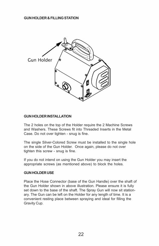
GUN HOLDER INSTALLATION
The 2 holes on the top of the Holder require the 2 Machine Screwsand Washers. These Screws fit into Threaded Inserts in the MetalCase. Do not over tighten - snug is fine.
The single Silver-Colored Screw must be installed to the single holeon the side of the Gun Holder. Once again, please do not overtighten this screw - snug is fine.
If you do not intend on using the Gun Holder you may insert theappropriate screws (as mentioned above) to block the holes.
GUN HOLDER USE
Place the Hose Connector (base of the Gun Handle) over the shaft ofthe Gun Holder shown in above illustration. Please ensure it is fullyset down to the base of the shaft. The Spray Gun will now sit station-ary. The Gun can be left on the Holder for any length of time. It is aconvenient resting place between spraying and ideal for filling theGravity Cup.
GUN HOLDER & FILLING STATION
Please read these instructions carefully before using the equipment
GROUNDINGThis appliance must be grounded. If it should malfunction or break down,grounding provides a path of least resistance for electric current to reducethe risk of electric shock. This appliance is equipped with a cord havingan equipment-grounding conductor and grounding plug. The plug mustbe inserted into an appropriate outlet that is properly installed and groundedin accordance with all local codes and ordinances.
This appliance is for use on a nominal 120-volt circuit and has a groundingattachment plug that looks like the plug illustrated. Make sure that theappliance is connected to an outlet having the same configuration as theplug.
Please Note* For UK, Australia, Asia etc. your voltage will be220-240v. Check the label on the base of the turbine to ensureyour unit is at the correct voltage for your location.
ELECTRIC SHOCK HAZARDImproper connection of the equipment grounding conductor canresult in the risk of electric shock.· Check with a qualified electrician or service person if you are in doubt as to whether the outlet is properly grounded.· Use only a 3-wire extension cord that has a 3-blade grounding plug and a 3-slot receptacle that accepts the plug on the product.· An undersized cord results in a drop in line voltage and loss of power and overheating.· Do not modify the plug provided with the appliance. If it will not fit the outlet, have a proper outlet installed by a qualified electrician.· To reduce the risk of electric shock or injury, do not expose to rain.· Never allow unit to freeze.
2 23
For SERVICE & PARTS
USA
Cogent Bathtub Refinishing CoatingsPhone: 862-238-7224 Online: www.cogentcoatings.com
hvlp.netPhone: 800-650-0930 Online: www.hvlp.net
Phelps RefinishingPhone: 800-377-5662 Online: www.phelpsrefinishing.net
Paint Sprayers PlusPhone: 877-293-5826 Online: www.paintsprayersplus.com
CANADA
Fuji SprayPhone: 800-650-0930 Local: 416-650-1430
hvlp.caPhone: 800-650-0930 Online: www.hvlp.ca
UNITED KINGDOM
Axminster Power Tool Centre. Axminster, Devon, EnglandPhone: 01297 33656 Online: www.axminster.co.uk
AUSTRALIA & NZ
Spraychief Industries Campbellfield, Victoria 3061Phone: 03-9357-8788 Online: www.spraychief.com.au
PUERTO RICO
Eagle Tools Mfg. Corp San Lorenzo, Puerto Rico, 00754Phone: 787-736-0444
Fra-Marson Warehouse Distributors. San Juan PR, 00926Phone: 787-761-4810
RUSSIA
varnishop.ru St. Petersburg, RussiaPhone: 812-242-8040 Online: www.varnishop.ru
Copyright © 2014 Fuji Spray® Toronto. Canada
CONTENTS
Contents . . . . . . . . . . . . . . . . . . . . . . . . . 1Safety Precautions . . . . . . . . . . . . . . 2 - 4Getting Started. . . . . . . . . . . . . . . . . . . . . 5Spray pattern . . . . . . . . . . . . . . . . . . . . . . 6Distance & Pressure Tube. . . . . . . . . . . . . 7Spraying techniques . . . . . . . . . . . . . . . . 8Aircap selection . . . . . . . . . . . . . . . . . . . 9Latex & Viscosity . . . . . . . . . . . . . . . 10 - 11Viscosity guide . . . . . . . . . . . . . . . . . . . .11Cleaning . . . . . . . . . . . . . . . . . . . . . . .11 - 12Finish Problems . . . . . . . . . . . . . . . . . . 13Spray Gun Problems . . . . . . . . . . . . . 14 -15Needle Packing & Seals. . . . . . . . . . . . 16Pressure Pot use . . . . . . . . . . . . . . . . . .17Turbine Care and Maintenance . . . . . . . .18Parts diagrams. . . . . . . . . . . . . . . . . . 19 - 21Spray Gun Holder . . . . . . . . . . . . . . . . . . 22Service information. . . . . . . . . . . . . . . . 23Warranty information . . . . . . . . . . . . . . 24CE Declaration . . . . . . . . . . . Back Cover
24
Fuji Industrial Spray Equipment Ltd. (“Fuji”) provides a 24 month limitedwarranty on the product to the original purchaser effective from the dateof purchase against defects in materials and workmanship.
The warranty does not cover damage or defects arising as a result ofabuse, misuse, accident, negligence, malfunction, corrosion, normalwear and tear, inadequate or lack of spray gun or other aspects ofmaintenance of the product, damage arising from improper assembly,installation or operation, or damage arising from the product beingused for a purpose other than that for which it was designed orintended. The warranty is void if repairs to the product are made orattempted by anyone other than Fuji or its authorized agent, or if anymodifications to the product are made or attempted.
Purchasers located in North America must obtain a Return MaterialAuthorization number by calling Fuji at 1-800-650-0930 beforereturning the product to Fuji or its designated representative.Purchasers located outside North America must contact the vendorfrom which they purchased the product. In all instances purchasersmust return the product together with proof of purchase and withshipping prepaid. For valid warranty claims the product will bereturned to the purchaser with shipping prepaid.
This is the only warranty provided by Fuji with respect to theproduct and is in lieu of any other warranties, express orimplied, including but not limited to any warranty ofmerchantability or fitness for a particular purpose. Fuji’s soleobligation under this warranty shall, at its option, be to eitherrepair or replace a product determined by Fuji to be defective.In no event shall Fuji be liable for loss or profits, incidental orconsequential damages, injury to any person or property, orany other damages of whatsoever nature.
Fuji Limited 2 Year Warranty